US8721646B2 - Methods and apparatus for a staple - Google Patents
Methods and apparatus for a stapleDownload PDFInfo
- Publication number
- US8721646B2 US8721646B2US11/545,273US54527306AUS8721646B2US 8721646 B2US8721646 B2US 8721646B2US 54527306 AUS54527306 AUS 54527306AUS 8721646 B2US8721646 B2US 8721646B2
- Authority
- US
- United States
- Prior art keywords
- shape
- staple
- leg
- bone
- plane
- Prior art date
- Legal status (The legal status is an assumption and is not a legal conclusion. Google has not performed a legal analysis and makes no representation as to the accuracy of the status listed.)
- Active - Reinstated, expires
Links
Images


Classifications
- A—HUMAN NECESSITIES
- A61—MEDICAL OR VETERINARY SCIENCE; HYGIENE
- A61B—DIAGNOSIS; SURGERY; IDENTIFICATION
- A61B17/00—Surgical instruments, devices or methods
- A61B17/064—Surgical staples, i.e. penetrating the tissue
- A61B17/0642—Surgical staples, i.e. penetrating the tissue for bones, e.g. for osteosynthesis or connecting tendon to bone
- A—HUMAN NECESSITIES
- A61—MEDICAL OR VETERINARY SCIENCE; HYGIENE
- A61B—DIAGNOSIS; SURGERY; IDENTIFICATION
- A61B17/00—Surgical instruments, devices or methods
- A61B2017/00831—Material properties
- A61B2017/00867—Material properties shape memory effect
Definitions
- the present inventionrelates to shape memory materials, and, more particularly, but not by way of limitation, to methods and an apparatus for utilizing a shape memory staple as an aid in operations including osteologic synthesis.
- contoured staplessuch as the Richard's Krackow HTO, Krackow HTO Blage Staple, and Osteotomy Fixation Staple all from Smith & Nephew, Inc.; Semi-oblique and Offset Staple from Orthomed, S.A. and Tibial Osteotomy Staple, Memometal, Industries. These implants have been designed to contour to the bone surfaces where they are placed.
- nickel-titanium stapleshave been used for their shape changing properties. These staples can be designed to retract their U-shaped legs so as to bring bone segments together. Like their predecessors they have also been contoured to match the anatomy of bone as illustrated by the Tibial Osteotomy Staple of Memometal Industries. This specific design uses a step in height to contour to the tapering portion of the tibia near the knee. This bony contour steps down from the width of the knee to the width of the shaft and can be well accommodated by the step staple. Though this staple has legs that deflect inwards during heating its stepped back does not change shape due to the undesired consequence of this shape change causing lifting of the back of the staple from the surface of the bone.
- a shape memory staplethat provides restraint forces in multiple planes would be beneficial to surgeons, as well as persons requiring bone surgeries, because the shape changing back of the staple would not lift from bone such as in the high tibial osteotomy example but will compress the bone together while displacing them relative to one another.
- a staple constructed from shape memory materialcompresses two bone segments together while applying offsetting forces provides a surgeon a unique new tool in the treatment of the human skeleton.
- the staplechanges shape out of the plane of the bone surface, thereby causing the bone to be shifted versus the staple being lifted.
- a surgeonmay displace a joint so as to create a new alignment to straighten a deformity.
- a surgeonmay move a joint of the spine back into alignment following two vertebra slipping relative to one another.
- compression and simultaneous offset forcesare exerted so as to realign bones, correct a deformity, or realign slipped vertebra.
- the staple according to the inventionincludes a first shape and a second shape, and a bridge having a first member and a second member, wherein the second member moves relative to the first member, thereby delivering a vertical displacement and an offset force.
- the second membermoves downward and towards the first member to deliver a combination of offsetting and contraction forces across the bridge.
- the staplefurther includes legs disposed on the bridge, such that the legs secure the staple to first and second bones that require an offset. Upon the transformation from the second shape to the first shape, the staple forces the second bone to move downward with respect to the first bone, and restrains the bones in the offset position.
- the second membermoves upward to extend a bridge width, thereby delivering a distraction force across the bridge and any legs disposed on the bridge.
- the upward movementfurther creates an offset force that may be utilized to reposition bones to anatomically correct positions relative to each other. Accordingly, it is possible to distract a first bone from a second bone, and reposition bones that have been dislodged bones.
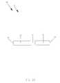
- FIG. 1Aprovides a frontal view of a staple according to a first embodiment.
- FIG. 1Bprovides a perspective view of the staple according to the first embodiment.
- FIG. 1Cprovides a top view of the staple according to the first embodiment.
- FIG. 1Dprovides frontal view illustrating some of the forces generated by the staple according to the first embodiment.
- FIG. 2Aprovides a frontal view of the staple in a second position according to the first embodiment.
- FIG. 2Bprovides a perspective view of the staple according to the first embodiment.
- FIG. 2Cprovides a top view of the staple in the second position according to the first embodiment.
- FIG. 2Dprovides a frontal view of the staple, and further showing angle associated with the second position of the first embodiment.
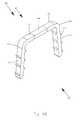
- FIG. 3provides a flowchart illustrating the method steps for utilizing the staple in an osteopathic procedure.
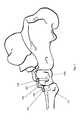
- FIG. 4provides a perspective view of an osteopathic procedure according to the first embodiment.
- FIG. 5provides a perspective view of a second example of an osteopathic procedure according to the first embodiment.
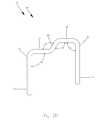
- FIG. 6Aprovides a frontal view of a staple in a first position according to a second embodiment.
- FIG. 6Bprovides a perspective view of the staple in the first position according to the second embodiment.
- FIG. 6Cprovides a top view of the staple in the first position according to the second embodiment.
- FIG. 6Dprovides a frontal view of the staple in the first position including forces generated by the staple according to the second embodiment.
- FIG. 7Aprovides a frontal view of a staple in a second position according to the second embodiment.
- FIG. 7Bprovides a perspective view of the staple in the second position according to the second embodiment.
- FIG. 7Cprovides a top view of the staple in the second position according to the second embodiment.
- FIG. 8Aprovides a section view of the staple secured to misaligned bones according to the second embodiment.
- FIG. 8Bprovides a section view of the bones and staple after spondylosis according to the second embodiment.
- FIG. 8Cprovides a flowchart illustrating the method steps for utilizing the staple in spondylosis according to the second embodiment.
- a staple 100may be constructed from virtually any alloy exhibiting a shape-memory effect.
- shape memory effect materialsinclude, but are not limited to nitinol, AuCd, FePt 3 , beta Brass, and InTI.
- Shape memory effect materialsallow an object to be: formed in an original shape; deformed while in a martensitic state; heated to a point where the deformed object phase changes from the martensitic state to an austenitic state, thereby returning the deformed object to its original shape; and cooled such that the object retains the original shape.
- the staple 100is formed in an original or first shape 127 ( FIGS. 1A-1C ), and annealed to set its original shape.
- the staple 100while cold and in its martensitic phase, is then deformed to a second shape 128 ( FIG. 2A-2C ).
- the staple 100is heated until it phase changes to an austenitic phase, thereby returning from the deformed or second shape 128 to the original or first shape 127 .
- the staple 100cools whereby the staple 100 retains the original first shape 127 .
- an end-use shapemay designate any shape between the second shape 128 and up to and including the first shape 127 .
- the amount of heat energy applied to the deformed shapedetermines the amount of transition from the second shape 128 to the first shape 127 .
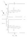
- the staple 100includes a first leg 110 , a second leg, 111 , and a bridge 101 , which, in the first shape 127 , has a bridge width 106 , and in the second shape 128 , has a bridge width 107 .
- the bridge 101has a first end 175 and a second end 176 and includes a first member 102 , a second member 103 , and a transition member 104 .
- the first member 102 and the second member 103are planar, however, one of ordinary skill in the art will recognize that the shape of the member 102 and 103 may be of any form, including, arcs, angles, and the like.
- first leg 110is connected to a first end 114 of the first member 102
- second end 115 of the first member 102is connected to a first end 117 of the transition member 104
- the second leg 111is connected to a first end 112 of the second member 103
- a second end 113 of the second member 103is connected to a second end 116 of the transition member 104 .
- the staple 100further includes a first bend 131 disposed between the first leg 110 and the first member 102 , a second bend 132 disposed between the first member 102 and the transition member 104 , a third bend 133 disposed between the transition member 104 and the second member 103 , and a fourth bend 134 disposed between the second member 103 and the second leg 111 .
- a horizontal axis 150 and a vertical axis 151have been provided.
- references to horizontal and vertical directionsare complementary to the cited axes 150 and 151 .
- a vertical planeis defined as a plane passing through the vertical axis 151 and the horizontal axis 150
- a horizontal planeis perpendicular to the vertical plane.
- the term “elevation”is utilized in reference to vertical displacement, wherein a lower elevation is recognized below the horizontal axis 150 and a higher elevation is recognized above the horizontal axis 150 . As such, an object may move from a given elevation to a higher or lower elevation.
- the staple 100further includes a first engagement surface 120 , a second engagement surface 121 , a third engagement surface 122 , a fourth engagement surface 123 , and a fifth engagement surface 124 .
- the engagement surfaces 120 through 123may extend along the complete length of the staple 100 dependent upon the cross-section of the staple 100 .
- the first engagement surface 120is disposed on an inner portion of the first leg 110
- the second engagement surface 121is disposed on an inner portion of the second leg 111
- the third engagement surface 122is disposed on an inner portion of the first member 102
- the fourth engagement surface 123is disposed beneath the second member 103
- the fifth engagement surface 124is disposed on an inner portion of the transition member 104 .
- the staple 100includes a rectangular cross-section; however, one of ordinary skill in the art will recognize that other cross-section shapes are possible, including square, round, oblong, or portions thereof.
- the first member 102is disposed substantially parallel to the horizontal axis 150 .
- the second member 103is disposed offset and substantially parallel to the first member 102 , and the first leg 110 and the second leg 111 are disposed substantially at equal angles to the respective connecting members 102 and 103 .
- the first leg 110is disposed at an angle 155 relative to the first member 102
- the second leg 111is disposed at an angle 156 relative to the second member 103 .
- the first and second legs 110 and 111are disposed approximately sixty degrees from the first and second members 102 and 103 .
- other anglesmay be utilized, dependent upon a desired retention force.
- the first and second legs 110 and 111extend in the same direction from the bridge 101 , such that the first leg 110 and the second leg 111 are angled toward each other, and have an internal clearance 125 .
- the transition member 104is disposed at an angle 157 relative to the first member 102 , and at an angle 158 relative to the second member 103 . In this example of the first shape 127 , the transition member 104 is disposed substantially perpendicular from the planes of the first member 102 and the second member 103 .
- first and second members 102 and 103the first and second legs 110 and 111 , and the transition member 104 , as described above are exemplary only, and that these relationships may be selected dependent upon a desired bone compression force or bone offset.
- first member 102 and the second member 103could lie in intersecting planes, the angles of the legs 110 and 111 may be different, and the transition member 104 does not have to be disposed perpendicular to the members.
- the lengths of the first and second members 102 and 103 , or the lengths of the transition member 104may be adjusted to deliver varying results, and, accordingly, all such adjustments should be construed as part of this disclosure.
- the staple 100is deformed as shown in FIGS. 2A-2D , such that the first member 102 and the second member 103 are offset and substantially parallel to each other, and the first leg 110 and the second leg 111 are substantially perpendicular to the first member 102 and the second member 103 .
- the first bend 131is extended to an angle 159
- the fourth bend 134is extended to an angle 160 .
- the angles 159 and 160span approximately ninety degrees.
- the second bend 132extends to angle 161
- the third bend 133extends to angle 162 , such that the transition member 104 is disposed at an angle relative to the first member 102 and the second member 103 , thereby increasing the clearance between the legs 110 and 111 to an internal clearance 126 .
- the transition member 104is disposed at an angle of approximately sixty degrees relative to the first and second members 102 and 103 .
- the staple 100Upon the application of heat energy from the temperature of the body or sources including but not limited to resistive, conductive or inductive heating, the staple 100 in a deformed or second shape 128 (deformed martensitic phase), commences to change from the martensitic state to the austenitic state. While application of heat energy is preferred, those of ordinary skill in the art will recognize that application in any form that results in shape change of the staple 100 may be used.
- the staple 100Upon completion of the austenitic phase change, the staple 100 has returned to the original or first shape 127 . Upon cooling, the staple 100 retains the original or first shape 127 .
- the phase change from the deformed or second shape 128 to the original or first shape 127creates forces as shown in FIG. 1D .
- the first bend 131moves in an arc from the angle 159 (approximately ninety degrees) to a second more acute angle 155 (approximately sixty degrees), thereby rotating the first leg 110 a prescribed distance toward the second leg 111 .
- the fourth bend 134moves from the angle 160 that is substantially perpendicular relative to the second member 103 to the angle 156 that is a more acute angle, thereby rotating the second leg 111 towards the first leg 110 a prescribed distance.
- the first leg 110rotates inward such that an end of the second leg 111 is potentially any position between its first and second shape 127 and 128 , but for this example, approximately two millimeters from its position in the second shape 128 .
- the second bend 132moves from the angle 161 (obtuse) to angle 157 (substantially perpendicular), and the third bend 133 moves from the angle 162 (obtuse angle position associated with the second shape 128 ) to the angle 158 (substantially perpendicular angle associated with the first shape 127 ). Accordingly, in the first shape 127 the transition member 104 is in a position that is substantially perpendicular relative to the first member 102 and the second member 103 .
- the rotation of the transition member 104 to the perpendicular position of the first shape 127pulls the second member 103 , the fourth bend 134 , and the second leg 111 toward the first leg 110 , such that the bridge width 106 of the first shape 127 is less than the bridge width 107 of the second shape 128 , thereby providing a translation component having increased compressive forces and an offset component.
- the end of the second leg 111experiences an increased displacement over the end of the first leg 110 .
- the translation component of this inventionis predominantly utilized to draw bone segments together for increased localized fusion, and to force one bone into an offset position relative to a second bone.
- compressive forcesare created between the first engagement surface 120 and the second engagement surface 121 , thereby restraining the staple 100 in an installed position.
- Compressive forcesare further created between the fifth engagement surface 124 and the first engagement surface 120 , thereby aiding in the translation and rotation of the second leg 111 and the transition member 104 .
- the rotation in the area of the second bend 132forces the transition member 104 and the second member 103 downward and toward the first leg 110 , thereby creating an offset force, whereby the second member 103 retains an attached bone at an elevation lower than the first member 102 .
- the resultant forces 170 applied by the first leg 110includes a horizontal component 172 that lies substantially parallel to the bridge 101 for clamping force, and a component 171 that lies substantially perpendicular to the bridge 101 , thereby providing an increased retention force.
- the bridge 101 having a bridge width 106contracts when moving from the second shape 128 to the first shape 127 , thereby providing additional compressive forces, and part of the translation component.
- the remaining portion of the translation componentis created by the return of the first and fourth bends 131 and 134 , to acute angles 155 and 156 as described in the first shape 127 .
- One of ordinary skill in the artwill recognize that regulating the amount of heat energy applied to the staple 100 is possible, thereby providing additional control of the amount of displacement, retention force, and the ability to utilize virtually any end use shape.
- FIG. 3provides a method flowchart illustrating steps for utilizing the staple 100 .
- a userfixates a first bone 145 and a second bone 146 at a desired working position.
- the processcontinues with step 20 , wherein a first location is identified in the first bone 145 and a second location is identified in the second bone at a spacing complementary to the internal clearance 126 between the first leg 110 and the second leg 111 when the staple is in the second shape 128 .
- Step 30provides for inserting the staple 100 into the first and second locations.
- the staple 100may be impacted into the first and second bones 145 and 146 , or alternatively, a first hole 148 of a size complementary to a cross-section of the first leg 110 is drilled into the first bone 145 , and a second hole 149 of a size complementary to the cross-section of the second leg 111 is drilled into the second bone 146 .
- the spacing between the first and second holes 148 and 149is complementary to the internal clearance 126 between the first leg 110 and the second leg 111 when the staple 100 is in the second shape 128 .
- the first leg 110is inserted into the first hole 148
- the second leg 111is inserted into the second hole 149 , thereby adapting to any offset created by anatomical conditions or creating offsets through the use of the staple 100 .
- step 40energy is applied to the staple 100 , thereby transforming the staple 100 from the second shape 128 to the first shape 127 , and compressing the first bone 145 and the second bone 146 together to promote fusion of the bones.
- the staple 100adapts to anatomical conditions that have offsets or conditions that have bones of different sizes.
- a staple 100may be utilized to create offsets.
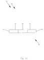
- an osteotomyis performed on a foot bone 152 requiring correction, thereby producing a calcaneal fragment 153 .
- the calcaneal fragment 153is shifted slightly on the foot bone 152 to a position that is more advantageous for use.
- the bones 152 and 153are then fixated in a position that allows a desired amount of offset complementary to the offset of the staple 100 , and a first hole 148 is drilled into the foot bone 152 , and a second hole 149 is drilled into the calcaneal fragment 153 at a spacing complementary to the spacing of the legs 110 and 111 , of the staple 100 in the second shape 128 .
- the staple 100is inserted into the first and second holes 148 and 149 , wherein the first member 102 is disposed adjacent to a largest bone.
- the staple 100transitions from the second shape 128 to the first shape 127 with the application of the forces previously described herein, thereby pulling the calcaneal fragment 153 toward the foot bone 152 , and permanently restraining the calcaneal fragment 153 in the desired offset position.
- the compression of the bones 152 and 153 towards each otherfurther promotes a bone fusion process.
- the calcaneal fragment 153reattaches to the foot bone 152 .
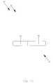
- the staple 100is utilized to provide an offset to a bone joint.
- a first foot bone 140 and a second foot bone 141require joining.
- the first member 102is utilized on the larger or first foot bone 140 .
- the processis nearly identical to the previous procedure, wherein the bones 140 and 141 are fixated in a corrective position that provides a desired amount of offset.
- the offsetis substantially identical to the offset between the first member 102 and the second member 104 of the staple 100 .
- a first hole 148is drilled into the first foot bone 140
- a second hole 149is drilled into the second foot bone 141 , at a spacing complementary to the spacing of the legs 110 and 111 of the staple 100 in the second shape 128 .
- the staple 100is then inserted into the drilled holes, such that the first member 102 is disposed adjacent to the first foot bone 140 .
- the staple 100transitions from the second shape 128 to the first shape 127 with the application of the forces previously described herein, thereby drawing the first foot bone 140 toward the second foot bone 141 , and permanently restraining the second foot bone 141 in the desired offset position.
- the compression between the first foot bone 140 and the second foot bone 141forces the bones to fuse together.
- transition member 104While this first embodiment has been shown with one transition member 104 and two bends disposed within the bridge 101 , and two legs, one of ordinary skill in the art will recognize that multiple transition members, bends, and legs may be utilized to provide increased rotation, increased offset from a first member 102 to a second member 103 , or increased force application by the engagement faces.
- a staple 200is constructed from virtually any alloy exhibiting shape-memory effects, and therefore includes an original or first shape 227 ( FIGS. 6A-6C ) and a deformed or second shape 228 ( FIGS. 7A-7C ), similar to that described in the first embodiment.
- the staple 200is usable at virtually any point along the transition between the second shape 228 and the first shape 227 .
- an end-use shapemay designate any shape between the second shape 228 and up to and including the first shape 227 .
- the amount of heat energy applied to the deformed shapedetermines the extent of transition from the second shape 228 to the first shape 227 .
- the staple 200includes a first leg 210 , a second leg, 211 , and a bridge 201 , which, in the first shape 227 , has a bridge width 206 , and in the second shape 228 , has a bridge width 207 .
- the bridge 201has a first end 275 and a second end 276 includes a first member 202 , a second member 203 , and a transition member 204 .
- the first member 202 and the second member 203are planar, however, one of ordinary skill in the art will recognize that the shape of members 202 and 203 may be of any form, including, arcs, angles, and the like.
- the first leg 210is connected to a first end 214 of the first member 202 , and a second end 215 of the first member 202 is connected to a first end 217 of the transition member 204 .
- the second leg 211is connected to a first end 212 of the second member 203 , and a second end 213 of the second member 203 is connected to a second end 216 of the transition member 204 .
- the staple 200further includes a first bend 231 disposed between the first leg 210 and the first member 202 , a second bend 232 disposed between the first member 202 and the transition member 204 , a third bend 233 disposed between the transition member 204 and the second member 203 , and a fourth bend 234 disposed between the second member 203 and the second leg 211 .
- the staple 200further includes a first engagement surface 220 , a second engagement surface 221 , a third engagement surface 222 , a fourth engagement surface 223 , a fifth engagement surface 224 , a sixth engagement surface 225 , and a seventh engagement surface 226 .
- the engagement surfaces 220 through 226may extend along the complete length of the staple 200 dependent upon the cross-section of the staple 200 .
- the first engagement surface 220is disposed on an inner portion of the first leg 210
- the second engagement surface 221is disposed on an inner portion of the second leg 211 .
- the third engagement surface 222is disposed on an inner portion of the first member 202
- the fourth engagement surface 223is disposed beneath the second member 203
- the fifth engagement surface 224is disposed on an inner portion of the transition member 204
- the sixth engagement surface 225is disposed on an outer portion of the first leg 210
- the seventh engagement surface 226is disposed on an outer portion of the second leg 211 .
- the staple 200includes a rectangular cross-section, however, one of ordinary skill in the art will recognize that other cross-section shapes are possible, including square, round, oblong, or portions thereof.
- the first engagement surface 220 , the second engagement surface 221 , the sixth engagement surface 225 , and the seventh engagement surface 226include barbs 219 for securing the staple 200 in position.
- the barbs 219are oriented such that the legs 210 and 211 may be inserted into holes, yet may not be pulled out of the holes without damaging the engaged structure.
- One of ordinary skill in the artwill recognize that the number and size of the barbs 219 may be adjusted to provide increased resistance forces or decreased resistance forces.
- a horizontal axis 250 and a vertical axis 251have been provided.
- references to horizontal and vertical directionsare complementary to the cited axes 250 and 251 .
- a vertical planeis defined as a plane passing through the vertical axis 251 and the horizontal axis 250
- a horizontal planeis perpendicular to the vertical plane.
- the term “elevation”is utilized in reference to vertical displacement, wherein a lower elevation is recognized below the horizontal axis 250 and a higher elevation is recognized above the horizontal axis 250 . As such, an object may move from a given elevation to a higher or lower elevation.
- the first member 202is disposed substantially parallel to the horizontal axis 250 .
- the second member 203 and the transition member 204are disposed substantially parallel and coplanar to the first member 202
- the first leg 210 and the second leg 211are disposed at substantially equal angles to the respective connecting members 202 and 203 .
- the first leg 210is disposed at an angle 255 relative to the first member 202
- the second leg 211is disposed at an angle 256 relative to the second member 203 .
- the first and second legs 210 and 211are disposed approximately one hundred and twenty degrees from the first and second members 202 and 203 , respectively.
- the first and second legs 210 and 211extend from the bridge 201 , such that the first leg 210 and the second leg 211 are angled away from each other, and have an internal clearance consistent with the bridge width 206 .
- the transition member 204is disposed at an angle 257 relative to the first member 202 , and at an angle 258 relative to the second member 203 . In this example of the first shape 227 , the transition member 204 is disposed substantially parallel and coplanar to the planes of the first member 202 and the second member 203 .
- first and second members 202 and 203the first and second legs 210 and 211 , and the transition member 204 , as described above are exemplary only, and that these relationships may be selected dependent upon a displacement or extension force.
- first member 202 and the second member 203could lie in intersecting planes, the angles of the legs 210 and 211 may be different, and the transition member 204 does not have to be disposed parallel to the members.
- the lengths of the first and second members 202 and 203 , or the lengths of the transition member 204may be adjusted to deliver varying results, and, accordingly, all such adjustments should be construed as part of this disclosure.
- the staple 200is deformed as shown in FIGS. 7A-7C , such that the first member 202 and the second member 203 are offset and substantially parallel to each other, and the first leg 210 and the second leg 211 are substantially perpendicular to the first member 202 and the second member 203 .
- the first bend 231is contracted to an angle 259
- the fourth bend 234is contracted to an angle 260 .
- the angles 259 and 260span approximately ninety degrees.
- the second bend 232contracts to angle 261
- the third bend 233contracts to angle 262 , such that the transition member 204 is disposed substantially perpendicular to the first member 202 and the second member 203 , thereby decreasing the clearance between the legs 210 and 211 to an internal clearance equivalent to the bridge width 207 .
- the transition member 204is disposed at an angle of approximately ninety degrees relative to the first and second members 202 and 203 .
- the staple 200has been shown with the legs 210 and 211 substantially perpendicular to the first and second members 202 and 203 , and the transition member 204 disposed at an angle of approximately ninety degrees relative to the first and second members 202 and 203 , one of ordinary skill in the art will recognize that other angles besides those shown may be utilized to deliver varying forces and lateral displacements. It should further be recognized that the use of parallel legs is conducive to insertion of a staple into pre-drilled holes; however, other angles may be utilized to address alternative situations, including the insertion of one leg at a time.
- the staple 200 in a deformed or second shape 228commences to change from the martensitic state to the austenitic state.
- the staple 200has returned to the original or first shape 227 .
- the staple 200retains the original or first shape 227 .
- a forceis created, and accordingly, the staple 200 may be utilized in applications where retaining and residual forces are required.
- the phase change from the deformed or second shape 228 to the original or first shape 227creates forces as shown in FIG. 6D .
- the first bend 231moves in an arc from the angle 259 (approximately ninety degrees) to a second more obtuse angle 255 (approximately one hundred degrees), thereby rotating the first leg 210 a prescribed distance away from the second leg 211 .
- the fourth bend 234moves from the angle 260 that is substantially perpendicular relative to the second member 203 to the angle 256 that is a more obtuse angle, thereby rotating the second leg 211 away from the first leg 210 a prescribed distance.
- the second bend 232moves from the angle 261 (substantially ninety degrees) to angle 257 (approximately one hundred and eighty degrees), and the third bend 233 moves from the angle 262 (perpendicular angle position associated with the second shape 228 ) to the angle 258 (approximately one hundred and eighty degrees associated with the first shape 227 ). Accordingly, in the first shape 227 the transition member 204 is in a position that is substantially parallel and coplanar relative to the first member 202 and the second member 203 .
- the rotation of the transition member 204 to the substantially parallel and coplanar position of the first shape 227pushes the fourth bend 234 , and the second leg 211 away from the first leg 210 , such that the bridge width 206 of the first shape 227 is greater than the bridge width 207 of the second shape 228 , thereby providing a translation component across the bridge 201 and increased extension forces at the legs 210 and 211 .
- extension forcesare created between the sixth and seventh engagement surfaces 225 and 226 , thereby providing distraction between connected bones so as to decompress nerves that may be trapped between bone segments.
- the rotation in the area of the second bend 232forces the transition member 204 and the second member 203 upward, thereby creating an offset force, whereby the second member 203 moves an attached bone at an elevation lower than the first member 202 to the plane even with the first member 202 .
- Extension forcesare further created in the horizontal direction by the first member 202 and the second member 203 as the transition member 204 and the second member 203 move into the same plane.
- the resultant forces 270 applied by the second leg 211 and the second member 203include a horizontal component 271 that lies substantially parallel to the bridge 201 for extending force, and a component 272 that lies substantially perpendicular to the bridge 201 , thereby providing an offsetting capability to realign bone segments that have slipped relative to one another.
- the bridge 201 having a bridge width 207extends when moving from the second shape 228 to the first shape 227 , thereby providing part of the translation component.
- the remaining portion of the translation componentis created by the extension of the first and fourth bends 231 and 234 , to obtuse angles 255 and 256 as described in the first shape 227 .
- One of ordinary skill in the artwill recognize that regulating the amount of energy applied to the staple 200 is possible, thereby providing additional control of the amount of displacement, retention force, and the ability to utilize virtually any end use shape along the transition from the second shape 228 to the first shape 227 .
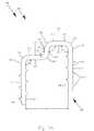
- the staple 200adapts to existing distracted bones such as those shown in FIG. 8A .
- the ability to adapt to distracted bones, particularly vertebrae in a spondylosis,allows forcible distraction and restraint of the bones 245 and 246 in the distracted position.
- the first bone 245 and the second bone 246are straightened such that contact between the bones 245 and 246 is not possible, thereby allowing a nerve cord to be decompressed.
- FIG. 200Further advantages of the staple 200 include the ability to move a first bone 245 and a second bone 246 into an anatomically correct position by applying heat energy to the staple 200 until the bone 246 attached to the second leg 211 is aligned with the bone 245 attached to the first leg 210 . Accordingly, virtually any amount of correction and restraint may be applied.
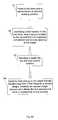
- FIG. 8Cprovides a method flowchart illustrating steps for utilizing the staple 200 .
- a userfixates a first bone 245 and a second bone 246 at a desired working position.
- the processcontinues with step 52 , wherein a first location is identified in the first bone 245 and a second location is identified in the second bone 246 at a spacing complementary to the internal clearance between the first leg 210 and the second leg 211 when the staple is in the second shape 228 .
- Step 53provides for inserting the staple 200 into the first and second locations.
- the staple 100may be impacted into the first and second bones 245 and 246 , or alternatively, a first hole 248 of a size complementary to a cross-section of the first leg 210 is drilled into the first bone 245 , and a second hole 249 of a size complementary to the cross-section of the second leg 211 is drilled into the second bone 246 .
- the spacing between the first and second holes 248 and 249is complementary to the internal clearance between the first leg 210 and the second leg 211 when the staple 200 is in the second shape 228 .
- the first leg 210is inserted into the first hole 248
- the second leg 211is inserted into the second hole 249 , thereby adapting to any offset created by anatomical conditions or existing bone distractions.
- the processcontinues with step 54 , wherein heat energy is applied to the staple 200 , thereby transforming the staple 200 from the second shape 228 to the first shape 227 , and distracting the first bone 245 and the second bone 246 , as shown in FIG. 8B .
- transition member 204 of the staplemay be lengthened or shortened to accommodate virtually any amount of distraction, and, as disclosed in the first embodiment, the angle of the transition member 204 may be adjusted to achieve a desired result. Further, it should be further understood that this invention is not restricted to the motion of a second member up to a level of the first member, as one of ordinary skill in the art will recognize that a second member 203 may move to any elevation above a current elevation.
Landscapes
- Health & Medical Sciences (AREA)
- Surgery (AREA)
- Life Sciences & Earth Sciences (AREA)
- Heart & Thoracic Surgery (AREA)
- Nuclear Medicine, Radiotherapy & Molecular Imaging (AREA)
- Rheumatology (AREA)
- Engineering & Computer Science (AREA)
- Biomedical Technology (AREA)
- Orthopedic Medicine & Surgery (AREA)
- Medical Informatics (AREA)
- Molecular Biology (AREA)
- Animal Behavior & Ethology (AREA)
- General Health & Medical Sciences (AREA)
- Public Health (AREA)
- Veterinary Medicine (AREA)
- Surgical Instruments (AREA)
Abstract
Description
Claims (5)
Priority Applications (2)
| Application Number | Priority Date | Filing Date | Title |
|---|---|---|---|
| US11/545,273US8721646B2 (en) | 2006-10-10 | 2006-10-10 | Methods and apparatus for a staple |
| US14/259,788US9451955B2 (en) | 2006-10-10 | 2014-04-23 | Methods and apparatus for a staple |
Applications Claiming Priority (1)
| Application Number | Priority Date | Filing Date | Title |
|---|---|---|---|
| US11/545,273US8721646B2 (en) | 2006-10-10 | 2006-10-10 | Methods and apparatus for a staple |
Related Child Applications (1)
| Application Number | Title | Priority Date | Filing Date |
|---|---|---|---|
| US14/259,788ContinuationUS9451955B2 (en) | 2006-10-10 | 2014-04-23 | Methods and apparatus for a staple |
Publications (2)
| Publication Number | Publication Date |
|---|---|
| US20080161808A1 US20080161808A1 (en) | 2008-07-03 |
| US8721646B2true US8721646B2 (en) | 2014-05-13 |
Family
ID=39585047
Family Applications (2)
| Application Number | Title | Priority Date | Filing Date |
|---|---|---|---|
| US11/545,273Active - Reinstated2028-04-25US8721646B2 (en) | 2006-10-10 | 2006-10-10 | Methods and apparatus for a staple |
| US14/259,788Active2027-05-10US9451955B2 (en) | 2006-10-10 | 2014-04-23 | Methods and apparatus for a staple |
Family Applications After (1)
| Application Number | Title | Priority Date | Filing Date |
|---|---|---|---|
| US14/259,788Active2027-05-10US9451955B2 (en) | 2006-10-10 | 2014-04-23 | Methods and apparatus for a staple |
Country Status (1)
| Country | Link |
|---|---|
| US (2) | US8721646B2 (en) |
Cited By (47)
| Publication number | Priority date | Publication date | Assignee | Title |
|---|---|---|---|---|
| US20130168431A1 (en)* | 2011-12-28 | 2013-07-04 | Covidien Lp | Staple formation recognition for a surgical device |
| US9289207B2 (en)* | 2012-11-29 | 2016-03-22 | Ethicon Endo-Surgery, Llc | Surgical staple with integral pledget for tip deflection |
| US9724138B2 (en) | 2011-09-22 | 2017-08-08 | Arthrex, Inc. | Intermedullary devices for generating and applying compression within a body |
| US9750850B2 (en) | 2012-02-09 | 2017-09-05 | Arthrex, Inc. | Dynamic porous coating for orthopedic implant |
| US20170339938A1 (en)* | 2016-05-24 | 2017-11-30 | Douglas Gerard Ehrmann | Hoof tap device |
| US9855036B2 (en) | 2013-11-13 | 2018-01-02 | Arthrex, Inc. | Staples for generating and applying compression within a body |
| US9861413B2 (en) | 2013-11-11 | 2018-01-09 | Arthrex, Inc. | Screws for generating and applying compression within a body |
| US9907551B2 (en) | 2014-08-04 | 2018-03-06 | Howmedica Osteonics Corp. | Surgical instrument for implanting fixation device |
| US9907657B2 (en) | 2012-02-09 | 2018-03-06 | Arthrex, Inc. | Porous coating for orthopedic implant utilizing porous, shape memory materials |
| US10016198B2 (en) | 2014-11-13 | 2018-07-10 | Arthrex, Inc. | Staples for generating and applying compression within a body |
| US10058409B2 (en) | 2012-09-18 | 2018-08-28 | Arthrex, Inc. | Spacer fabric mesh for use in tissue engineering applications |
| US10130358B2 (en) | 2015-10-07 | 2018-11-20 | Arthrex, Inc. | Devices for controlling the unloading of superelastic and shape memory orthopedic implants |
| US10151565B2 (en) | 2012-02-09 | 2018-12-11 | Arthrex, Inc. | Body armor utilizing superelastic spacer fabric, superelastic 3D knits and weaves and/or other superelastic 3D constructs so as to reduce behind armor blunt trauma (BABT) |
| US10166026B2 (en) | 2015-08-26 | 2019-01-01 | Ethicon Llc | Staple cartridge assembly including features for controlling the rotation of staples when being ejected therefrom |
| US10172619B2 (en) | 2015-09-02 | 2019-01-08 | Ethicon Llc | Surgical staple driver arrays |
| US10265065B2 (en) | 2013-12-23 | 2019-04-23 | Ethicon Llc | Surgical staples and staple cartridges |
| USD847989S1 (en) | 2016-06-24 | 2019-05-07 | Ethicon Llc | Surgical fastener cartridge |
| USD850617S1 (en) | 2016-06-24 | 2019-06-04 | Ethicon Llc | Surgical fastener cartridge |
| US10537324B2 (en) | 2016-12-21 | 2020-01-21 | Ethicon Llc | Stepped staple cartridge with asymmetrical staples |
| US10542979B2 (en) | 2016-06-24 | 2020-01-28 | Ethicon Llc | Stamped staples and staple cartridges using the same |
| US10687810B2 (en) | 2016-12-21 | 2020-06-23 | Ethicon Llc | Stepped staple cartridge with tissue retention and gap setting features |
| USD894389S1 (en) | 2016-06-24 | 2020-08-25 | Ethicon Llc | Surgical fastener |
| US10898249B2 (en) | 2015-01-28 | 2021-01-26 | Arthrex, Inc. | Self-compressing screws for generating and applying compression within a body |
| US10925599B2 (en) | 2013-12-23 | 2021-02-23 | Ethicon Llc | Modular surgical instruments |
| US10945727B2 (en) | 2016-12-21 | 2021-03-16 | Ethicon Llc | Staple cartridge with deformable driver retention features |
| US10987101B2 (en) | 2017-12-22 | 2021-04-27 | Ortho Solutions Holdings Limited | Superelastic bone compression staple |
| US10993715B2 (en) | 2016-12-21 | 2021-05-04 | Ethicon Llc | Staple cartridge comprising staples with different clamping breadths |
| US11000323B2 (en) | 2018-06-01 | 2021-05-11 | Ortho Solutions Holdings Limited | Claw foot bone plate and plate inserter system with fixed and active compression, and method for its use |
| US11000281B2 (en) | 2017-12-22 | 2021-05-11 | Ortho Solutions Holdings Limited | Bone staple inserter |
| US11020109B2 (en) | 2013-12-23 | 2021-06-01 | Ethicon Llc | Surgical stapling assembly for use with a powered surgical interface |
| US11123065B2 (en) | 2013-12-23 | 2021-09-21 | Cilag Gmbh International | Surgical cutting and stapling instruments with independent jaw control features |
| US11213295B2 (en) | 2015-09-02 | 2022-01-04 | Cilag Gmbh International | Surgical staple configurations with camming surfaces located between portions supporting surgical staples |
| US11219456B2 (en) | 2015-08-26 | 2022-01-11 | Cilag Gmbh International | Surgical staple strips for permitting varying staple properties and enabling easy cartridge loading |
| US11246588B2 (en)* | 2018-06-28 | 2022-02-15 | Ortho Solutions Holdings Limited | Superelastic bone compression staple in staple system |
| US11311289B1 (en) | 2021-06-21 | 2022-04-26 | Pressio Inc. | Compression and fixation systems and processes for using the same |
| US11517325B2 (en) | 2017-06-20 | 2022-12-06 | Cilag Gmbh International | Closed loop feedback control of motor velocity of a surgical stapling and cutting instrument based on measured displacement distance traveled over a specified time interval |
| USD977640S1 (en) | 2021-06-21 | 2023-02-07 | Pressio, Inc. | Staple instrument |
| US11642124B2 (en) | 2020-06-16 | 2023-05-09 | Ortho Solutions Holdings Limited | Reinforced bridge superelastic bone compression staple and inserter system |
| US11684367B2 (en) | 2016-12-21 | 2023-06-27 | Cilag Gmbh International | Stepped assembly having and end-of-life indicator |
| US11690619B2 (en) | 2016-06-24 | 2023-07-04 | Cilag Gmbh International | Staple cartridge comprising staples having different geometries |
| USD996480S1 (en) | 2021-06-21 | 2023-08-22 | Pressio Inc. | Boring tool |
| USD998147S1 (en) | 2021-06-21 | 2023-09-05 | Pressio, Inc. | Boring tool handle |
| US20240058043A1 (en)* | 2018-12-27 | 2024-02-22 | Wright Medical Technology, Inc. | Bone fixation implants |
| US11963682B2 (en) | 2015-08-26 | 2024-04-23 | Cilag Gmbh International | Surgical staples comprising hardness variations for improved fastening of tissue |
| US12064156B2 (en) | 2023-01-09 | 2024-08-20 | John F. Krumme | Dynamic compression fixation devices |
| US12137913B2 (en) | 2015-08-26 | 2024-11-12 | Cilag Gmbh International | Staple cartridge assembly comprising various tissue compression gaps and staple forming gaps |
| US12433590B2 (en) | 2016-06-24 | 2025-10-07 | Cilag Gmbh International | Stapling system for use with wire staples and stamped staples |
Families Citing this family (27)
| Publication number | Priority date | Publication date | Assignee | Title |
|---|---|---|---|---|
| US8721646B2 (en) | 2006-10-10 | 2014-05-13 | William Casey Fox | Methods and apparatus for a staple |
| JP5283209B2 (en)* | 2007-11-29 | 2013-09-04 | マニー株式会社 | Medical staples |
| WO2011112888A2 (en)* | 2010-03-11 | 2011-09-15 | Microkoll, Inc. | Apparatus and method for tissue adhesion |
| US8998061B2 (en)* | 2010-10-01 | 2015-04-07 | Covidien Lp | Surgical fastener applying apparatus |
| ES2633746T3 (en)* | 2011-07-18 | 2017-09-25 | Woodwelding Ag | Implant to stabilize each other separate bone portions |
| US10512459B2 (en)* | 2011-07-27 | 2019-12-24 | William Casey Fox | Bone staple, instrument and method of use and manufacturing |
| HK1201138A1 (en)* | 2011-10-10 | 2015-08-28 | William Casey Fox | Shape changing bone implant for enhanced healing |
| US11033311B2 (en)* | 2012-01-12 | 2021-06-15 | University Of Kansas | Compact orthopedic anti-rotation device |
| KR20140119797A (en)* | 2012-03-01 | 2014-10-10 | 솔라나 서지컬, 엘엘씨 | Surgical staple for insertion into bones |
| EP2967555B1 (en) | 2013-03-13 | 2018-12-26 | Stryker European Holdings I, LLC | Adjustable forceps for osteosynthesis clip |
| US20140276830A1 (en)* | 2013-03-14 | 2014-09-18 | Daniel F. Cheney | Bone staples and methods of use therefor and manufacturing thereof |
| USD706927S1 (en)* | 2013-06-12 | 2014-06-10 | Biomedical Enterprises, Inc. | Orthopedic staple |
| US9901338B2 (en) | 2014-11-19 | 2018-02-27 | Biomet Manufacturing, Llc | Shape memory compression staple |
| US10285689B2 (en)* | 2015-01-07 | 2019-05-14 | Biomet C.V. | Orthopedic implant for bone fixation |
| US9763800B2 (en)* | 2015-03-18 | 2017-09-19 | Biomet C. V. | Implant configured for hammertoe and small bone fixation |
| US10376367B2 (en)* | 2015-07-02 | 2019-08-13 | First Ray, LLC | Orthopedic fasteners, instruments and methods |
| WO2017040732A2 (en)* | 2015-09-03 | 2017-03-09 | Biomedical Enterprises, Inc. | Elastic orthopedic implant and method of manufacture thereof |
| US10702290B2 (en) | 2015-11-02 | 2020-07-07 | First Ray, LLC | Orthopedic fastener, retainer, and guide |
| USD822206S1 (en)* | 2016-06-24 | 2018-07-03 | Ethicon Llc | Surgical fastener |
| EP3579760A4 (en)* | 2017-02-09 | 2021-01-06 | Biomet Manufacturing, LLC | STEPPED CLAMP FOR BREAKAGE FIXATION |
| USD895113S1 (en) | 2018-08-08 | 2020-09-01 | Medshape, Inc. | Low profile staple |
| USD1081989S1 (en) | 2018-08-08 | 2025-07-01 | Medshape, Inc. | Low profile staple |
| USD957636S1 (en) | 2018-08-08 | 2022-07-12 | Medshape, Inc. | Low profile staple |
| US10307156B1 (en)* | 2018-08-08 | 2019-06-04 | Medshape, Inc. | Low profile staple and methods for using same |
| US11116499B1 (en)* | 2018-08-08 | 2021-09-14 | Medshape, Inc. | Low profile staple and methods for using the same |
| USD1025358S1 (en) | 2018-08-08 | 2024-04-30 | Medshape, Inc. | Low profile staple |
| US20240293118A1 (en)* | 2023-03-02 | 2024-09-05 | Medartis Ag | Compression fastener, instruments and methods |
Citations (47)
| Publication number | Priority date | Publication date | Assignee | Title |
|---|---|---|---|---|
| US3174851A (en) | 1961-12-01 | 1965-03-23 | William J Buehler | Nickel-base alloys |
| US4047524A (en) | 1975-04-28 | 1977-09-13 | Downs Surgical Limited | Surgical implant spinal staple |
| US4170990A (en) | 1977-01-28 | 1979-10-16 | Fried. Krupp Gesellschaft Mit Beschrankter Haftung | Method for implanting and subsequently removing mechanical connecting elements from living tissue |
| US4263903A (en) | 1979-01-08 | 1981-04-28 | Richards Manufacturing Co., Inc. | Medical staple means |
| US4278091A (en) | 1980-02-01 | 1981-07-14 | Howmedica, Inc. | Soft tissue retainer for use with bone implants, especially bone staples |
| US4321002A (en) | 1978-03-27 | 1982-03-23 | Minnesota Mining And Manufacturing Company | Medical stapling device |
| US4434796A (en) | 1981-04-07 | 1984-03-06 | Vsesojuzny Nauchno-Issledovatelsky I Ispytatelny Institut Meditsinskoi Tekhniki | Surgical staple, a method of and forceps for its removal |
| US4454875A (en) | 1982-04-15 | 1984-06-19 | Techmedica, Inc. | Osteal medical staple |
| US4570623A (en) | 1983-06-02 | 1986-02-18 | Pfizer Hospital Products Group Inc. | Arched bridge staple |
| US4665906A (en) | 1983-10-14 | 1987-05-19 | Raychem Corporation | Medical devices incorporating sim alloy elements |
| US4723540A (en) | 1986-07-15 | 1988-02-09 | Gilmer Jr Raymond E | Apparatus and method for exerting and maintaining a force between two bone members |
| US4756711A (en) | 1985-12-24 | 1988-07-12 | Christian Mai | Self-locking prosthesis, and methods for producing and for fitting in same |
| US5002563A (en) | 1990-02-22 | 1991-03-26 | Raychem Corporation | Sutures utilizing shape memory alloys |
| US5046513A (en) | 1987-05-18 | 1991-09-10 | Mitek Surgical Products, Inc. | Method for anchoring suture to bone |
| US5053038A (en) | 1989-08-17 | 1991-10-01 | Tenstaple, Inc. | Compression bone staple |
| US5067957A (en) | 1983-10-14 | 1991-11-26 | Raychem Corporation | Method of inserting medical devices incorporating SIM alloy elements |
| US5089009A (en) | 1989-06-27 | 1992-02-18 | United States Surgical Corporation | Inwardly biased skin fastener |
| US5108395A (en) | 1989-09-18 | 1992-04-28 | Societe De Fabrication De Materiel Orthopedique - Sofamor | Implant for anterior dorsolumbar spinal osteosynthesis, intended for the correction of kyphoses |
| US5209756A (en) | 1989-11-03 | 1993-05-11 | Bahaa Botros Seedhom | Ligament fixation staple |
| US5222975A (en) | 1992-07-13 | 1993-06-29 | Lawrence Crainich | Surgical staples |
| US5304204A (en) | 1993-02-09 | 1994-04-19 | Ethicon, Inc. | Receiverless surgical fasteners |
| US5324307A (en) | 1990-07-06 | 1994-06-28 | American Cyanamid Company | Polymeric surgical staple |
| US5342396A (en) | 1993-03-02 | 1994-08-30 | Cook Melvin S | Staples |
| US5352229A (en) | 1993-05-12 | 1994-10-04 | Marlowe Goble E | Arbor press staple and washer and method for its use |
| US5366479A (en)* | 1991-10-18 | 1994-11-22 | United States Surgical Corporation | Surgical staple for attaching an object to body tissue |
| US5395372A (en) | 1993-09-07 | 1995-03-07 | Danek Medical, Inc. | Spinal strut graft holding staple |
| US5449359A (en) | 1991-09-05 | 1995-09-12 | Groiso; Jorge A. | Elastic clip for osteosynthesis |
| US5454814A (en) | 1992-09-02 | 1995-10-03 | Orthomed Sarl | Surgical clamp and clamp driving device |
| US5551871A (en) | 1993-03-05 | 1996-09-03 | Besselink; Petrus A. | Temperature-sensitive medical/dental apparatus |
| US5597378A (en) | 1983-10-14 | 1997-01-28 | Raychem Corporation | Medical devices incorporating SIM alloy elements |
| USD378409S (en) | 1995-10-30 | 1997-03-11 | Michelson Gary K | Spinal fixation staple |
| US5645599A (en) | 1994-07-26 | 1997-07-08 | Fixano | Interspinal vertebral implant |
| US5728127A (en) | 1995-06-27 | 1998-03-17 | Acro Med Corporation | Apparatus for maintaining vertebrae of a spinal column in a desired spatial relationship |
| US5785713A (en) | 1995-04-25 | 1998-07-28 | Jobe; Richard P. | Surgical fixation apparatus |
| US5788698A (en)* | 1993-04-19 | 1998-08-04 | Savornin; Claude | Osteosynthesis clip and ancillary material for its emplacement |
| US5876434A (en) | 1997-07-13 | 1999-03-02 | Litana Ltd. | Implantable medical devices of shape memory alloy |
| US5941890A (en) | 1998-06-26 | 1999-08-24 | Ethicon Endo-Surgery, Inc. | Implantable surgical marker |
| US6083242A (en) | 1999-02-17 | 2000-07-04 | Holobeam, Inc. | Surgical staples with deformation zones of non-uniform cross section |
| US6325805B1 (en) | 1999-04-23 | 2001-12-04 | Sdgi Holdings, Inc. | Shape memory alloy staple |
| US20020029044A1 (en)* | 2000-09-07 | 2002-03-07 | Leonid Monassevitch | Staples for bone fixation |
| US6440135B2 (en) | 2000-02-01 | 2002-08-27 | Hand Innovations, Inc. | Volar fixation system with articulating stabilization pegs |
| US20040002710A1 (en)* | 2002-07-01 | 2004-01-01 | Han Ki Suk | Ti-Ni-Mo shape memory alloy biomaterial and fixating device for bone fractures using the same alloy |
| US6723131B2 (en) | 2001-02-28 | 2004-04-20 | The Cleveland Clinic Foundation | Composite bone marrow graft material with method and kit |
| US6736799B1 (en) | 2000-10-24 | 2004-05-18 | Vita Licensing, Inc. | Delivery device for biological composites and method of preparation thereof |
| US6966911B2 (en)* | 2002-01-22 | 2005-11-22 | Jorge Abel Groiso | Bone staple and methods for correcting bone deficiencies by controllably suppressing and/or inducing the growth of the epiphyseal plate |
| US7056330B2 (en)* | 2002-05-31 | 2006-06-06 | Ethicon Endo-Surgery, Inc. | Method for applying tissue fastener |
| US20070239278A1 (en)* | 2006-04-06 | 2007-10-11 | Sdgi Holdings, Inc. | Intervertebral prosthetic devices and methods |
Family Cites Families (3)
| Publication number | Priority date | Publication date | Assignee | Title |
|---|---|---|---|---|
| US378409A (en)* | 1888-02-21 | Car-coupling | ||
| US5838605A (en)* | 1996-03-20 | 1998-11-17 | Ramtron International Corporation | Iridium oxide local interconnect |
| US8721646B2 (en) | 2006-10-10 | 2014-05-13 | William Casey Fox | Methods and apparatus for a staple |
- 2006
- 2006-10-10USUS11/545,273patent/US8721646B2/enactiveActive - Reinstated
- 2014
- 2014-04-23USUS14/259,788patent/US9451955B2/enactiveActive
Patent Citations (50)
| Publication number | Priority date | Publication date | Assignee | Title |
|---|---|---|---|---|
| US3174851A (en) | 1961-12-01 | 1965-03-23 | William J Buehler | Nickel-base alloys |
| US4047524A (en) | 1975-04-28 | 1977-09-13 | Downs Surgical Limited | Surgical implant spinal staple |
| US4170990A (en) | 1977-01-28 | 1979-10-16 | Fried. Krupp Gesellschaft Mit Beschrankter Haftung | Method for implanting and subsequently removing mechanical connecting elements from living tissue |
| US4321002A (en) | 1978-03-27 | 1982-03-23 | Minnesota Mining And Manufacturing Company | Medical stapling device |
| US4263903A (en) | 1979-01-08 | 1981-04-28 | Richards Manufacturing Co., Inc. | Medical staple means |
| US4278091A (en) | 1980-02-01 | 1981-07-14 | Howmedica, Inc. | Soft tissue retainer for use with bone implants, especially bone staples |
| US4434796A (en) | 1981-04-07 | 1984-03-06 | Vsesojuzny Nauchno-Issledovatelsky I Ispytatelny Institut Meditsinskoi Tekhniki | Surgical staple, a method of and forceps for its removal |
| US4454875A (en) | 1982-04-15 | 1984-06-19 | Techmedica, Inc. | Osteal medical staple |
| US4570623A (en) | 1983-06-02 | 1986-02-18 | Pfizer Hospital Products Group Inc. | Arched bridge staple |
| US4665906A (en) | 1983-10-14 | 1987-05-19 | Raychem Corporation | Medical devices incorporating sim alloy elements |
| US5597378A (en) | 1983-10-14 | 1997-01-28 | Raychem Corporation | Medical devices incorporating SIM alloy elements |
| US5067957A (en) | 1983-10-14 | 1991-11-26 | Raychem Corporation | Method of inserting medical devices incorporating SIM alloy elements |
| US4756711A (en) | 1985-12-24 | 1988-07-12 | Christian Mai | Self-locking prosthesis, and methods for producing and for fitting in same |
| US4723540A (en) | 1986-07-15 | 1988-02-09 | Gilmer Jr Raymond E | Apparatus and method for exerting and maintaining a force between two bone members |
| US5046513A (en) | 1987-05-18 | 1991-09-10 | Mitek Surgical Products, Inc. | Method for anchoring suture to bone |
| US5089009A (en) | 1989-06-27 | 1992-02-18 | United States Surgical Corporation | Inwardly biased skin fastener |
| US5053038A (en) | 1989-08-17 | 1991-10-01 | Tenstaple, Inc. | Compression bone staple |
| US5108395A (en) | 1989-09-18 | 1992-04-28 | Societe De Fabrication De Materiel Orthopedique - Sofamor | Implant for anterior dorsolumbar spinal osteosynthesis, intended for the correction of kyphoses |
| US5209756A (en) | 1989-11-03 | 1993-05-11 | Bahaa Botros Seedhom | Ligament fixation staple |
| US5002563A (en) | 1990-02-22 | 1991-03-26 | Raychem Corporation | Sutures utilizing shape memory alloys |
| US5324307A (en) | 1990-07-06 | 1994-06-28 | American Cyanamid Company | Polymeric surgical staple |
| US5853414A (en) | 1991-05-09 | 1998-12-29 | Groiso; Jorge A. | Elastic clip for osteosynthesis |
| US5660188A (en) | 1991-05-09 | 1997-08-26 | Groiso; Jorge A. | Procedure for applying an elastic clip |
| US5449359A (en) | 1991-09-05 | 1995-09-12 | Groiso; Jorge A. | Elastic clip for osteosynthesis |
| US5366479A (en)* | 1991-10-18 | 1994-11-22 | United States Surgical Corporation | Surgical staple for attaching an object to body tissue |
| US5222975A (en) | 1992-07-13 | 1993-06-29 | Lawrence Crainich | Surgical staples |
| US5454814A (en) | 1992-09-02 | 1995-10-03 | Orthomed Sarl | Surgical clamp and clamp driving device |
| US5304204A (en) | 1993-02-09 | 1994-04-19 | Ethicon, Inc. | Receiverless surgical fasteners |
| US5342396A (en) | 1993-03-02 | 1994-08-30 | Cook Melvin S | Staples |
| US5551871A (en) | 1993-03-05 | 1996-09-03 | Besselink; Petrus A. | Temperature-sensitive medical/dental apparatus |
| US5788698A (en)* | 1993-04-19 | 1998-08-04 | Savornin; Claude | Osteosynthesis clip and ancillary material for its emplacement |
| US5352229A (en) | 1993-05-12 | 1994-10-04 | Marlowe Goble E | Arbor press staple and washer and method for its use |
| US5395372A (en) | 1993-09-07 | 1995-03-07 | Danek Medical, Inc. | Spinal strut graft holding staple |
| US5645599A (en) | 1994-07-26 | 1997-07-08 | Fixano | Interspinal vertebral implant |
| US5785713A (en) | 1995-04-25 | 1998-07-28 | Jobe; Richard P. | Surgical fixation apparatus |
| US5728127A (en) | 1995-06-27 | 1998-03-17 | Acro Med Corporation | Apparatus for maintaining vertebrae of a spinal column in a desired spatial relationship |
| USD378409S (en) | 1995-10-30 | 1997-03-11 | Michelson Gary K | Spinal fixation staple |
| US5876434A (en) | 1997-07-13 | 1999-03-02 | Litana Ltd. | Implantable medical devices of shape memory alloy |
| US5941890A (en) | 1998-06-26 | 1999-08-24 | Ethicon Endo-Surgery, Inc. | Implantable surgical marker |
| US6083242A (en) | 1999-02-17 | 2000-07-04 | Holobeam, Inc. | Surgical staples with deformation zones of non-uniform cross section |
| US6325805B1 (en) | 1999-04-23 | 2001-12-04 | Sdgi Holdings, Inc. | Shape memory alloy staple |
| US20020019636A1 (en)* | 1999-04-23 | 2002-02-14 | James Ogilvie | Shape memory alloy sample |
| US6440135B2 (en) | 2000-02-01 | 2002-08-27 | Hand Innovations, Inc. | Volar fixation system with articulating stabilization pegs |
| US20020029044A1 (en)* | 2000-09-07 | 2002-03-07 | Leonid Monassevitch | Staples for bone fixation |
| US6736799B1 (en) | 2000-10-24 | 2004-05-18 | Vita Licensing, Inc. | Delivery device for biological composites and method of preparation thereof |
| US6723131B2 (en) | 2001-02-28 | 2004-04-20 | The Cleveland Clinic Foundation | Composite bone marrow graft material with method and kit |
| US6966911B2 (en)* | 2002-01-22 | 2005-11-22 | Jorge Abel Groiso | Bone staple and methods for correcting bone deficiencies by controllably suppressing and/or inducing the growth of the epiphyseal plate |
| US7056330B2 (en)* | 2002-05-31 | 2006-06-06 | Ethicon Endo-Surgery, Inc. | Method for applying tissue fastener |
| US20040002710A1 (en)* | 2002-07-01 | 2004-01-01 | Han Ki Suk | Ti-Ni-Mo shape memory alloy biomaterial and fixating device for bone fractures using the same alloy |
| US20070239278A1 (en)* | 2006-04-06 | 2007-10-11 | Sdgi Holdings, Inc. | Intervertebral prosthetic devices and methods |
Non-Patent Citations (11)
| Title |
|---|
| A.M.F. brochure, L'agrafe d'osteosynthese, Route de Quincy, 18120 Lury sur Arnon, France. |
| Beynet, Patrick, "Bibliography of Shape Memory Alloys," 1993-1994, Laboratory of Science and Engineering of Surfaces, University of Poincare (Nancy1), France. |
| Beynet, Patrick, "Production of a Fracture-Reducing Staple Using Ti-Ni Shape Memory Alloys," University of Poincare (Nancy1), France, 1994. |
| Knox, Glenn W. and Reitan, Harlan, "Shape-Memory Stapes Prosthesis for Otosclerosis," Laryngscope 115, Aug. 2005. |
| Medinov AMP brochure, "Agrafe a memoire de forme," 24 rue Francis de Pressense-BP 2175. |
| Memodyn brochure, Memodyn Compression Staples, Manufacturer: BRI-Les Mas des 3 Dauphins, 83340 Le Luc (France), Distributor: Austin and Associates, Inc., TELOS Medical. |
| Memometal Technologies brochure, Memoclip Shape Memory Staples, Campus de Ker Lann, Rue Blaise Pascal, 351790 BRUZ-France. |
| Orthomed brochure, Agrafes Ligamentaires, Cote de Azur-France. |
| Orthomed brochure, Agrafes Orthomed, Cote de Azur-France. |
| Ryhanen, J., et al., "Bone healing and Mineralization, Implant Corrosion, and Trace Metals after Nickel-Titanium Shape Memory Metal Intramedullary Fixation," John Wiley and Sons, Inc., J Biomed Res, 47, 472-482, 1999. |
| Tremblay, Melisa, 37 Les implants medicaux en alliage a memoire de forme. |
Cited By (98)
| Publication number | Priority date | Publication date | Assignee | Title |
|---|---|---|---|---|
| US9724138B2 (en) | 2011-09-22 | 2017-08-08 | Arthrex, Inc. | Intermedullary devices for generating and applying compression within a body |
| US10603088B2 (en) | 2011-09-22 | 2020-03-31 | Arthrex, Inc. | Intermedullary devices for generating and applying compression within a body |
| US9220502B2 (en)* | 2011-12-28 | 2015-12-29 | Covidien Lp | Staple formation recognition for a surgical device |
| US20130168431A1 (en)* | 2011-12-28 | 2013-07-04 | Covidien Lp | Staple formation recognition for a surgical device |
| US9907657B2 (en) | 2012-02-09 | 2018-03-06 | Arthrex, Inc. | Porous coating for orthopedic implant utilizing porous, shape memory materials |
| US10151565B2 (en) | 2012-02-09 | 2018-12-11 | Arthrex, Inc. | Body armor utilizing superelastic spacer fabric, superelastic 3D knits and weaves and/or other superelastic 3D constructs so as to reduce behind armor blunt trauma (BABT) |
| US9750850B2 (en) | 2012-02-09 | 2017-09-05 | Arthrex, Inc. | Dynamic porous coating for orthopedic implant |
| US10058409B2 (en) | 2012-09-18 | 2018-08-28 | Arthrex, Inc. | Spacer fabric mesh for use in tissue engineering applications |
| US9962163B2 (en) | 2012-11-29 | 2018-05-08 | Ethicon Endo-Surgery, Llc | Surgical staple with integral pledget for tip deflection |
| US11723663B2 (en) | 2012-11-29 | 2023-08-15 | Cilag Gmbh International | Surgical staple with integral pledget for tip deflection |
| US10779834B2 (en) | 2012-11-29 | 2020-09-22 | Ethicon Llc | Surgical staple with integral pledget for tip deflection |
| US9289207B2 (en)* | 2012-11-29 | 2016-03-22 | Ethicon Endo-Surgery, Llc | Surgical staple with integral pledget for tip deflection |
| US9861413B2 (en) | 2013-11-11 | 2018-01-09 | Arthrex, Inc. | Screws for generating and applying compression within a body |
| US10610218B2 (en) | 2013-11-13 | 2020-04-07 | Arthrex, Inc. | Staples for generating and applying compression within a body |
| US9931115B2 (en) | 2013-11-13 | 2018-04-03 | Arthrex, Inc. | Delivery device to deliver a staple |
| US9861357B2 (en) | 2013-11-13 | 2018-01-09 | Arthrex, Inc. | Staples for generating and applying compression within a body |
| US10064619B2 (en) | 2013-11-13 | 2018-09-04 | Arthrex, Inc. | Staples for generating and applying compression within a body |
| US9855036B2 (en) | 2013-11-13 | 2018-01-02 | Arthrex, Inc. | Staples for generating and applying compression within a body |
| US11896223B2 (en) | 2013-12-23 | 2024-02-13 | Cilag Gmbh International | Surgical cutting and stapling instruments with independent jaw control features |
| US11246587B2 (en) | 2013-12-23 | 2022-02-15 | Cilag Gmbh International | Surgical cutting and stapling instruments |
| US11779327B2 (en) | 2013-12-23 | 2023-10-10 | Cilag Gmbh International | Surgical stapling system including a push bar |
| US11583273B2 (en) | 2013-12-23 | 2023-02-21 | Cilag Gmbh International | Surgical stapling system including a firing beam extending through an articulation region |
| US10588624B2 (en) | 2013-12-23 | 2020-03-17 | Ethicon Llc | Surgical staples, staple cartridges and surgical end effectors |
| US11364028B2 (en) | 2013-12-23 | 2022-06-21 | Cilag Gmbh International | Modular surgical system |
| US10265065B2 (en) | 2013-12-23 | 2019-04-23 | Ethicon Llc | Surgical staples and staple cartridges |
| US11759201B2 (en) | 2013-12-23 | 2023-09-19 | Cilag Gmbh International | Surgical stapling system comprising an end effector including an anvil with an anvil cap |
| US11123065B2 (en) | 2013-12-23 | 2021-09-21 | Cilag Gmbh International | Surgical cutting and stapling instruments with independent jaw control features |
| US11026677B2 (en) | 2013-12-23 | 2021-06-08 | Cilag Gmbh International | Surgical stapling assembly |
| US11020109B2 (en) | 2013-12-23 | 2021-06-01 | Ethicon Llc | Surgical stapling assembly for use with a powered surgical interface |
| US10925599B2 (en) | 2013-12-23 | 2021-02-23 | Ethicon Llc | Modular surgical instruments |
| US11950776B2 (en) | 2013-12-23 | 2024-04-09 | Cilag Gmbh International | Modular surgical instruments |
| US9907551B2 (en) | 2014-08-04 | 2018-03-06 | Howmedica Osteonics Corp. | Surgical instrument for implanting fixation device |
| US10016198B2 (en) | 2014-11-13 | 2018-07-10 | Arthrex, Inc. | Staples for generating and applying compression within a body |
| US10898249B2 (en) | 2015-01-28 | 2021-01-26 | Arthrex, Inc. | Self-compressing screws for generating and applying compression within a body |
| US11510675B2 (en) | 2015-08-26 | 2022-11-29 | Cilag Gmbh International | Surgical end effector assembly including a connector strip interconnecting a plurality of staples |
| US10980538B2 (en) | 2015-08-26 | 2021-04-20 | Ethicon Llc | Surgical stapling configurations for curved and circular stapling instruments |
| US12137913B2 (en) | 2015-08-26 | 2024-11-12 | Cilag Gmbh International | Staple cartridge assembly comprising various tissue compression gaps and staple forming gaps |
| US12035915B2 (en) | 2015-08-26 | 2024-07-16 | Cilag Gmbh International | Surgical staples comprising hardness variations for improved fastening of tissue |
| US10517599B2 (en) | 2015-08-26 | 2019-12-31 | Ethicon Llc | Staple cartridge assembly comprising staple cavities for providing better staple guidance |
| US10470769B2 (en) | 2015-08-26 | 2019-11-12 | Ethicon Llc | Staple cartridge assembly comprising staple alignment features on a firing member |
| US11963682B2 (en) | 2015-08-26 | 2024-04-23 | Cilag Gmbh International | Surgical staples comprising hardness variations for improved fastening of tissue |
| US10166026B2 (en) | 2015-08-26 | 2019-01-01 | Ethicon Llc | Staple cartridge assembly including features for controlling the rotation of staples when being ejected therefrom |
| US10188394B2 (en) | 2015-08-26 | 2019-01-29 | Ethicon Llc | Staples configured to support an implantable adjunct |
| US10213203B2 (en) | 2015-08-26 | 2019-02-26 | Ethicon Llc | Staple cartridge assembly without a bottom cover |
| US11219456B2 (en) | 2015-08-26 | 2022-01-11 | Cilag Gmbh International | Surgical staple strips for permitting varying staple properties and enabling easy cartridge loading |
| US11103248B2 (en) | 2015-08-26 | 2021-08-31 | Cilag Gmbh International | Surgical staples for minimizing staple roll |
| US10433845B2 (en) | 2015-08-26 | 2019-10-08 | Ethicon Llc | Surgical staple strips for permitting varying staple properties and enabling easy cartridge loading |
| US11058426B2 (en) | 2015-08-26 | 2021-07-13 | Cilag Gmbh International | Staple cartridge assembly comprising various tissue compression gaps and staple forming gaps |
| US10390829B2 (en) | 2015-08-26 | 2019-08-27 | Ethicon Llc | Staples comprising a cover |
| US11051817B2 (en) | 2015-08-26 | 2021-07-06 | Cilag Gmbh International | Method for forming a staple against an anvil of a surgical stapling instrument |
| US10357251B2 (en) | 2015-08-26 | 2019-07-23 | Ethicon Llc | Surgical staples comprising hardness variations for improved fastening of tissue |
| US10966724B2 (en) | 2015-08-26 | 2021-04-06 | Ethicon Llc | Surgical staples comprising a guide |
| US11213295B2 (en) | 2015-09-02 | 2022-01-04 | Cilag Gmbh International | Surgical staple configurations with camming surfaces located between portions supporting surgical staples |
| US10251648B2 (en) | 2015-09-02 | 2019-04-09 | Ethicon Llc | Surgical staple cartridge staple drivers with central support features |
| US12156656B2 (en) | 2015-09-02 | 2024-12-03 | Cilag Gmbh International | Surgical staple configurations with camming surfaces located between portions supporting surgical staples |
| US10172619B2 (en) | 2015-09-02 | 2019-01-08 | Ethicon Llc | Surgical staple driver arrays |
| US11589868B2 (en) | 2015-09-02 | 2023-02-28 | Cilag Gmbh International | Surgical staple configurations with camming surfaces located between portions supporting surgical staples |
| US10314587B2 (en) | 2015-09-02 | 2019-06-11 | Ethicon Llc | Surgical staple cartridge with improved staple driver configurations |
| US10357252B2 (en) | 2015-09-02 | 2019-07-23 | Ethicon Llc | Surgical staple configurations with camming surfaces located between portions supporting surgical staples |
| US10238390B2 (en) | 2015-09-02 | 2019-03-26 | Ethicon Llc | Surgical staple cartridges with driver arrangements for establishing herringbone staple patterns |
| US11382624B2 (en) | 2015-09-02 | 2022-07-12 | Cilag Gmbh International | Surgical staple cartridge with improved staple driver configurations |
| US10130358B2 (en) | 2015-10-07 | 2018-11-20 | Arthrex, Inc. | Devices for controlling the unloading of superelastic and shape memory orthopedic implants |
| US10561134B2 (en)* | 2016-05-24 | 2020-02-18 | Douglas Gerard Ehrmann | Hoof tap device |
| US20170339938A1 (en)* | 2016-05-24 | 2017-11-30 | Douglas Gerard Ehrmann | Hoof tap device |
| US11786246B2 (en) | 2016-06-24 | 2023-10-17 | Cilag Gmbh International | Stapling system for use with wire staples and stamped staples |
| US10702270B2 (en) | 2016-06-24 | 2020-07-07 | Ethicon Llc | Stapling system for use with wire staples and stamped staples |
| USD896379S1 (en) | 2016-06-24 | 2020-09-15 | Ethicon Llc | Surgical fastener cartridge |
| USD847989S1 (en) | 2016-06-24 | 2019-05-07 | Ethicon Llc | Surgical fastener cartridge |
| US12433590B2 (en) | 2016-06-24 | 2025-10-07 | Cilag Gmbh International | Stapling system for use with wire staples and stamped staples |
| USD948043S1 (en) | 2016-06-24 | 2022-04-05 | Cilag Gmbh International | Surgical fastener |
| US12161328B2 (en) | 2016-06-24 | 2024-12-10 | Cilag Gmbh International | Staple cartridge comprising wire staples and stamped staples |
| USD850617S1 (en) | 2016-06-24 | 2019-06-04 | Ethicon Llc | Surgical fastener cartridge |
| USD896380S1 (en) | 2016-06-24 | 2020-09-15 | Ethicon Llc | Surgical fastener cartridge |
| US10893863B2 (en) | 2016-06-24 | 2021-01-19 | Ethicon Llc | Staple cartridge comprising offset longitudinal staple rows |
| US11000278B2 (en) | 2016-06-24 | 2021-05-11 | Ethicon Llc | Staple cartridge comprising wire staples and stamped staples |
| US10675024B2 (en) | 2016-06-24 | 2020-06-09 | Ethicon Llc | Staple cartridge comprising overdriven staples |
| USD894389S1 (en) | 2016-06-24 | 2020-08-25 | Ethicon Llc | Surgical fastener |
| US10542979B2 (en) | 2016-06-24 | 2020-01-28 | Ethicon Llc | Stamped staples and staple cartridges using the same |
| US11690619B2 (en) | 2016-06-24 | 2023-07-04 | Cilag Gmbh International | Staple cartridge comprising staples having different geometries |
| US11000276B2 (en) | 2016-12-21 | 2021-05-11 | Ethicon Llc | Stepped staple cartridge with asymmetrical staples |
| US10945727B2 (en) | 2016-12-21 | 2021-03-16 | Ethicon Llc | Staple cartridge with deformable driver retention features |
| US10537324B2 (en) | 2016-12-21 | 2020-01-21 | Ethicon Llc | Stepped staple cartridge with asymmetrical staples |
| US11684367B2 (en) | 2016-12-21 | 2023-06-27 | Cilag Gmbh International | Stepped assembly having and end-of-life indicator |
| US10687810B2 (en) | 2016-12-21 | 2020-06-23 | Ethicon Llc | Stepped staple cartridge with tissue retention and gap setting features |
| US10993715B2 (en) | 2016-12-21 | 2021-05-04 | Ethicon Llc | Staple cartridge comprising staples with different clamping breadths |
| US11517325B2 (en) | 2017-06-20 | 2022-12-06 | Cilag Gmbh International | Closed loop feedback control of motor velocity of a surgical stapling and cutting instrument based on measured displacement distance traveled over a specified time interval |
| US11000281B2 (en) | 2017-12-22 | 2021-05-11 | Ortho Solutions Holdings Limited | Bone staple inserter |
| US10987101B2 (en) | 2017-12-22 | 2021-04-27 | Ortho Solutions Holdings Limited | Superelastic bone compression staple |
| US11000323B2 (en) | 2018-06-01 | 2021-05-11 | Ortho Solutions Holdings Limited | Claw foot bone plate and plate inserter system with fixed and active compression, and method for its use |
| US11246588B2 (en)* | 2018-06-28 | 2022-02-15 | Ortho Solutions Holdings Limited | Superelastic bone compression staple in staple system |
| US20240058043A1 (en)* | 2018-12-27 | 2024-02-22 | Wright Medical Technology, Inc. | Bone fixation implants |
| US11642124B2 (en) | 2020-06-16 | 2023-05-09 | Ortho Solutions Holdings Limited | Reinforced bridge superelastic bone compression staple and inserter system |
| USD998147S1 (en) | 2021-06-21 | 2023-09-05 | Pressio, Inc. | Boring tool handle |
| US11974739B1 (en) | 2021-06-21 | 2024-05-07 | Pressio Inc. | Compression and fixation systems and processes for using the same |
| USD977640S1 (en) | 2021-06-21 | 2023-02-07 | Pressio, Inc. | Staple instrument |
| US11311289B1 (en) | 2021-06-21 | 2022-04-26 | Pressio Inc. | Compression and fixation systems and processes for using the same |
| USD996480S1 (en) | 2021-06-21 | 2023-08-22 | Pressio Inc. | Boring tool |
| US12064156B2 (en) | 2023-01-09 | 2024-08-20 | John F. Krumme | Dynamic compression fixation devices |
Also Published As
| Publication number | Publication date |
|---|---|
| US20140324048A1 (en) | 2014-10-30 |
| US20080161808A1 (en) | 2008-07-03 |
| US9451955B2 (en) | 2016-09-27 |
Similar Documents
| Publication | Publication Date | Title |
|---|---|---|
| US8721646B2 (en) | Methods and apparatus for a staple | |
| US11806008B2 (en) | Devices for generating and applying compression within a body | |
| US10610218B2 (en) | Staples for generating and applying compression within a body | |
| US10646349B2 (en) | Expandable bone implant | |
| JP4852680B2 (en) | Intervertebral joint stabilization procedure | |
| US20210298748A1 (en) | Small bone fixation systems and methods | |
| US8685024B2 (en) | Intramedullary fixation device and methods for bone fixation and stabilization | |
| JP6964599B2 (en) | Joint fixation device | |
| US9883897B2 (en) | Method and apparatus for a compressing plate | |
| US12268426B2 (en) | Orthopedic torsion generated compression implants and methods for using same | |
| US20250204909A1 (en) | Orthopedic torsion generated compression implants and methods for using same | |
| US10405894B2 (en) | Cervical minimal access fusion system |
Legal Events
| Date | Code | Title | Description |
|---|---|---|---|
| AS | Assignment | Owner name:BIOMEDICAL ENTERPRISES, INC., TEXAS Free format text:ASSIGNMENT OF ASSIGNORS INTEREST;ASSIGNOR:FOX, WILLIAM CASEY;REEL/FRAME:018400/0690 Effective date:20061010 | |
| AS | Assignment | Owner name:FOX, WILLIAM CASEY, TEXAS Free format text:ASSIGNMENT OF ASSIGNORS INTEREST;ASSIGNOR:BIOMEDICAL ENTERPRISES, INC.;REEL/FRAME:031860/0676 Effective date:20131021 | |
| FEPP | Fee payment procedure | Free format text:MAINTENANCE FEE REMINDER MAILED (ORIGINAL EVENT CODE: REM.) | |
| LAPS | Lapse for failure to pay maintenance fees | Free format text:PATENT EXPIRED FOR FAILURE TO PAY MAINTENANCE FEES (ORIGINAL EVENT CODE: EXP.) | |
| FEPP | Fee payment procedure | Free format text:SURCHARGE, PETITION TO ACCEPT PYMT AFTER EXP, UNINTENTIONAL. (ORIGINAL EVENT CODE: M2558); ENTITY STATUS OF PATENT OWNER: SMALL ENTITY Free format text:PETITION RELATED TO MAINTENANCE FEES FILED (ORIGINAL EVENT CODE: PMFP); ENTITY STATUS OF PATENT OWNER: SMALL ENTITY Free format text:PETITION RELATED TO MAINTENANCE FEES GRANTED (ORIGINAL EVENT CODE: PMFG); ENTITY STATUS OF PATENT OWNER: SMALL ENTITY | |
| MAFP | Maintenance fee payment | Free format text:PAYMENT OF MAINTENANCE FEE, 4TH YR, SMALL ENTITY (ORIGINAL EVENT CODE: M2551); ENTITY STATUS OF PATENT OWNER: SMALL ENTITY Year of fee payment:4 | |
| PRDP | Patent reinstated due to the acceptance of a late maintenance fee | Effective date:20180910 | |
| STCF | Information on status: patent grant | Free format text:PATENTED CASE | |
| MAFP | Maintenance fee payment | Free format text:PAYMENT OF MAINTENANCE FEE, 8TH YR, SMALL ENTITY (ORIGINAL EVENT CODE: M2552); ENTITY STATUS OF PATENT OWNER: SMALL ENTITY Year of fee payment:8 | |
| MAFP | Maintenance fee payment | Free format text:PAYMENT OF MAINTENANCE FEE, 12TH YR, SMALL ENTITY (ORIGINAL EVENT CODE: M2553); ENTITY STATUS OF PATENT OWNER: SMALL ENTITY Year of fee payment:12 |