US8721588B2 - Noncircular inner lumen guiding catheter with assisted variable support - Google Patents
Noncircular inner lumen guiding catheter with assisted variable supportDownload PDFInfo
- Publication number
- US8721588B2 US8721588B2US13/088,314US201113088314AUS8721588B2US 8721588 B2US8721588 B2US 8721588B2US 201113088314 AUS201113088314 AUS 201113088314AUS 8721588 B2US8721588 B2US 8721588B2
- Authority
- US
- United States
- Prior art keywords
- guiding catheter
- lumen
- catheter
- elongated
- wall structure
- Prior art date
- Legal status (The legal status is an assumption and is not a legal conclusion. Google has not performed a legal analysis and makes no representation as to the accuracy of the status listed.)
- Active, expires
Links
- 239000000463materialSubstances0.000claimsdescription20
- 239000003351stiffenerSubstances0.000claimsdescription20
- 229910052751metalInorganic materials0.000claimsdescription18
- 239000002184metalSubstances0.000claimsdescription18
- 238000003780insertionMethods0.000claimsdescription14
- 230000037431insertionEffects0.000claimsdescription14
- 238000005485electric heatingMethods0.000claimsdescription5
- 239000007788liquidSubstances0.000claimsdescription5
- 238000007667floatingMethods0.000claimsdescription3
- 238000002347injectionMethods0.000claimsdescription3
- 239000007924injectionSubstances0.000claimsdescription3
- 238000011282treatmentMethods0.000abstractdescription14
- 230000007547defectEffects0.000abstractdescription9
- 206010002329AneurysmDiseases0.000abstractdescription8
- 238000010586diagramMethods0.000description20
- BASFCYQUMIYNBI-UHFFFAOYSA-NplatinumChemical compound[Pt]BASFCYQUMIYNBI-UHFFFAOYSA-N0.000description12
- 230000008859changeEffects0.000description10
- 239000011248coating agentSubstances0.000description10
- 238000000576coating methodMethods0.000description10
- 238000010276constructionMethods0.000description7
- 229920000642polymerPolymers0.000description7
- 210000001367arteryAnatomy0.000description6
- 238000000034methodMethods0.000description6
- 229910052697platinumInorganic materials0.000description6
- 239000002861polymer materialSubstances0.000description6
- 229920001343polytetrafluoroethylenePolymers0.000description6
- 239000004810polytetrafluoroethyleneSubstances0.000description6
- 239000012530fluidSubstances0.000description5
- 230000007246mechanismEffects0.000description5
- 230000009471actionEffects0.000description4
- 208000014674injuryDiseases0.000description4
- 239000012528membraneSubstances0.000description4
- 230000008569processEffects0.000description4
- 230000008733traumaEffects0.000description4
- 210000004204blood vesselAnatomy0.000description3
- 150000002739metalsChemical class0.000description3
- 230000002792vascularEffects0.000description3
- 208000005189EmbolismDiseases0.000description2
- 239000008280bloodSubstances0.000description2
- 210000004369bloodAnatomy0.000description2
- 230000008439repair processEffects0.000description2
- 230000007704transitionEffects0.000description2
- 210000005166vasculatureAnatomy0.000description2
- 238000012276Endovascular treatmentMethods0.000description1
- 229920006362Teflon®Polymers0.000description1
- 238000005452bendingMethods0.000description1
- 230000002708enhancing effectEffects0.000description1
- 230000036244malformationEffects0.000description1
- 230000000116mitigating effectEffects0.000description1
- 238000012986modificationMethods0.000description1
- 230000004048modificationEffects0.000description1
- -1polytetrafluoroethylenePolymers0.000description1
- 230000002787reinforcementEffects0.000description1
- 239000004447silicone coatingSubstances0.000description1
- 239000007787solidSubstances0.000description1
- 229910001220stainless steelInorganic materials0.000description1
- 239000010935stainless steelSubstances0.000description1
- 230000000153supplemental effectEffects0.000description1
- 230000001225therapeutic effectEffects0.000description1
- 238000002560therapeutic procedureMethods0.000description1
Images


Classifications
- A—HUMAN NECESSITIES
- A61—MEDICAL OR VETERINARY SCIENCE; HYGIENE
- A61M—DEVICES FOR INTRODUCING MEDIA INTO, OR ONTO, THE BODY; DEVICES FOR TRANSDUCING BODY MEDIA OR FOR TAKING MEDIA FROM THE BODY; DEVICES FOR PRODUCING OR ENDING SLEEP OR STUPOR
- A61M25/00—Catheters; Hollow probes
- A61M25/10—Balloon catheters
- A—HUMAN NECESSITIES
- A61—MEDICAL OR VETERINARY SCIENCE; HYGIENE
- A61B—DIAGNOSIS; SURGERY; IDENTIFICATION
- A61B17/00—Surgical instruments, devices or methods
- A61B17/12—Surgical instruments, devices or methods for ligaturing or otherwise compressing tubular parts of the body, e.g. blood vessels or umbilical cord
- A61B17/12022—Occluding by internal devices, e.g. balloons or releasable wires
- A61B17/12131—Occluding by internal devices, e.g. balloons or releasable wires characterised by the type of occluding device
- A61B17/1214—Coils or wires
- A—HUMAN NECESSITIES
- A61—MEDICAL OR VETERINARY SCIENCE; HYGIENE
- A61M—DEVICES FOR INTRODUCING MEDIA INTO, OR ONTO, THE BODY; DEVICES FOR TRANSDUCING BODY MEDIA OR FOR TAKING MEDIA FROM THE BODY; DEVICES FOR PRODUCING OR ENDING SLEEP OR STUPOR
- A61M25/00—Catheters; Hollow probes
- A61M25/0043—Catheters; Hollow probes characterised by structural features
- A61M25/005—Catheters; Hollow probes characterised by structural features with embedded materials for reinforcement, e.g. wires, coils, braids
- A—HUMAN NECESSITIES
- A61—MEDICAL OR VETERINARY SCIENCE; HYGIENE
- A61B—DIAGNOSIS; SURGERY; IDENTIFICATION
- A61B17/00—Surgical instruments, devices or methods
- A61B17/22—Implements for squeezing-off ulcers or the like on inner organs of the body; Implements for scraping-out cavities of body organs, e.g. bones; for invasive removal or destruction of calculus using mechanical vibrations; for removing obstructions in blood vessels, not otherwise provided for
- A—HUMAN NECESSITIES
- A61—MEDICAL OR VETERINARY SCIENCE; HYGIENE
- A61M—DEVICES FOR INTRODUCING MEDIA INTO, OR ONTO, THE BODY; DEVICES FOR TRANSDUCING BODY MEDIA OR FOR TAKING MEDIA FROM THE BODY; DEVICES FOR PRODUCING OR ENDING SLEEP OR STUPOR
- A61M25/00—Catheters; Hollow probes
- A61M25/0021—Catheters; Hollow probes characterised by the form of the tubing
- A61M25/0023—Catheters; Hollow probes characterised by the form of the tubing by the form of the lumen, e.g. cross-section, variable diameter
- A61M25/0026—Multi-lumen catheters with stationary elements
- A61M25/0032—Multi-lumen catheters with stationary elements characterized by at least one unconventionally shaped lumen, e.g. polygons, ellipsoids, wedges or shapes comprising concave and convex parts
- A—HUMAN NECESSITIES
- A61—MEDICAL OR VETERINARY SCIENCE; HYGIENE
- A61M—DEVICES FOR INTRODUCING MEDIA INTO, OR ONTO, THE BODY; DEVICES FOR TRANSDUCING BODY MEDIA OR FOR TAKING MEDIA FROM THE BODY; DEVICES FOR PRODUCING OR ENDING SLEEP OR STUPOR
- A61M25/00—Catheters; Hollow probes
- A61M25/0043—Catheters; Hollow probes characterised by structural features
- A—HUMAN NECESSITIES
- A61—MEDICAL OR VETERINARY SCIENCE; HYGIENE
- A61M—DEVICES FOR INTRODUCING MEDIA INTO, OR ONTO, THE BODY; DEVICES FOR TRANSDUCING BODY MEDIA OR FOR TAKING MEDIA FROM THE BODY; DEVICES FOR PRODUCING OR ENDING SLEEP OR STUPOR
- A61M29/00—Dilators with or without means for introducing media, e.g. remedies
- A61M29/02—Dilators made of swellable material
- A—HUMAN NECESSITIES
- A61—MEDICAL OR VETERINARY SCIENCE; HYGIENE
- A61B—DIAGNOSIS; SURGERY; IDENTIFICATION
- A61B17/00—Surgical instruments, devices or methods
- A61B17/12—Surgical instruments, devices or methods for ligaturing or otherwise compressing tubular parts of the body, e.g. blood vessels or umbilical cord
- A61B17/12022—Occluding by internal devices, e.g. balloons or releasable wires
- A61B2017/1205—Introduction devices
- A—HUMAN NECESSITIES
- A61—MEDICAL OR VETERINARY SCIENCE; HYGIENE
- A61M—DEVICES FOR INTRODUCING MEDIA INTO, OR ONTO, THE BODY; DEVICES FOR TRANSDUCING BODY MEDIA OR FOR TAKING MEDIA FROM THE BODY; DEVICES FOR PRODUCING OR ENDING SLEEP OR STUPOR
- A61M25/00—Catheters; Hollow probes
- A61M25/0043—Catheters; Hollow probes characterised by structural features
- A61M2025/0059—Catheters; Hollow probes characterised by structural features having means for preventing the catheter, sheath or lumens from collapsing due to outer forces, e.g. compressing forces, or caused by twisting or kinking
- A—HUMAN NECESSITIES
- A61—MEDICAL OR VETERINARY SCIENCE; HYGIENE
- A61M—DEVICES FOR INTRODUCING MEDIA INTO, OR ONTO, THE BODY; DEVICES FOR TRANSDUCING BODY MEDIA OR FOR TAKING MEDIA FROM THE BODY; DEVICES FOR PRODUCING OR ENDING SLEEP OR STUPOR
- A61M25/00—Catheters; Hollow probes
- A61M25/0043—Catheters; Hollow probes characterised by structural features
- A61M2025/0063—Catheters; Hollow probes characterised by structural features having means, e.g. stylets, mandrils, rods or wires to reinforce or adjust temporarily the stiffness, column strength or pushability of catheters which are already inserted into the human body
- A—HUMAN NECESSITIES
- A61—MEDICAL OR VETERINARY SCIENCE; HYGIENE
- A61M—DEVICES FOR INTRODUCING MEDIA INTO, OR ONTO, THE BODY; DEVICES FOR TRANSDUCING BODY MEDIA OR FOR TAKING MEDIA FROM THE BODY; DEVICES FOR PRODUCING OR ENDING SLEEP OR STUPOR
- A61M25/00—Catheters; Hollow probes
- A61M25/01—Introducing, guiding, advancing, emplacing or holding catheters
- A61M25/02—Holding devices, e.g. on the body
- A61M2025/0293—Catheter, guide wire or the like with means for holding, centering, anchoring or frictionally engaging the device within an artificial lumen, e.g. tube
- A—HUMAN NECESSITIES
- A61—MEDICAL OR VETERINARY SCIENCE; HYGIENE
- A61M—DEVICES FOR INTRODUCING MEDIA INTO, OR ONTO, THE BODY; DEVICES FOR TRANSDUCING BODY MEDIA OR FOR TAKING MEDIA FROM THE BODY; DEVICES FOR PRODUCING OR ENDING SLEEP OR STUPOR
- A61M25/00—Catheters; Hollow probes
- A61M25/0021—Catheters; Hollow probes characterised by the form of the tubing
- A61M25/0023—Catheters; Hollow probes characterised by the form of the tubing by the form of the lumen, e.g. cross-section, variable diameter
- A—HUMAN NECESSITIES
- A61—MEDICAL OR VETERINARY SCIENCE; HYGIENE
- A61M—DEVICES FOR INTRODUCING MEDIA INTO, OR ONTO, THE BODY; DEVICES FOR TRANSDUCING BODY MEDIA OR FOR TAKING MEDIA FROM THE BODY; DEVICES FOR PRODUCING OR ENDING SLEEP OR STUPOR
- A61M25/00—Catheters; Hollow probes
- A61M25/01—Introducing, guiding, advancing, emplacing or holding catheters
- A61M25/06—Body-piercing guide needles or the like
- A61M25/0662—Guide tubes
Definitions
- the present inventionrelates generally to guiding catheters for the placement of devices for interventional therapeutic treatment of defects in the vasculature, and more particularly relates to guiding catheters having supplemental torque transmittal and guidance walls which may be designed to have variable linear flexibility compared to the rotational flexibility and torque-ability, and that are neither readily collapsible nor kinkable in use, for delivering intravascular interventional devices for treatment of defects in the neurovasculature, such as for treatment of aneurysms.
- Vascular interventional devicessuch as vasoocclusive coils and the like may be typically placed within the vasculature by use of a catheter.
- Vasoocclusive devicesmay be either placed within a blood vessel to modify the flow of blood through the vessel by diverting or mitigating the flow of blood into a damaged or leaking portion of the vessel, or are placed within an aneurysm or other malformation stemming from the vessel to form an embolus within the aneurysm, or some combination of techniques to repair a neurovascular defect.
- Vasoocclusive devices used for these procedurescan also have a wide variety of configurations, and aneurysms have been treated with external surgically placed clips, detachable vasoocclusive balloons and embolus generating vasoocclusive devices such as one or more vasoocclusive coils.
- the delivery of such vascular deviceshas ordinarily been accomplished by a variety of means, including via a catheter in which the device is pushed through an opening at the distal end of the catheter by a pusher to deploy the device.
- the vascular devicescan be produced in such a way that they will pass through the lumen of a catheter in a linear shape and take on a complex shape as originally formed after being deployed into the area to be treated.
- a guiding catheter or delivery catheter systeminto a desired arterial site is the first step for modern forms of endovascular treatment, and one of the most important steps for treatment of defects in the neurovasculature.
- the size of the puncture site in an arteryis critical, as is the ability to guide and torque the repair and treatment device to the desired location in the neurovasculature.
- prior art guiding cathetershave had a circular cross-sectional shape. It would be desirable to provide a guiding catheter or delivery catheter having a cross-sectional shape that will reduce the French size equivalent cross-section to reduce the size of the puncture site, while maintaining the advantages of a larger size catheter for delivery of a plurality of microcatheters to a treatment site. It would also be desirable to provide a guiding catheter or delivery catheter having a cross-sectional shape that can flex more easily and which can be constructed to have variable longitudinal and torque flex profiles.
- the present inventionmeets these and other needs.
- the present inventionprovides for a guiding catheter with at least one noncircular inner lumen with assisted variable support between the inner lumens and the outer surface of the catheter for use in delivery of multiple microcatheters to treat neurovascular defects.
- a noncircular inner lumen guiding catheter with assisted variable support of the present inventionincludes torque transmittal guidance structures in the area between the inner lumen that are designed to be relatively flexible along the longitudinal axis of the catheter, but are designed to be relatively resistant to torque and bending about the lateral axes of the catheter, thus enhancing the ability of the resulting catheter to resist local collapsing or kinking in use.
- the guiding catheter or delivery catheterBy changing the shape of the cross-section of a guiding catheter or delivery catheter having a lumen accommodating multiple microcatheters, the guiding catheter or delivery catheter can have a smaller cross-sectional area, and consequently a smaller puncture size.
- the catheter shaftmay be composed of a braid/coil construction that may also include a polymeric material, with a lubricious inner lumen of polytetrafluoroethylene (PTFE) available under the brand name Teflon® from E. I.
- PTFEpolytetrafluoroethylene
- the proximal area of the guiding catheterwill have an ergonomically designed hub to allow a physician to easily manipulate the catheter, and to insert other medical devices.
- the guiding catheterincludes a segmented, progressively compliant tip design configured to produce a linear change in stiffness over a longitudinal portion of the device, and incorporates a compliant polymeric material to minimize vessel trauma.
- the exterior of the catheteris covered with a polymer material to encapsulate a stainless steel and/or platinum braid/coil construction thereby protecting the walls of the arteries and other tissue.
- the polymer materialmay include a lubricious hydrophilic outer coating.
- the guiding catheterhas an inner lumen having a cross-section with a shape consisting of two parallel straight line segments connected at their extremities to two curved line segments.
- the guiding catheterhas an inner lumen having a cross-section with a flattened oval shape.
- the guiding catheterhas an inner lumen having a cross-section with a flattened circle shape.
- the guiding catheterhas an inner lumen with an oval cross-sectional shape throughout the entire device.
- the guiding cathetercan have a round outer cross-sectional shape along the length of the device, with a proximal portion having an inner lumen with a noncircular cross-sectional shape, and a distal portion having an inner lumen with a round cross-sectional shape.
- the inventionincludes a guiding catheter, having elongated wall structure extending along a length of the catheter defining an inner lumen and an outer lumen, the inner lumen having a noncircular cross-sectional shape and the outer lumen substantially having the cross-sectional shape of at least a portion of a curved geometric figure.
- the outer wall of the outer lumenmay vary in stiffness along its length.
- the guiding cathetermay also have an elongated spring member disposed in an outer wall of the wall structure.
- the wall structure between the inner lumen and the outer lumenmay include a torque guidance portion that is substantially flexible linearly and not circumferentially.
- the inner lumenmay have a noncircular cross-sectional shape.
- the inner lumenmay have a cross-sectional shape consisting of two straight parallel line segments connected to each other at each end by two curved line segments. The two curved line segments may be symmetric mirror images of each other.
- the inner lumenmay have a cross-sectional shape of a flattened oval.
- the inner lumenmay have a cross-sectional shape of a flattened circle.
- the inner lumenmay substantially have the cross-sectional shape of a complete oval.
- the outer lumenmay substantially have the cross-sectional shape of at least a portion of a curved geometric figure and may be disposed to one side of the inner lumen.
- the outer lumenmay substantially have the cross-sectional shape of at least a portion of a circle and may be disposed to one side of the inner lumen.
- the wall structuremay further define a second outer lumen having the cross-sectional shape of a portion of a circle disposed to another, opposite side of the inner lumen.
- the wall structure defining the inner lumen and the inner lumenmay extend distally beyond the outer lumens.
- the catheter wall structure defining the lumensmay include an outer catheter surface having a substantially circular shaped cross-section that tapers inwardly and distally to an outer catheter surface that continues distally having a noncircular shaped cross-section.
- the noncircular shaped cross-sectionmay consist of two straight parallel line segments connected to each other at each end by two curved line segments.
- the noncircular shaped cross-sectionmay also be a flattened oval, a flattened circle, a figure of revolution representing substantially an oval, an oval, and the like.
- the wall structure defining the outer lumensmay extend distally beyond the inner lumen. A distal portion of the wall structure may be segmented and progressively compliant.
- the guiding cathetermay also have a free floating coil or spring constrained in an outer wall of the wall structure.
- the guiding cathetermay also have an elongated stiffener in the outer lumen.
- the stiffenermay vary in stiffness along its length.
- the elongated stiffenermay taper along at least a portion of the length of the stiffener.
- the portion of the length of the elongated stiffenermay have a continuously changing taper angle.
- the portion of the length of the elongated stiffenermay have contiguous tapered segments having different taper angles.
- one or more of the outer lumensmay expandable and/or collapsible.
- the guiding cathetermay include a balloon that can be inflated to expand and/or deflated to collapse through the outer lumen(s) serving as inflation/deflation lumens to supply fluid to the balloon or to suction fluid out of the balloon.
- the balloonmay be disposed on the outside of the catheter body or wall structure.
- the guiding cathetermay include control wires within one or more of the outer lumens that can actuate a metal cage disposed on the outside of the catheter body or wall structure.
- a segment or a layer of the guiding cathetermay be composed of a material that can be activated so that its state, form, or one or more properties or characteristics change.
- the segment or layermay be heat-activated.
- a liquid injected into one or more of the outer lumens on the catheter bodymay activate this segment or layer of the guiding catheter.
- an electric heating element inserted into one or more of the outer lumensmay activate this segment or layer of the guiding catheter.
- the inventionin another aspect, includes a guiding catheter, having elongated wall structure extending along a length of the catheter, defining an inner lumen and an outer lumen, the inner lumen having a noncircular cross-sectional shape and an elongated stiffener in the outer lumen.
- the noncircular cross-sectional shapemay consist of two straight parallel line segments connected to each other at each end by two curved line segments.
- the two curved line segmentsmay be symmetric mirror images of each other.
- the noncircular cross-sectional shapemay also be described as: substantially at least a portion of an oval, substantially at least a portion of a curved geometric figure, a flattened oval, a flattened circle, an oval, and the like.
- the stiffenermay vary in stiffness along its length.
- the inventionincludes a guiding catheter, having elongated wall structure extending along a length of the catheter defining an inner lumen and an outer lumen, the inner lumen having a noncircular cross-sectional shape and the wall structure varying in stiffness along the length.
- the noncircular cross-sectional shapemay consist of two straight parallel line segments connected to each other at each end by two curved line segments.
- the noncircular cross-sectional shapemay also be described as: substantially at least a portion of an oval, substantially at least a portion of a curved geometric figure, a flattened oval, a flattened circle, an oval, and the like.
- the wall structurehas segments of different materials.
- the guiding cathetermay also have an elongated spring member disposed in an outer wall of the wall structure.
- the inventionincludes a guiding catheter, having elongated wall structure extending along a length of the catheter defining an inner lumen and an outer lumen, the inner lumen having a noncircular cross-sectional shape and the elongated wall structure including an outside wall having a surface with a shape that changes along the length between a circular and a noncircular cross-sectional shape.
- the noncircular cross-sectional shape of the inner lumen and the noncircular cross-sectional shape of a portion of the surface of the outside wall of the elongated wall structuremay consist of two straight parallel line segments connected to each other at each end by two curved line segments. The two curved line segments may be symmetric mirror images of each other.
- the noncircular cross-sectional shapemay also be described as: substantially at least a portion of an oval, substantially at least a portion of a curved geometric figure, a flattened oval, a flattened circle, an oval, and the like.
- the guiding cathetermay also have an elongated spring member disposed in an outer wall of the wall structure.
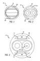
- FIG. 1is a front view of a schematic cross-sectional diagram of a first embodiment, illustrating a guiding catheter having a noncircular inner lumen and a round outer surface, showing the gaps or outer lumens between the noncircular inner walls and the round outer walls of the guiding catheter.
- FIG. 2is a front view of a schematic cross-sectional diagram of the guiding catheter of FIG. 1 , with two microcatheters within the noncircular inner lumen.
- FIG. 3is a front view of a schematic cross-sectional diagram illustrating elements and exemplary dimensions of the guiding catheter (with two microcatheters) of FIG. 2 .
- FIG. 4is a top view of a schematic diagram of the guiding catheter of FIG. 1 illustrating insertion of stiffening devices in the gaps or outer lumens between the noncircular inner walls and the round outer walls of the guiding catheter.
- FIG. 5is a side view of a schematic diagram of the guiding catheter of FIG. 4 .
- FIG. 6is a schematic cross-sectional diagram of the guiding catheter taken along line 6 - 6 of FIG. 5 .
- FIG. 7is a further detailed schematic cross-sectional diagram illustrating elements of the guiding catheter (with two microcatheters) of FIG. 2 .
- FIG. 8is an enlarged sectional view similar to FIG. 7 illustrating additional elements for the guiding catheter of FIG. 1 .
- FIG. 9is an isometric view of the guiding catheter of FIG. 1 .
- FIG. 10is a top view of a schematic diagram of a second embodiment of a guiding catheter with a noncircular inner lumen, and a round outer surface that does not extend the full length of the device.
- FIG. 11is a side view of a schematic diagram of the guiding catheter according to the second embodiment.
- FIG. 12is a schematic cross-sectional diagram of the guiding catheter taken along line 12 - 12 of FIG. 11 .
- FIG. 13is an isometric view of the guiding catheter according to the second embodiment.
- FIG. 14is an isometric view of a schematic diagram of the guiding catheter according to the second embodiment.
- FIG. 15is a schematic cross-sectional view of the guiding catheter of FIG. 10 similar to FIG. 12 including stiffening devices filling the gaps or outer lumens between the noncircular inner walls and the round outer walls of the guiding catheter.
- FIG. 16is an isometric view of the guiding catheter of FIG. 15 .
- FIG. 17is a schematic cross-sectional view of the guiding catheter of FIG. 10 similar to FIG. 12 including one stiffening device filling one of the gaps or outer lumens between the noncircular inner walls and the round outer walls of the guiding catheter.
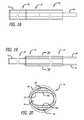
- FIG. 18is a top view of a schematic diagram similar to FIG. 10 illustrating insertion of stiffening devices in the gaps or outer lumens between the noncircular inner walls and the round outer walls of the guiding catheter.
- FIG. 19is a side view of a schematic diagram of the guiding catheter of FIG. 18 .
- FIG. 20is a schematic cross-sectional view of the guiding catheter taken along line 20 - 20 of FIG. 19 .
- FIG. 21is a schematic cross-sectional view of the guiding catheter of FIG. 10 similar to FIG. 12 including one hypotube stiffening device filling one of the gaps or outer lumens between the noncircular inner walls and the round outer walls of the guiding catheter.
- FIG. 22is an isometric view of a schematic diagram of a third embodiment of a guiding catheter having a round outer shape along the length of the device, with a proximal portion having an inner lumen with a noncircular shape, and a distal portion having an inner lumen with a round shape.
- FIG. 23is an isometric view of the guiding catheter of FIG. 22 .
- FIG. 24is an isometric broken away view of a schematic diagram of a guiding catheter in accordance with the present invention in which the guiding catheter has a segmented progressively compliant tip design.
- FIG. 25is a side view of a stiffening device that tapers along its length in accordance with the present invention.
- FIG. 26is a side view of a stiffening device comprised of different materials along its length in accordance with the present invention.
- FIG. 27is a side view of a stiffening device with a continuously changing taper angle in accordance with the present invention.
- FIG. 28is a side view of a stiffening device having contiguous tapered segments with different taper angles.
- FIG. 29is a schematic cross-sectional diagram of the guiding catheter in which the external wall has a coil or spring in it, in accordance with an embodiment of the present invention.
- FIG. 30A-Bare schematic diagrams of the catheter in a blood vessel showing the outer lumen as an inflation/deflation lumen for a balloon disposed on an outside of the catheter body in collapsed and expanded configurations.
- FIG. 31A-Dare schematic diagrams of the catheter in a blood vessel showing the expandable/collapsible metal cage disposed on an outside of the catheter body and actuated through control wires in the outer lumens in collapsed and expanded configurations with and without a distal membrane.
- FIG. 32is a schematic diagram of a liquid injected into the outer lumen in order to activate a layer or a segment of the wall structure of the guiding catheter body.
- FIG. 33is a schematic diagram of an electric heating element inserted into the outer lumen in order to activate a layer or a segment of the wall structure of the guiding catheter body.
- the present inventiongenerally provides for a noncircular inner lumen guiding catheter.
- the present inventionprovides for a noncircular inner lumen guiding catheter with assisted variable support 50 having a noncircular inner lumen wall 52 defining an inner lumen 54 having a noncircular cross-sectional shape for use in delivery of multiple microcatheters 56 a , 56 b for treatment of neurovascular defects, such as for treatment of aneurysms.
- the noncircular inner lumen guiding catheter with assisted variable support of the present inventionincludes torque transmittal guidance walls 58 a , 58 b that are flexible linearly but not circumferentially, and that are neither collapsible nor kinkable.
- the torque transmittal guidance wallsmay be made of a different material than the remainder of the guiding catheter wall structure as shown in FIG. 3 .
- the torque transmittal guidance wallsmay flex in a dimension perpendicular to a flat cross-sectional surface of the walls but may not flex in a dimension parallel to a flat cross-sectional surface of the walls.
- the outer surfacecan have a round outer wall 60 with a round cross-sectional shape, which typically extends from the proximal end or hub of the device to the distal end or tip, while the inner lumen remains noncircular. As is illustrated in FIGS.
- the inner lumencan be reinforced by a coil or braid 61 , and the braid can have a variable braid angle.
- the noncircular inner lumen guiding catheterpreferably also includes first and second gaps or outer lumens 62 a , 62 b , defined between the noncircular inner wall and the round outer wall of the guiding catheter (see FIGS. 3-5 , 7 , and 9 ).
- the round outer surface of the devicemay be composed of polymeric material segments progressively compliant that are configured to produce a linear change in stiffness over a longitudinal desired portion of the device.
- the external layeralso can be built in such a way that it has a free floating coil or spring 160 ( FIG. 29 ) constrained in it.
- This coil or springmay be affixed to the noncircular inner surface, while the other end is affixed to a push/pull mechanism that rides along the gaps or outer lumens between the noncircular inner surface and the outer surface 69 . Actuation of the mechanism will compress or extend the coil or spring. This action will stiffen or loosen/soften the catheter shaft.
- the gaps or outer lumens between the noncircular inner wall and the round outer wall of the guiding cathetermay be used as separate lumens for insertion or manipulation of one or more stiffening devices 64 that can help prevent the catheter from backing out of certain positions once inside the circulatory system.
- These stiffening devicesmay be composed of a round metal wire, a flat wire, a hypotube not conforming to the shape of the gap, a wire with the shape of the gap, or a hypotube with the shape of the gap.
- the stiffening devicesmay be made out of different materials (not limited to metals) and may change material along their length. For example, as shown in FIG.
- a stiffening device 150may have various sections 151 , 152 , 153 , 154 , 155 formed of different materials.
- the stiffening devicemay be a tapered stiffening device 140 that changes thickness or tapers along its length.
- the stiffening devicesmay have a section 142 with a continuously changing taper angle to produce a curvilinear profile that is configured to produce a linear change in stiffness of the catheter. As shown in FIG.
- the stiffening devicesmay have a section 144 of contiguous tapered segments 145 , 146 , 147 having taper angles that are configured to produce a linear change in stiffness over a longitudinal portion of the device.
- the stiffening devicesmay have a lubricious coating.
- one form of a stiffening devicecan be formed of a polymeric material conforming to the shape of a gap, including a central wire 65 , which can include an outer reinforcement 66 formed of a coil or braid, and can include a PTFE coating 67 .
- the stiffening devicesare preferably secured to the outside of the noncircular inner surface of the gap, but are free to move throughout the length of the device.
- the gaps or outer lumensalso may be used as separate lumens for insertion of push/pull mechanism elements to make the tip of the catheter deflectable.
- the catheter shaftpreferably is composed of a stainless and/or platinum braid/coil construction, with a lubricious inner lumen coating 68 of PTFE to optimize the wire exchange process in the most distal sections of the arteries.
- the proximal area(not shown) will have an ergonomically designed hub to allow the physician to easily manipulate the catheter as well the insertion of other medical devices.
- the present inventionprovides for a noncircular inner lumen guiding catheter with assisted variable support 70 having a noncircular inner lumen wall 72 defining an inner lumen 74 having a noncircular cross-sectional shape for use in delivery of multiple microcatheters for treatment of neurovascular defects, such as for treatment of aneurysms.
- the noncircular inner lumen guiding catheter with assisted variable support of the present inventionincludes torque transmittal guidance walls 78 a , 78 b that are flexible linearly but not circumferentially, and that are neither collapsible nor kinkable.
- the noncircular inner lumen guiding catheterincludes a distal portion 80 , and a proximal portion 82 also including a round outer wall 84 extending only a portion of the length of the guiding catheter, and an outer tapered transition wall 86 transitioning from the noncircular outer shape of the distal portion and the round outer shape of the proximal portion.
- the round outer surfacetypically stops somewhere along the length of the catheter, making a transition from a round proximal section to a noncircular distal section, with a noncircular lumen extending throughout the catheter.
- the noncircular lumen/wallmay make up the only lumen/wall in the distal portion and the inner lumen/wall in the proximal portion.
- First and second gaps or outer lumens 88 a , 88 bare defined between the noncircular inner wall and the proximal round outer wall of the guiding catheter as shown in FIGS. 12-15 , 17 , and 21 .
- the gaps or outer lumens 88 a , 88 b between the noncircular inner wall and the round outer wall of the guiding cathetermay be used as separate lumens for insertion or manipulation of one or more stiffening devices 90 that can help prevent the catheter from backing out of certain positions once inside the circulatory system.
- These stiffening devicesmay be composed of a round metal wire, a flat wire, a hypotube not conforming to the shape of the gap, a solid wire 92 with the shape of the gap, or a hypotube 94 with the shape of the gap.
- the stiffening devicesmay be made out of different materials (not limited to metals).
- the stiffening devicesmay have a section with a continuously changing taper angle to produce a curvilinear profile that is configured to produce a linear change in stiffness of the catheter.
- the stiffening devicesmay have a section of contiguous tapered segments having taper angles that are configured to produce a linear change in stiffness over a longitudinal portion of the device.
- the stiffening devicesmay have a lubricious coating.
- the stiffening devicesare preferably secured to the outside of the noncircular inner surface of the gap, but are free to move throughout the length of the device.
- a simple action by the user on the proximal endmay actuate them in such a way that one of them will be pushed while the other one will be pulled simultaneously provoking an increase in the overall stiffness of the proximal end of the catheter.
- the gaps or outer lumensalso may be used as separate lumen(s) for insertion of push/pull mechanism elements to make the tip of the catheter deflectable.
- the catheter shaftpreferably is composed of a stainless and/or platinum braid/coil construction, with a lubricious inner lumen coating 96 of PTFE to optimize the wire exchange process in the most distal sections of the arteries.
- the proximal area(not shown) will have an ergonomically designed hub to allow the physician to easily manipulate the catheter as well as to insert other medical devices.
- the exterior of the catheteris preferably covered with a polymer material 98 to encapsulate the stainless and/or platinum braid/coil construction.
- the polymer materialpreferably has a lubricious hydrophilic outer coating.
- the present inventionprovides for a noncircular inner lumen guiding catheter with assisted variable support 100 having a noncircular inner lumen wall 102 defining an inner lumen 104 having a noncircular cross-sectional shape for use in delivery of multiple microcatheters (not shown) for treatment of neurovascular defects, such as for treatment of aneurysms.
- the noncircular inner lumen guiding catheter with assisted variable support of the present inventionincludes torque transmittal guidance walls 108 a , 108 b that are flexible linearly but not circumferentially, and that are neither collapsible nor kinkable.
- the noncircular inner lumen guiding catheterincludes a distal portion 110 with a round outer wall 112 defining a round inner lumen 114 , and a proximal portion 116 also including a round outer wall 118 contiguous with the distal round outer wall.
- First and second gaps or outer lumens 120 a , 120 bare defined between the noncircular inner wall and the proximal round outer wall of the guiding catheter as shown in FIG. 22-23 .
- the deviceis reinforced with braid/coil and different polymer segments.
- the gaps or outer lumens between the noncircular inner wall and the round outer wall of the guiding cathetermay be used as separate lumens for insertion or manipulation of one or more stiffening devices (see stiffening device 64 in FIGS. 4-6 , central wire 65 in FIG. 8 , stiffening device 90 in FIGS. 10 , 15 - 20 , hypotube 94 in FIG. 21 , tapered stiffening device 140 in FIG. 25 , stiffening device 150 in FIG. 26 , tapered stiffening device 142 in FIG. 27 , and section of tapered segments 144 in FIG. 28 ) that can help prevent the catheter from backing out of certain positions once inside the circulatory system.
- stiffening devicessee stiffening device 64 in FIGS. 4-6 , central wire 65 in FIG. 8 , stiffening device 90 in FIGS. 10 , 15 - 20 , hypotube 94 in FIG. 21 , tapered stiffening device 140 in FIG. 25 , stiffening device 150 in FIG. 26 , tapered stiffening
- stiffening devicesmay be composed of a round metal wire, a flat wire, a hypotube not conforming to the shape of the gap, a wire with the shape of the gap, or a hypotube with the shape of the gap.
- the stiffening devicesmay be made out of different materials (not limited to metals).
- the stiffening devicesmay have a section with a continuously changing taper angle to produce a curvilinear profile that is configured to produce a linear change in stiffness of the catheter.
- the stiffening devicesmay have a section of contiguous tapered segments having taper angles that are configured to produce a linear change in stiffness over a longitudinal portion of the device.
- the stiffening devicesmay have a lubricious coating.
- the stiffening devicesare preferably secured to the outside of the noncircular inner surface of the gap, but are free to move throughout the length of the device. A simple action by the user on the proximal end will actuate them in such a way that one of them will be pushed while the other one will be pulled simultaneously provoking an increase in the overall stiffness of the proximal end of the catheter.
- the gaps or outer lumensalso may be used as separate lumen(s) for insertion of push/pull mechanism to make the tip of the catheter deflectable.
- the catheter shaftpreferably is composed of a stainless and/or platinum braid/coil construction, with a lubricious inner lumen coating 122 of PTFE to optimize the wire exchange process in the most distal sections of the arteries.
- the proximal areawill have an ergonomically designed hub to allow the physician to easily manipulate the catheter as well the insertion of other medical devices.
- the outer lumens formed between the noncircular inner lumen and the round outer surface of the cathetermay serve as inflation/deflation lumens for a polymer balloon 165 .
- the polymer balloonmay provide catheter proximal support or flow arrest during an interventional therapeutic procedure.
- the balloonmay be restricted to a proximal portion of the shaft to provide catheter proximal support or it may extend along a length or the entire length of the shaft.
- By supplying fluid to or suctioning fluid out of the outer inflation/deflation lumens the balloonmay be reversibly collapsed and expanded repetitively as needed.
- the balloonmay be anchored in place to provide and maintain flow arrest.
- the balloonmay be disposed on the outside of the catheter body or wall structure and communicates with outer inflation/deflation lumens that supply/suction fluid to the balloon through an opening in the outer catheter body or wall structure.
- the outer lumens between the noncircular inner lumen and the round outer surface of the catheter running along the substantially flat torque transmittal guidance wallsmay be used to run control wires to actuate a metal cage 170 .
- a version or a portion of the metal cagemay be used for device support at various desired positions along the length of the guiding catheter.
- a metal cage expanded through actuation of control wires within the outer lumens at the proximal end of the cathetermay provide proximal support to the catheter.
- a polymeric membrane 173may be provided in another version of the metal cage or in a restricted portion of the metal cage.
- the polymeric membranemay take the form of a silicone coating, for example.
- a polymeric membrane on the distal end of the metal cagemay be used for flow arrest.
- the metal cagemay be reversibly collapsed and expanded repetitively as needed, through actuation of control wires disposed in the outer lumens.
- the metal cagemay be actuated by control wires contained in the two small outer lumens in round jacketing.
- the outer lumensmay be used for injection of a liquid 175 therein. Injection of a liquid at a certain temperature into the outer lumens may serve to activate a desired polymer segment or polymer layer 177 on the catheter body.
- the outer lumensmay be used for insertion of an electric heating element 180 . Insertion of an electric heating element at a certain temperature into the outer lumens may serve to activate a desired polymer segment or polymer layer 177 on the catheter body.
- any of the embodimentsmay include a segmented progressively compliant tip design 130 ( FIG. 24 ) including microcatheters 36 a , 36 b contained in a catheter shaft 40 that incorporates a compliant polymeric material to minimize vessel trauma.
- the segmented progressively compliant tip design 130may comprises various segments 131 , 132 , 133 , 134 , 135 of different materials and/or the segments may be stepped such that the stiffness of the segmented progressively compliant distal tip 130 varies from one segment to the next.
- the exterior of the catheteris preferably covered with a polymer material to encapsulate the stainless and/or platinum braid/coil construction.
- the polymer materialpreferably has a lubricious hydrophilic outer coating.
Landscapes
- Health & Medical Sciences (AREA)
- Life Sciences & Earth Sciences (AREA)
- Heart & Thoracic Surgery (AREA)
- Veterinary Medicine (AREA)
- Engineering & Computer Science (AREA)
- Biomedical Technology (AREA)
- Animal Behavior & Ethology (AREA)
- General Health & Medical Sciences (AREA)
- Public Health (AREA)
- Anesthesiology (AREA)
- Hematology (AREA)
- Pulmonology (AREA)
- Biophysics (AREA)
- Surgery (AREA)
- Vascular Medicine (AREA)
- Nuclear Medicine, Radiotherapy & Molecular Imaging (AREA)
- Medical Informatics (AREA)
- Molecular Biology (AREA)
- Physics & Mathematics (AREA)
- Geometry (AREA)
- Reproductive Health (AREA)
- Child & Adolescent Psychology (AREA)
- Orthopedic Medicine & Surgery (AREA)
- Media Introduction/Drainage Providing Device (AREA)
- Surgical Instruments (AREA)
Abstract
Description
Claims (23)
Priority Applications (12)
| Application Number | Priority Date | Filing Date | Title |
|---|---|---|---|
| US13/088,314US8721588B2 (en) | 2011-04-15 | 2011-04-15 | Noncircular inner lumen guiding catheter with assisted variable support |
| AU2012202102AAU2012202102A1 (en) | 2011-04-15 | 2012-04-12 | Noncircular inner lumen guiding catheter with assisted variable support |
| KR1020120038440AKR102041091B1 (en) | 2011-04-15 | 2012-04-13 | Noncircular inner lumen guiding catheter with assisted variable support |
| EP12164143.5AEP2510971B1 (en) | 2011-04-15 | 2012-04-13 | Noncircular inner lumen guiding catheter with assisted variable support |
| ES12164143.5TES2485379T3 (en) | 2011-04-15 | 2012-04-13 | Non-circular interior light guide catheter with assisted variable support |
| CA2774733ACA2774733C (en) | 2011-04-15 | 2012-04-13 | Noncircular inner lumen guiding catheter with assisted variable support |
| CN201210115116.0ACN102727987B (en) | 2011-04-15 | 2012-04-13 | Non-circular interior tube chamber guiding catheter with assisted variable support member |
| JP2012091688AJP6071236B2 (en) | 2011-04-15 | 2012-04-13 | Non-circular inner lumen guide catheter with auxiliary variable support |
| BR102012008908-4ABR102012008908B1 (en) | 2011-04-15 | 2012-04-16 | guide catheter |
| US14/255,530US9669188B2 (en) | 2011-04-15 | 2014-04-17 | Noncircular inner lumen guiding catheter with assisted variable support |
| JP2016109826AJP6185113B2 (en) | 2011-04-15 | 2016-06-01 | Non-circular inner lumen guide catheter with auxiliary variable support |
| AU2017202455AAU2017202455B2 (en) | 2011-04-15 | 2017-04-13 | Noncircular inner lumen guiding catheter with assisted variable support |
Applications Claiming Priority (1)
| Application Number | Priority Date | Filing Date | Title |
|---|---|---|---|
| US13/088,314US8721588B2 (en) | 2011-04-15 | 2011-04-15 | Noncircular inner lumen guiding catheter with assisted variable support |
Related Child Applications (1)
| Application Number | Title | Priority Date | Filing Date |
|---|---|---|---|
| US14/255,530DivisionUS9669188B2 (en) | 2011-04-15 | 2014-04-17 | Noncircular inner lumen guiding catheter with assisted variable support |
Publications (2)
| Publication Number | Publication Date |
|---|---|
| US20120265134A1 US20120265134A1 (en) | 2012-10-18 |
| US8721588B2true US8721588B2 (en) | 2014-05-13 |
Family
ID=46000891
Family Applications (2)
| Application Number | Title | Priority Date | Filing Date |
|---|---|---|---|
| US13/088,314Active2031-07-27US8721588B2 (en) | 2011-04-15 | 2011-04-15 | Noncircular inner lumen guiding catheter with assisted variable support |
| US14/255,530Expired - Fee RelatedUS9669188B2 (en) | 2011-04-15 | 2014-04-17 | Noncircular inner lumen guiding catheter with assisted variable support |
Family Applications After (1)
| Application Number | Title | Priority Date | Filing Date |
|---|---|---|---|
| US14/255,530Expired - Fee RelatedUS9669188B2 (en) | 2011-04-15 | 2014-04-17 | Noncircular inner lumen guiding catheter with assisted variable support |
Country Status (9)
| Country | Link |
|---|---|
| US (2) | US8721588B2 (en) |
| EP (1) | EP2510971B1 (en) |
| JP (2) | JP6071236B2 (en) |
| KR (1) | KR102041091B1 (en) |
| CN (1) | CN102727987B (en) |
| AU (2) | AU2012202102A1 (en) |
| BR (1) | BR102012008908B1 (en) |
| CA (1) | CA2774733C (en) |
| ES (1) | ES2485379T3 (en) |
Cited By (12)
| Publication number | Priority date | Publication date | Assignee | Title |
|---|---|---|---|---|
| US9693865B2 (en) | 2013-01-09 | 2017-07-04 | 4 Tech Inc. | Soft tissue depth-finding tool |
| US9801720B2 (en) | 2014-06-19 | 2017-10-31 | 4Tech Inc. | Cardiac tissue cinching |
| US9907681B2 (en) | 2013-03-14 | 2018-03-06 | 4Tech Inc. | Stent with tether interface |
| US9907547B2 (en) | 2014-12-02 | 2018-03-06 | 4Tech Inc. | Off-center tissue anchors |
| US10039643B2 (en) | 2013-10-30 | 2018-08-07 | 4Tech Inc. | Multiple anchoring-point tension system |
| US10052095B2 (en) | 2013-10-30 | 2018-08-21 | 4Tech Inc. | Multiple anchoring-point tension system |
| US10058323B2 (en) | 2010-01-22 | 2018-08-28 | 4 Tech Inc. | Tricuspid valve repair using tension |
| US10206673B2 (en) | 2012-05-31 | 2019-02-19 | 4Tech, Inc. | Suture-securing for cardiac valve repair |
| US10238491B2 (en) | 2010-01-22 | 2019-03-26 | 4Tech Inc. | Tricuspid valve repair using tension |
| US10405978B2 (en) | 2010-01-22 | 2019-09-10 | 4Tech Inc. | Tricuspid valve repair using tension |
| WO2019226447A1 (en) | 2018-05-24 | 2019-11-28 | Edwards Lifesciences Corporation | Adjustable percutaneous heart valve repair system |
| US12017012B2 (en) | 2019-02-05 | 2024-06-25 | Bard Access Systems, Inc. | Apparatus and methods to modulate stylet stiffness profile |
Families Citing this family (32)
| Publication number | Priority date | Publication date | Assignee | Title |
|---|---|---|---|---|
| KR102308478B1 (en)* | 2013-03-15 | 2021-10-07 | 페이션트 센터드 메디칼 인코포레이티드 | Aspiration catheters, systems, and methods |
| US9561036B2 (en) | 2013-09-04 | 2017-02-07 | Rush University Medical Center | Catheter lumen partitioner |
| CN104740748B (en)* | 2013-12-31 | 2019-06-11 | 微创神通医疗科技(上海)有限公司 | A kind of guiding catheter |
| EP2977071A1 (en) | 2014-07-25 | 2016-01-27 | Cook Medical Technologies LLC | Supportive balloon catheter |
| JP6724131B2 (en)* | 2015-08-13 | 2020-07-15 | コーニンクレッカ フィリップス エヌ ヴェKoninklijke Philips N.V. | Catheter with optical sensing |
| JP2019531787A (en) | 2016-08-30 | 2019-11-07 | ザ リージェンツ オブ ザ ユニバーシティ オブ カリフォルニア | Biomedical targeting and delivery method and apparatus and system for performing the same |
| WO2018083905A1 (en)* | 2016-11-01 | 2018-05-11 | 株式会社カネカ | Catheter and catheter assembly |
| CN110430843B (en)* | 2017-03-14 | 2022-06-07 | 波士顿科学国际有限公司 | Medical device shaft including a liner |
| CN107174724A (en)* | 2017-05-08 | 2017-09-19 | 杭州唯强医疗科技有限公司 | A kind of controllable adjustable bent catheter of deflection distance |
| CN110650767B (en)* | 2017-05-26 | 2023-02-28 | 住友电木株式会社 | Catheter tube |
| CN111132626B (en) | 2017-07-17 | 2024-01-30 | 沃雅戈治疗公司 | track array guidance system |
| CN111093569B (en) | 2017-09-21 | 2023-03-31 | 泰尔茂株式会社 | Method for manufacturing stent delivery system and stent delivery system |
| CN111278497B (en) | 2017-11-28 | 2024-01-12 | 圣犹达医疗用品心脏病学部门有限公司 | Lumen control catheter |
| JP6951559B2 (en)* | 2018-04-26 | 2021-10-20 | オリンパス株式会社 | Treatment system and overtube |
| JP7244653B2 (en)* | 2018-09-21 | 2023-03-22 | クック・メディカル・テクノロジーズ・リミテッド・ライアビリティ・カンパニー | Introducer for uterine tamponade assembly with echogenic element and method of use |
| JP7410942B2 (en)* | 2018-10-29 | 2024-01-10 | キヤノン ユーエスエイ,インコーポレイテッド | Support structure for medical devices and manufacturing method thereof |
| US11957855B2 (en) | 2019-05-09 | 2024-04-16 | Neuravi Limited | Balloon guide catheter with positive venting of residual air |
| US11607531B2 (en) | 2019-05-09 | 2023-03-21 | Neuravi Limited | Balloon catheter with venting of residual air in a proximal direction |
| US11931522B2 (en) | 2019-05-09 | 2024-03-19 | Neuravi Limited | Inflation lumen kink protection and balloon profile |
| US11571553B2 (en) | 2019-05-09 | 2023-02-07 | Neuravi Limited | Balloon guide catheter with thermally expandable material |
| CN110193132B (en)* | 2019-05-17 | 2021-11-23 | 业聚医疗器械(深圳)有限公司 | Balloon catheter |
| US11202636B2 (en) | 2019-05-25 | 2021-12-21 | Galaxy Therapeutics Inc. | Systems and methods for treating aneurysms |
| US12102327B2 (en) | 2019-05-25 | 2024-10-01 | Galaxy Therapeutics, Inc. | Systems and methods for treating aneurysms |
| EP3982876B1 (en)* | 2019-06-12 | 2025-03-26 | Daniel Ezra Walzman | Orientable intracranial occlusion device |
| WO2021038560A1 (en)* | 2019-08-28 | 2021-03-04 | Valtech Cardio, Ltd. | Low-profile steerable catheter |
| CN114641334A (en)* | 2019-09-30 | 2022-06-17 | 阿比奥梅德公司 | Malleable sheath body |
| CN111588421B (en)* | 2020-05-29 | 2022-11-18 | 南方医科大学珠江医院 | Hepatobiliary surgery puncture equipment |
| US12016777B2 (en) | 2021-01-26 | 2024-06-25 | Boston Scientific Scimed, Inc. | Medical device including attachable components |
| US12396852B2 (en) | 2021-01-26 | 2025-08-26 | Boston Scientific Scimed, Inc. | Medical device including attachable components |
| WO2022164957A1 (en) | 2021-01-27 | 2022-08-04 | Galaxy Therapeutics, Inc. | Systems and methods for treating aneurysms |
| CN114796809A (en)* | 2022-03-30 | 2022-07-29 | 深圳市顺美医疗股份有限公司 | Balloon guide catheter |
| WO2024044290A2 (en)* | 2022-08-26 | 2024-02-29 | Deinde Medical Corp. | Endocisternal kit and method for creation of a cerebral third floor ventriculostomy using minimally invasive techniques |
Citations (24)
| Publication number | Priority date | Publication date | Assignee | Title |
|---|---|---|---|---|
| US4619643A (en) | 1983-07-25 | 1986-10-28 | Bai Chao Liang | Catheter |
| US5180368A (en) | 1989-09-08 | 1993-01-19 | Advanced Cardiovascular Systems, Inc. | Rapidly exchangeable and expandable cage catheter for repairing damaged blood vessels |
| US5487757A (en)* | 1993-07-20 | 1996-01-30 | Medtronic Cardiorhythm | Multicurve deflectable catheter |
| WO1996013296A1 (en) | 1994-11-01 | 1996-05-09 | Medical Innovations Corporation | Method and apparatus for electrosurgically obtaining access to the biliary tree and placing a stent therein |
| WO1997037716A1 (en) | 1996-04-10 | 1997-10-16 | Endoscopic Technologies, Inc. | Multichannel catheter |
| WO2001076655A2 (en) | 2000-04-06 | 2001-10-18 | Innercool Therapies, Inc. | Method and apparatus for regulating patient temperature by irrigating the bladder with a fluid |
| US6461336B1 (en) | 2000-02-08 | 2002-10-08 | LARRé JORGE CASADO | Cardiological medical equipment |
| US6562021B1 (en)* | 1997-12-22 | 2003-05-13 | Micrus Corporation | Variable stiffness electrically conductive composite, resistive heating catheter shaft |
| WO2003074107A2 (en) | 2002-03-01 | 2003-09-12 | Medtronic Minimed, Inc. | Multilumen catheter |
| US20040079429A1 (en)* | 2001-06-26 | 2004-04-29 | Concentric Medical, Inc. | Balloon catherer |
| US20050065469A1 (en) | 2003-09-24 | 2005-03-24 | Tal Michael G. | Method and apparatus for treatment of thrombosed hemodialysis access grafts |
| US6929626B2 (en)* | 2003-01-15 | 2005-08-16 | Scimed Life Systems, Inc. | Intraluminally placeable textile catheter, drain and stent |
| WO2005099802A2 (en) | 2004-04-19 | 2005-10-27 | Etview Ltd. | Imaging catheter |
| US20060270977A1 (en) | 2005-05-26 | 2006-11-30 | Conor Medsystems, Inc. | Rapid exchange balloon catheter with reinforced shaft |
| WO2006127929A2 (en) | 2005-05-23 | 2006-11-30 | Abbott Laboratories | Catheter having plurality of stiffening members |
| WO2007127176A2 (en) | 2006-04-24 | 2007-11-08 | Ekos Corporation | Ultrasound therapy system |
| US7344515B2 (en)* | 2004-09-17 | 2008-03-18 | Medtronic Vascular, Inc. | Guiding catheter with embolic protection by proximal occlusion |
| US20080147000A1 (en) | 2006-12-13 | 2008-06-19 | University Of Washington | Catheter tip displacement mechanism |
| US20080243176A1 (en)* | 2006-12-01 | 2008-10-02 | Barry Weitzner | Guide tube systems and methods |
| US20090124978A1 (en)* | 2003-12-10 | 2009-05-14 | Boston Scientific Scimed, Inc. | Modular steerable sheath catheters |
| WO2009065552A1 (en) | 2007-11-21 | 2009-05-28 | Iprm Intellectual Property Rights Management Ag | Medical tube |
| US7582079B2 (en)* | 2000-03-08 | 2009-09-01 | Boston Scientific Scimed, Inc. | Composite flexible tube for medical applications |
| US20090247868A1 (en)* | 2008-03-26 | 2009-10-01 | Medical Components, Inc. | Triple Lumen Catheter |
| WO2011015434A2 (en) | 2009-08-07 | 2011-02-10 | Peter Schlumpf | Protective sleeve for a catheter |
Family Cites Families (13)
| Publication number | Priority date | Publication date | Assignee | Title |
|---|---|---|---|---|
| CA1330285C (en)* | 1987-12-22 | 1994-06-21 | Geoffrey S. Martin | Triple lumen catheter |
| US4998917A (en)* | 1988-05-26 | 1991-03-12 | Advanced Cardiovascular Systems, Inc. | High torque steerable dilatation catheter |
| US5242396A (en)* | 1991-12-19 | 1993-09-07 | Advanced Cardiovascular Systems, Inc. | Dilatation catheter with reinforcing mandrel |
| US5246007A (en)* | 1992-03-13 | 1993-09-21 | Cardiometrics, Inc. | Vascular catheter for measuring flow characteristics and method |
| US5542937A (en)* | 1994-06-24 | 1996-08-06 | Target Therapeutics, Inc. | Multilumen extruded catheter |
| US5676653A (en)* | 1995-06-27 | 1997-10-14 | Arrow International Investment Corp. | Kink-resistant steerable catheter assembly |
| JP3775831B2 (en)* | 1995-09-22 | 2006-05-17 | テルモ株式会社 | Catheter tube |
| CA2409240C (en)* | 1996-11-26 | 2007-08-21 | Edwards Lifesciences Corporation | Multiple lumen access drive |
| US6887235B2 (en)* | 1999-03-24 | 2005-05-03 | Micrus Corporation | Variable stiffness heating catheter |
| US7041125B2 (en)* | 2002-07-01 | 2006-05-09 | Advanced Cardiovascular Systems, Inc. | Coil reinforced catheter inner tubular member |
| US8303569B2 (en)* | 2006-04-19 | 2012-11-06 | Medtronic Vascular, Inc. | Composite laminated catheter with flexible segment and method of making same |
| US8425406B2 (en)* | 2008-12-19 | 2013-04-23 | Boston Scientific Scimed, Inc. | Systems and methods for directing instruments to varying positions at the distal end of a guide tube |
| US8725228B2 (en)* | 2009-02-20 | 2014-05-13 | Boston Scientific Scimed, Inc. | Steerable catheter having intermediate stiffness transition zone |
- 2011
- 2011-04-15USUS13/088,314patent/US8721588B2/enactiveActive
- 2012
- 2012-04-12AUAU2012202102Apatent/AU2012202102A1/ennot_activeAbandoned
- 2012-04-13CNCN201210115116.0Apatent/CN102727987B/ennot_activeExpired - Fee Related
- 2012-04-13ESES12164143.5Tpatent/ES2485379T3/enactiveActive
- 2012-04-13JPJP2012091688Apatent/JP6071236B2/ennot_activeExpired - Fee Related
- 2012-04-13EPEP12164143.5Apatent/EP2510971B1/ennot_activeNot-in-force
- 2012-04-13CACA2774733Apatent/CA2774733C/ennot_activeExpired - Fee Related
- 2012-04-13KRKR1020120038440Apatent/KR102041091B1/ennot_activeExpired - Fee Related
- 2012-04-16BRBR102012008908-4Apatent/BR102012008908B1/ennot_activeIP Right Cessation
- 2014
- 2014-04-17USUS14/255,530patent/US9669188B2/ennot_activeExpired - Fee Related
- 2016
- 2016-06-01JPJP2016109826Apatent/JP6185113B2/ennot_activeExpired - Fee Related
- 2017
- 2017-04-13AUAU2017202455Apatent/AU2017202455B2/ennot_activeCeased
Patent Citations (25)
| Publication number | Priority date | Publication date | Assignee | Title |
|---|---|---|---|---|
| US4619643A (en) | 1983-07-25 | 1986-10-28 | Bai Chao Liang | Catheter |
| US5180368A (en) | 1989-09-08 | 1993-01-19 | Advanced Cardiovascular Systems, Inc. | Rapidly exchangeable and expandable cage catheter for repairing damaged blood vessels |
| US5487757A (en)* | 1993-07-20 | 1996-01-30 | Medtronic Cardiorhythm | Multicurve deflectable catheter |
| WO1996013296A1 (en) | 1994-11-01 | 1996-05-09 | Medical Innovations Corporation | Method and apparatus for electrosurgically obtaining access to the biliary tree and placing a stent therein |
| WO1997037716A1 (en) | 1996-04-10 | 1997-10-16 | Endoscopic Technologies, Inc. | Multichannel catheter |
| US6562021B1 (en)* | 1997-12-22 | 2003-05-13 | Micrus Corporation | Variable stiffness electrically conductive composite, resistive heating catheter shaft |
| US6461336B1 (en) | 2000-02-08 | 2002-10-08 | LARRé JORGE CASADO | Cardiological medical equipment |
| US7582079B2 (en)* | 2000-03-08 | 2009-09-01 | Boston Scientific Scimed, Inc. | Composite flexible tube for medical applications |
| WO2001076655A2 (en) | 2000-04-06 | 2001-10-18 | Innercool Therapies, Inc. | Method and apparatus for regulating patient temperature by irrigating the bladder with a fluid |
| US20040079429A1 (en)* | 2001-06-26 | 2004-04-29 | Concentric Medical, Inc. | Balloon catherer |
| WO2003074107A2 (en) | 2002-03-01 | 2003-09-12 | Medtronic Minimed, Inc. | Multilumen catheter |
| US6929626B2 (en)* | 2003-01-15 | 2005-08-16 | Scimed Life Systems, Inc. | Intraluminally placeable textile catheter, drain and stent |
| US20050065469A1 (en) | 2003-09-24 | 2005-03-24 | Tal Michael G. | Method and apparatus for treatment of thrombosed hemodialysis access grafts |
| US20090124978A1 (en)* | 2003-12-10 | 2009-05-14 | Boston Scientific Scimed, Inc. | Modular steerable sheath catheters |
| WO2005099802A2 (en) | 2004-04-19 | 2005-10-27 | Etview Ltd. | Imaging catheter |
| US7344515B2 (en)* | 2004-09-17 | 2008-03-18 | Medtronic Vascular, Inc. | Guiding catheter with embolic protection by proximal occlusion |
| WO2006127929A2 (en) | 2005-05-23 | 2006-11-30 | Abbott Laboratories | Catheter having plurality of stiffening members |
| US20060270977A1 (en) | 2005-05-26 | 2006-11-30 | Conor Medsystems, Inc. | Rapid exchange balloon catheter with reinforced shaft |
| WO2007127176A2 (en) | 2006-04-24 | 2007-11-08 | Ekos Corporation | Ultrasound therapy system |
| US20080243176A1 (en)* | 2006-12-01 | 2008-10-02 | Barry Weitzner | Guide tube systems and methods |
| US20080147000A1 (en) | 2006-12-13 | 2008-06-19 | University Of Washington | Catheter tip displacement mechanism |
| WO2009065552A1 (en) | 2007-11-21 | 2009-05-28 | Iprm Intellectual Property Rights Management Ag | Medical tube |
| US20090247868A1 (en)* | 2008-03-26 | 2009-10-01 | Medical Components, Inc. | Triple Lumen Catheter |
| WO2009120871A2 (en) | 2008-03-26 | 2009-10-01 | Medical Components, Inc. | Triple lumen catheter |
| WO2011015434A2 (en) | 2009-08-07 | 2011-02-10 | Peter Schlumpf | Protective sleeve for a catheter |
Non-Patent Citations (1)
| Title |
|---|
| European Search Report, Sep. 12, 2012, 11 pages. |
Cited By (17)
| Publication number | Priority date | Publication date | Assignee | Title |
|---|---|---|---|---|
| US10058323B2 (en) | 2010-01-22 | 2018-08-28 | 4 Tech Inc. | Tricuspid valve repair using tension |
| US10433963B2 (en) | 2010-01-22 | 2019-10-08 | 4Tech Inc. | Tissue anchor and delivery tool |
| US10405978B2 (en) | 2010-01-22 | 2019-09-10 | 4Tech Inc. | Tricuspid valve repair using tension |
| US10238491B2 (en) | 2010-01-22 | 2019-03-26 | 4Tech Inc. | Tricuspid valve repair using tension |
| US10206673B2 (en) | 2012-05-31 | 2019-02-19 | 4Tech, Inc. | Suture-securing for cardiac valve repair |
| US10449050B2 (en) | 2013-01-09 | 2019-10-22 | 4 Tech Inc. | Soft tissue depth-finding tool |
| US9788948B2 (en) | 2013-01-09 | 2017-10-17 | 4 Tech Inc. | Soft tissue anchors and implantation techniques |
| US9693865B2 (en) | 2013-01-09 | 2017-07-04 | 4 Tech Inc. | Soft tissue depth-finding tool |
| US9907681B2 (en) | 2013-03-14 | 2018-03-06 | 4Tech Inc. | Stent with tether interface |
| US10052095B2 (en) | 2013-10-30 | 2018-08-21 | 4Tech Inc. | Multiple anchoring-point tension system |
| US10039643B2 (en) | 2013-10-30 | 2018-08-07 | 4Tech Inc. | Multiple anchoring-point tension system |
| US9801720B2 (en) | 2014-06-19 | 2017-10-31 | 4Tech Inc. | Cardiac tissue cinching |
| US9907547B2 (en) | 2014-12-02 | 2018-03-06 | 4Tech Inc. | Off-center tissue anchors |
| US11389152B2 (en) | 2014-12-02 | 2022-07-19 | 4Tech Inc. | Off-center tissue anchors with tension members |
| WO2019226447A1 (en) | 2018-05-24 | 2019-11-28 | Edwards Lifesciences Corporation | Adjustable percutaneous heart valve repair system |
| US11007061B2 (en) | 2018-05-24 | 2021-05-18 | Edwards Lifesciences Corporation | Adjustable percutaneous heart valve repair system |
| US12017012B2 (en) | 2019-02-05 | 2024-06-25 | Bard Access Systems, Inc. | Apparatus and methods to modulate stylet stiffness profile |
Also Published As
| Publication number | Publication date |
|---|---|
| AU2012202102A1 (en) | 2012-11-01 |
| JP6185113B2 (en) | 2017-08-23 |
| CA2774733C (en) | 2019-06-18 |
| JP2012223578A (en) | 2012-11-15 |
| AU2017202455B2 (en) | 2019-02-21 |
| KR102041091B1 (en) | 2019-11-06 |
| JP6071236B2 (en) | 2017-02-01 |
| BR102012008908B1 (en) | 2021-01-26 |
| US20140228749A1 (en) | 2014-08-14 |
| ES2485379T3 (en) | 2014-08-13 |
| CN102727987A (en) | 2012-10-17 |
| US20120265134A1 (en) | 2012-10-18 |
| US9669188B2 (en) | 2017-06-06 |
| BR102012008908A2 (en) | 2017-10-10 |
| EP2510971A1 (en) | 2012-10-17 |
| CN102727987B (en) | 2018-03-30 |
| CA2774733A1 (en) | 2012-10-15 |
| AU2017202455A1 (en) | 2017-05-04 |
| JP2016172059A (en) | 2016-09-29 |
| EP2510971B1 (en) | 2014-05-14 |
| KR20120117674A (en) | 2012-10-24 |
Similar Documents
| Publication | Publication Date | Title |
|---|---|---|
| US8721588B2 (en) | Noncircular inner lumen guiding catheter with assisted variable support | |
| US12329914B2 (en) | Transcarotid neurovascular catheter | |
| US5573508A (en) | Catheter with an expandable perfusion lumen | |
| CA2796951C (en) | Low profile guiding catheter for neurovascular applications | |
| US8043257B2 (en) | Agent delivery catheter having an inflation bridge between two axially spaced balloons | |
| US7993303B2 (en) | Stiffening support catheter and methods for using the same | |
| US5573509A (en) | Catheter with an expandable perfusion slit | |
| EP3174591B1 (en) | Transcarotid neurovascular catheter | |
| CN109862835A (en) | Clot retrieval system for removing an occluded clot from a blood vessel | |
| JP2013066720A (en) | Distal access balloon guide catheter | |
| JP2016165407A (en) | Baloon catheter | |
| JP2009022432A (en) | Guiding catheter | |
| US20230071144A1 (en) | Radial access balloon catheter |
Legal Events
| Date | Code | Title | Description |
|---|---|---|---|
| AS | Assignment | Owner name:MICRUS ENDOVASCULAR LLC, CALIFORNIA Free format text:ASSIGNMENT OF ASSIGNORS INTEREST;ASSIGNORS:ECHARRI, ROBERTO;TAYLOR, CLIFFORD D.;WILLIAMS, ERIC;SIGNING DATES FROM 20110614 TO 20110615;REEL/FRAME:026456/0650 | |
| AS | Assignment | Owner name:DEPUY SPINE, LLC, MASSACHUSETTS Free format text:ASSIGNMENT OF ASSIGNORS INTEREST;ASSIGNOR:CODMAN & SHURTLEFF, INC.;REEL/FRAME:030352/0987 Effective date:20121230 Owner name:DEPUY SYNTHES PRODUCTS, LLC, MASSACHUSETTS Free format text:CHANGE OF NAME;ASSIGNOR:HAND INNOVATIONS LLC;REEL/FRAME:030353/0083 Effective date:20121231 Owner name:HAND INNOVATIONS LLC, FLORIDA Free format text:ASSIGNMENT OF ASSIGNORS INTEREST;ASSIGNOR:DEPUY SPINE, LLC;REEL/FRAME:030353/0075 Effective date:20121230 Owner name:CODMAN & SHURTLEFF, INC., MASSACHUSETTS Free format text:ASSIGNMENT OF ASSIGNORS INTEREST;ASSIGNOR:MICRUS ENOVASCULAR LLC;REEL/FRAME:030352/0972 Effective date:20121230 | |
| STCF | Information on status: patent grant | Free format text:PATENTED CASE | |
| AS | Assignment | Owner name:CODMAN & SHURTLEFF, INC., MASSACHUSETTS Free format text:CORRECTIVE ASSIGNMENT TO CORRECT THE REMOVE SERIAL NUMBER 12/554,588 PREVIOUSLY RECORDED ON REEL 030352 FRAME 0973. ASSIGNOR(S) HEREBY CONFIRMS THE ASSIGNMENT;ASSIGNOR:MICRUS ENDOVASCULAR LLC;REEL/FRAME:034535/0733 Effective date:20121230 | |
| AS | Assignment | Owner name:DEPUY SYNTHES PRODUCTS, INC., MASSACHUSETTS Free format text:CHANGE OF NAME;ASSIGNOR:DEPUY SYNTHES PRODUCTS, LLC;REEL/FRAME:036923/0199 Effective date:20141219 | |
| MAFP | Maintenance fee payment | Free format text:PAYMENT OF MAINTENANCE FEE, 4TH YEAR, LARGE ENTITY (ORIGINAL EVENT CODE: M1551) Year of fee payment:4 | |
| MAFP | Maintenance fee payment | Free format text:PAYMENT OF MAINTENANCE FEE, 8TH YEAR, LARGE ENTITY (ORIGINAL EVENT CODE: M1552); ENTITY STATUS OF PATENT OWNER: LARGE ENTITY Year of fee payment:8 |