US8721553B2 - Fluid-fillable ultrasound imaging catheter tips - Google Patents
Fluid-fillable ultrasound imaging catheter tipsDownload PDFInfo
- Publication number
- US8721553B2 US8721553B2US12/104,223US10422308AUS8721553B2US 8721553 B2US8721553 B2US 8721553B2US 10422308 AUS10422308 AUS 10422308AUS 8721553 B2US8721553 B2US 8721553B2
- Authority
- US
- United States
- Prior art keywords
- catheter tip
- imaging catheter
- motor
- transducer
- imaging
- Prior art date
- Legal status (The legal status is an assumption and is not a legal conclusion. Google has not performed a legal analysis and makes no representation as to the accuracy of the status listed.)
- Expired - Fee Related, expires
Links
Images


Classifications
- A—HUMAN NECESSITIES
- A61—MEDICAL OR VETERINARY SCIENCE; HYGIENE
- A61B—DIAGNOSIS; SURGERY; IDENTIFICATION
- A61B8/00—Diagnosis using ultrasonic, sonic or infrasonic waves
- A61B8/44—Constructional features of the ultrasonic, sonic or infrasonic diagnostic device
- A61B8/4444—Constructional features of the ultrasonic, sonic or infrasonic diagnostic device related to the probe
- A61B8/4461—Features of the scanning mechanism, e.g. for moving the transducer within the housing of the probe
- A—HUMAN NECESSITIES
- A61—MEDICAL OR VETERINARY SCIENCE; HYGIENE
- A61B—DIAGNOSIS; SURGERY; IDENTIFICATION
- A61B8/00—Diagnosis using ultrasonic, sonic or infrasonic waves
- A61B8/12—Diagnosis using ultrasonic, sonic or infrasonic waves in body cavities or body tracts, e.g. by using catheters
- A—HUMAN NECESSITIES
- A61—MEDICAL OR VETERINARY SCIENCE; HYGIENE
- A61B—DIAGNOSIS; SURGERY; IDENTIFICATION
- A61B8/00—Diagnosis using ultrasonic, sonic or infrasonic waves
- A61B8/42—Details of probe positioning or probe attachment to the patient
- A61B8/4272—Details of probe positioning or probe attachment to the patient involving the acoustic interface between the transducer and the tissue
- A61B8/4281—Details of probe positioning or probe attachment to the patient involving the acoustic interface between the transducer and the tissue characterised by sound-transmitting media or devices for coupling the transducer to the tissue
- A—HUMAN NECESSITIES
- A61—MEDICAL OR VETERINARY SCIENCE; HYGIENE
- A61B—DIAGNOSIS; SURGERY; IDENTIFICATION
- A61B8/00—Diagnosis using ultrasonic, sonic or infrasonic waves
- A61B8/44—Constructional features of the ultrasonic, sonic or infrasonic diagnostic device
- A61B8/4444—Constructional features of the ultrasonic, sonic or infrasonic diagnostic device related to the probe
- A61B8/445—Details of catheter construction
- A—HUMAN NECESSITIES
- A61—MEDICAL OR VETERINARY SCIENCE; HYGIENE
- A61B—DIAGNOSIS; SURGERY; IDENTIFICATION
- A61B8/00—Diagnosis using ultrasonic, sonic or infrasonic waves
- A61B8/48—Diagnostic techniques
- A61B8/483—Diagnostic techniques involving the acquisition of a 3D volume of data
Definitions
- the present disclosurerelates generally to ultrasound imaging and, more particularly, to imaging catheter tips which contain acoustic transducers for obtaining ultrasound images.
- Acoustic transducershave found application in medical imaging where an acoustic probe is held against a patient and the probe transmits and receives ultrasound waves. The received energy may, in turn, facilitate the imaging of the tissues of the patient. For example, transducers may be employed to image the heart of the patient.
- Catheter-based ultrasonic imaging techniquesare interventional procedures that generally involve inserting a probe, such as an imaging catheter, into a vein, such as the femoral vein, or an artery.
- catheter-based ultrasonic imaging techniquesmay be employed for imaging the heart, such as when monitoring and/or directing treatment of atrial fibrillation. Consequently, it is highly desirable that transducer assemblies used in catheters be capable of two-dimensional and/or real-time three-dimensional imaging. Such applications are quite demanding, requiring very small transducer packages that can nevertheless collect large amounts of information.
- transducer packagethat is mechanically, acoustically, and electrically suitable. Therefore, it may be desirable to provide a transducer probe assembly suitable for interventional imaging that has acceptable mechanical, electrical, and/or acoustic characteristics.
- an imaging catheter tipincludes a housing. Further, the imaging catheter tip includes a transducer assembly located within the housing in a distal portion of the imaging catheter tip. The transducer assembly includes a transducer. In addition, the imaging catheter tip includes a motor located within the housing in a proximal portion of the imaging catheter tip. The motor is configured to facilitate oscillation of the transducer assembly about a longitudinal axis of the imaging catheter tip. The imaging catheter tip also includes a fill tube disposed between the motor and the housing. The fill tube is configured to deliver acoustic coupling fluid to the distal portion of the imaging catheter tip.
- the imaging catheter tipincludes a housing. Further, the imaging catheter tip includes a transducer located within the housing in a distal portion of the imaging catheter tip. In addition, the imaging catheter tip includes a motor assembly located within the housing in a proximal portion of the imaging catheter tip. The motor assembly includes a motor holder and a motor configured to facilitate oscillation of the transducer about a longitudinal axis of the imaging catheter tip. The imaging catheter tip also includes a flexible interconnect cable disposed between the motor assembly and the housing. The flexible interconnect cable is configured to connect to the transducer.
- a method of using an imaging catheter tipincludes filling a distal portion of the imaging catheter tip with acoustic coupling fluid from a proximal end of the imaging catheter tip using a fill tube. The method also includes inserting the imaging catheter tip into a patient. The method further includes collecting ultrasound imaging data using a transducer assembly disposed in the distal portion of the imaging catheter tip.
- a method of initializing the oscillation of a transducer assembly within an imaging catheter tipincludes rotating the transducer assembly in a first rotational direction about an axis of rotation until a hard stop is contacted.
- the methodalso includes determining a first rotational location indicative of the location of the hard stop.
- the methodfurther includes rotating the transducer assembly about the axis of rotation based on at least the first rotational location.
- a systemin accordance with further aspects of the present technique, includes an imaging system for collecting imaging data and an imaging catheter.
- the imaging catheterincludes an imaging catheter tip.
- the imaging catheter tipincludes a transducer assembly located in a distal portion of the imaging catheter tip.
- the imaging catheter tipalso includes a motor assembly located in a proximal portion of the imaging catheter tip.
- the imaging catheter tipincludes a fill tube configured to fill the distal portion of the imaging catheter tip with fluid from a proximal end of the imaging catheter tip.
- FIG. 1is a block diagram of an exemplary ultrasound imaging system, in accordance with aspects of the present technique
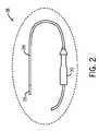
- FIG. 2is a side view of a portion of an invasive probe including an exemplary imaging catheter tip and transducer assembly for use in the system illustrated in FIG. 1 , in accordance with aspects of the present technique;
- FIG. 3is a perspective side view of an exemplary embodiment of an imaging catheter tip, in accordance with aspects of the present technique
- FIG. 4is a perspective side view of another exemplary embodiment of an imaging catheter tip, in accordance with aspects of the present technique.
- FIG. 5is a perspective side view of yet another exemplary embodiment of an imaging catheter tip, in accordance with aspects of the present technique.
- Imaging probes containing transducer assemblies for obtaining real-time, three-dimensional ultrasound imagingmay use a motor assembly to oscillate transducer assemblies about an axis of the imaging probe. In doing so, the transducer assemblies may be capable of obtaining real-time, three-dimensional ultrasound images by sweeping a two-dimensional slice through a three-dimensional volume. Acoustic coupling fluid may be used in conjunction with the transducer assemblies to provide an effective or suitable acoustic transition between the transducer and the surrounding housing.
- imaging probesare typically filled with acoustic coupling fluid at the time of manufacture.
- Such imaging probesalso typically include a fluid barrier to separate the motor from the fluid-filled space that houses the transducer. The barrier is penetrated by a driveshaft that couples the motor to the moving transducer. A fluid seal on the driveshaft prevents or minimizes the leakage of fluid from the transducer space to the motor space.
- the space constraintsmay preclude isolating the motor from the fluid-filled transducer space.
- the presence of the acoustic coupling fluid in the imaging catheter tip for long periods of time before usemay prove problematic.
- the fluidmay gradually seep into the motor and associated gearbox, increasing the risk of performance degradation.
- the risk of shelf-life failuresmay be increased.
- corrosion and leachingmay occur since the fluid is encased in the imaging catheter tip for such a long period of time.
- sterilizationmay be more difficult when filling the imaging catheter tip at the time of manufacture.
- imaging catheter tipsare filled from the distal end of the imaging catheter tip. This may prove problematic in that the imaging catheter tip may not be properly sealed after filling.
- many typical methods for filling the imaging catheter tiphave a tendency to generate bubbles in the acoustic coupling fluid which can cause problems during image data collection.
- an imaging catheter tip with a transducer assemblycapable of real-time, three-dimensional imaging for use in an invasive probe employed in space critical applications such as intracardiac imaging.
- the system and methods presentedallow for filling of the imaging catheter tip with acoustic coupling fluid at the time of use.
- the imaging catheter tipincorporates fill and vent tubes and other specific features which may minimize trapped bubbles in the imaging catheter tip during fluid filling.
- the imaging catheter tipmay also include one or more hard stop mechanisms allowing for multiple ranges of oscillatory motion of the transducer assembly.
- the imaging catheter tipmay allow for an increased length of the rotatable interconnect cable, reducing the torque, power, and temperature requirements of the motor assembly used to oscillate the transducer assembly.
- filling at the time of usemay reduce the risk of performance degradation associated with fluid incursion into the motor and associated gearbox as compared to filling at the time of manufacture. Since the acoustic coupling fluid may be introduced into the imaging catheter tip only a short while before use, there may be considerably less chance of the fluid leaking into these components to such a degree that their performance will be adversely affected. For similar reasons, the risk of shelf-life failures due to fluid-component interactions may also be reduced.
- the present techniquemay cause improved biocompatibility due to the fact that there may be less time for leaching and corrosion to occur.
- sterilizationmay be easier using the present technique since ethylene oxide gas sterilization may be utilized.
- the fact that the distal tip may be closed, compared to a design requiring filling from the distal endmay lead to increased safety.
- Another advantagemay include the ability to integrate the imaging catheter tip with any manufacturer's catheter due to the self-contained nature of the imaging catheter tip.
- FIG. 1is a block diagram of an exemplary system 10 for use in ultrasound imaging, in accordance with aspects of the present technique.
- the system 10may be configured to facilitate acquisition of ultrasound image data from a patient 12 via an imaging catheter 14 .
- the imaging catheter 14may be configured to acquire ultrasound image data representative of a region of interest in the patient 12 .
- the imaging catheter 14may be configured to function as an invasive probe.
- Reference numeral 16is representative of a portion of the imaging catheter 14 disposed inside the patient 12 , such as inserted into a vein.
- Reference numeral 18is indicative of a portion of the imaging catheter 14 depicted in greater detail in FIG. 2 .
- the system 10may also include an ultrasound imaging system 20 that is in operative association with the imaging catheter 14 and configured to facilitate acquisition of ultrasound image data.
- an ultrasound imaging system 20that is in operative association with the imaging catheter 14 and configured to facilitate acquisition of ultrasound image data.
- other imaging systems and applicationsare also contemplated (e.g., industrial applications, such as non-destructive testing, borescopes, and other applications where ultrasound imaging within confined spaces may be used). Additionally, the exemplary embodiments illustrated and described hereinafter may find application in multi-modality imaging systems that employ ultrasound imaging in conjunction with other imaging modalities, position-tracking systems, or other sensor systems.
- the ultrasound imaging system 20may be configured to display an image representative of a current position of the imaging catheter 14 within the patient 12 .
- the ultrasound imaging system 20may include a display area 22 and a user interface area 24 .
- the display area 22 of the ultrasound imaging system 20may be configured to display a two- or three-dimensional image generated by the ultrasound imaging system 20 based on the image data acquired via the imaging catheter 14 .
- the display area 22may be a suitable CRT or LCD display on which ultrasound images may be viewed.
- the user interface area 24may include an operator interface device configured to aid the operator in identifying a region of interest to be imaged.
- the operator interfacemay include a keyboard, mouse, trackball, joystick, touch screen, or any other suitable interface device.
- FIG. 2illustrates an enlarged view of the portion 18 (see FIG. 1 ) of the imaging catheter 14 (see FIG. 1 ).
- the imaging catheter 14may include a tip 26 on the distal end of a flexible shaft 28 . It is this distal tip 26 that houses the transducer assembly and motor assembly as discussed herein.
- the imaging catheter 14may also include a handle 30 configured to facilitate an operator manipulating the flexible shaft 28 .
- points within the imaging catheter 14 which are closer to the handle 30may be referred to as proximal whereas points within the imaging catheter which are further from the handle 30 may be referred to as distal.
- the distance between the transducer assembly and the handle 30may be in a range from about 10 cm to about 150 cm depending on the type of probe and application.
- FIG. 3depicts an exemplary embodiment of an imaging catheter tip 26 .
- the imaging catheter tip 26includes a housing 32 which contains, among other things, a motor 34 , a motor holder 36 , a transducer 38 , and a transducer holder 40 , and, optionally, a lens 42 .
- Similar imaging catheter tipsare described in U.S. Patent Application Publication Nos. 2007/0167813 filed on Jan. 18, 2007, 2007/0167821 filed on Nov. 30, 2005, 2007/0167824 filed on Jan. 11, 2006, 2007/0167825 filed on Jan. 11, 2006, and 2007/0167826 filed on Jan. 11, 2006, each to Warren Lee at al. as well as U.S. patent application Ser. No.
- the motor 34may be used to oscillate the transducer 38 about an axis 44 .
- the transducer 38may, for example, be a 64-element phased array and may be oscillated about the axis 44 in order to generate real-time, three dimensional imaging by sweeping a two-dimensional slice over a three-dimensional volume.
- the motor 34may be controlled by a motor controller external to the imaging catheter tip 26 .
- the motor controllermay be incorporated as part of the handle 30 or ultrasound imaging system 20 .
- the motor 34may, in certain embodiments, be configured for low torque and low speeds since the motor 34 may only be required to oscillate the transducer 38 through a limited range of angular motion, for instance, 90-180 degrees of rotation. However, the motor 34 may also be a high-precision motor in that the imaging carried out by the transducer 38 and associated lens 42 may require precise oscillation.
- the motor holder 36may serve several purposes with respect to the motor 34 .
- the motor holder 36may serve to fix the motor in a specific position (e.g. centered relative to axis 44 ).
- the motor holder 36may serve to support or constrain other components of the imaging catheter tip 26 .
- the motor holder 36may support a thermistor 48 , a fill tube 50 , a vent tube 56 , the proximal end of the flexible interconnect cable 46 , and other components.
- the motor holder 36may serve as a bulkhead to minimize the adverse effects of an acoustic coupling fluid filling back into the proximal portion of the imaging catheter tip 26 .
- the motor holder 36may act as protection for other components within and outside the imaging catheter tip 26 from the motor 34 .
- the motor 34may generate heat even from the minimal oscillations required for imaging.
- the motor holder 36may be made of a material with a high thermal conductivity, to help distribute the motor heat over a greater length of the imaging catheter tip 26 .
- the motor holder 36may be made of a material with a low thermal conductivity, to minimize the transfer of heat from the motor 34 to the housing 32 , where it could create hot spots that could potentially be injurious to a patient.
- the motor holder 36may be made of an anisotropic or composite material with high thermal conductivity in a longitudinal direction (e.g., parallel to axis 44 ) and low thermal conductivity in transverse directions (e.g., radial to the imaging catheter 14 or perpendicular to axis 44 ) so as to both distribute heat along the imaging catheter tip 26 and reduce direct transfer of heat to the catheter housing 32 .
- a thermistor 48may be used to monitor the temperature of the motor 34 and motor holder 36 .
- the thermistor 48may send information to the ultrasound imaging system 20 which may, in turn, take appropriate actions when the thermistor 48 senses that the internal temperature of the imaging catheter tip 26 has reached a predetermined level. For instance, the ultrasound imaging system 20 may automatically place restrictions on how fast subsequent imaging may take place. By restricting the ultrasound imaging system 20 in such a way, subsequent heat generation may be minimized.
- the ultrasound imaging system 20may report to the operator of the ultrasound imaging system 20 that excessive temperatures have been reached. In this manner, the operator may take appropriate corrective measures.
- the imaging catheter tip 26may be filled with acoustic coupling fluid at or near the time of use of the imaging catheter tip 26 .
- the imaging catheter tip 26may be filled during or immediately prior to an examination in which the imaging catheter tip 26 is used to collect imaging data.
- the imaging catheter tip 26may be filled at the examination site such as at a clinic, hospital, or doctor's office.
- the imaging catheter tip 26may be filled within a certain number of hours (e.g., one, two, . . . , eight, or twelve hours, and so forth) before use.
- the imaging catheter tip 26 of the present techniqueis typically filled after manufacture and shipping of the imaging catheter tip 26 .
- a fill tube 50may be used to deliver an acoustic coupling fluid into a distal portion of the imaging catheter tip 26 from the proximal end of the imaging catheter tip 26 at or near the time of use of the imaging catheter tip 26 .
- an acoustically suitable coupling fluidit may be possible to exclude the lens 42 and use only the transducer 38 for imaging. Advantages of excluding the lens 42 may include a more simplified design, greater signal-to-noise ratio due to less lens attenuation, and less friction with which to load the motor 34 .
- Such an acoustic coupling fluidmay have one or more of the following properties: (1) sound velocity and density similar to water, (2) low tendency for releasing gas (in order to minimize bubbles from forming after filling), (3) biocompatibility, (4) the ability to wet the inner surfaces of the imaging catheter tip 26 , and so forth.
- Several fluidshave been tested and identified as possible candidates for the acoustic coupling fluid. These fluids include: (1) propylene glycol, (2) water, (3) ethanol, (4) polyethylene glycol, (5) 3M FC-3283 Fluorinert, and so forth. Other fluids may also prove suitable as this list is merely meant to be illustrative.
- the acoustic coupling fluidmay be introduced by the fill tube 50 at the fill port 52 .
- the fill port 52may be located near the proximal end of the transducer holder 40 .
- the distal portion of the imaging catheter tip 26is filled while the distal end of the imaging catheter tip 26 is pointing downward.
- the acoustic coupling fluidmay fill the distal portion of the imaging catheter tip 26 through capillary action between the transducer 38 (and lens 42 , if used) and the housing 32 of the imaging catheter tip 26 .
- the acoustic coupling fluidmay fill the distal portion of the imaging catheter tip 26 until the entire portion is filled.
- the fill tube 50may be a metal tube or other rigid tube that may function as part of the hard stop mechanism, as discussed in greater detail below.
- the fill tube 50may be required to be somewhat flexible. Therefore, the fill tube 50 may be a combination of a rigid tube in the imaging catheter tip 26 coupled to a long, flexible tube through the flexible shaft 28 .
- the fill tube 50may be a discrete tube inserted into a larger lumen in the catheter.
- the fill tube 50may be one, or possibly more, lumens integrated into the catheter construction.
- the fill tube 50provides a leak-tight, pressure-capable connection to the imaging catheter tip 26 and the fill port 52 .
- a vent 54may be used at the distal end of the transducer holder 40 . This vent 54 may facilitate the removal of the bubbles. It may also be possible for the operator of the imaging catheter tip 26 to use a simple “lasso” motion to force the bubbles to be removed through a vent tube 56 in response to centripetal forces. In other words, the vent 54 and vent tube 56 give the bubbles a route through which to exit the imaging catheter tip 26 .
- the vent tube 56which may receive expelled air and excess acoustic coupling fluid from the imaging catheter tip 26 , may be similar to the fill tube 50 or may also be part of a lumen in the catheter.
- the vent tube 56should also be leak-tight, but does not necessarily have to be able of sustaining high pressures, depending on the embodiment. In other embodiments, the expelled air and excess acoustic coupling fluid may simply pass around the other components in the imaging catheter tip 26 , such as the signal cables and wiring.
- both tubes 50 and 56may be closed.
- FIG. 4is a perspective side view of another exemplary embodiment of an imaging catheter tip 26 .
- This illustrated embodimentis conceptually similar to the embodiment shown in FIG. 3 .
- the fill tube 50may extend to the distal end of the imaging catheter tip 26 .
- the acoustic coupling fluidmay fill the imaging catheter tip 26 from the distal end to the proximal end of the imaging catheter tip 26 . In doing so, the chance of experiencing bubbles or air pockets may be reduced as compared to embodiments where the acoustic coupling fluid is introduced proximal to the transducer holder 40 .
- the imaging catheter tip 26may use the fill tube 50 as part of a hard stop mechanism for calibrating the oscillation of the transducer 38 .
- the transducer holder 40may include a rotation constraint 58 .
- the fill tube 50may be used to initialize the rotational position of the transducer 38 .
- the motor 34may initially rotate the transducer holder 40 (and attached transducer 38 ) so that an arm of the rotation constraint 58 contacts the fill tube 50 , which acts as a hard stop preventing further rotation in the initial direction.
- the rotational directionmay be reversed and the transducer 38 may be rotated back by a known angle in order to center the transducer 38 .
- the rotational directionmay be reversed until an opposing arm of the rotation constraint 58 contacts the fill tube 50 again, at which point the rotational direction may be rotated back by a known angle until the transducer 38 is centered.
- the contact locationmay be used by software or mechanical means to center the transducer about the axis 44 of rotation relative to the fill tube 50 .
- the angle that the rotation constraint 58 formsmay determine the rotational limits for the transducer 38 .
- more than one set of rotational limitsmay be incorporated into the rotation constraint 58 by incorporating different constraint arms having different angular ranges.
- the fill tube 50may be retracted or extended such that the desired set of constraint arms impact the fill tube 50 .
- the fill tube 50may again act in conjunction with the rotation constraint 58 of the transducer holder 40 to fix the rotational limits of the transducer holder 40 and, therefore, the transducer 38 .
- the rotation constraint 58 and the fill tube 50may interact at the distal end of the imaging catheter tip 26 .
- the transducer holder 40may be modified in such a way that a semi-annular pocket exists through which the fill tube 50 may extend. The edges of the semi-annular pocket in the transducer holder 40 which contact the fill tube 50 may then provide the rotational limits.
- the imaging catheter tip 26may allow for reduced torque on the motor 34 .
- the motor 34may be located near the transducer 38 and associated lens 42 in order to reduce the overall stiff length of the imaging catheter tip 26 .
- locating the motor 34 proximate to the transducer 38may allow the imaging catheter 14 to be more maneuverable within confined spaces.
- the flexible interconnect cable 46may be used to send and receive electrical signals between the ultrasound imaging system 20 and the transducer 38 during imaging.
- the flexible interconnect cable 46may be a flex circuit, it may also be a ribbon cable, discrete wires, or any other suitable conductive media which allows communication of electrical signals between the transducer 38 and the ultrasound imaging system 20 .
- the flexible interconnect cable 46may extend from the proximal end of the imaging catheter tip 26 to the transducer 38 .
- the flexible interconnect cable 46 attached to the transducer 38may exert torque that is overcome by the motor 34 in order to oscillate the transducer 38 .
- This torqueis exerted because the flexible interconnect cable 46 exhibits a certain degree of stiffness.
- this torque effectmay be minimized using the present technique in that spacing around the motor 34 may accommodate the motion of the flexible interconnect cable 46 as the transducer 38 oscillates.
- slitsmay be cut into the flexible interconnect cable 46 in the direction of the axis 44 .
- the flexible interconnect cable 46may be constrained at the point 60 where the flexible interconnect cable 46 interfaces with the transducer holder 40 such that the flexible interconnect cable 46 may move proximal from the point 60 , but not on the distal side of the point 60 .
- the portion of the flexible interconnect cable 46 proximal to point 60may be unconstrained to a certain degree to accommodate oscillation of the transducer 38 while the portion of the flexible interconnect cable 46 distal to point 60 may be constrained by attachment to the transducer holder 40 .
- FIG. 5is a perspective side view of yet another exemplary embodiment of an imaging catheter tip 26 .
- This illustrated embodimentis conceptually similar to the embodiments shown in FIG. 3 .
- the unconstrained length of the flexible interconnect cable 46has been increased. This increase in the unconstrained length of the flexible interconnect cable 46 may reduce the torque load on the motor 34 which may, in turn, reduce the power required.
- the longer flexible interconnect cable 46may allow for a larger range of motion (e.g., accommodating a 180 degree sweep of the transducer 38 ) without significantly increasing the load on the motor 34 .
- the increase in the unconstrained length of the flexible interconnect cable 46may be achieved by separating the flexible interconnect cable 46 from the proximal portion of the transducer assembly.
- the flexible interconnect cable 46may be connected to the transducer 38 at the proximal and distal ends of the transducer 38 .
- the portion of the interconnect cable 46 that is attached to the proximal end of the transducer 38is doubled over or bent back and attached along the bottom of the transducer 38 to the distal end.
- the flexible interconnect cable 46may be connected to the side(s) or bottom of the transducer 38 and extended along the transducer 38 to the distal end.
- the flexible interconnect cable 46may be doubled over or bent back and attached.
- the interconnect cable 46may then be unattached, flexible, and free to rotate for the full length from point 62 to the proximal end of the motor holder 36 . Because only the portion of the flexible interconnect cable 46 that is attached to the transducer 38 and/or transducer holder 40 is constrained, the doubled back portion of the flexible interconnect cable 46 under the transducer 38 , as well as the portion of the flexible interconnect cable 46 under the motor 34 , is unconstrained and may move freely as the transducer 38 oscillates.
- an unconstrained length of the flexible interconnect cable 46may be allowed to translate and rotate from point 62 all the way to the proximal end of the imaging catheter tip 26 . This may both substantially increase the rotational freedom of the transducer 38 as well as substantially reduce the power required and the temperature generated by the motor 34 .
- the flexible interconnect cable 46may not be constrained by the transducer holder 40 in the same manner as the embodiments shown in FIGS. 3 and 4 . Rather, two discrete fixtures—a proximal transducer fixture 64 and a distal transducer fixture 66 —may hold the transducer 38 in place.
- the distal transducer fixture 66may be bonded to the distal end of the transducer 38 and may include features to hold the flexible interconnect cable 46 in place while the proximal transducer fixture 64 may include part of the hard stop mechanism.
Landscapes
- Life Sciences & Earth Sciences (AREA)
- Health & Medical Sciences (AREA)
- Physics & Mathematics (AREA)
- Engineering & Computer Science (AREA)
- Heart & Thoracic Surgery (AREA)
- Nuclear Medicine, Radiotherapy & Molecular Imaging (AREA)
- Pathology (AREA)
- Radiology & Medical Imaging (AREA)
- Veterinary Medicine (AREA)
- Biomedical Technology (AREA)
- Biophysics (AREA)
- Medical Informatics (AREA)
- Molecular Biology (AREA)
- Surgery (AREA)
- Animal Behavior & Ethology (AREA)
- General Health & Medical Sciences (AREA)
- Public Health (AREA)
- Acoustics & Sound (AREA)
- Ultra Sonic Daignosis Equipment (AREA)
Abstract
Description
Claims (25)
Priority Applications (3)
| Application Number | Priority Date | Filing Date | Title |
|---|---|---|---|
| US12/104,223US8721553B2 (en) | 2007-05-15 | 2008-04-16 | Fluid-fillable ultrasound imaging catheter tips |
| DE200810002848DE102008002848A1 (en) | 2007-05-15 | 2008-05-08 | Imaging catheter tip for ultrasound imaging system, has motor located within housing in proximal portion of imaging catheter tip to facilitate oscillation of transducer assembly about longitudinal axis of imaging catheter tip |
| JP2008124271AJP5363757B2 (en) | 2007-05-15 | 2008-05-12 | Fluid-fillable ultrasound imaging catheter tip |
Applications Claiming Priority (2)
| Application Number | Priority Date | Filing Date | Title |
|---|---|---|---|
| US91799507P | 2007-05-15 | 2007-05-15 | |
| US12/104,223US8721553B2 (en) | 2007-05-15 | 2008-04-16 | Fluid-fillable ultrasound imaging catheter tips |
Publications (2)
| Publication Number | Publication Date |
|---|---|
| US20080287797A1 US20080287797A1 (en) | 2008-11-20 |
| US8721553B2true US8721553B2 (en) | 2014-05-13 |
Family
ID=40028225
Family Applications (1)
| Application Number | Title | Priority Date | Filing Date |
|---|---|---|---|
| US12/104,223Expired - Fee RelatedUS8721553B2 (en) | 2007-05-15 | 2008-04-16 | Fluid-fillable ultrasound imaging catheter tips |
Country Status (2)
| Country | Link |
|---|---|
| US (1) | US8721553B2 (en) |
| JP (1) | JP5363757B2 (en) |
Cited By (5)
| Publication number | Priority date | Publication date | Assignee | Title |
|---|---|---|---|---|
| US9782519B2 (en) | 2010-05-25 | 2017-10-10 | Theraclion Sa | Ultrasound coupling liquid and container |
| US9980786B2 (en) | 2016-07-19 | 2018-05-29 | Shifamed Holdings, Llc | Medical devices and methods of use |
| US10537306B2 (en) | 2017-03-30 | 2020-01-21 | Shifamed Holdings, Llc | Medical tool positioning devices, systems, and methods of use and manufacture |
| WO2020102389A1 (en) | 2018-11-13 | 2020-05-22 | Shifamed Holdings, Llc | Medical tool positioning devices, systems, and methods of use and manufacture |
| US11497889B2 (en) | 2018-08-23 | 2022-11-15 | Nuvera Medical, Inc. | Medical tool positioning devices, systems, and methods of use and manufacture |
Families Citing this family (17)
| Publication number | Priority date | Publication date | Assignee | Title |
|---|---|---|---|---|
| US8864675B2 (en) | 2007-06-28 | 2014-10-21 | W. L. Gore & Associates, Inc. | Catheter |
| US8285362B2 (en) | 2007-06-28 | 2012-10-09 | W. L. Gore & Associates, Inc. | Catheter with deflectable imaging device |
| US8852112B2 (en) | 2007-06-28 | 2014-10-07 | W. L. Gore & Associates, Inc. | Catheter with deflectable imaging device and bendable electrical conductor |
| US8506490B2 (en)* | 2008-05-30 | 2013-08-13 | W.L. Gore & Associates, Inc. | Real time ultrasound probe |
| EP2280652A4 (en)* | 2008-05-30 | 2012-12-19 | Gore Enterprise Holdings Inc | Real time ultrasound catheter probe |
| KR101113216B1 (en)* | 2009-03-12 | 2012-02-20 | 삼성메디슨 주식회사 | Probe of ultrasonic diagnosis apparatus |
| US8298149B2 (en)* | 2009-03-31 | 2012-10-30 | Boston Scientific Scimed, Inc. | Systems and methods for making and using a motor distally-positioned within a catheter of an intravascular ultrasound imaging system |
| JP5414581B2 (en)* | 2010-03-12 | 2014-02-12 | 株式会社東芝 | Ultrasonic diagnostic equipment |
| US8409102B2 (en) | 2010-08-31 | 2013-04-02 | General Electric Company | Multi-focus ultrasound system and method |
| AU2011316783A1 (en)* | 2010-10-22 | 2013-05-23 | W. L. Gore & Associates, Inc. | Catheter with shape memory alloy actuator |
| WO2013170053A1 (en) | 2012-05-09 | 2013-11-14 | The Regents Of The University Of Michigan | Linear magnetic drive transducer for ultrasound imaging |
| EP3215019B1 (en)* | 2015-01-07 | 2019-05-15 | St. Jude Medical, Cardiology Division, Inc. | Imaging device |
| EP3435880B1 (en)* | 2016-03-30 | 2020-08-19 | Koninklijke Philips N.V. | Flexible support member for intravascular imaging device and associated devices, systems, and methods |
| JP6780510B2 (en)* | 2017-01-10 | 2020-11-04 | コニカミノルタ株式会社 | Ultrasonic probe and ultrasonic diagnostic equipment |
| US12364456B2 (en)* | 2019-12-19 | 2025-07-22 | GE Precision Healthcare LLC | Air filled chamber in an ultrasound probe |
| US11998393B2 (en)* | 2020-10-20 | 2024-06-04 | GE Precision Healthcare LLC | System and method of signal processing for ultrasound arrays with mechanically adjustable transducer shapes |
| US20220287679A1 (en)* | 2021-03-09 | 2022-09-15 | OneProjects Design and Innovation Ltd. | Disposable catheter with rotatable image array |
Citations (29)
| Publication number | Priority date | Publication date | Assignee | Title |
|---|---|---|---|---|
| JPS5713001U (en) | 1980-06-26 | 1982-01-23 | ||
| US4649925A (en)* | 1985-01-14 | 1987-03-17 | Technicare Corporation | Ultrasonic transducer probe drive mechanism with position sensor |
| US5085221A (en)* | 1990-06-14 | 1992-02-04 | Interspec, Inc. | Ultrasonic imaging probe |
| US5176141A (en)* | 1989-10-16 | 1993-01-05 | Du-Med B.V. | Disposable intra-luminal ultrasonic instrument |
| US5240003A (en)* | 1989-10-16 | 1993-08-31 | Du-Med B.V. | Ultrasonic instrument with a micro motor having stator coils on a flexible circuit board |
| US5560362A (en)* | 1994-06-13 | 1996-10-01 | Acuson Corporation | Active thermal control of ultrasound transducers |
| US5596991A (en)* | 1994-04-07 | 1997-01-28 | Fuji Photo Optical Co., Ltd. | Catheter type ultrasound probe |
| US5611343A (en) | 1995-04-05 | 1997-03-18 | Loral Aerospace Corp. | High resolution three-dimensional ultrasound imaging |
| JPH10262972A (en) | 1997-03-24 | 1998-10-06 | Fuji Photo Optical Co Ltd | Ultrasonic examination device |
| US6036646A (en)* | 1998-07-10 | 2000-03-14 | Guided Therapy Systems, Inc. | Method and apparatus for three dimensional ultrasound imaging |
| US6171247B1 (en) | 1997-06-13 | 2001-01-09 | Mayo Foundation For Medical Education And Research | Underfluid catheter system and method having a rotatable multiplane transducer |
| US6306096B1 (en) | 1991-11-08 | 2001-10-23 | Mayo Foundation For Medical Education And Research | Volumetric image ultrasound transducer underfluid catheter system |
| US6425870B1 (en) | 2000-07-11 | 2002-07-30 | Vermon | Method and apparatus for a motorized multi-plane transducer tip |
| US20030055338A1 (en) | 2001-09-18 | 2003-03-20 | Josef Steininger | Apparatus and methods for ultrasound imaging with positioning of the transducer array |
| US20050124899A1 (en)* | 2002-01-16 | 2005-06-09 | Ep Medsystems, Inc. | Safety systems and methods for ensuring safe use of intra-cardiac ultrasound catheters |
| US20050154312A1 (en)* | 2004-01-13 | 2005-07-14 | General Electric Company | Connection apparatus and method for controlling an ultrasound probe |
| US20050203416A1 (en)* | 2004-03-10 | 2005-09-15 | Angelsen Bjorn A. | Extended, ultrasound real time 2D imaging probe for insertion into the body |
| WO2005096266A1 (en) | 2004-04-02 | 2005-10-13 | Koninklijke Philips Electronics, N.V. | Ultrasound probe with multiple fluid chambers |
| JP2006167465A (en) | 2004-12-14 | 2006-06-29 | Siemens Medical Solutions Usa Inc | Array rotation for ultrasonic catheter |
| JP2006229174A (en)* | 2005-02-21 | 2006-08-31 | Furukawa Electric Co Ltd:The | Anisotropic heat conduction material and heat transfer method using the same |
| US20070167824A1 (en) | 2005-11-30 | 2007-07-19 | Warren Lee | Method of manufacture of catheter tips, including mechanically scanning ultrasound probe catheter tip, and apparatus made by the method |
| US20070167825A1 (en) | 2005-11-30 | 2007-07-19 | Warren Lee | Apparatus for catheter tips, including mechanically scanning ultrasound probe catheter tip |
| US20070167826A1 (en) | 2005-11-30 | 2007-07-19 | Warren Lee | Apparatuses for thermal management of actuated probes, such as catheter distal ends |
| US20070167821A1 (en) | 2005-11-30 | 2007-07-19 | Warren Lee | Rotatable transducer array for volumetric ultrasound |
| US7285116B2 (en)* | 2004-05-15 | 2007-10-23 | Irvine Biomedical Inc. | Non-contact tissue ablation device and methods thereof |
| US7431698B2 (en)* | 2004-01-13 | 2008-10-07 | Ge Medical Systems Global Technology Company, Llc | Apparatus and method for controlling an ultrasound probe |
| US20080285824A1 (en) | 2007-05-16 | 2008-11-20 | General Electric Company | System and method of extended field of view image acquisition of an imaged subject |
| US7699782B2 (en)* | 2004-03-09 | 2010-04-20 | Angelsen Bjoern A J | Extended, ultrasound real time 3D image probe for insertion into the body |
| US8038619B2 (en)* | 2007-04-30 | 2011-10-18 | General Electric Company | Motor driver for ultrasound system |
Family Cites Families (5)
| Publication number | Priority date | Publication date | Assignee | Title |
|---|---|---|---|---|
| JPS56106645A (en)* | 1980-01-31 | 1981-08-25 | Tatsuo Nagasaki | Endoscope ultrasonic diagnosing device |
| JPH01249041A (en)* | 1988-03-30 | 1989-10-04 | Olympus Optical Co Ltd | In-body cavity ultrasonic endoscope |
| JPH10248850A (en)* | 1997-03-11 | 1998-09-22 | Olympus Optical Co Ltd | Ultrasonic probe |
| DE19922056A1 (en)* | 1999-05-14 | 2000-11-23 | Heinz Lehr | Medical instrument for internal examinations using ultrasonic or electromagnetic transducers, has drive connected to transducer at remote end of instrument so that it can be rotated |
| US7798971B2 (en)* | 2005-07-07 | 2010-09-21 | Vermon | Motorized ultrasonic scanhead |
- 2008
- 2008-04-16USUS12/104,223patent/US8721553B2/ennot_activeExpired - Fee Related
- 2008-05-12JPJP2008124271Apatent/JP5363757B2/enactiveActive
Patent Citations (35)
| Publication number | Priority date | Publication date | Assignee | Title |
|---|---|---|---|---|
| JPS5713001U (en) | 1980-06-26 | 1982-01-23 | ||
| US4649925A (en)* | 1985-01-14 | 1987-03-17 | Technicare Corporation | Ultrasonic transducer probe drive mechanism with position sensor |
| US5176141A (en)* | 1989-10-16 | 1993-01-05 | Du-Med B.V. | Disposable intra-luminal ultrasonic instrument |
| US5240003A (en)* | 1989-10-16 | 1993-08-31 | Du-Med B.V. | Ultrasonic instrument with a micro motor having stator coils on a flexible circuit board |
| US5085221A (en)* | 1990-06-14 | 1992-02-04 | Interspec, Inc. | Ultrasonic imaging probe |
| US5375602A (en)* | 1990-10-02 | 1994-12-27 | Du-Med, B.V. | Ultrasonic instrument with a micro motor |
| US6306096B1 (en) | 1991-11-08 | 2001-10-23 | Mayo Foundation For Medical Education And Research | Volumetric image ultrasound transducer underfluid catheter system |
| US5596991A (en)* | 1994-04-07 | 1997-01-28 | Fuji Photo Optical Co., Ltd. | Catheter type ultrasound probe |
| US5560362A (en)* | 1994-06-13 | 1996-10-01 | Acuson Corporation | Active thermal control of ultrasound transducers |
| US5611343A (en) | 1995-04-05 | 1997-03-18 | Loral Aerospace Corp. | High resolution three-dimensional ultrasound imaging |
| JPH10262972A (en) | 1997-03-24 | 1998-10-06 | Fuji Photo Optical Co Ltd | Ultrasonic examination device |
| US6171247B1 (en) | 1997-06-13 | 2001-01-09 | Mayo Foundation For Medical Education And Research | Underfluid catheter system and method having a rotatable multiplane transducer |
| US6036646A (en)* | 1998-07-10 | 2000-03-14 | Guided Therapy Systems, Inc. | Method and apparatus for three dimensional ultrasound imaging |
| US6120452A (en)* | 1998-07-10 | 2000-09-19 | Guided Therapy Systems, Inc. | Apparatus for three dimensional imaging |
| US6425870B1 (en) | 2000-07-11 | 2002-07-30 | Vermon | Method and apparatus for a motorized multi-plane transducer tip |
| US20030055338A1 (en) | 2001-09-18 | 2003-03-20 | Josef Steininger | Apparatus and methods for ultrasound imaging with positioning of the transducer array |
| US20050124899A1 (en)* | 2002-01-16 | 2005-06-09 | Ep Medsystems, Inc. | Safety systems and methods for ensuring safe use of intra-cardiac ultrasound catheters |
| US7431698B2 (en)* | 2004-01-13 | 2008-10-07 | Ge Medical Systems Global Technology Company, Llc | Apparatus and method for controlling an ultrasound probe |
| US7494469B2 (en)* | 2004-01-13 | 2009-02-24 | Ge Medical Systems Global Technology Company, Llc | Connection apparatus and method for controlling an ultrasound probe |
| US20050154312A1 (en)* | 2004-01-13 | 2005-07-14 | General Electric Company | Connection apparatus and method for controlling an ultrasound probe |
| US7491172B2 (en)* | 2004-01-13 | 2009-02-17 | General Electric Company | Connection apparatus and method for controlling an ultrasound probe |
| US7699782B2 (en)* | 2004-03-09 | 2010-04-20 | Angelsen Bjoern A J | Extended, ultrasound real time 3D image probe for insertion into the body |
| US20050203416A1 (en)* | 2004-03-10 | 2005-09-15 | Angelsen Bjorn A. | Extended, ultrasound real time 2D imaging probe for insertion into the body |
| WO2005096266A1 (en) | 2004-04-02 | 2005-10-13 | Koninklijke Philips Electronics, N.V. | Ultrasound probe with multiple fluid chambers |
| US7285116B2 (en)* | 2004-05-15 | 2007-10-23 | Irvine Biomedical Inc. | Non-contact tissue ablation device and methods thereof |
| JP2006167465A (en) | 2004-12-14 | 2006-06-29 | Siemens Medical Solutions Usa Inc | Array rotation for ultrasonic catheter |
| US7666143B2 (en) | 2004-12-14 | 2010-02-23 | Siemens Medical Solutions Usa, Inc. | Array rotation for ultrasound catheters |
| JP2006229174A (en)* | 2005-02-21 | 2006-08-31 | Furukawa Electric Co Ltd:The | Anisotropic heat conduction material and heat transfer method using the same |
| US20070167821A1 (en) | 2005-11-30 | 2007-07-19 | Warren Lee | Rotatable transducer array for volumetric ultrasound |
| US20070167813A1 (en) | 2005-11-30 | 2007-07-19 | Warren Lee | Apparatuses Comprising Catheter Tips, Including Mechanically Scanning Ultrasound Probe Catheter Tip |
| US20070167826A1 (en) | 2005-11-30 | 2007-07-19 | Warren Lee | Apparatuses for thermal management of actuated probes, such as catheter distal ends |
| US20070167825A1 (en) | 2005-11-30 | 2007-07-19 | Warren Lee | Apparatus for catheter tips, including mechanically scanning ultrasound probe catheter tip |
| US20070167824A1 (en) | 2005-11-30 | 2007-07-19 | Warren Lee | Method of manufacture of catheter tips, including mechanically scanning ultrasound probe catheter tip, and apparatus made by the method |
| US8038619B2 (en)* | 2007-04-30 | 2011-10-18 | General Electric Company | Motor driver for ultrasound system |
| US20080285824A1 (en) | 2007-05-16 | 2008-11-20 | General Electric Company | System and method of extended field of view image acquisition of an imaged subject |
Cited By (8)
| Publication number | Priority date | Publication date | Assignee | Title |
|---|---|---|---|---|
| US9782519B2 (en) | 2010-05-25 | 2017-10-10 | Theraclion Sa | Ultrasound coupling liquid and container |
| US9980786B2 (en) | 2016-07-19 | 2018-05-29 | Shifamed Holdings, Llc | Medical devices and methods of use |
| US10537306B2 (en) | 2017-03-30 | 2020-01-21 | Shifamed Holdings, Llc | Medical tool positioning devices, systems, and methods of use and manufacture |
| US11617564B2 (en) | 2017-03-30 | 2023-04-04 | Nuvera Medical, Inc. | Medical tool positioning devices, systems, and methods of use and manufacture |
| US11931205B2 (en) | 2017-03-30 | 2024-03-19 | Nuvera Medical, Inc. | Medical tool positioning devices, systems, and methods of use and manufacture |
| US12268554B2 (en) | 2017-03-30 | 2025-04-08 | Nuvera Medical, Inc. | Medical tool positioning devices, systems, and methods of use and manufacture |
| US11497889B2 (en) | 2018-08-23 | 2022-11-15 | Nuvera Medical, Inc. | Medical tool positioning devices, systems, and methods of use and manufacture |
| WO2020102389A1 (en) | 2018-11-13 | 2020-05-22 | Shifamed Holdings, Llc | Medical tool positioning devices, systems, and methods of use and manufacture |
Also Published As
| Publication number | Publication date |
|---|---|
| JP5363757B2 (en) | 2013-12-11 |
| JP2009000513A (en) | 2009-01-08 |
| US20080287797A1 (en) | 2008-11-20 |
Similar Documents
| Publication | Publication Date | Title |
|---|---|---|
| US8721553B2 (en) | Fluid-fillable ultrasound imaging catheter tips | |
| US9629607B2 (en) | Packaging and fluid filling of ultrasound imaging catheters | |
| JP6073295B2 (en) | Medical probe with fluid rotary joint | |
| JP5073276B2 (en) | A rotatable transducer array for volumetric ultrasound | |
| CN102469986B (en) | Device with integrated ultrasonic transducer and flow sensor | |
| JP6408172B2 (en) | Intravascular device with indwelling filling | |
| JP5659153B2 (en) | Real-time ultrasonic catheter probe | |
| US20070167824A1 (en) | Method of manufacture of catheter tips, including mechanically scanning ultrasound probe catheter tip, and apparatus made by the method | |
| US20070167825A1 (en) | Apparatus for catheter tips, including mechanically scanning ultrasound probe catheter tip | |
| CN115105018A (en) | Imaging probe with rotatable core | |
| WO2010117634A2 (en) | Systems and methods for making and using a imaging core of an intravascular ultrasound imaging system | |
| JP5487500B2 (en) | System and method for repairing medical images affected by non-uniform rotational distortion | |
| CN115153625A (en) | A rotary scanning mechanical volume probe | |
| CN109528234B (en) | Intravascular ultrasound device with ball | |
| DE102008002848A1 (en) | Imaging catheter tip for ultrasound imaging system, has motor located within housing in proximal portion of imaging catheter tip to facilitate oscillation of transducer assembly about longitudinal axis of imaging catheter tip | |
| CN117064448A (en) | 4D ultrasonic catheter and 4D ultrasonic system | |
| JP2006204617A (en) | Ultrasonic probe | |
| HK1243612B (en) | Scanning mechanisms for imaging probe |
Legal Events
| Date | Code | Title | Description |
|---|---|---|---|
| AS | Assignment | Owner name:GENERAL ELECTRIC COMPANY, NEW YORK Free format text:ASSIGNMENT OF ASSIGNORS INTEREST;ASSIGNORS:LEE, WARREN;WILDES, DOUGLAS GLENN;GRIFFIN, WESTON BLAINE;AND OTHERS;REEL/FRAME:020813/0581;SIGNING DATES FROM 20080414 TO 20080416 Owner name:GENERAL ELECTRIC COMPANY, NEW YORK Free format text:ASSIGNMENT OF ASSIGNORS INTEREST;ASSIGNORS:LEE, WARREN;WILDES, DOUGLAS GLENN;GRIFFIN, WESTON BLAINE;AND OTHERS;SIGNING DATES FROM 20080414 TO 20080416;REEL/FRAME:020813/0581 | |
| AS | Assignment | Owner name:GENERAL ELECTRIC COMPANY, NEW YORK Free format text:ASSIGNMENT OF ASSIGNORS INTEREST;ASSIGNORS:LEE, WARREN;WILDES, DOUGLAS GLENN;GRIFFIN, WESTON BLAINE;AND OTHERS;REEL/FRAME:020819/0886;SIGNING DATES FROM 20080415 TO 20080417 Owner name:GENERAL ELECTRIC COMPANY, NEW YORK Free format text:ASSIGNMENT OF ASSIGNORS INTEREST;ASSIGNORS:LEE, WARREN;WILDES, DOUGLAS GLENN;GRIFFIN, WESTON BLAINE;AND OTHERS;SIGNING DATES FROM 20080415 TO 20080417;REEL/FRAME:020819/0886 | |
| FEPP | Fee payment procedure | Free format text:PAYOR NUMBER ASSIGNED (ORIGINAL EVENT CODE: ASPN); ENTITY STATUS OF PATENT OWNER: LARGE ENTITY | |
| STCF | Information on status: patent grant | Free format text:PATENTED CASE | |
| MAFP | Maintenance fee payment | Free format text:PAYMENT OF MAINTENANCE FEE, 4TH YEAR, LARGE ENTITY (ORIGINAL EVENT CODE: M1551) Year of fee payment:4 | |
| FEPP | Fee payment procedure | Free format text:MAINTENANCE FEE REMINDER MAILED (ORIGINAL EVENT CODE: REM.); ENTITY STATUS OF PATENT OWNER: LARGE ENTITY | |
| LAPS | Lapse for failure to pay maintenance fees | Free format text:PATENT EXPIRED FOR FAILURE TO PAY MAINTENANCE FEES (ORIGINAL EVENT CODE: EXP.); ENTITY STATUS OF PATENT OWNER: LARGE ENTITY | |
| STCH | Information on status: patent discontinuation | Free format text:PATENT EXPIRED DUE TO NONPAYMENT OF MAINTENANCE FEES UNDER 37 CFR 1.362 | |
| STCH | Information on status: patent discontinuation | Free format text:PATENT EXPIRED DUE TO NONPAYMENT OF MAINTENANCE FEES UNDER 37 CFR 1.362 | |
| FP | Lapsed due to failure to pay maintenance fee | Effective date:20220513 |