US8718793B2 - Electrode insertion tools, lead assemblies, kits and methods for placement of cardiac device electrodes - Google Patents
Electrode insertion tools, lead assemblies, kits and methods for placement of cardiac device electrodesDownload PDFInfo
- Publication number
- US8718793B2 US8718793B2US11/497,203US49720306AUS8718793B2US 8718793 B2US8718793 B2US 8718793B2US 49720306 AUS49720306 AUS 49720306AUS 8718793 B2US8718793 B2US 8718793B2
- Authority
- US
- United States
- Prior art keywords
- lead
- tool
- insertion tool
- engaging structure
- lead assembly
- Prior art date
- Legal status (The legal status is an assumption and is not a legal conclusion. Google has not performed a legal analysis and makes no representation as to the accuracy of the status listed.)
- Active, expires
Links
Images


Classifications
- A—HUMAN NECESSITIES
- A61—MEDICAL OR VETERINARY SCIENCE; HYGIENE
- A61N—ELECTROTHERAPY; MAGNETOTHERAPY; RADIATION THERAPY; ULTRASOUND THERAPY
- A61N1/00—Electrotherapy; Circuits therefor
- A61N1/02—Details
- A61N1/04—Electrodes
- A61N1/05—Electrodes for implantation or insertion into the body, e.g. heart electrode
- A61N1/0587—Epicardial electrode systems; Endocardial electrodes piercing the pericardium
- A—HUMAN NECESSITIES
- A61—MEDICAL OR VETERINARY SCIENCE; HYGIENE
- A61N—ELECTROTHERAPY; MAGNETOTHERAPY; RADIATION THERAPY; ULTRASOUND THERAPY
- A61N1/00—Electrotherapy; Circuits therefor
- A61N1/02—Details
- A61N1/04—Electrodes
- A61N1/05—Electrodes for implantation or insertion into the body, e.g. heart electrode
Definitions
- the present inventionrelates to the field of implantable cardiac stimulus device systems. More specifically, the present invention relates to insertion tools, lead assemblies, methods and kits for placement of cardiac device electrodes.
- Implantable cardiac stimulus and/or monitoring devices and systemsare known for use in ongoing and prophylactic treatment of cardiac conditions as well as diagnosis of cardiac maladies. Often such systems will include one or more lead assemblies that carry electrodes that may be used to sense cardiac activity and/or to deliver therapy to the patient. Convenient and uncomplicated, as well as quick, implantation of the lead assemblies is desirable, and alternatives to existing technologies and methods are sought.
- an insertion tool having a proximal end and a distal, dissecting endincludes a structure configured to receive or engage a structure on a lead assembly.
- the engaging structuresmay take several forms including threads, small posts, circular or semi-circular receiving members, and/or a slot.
- Some embodimentsalso include methods for placement of cardiac device electrodes with the assistance of an associated insertion tool, wherein the cardiac device electrodes are associated with a lead assembly having an end configured to engage a distal, dissecting portion of an associated insertion tool.
- FIG. 1is a perspective view of an illustrative electrode insertion tool set
- FIGS. 2A-2Eshow steps of an illustrative method of implantation of a cardiac stimulus device
- FIGS. 3A and 3Bare side views of an illustrative electrode insertion tool and an illustrative lead in detached and attached configurations;
- FIGS. 4A and 4Bare longitudinal cross-sectional views of another illustrative electrode insertion tool and an illustrative lead in detached and attached configurations;
- FIGS. 4C-4Eare views of alternative constructions along lines C-C, D-D and E-E of the illustrative electrode insertion tool and illustrative lead of FIG. 4A ;
- FIG. 4Fis an illustrative cut-away view along line F-F of FIG. 4C ;
- FIG. 4Gis an illustrative view along line G-G of FIG. 4E ;
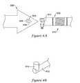
- FIG. 5Ais a side view of an illustrative electrode insertion tool and an illustrative lead in a detached configuration
- FIG. 5Bis an axial elevation view of the distal end of the illustrative electrode insertion tool of FIG. 5A ;
- FIG. 5Cis a side view of the illustrative electrode insertion tool and the illustrative lead of FIG. 5A in an attached configuration
- FIGS. 6A and 6Bare side views of an illustrative electrode insertion tool and an illustrative lead in detached and attached configurations;
- FIGS. 7A-7Bare cross-sectional views of an illustrative electrode insertion tool and an illustrative lead assembly in detached and attached configurations to illustrate a locking mechanism
- FIG. 7Cillustrates another locking mechanism
- FIG. 8Ais a side view of another illustrative electrode insertion tool and an illustrative lead in a detached configuration
- FIG. 8Bis a closer view of the distal tip of the illustrative lead in FIG. 8A ;
- FIGS. 8C-8Dare perspective views showing detached and attached configurations for the illustrative electrode insertion tool and illustrative lead of FIG. 8A .
- the proximal end of an electrode insertion toolis the end having a handle for grasping by the physician
- the distal end of an electrode insertion toolis the end having a dissecting tip for forming a path or opening through tissue and/or between layers of tissue.
- the proximal end of a lead electrode assemblyis the end that is connected to an associated canister, while other end of a lead electrode assembly is referred to as the distal end.
- FIG. 1is a perspective view of an illustrative electrode insertion tool set.
- the illustrative set 10includes several elements, including a straight introducer 12 having a handle 14 , a shaft 16 , and a distal tip 18 .
- a curved introducer 20is also shown, and includes a handle 22 , a shaft 24 , and a distal tip 26 .
- a shaping tool 30is also shown, the shaping tool having posts 32 disposed thereon. The shaping tool 30 may be used to adjust the curvature or shape of either of the introducers 12 , 20 .
- the handle of either or both introducers 12 , 20may include a port for fluid infusion, and the shafts 16 , 24 or distal tips 18 , 26 may include one or more ports allowing fluid (such as a local anesthetic, for example, lidocaine) to be infused during the insertion procedure.
- the distal tips 18 , 26may be shaped for blunt dissection including, for example, a relatively sharp distal tip portion forming a generally conical dissection element. This allows for piercing and/or separation of tissue to form a space for insertion of a lead electrode assembly.
- a straight electrode insertion toolhas an overall length, including the handle, of about 26.5 cm, with the shaft having an outer diameter of about 3.2 millimeters. Other embodiments may range from about 1 mm to about 6 mm in outer shaft diameter, with an overall length between about 10 cm and about 40 cm.
- An illustrative shaftis formed of stainless steel, with a polycarbonate proximal handle. Alternatively, a polymer providing added shapeability may be used for the shaft. A polytetrafluoroethylene coating may be used, if desired. Other coatings may be used, including drug eluting coatings.
- the overall sizemay be modified in light of patient anatomy, desired implant location, and the size of the lead electrode assembly being used, for example.
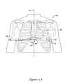
- FIGS. 2A-2Eshow steps of an illustrative method of implantation of a cardiac stimulus device and lead assembly to a subcutaneous location.
- a patient 40is shown having a heart generally at 42 , with the median or sagittal plane shown generally at 44 .
- a first incision 48is made at a medial location.
- the first incision 48is about 1 cm to about 2 cm inferior to the xiphoid process.
- a subcutaneous pocket 50may be formed in a suitable fashion for receiving the canister of the cardiac stimulus device, with the subcutaneous pocket 50 formed near a second incision 52 .
- An electrode insertion toolis shown, with shaft 54 and handle 56 , and, as indicated by the arrow, is inserted through the first incision 48 and advanced toward the second incision 52 , creating a channel through the patient's subcutaneous tissue.
- the insertion toolis advanced through first incision 48 toward the second incision 52 through subcutaneous tissue until the distal end 58 exits the second incision 52 , such that the shaft 54 temporarily resides in the subcutaneous tissue of the patient.
- a lead assembly 60is provided, with a distal end 62 and a proximal end 64 .
- the proximal end of the lead assembly 60is shown including a plug or connector for attachment to an associated canister.
- the distal end 62 of the lead assembly 60is secured to the distal end 58 of the electrode insertion tool.
- the physiciangrasps the handle 56 and, as indicated by the arrow, withdraws the electrode insertion tool via the first incision 48 , pulling the lead assembly 60 into the subcutaneous space or channel previously dissected.
- the lead assembly 60now resides partly in the patient's subcutaneous tissue, with the proximal end with plug or connector 64 sitting outside of the patient near the second incision 52 , and the distal end 62 extending out of first incision 48 .
- the next stepis for the insertion tool to be inserted through a third incision 70 and advanced toward and through the first incision 48 .
- the third incision 70may be approximately 8-10 cm (or more or less, depending on patient anatomy) above the first incision 48 , to the left of the median or sagittal plane 44 , and cephalad of the first incision 48 .
- the first and second incisionsmay be placed such that a line drawn therebetween is parallel to the patient's sternal midline, with the incisions being spaced about 0 cm to about 5 cm to the left of the sternal midline.
- a parasternal implant locationis achieved by placing the incisions about 3 cm to the left of the sternal midline.
- the insertion toolis advanced toward the first incision 48 until the distal end 58 of the insertion tool exits the first incision 48 .
- the lead assembly 60is manipulated such that its distal end 62 is adjacent the distal end 58 of the insertion tool.
- the distal end 62 of the lead assembly 60is then secured to the distal end 58 of the insertion tool.
- An implanting physicianthen grasps the handle 56 and withdraws the insertion tool as indicated by the arrow, pulling the distal end 62 of the lead assembly 60 toward the third incision 70 .
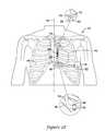
- FIG. 2Eillustrates the completed procedure.
- the lead assembly 60is disposed in a subcutaneous space in a generally “L” shape.
- the distal end 62 of the lead assembly 60is disposed near the third incision, which is shown as a closed incision 70 ′.
- the distal end 62 of the lead assembly 60may be secured, using suture hole 66 , to the fascia near the third incision by sutures 68 .
- a medial portion of the lead assembly 60may be secured to fascia near the first incision (shown as closed incision 48 ′) using suture(s) 86 that are secured to a suture sleeve 84 that may be secured to the lead assembly 60 .
- sutures 68 , 86are optional, but may aid in acute retention of the position of implantation. As time passes, tissue surrounding the electrode and/or lead assembly will fibrose and also hold the lead assembly in place.
- the sutures 68 , 86may formed of biocompatible, dissolvable material.
- FIG. 2Ealso illustrates placement of the canister 78 relative to the rest of the implanted system.
- the canister 78is placed near the second incision (shown at closed incision 52 ′) in the subcutaneous pocket 50 ( FIG. 2A ).
- the lead assembly 60is secured to the canister 78 , and extends first medially toward the first incision (shown as closed incision 48 ′) and then cephalad toward the third incision (shown at closed incision 70 ′).
- a distal portion of the lead assembly 60is shown as including a plurality of electrodes, as shown at 80 .
- the number and type of electrode(s)may vary, with at least one electrode included.
- the electrodes 80include a distal ring electrode used primarily for sensing, a proximal ring electrode also used primarily for sensing, and a coil electrode therebetween, with the coil electrode used for delivering stimulus, although each electrode may perform more than one function.
- the canister 78may also include one or more electrodes.
- the lead assembly 60further includes a proximally extending shaft having conductors passing therethrough, with the shaft providing insulation to the conductors, and with the conductor(s) coupled to the one or more electrodes.
- the first incision 48 and/or third incision 70may be at different locations, for example, to the right of the median or saggital plane, or, rather than at an anterior position as shown, posterior to the patient.
- the pocket 50 for receiving the canister of the systemmay be moved to a more cephalad position (for example, near the clavicle).
- the canister 78is shown as generally rectangular, although other shapes, including a long, narrow shape that conforms to the patient's ribcage, may instead be used.
- Part of the implantation procedure shown in FIGS. 2A-2Eincludes steps in which an electrode insertion tool is used to first create a subcutaneous pathway, is then connected at its distal end to a lead assembly, and is then used to pull the lead assembly through the just created subcutaneous pathway.
- these stepsmay be performed twice, such that either one electrode insertion tool is coupled to, de-coupled from, re-coupled to, and re-de-coupled from the lead assembly, or first and second electrode insertion tools are successively coupled to and decoupled from the lead assembly.
- the implantation procedure in FIGS. 2A-2Edoes not require the use of a splittable sheath. Additional structures, such as a sheath or a splittable sheath may be added, if desired, but the procedure does not require such elements.
- the methodthus includes establishing a subcutaneous pathway by the use of an implantation tool, securing a lead assembly for use in the cardiac device system to the implantation tool, and pulling the lead assembly into the subcutaneous pathway, wherein the lead assembly is pulled into the subcutaneous pathway in its finished condition, without the use of a sheath or splittable sheath thereon.
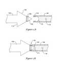
- FIG. 3Ais a side view of an illustrative electrode insertion tool 100 and an illustrative lead assembly 102 in a detached configuration.
- FIG. 3Agenerally shows the distal ends of each of the illustrative electrode insertion tool 100 and the illustrative lead assembly 102 .
- the electrode insertion tool 100includes a dissecting tip 104 , which is shown as a generally sharp member. Proximal and adjacent to the dissecting tip 104 is a lead engaging structure 106 that is configured for engaging the lead assembly 102 . Further proximal on the electrode insertion tool 100 is a dissecting portion 108 that is shaped to further expand and dissect subcutaneous space as the electrode insertion tool 100 is advanced through subcutaneous tissue.
- the lead assembly 102also includes an engagement structure 110 that is configured to engage and secure to the tool 100 .
- the engagement structures 106 , 110take the form of cooperating threading that allows for rotational fixation of the lead assembly 102 to the introducer 100 .
- the lead assembly 102defines, at its distal end, a cavity wall 112 shaped to receive the dissecting tip 104 therein.
- the lead assembly 102includes a receiving structure including both the engagement structure 110 and the cavity/cavity wall 112 .
- a suture hole 116which may be used, as illustrated in FIG. 2E , to provide an acute or chronic retention structure.
- the electrode insertion tool 100is shown as including a proximally facing shoulder 114 .
- This shoulder 114may be abrupt, as shown, or may be smoothed or curved in to avoid catching on and/or tearing subcutaneous tissue as the electrode insertion tool 100 is manipulated in a proximal direction.
- the outer diameter of the dissecting portion 108 and/or proximally facing shoulder 114may be sized to be greater than the outer diameter of the lead assembly 102 such that, as the lead assembly 102 is pulled through subcutaneous tissue, drag on the lead assembly 102 is reduced to avoid damage during the pulling step.
- the outer diameter of the dissecting portion 108may be about 0.3 mm to about 5.0 mm larger than the outer diameter of a corresponding lead assembly 102 to reduce drag.
- the outer diameter for the electrode insertion tool 100is generally similar to the outer diameter of the lead assembly 102 , which may reduce the level of patient discomfort during the procedure.
- FIG. 3Bis a side view of the electrode insertion tool and the lead of FIG. 3A in an attached configuration.
- the electrode insertion tool 100is secured to the lead assembly 102 , with the cooperative threading of the engaging structures removably fixing the two pieces 100 , 102 together.
- the cavity wall 112is formed such that the dissecting tip 104 is easily received in the distal end of the lead assembly 102 while the electrode insertion tool 100 is attached to the lead assembly 102 .
- the suture hole 116may be used to secure the lead assembly in place.
- the direct attachment of the lead assembly 102 to the electrode insertion tool 100allows for a simple and quick implantation procedure.
- FIG. 4Ais a longitudinal cross-sectional view of another illustrative electrode insertion tool 200 and an illustrative lead assembly 202 in a detached configuration.
- the electrode insertion tool 200includes a dissecting tip 204 , an engaging structure 206 , and a dissecting portion 208 .
- the dissecting tip 204may be sharp or blunt, and the dissecting portion 208 is sized to further expand a subcutaneous channel formed as the electrode insertion tool 200 is advanced through tissue.
- an internal channel 210is also illustrated.
- the internal channel 210may be used to infuse a fluid during the implantation procedure, for example, a local anesthetic, anti-inflammatory drugs, antibiotics, visualization media or any other suitable material, as desired.
- the channel 210is shown with openings at various locations, including on the dissecting portion 208 as well as the more proximal shaft region of the electrode insertion tool 200 . These openings may be placed as desired. In addition, an opening may be placed at or near the dissecting tip 204 .
- FIG. 4Aalso illustrates the illustrative lead assembly 202 as including an engaging structure 212 , which generally includes a ridge 214 , and a cavity 216 .
- the cavity 216 and engaging structure 212provide a receiving location for a distal portion of the electrode insertion tool 200 such that the ridge 214 secures the lead to the tool 200 .
- the lead assembly 202may also include a suture hole as shown at 218 .
- FIGS. 4C , 4 D and 4 Eillustrate various forms for the engaging structures, and are further explained below. These structures may include select twist-locking structures and/or a slide-over or snap-fit structure, as further explained below.
- FIG. 4Bis a longitudinal cross-sectional view of the electrode insertion tool and the illustrative lead of FIG. 4A in an attached configuration.
- the dissecting tip 204 of the electrode insertion tool 200is disposed in the cavity 216 of the lead assembly 202 , with the tool engaging structure 212 of the lead assembly coupled to the lead engaging structure 206 of the electrode insertion tool 200 .
- FIGS. 4C-4Eare elevation views of constructions along lines C-C, D-D and E-E of the illustrative electrode insertion tool 200 and illustrative lead assembly 202 of FIG. 4A .
- the electrode insertion tool 200is shown as including the dissecting tip 204 , lead engaging structure 206 , and dissecting portion 208 .
- the lead engaging structure 206is shown generally at 230 as including a pair of tabs.
- the lead assembly 202is shown as including a ridge 214 about cavity 216 .
- the ridge 214is shown generally as a disc that extends inward from an outer sheath into the chamber 216 , the disc including a pair of gaps 232 that are spaced and sized to receive the tabs 230 of the lead engaging structure 206 .
- FIG. 4Fit can be seen that the disc provides a ledge 234 for holding tabs 230 .
- the tool engaging structureis shown in FIG. 4F as including a ramp 236 that leads up to a slot 238 .
- the illustrative electrode insertion tool 200includes an engaging structure 206 ′ including an annular disc 240 .
- the annular disc 240projects out from the surface of the engaging structure, but with a lesser diameter than the outer diameter of the dissecting portion 208 .
- the lead assembly 202includes a chamber 216 and a ridge 214 ′ which is also a disc 242 structure, this time projecting inward from the outer wall of the chamber 216 .
- One, the other, or both of the discs 240 , 242may be flexible to allow the discs to be passed over one another.
- FIG. 4Eanother construction is shown, this time with the electrode insertion tool 200 including an engagement structure 206 ′′ having a disc defining gaps 250 .
- the engagement structure 206 ′′sits proximal of the dissecting tip 204 and distal of the dissecting portion 208 .
- the lead assembly 202includes a ridge 214 ′′ and a chamber 216 , with the ridge 214 ′′ reduced to tabs 252 sized to fit through the gaps 250 of the electrode insertion tool 200 .
- FIG. 4Gshows the structure of the electrode insertion tool from line G-G.
- the engaging structure 206 ′′ on the electrode insertion tool 200again includes the gap 250 and defines a channel for sliding the tabs 252 up a ramp 254 to a receiving slot 256 . Again, a certain amount of axial tension may help to retain the tab(s) 252 in the slot 256 .
- the number and shape of the tabs 230 , 252may vary, and the particulars described in each structure are merely illustrative of some embodiments.
- FIG. 5Ais a side view of an illustrative electrode insertion tool 300 and an illustrative lead assembly 302 in a detached configuration.
- the electrode insertion tool 300again includes a dissecting tip 304 , an engaging structure 306 , and a dissecting portion 308 which may be included to further dissect tissue.
- the engaging structureincludes a slot 310 that is adapted to receive a corresponding engaging structure 320 on the lead assembly 302 . Openings 312 are also shown and communicate with the slot 310 , allowing a suture to pass therethrough.
- the lead assembly 302includes, as indicated, an engaging structure 320 , which is shown as including a suture hole.
- the lead assembly 302may include any suitable number, configuration, and type of electrodes.
- One suitable configurationis shown in FIG. 5A as including a distal ring electrode 322 and a proximal ring electrode 326 , with a coil electrode 324 therebetween. Other configurations may also be used, as suits the particular system, application, and patient.
- the lead assembly 302includes an engaging structure 320 that extends therefrom.
- the engaging structure 320 of the lead assembly 302is sized and shaped for placement in the slot 310 of the electrode insertion tool 300 .
- the engaging structure 320 of the lead assembly 302is shown with a suture hole that may be used both in securing the lead assembly to the electrode insertion tool, and also for suturing to tissue after placement.
- FIG. 5Bis an axial elevation view of the distal end of the illustrative electrode insertion tool of FIG. 5A .
- the electrode insertion tool 300includes the dissecting tip 304 and the engaging structure 306 .
- the dissecting portion 308is omitted, as it may be omitted in some embodiments not only of the electrode insertion tool 300 in FIGS. 5A-5C , but also in the other embodiments shown herein.
- the engaging structure 306includes slot 310 and openings 312 that communicate with the slot 310 .
- FIG. 5Cis a side view of the illustrative electrode insertion tool and the illustrative lead of FIG. 5A in an attached configuration.
- the engaging structure 320 of the lead assembly 302is inserted into the slot 310 .
- a suture 330passes through the openings 312 to the suture hole on the engaging structure 320 of the lead assembly 302 while it rests in the slot 310 .
- the suture 330secures the lead assembly 302 to the electrode insertion tool 300 .
- the engaging structure 320 of the lead assembly 302may be shaped or marked to aid in correct alignment of the suture hole of the engaging structure 320 with the openings 312 and the slot 310 .
- the engaging structure 320 of the lead assemblymay be oblong or polygonal.
- the electrode insertion tool 300includes a receiving portion for receiving the engaging structure 320 of the lead assembly 302 .
- the receiving portionincludes the engaging structure 306 at the distal end of the electrode insertion tool.
- FIG. 6Ais a side view of an illustrative electrode insertion tool 400 and an illustrative lead assembly 402 in a detached configuration.
- the electrode insertion tool 400includes a dissecting tip 404 , an engaging structure 406 and a dissecting portion 416 .
- the example lead assembly 402includes an engaging structure 420 including a suture hole 422 , as well as a configuration of multiple electrodes 424 , 426 , 428 .
- the illustrative engaging structure 406includes a hook 408 , elongate shaft 410 , and actuator 412 , with the actuator 412 shown as being associated with the device handle 414 .
- the hook 408is shown in a retracted position such that its distal end exits and then reenters the lead assembly 402 .
- the actuator 412is coupled to the elongate shaft 410 to control whether the hook 408 is in the retracted position shown in FIG. 6A or the extended position shown in FIG. 6B .
- FIG. 6Bis a side view of the illustrative electrode insertion tool and the illustrative lead of FIG. 6A in an attached configuration.
- the actuator 412 on the device handle 414has been manipulated, such that the hook 408 extends from the distal end of the electrode insertion tool 400 and away from the reentry opening 418 .
- the hook 408has been placed into the suture hole 422 on the engaging structure 420 of the lead assembly 402 .
- the engaging structure 406 of the electrode insertion tool 400interacts with the engaging structure 420 of the lead assembly 402 to secure the two together.
- a slotmay be provided on the electrode insertion tool 400 to receive the engaging structure 420 of the lead assembly as well, for example, in a manner as shown in FIGS. 5A-5C .
- FIGS. 7A-7Cshow an illustrative embodiment in which a locking structure is provided in addition to the engaging structures.
- an electrode insertion tool 500is shown detached from an illustrative lead assembly 502 .
- the electrode insertion tool 500includes a dissecting tip 504 , and engaging structure 506 (shown as threading), and a dissecting portion 508 .
- a locking structure 510is also shown.
- the lead assembly 502includes an engaging structure 512 for threading onto the engaging structure 506 of the electrode insertion tool 500 .
- the receiving chamber 514is configured to receive the distal end of the electrode insertion tool 500 .
- a locking structure 516is also shown, and is further explained by reference to FIG. 7B .
- the engaging structures 506 , 512 of the electrode insertion tool 500 and lead assembly 502are shown in a secured configuration.
- the locking structure 510 of the electrode insertion tool 500is shown as including a locking key 520 .
- the locking key 520engages the locking structure 516 of the lead assembly 502 , preventing the lead assembly 502 from becoming unthreaded from the electrode insertion tool 500 .
- FIG. 7Cshows another embodiment, including the actuator 542 for the locking key 520 .
- the actuator 542may be part of the device handle 540 .
- the locking key 520may be coupled to the actuator 542 by an elongate shaft extending through the length of the electrode insertion tool 500 .
- the embodiment of FIG. 7Cshows an alternative to the locking structure 516 of FIGS. 7A-7B .
- the lead assembly 502 ′may include a fin 532 that prevents full rotation of the lead assembly 502 ′ relative to the electrode insertion tool 500 when the locking key 520 is disposed in the receiving chamber 530 .
- Several fins 532may be provided, or a solid member may be provided to take up a portion of the space in the receiving chamber 530 to prevent rotation of the lead assembly 502 ′ relative to the electrode insertion tool 500 .
- FIGS. 7A-7Calso illustrate an electrode insertion tool 500 which includes a distal enlargement for dissecting patient tissue that has a distally facing dissecting portion 508 as well as a proximally facing, non-abrupt shoulder 550 .
- the proximally facing shoulder 550may be formed to allow smooth passage through the already dissected subcutaneous tissue, while also creating a pathway for drawing the lead assembly 502 , 502 ′ easily therethrough.
- a smooth shouldermay be provided in any suitable fashion, for example, by smoothing the outer edge of the shoulder down, or by providing an angled shoulder, as is shown in FIGS. 7A-7C .
- FIG. 8Ais a side view of another illustrative electrode insertion tool 600 and an illustrative lead assembly 602 in a detached configuration.
- the electrode insertion tool 600includes a receiving portion 604 located proximal of a dissecting tip, with an additional dissecting portion extending proximally of the receiving portion 604 .
- the receiving portion 604includes a channel 606 and a slot 608 , with the channel 606 and the slot 608 shown in phantom to illustrate that they are not open to the outer surface of the electrode insertion tool 600 .
- the illustrative lead assembly 602includes electrodes 610 and an attachment structure 612 including a tab 614 .
- FIG. 8Bis a closer view of the distal tip of the illustrative lead in FIG. 8A .
- the attachment structure 612extends axially from the distal end of the lead assembly 602 ( FIG. 8A ).
- a tab 614extends laterally from the distal end of the attachment structure 612 .
- the attachment structure 612 and tab 614are configured to cooperate with the receiving portion 604 , channel 606 and slot 608 shown in FIG. 8A , as is further shown in FIGS. 8C-8D .
- FIGS. 8C-8Dare perspective views showing detached and attached configurations for the illustrative electrode insertion tool and illustrative lead of FIG. 8A .
- the attachment structure 612is aligned such that the tab 614 aligns with the receiving portion 604 .
- the attachment structure 612is inserted in the receiving portion 604 until the tab 614 is inside the receiving portion and aligns with the channel 606 .
- the attachment structure 612 and lead assemblyare then rotated relative to the insertion tool 600 (or vice versa), such that the tab 614 slides through the channel 632 .
- the slot 608is included.
- the slot 608is optional, and may be omitted if desired.
- the lead assembly and insertion tool 600are moved axially relative to one another such that the tab 614 enters the (optional) slot 608 .
- FIG. 8Dshows the lead assembly secured to the insertion tool 600 , with the attachment structure 812 engaged with the slot 608 after passing the tab 614 through the receiving portion 604 and channel 606 . While in this configuration, the insertion tool 600 is drawn out through the subcutaneous path it established prior to being connected to the lead assembly. Once the insertion tool 600 has been withdrawn, the engaging structure 612 is disengaged by maneuvering the tab 614 out of the slot 608 , into the channel 606 , and around to the receiving structure 604 .
Landscapes
- Health & Medical Sciences (AREA)
- Heart & Thoracic Surgery (AREA)
- Cardiology (AREA)
- Engineering & Computer Science (AREA)
- Biomedical Technology (AREA)
- Nuclear Medicine, Radiotherapy & Molecular Imaging (AREA)
- Radiology & Medical Imaging (AREA)
- Life Sciences & Earth Sciences (AREA)
- Animal Behavior & Ethology (AREA)
- General Health & Medical Sciences (AREA)
- Public Health (AREA)
- Veterinary Medicine (AREA)
- Electrotherapy Devices (AREA)
Abstract
Description
The present application is related to that of U.S. patent application Ser. No. 11/006,291, titled APPARATUS AND METHOD FOR SUBCUTANEOUS ELECTRODE INSERTION, published as US 2006-0122676 A1 on Jun. 8, 2006 and now U.S. Pat. No. 7,655,014, which is incorporated herein by reference.
The present invention relates to the field of implantable cardiac stimulus device systems. More specifically, the present invention relates to insertion tools, lead assemblies, methods and kits for placement of cardiac device electrodes.
Implantable cardiac stimulus and/or monitoring devices and systems are known for use in ongoing and prophylactic treatment of cardiac conditions as well as diagnosis of cardiac maladies. Often such systems will include one or more lead assemblies that carry electrodes that may be used to sense cardiac activity and/or to deliver therapy to the patient. Convenient and uncomplicated, as well as quick, implantation of the lead assemblies is desirable, and alternatives to existing technologies and methods are sought.
The present invention is, in several embodiments, directed toward insertion tools, lead assemblies, kits, and methods for placement of cardiac device electrodes. In some embodiments, an insertion tool having a proximal end and a distal, dissecting end includes a structure configured to receive or engage a structure on a lead assembly. Some embodiments include a lead assembly having an end including a structure configured for engaging the distal end of an associated insertion tool. Some embodiments include kits or systems including both an insertion tool and a lead assembly, each having a structure for engaging the other. In these embodiments, the engaging structures may take several forms including threads, small posts, circular or semi-circular receiving members, and/or a slot. Some embodiments also include methods for placement of cardiac device electrodes with the assistance of an associated insertion tool, wherein the cardiac device electrodes are associated with a lead assembly having an end configured to engage a distal, dissecting portion of an associated insertion tool.
The following detailed description should be read with reference to the drawings. The drawings, which are not necessarily to scale, depict illustrative embodiments and are not intended to limit the scope of the invention.
As used herein, the proximal end of an electrode insertion tool is the end having a handle for grasping by the physician, and the distal end of an electrode insertion tool is the end having a dissecting tip for forming a path or opening through tissue and/or between layers of tissue. The proximal end of a lead electrode assembly is the end that is connected to an associated canister, while other end of a lead electrode assembly is referred to as the distal end.
In an illustrative embodiment, a straight electrode insertion tool has an overall length, including the handle, of about 26.5 cm, with the shaft having an outer diameter of about 3.2 millimeters. Other embodiments may range from about 1 mm to about 6 mm in outer shaft diameter, with an overall length between about 10 cm and about 40 cm. An illustrative shaft is formed of stainless steel, with a polycarbonate proximal handle. Alternatively, a polymer providing added shapeability may be used for the shaft. A polytetrafluoroethylene coating may be used, if desired. Other coatings may be used, including drug eluting coatings. The overall size may be modified in light of patient anatomy, desired implant location, and the size of the lead electrode assembly being used, for example.
Turning toFIG. 2B , the insertion tool is advanced throughfirst incision 48 toward thesecond incision 52 through subcutaneous tissue until thedistal end 58 exits thesecond incision 52, such that theshaft 54 temporarily resides in the subcutaneous tissue of the patient. Next, alead assembly 60 is provided, with adistal end 62 and aproximal end 64. The proximal end of thelead assembly 60 is shown including a plug or connector for attachment to an associated canister. Thedistal end 62 of thelead assembly 60 is secured to thedistal end 58 of the electrode insertion tool. The physician then grasps thehandle 56 and, as indicated by the arrow, withdraws the electrode insertion tool via thefirst incision 48, pulling thelead assembly 60 into the subcutaneous space or channel previously dissected.
Referring now toFIG. 2C , the result of the steps shown inFIG. 2B is that thelead assembly 60 now resides partly in the patient's subcutaneous tissue, with the proximal end with plug orconnector 64 sitting outside of the patient near thesecond incision 52, and thedistal end 62 extending out offirst incision 48. As indicated inFIG. 2C , the next step is for the insertion tool to be inserted through athird incision 70 and advanced toward and through thefirst incision 48. Thethird incision 70 may be approximately 8-10 cm (or more or less, depending on patient anatomy) above thefirst incision 48, to the left of the median orsagittal plane 44, and cephalad of thefirst incision 48. The first and second incisions may be placed such that a line drawn therebetween is parallel to the patient's sternal midline, with the incisions being spaced about 0 cm to about 5 cm to the left of the sternal midline. In the embodiment shown, a parasternal implant location is achieved by placing the incisions about 3 cm to the left of the sternal midline. The insertion tool is advanced toward thefirst incision 48 until thedistal end 58 of the insertion tool exits thefirst incision 48.
Turning toFIG. 2D , thelead assembly 60 is manipulated such that itsdistal end 62 is adjacent thedistal end 58 of the insertion tool. Thedistal end 62 of thelead assembly 60 is then secured to thedistal end 58 of the insertion tool. An implanting physician then grasps thehandle 56 and withdraws the insertion tool as indicated by the arrow, pulling thedistal end 62 of thelead assembly 60 toward thethird incision 70.
A distal portion of thelead assembly 60 is shown as including a plurality of electrodes, as shown at80. The number and type of electrode(s) may vary, with at least one electrode included. In an illustrative embodiment, the electrodes80 include a distal ring electrode used primarily for sensing, a proximal ring electrode also used primarily for sensing, and a coil electrode therebetween, with the coil electrode used for delivering stimulus, although each electrode may perform more than one function. Thecanister 78 may also include one or more electrodes. Thelead assembly 60 further includes a proximally extending shaft having conductors passing therethrough, with the shaft providing insulation to the conductors, and with the conductor(s) coupled to the one or more electrodes.
Alternatives to the steps shown inFIGS. 2A-2E are available in other embodiments. In some embodiments, thefirst incision 48 and/orthird incision 70 may be at different locations, for example, to the right of the median or saggital plane, or, rather than at an anterior position as shown, posterior to the patient. Further, thepocket 50 for receiving the canister of the system may be moved to a more cephalad position (for example, near the clavicle). Thecanister 78 is shown as generally rectangular, although other shapes, including a long, narrow shape that conforms to the patient's ribcage, may instead be used.
Part of the implantation procedure shown inFIGS. 2A-2E includes steps in which an electrode insertion tool is used to first create a subcutaneous pathway, is then connected at its distal end to a lead assembly, and is then used to pull the lead assembly through the just created subcutaneous pathway. When the desired configuration has an “L” shape as shown byFIG. 2E , these steps may be performed twice, such that either one electrode insertion tool is coupled to, de-coupled from, re-coupled to, and re-de-coupled from the lead assembly, or first and second electrode insertion tools are successively coupled to and decoupled from the lead assembly. In either event, it is desired to have the ability to readily and easily couple the lead assembly to the electrode insertion tool to perform the step of pulling the lead assembly through the patient's subcutaneous tissue to a desired location. Following are several illustrative examples that provide such functionality.
It may also be noted that the implantation procedure inFIGS. 2A-2E does not require the use of a splittable sheath. Additional structures, such as a sheath or a splittable sheath may be added, if desired, but the procedure does not require such elements. The method thus includes establishing a subcutaneous pathway by the use of an implantation tool, securing a lead assembly for use in the cardiac device system to the implantation tool, and pulling the lead assembly into the subcutaneous pathway, wherein the lead assembly is pulled into the subcutaneous pathway in its finished condition, without the use of a sheath or splittable sheath thereon.
Thelead assembly 102 also includes anengagement structure 110 that is configured to engage and secure to thetool 100. In the illustrative embodiment, theengagement structures lead assembly 102 to theintroducer 100. Thelead assembly 102 defines, at its distal end, acavity wall 112 shaped to receive the dissectingtip 104 therein. As such, thelead assembly 102 includes a receiving structure including both theengagement structure 110 and the cavity/cavity wall 112. Also shown on thelead assembly 102 is asuture hole 116, which may be used, as illustrated inFIG. 2E , to provide an acute or chronic retention structure.
Theelectrode insertion tool 100 is shown as including aproximally facing shoulder 114. Thisshoulder 114 may be abrupt, as shown, or may be smoothed or curved in to avoid catching on and/or tearing subcutaneous tissue as theelectrode insertion tool 100 is manipulated in a proximal direction. The outer diameter of the dissectingportion 108 and/or proximally facingshoulder 114, in some embodiments, may be sized to be greater than the outer diameter of thelead assembly 102 such that, as thelead assembly 102 is pulled through subcutaneous tissue, drag on thelead assembly 102 is reduced to avoid damage during the pulling step. For example, the outer diameter of the dissectingportion 108 may be about 0.3 mm to about 5.0 mm larger than the outer diameter of a correspondinglead assembly 102 to reduce drag. In other embodiments, the outer diameter for theelectrode insertion tool 100 is generally similar to the outer diameter of thelead assembly 102, which may reduce the level of patient discomfort during the procedure.
In the embodiment ofFIG. 4A , aninternal channel 210 is also illustrated. Theinternal channel 210 may be used to infuse a fluid during the implantation procedure, for example, a local anesthetic, anti-inflammatory drugs, antibiotics, visualization media or any other suitable material, as desired. Thechannel 210 is shown with openings at various locations, including on the dissectingportion 208 as well as the more proximal shaft region of theelectrode insertion tool 200. These openings may be placed as desired. In addition, an opening may be placed at or near the dissectingtip 204.
The embodiment ofFIG. 4A also illustrates theillustrative lead assembly 202 as including an engagingstructure 212, which generally includes aridge 214, and acavity 216. Thecavity 216 andengaging structure 212 provide a receiving location for a distal portion of theelectrode insertion tool 200 such that theridge 214 secures the lead to thetool 200. Thelead assembly 202 may also include a suture hole as shown at218. As indicated by the alternate view lines,FIGS. 4C ,4D and4E illustrate various forms for the engaging structures, and are further explained below. These structures may include select twist-locking structures and/or a slide-over or snap-fit structure, as further explained below.
Referring now toFIG. 4D , a slide-over or snap-fit structure is illustrated. In particular, the illustrativeelectrode insertion tool 200 includes an engagingstructure 206′ including anannular disc 240. Theannular disc 240 projects out from the surface of the engaging structure, but with a lesser diameter than the outer diameter of the dissectingportion 208. Thelead assembly 202 includes achamber 216 and aridge 214′ which is also adisc 242 structure, this time projecting inward from the outer wall of thechamber 216. One, the other, or both of thediscs
Referring now toFIG. 4E , another construction is shown, this time with theelectrode insertion tool 200 including anengagement structure 206″ having adisc defining gaps 250. Again, theengagement structure 206″ sits proximal of the dissectingtip 204 and distal of the dissectingportion 208. Thelead assembly 202 includes aridge 214″ and achamber 216, with theridge 214″ reduced totabs 252 sized to fit through thegaps 250 of theelectrode insertion tool 200.FIG. 4G shows the structure of the electrode insertion tool from line G-G. As can be seen, the engagingstructure 206″ on theelectrode insertion tool 200 again includes thegap 250 and defines a channel for sliding thetabs 252 up aramp 254 to a receivingslot 256. Again, a certain amount of axial tension may help to retain the tab(s)252 in theslot 256.
InFIGS. 4C and 4E , the number and shape of thetabs
Thelead assembly 302 includes, as indicated, an engagingstructure 320, which is shown as including a suture hole. Thelead assembly 302, as with each lead assembly shown herein, may include any suitable number, configuration, and type of electrodes. One suitable configuration is shown inFIG. 5A as including adistal ring electrode 322 and aproximal ring electrode 326, with acoil electrode 324 therebetween. Other configurations may also be used, as suits the particular system, application, and patient. Thelead assembly 302 includes an engagingstructure 320 that extends therefrom. As explained below by reference toFIG. 5C , the engagingstructure 320 of thelead assembly 302 is sized and shaped for placement in theslot 310 of theelectrode insertion tool 300. Also, the engagingstructure 320 of thelead assembly 302 is shown with a suture hole that may be used both in securing the lead assembly to the electrode insertion tool, and also for suturing to tissue after placement.
In the embodiment ofFIGS. 5A-5C , theelectrode insertion tool 300 includes a receiving portion for receiving the engagingstructure 320 of thelead assembly 302. The receiving portion includes the engagingstructure 306 at the distal end of the electrode insertion tool.
The illustrativeengaging structure 406 includes ahook 408,elongate shaft 410, andactuator 412, with theactuator 412 shown as being associated with thedevice handle 414. Thehook 408 is shown in a retracted position such that its distal end exits and then reenters thelead assembly 402. Theactuator 412 is coupled to theelongate shaft 410 to control whether thehook 408 is in the retracted position shown inFIG. 6A or the extended position shown inFIG. 6B .
Thelead assembly 502 includes an engagingstructure 512 for threading onto the engagingstructure 506 of theelectrode insertion tool 500. The receivingchamber 514 is configured to receive the distal end of theelectrode insertion tool 500. A lockingstructure 516 is also shown, and is further explained by reference toFIG. 7B .
Referring toFIG. 7B , the engagingstructures electrode insertion tool 500 andlead assembly 502 are shown in a secured configuration. The lockingstructure 510 of theelectrode insertion tool 500 is shown as including a lockingkey 520. When advanced as shown, the lockingkey 520 engages the lockingstructure 516 of thelead assembly 502, preventing thelead assembly 502 from becoming unthreaded from theelectrode insertion tool 500.
In the illustrative embodiment ofFIGS. 8A-8D , theslot 608 is included. Theslot 608 is optional, and may be omitted if desired. As indicated byline 634, once thetab 614 slides through thechannel 606 to a position in alignment with theslot 608, the lead assembly andinsertion tool 600 are moved axially relative to one another such that thetab 614 enters the (optional)slot 608.
Those skilled in the art will recognize that the present invention may be manifested in a variety of forms other than the specific embodiments described and contemplated herein. Accordingly, departures in form and detail may be made without departing from the scope and spirit of the present invention as described in the appended claims.
Claims (9)
1. A system for implanting an implantable cardiac stimulus device having an implantable canister, the system comprising:
an introducer tool for implanting a lead for the implantable cardiac stimulus device, the introducer tool having a proximal end with a handle, a distal end including a dissecting tip, and a shaft therebetween, the distal end also including an engaging structure disposed on an outer portion of the shaft at a location proximal of but adjacent to the dissecting tip; and
a cardiac electrode lead having at least one of a sensing electrode and/or a stimulus electrode disposed thereon, the lead comprising a first end having a receiving structure configured to receive the dissecting tip therein and engage the engaging structure of said introducer tool, and a second end having an attachment structure for attaching to the implantable canister; wherein:
the engaging structure and the first end of the lead are configured for releasable coupling to one another;
the engaging structure includes a threaded portion;
the receiving structure includes threads for matching the engaging structure; and
the threaded portion of the engaging structure forms part of an outer surface of the dissecting tip of the introducer tool.
2. The system ofclaim 1 , wherein the receiving structure and the engaging structure are configured for twisting engagement thereof.
3. The system ofclaim 1 , wherein the introducer tool further comprises means for locking the introducer tool and the cardiac electrode lead in an engaged state.
4. The system ofclaim 1 wherein the dissecting tip further comprises a dissecting portion proximal to the engaging structure, the dissecting portion shaped to further separate subcutaneous tissue relative to the dissecting tip such that, when the engaging structure is used to secure the lead thereto, and the handle is pulled in a proximal direction, the dissecting portion reduces drag on the lead.
5. The system ofclaim 4 , wherein the dissecting tip, engaging structure, and dissecting portion of the tool generally form a conical portion with a discontinuity at the engaging structure, the discontinuity extending at least partly about the conical portion.
6. The system ofclaim 5 , wherein the discontinuity extends wholly around the conical portion.
7. The system ofclaim 1 , wherein the tool further comprises means for locking the tool to the lead when engaged therewith, and the lead further comprises corresponding means for locking the lead to the tool when engaged therewith.
8. The system ofclaim 1 wherein the tool further comprises a locking member coupled to a control mechanism disposed relative to the handle, the locking member configured to lock the tool in an engaged position in response to actuation by the control mechanism.
9. The system ofclaim 1 wherein the tool further includes a shoulder adjacent and proximal to the dissecting tip, wherein the shoulder is shaped for non-traumatic passage in a proximal direction through subcutaneous tissue such that atraumatic passage of the lead occurs when the tool is withdrawn through tissue while engaged with the lead at the engaging structure of the tool.
Priority Applications (2)
| Application Number | Priority Date | Filing Date | Title |
|---|---|---|---|
| US11/497,203US8718793B2 (en) | 2006-08-01 | 2006-08-01 | Electrode insertion tools, lead assemblies, kits and methods for placement of cardiac device electrodes |
| US14/218,267US9216284B2 (en) | 2006-08-01 | 2014-03-18 | Electrode insertion tools, lead assemblies, kits and methods for placement of cardiac device electrodes |
Applications Claiming Priority (1)
| Application Number | Priority Date | Filing Date | Title |
|---|---|---|---|
| US11/497,203US8718793B2 (en) | 2006-08-01 | 2006-08-01 | Electrode insertion tools, lead assemblies, kits and methods for placement of cardiac device electrodes |
Related Child Applications (1)
| Application Number | Title | Priority Date | Filing Date |
|---|---|---|---|
| US14/218,267DivisionUS9216284B2 (en) | 2006-08-01 | 2014-03-18 | Electrode insertion tools, lead assemblies, kits and methods for placement of cardiac device electrodes |
Publications (2)
| Publication Number | Publication Date |
|---|---|
| US20080046056A1 US20080046056A1 (en) | 2008-02-21 |
| US8718793B2true US8718793B2 (en) | 2014-05-06 |
Family
ID=39102381
Family Applications (2)
| Application Number | Title | Priority Date | Filing Date |
|---|---|---|---|
| US11/497,203Active2029-12-19US8718793B2 (en) | 2006-08-01 | 2006-08-01 | Electrode insertion tools, lead assemblies, kits and methods for placement of cardiac device electrodes |
| US14/218,267Active2026-08-12US9216284B2 (en) | 2006-08-01 | 2014-03-18 | Electrode insertion tools, lead assemblies, kits and methods for placement of cardiac device electrodes |
Family Applications After (1)
| Application Number | Title | Priority Date | Filing Date |
|---|---|---|---|
| US14/218,267Active2026-08-12US9216284B2 (en) | 2006-08-01 | 2014-03-18 | Electrode insertion tools, lead assemblies, kits and methods for placement of cardiac device electrodes |
Country Status (1)
| Country | Link |
|---|---|
| US (2) | US8718793B2 (en) |
Cited By (16)
| Publication number | Priority date | Publication date | Assignee | Title |
|---|---|---|---|---|
| US9168380B1 (en)* | 2014-07-24 | 2015-10-27 | Medtronic, Inc. | System and method for triggered pacing |
| US9357969B2 (en) | 2006-05-26 | 2016-06-07 | Cameron Health, Inc. | Sensing vector selection in a cardiac stimulus device with postural assessment |
| US9492671B2 (en) | 2014-05-06 | 2016-11-15 | Medtronic, Inc. | Acoustically triggered therapy delivery |
| US9669224B2 (en) | 2014-05-06 | 2017-06-06 | Medtronic, Inc. | Triggered pacing system |
| WO2017192870A1 (en) | 2016-05-04 | 2017-11-09 | Cardiac Pacemakers, Inc. | Electrode designs in implantable defibrillator systems |
| US10105187B2 (en) | 2015-08-27 | 2018-10-23 | Medtronic, Inc. | Systems, apparatus, methods and computer-readable storage media facilitating surgical procedures utilizing augmented reality |
| US10154794B2 (en) | 2014-04-25 | 2018-12-18 | Medtronic, Inc. | Implantable cardioverter-defibrillator (ICD) tachyarrhythmia detection modifications responsive to detected pacing |
| WO2019036571A1 (en) | 2017-08-17 | 2019-02-21 | Cardiac Pacemakers, Inc. | Single incision subcutaneous implantable defibrillation system |
| US10226197B2 (en) | 2014-04-25 | 2019-03-12 | Medtronic, Inc. | Pace pulse detector for an implantable medical device |
| US10448855B2 (en) | 2014-04-25 | 2019-10-22 | Medtronic, Inc. | Implantable medical device (IMD) sensing modifications responsive to detected pacing pulses |
| US10617402B2 (en) | 2015-07-22 | 2020-04-14 | Cameron Health, Inc. | Minimally invasive method to implant a subcutaneous electrode |
| US10751526B2 (en) | 2017-10-25 | 2020-08-25 | Cardiac Pacemakers, Inc. | Subcutaneous lead implantation |
| US10786679B2 (en) | 2016-12-21 | 2020-09-29 | Cardiac Pacemakers, Inc. | Lead with integrated electrodes |
| US10980570B2 (en) | 2017-01-12 | 2021-04-20 | Cardiac Pacemakers, Inc. | Implantation of an active medical device using the internal thoracic vasculature |
| US20210316135A1 (en)* | 2018-08-15 | 2021-10-14 | Cvrx, Inc. | Devices and methods for percutaneous electrode implant |
| US11235145B2 (en) | 2016-11-17 | 2022-02-01 | Cardiac Pacemakers, Inc. | Directional subcutaneous implantable cardioverter defibrillator electrode |
Families Citing this family (33)
| Publication number | Priority date | Publication date | Assignee | Title |
|---|---|---|---|---|
| US8718793B2 (en)* | 2006-08-01 | 2014-05-06 | Cameron Health, Inc. | Electrode insertion tools, lead assemblies, kits and methods for placement of cardiac device electrodes |
| US9008782B2 (en)* | 2007-10-26 | 2015-04-14 | Medtronic, Inc. | Occipital nerve stimulation |
| US20100030227A1 (en)* | 2008-07-31 | 2010-02-04 | Medtronic, Inc. | Medical lead implantation |
| WO2010068933A1 (en) | 2008-12-12 | 2010-06-17 | Cameron Health, Inc. | Electrode spacing in a subcutaneous implantable cardiac stimulus device |
| US9974944B2 (en)* | 2010-07-29 | 2018-05-22 | Cameron Health, Inc. | Subcutaneous leads and methods of implant and explant |
| US9326821B2 (en)* | 2011-04-29 | 2016-05-03 | Medtronic, Inc. | Medical tunneling device and method |
| US10933230B2 (en) | 2013-05-06 | 2021-03-02 | Medtronic, Inc. | Systems and methods for implanting a medical electrical lead |
| US20140330287A1 (en) | 2013-05-06 | 2014-11-06 | Medtronic, Inc. | Devices and techniques for anchoring an implantable medical device |
| US10556117B2 (en) | 2013-05-06 | 2020-02-11 | Medtronic, Inc. | Implantable cardioverter-defibrillator (ICD) system including substernal pacing lead |
| US10532203B2 (en) | 2013-05-06 | 2020-01-14 | Medtronic, Inc. | Substernal electrical stimulation system |
| US9220913B2 (en) | 2013-05-06 | 2015-12-29 | Medtronics, Inc. | Multi-mode implantable medical device |
| US10471267B2 (en) | 2013-05-06 | 2019-11-12 | Medtronic, Inc. | Implantable cardioverter-defibrillator (ICD) system including substernal lead |
| US9717923B2 (en) | 2013-05-06 | 2017-08-01 | Medtronic, Inc. | Implantable medical device system having implantable cardioverter-defibrillator (ICD) system and substernal leadless pacing device |
| US10434307B2 (en)* | 2013-10-15 | 2019-10-08 | Medtronic, Inc. | Methods and devices for subcutaneous lead implantation |
| US10792490B2 (en) | 2013-11-12 | 2020-10-06 | Medtronic, Inc. | Open channel implant tools and implant techniques utilizing such tools |
| US9610436B2 (en) | 2013-11-12 | 2017-04-04 | Medtronic, Inc. | Implant tools with attachment feature and multi-positional sheath and implant techniques utilizing such tools |
| US11389195B2 (en)* | 2014-01-24 | 2022-07-19 | Medtronic, Inc. | Implant tools for extra vascular implantation of medical leads |
| JP2017523887A (en)* | 2014-05-26 | 2017-08-24 | エルンスト・シュトリュングマン・インスティテュート・ゲマインニュイッツィヒェ・ゲーエムベーハーErnst Strungmann Institut gemeinnutzige GmbH | A set to give a living tissue a flat and flexible two-dimensional thin film piece |
| US10350387B2 (en) | 2014-06-02 | 2019-07-16 | Medtronic, Inc. | Implant tool for substernal or pericardial access |
| US10842988B2 (en) | 2014-06-02 | 2020-11-24 | Medtronic, Inc. | Over-the-wire delivery of a substernal lead |
| DK3188793T3 (en) | 2014-09-04 | 2020-04-06 | Atacor Medical Inc | PACEMAKER CABLE CONTACT |
| US9636505B2 (en) | 2014-11-24 | 2017-05-02 | AtaCor Medical, Inc. | Cardiac pacing sensing and control |
| US10743960B2 (en) | 2014-09-04 | 2020-08-18 | AtaCor Medical, Inc. | Cardiac arrhythmia treatment devices and delivery |
| US10328268B2 (en) | 2014-09-04 | 2019-06-25 | AtaCor Medical, Inc. | Cardiac pacing |
| US9636512B2 (en) | 2014-11-05 | 2017-05-02 | Medtronic, Inc. | Implantable cardioverter-defibrillator (ICD) system having multiple common polarity extravascular defibrillation electrodes |
| US11097109B2 (en) | 2014-11-24 | 2021-08-24 | AtaCor Medical, Inc. | Cardiac pacing sensing and control |
| US11083491B2 (en) | 2014-12-09 | 2021-08-10 | Medtronic, Inc. | Extravascular implant tools utilizing a bore-in mechanism and implant techniques using such tools |
| US10349978B2 (en) | 2014-12-18 | 2019-07-16 | Medtronic, Inc. | Open channel implant tool with additional lumen and implant techniques utilizing such tools |
| US10729456B2 (en) | 2014-12-18 | 2020-08-04 | Medtronic, Inc. | Systems and methods for deploying an implantable medical electrical lead |
| WO2017066043A1 (en) | 2015-10-12 | 2017-04-20 | Cardiac Pacemakers, Inc. | Dottering tools for implanting medical devices |
| US11331499B2 (en)* | 2016-07-28 | 2022-05-17 | University Of Utah Research Foundation | Medical device implant carrier for fragile medical implants |
| EP4527449A3 (en) | 2019-05-29 | 2025-04-30 | Atacor Medical, Inc. | Implantable electrical leads and associated delivery systems |
| US11666771B2 (en) | 2020-05-29 | 2023-06-06 | AtaCor Medical, Inc. | Implantable electrical leads and associated delivery systems |
Citations (190)
| Publication number | Priority date | Publication date | Assignee | Title |
|---|---|---|---|---|
| US3653387A (en) | 1970-05-08 | 1972-04-04 | Cardiac Electronics Inc | Protector circuit for cardiac apparatus |
| US3710374A (en) | 1970-03-16 | 1973-01-09 | Wester Instr Inc | Dual-slope and analog-to-digital converter wherein two analog input signals are selectively integrated with respect to time |
| US3911925A (en) | 1974-05-23 | 1975-10-14 | Jr Joe B Tillery | Ear trimming forceps |
| US4030509A (en) | 1975-09-30 | 1977-06-21 | Mieczyslaw Mirowski | Implantable electrodes for accomplishing ventricular defibrillation and pacing and method of electrode implantation and utilization |
| US4157720A (en) | 1977-09-16 | 1979-06-12 | Greatbatch W | Cardiac pacemaker |
| US4164946A (en) | 1977-05-27 | 1979-08-21 | Mieczyslaw Mirowski | Fault detection circuit for permanently implanted cardioverter |
| US4184493A (en) | 1975-09-30 | 1980-01-22 | Mieczyslaw Mirowski | Circuit for monitoring a heart and for effecting cardioversion of a needy heart |
| US4191942A (en) | 1978-06-08 | 1980-03-04 | National Semiconductor Corporation | Single slope A/D converter with sample and hold |
| US4210149A (en) | 1978-04-17 | 1980-07-01 | Mieczyslaw Mirowski | Implantable cardioverter with patient communication |
| USRE30387E (en) | 1972-03-17 | 1980-08-26 | Medtronic, Inc. | Automatic cardioverting circuit |
| US4223678A (en) | 1978-05-03 | 1980-09-23 | Mieczyslaw Mirowski | Arrhythmia recorder for use with an implantable defibrillator |
| US4248237A (en) | 1978-03-07 | 1981-02-03 | Needle Industries Limited | Cardiac pacemakers |
| US4254775A (en) | 1979-07-02 | 1981-03-10 | Mieczyslaw Mirowski | Implantable defibrillator and package therefor |
| US4270549A (en) | 1979-04-30 | 1981-06-02 | Mieczyslaw Mirowski | Method for implanting cardiac electrodes |
| US4291707A (en) | 1979-04-30 | 1981-09-29 | Mieczyslaw Mirowski | Implantable cardiac defibrillating electrode |
| US4300567A (en) | 1980-02-11 | 1981-11-17 | Mieczyslaw Mirowski | Method and apparatus for effecting automatic ventricular defibrillation and/or demand cardioversion through the means of an implanted automatic defibrillator |
| US4314095A (en) | 1979-04-30 | 1982-02-02 | Mieczyslaw Mirowski | Device and method for making electrical contact |
| US4375817A (en) | 1979-07-19 | 1983-03-08 | Medtronic, Inc. | Implantable cardioverter |
| US4402322A (en) | 1981-03-25 | 1983-09-06 | Medtronic, Inc. | Pacer output circuit |
| US4407288A (en) | 1981-02-18 | 1983-10-04 | Mieczyslaw Mirowski | Implantable heart stimulator and stimulation method |
| EP0095727A1 (en) | 1982-06-01 | 1983-12-07 | Purdue Research Foundation | Method and apparatus for inserting a defibrillator electrode and defibrillator electrode |
| US4424818A (en) | 1982-02-18 | 1984-01-10 | Medtronic, Inc. | Electrical lead and insertion tool |
| US4450527A (en) | 1982-06-29 | 1984-05-22 | Bomed Medical Mfg. Ltd. | Noninvasive continuous cardiac output monitor |
| US4471777A (en)* | 1983-03-30 | 1984-09-18 | Mccorkle Jr Charles E | Endocardial lead extraction apparatus and method |
| US4548209A (en) | 1984-02-06 | 1985-10-22 | Medtronic, Inc. | Energy converter for implantable cardioverter |
| US4567900A (en) | 1984-06-04 | 1986-02-04 | Moore J Paul | Internal deployable defibrillator electrode |
| US4595009A (en) | 1984-02-06 | 1986-06-17 | Medtronic, Inc. | Protection circuit for implantable cardioverter |
| US4596559A (en) | 1984-11-02 | 1986-06-24 | Fleischhacker John J | Break-away handle for a catheter introducer set |
| US4602637A (en) | 1983-01-11 | 1986-07-29 | Siemens Aktiengesellschaft | Heart pacemaker system |
| US4603705A (en) | 1984-05-04 | 1986-08-05 | Mieczyslaw Mirowski | Intravascular multiple electrode unitary catheter |
| US4693253A (en) | 1981-03-23 | 1987-09-15 | Medtronic, Inc. | Automatic implantable defibrillator and pacer |
| US4727877A (en) | 1984-12-18 | 1988-03-01 | Medtronic, Inc. | Method and apparatus for low energy endocardial defibrillation |
| US4750494A (en) | 1981-05-12 | 1988-06-14 | Medtronic, Inc. | Automatic implantable fibrillation preventer |
| US4765341A (en) | 1981-06-22 | 1988-08-23 | Mieczyslaw Mirowski | Cardiac electrode with attachment fin |
| US4768512A (en) | 1986-05-13 | 1988-09-06 | Mieczyslaw Mirowski | Cardioverting system and method with high-frequency pulse delivery |
| US4800883A (en) | 1986-04-02 | 1989-01-31 | Intermedics, Inc. | Apparatus for generating multiphasic defibrillation pulse waveform |
| US4830005A (en) | 1987-07-23 | 1989-05-16 | Siemens-Pacesetter, Inc. | Disposable in-package load test element for pacemakers |
| EP0316616A2 (en) | 1987-11-19 | 1989-05-24 | Siemens Aktiengesellschaft | Analog-digital converter |
| EP0347353A1 (en) | 1988-06-15 | 1989-12-20 | ATESYS, société anonyme | High performance defibrillator with several electrodes outside the heart |
| US4944300A (en) | 1987-04-28 | 1990-07-31 | Sanjeev Saksena | Method for high energy defibrillation of ventricular fibrillation in humans without a thoracotomy |
| US5011482A (en)* | 1989-01-17 | 1991-04-30 | Cook Pacemaker Corporation | Apparatus for removing an elongated structure implanted in biological tissue |
| US5044374A (en) | 1987-06-18 | 1991-09-03 | Medtronic, Inc. | Medical electrical lead |
| US5105826A (en) | 1990-10-26 | 1992-04-21 | Medtronic, Inc. | Implantable defibrillation electrode and method of manufacture |
| US5105810A (en) | 1990-07-24 | 1992-04-21 | Telectronics Pacing Systems, Inc. | Implantable automatic and haemodynamically responsive cardioverting/defibrillating pacemaker with means for minimizing bradycardia support pacing voltages |
| US5109842A (en) | 1990-09-24 | 1992-05-05 | Siemens Pacesetter, Inc. | Implantable tachyarrhythmia control system having a patch electrode with an integrated cardiac activity system |
| US5129392A (en) | 1990-12-20 | 1992-07-14 | Medtronic, Inc. | Apparatus for automatically inducing fibrillation |
| US5133353A (en) | 1990-04-25 | 1992-07-28 | Cardiac Pacemakers, Inc. | Implantable intravenous cardiac stimulation system with pulse generator housing serving as optional additional electrode |
| US5144946A (en) | 1991-08-05 | 1992-09-08 | Siemens Pacesetter, Inc. | Combined pacemaker substrate and electrical interconnect and method of assembly |
| EP0518599A2 (en) | 1991-06-14 | 1992-12-16 | Telectronics N.V. | Implantable pacemaker/cardioverter/defibrillator device and method incorporating multiple bradycardia support pacing rates |
| US5184616A (en) | 1991-10-21 | 1993-02-09 | Telectronics Pacing Systems, Inc. | Apparatus and method for generation of varying waveforms in arrhythmia control system |
| US5191901A (en) | 1991-08-29 | 1993-03-09 | Mieczyslaw Mirowski | Controlled discharge defibrillation electrode |
| EP0517494A3 (en) | 1991-06-07 | 1993-03-17 | Cardiac Pacemakers, Inc. | Insertion and tunneling tool for a subcutaneous wire patch electrode |
| US5203348A (en) | 1990-06-06 | 1993-04-20 | Cardiac Pacemakers, Inc. | Subcutaneous defibrillation electrodes |
| US5215081A (en) | 1989-12-28 | 1993-06-01 | Telectronics Pacing Systems, Inc. | Method and device for measuring subthreshold defibrillation electrode resistance and providing a constant energy shock delivery |
| US5230337A (en) | 1990-06-06 | 1993-07-27 | Cardiac Pacemakers, Inc. | Process for implanting subcutaneous defibrillation electrodes |
| WO1993019809A1 (en) | 1992-04-06 | 1993-10-14 | Angemed, Inc. | System for treatment of ventricular tachycardia using a far-field pulse series |
| US5255692A (en) | 1992-09-04 | 1993-10-26 | Siemens Aktiengesellschaft | Subcostal patch electrode |
| US5261400A (en) | 1992-02-12 | 1993-11-16 | Medtronic, Inc. | Defibrillator employing transvenous and subcutaneous electrodes and method of use |
| US5313953A (en) | 1992-01-14 | 1994-05-24 | Incontrol, Inc. | Implantable cardiac patient monitor |
| US5331966A (en) | 1991-04-05 | 1994-07-26 | Medtronic, Inc. | Subcutaneous multi-electrode sensing system, method and pacer |
| US5366496A (en) | 1993-04-01 | 1994-11-22 | Cardiac Pacemakers, Inc. | Subcutaneous shunted coil electrode |
| EP0627237A1 (en) | 1991-06-26 | 1994-12-07 | Hector Osvaldo Trabucco | Pacemaker |
| US5376104A (en) | 1992-02-07 | 1994-12-27 | Nihon Kohden Corporation | Defibrillator with electrocardiogram monitor |
| US5376103A (en) | 1992-03-19 | 1994-12-27 | Angeion Corporation | Electrode system for implantable defibrillator |
| US5391200A (en) | 1992-09-30 | 1995-02-21 | Cardiac Pacemakers, Inc. | Defibrillation patch electrode having conductor-free resilient zone for minimally invasive deployment |
| EP0641573A2 (en) | 1993-08-31 | 1995-03-08 | Ventritex, Inc. | Method and apparatus for phase related cardiac defibrillation |
| US5405363A (en) | 1991-03-15 | 1995-04-11 | Angelon Corporation | Implantable cardioverter defibrillator having a smaller displacement volume |
| US5411547A (en) | 1993-08-09 | 1995-05-02 | Pacesetter, Inc. | Implantable cardioversion-defibrillation patch electrodes having means for passive multiplexing of discharge pulses |
| US5411539A (en) | 1993-08-31 | 1995-05-02 | Medtronic, Inc. | Active can emulator and method of use |
| US5413591A (en) | 1992-02-26 | 1995-05-09 | Angeion Corporation | Current truncated waveform defibrillator |
| US5423326A (en) | 1991-09-12 | 1995-06-13 | Drexel University | Apparatus and method for measuring cardiac output |
| US5439485A (en) | 1993-09-24 | 1995-08-08 | Ventritex, Inc. | Flexible defibrillation electrode of improved construction |
| EP0677301A1 (en) | 1994-04-14 | 1995-10-18 | Pacesetter AB | Electrode apparatus with a variable distance between the electrodes |
| US5476503A (en) | 1994-03-28 | 1995-12-19 | Pacesetter, Inc. | Sense array intelligent patch lead for an implantable defibrillator and method |
| US5509928A (en) | 1995-03-02 | 1996-04-23 | Pacesetter, Inc. | Internally supported self-sealing septum |
| US5509923A (en) | 1989-08-16 | 1996-04-23 | Raychem Corporation | Device for dissecting, grasping, or cutting an object |
| US5531765A (en) | 1990-12-18 | 1996-07-02 | Ventritex, Inc. | Method and apparatus for producing configurable biphasic defibrillation waveforms |
| US5531766A (en) | 1995-01-23 | 1996-07-02 | Angeion Corporation | Implantable cardioverter defibrillator pulse generator kite-tail electrode system |
| US5534022A (en) | 1994-11-22 | 1996-07-09 | Ventritex, Inc. | Lead having an integrated defibrillation/sensing electrode |
| US5534019A (en) | 1994-12-09 | 1996-07-09 | Ventritex, Inc. | Cardiac defibrillator with case that can be electrically active or inactive |
| US5597956A (en) | 1994-08-24 | 1997-01-28 | Murata Manufacturing Co., Ltd. | Capacitor type acceleration sensor |
| US5601607A (en) | 1992-03-19 | 1997-02-11 | Angeion Corporation | Implantable cardioverter defibrillator housing plated electrode |
| US5607455A (en) | 1995-05-25 | 1997-03-04 | Intermedics, Inc. | Method and apparatus for automatic shock electrode enabling |
| US5618287A (en) | 1994-01-28 | 1997-04-08 | Thomas J. Fogarty | Methods of surgically implanting a defibrillator electrode within a patient |
| US5620477A (en) | 1994-03-31 | 1997-04-15 | Ventritex, Inc. | Pulse generator with case that can be active or inactive |
| US5643328A (en) | 1996-07-19 | 1997-07-01 | Sulzer Intermedics Inc. | Implantable cardiac stimulation device with warning system having elongated stimulation electrode |
| US5645586A (en) | 1994-07-08 | 1997-07-08 | Ventritex, Inc. | Conforming implantable defibrillator |
| US5658321A (en) | 1995-06-09 | 1997-08-19 | Ventritex, Inc. | Conductive housing for implantable cardiac device |
| US5658319A (en) | 1993-12-13 | 1997-08-19 | Angeion Corporation | Implantable cardioverter defibrillator having a high voltage capacitor |
| US5658317A (en) | 1995-08-14 | 1997-08-19 | Cardiac Pacemakers, Inc. | Threshold templating for digital AGC |
| WO1997029802A2 (en) | 1996-02-20 | 1997-08-21 | Advanced Bionics Corporation | Improved implantable microstimulator and systems employing the same |
| US5665093A (en) | 1995-12-11 | 1997-09-09 | Atkins; Joseph R. | Surgical implantation method and apparatus |
| EP0536873B1 (en) | 1991-10-07 | 1997-09-17 | Telectronics N.V. | Apparatus for arrhythmia induction in arrhythmia control system |
| US5674260A (en) | 1996-02-23 | 1997-10-07 | Pacesetter, Inc. | Apparatus and method for mounting an activity sensor or other component within a pacemaker using a contoured hybrid lid |
| US5683447A (en) | 1995-12-19 | 1997-11-04 | Ventritex, Inc. | Lead with septal defibrillation and pacing electrodes |
| US5690683A (en) | 1995-06-19 | 1997-11-25 | Cardiac Pacemakers, Inc. | After potential removal in cardiac rhythm management device |
| US5693081A (en) | 1993-12-20 | 1997-12-02 | Pacesetter, Inc. | Endocardial lead system with defibrillation electrode fixation |
| US5697953A (en) | 1993-03-13 | 1997-12-16 | Angeion Corporation | Implantable cardioverter defibrillator having a smaller displacement volume |
| US5713926A (en) | 1990-04-25 | 1998-02-03 | Cardiac Pacemakers, Inc. | Implantable intravenous cardiac stimulation system with pulse generator housing serving as optional additional electrode |
| DE29801807U1 (en) | 1997-02-04 | 1998-06-04 | Mathar, Ralph, Humble | Device for use in surgical interventions, in particular in bypass operations |
| WO1998025349A1 (en) | 1996-12-03 | 1998-06-11 | Microchip Technology Incorporated | Slope analog-to-digital converter with ramp initiated prior to counter |
| US5766226A (en) | 1996-12-09 | 1998-06-16 | Angeion Corporation | Switched discharge pathways for ICD having multiple output capacitors |
| US5776169A (en) | 1997-04-28 | 1998-07-07 | Sulzer Intermedics Inc. | Implantable cardiac stimulator for minimally invasive implantation |
| US5782841A (en) | 1993-08-10 | 1998-07-21 | Medtronic, Inc. | Tunneling tool for subcutaneous lead placement |
| US5814090A (en) | 1995-06-07 | 1998-09-29 | Angeion Corporation | Implantable medical device having heat-shrink conforming shield |
| US5836976A (en) | 1997-04-30 | 1998-11-17 | Medtronic, Inc. | Cardioversion energy reduction system |
| US5843132A (en) | 1996-10-07 | 1998-12-01 | Ilvento; Joseph P. | Self-contained, self-powered temporary intravenous pacing catheter assembly |
| WO1999003534A1 (en) | 1997-07-17 | 1999-01-28 | Cpr Medical, Inc. | Defibrillator/pacemaker |
| US5895414A (en) | 1996-04-19 | 1999-04-20 | Sanchez-Zambrano; Sergio | Pacemaker housing |
| US5902331A (en)* | 1998-03-10 | 1999-05-11 | Medtronic, Inc. | Arrangement for implanting an endocardial cardiac lead |
| US5904705A (en) | 1995-10-27 | 1999-05-18 | Angeion Corporation | Automatic battery-maintaining implantable cardioverter defibrillator and method for use |
| EP0917887A1 (en) | 1997-11-24 | 1999-05-26 | Pacesetter AB | A cardiac event detecting system for a heart stimulator |
| EP0923130A1 (en) | 1997-12-12 | 1999-06-16 | ELA MEDICAL (Société anonyme) | Electronic circuit, in particular for implantable active medical device, like a heart stimulator or defibrillator, and its manufacturing method |
| US5919211A (en) | 1996-06-27 | 1999-07-06 | Adams; Theodore P. | ICD power source using multiple single use batteries |
| US5919222A (en) | 1998-01-06 | 1999-07-06 | Medtronic Inc. | Adjustable medical electrode lead |
| US5925069A (en) | 1997-11-07 | 1999-07-20 | Sulzer Intermedics Inc. | Method for preparing a high definition window in a conformally coated medical device |
| WO1999037362A1 (en) | 1998-01-27 | 1999-07-29 | Vitatron Medical, B.V. | System for inducing tachycardia utilizing near field t-wave sensing |
| US5935154A (en) | 1997-01-24 | 1999-08-10 | Cardiac Pacemakers, Inc. | Implantable tissue stimulator incorporating deposited multilayer capacitor |
| US5941904A (en) | 1997-09-12 | 1999-08-24 | Sulzer Intermedics Inc. | Electromagnetic acceleration transducer for implantable medical device |
| US5957956A (en) | 1994-06-21 | 1999-09-28 | Angeion Corp | Implantable cardioverter defibrillator having a smaller mass |
| WO1999053991A1 (en) | 1998-04-23 | 1999-10-28 | Alza Corporation | Trocar for inserting implants |
| US6014586A (en) | 1995-11-20 | 2000-01-11 | Pacesetter, Inc. | Vertically integrated semiconductor package for an implantable medical device |
| US6026325A (en) | 1998-06-18 | 2000-02-15 | Pacesetter, Inc. | Implantable medical device having an improved packaging system and method for making electrical connections |
| US6058328A (en) | 1996-08-06 | 2000-05-02 | Pacesetter, Inc. | Implantable stimulation device having means for operating in a preemptive pacing mode to prevent tachyarrhythmias and method thereof |
| EP1000634A1 (en) | 1998-11-10 | 2000-05-17 | Sulzer Osypka GmbH | Stimulation electrode for both defibrillation and pacing |
| WO2000041766A1 (en) | 1999-01-14 | 2000-07-20 | The Mower Family Chf Treatment Irrevocable Trust | Antitachycardial pacing |
| US6093173A (en) | 1998-09-09 | 2000-07-25 | Embol-X, Inc. | Introducer/dilator with balloon protection and methods of use |
| US6095987A (en) | 1996-04-17 | 2000-08-01 | Imagyn Medical Techonologies California, Inc. | Apparatus and methods of bioelectrical impedance analysis of blood flow |
| WO2000050120A1 (en) | 1999-02-25 | 2000-08-31 | St. Jude Medical Ab | Implantable tissue stimulating device |
| US6128531A (en) | 1998-04-01 | 2000-10-03 | Pacesetter, Inc. | Delivery of ICD shock capacitor energy via a controlled current source |
| USH1905H (en) | 1997-03-21 | 2000-10-03 | Medtronic, Inc. | Mechanism for adjusting the exposed surface area and position of an electrode along a lead body |
| US6144866A (en) | 1998-10-30 | 2000-11-07 | Medtronic, Inc. | Multiple sensor assembly for medical electric lead |
| US6144879A (en) | 1991-05-17 | 2000-11-07 | Gray; Noel Desmond | Heart pacemaker |
| US6148230A (en) | 1998-01-30 | 2000-11-14 | Uab Research Foundation | Method for the monitoring and treatment of spontaneous cardiac arrhythmias |
| US6183485B1 (en) | 1993-08-25 | 2001-02-06 | Inlet Medical, Inc. | Insertable suture passing grasping probe and methodology for using same |
| US6185450B1 (en) | 1998-01-26 | 2001-02-06 | Physio-Control Manufacturing Corporation | Digital sliding pole fast-restore for an electrocardiograph display |
| US6215231B1 (en) | 1998-05-04 | 2001-04-10 | The Penn State Research Foundation | Hollow sphere transducers |
| WO2001043649A1 (en) | 1999-12-17 | 2001-06-21 | Fogarty Thomas J | Method and device for use in minimally invasive approximation of muscle and other tissue |
| US6266567B1 (en) | 1999-06-01 | 2001-07-24 | Ball Semiconductor, Inc. | Implantable epicardial electrode |
| WO2001056166A2 (en) | 2000-01-28 | 2001-08-02 | Infineon Technologies Ag | Method and analog-to-digital converter for converting an analog voltage into an arithmetical value |
| US6278894B1 (en) | 1999-06-21 | 2001-08-21 | Cardiac Pacemakers, Inc. | Multi-site impedance sensor using coronary sinus/vein electrodes |
| US20010027330A1 (en) | 1998-10-13 | 2001-10-04 | Physio-Control Manufacturing Corporation | Circuit for performing external pacing and biphasic defibrillation |
| US6324414B1 (en)* | 1999-05-18 | 2001-11-27 | Depuy Orthopaedics, Inc. | Tunneling lead terminal having a disposal sheath |
| US6327492B1 (en) | 1996-11-05 | 2001-12-04 | Jerome Lemelson | System and method for treating select tissue in a living being |
| US6332089B1 (en) | 1996-02-15 | 2001-12-18 | Biosense, Inc. | Medical procedures and apparatus using intrabody probes |
| US6334071B1 (en) | 1999-06-07 | 2001-12-25 | Pacesetter, Inc. | Minute volume pacemakers that require only a single distal electrode |
| US6345198B1 (en) | 1998-01-23 | 2002-02-05 | Pacesetter, Inc. | Implantable stimulation system for providing dual bipolar sensing using an electrode positioned in proximity to the tricuspid valve and programmable polarity |
| US6348045B1 (en) | 1999-07-12 | 2002-02-19 | Impulse Dynamics N.V. | Catheter with distal-end engaging means |
| US6360130B1 (en) | 1998-09-30 | 2002-03-19 | Medtronic, Inc. | Temporary bi-polar heart wire |
| WO2002022208A2 (en) | 2000-09-18 | 2002-03-21 | Cameron Health, Inc. | Subcutaneous only implantable cardioverter-defibrillator and optional pacer |
| WO2002024275A2 (en) | 2000-09-18 | 2002-03-28 | Cameron Health, Inc. | Unitary subcutaneous only implantable cardioverter-debribillator and optional pacer |
| US6411844B1 (en) | 1999-10-19 | 2002-06-25 | Pacesetter, Inc. | Fast recovery sensor amplifier circuit for implantable medical device |
| US20020103424A1 (en)* | 2001-01-31 | 2002-08-01 | Swoyer John M. | Implantable medical device affixed internally within the gastrointestinal tract |
| WO2002068046A1 (en) | 2000-11-03 | 2002-09-06 | Medtronic, Inc. | Mems switching circuit and method for an implantable medical device |
| US20020188252A1 (en) | 2000-08-24 | 2002-12-12 | Bardy Gust H. | Instrument for implanting sensors and solid materials in a subcutaneous location and method thereof |
| WO2003018121A2 (en) | 2001-08-21 | 2003-03-06 | Medtronic,Inc. | Space-efficient implantable medical device assembly and manufacturing methods |
| WO2003022352A1 (en) | 2001-09-07 | 2003-03-20 | Medtronic Minimed, Inc. | Electronic lead for a medical implant device, method of making same, and method and apparatus for inserting same |
| WO2003039666A1 (en) | 2001-11-05 | 2003-05-15 | Cameron Health, Inc. | Current waveforms for anti-bradycardia pacing for a subcutaneous implantable cardioverter-defibrillator |
| US6605094B1 (en)* | 1999-11-19 | 2003-08-12 | Advanced Bionics Corporation | Integrated subcutaneous tunneling and carrying tool |
| US6754528B2 (en) | 2001-11-21 | 2004-06-22 | Cameraon Health, Inc. | Apparatus and method of arrhythmia detection in a subcutaneous implantable cardioverter/defibrillator |
| US6752827B2 (en) | 2001-12-04 | 2004-06-22 | Vasca, Inc. | Devices, systems, and methods for subcutaneously placing an article |
| US6778860B2 (en) | 2001-11-05 | 2004-08-17 | Cameron Health, Inc. | Switched capacitor defibrillation circuit |
| US6788974B2 (en) | 2000-09-18 | 2004-09-07 | Cameron Health, Inc. | Radian curve shaped implantable cardioverter-defibrillator canister |
| US20040254613A1 (en) | 2001-11-21 | 2004-12-16 | Cameron Health, Inc. | Method for discriminating between ventricular and supraventricular arrhythmias |
| US20040254611A1 (en) | 2003-06-02 | 2004-12-16 | Cameron Health, Inc. | Method and devices for performing cardiac waveform appraisal |
| US6834204B2 (en) | 2001-11-05 | 2004-12-21 | Cameron Health, Inc. | Method and apparatus for inducing defibrillation in a patient using a T-shock waveform |
| US20040260370A1 (en) | 2003-06-20 | 2004-12-23 | Ley Gregory R. | System for medical lead tunneling |
| US6856835B2 (en) | 2000-09-18 | 2005-02-15 | Cameron Health, Inc. | Biphasic waveform for anti-tachycardia pacing for a subcutaneous implantable cardioverter-defibrillator |
| US20050049644A1 (en) | 2001-11-21 | 2005-03-03 | Cameron Health, Inc. | Multiple electrode vectors for implantable cardiac treatment devices |
| US6865417B2 (en) | 2001-11-05 | 2005-03-08 | Cameron Health, Inc. | H-bridge with sensing circuit |
| US6866044B2 (en) | 2000-09-18 | 2005-03-15 | Cameron Health, Inc. | Method of insertion and implantation of implantable cardioverter-defibrillator canisters |
| US6927721B2 (en) | 2001-11-05 | 2005-08-09 | Cameron Health, Inc. | Low power A/D converter |
| US6937907B2 (en) | 2000-09-18 | 2005-08-30 | Cameron Health, Inc. | Subcutaneous electrode for transthoracic conduction with low-profile installation appendage and method of doing same |
| US6950705B2 (en) | 2000-09-18 | 2005-09-27 | Cameron Health, Inc. | Canister designs for implantable cardioverter-defibrillators |
| US6952610B2 (en) | 2000-09-18 | 2005-10-04 | Cameron Health, Inc. | Current waveforms for anti-tachycardia pacing for a subcutaneous implantable cardioverter- defibrillator |
| US6952608B2 (en) | 2001-11-05 | 2005-10-04 | Cameron Health, Inc. | Defibrillation pacing circuitry |
| US6954670B2 (en) | 2001-11-05 | 2005-10-11 | Cameron Health, Inc. | Simplified defibrillator output circuit |
| US6988003B2 (en) | 2000-09-18 | 2006-01-17 | Cameron Health, Inc. | Implantable cardioverter-defibrillator having two spaced apart shocking electrodes on housing |
| US7020523B1 (en) | 2002-04-16 | 2006-03-28 | Pacesetter, Inc. | Methods and systems for automatically switching electrode configurations |
| US7027858B2 (en) | 2002-09-11 | 2006-04-11 | Medtronic, Inc. | Methods and apparatus for cardiac R-wave sensing in a subcutaneous ECG waveform |
| US20060079796A1 (en) | 1999-03-12 | 2006-04-13 | Cardiac Pacemakers, Inc. | Method and system for verifying the integrity of normal sinus rhythm templates |
| US20060085038A1 (en) | 2004-10-18 | 2006-04-20 | Linder William J | Method and apparatus for adjusting cardiac event detection threshold based on dynamic noise estimation |
| US7039463B2 (en) | 1999-03-12 | 2006-05-02 | Cardiac Pacemakers, Inc. | Discrimination of supraventricular tachycardia and ventricular tachycardia events |
| US7039459B2 (en) | 2000-09-18 | 2006-05-02 | Cameron Health, Inc. | Cardioverter-defibrillator having a focused shocking area and orientation thereof |
| US7062329B2 (en) | 2002-10-04 | 2006-06-13 | Cameron Health, Inc. | Implantable cardiac system with a selectable active housing |
| US7065407B2 (en) | 2000-09-18 | 2006-06-20 | Cameron Health, Inc. | Duckbill-shaped implantable cardioverter-defibrillator canister and method of use |
| US7065410B2 (en) | 2000-09-18 | 2006-06-20 | Cameron Health, Inc. | Subcutaneous electrode with improved contact shape for transthorasic conduction |
| US7076296B2 (en) | 2000-09-18 | 2006-07-11 | Cameron Health, Inc. | Method of supplying energy to subcutaneous cardioverter-defibrillator and pacer |
| US7090682B2 (en) | 2000-09-18 | 2006-08-15 | Cameron Health, Inc. | Method and apparatus for extraction of a subcutaneous electrode |
| US7092754B2 (en) | 2000-09-18 | 2006-08-15 | Cameron Health, Inc. | Monophasic waveform for anti-bradycardia pacing for a subcutaneous implantable cardioverter-defibrillator |
Family Cites Families (3)
| Publication number | Priority date | Publication date | Assignee | Title |
|---|---|---|---|---|
| US7655014B2 (en) | 2004-12-06 | 2010-02-02 | Cameron Health, Inc. | Apparatus and method for subcutaneous electrode insertion |
| JP4510698B2 (en) | 2005-05-19 | 2010-07-28 | 株式会社東海理化電機製作所 | Mechanical key |
| US8718793B2 (en)* | 2006-08-01 | 2014-05-06 | Cameron Health, Inc. | Electrode insertion tools, lead assemblies, kits and methods for placement of cardiac device electrodes |
- 2006
- 2006-08-01USUS11/497,203patent/US8718793B2/enactiveActive
- 2014
- 2014-03-18USUS14/218,267patent/US9216284B2/enactiveActive
Patent Citations (210)
| Publication number | Priority date | Publication date | Assignee | Title |
|---|---|---|---|---|
| US3710374A (en) | 1970-03-16 | 1973-01-09 | Wester Instr Inc | Dual-slope and analog-to-digital converter wherein two analog input signals are selectively integrated with respect to time |
| US3653387A (en) | 1970-05-08 | 1972-04-04 | Cardiac Electronics Inc | Protector circuit for cardiac apparatus |
| USRE30387E (en) | 1972-03-17 | 1980-08-26 | Medtronic, Inc. | Automatic cardioverting circuit |
| US3911925A (en) | 1974-05-23 | 1975-10-14 | Jr Joe B Tillery | Ear trimming forceps |
| US4030509A (en) | 1975-09-30 | 1977-06-21 | Mieczyslaw Mirowski | Implantable electrodes for accomplishing ventricular defibrillation and pacing and method of electrode implantation and utilization |
| US4184493A (en) | 1975-09-30 | 1980-01-22 | Mieczyslaw Mirowski | Circuit for monitoring a heart and for effecting cardioversion of a needy heart |
| US4164946A (en) | 1977-05-27 | 1979-08-21 | Mieczyslaw Mirowski | Fault detection circuit for permanently implanted cardioverter |
| US4157720A (en) | 1977-09-16 | 1979-06-12 | Greatbatch W | Cardiac pacemaker |
| US4248237A (en) | 1978-03-07 | 1981-02-03 | Needle Industries Limited | Cardiac pacemakers |
| US4210149A (en) | 1978-04-17 | 1980-07-01 | Mieczyslaw Mirowski | Implantable cardioverter with patient communication |
| US4223678A (en) | 1978-05-03 | 1980-09-23 | Mieczyslaw Mirowski | Arrhythmia recorder for use with an implantable defibrillator |
| US4191942A (en) | 1978-06-08 | 1980-03-04 | National Semiconductor Corporation | Single slope A/D converter with sample and hold |
| US4270549A (en) | 1979-04-30 | 1981-06-02 | Mieczyslaw Mirowski | Method for implanting cardiac electrodes |
| US4291707A (en) | 1979-04-30 | 1981-09-29 | Mieczyslaw Mirowski | Implantable cardiac defibrillating electrode |
| US4314095A (en) | 1979-04-30 | 1982-02-02 | Mieczyslaw Mirowski | Device and method for making electrical contact |
| US4254775A (en) | 1979-07-02 | 1981-03-10 | Mieczyslaw Mirowski | Implantable defibrillator and package therefor |
| US4375817A (en) | 1979-07-19 | 1983-03-08 | Medtronic, Inc. | Implantable cardioverter |
| US4300567A (en) | 1980-02-11 | 1981-11-17 | Mieczyslaw Mirowski | Method and apparatus for effecting automatic ventricular defibrillation and/or demand cardioversion through the means of an implanted automatic defibrillator |
| US4407288B1 (en) | 1981-02-18 | 2000-09-19 | Mieczyslaw Mirowski | Implantable heart stimulator and stimulation method |
| US4407288A (en) | 1981-02-18 | 1983-10-04 | Mieczyslaw Mirowski | Implantable heart stimulator and stimulation method |
| US4693253A (en) | 1981-03-23 | 1987-09-15 | Medtronic, Inc. | Automatic implantable defibrillator and pacer |
| US4402322A (en) | 1981-03-25 | 1983-09-06 | Medtronic, Inc. | Pacer output circuit |
| US4750494A (en) | 1981-05-12 | 1988-06-14 | Medtronic, Inc. | Automatic implantable fibrillation preventer |
| US4765341A (en) | 1981-06-22 | 1988-08-23 | Mieczyslaw Mirowski | Cardiac electrode with attachment fin |
| US4424818A (en) | 1982-02-18 | 1984-01-10 | Medtronic, Inc. | Electrical lead and insertion tool |
| EP0095727A1 (en) | 1982-06-01 | 1983-12-07 | Purdue Research Foundation | Method and apparatus for inserting a defibrillator electrode and defibrillator electrode |
| US4450527A (en) | 1982-06-29 | 1984-05-22 | Bomed Medical Mfg. Ltd. | Noninvasive continuous cardiac output monitor |
| US4602637A (en) | 1983-01-11 | 1986-07-29 | Siemens Aktiengesellschaft | Heart pacemaker system |
| US4471777A (en)* | 1983-03-30 | 1984-09-18 | Mccorkle Jr Charles E | Endocardial lead extraction apparatus and method |
| US4548209A (en) | 1984-02-06 | 1985-10-22 | Medtronic, Inc. | Energy converter for implantable cardioverter |
| US4595009A (en) | 1984-02-06 | 1986-06-17 | Medtronic, Inc. | Protection circuit for implantable cardioverter |
| US4603705A (en) | 1984-05-04 | 1986-08-05 | Mieczyslaw Mirowski | Intravascular multiple electrode unitary catheter |
| US4567900A (en) | 1984-06-04 | 1986-02-04 | Moore J Paul | Internal deployable defibrillator electrode |
| US4596559A (en) | 1984-11-02 | 1986-06-24 | Fleischhacker John J | Break-away handle for a catheter introducer set |
| US4727877A (en) | 1984-12-18 | 1988-03-01 | Medtronic, Inc. | Method and apparatus for low energy endocardial defibrillation |
| US4800883A (en) | 1986-04-02 | 1989-01-31 | Intermedics, Inc. | Apparatus for generating multiphasic defibrillation pulse waveform |
| US4768512A (en) | 1986-05-13 | 1988-09-06 | Mieczyslaw Mirowski | Cardioverting system and method with high-frequency pulse delivery |
| US4944300A (en) | 1987-04-28 | 1990-07-31 | Sanjeev Saksena | Method for high energy defibrillation of ventricular fibrillation in humans without a thoracotomy |
| US5044374A (en) | 1987-06-18 | 1991-09-03 | Medtronic, Inc. | Medical electrical lead |
| US4830005A (en) | 1987-07-23 | 1989-05-16 | Siemens-Pacesetter, Inc. | Disposable in-package load test element for pacemakers |
| EP0316616A2 (en) | 1987-11-19 | 1989-05-24 | Siemens Aktiengesellschaft | Analog-digital converter |
| EP0316616A3 (en) | 1987-11-19 | 1992-06-03 | Siemens Aktiengesellschaft | Analog-digital converter |
| EP0347353A1 (en) | 1988-06-15 | 1989-12-20 | ATESYS, société anonyme | High performance defibrillator with several electrodes outside the heart |
| US5011482A (en)* | 1989-01-17 | 1991-04-30 | Cook Pacemaker Corporation | Apparatus for removing an elongated structure implanted in biological tissue |
| US5509923A (en) | 1989-08-16 | 1996-04-23 | Raychem Corporation | Device for dissecting, grasping, or cutting an object |
| US5215081A (en) | 1989-12-28 | 1993-06-01 | Telectronics Pacing Systems, Inc. | Method and device for measuring subthreshold defibrillation electrode resistance and providing a constant energy shock delivery |
| US5385574A (en) | 1990-04-25 | 1995-01-31 | Cardiac Pacemakers, Inc. | Implantable intravenous cardiac stimulation system with pulse generator housing serving as optional additional electrode |
| US6280462B1 (en) | 1990-04-25 | 2001-08-28 | Cardiac Pacemakers, Inc. | Implantable intravenous cardiac stimulation system with pulse generator housing serving as optional additional electrode |
| US5713926A (en) | 1990-04-25 | 1998-02-03 | Cardiac Pacemakers, Inc. | Implantable intravenous cardiac stimulation system with pulse generator housing serving as optional additional electrode |
| US5133353A (en) | 1990-04-25 | 1992-07-28 | Cardiac Pacemakers, Inc. | Implantable intravenous cardiac stimulation system with pulse generator housing serving as optional additional electrode |
| US5203348A (en) | 1990-06-06 | 1993-04-20 | Cardiac Pacemakers, Inc. | Subcutaneous defibrillation electrodes |
| US5342407A (en) | 1990-06-06 | 1994-08-30 | Cardiac Pacemakers, Inc. | Body implantable defibrillation system |
| US5230337A (en) | 1990-06-06 | 1993-07-27 | Cardiac Pacemakers, Inc. | Process for implanting subcutaneous defibrillation electrodes |
| US5603732A (en) | 1990-06-06 | 1997-02-18 | Cardiac Pacemakers, Inc. | Subcutaneous defibrillation electrodes |
| US5105810A (en) | 1990-07-24 | 1992-04-21 | Telectronics Pacing Systems, Inc. | Implantable automatic and haemodynamically responsive cardioverting/defibrillating pacemaker with means for minimizing bradycardia support pacing voltages |
| US5109842A (en) | 1990-09-24 | 1992-05-05 | Siemens Pacesetter, Inc. | Implantable tachyarrhythmia control system having a patch electrode with an integrated cardiac activity system |
| US5105826A (en) | 1990-10-26 | 1992-04-21 | Medtronic, Inc. | Implantable defibrillation electrode and method of manufacture |
| US5531765A (en) | 1990-12-18 | 1996-07-02 | Ventritex, Inc. | Method and apparatus for producing configurable biphasic defibrillation waveforms |
| US5129392A (en) | 1990-12-20 | 1992-07-14 | Medtronic, Inc. | Apparatus for automatically inducing fibrillation |
| US5827326A (en) | 1991-03-15 | 1998-10-27 | Angeion Corporation | Implantable cardioverter defibrillator having a smaller energy storage capacity |
| US5405363A (en) | 1991-03-15 | 1995-04-11 | Angelon Corporation | Implantable cardioverter defibrillator having a smaller displacement volume |
| US5331966A (en) | 1991-04-05 | 1994-07-26 | Medtronic, Inc. | Subcutaneous multi-electrode sensing system, method and pacer |
| US6144879A (en) | 1991-05-17 | 2000-11-07 | Gray; Noel Desmond | Heart pacemaker |
| US5300106A (en) | 1991-06-07 | 1994-04-05 | Cardiac Pacemakers, Inc. | Insertion and tunneling tool for a subcutaneous wire patch electrode |
| EP0517494B1 (en) | 1991-06-07 | 1996-09-04 | Cardiac Pacemakers, Inc. | Insertion and tunneling tool for a subcutaneous wire patch electrode |
| EP0517494A3 (en) | 1991-06-07 | 1993-03-17 | Cardiac Pacemakers, Inc. | Insertion and tunneling tool for a subcutaneous wire patch electrode |
| EP0518599A2 (en) | 1991-06-14 | 1992-12-16 | Telectronics N.V. | Implantable pacemaker/cardioverter/defibrillator device and method incorporating multiple bradycardia support pacing rates |
| EP0518599B1 (en) | 1991-06-14 | 1997-09-24 | Telectronics N.V. | Implantable pacemaker/cardioverter/defibrillator device for incorporating multiple bradycardia support pacing rates |
| EP0627237A1 (en) | 1991-06-26 | 1994-12-07 | Hector Osvaldo Trabucco | Pacemaker |
| US5144946A (en) | 1991-08-05 | 1992-09-08 | Siemens Pacesetter, Inc. | Combined pacemaker substrate and electrical interconnect and method of assembly |
| US5191901A (en) | 1991-08-29 | 1993-03-09 | Mieczyslaw Mirowski | Controlled discharge defibrillation electrode |
| US5423326A (en) | 1991-09-12 | 1995-06-13 | Drexel University | Apparatus and method for measuring cardiac output |
| EP0536873B1 (en) | 1991-10-07 | 1997-09-17 | Telectronics N.V. | Apparatus for arrhythmia induction in arrhythmia control system |
| US5184616A (en) | 1991-10-21 | 1993-02-09 | Telectronics Pacing Systems, Inc. | Apparatus and method for generation of varying waveforms in arrhythmia control system |
| US5313953A (en) | 1992-01-14 | 1994-05-24 | Incontrol, Inc. | Implantable cardiac patient monitor |
| US5376104A (en) | 1992-02-07 | 1994-12-27 | Nihon Kohden Corporation | Defibrillator with electrocardiogram monitor |
| US5261400A (en) | 1992-02-12 | 1993-11-16 | Medtronic, Inc. | Defibrillator employing transvenous and subcutaneous electrodes and method of use |
| US5413591A (en) | 1992-02-26 | 1995-05-09 | Angeion Corporation | Current truncated waveform defibrillator |
| US5601607A (en) | 1992-03-19 | 1997-02-11 | Angeion Corporation | Implantable cardioverter defibrillator housing plated electrode |
| US5447521A (en) | 1992-03-19 | 1995-09-05 | Angeion Corporation | Safety system for an implantable defibrillator |
| US5376103A (en) | 1992-03-19 | 1994-12-27 | Angeion Corporation | Electrode system for implantable defibrillator |
| WO1993019809A1 (en) | 1992-04-06 | 1993-10-14 | Angemed, Inc. | System for treatment of ventricular tachycardia using a far-field pulse series |
| US5255692A (en) | 1992-09-04 | 1993-10-26 | Siemens Aktiengesellschaft | Subcostal patch electrode |
| EP0586858B1 (en) | 1992-09-04 | 1997-03-26 | Pacesetter AB | Subcostal patch electrode |
| US5391200A (en) | 1992-09-30 | 1995-02-21 | Cardiac Pacemakers, Inc. | Defibrillation patch electrode having conductor-free resilient zone for minimally invasive deployment |
| US5697953A (en) | 1993-03-13 | 1997-12-16 | Angeion Corporation | Implantable cardioverter defibrillator having a smaller displacement volume |
| US5366496A (en) | 1993-04-01 | 1994-11-22 | Cardiac Pacemakers, Inc. | Subcutaneous shunted coil electrode |
| US5411547A (en) | 1993-08-09 | 1995-05-02 | Pacesetter, Inc. | Implantable cardioversion-defibrillation patch electrodes having means for passive multiplexing of discharge pulses |
| US5782841A (en) | 1993-08-10 | 1998-07-21 | Medtronic, Inc. | Tunneling tool for subcutaneous lead placement |
| US6183485B1 (en) | 1993-08-25 | 2001-02-06 | Inlet Medical, Inc. | Insertable suture passing grasping probe and methodology for using same |
| US5411539A (en) | 1993-08-31 | 1995-05-02 | Medtronic, Inc. | Active can emulator and method of use |
| EP0641573A2 (en) | 1993-08-31 | 1995-03-08 | Ventritex, Inc. | Method and apparatus for phase related cardiac defibrillation |
| EP0641573A3 (en) | 1993-08-31 | 1997-06-25 | Ventritex Inc | Method and apparatus for phase related cardiac defibrillation. |
| US5439485A (en) | 1993-09-24 | 1995-08-08 | Ventritex, Inc. | Flexible defibrillation electrode of improved construction |
| US5658319A (en) | 1993-12-13 | 1997-08-19 | Angeion Corporation | Implantable cardioverter defibrillator having a high voltage capacitor |
| US5693081A (en) | 1993-12-20 | 1997-12-02 | Pacesetter, Inc. | Endocardial lead system with defibrillation electrode fixation |
| US5690648A (en) | 1994-01-28 | 1997-11-25 | Thomas J. Fogarty | Methods and apparatus for rolling a defibrillator electrode |
| US5618287A (en) | 1994-01-28 | 1997-04-08 | Thomas J. Fogarty | Methods of surgically implanting a defibrillator electrode within a patient |
| US5476503A (en) | 1994-03-28 | 1995-12-19 | Pacesetter, Inc. | Sense array intelligent patch lead for an implantable defibrillator and method |
| US5620477A (en) | 1994-03-31 | 1997-04-15 | Ventritex, Inc. | Pulse generator with case that can be active or inactive |
| EP0677301A1 (en) | 1994-04-14 | 1995-10-18 | Pacesetter AB | Electrode apparatus with a variable distance between the electrodes |
| US5957956A (en) | 1994-06-21 | 1999-09-28 | Angeion Corp | Implantable cardioverter defibrillator having a smaller mass |
| US5645586A (en) | 1994-07-08 | 1997-07-08 | Ventritex, Inc. | Conforming implantable defibrillator |
| US5597956A (en) | 1994-08-24 | 1997-01-28 | Murata Manufacturing Co., Ltd. | Capacitor type acceleration sensor |
| US5534022A (en) | 1994-11-22 | 1996-07-09 | Ventritex, Inc. | Lead having an integrated defibrillation/sensing electrode |
| US5534019A (en) | 1994-12-09 | 1996-07-09 | Ventritex, Inc. | Cardiac defibrillator with case that can be electrically active or inactive |
| US5531766A (en) | 1995-01-23 | 1996-07-02 | Angeion Corporation | Implantable cardioverter defibrillator pulse generator kite-tail electrode system |
| US5509928A (en) | 1995-03-02 | 1996-04-23 | Pacesetter, Inc. | Internally supported self-sealing septum |
| US5607455A (en) | 1995-05-25 | 1997-03-04 | Intermedics, Inc. | Method and apparatus for automatic shock electrode enabling |
| US5814090A (en) | 1995-06-07 | 1998-09-29 | Angeion Corporation | Implantable medical device having heat-shrink conforming shield |
| US5658321A (en) | 1995-06-09 | 1997-08-19 | Ventritex, Inc. | Conductive housing for implantable cardiac device |
| US5690683A (en) | 1995-06-19 | 1997-11-25 | Cardiac Pacemakers, Inc. | After potential removal in cardiac rhythm management device |
| US5658317A (en) | 1995-08-14 | 1997-08-19 | Cardiac Pacemakers, Inc. | Threshold templating for digital AGC |
| US5904705A (en) | 1995-10-27 | 1999-05-18 | Angeion Corporation | Automatic battery-maintaining implantable cardioverter defibrillator and method for use |
| US6014586A (en) | 1995-11-20 | 2000-01-11 | Pacesetter, Inc. | Vertically integrated semiconductor package for an implantable medical device |
| US5665093A (en) | 1995-12-11 | 1997-09-09 | Atkins; Joseph R. | Surgical implantation method and apparatus |
| US5683447A (en) | 1995-12-19 | 1997-11-04 | Ventritex, Inc. | Lead with septal defibrillation and pacing electrodes |
| US6332089B1 (en) | 1996-02-15 | 2001-12-18 | Biosense, Inc. | Medical procedures and apparatus using intrabody probes |
| WO1997029802A2 (en) | 1996-02-20 | 1997-08-21 | Advanced Bionics Corporation | Improved implantable microstimulator and systems employing the same |
| US5674260A (en) | 1996-02-23 | 1997-10-07 | Pacesetter, Inc. | Apparatus and method for mounting an activity sensor or other component within a pacemaker using a contoured hybrid lid |
| US6095987A (en) | 1996-04-17 | 2000-08-01 | Imagyn Medical Techonologies California, Inc. | Apparatus and methods of bioelectrical impedance analysis of blood flow |
| US5895414A (en) | 1996-04-19 | 1999-04-20 | Sanchez-Zambrano; Sergio | Pacemaker housing |
| US5919211A (en) | 1996-06-27 | 1999-07-06 | Adams; Theodore P. | ICD power source using multiple single use batteries |
| US5643328A (en) | 1996-07-19 | 1997-07-01 | Sulzer Intermedics Inc. | Implantable cardiac stimulation device with warning system having elongated stimulation electrode |
| US6058328A (en) | 1996-08-06 | 2000-05-02 | Pacesetter, Inc. | Implantable stimulation device having means for operating in a preemptive pacing mode to prevent tachyarrhythmias and method thereof |
| US5843132A (en) | 1996-10-07 | 1998-12-01 | Ilvento; Joseph P. | Self-contained, self-powered temporary intravenous pacing catheter assembly |
| US6327492B1 (en) | 1996-11-05 | 2001-12-04 | Jerome Lemelson | System and method for treating select tissue in a living being |
| WO1998025349A1 (en) | 1996-12-03 | 1998-06-11 | Microchip Technology Incorporated | Slope analog-to-digital converter with ramp initiated prior to counter |
| US5766226A (en) | 1996-12-09 | 1998-06-16 | Angeion Corporation | Switched discharge pathways for ICD having multiple output capacitors |
| US5935154A (en) | 1997-01-24 | 1999-08-10 | Cardiac Pacemakers, Inc. | Implantable tissue stimulator incorporating deposited multilayer capacitor |
| DE29801807U1 (en) | 1997-02-04 | 1998-06-04 | Mathar, Ralph, Humble | Device for use in surgical interventions, in particular in bypass operations |
| USH1905H (en) | 1997-03-21 | 2000-10-03 | Medtronic, Inc. | Mechanism for adjusting the exposed surface area and position of an electrode along a lead body |
| US5776169A (en) | 1997-04-28 | 1998-07-07 | Sulzer Intermedics Inc. | Implantable cardiac stimulator for minimally invasive implantation |
| US5836976A (en) | 1997-04-30 | 1998-11-17 | Medtronic, Inc. | Cardioversion energy reduction system |
| WO1999003534A1 (en) | 1997-07-17 | 1999-01-28 | Cpr Medical, Inc. | Defibrillator/pacemaker |
| US5941904A (en) | 1997-09-12 | 1999-08-24 | Sulzer Intermedics Inc. | Electromagnetic acceleration transducer for implantable medical device |
| US5925069A (en) | 1997-11-07 | 1999-07-20 | Sulzer Intermedics Inc. | Method for preparing a high definition window in a conformally coated medical device |
| EP0917887A1 (en) | 1997-11-24 | 1999-05-26 | Pacesetter AB | A cardiac event detecting system for a heart stimulator |
| EP0923130A1 (en) | 1997-12-12 | 1999-06-16 | ELA MEDICAL (Société anonyme) | Electronic circuit, in particular for implantable active medical device, like a heart stimulator or defibrillator, and its manufacturing method |
| US5919222A (en) | 1998-01-06 | 1999-07-06 | Medtronic Inc. | Adjustable medical electrode lead |
| US6345198B1 (en) | 1998-01-23 | 2002-02-05 | Pacesetter, Inc. | Implantable stimulation system for providing dual bipolar sensing using an electrode positioned in proximity to the tricuspid valve and programmable polarity |
| US6185450B1 (en) | 1998-01-26 | 2001-02-06 | Physio-Control Manufacturing Corporation | Digital sliding pole fast-restore for an electrocardiograph display |
| WO1999037362A1 (en) | 1998-01-27 | 1999-07-29 | Vitatron Medical, B.V. | System for inducing tachycardia utilizing near field t-wave sensing |
| US6148230A (en) | 1998-01-30 | 2000-11-14 | Uab Research Foundation | Method for the monitoring and treatment of spontaneous cardiac arrhythmias |
| US5902331A (en)* | 1998-03-10 | 1999-05-11 | Medtronic, Inc. | Arrangement for implanting an endocardial cardiac lead |
| US6128531A (en) | 1998-04-01 | 2000-10-03 | Pacesetter, Inc. | Delivery of ICD shock capacitor energy via a controlled current source |
| WO1999053991A1 (en) | 1998-04-23 | 1999-10-28 | Alza Corporation | Trocar for inserting implants |
| US6215231B1 (en) | 1998-05-04 | 2001-04-10 | The Penn State Research Foundation | Hollow sphere transducers |
| US6026325A (en) | 1998-06-18 | 2000-02-15 | Pacesetter, Inc. | Implantable medical device having an improved packaging system and method for making electrical connections |
| US6093173A (en) | 1998-09-09 | 2000-07-25 | Embol-X, Inc. | Introducer/dilator with balloon protection and methods of use |
| US6360130B1 (en) | 1998-09-30 | 2002-03-19 | Medtronic, Inc. | Temporary bi-polar heart wire |
| US20010027330A1 (en) | 1998-10-13 | 2001-10-04 | Physio-Control Manufacturing Corporation | Circuit for performing external pacing and biphasic defibrillation |
| US6144866A (en) | 1998-10-30 | 2000-11-07 | Medtronic, Inc. | Multiple sensor assembly for medical electric lead |
| EP1000634A1 (en) | 1998-11-10 | 2000-05-17 | Sulzer Osypka GmbH | Stimulation electrode for both defibrillation and pacing |
| WO2000041766A1 (en) | 1999-01-14 | 2000-07-20 | The Mower Family Chf Treatment Irrevocable Trust | Antitachycardial pacing |
| WO2000050120A1 (en) | 1999-02-25 | 2000-08-31 | St. Jude Medical Ab | Implantable tissue stimulating device |
| US7039463B2 (en) | 1999-03-12 | 2006-05-02 | Cardiac Pacemakers, Inc. | Discrimination of supraventricular tachycardia and ventricular tachycardia events |
| US20060079796A1 (en) | 1999-03-12 | 2006-04-13 | Cardiac Pacemakers, Inc. | Method and system for verifying the integrity of normal sinus rhythm templates |
| US6324414B1 (en)* | 1999-05-18 | 2001-11-27 | Depuy Orthopaedics, Inc. | Tunneling lead terminal having a disposal sheath |
| US6266567B1 (en) | 1999-06-01 | 2001-07-24 | Ball Semiconductor, Inc. | Implantable epicardial electrode |
| US6334071B1 (en) | 1999-06-07 | 2001-12-25 | Pacesetter, Inc. | Minute volume pacemakers that require only a single distal electrode |
| US6278894B1 (en) | 1999-06-21 | 2001-08-21 | Cardiac Pacemakers, Inc. | Multi-site impedance sensor using coronary sinus/vein electrodes |
| US6348045B1 (en) | 1999-07-12 | 2002-02-19 | Impulse Dynamics N.V. | Catheter with distal-end engaging means |
| US6411844B1 (en) | 1999-10-19 | 2002-06-25 | Pacesetter, Inc. | Fast recovery sensor amplifier circuit for implantable medical device |
| US6605094B1 (en)* | 1999-11-19 | 2003-08-12 | Advanced Bionics Corporation | Integrated subcutaneous tunneling and carrying tool |
| WO2001043649A1 (en) | 1999-12-17 | 2001-06-21 | Fogarty Thomas J | Method and device for use in minimally invasive approximation of muscle and other tissue |
| WO2001056166A2 (en) | 2000-01-28 | 2001-08-02 | Infineon Technologies Ag | Method and analog-to-digital converter for converting an analog voltage into an arithmetical value |
| US20020188252A1 (en) | 2000-08-24 | 2002-12-12 | Bardy Gust H. | Instrument for implanting sensors and solid materials in a subcutaneous location and method thereof |
| WO2002022208A2 (en) | 2000-09-18 | 2002-03-21 | Cameron Health, Inc. | Subcutaneous only implantable cardioverter-defibrillator and optional pacer |
| US7069080B2 (en) | 2000-09-18 | 2006-06-27 | Cameron Health, Inc. | Active housing and subcutaneous electrode cardioversion/defibrillating system |
| US6952610B2 (en) | 2000-09-18 | 2005-10-04 | Cameron Health, Inc. | Current waveforms for anti-tachycardia pacing for a subcutaneous implantable cardioverter- defibrillator |
| US6950705B2 (en) | 2000-09-18 | 2005-09-27 | Cameron Health, Inc. | Canister designs for implantable cardioverter-defibrillators |
| US6937907B2 (en) | 2000-09-18 | 2005-08-30 | Cameron Health, Inc. | Subcutaneous electrode for transthoracic conduction with low-profile installation appendage and method of doing same |
| US7092754B2 (en) | 2000-09-18 | 2006-08-15 | Cameron Health, Inc. | Monophasic waveform for anti-bradycardia pacing for a subcutaneous implantable cardioverter-defibrillator |
| WO2002022208A3 (en) | 2000-09-18 | 2002-06-06 | Cameron Health Inc | Subcutaneous only implantable cardioverter-defibrillator and optional pacer |
| US6647292B1 (en) | 2000-09-18 | 2003-11-11 | Cameron Health | Unitary subcutaneous only implantable cardioverter-defibrillator and optional pacer |
| US6721597B1 (en) | 2000-09-18 | 2004-04-13 | Cameron Health, Inc. | Subcutaneous only implantable cardioverter defibrillator and optional pacer |
| US7090682B2 (en) | 2000-09-18 | 2006-08-15 | Cameron Health, Inc. | Method and apparatus for extraction of a subcutaneous electrode |
| US7076296B2 (en) | 2000-09-18 | 2006-07-11 | Cameron Health, Inc. | Method of supplying energy to subcutaneous cardioverter-defibrillator and pacer |
| US7076294B2 (en) | 2000-09-18 | 2006-07-11 | Cameron Health, Inc. | Method of implanting ICD and subcutaneous lead |
| US6788974B2 (en) | 2000-09-18 | 2004-09-07 | Cameron Health, Inc. | Radian curve shaped implantable cardioverter-defibrillator canister |
| US6988003B2 (en) | 2000-09-18 | 2006-01-17 | Cameron Health, Inc. | Implantable cardioverter-defibrillator having two spaced apart shocking electrodes on housing |
| US7065410B2 (en) | 2000-09-18 | 2006-06-20 | Cameron Health, Inc. | Subcutaneous electrode with improved contact shape for transthorasic conduction |
| US7065407B2 (en) | 2000-09-18 | 2006-06-20 | Cameron Health, Inc. | Duckbill-shaped implantable cardioverter-defibrillator canister and method of use |
| US7039459B2 (en) | 2000-09-18 | 2006-05-02 | Cameron Health, Inc. | Cardioverter-defibrillator having a focused shocking area and orientation thereof |
| US6856835B2 (en) | 2000-09-18 | 2005-02-15 | Cameron Health, Inc. | Biphasic waveform for anti-tachycardia pacing for a subcutaneous implantable cardioverter-defibrillator |
| WO2002024275A2 (en) | 2000-09-18 | 2002-03-28 | Cameron Health, Inc. | Unitary subcutaneous only implantable cardioverter-debribillator and optional pacer |
| WO2002024275A3 (en) | 2000-09-18 | 2002-05-30 | Cameron Health Inc | Unitary subcutaneous only implantable cardioverter-debribillator and optional pacer |
| US6866044B2 (en) | 2000-09-18 | 2005-03-15 | Cameron Health, Inc. | Method of insertion and implantation of implantable cardioverter-defibrillator canisters |
| WO2002068046A1 (en) | 2000-11-03 | 2002-09-06 | Medtronic, Inc. | Mems switching circuit and method for an implantable medical device |
| US20020103424A1 (en)* | 2001-01-31 | 2002-08-01 | Swoyer John M. | Implantable medical device affixed internally within the gastrointestinal tract |
| WO2003018121A2 (en) | 2001-08-21 | 2003-03-06 | Medtronic,Inc. | Space-efficient implantable medical device assembly and manufacturing methods |
| WO2003022352A1 (en) | 2001-09-07 | 2003-03-20 | Medtronic Minimed, Inc. | Electronic lead for a medical implant device, method of making same, and method and apparatus for inserting same |
| US6927721B2 (en) | 2001-11-05 | 2005-08-09 | Cameron Health, Inc. | Low power A/D converter |
| US6778860B2 (en) | 2001-11-05 | 2004-08-17 | Cameron Health, Inc. | Switched capacitor defibrillation circuit |
| US6952608B2 (en) | 2001-11-05 | 2005-10-04 | Cameron Health, Inc. | Defibrillation pacing circuitry |
| WO2003039666A1 (en) | 2001-11-05 | 2003-05-15 | Cameron Health, Inc. | Current waveforms for anti-bradycardia pacing for a subcutaneous implantable cardioverter-defibrillator |
| US6954670B2 (en) | 2001-11-05 | 2005-10-11 | Cameron Health, Inc. | Simplified defibrillator output circuit |
| US6865417B2 (en) | 2001-11-05 | 2005-03-08 | Cameron Health, Inc. | H-bridge with sensing circuit |
| US6834204B2 (en) | 2001-11-05 | 2004-12-21 | Cameron Health, Inc. | Method and apparatus for inducing defibrillation in a patient using a T-shock waveform |
| US20050049644A1 (en) | 2001-11-21 | 2005-03-03 | Cameron Health, Inc. | Multiple electrode vectors for implantable cardiac treatment devices |
| US20040254613A1 (en) | 2001-11-21 | 2004-12-16 | Cameron Health, Inc. | Method for discriminating between ventricular and supraventricular arrhythmias |
| US6754528B2 (en) | 2001-11-21 | 2004-06-22 | Cameraon Health, Inc. | Apparatus and method of arrhythmia detection in a subcutaneous implantable cardioverter/defibrillator |
| US6752827B2 (en) | 2001-12-04 | 2004-06-22 | Vasca, Inc. | Devices, systems, and methods for subcutaneously placing an article |
| US7020523B1 (en) | 2002-04-16 | 2006-03-28 | Pacesetter, Inc. | Methods and systems for automatically switching electrode configurations |
| US7027858B2 (en) | 2002-09-11 | 2006-04-11 | Medtronic, Inc. | Methods and apparatus for cardiac R-wave sensing in a subcutaneous ECG waveform |
| US7062329B2 (en) | 2002-10-04 | 2006-06-13 | Cameron Health, Inc. | Implantable cardiac system with a selectable active housing |
| US20040254611A1 (en) | 2003-06-02 | 2004-12-16 | Cameron Health, Inc. | Method and devices for performing cardiac waveform appraisal |
| US20040260370A1 (en) | 2003-06-20 | 2004-12-23 | Ley Gregory R. | System for medical lead tunneling |
| US20060085038A1 (en) | 2004-10-18 | 2006-04-20 | Linder William J | Method and apparatus for adjusting cardiac event detection threshold based on dynamic noise estimation |
Non-Patent Citations (16)
| Title |
|---|
| Bardy, Gust H. et al., "Multicenter Experience with a Pectoral Unipolar Implantable Cardioverter-Defibrillator," JACC, Aug. 1996, vol. 28, No. 2, pp. 400-410. |
| Friedman, Richard A. et al., "Implantable Defibrillators In Children: From Whence to Shock," Journal of Cardiovascular Electrophysiology, vol. 12, No. 3, Mar. 2001, pp. 361-362. |
| Gradaus, Rainer et al., "Nonthoracotomy Implantable Cardioverter Defibrillator Placement in Children: Use of Subcutaneous Array Leads and Abdominally Placed Implantable Cardioverter Defibrillators in Children," Journal of Cardiovascular Electrophysiology, vol. 12, No. 3, Mar. 2001, pp. 356-360. |
| Higgins, Steven L. et al., "The First Year Experience with the Dual Chamber ICD," PACE, Jan. 2000, vol. 23, pp. 18-25. |
| Mirowski, M. et al., "Automatic Detection and Defibrillation of Lethal Arrhythmias-A New Concept," JAMA, vol. 213, No. 4, Jul. 27, 1970, pp. 615-616. |
| Olson, Walter H. et al., "Onset and Stability for Ventricular Tachyarrhythmia Detection in an Implantable Pacer-Cardioverter-Defibrillator," IEEE, (1987) pp. 167-170. |
| Schuder, John C. et al., "Experimental Ventricular Defibrillation with an Automatic and Completely Implanted System," Trans. Amer. Soc. Artif. Int. Organs, vol. XVI (1970) pp. 207-212. |
| Schuder, John C. et al., "Standby Implanted Defibrillators," Arch Intern. Med, vol. 127, Feb. 1971, p. 317 (single sheet). |
| Schuder, John C. et al., "Transthoracic Ventricular Defibrillation in the Dog with Truncated and Untruncated Exponential Stimuli," IEEE Transactions on Bio-Medical Engineering, vol. BME-18, No. 6, Nov. 1971, pp. 410-415. |
| Schuder, John C., "Completely Implanted Defibrillator," JAMA, vol. 214, No. 6, Nov. 9, 1970. p. 1123 (single sheet). |
| Schuder, John C., "The Role of an Engineering Oriented Medical Research Group in Developing Improved Methods and Devices for Achieving Ventricular Defibrillation: The University of Missouri Experience," PACE, vol. 16, Jan. 1993, pp. 95-124. |
| Schwacke, H. et al., "Komplikationen mit Sonden bei 340 Patienten mit einem Implantierbaren Kardioverter/Defibrillator," Z Kardiol (1999)vol. 88, No. 8, pp. 559-565. |
| Throne, Robert D. et al., "A Comparison of Four New Time-Domain Techniques for Discriminating Monomorphic Ventricular Tachycardia from Sinus Rhythm Using Ventricular Waveform Morphology," IEEE Transactions on Biomedical Engineering, vol. 38, No. 6, Jun. 1991, pp. 561-570. |
| Tietze U. et al., "Halbleiter-Schaltungstechnik," © Springer-Verlag (Berlin, Germany), (1991), pp. 784-786. |
| Valenzuela, Terrence D. et al., "Outcomes of Rapid Defibrillation by Security Officers After Cardiac Arrest in Casinos," The New England Journal of Medicine, Oct. 26, 2000, vol. 343, No. 17, pp. 1206-1209. |
| Walters, R.A. et al., "Analog to Digital Conversion Techniques in Implatable Devices," Annual International Conference of the IEEE Engineering in Medicine and Biology Society, vol. 13 No. 4 (1991) p. 1674-1676. |
Cited By (28)
| Publication number | Priority date | Publication date | Assignee | Title |
|---|---|---|---|---|
| US9744366B2 (en) | 2006-05-26 | 2017-08-29 | Cameron Health, Inc. | Sensing vector selection in a cardiac stimulus device with postural assessment |
| US9357969B2 (en) | 2006-05-26 | 2016-06-07 | Cameron Health, Inc. | Sensing vector selection in a cardiac stimulus device with postural assessment |
| US10016609B2 (en) | 2007-02-07 | 2018-07-10 | Cameron Health, Inc. | Sensing vector selection in a cardiac stimulus device with postural assessment |
| US12076153B2 (en) | 2014-04-25 | 2024-09-03 | Medtronic, Inc. | Pace pulse detector for a medical device |
| US12357221B2 (en) | 2014-04-25 | 2025-07-15 | Medtronic, Inc. | Implantable cardioverter-defibrillator (ICD) tachyarrhythmia detection modifications responsive to detected pacing |
| US10154794B2 (en) | 2014-04-25 | 2018-12-18 | Medtronic, Inc. | Implantable cardioverter-defibrillator (ICD) tachyarrhythmia detection modifications responsive to detected pacing |
| US10750970B2 (en) | 2014-04-25 | 2020-08-25 | Medtronic, Inc. | Implantable cardioverter-defibrillator (ICD) tachyarrhythmia detection modifications responsive to detected pacing |
| US10226197B2 (en) | 2014-04-25 | 2019-03-12 | Medtronic, Inc. | Pace pulse detector for an implantable medical device |
| US11883179B2 (en) | 2014-04-25 | 2024-01-30 | Medtronic, Inc. | Implantable cardioverter-defibrillator (ICD) tachyarrhythmia detection modifications responsive to detected pacing |
| US10448855B2 (en) | 2014-04-25 | 2019-10-22 | Medtronic, Inc. | Implantable medical device (IMD) sensing modifications responsive to detected pacing pulses |
| US11020038B2 (en) | 2014-04-25 | 2021-06-01 | Medtronic, Inc. | Pace pulse detector for a medical device |
| US9669224B2 (en) | 2014-05-06 | 2017-06-06 | Medtronic, Inc. | Triggered pacing system |
| US9492671B2 (en) | 2014-05-06 | 2016-11-15 | Medtronic, Inc. | Acoustically triggered therapy delivery |
| US9168380B1 (en)* | 2014-07-24 | 2015-10-27 | Medtronic, Inc. | System and method for triggered pacing |
| US10617402B2 (en) | 2015-07-22 | 2020-04-14 | Cameron Health, Inc. | Minimally invasive method to implant a subcutaneous electrode |
| US10105187B2 (en) | 2015-08-27 | 2018-10-23 | Medtronic, Inc. | Systems, apparatus, methods and computer-readable storage media facilitating surgical procedures utilizing augmented reality |
| US10588701B2 (en) | 2015-08-27 | 2020-03-17 | Medtronic, Inc. | Systems, apparatus, methods and computer-readable storage media facilitating surgical procedures utilizing augmented reality |
| US11207537B2 (en) | 2016-05-04 | 2021-12-28 | Cardiac Pacemakers, Inc. | Electrode designs in implantable defibrillator systems |
| US10391325B2 (en) | 2016-05-04 | 2019-08-27 | Cardiac Pacemakers, Inc. | Electrode designs in implantable defibrillator systems |
| WO2017192870A1 (en) | 2016-05-04 | 2017-11-09 | Cardiac Pacemakers, Inc. | Electrode designs in implantable defibrillator systems |
| US11235145B2 (en) | 2016-11-17 | 2022-02-01 | Cardiac Pacemakers, Inc. | Directional subcutaneous implantable cardioverter defibrillator electrode |
| US10786679B2 (en) | 2016-12-21 | 2020-09-29 | Cardiac Pacemakers, Inc. | Lead with integrated electrodes |
| US10980570B2 (en) | 2017-01-12 | 2021-04-20 | Cardiac Pacemakers, Inc. | Implantation of an active medical device using the internal thoracic vasculature |
| US11351386B2 (en) | 2017-08-17 | 2022-06-07 | Cardiac Pacemakers, Inc. | Single incision subcutaneous implantable defibrillation system |
| WO2019036571A1 (en) | 2017-08-17 | 2019-02-21 | Cardiac Pacemakers, Inc. | Single incision subcutaneous implantable defibrillation system |
| US10751526B2 (en) | 2017-10-25 | 2020-08-25 | Cardiac Pacemakers, Inc. | Subcutaneous lead implantation |
| US20210316135A1 (en)* | 2018-08-15 | 2021-10-14 | Cvrx, Inc. | Devices and methods for percutaneous electrode implant |
| US12070595B2 (en)* | 2018-08-15 | 2024-08-27 | Cvrx, Inc. | Devices and methods for percutaneous electrode implant |
Also Published As
| Publication number | Publication date |
|---|---|
| US9216284B2 (en) | 2015-12-22 |
| US20080046056A1 (en) | 2008-02-21 |
| US20140200592A1 (en) | 2014-07-17 |
Similar Documents
| Publication | Publication Date | Title |
|---|---|---|
| US8718793B2 (en) | Electrode insertion tools, lead assemblies, kits and methods for placement of cardiac device electrodes | |
| US10780265B2 (en) | Drill assembly for accessing bone | |
| US8801729B2 (en) | Apparatus and method for subcutaneous electrode insertion | |
| US5871532A (en) | Epicardial lead for minimally invasive implantation | |
| US20090157091A1 (en) | Apparatus for Implanting Neural Stimulation Leads | |
| US7127295B2 (en) | Device and method for placement of electrodes in the GI tract | |
| US20110060311A1 (en) | Implantable reel for coiling an implantable member | |
| US20120071945A1 (en) | Low profile adapter for continuous connection of pacemaker lead during implantation | |
| US20100152748A1 (en) | Devices, Systems, and Methods Providing Body Lumen Access | |
| US20130274845A1 (en) | Systems, devices and methods for distal fixation of a medical device | |
| US8515558B1 (en) | Anchoring mechanism for an implantable stimulation lead | |
| US10314614B2 (en) | Arcuate introducer | |
| US12329411B2 (en) | Tether assemblies for medical device retrieval systems | |
| US20250025687A1 (en) | Medical lead and method of securing medical electrode leads | |
| WO2009103951A2 (en) | Surgical tool and method of use |
Legal Events
| Date | Code | Title | Description |
|---|---|---|---|
| AS | Assignment | Owner name:CAMERON HEALTH, INC., CALIFORNIA Free format text:ASSIGNMENT OF ASSIGNORS INTEREST;ASSIGNOR:O'CONNOR, STEPHEN A.P.;REEL/FRAME:018190/0350 Effective date:20060822 | |
| FEPP | Fee payment procedure | Free format text:PAYOR NUMBER ASSIGNED (ORIGINAL EVENT CODE: ASPN); ENTITY STATUS OF PATENT OWNER: LARGE ENTITY | |
| STCF | Information on status: patent grant | Free format text:PATENTED CASE | |
| MAFP | Maintenance fee payment | Free format text:PAYMENT OF MAINTENANCE FEE, 4TH YEAR, LARGE ENTITY (ORIGINAL EVENT CODE: M1551) Year of fee payment:4 | |
| MAFP | Maintenance fee payment | Free format text:PAYMENT OF MAINTENANCE FEE, 8TH YEAR, LARGE ENTITY (ORIGINAL EVENT CODE: M1552); ENTITY STATUS OF PATENT OWNER: LARGE ENTITY Year of fee payment:8 |