US8715362B2 - Ankle replacement system - Google Patents
Ankle replacement systemDownload PDFInfo
- Publication number
- US8715362B2 US8715362B2US12/410,978US41097809AUS8715362B2US 8715362 B2US8715362 B2US 8715362B2US 41097809 AUS41097809 AUS 41097809AUS 8715362 B2US8715362 B2US 8715362B2
- Authority
- US
- United States
- Prior art keywords
- stem
- prosthesis
- tibial
- stem component
- talar
- Prior art date
- Legal status (The legal status is an assumption and is not a legal conclusion. Google has not performed a legal analysis and makes no representation as to the accuracy of the status listed.)
- Active, expires
Links
Images


Classifications
- A—HUMAN NECESSITIES
- A61—MEDICAL OR VETERINARY SCIENCE; HYGIENE
- A61F—FILTERS IMPLANTABLE INTO BLOOD VESSELS; PROSTHESES; DEVICES PROVIDING PATENCY TO, OR PREVENTING COLLAPSING OF, TUBULAR STRUCTURES OF THE BODY, e.g. STENTS; ORTHOPAEDIC, NURSING OR CONTRACEPTIVE DEVICES; FOMENTATION; TREATMENT OR PROTECTION OF EYES OR EARS; BANDAGES, DRESSINGS OR ABSORBENT PADS; FIRST-AID KITS
- A61F2/00—Filters implantable into blood vessels; Prostheses, i.e. artificial substitutes or replacements for parts of the body; Appliances for connecting them with the body; Devices providing patency to, or preventing collapsing of, tubular structures of the body, e.g. stents
- A61F2/02—Prostheses implantable into the body
- A61F2/30—Joints
- A61F2/42—Joints for wrists or ankles; for hands, e.g. fingers; for feet, e.g. toes
- A61F2/4202—Joints for wrists or ankles; for hands, e.g. fingers; for feet, e.g. toes for ankles
- A—HUMAN NECESSITIES
- A61—MEDICAL OR VETERINARY SCIENCE; HYGIENE
- A61B—DIAGNOSIS; SURGERY; IDENTIFICATION
- A61B17/00—Surgical instruments, devices or methods
- A61B17/14—Surgical saws
- A61B17/15—Guides therefor
- A—HUMAN NECESSITIES
- A61—MEDICAL OR VETERINARY SCIENCE; HYGIENE
- A61B—DIAGNOSIS; SURGERY; IDENTIFICATION
- A61B17/00—Surgical instruments, devices or methods
- A61B17/16—Instruments for performing osteoclasis; Drills or chisels for bones; Trepans
- A61B17/17—Guides or aligning means for drills, mills, pins or wires
- A61B17/1739—Guides or aligning means for drills, mills, pins or wires specially adapted for particular parts of the body
- A61B17/1775—Guides or aligning means for drills, mills, pins or wires specially adapted for particular parts of the body for the foot or ankle
- A—HUMAN NECESSITIES
- A61—MEDICAL OR VETERINARY SCIENCE; HYGIENE
- A61F—FILTERS IMPLANTABLE INTO BLOOD VESSELS; PROSTHESES; DEVICES PROVIDING PATENCY TO, OR PREVENTING COLLAPSING OF, TUBULAR STRUCTURES OF THE BODY, e.g. STENTS; ORTHOPAEDIC, NURSING OR CONTRACEPTIVE DEVICES; FOMENTATION; TREATMENT OR PROTECTION OF EYES OR EARS; BANDAGES, DRESSINGS OR ABSORBENT PADS; FIRST-AID KITS
- A61F2/00—Filters implantable into blood vessels; Prostheses, i.e. artificial substitutes or replacements for parts of the body; Appliances for connecting them with the body; Devices providing patency to, or preventing collapsing of, tubular structures of the body, e.g. stents
- A61F2/02—Prostheses implantable into the body
- A61F2/30—Joints
- A61F2/30767—Special external or bone-contacting surface, e.g. coating for improving bone ingrowth
- A61F2/30771—Special external or bone-contacting surface, e.g. coating for improving bone ingrowth applied in original prostheses, e.g. holes or grooves
- A—HUMAN NECESSITIES
- A61—MEDICAL OR VETERINARY SCIENCE; HYGIENE
- A61F—FILTERS IMPLANTABLE INTO BLOOD VESSELS; PROSTHESES; DEVICES PROVIDING PATENCY TO, OR PREVENTING COLLAPSING OF, TUBULAR STRUCTURES OF THE BODY, e.g. STENTS; ORTHOPAEDIC, NURSING OR CONTRACEPTIVE DEVICES; FOMENTATION; TREATMENT OR PROTECTION OF EYES OR EARS; BANDAGES, DRESSINGS OR ABSORBENT PADS; FIRST-AID KITS
- A61F2/00—Filters implantable into blood vessels; Prostheses, i.e. artificial substitutes or replacements for parts of the body; Appliances for connecting them with the body; Devices providing patency to, or preventing collapsing of, tubular structures of the body, e.g. stents
- A61F2/02—Prostheses implantable into the body
- A61F2/30—Joints
- A61F2/46—Special tools for implanting artificial joints
- A61F2/4603—Special tools for implanting artificial joints for insertion or extraction of endoprosthetic joints or of accessories thereof
- A61F2/4606—Special tools for implanting artificial joints for insertion or extraction of endoprosthetic joints or of accessories thereof of wrists or ankles; of hands, e.g. fingers; of feet, e.g. toes
- A—HUMAN NECESSITIES
- A61—MEDICAL OR VETERINARY SCIENCE; HYGIENE
- A61B—DIAGNOSIS; SURGERY; IDENTIFICATION
- A61B17/00—Surgical instruments, devices or methods
- A61B17/56—Surgical instruments or methods for treatment of bones or joints; Devices specially adapted therefor
- A61B17/58—Surgical instruments or methods for treatment of bones or joints; Devices specially adapted therefor for osteosynthesis, e.g. bone plates, screws or setting implements
- A61B17/88—Osteosynthesis instruments; Methods or means for implanting or extracting internal or external fixation devices
- A61B17/8875—Screwdrivers, spanners or wrenches
- A—HUMAN NECESSITIES
- A61—MEDICAL OR VETERINARY SCIENCE; HYGIENE
- A61B—DIAGNOSIS; SURGERY; IDENTIFICATION
- A61B90/00—Instruments, implements or accessories specially adapted for surgery or diagnosis and not covered by any of the groups A61B1/00 - A61B50/00, e.g. for luxation treatment or for protecting wound edges
- A61B90/36—Image-producing devices or illumination devices not otherwise provided for
- A61B90/37—Surgical systems with images on a monitor during operation
- A61B2090/376—Surgical systems with images on a monitor during operation using X-rays, e.g. fluoroscopy
- A—HUMAN NECESSITIES
- A61—MEDICAL OR VETERINARY SCIENCE; HYGIENE
- A61F—FILTERS IMPLANTABLE INTO BLOOD VESSELS; PROSTHESES; DEVICES PROVIDING PATENCY TO, OR PREVENTING COLLAPSING OF, TUBULAR STRUCTURES OF THE BODY, e.g. STENTS; ORTHOPAEDIC, NURSING OR CONTRACEPTIVE DEVICES; FOMENTATION; TREATMENT OR PROTECTION OF EYES OR EARS; BANDAGES, DRESSINGS OR ABSORBENT PADS; FIRST-AID KITS
- A61F2/00—Filters implantable into blood vessels; Prostheses, i.e. artificial substitutes or replacements for parts of the body; Appliances for connecting them with the body; Devices providing patency to, or preventing collapsing of, tubular structures of the body, e.g. stents
- A61F2/02—Prostheses implantable into the body
- A61F2/30—Joints
- A61F2002/30001—Additional features of subject-matter classified in A61F2/28, A61F2/30 and subgroups thereof
- A61F2002/30108—Shapes
- A61F2002/30199—Three-dimensional shapes
- A61F2002/30301—Three-dimensional shapes saddle-shaped
- A—HUMAN NECESSITIES
- A61—MEDICAL OR VETERINARY SCIENCE; HYGIENE
- A61F—FILTERS IMPLANTABLE INTO BLOOD VESSELS; PROSTHESES; DEVICES PROVIDING PATENCY TO, OR PREVENTING COLLAPSING OF, TUBULAR STRUCTURES OF THE BODY, e.g. STENTS; ORTHOPAEDIC, NURSING OR CONTRACEPTIVE DEVICES; FOMENTATION; TREATMENT OR PROTECTION OF EYES OR EARS; BANDAGES, DRESSINGS OR ABSORBENT PADS; FIRST-AID KITS
- A61F2/00—Filters implantable into blood vessels; Prostheses, i.e. artificial substitutes or replacements for parts of the body; Appliances for connecting them with the body; Devices providing patency to, or preventing collapsing of, tubular structures of the body, e.g. stents
- A61F2/02—Prostheses implantable into the body
- A61F2/30—Joints
- A61F2002/30001—Additional features of subject-matter classified in A61F2/28, A61F2/30 and subgroups thereof
- A61F2002/30316—The prosthesis having different structural features at different locations within the same prosthesis; Connections between prosthetic parts; Special structural features of bone or joint prostheses not otherwise provided for
- A61F2002/30329—Connections or couplings between prosthetic parts, e.g. between modular parts; Connecting elements
- A61F2002/30331—Connections or couplings between prosthetic parts, e.g. between modular parts; Connecting elements made by longitudinally pushing a protrusion into a complementarily-shaped recess, e.g. held by friction fit
- A61F2002/30332—Conically- or frustoconically-shaped protrusion and recess
- A—HUMAN NECESSITIES
- A61—MEDICAL OR VETERINARY SCIENCE; HYGIENE
- A61F—FILTERS IMPLANTABLE INTO BLOOD VESSELS; PROSTHESES; DEVICES PROVIDING PATENCY TO, OR PREVENTING COLLAPSING OF, TUBULAR STRUCTURES OF THE BODY, e.g. STENTS; ORTHOPAEDIC, NURSING OR CONTRACEPTIVE DEVICES; FOMENTATION; TREATMENT OR PROTECTION OF EYES OR EARS; BANDAGES, DRESSINGS OR ABSORBENT PADS; FIRST-AID KITS
- A61F2/00—Filters implantable into blood vessels; Prostheses, i.e. artificial substitutes or replacements for parts of the body; Appliances for connecting them with the body; Devices providing patency to, or preventing collapsing of, tubular structures of the body, e.g. stents
- A61F2/02—Prostheses implantable into the body
- A61F2/30—Joints
- A61F2002/30001—Additional features of subject-matter classified in A61F2/28, A61F2/30 and subgroups thereof
- A61F2002/30316—The prosthesis having different structural features at different locations within the same prosthesis; Connections between prosthetic parts; Special structural features of bone or joint prostheses not otherwise provided for
- A61F2002/30329—Connections or couplings between prosthetic parts, e.g. between modular parts; Connecting elements
- A61F2002/30383—Connections or couplings between prosthetic parts, e.g. between modular parts; Connecting elements made by laterally inserting a protrusion, e.g. a rib into a complementarily-shaped groove
- A—HUMAN NECESSITIES
- A61—MEDICAL OR VETERINARY SCIENCE; HYGIENE
- A61F—FILTERS IMPLANTABLE INTO BLOOD VESSELS; PROSTHESES; DEVICES PROVIDING PATENCY TO, OR PREVENTING COLLAPSING OF, TUBULAR STRUCTURES OF THE BODY, e.g. STENTS; ORTHOPAEDIC, NURSING OR CONTRACEPTIVE DEVICES; FOMENTATION; TREATMENT OR PROTECTION OF EYES OR EARS; BANDAGES, DRESSINGS OR ABSORBENT PADS; FIRST-AID KITS
- A61F2/00—Filters implantable into blood vessels; Prostheses, i.e. artificial substitutes or replacements for parts of the body; Appliances for connecting them with the body; Devices providing patency to, or preventing collapsing of, tubular structures of the body, e.g. stents
- A61F2/02—Prostheses implantable into the body
- A61F2/30—Joints
- A61F2002/30001—Additional features of subject-matter classified in A61F2/28, A61F2/30 and subgroups thereof
- A61F2002/30316—The prosthesis having different structural features at different locations within the same prosthesis; Connections between prosthetic parts; Special structural features of bone or joint prostheses not otherwise provided for
- A61F2002/30329—Connections or couplings between prosthetic parts, e.g. between modular parts; Connecting elements
- A61F2002/30405—Connections or couplings between prosthetic parts, e.g. between modular parts; Connecting elements made by screwing complementary threads machined on the parts themselves
- A—HUMAN NECESSITIES
- A61—MEDICAL OR VETERINARY SCIENCE; HYGIENE
- A61F—FILTERS IMPLANTABLE INTO BLOOD VESSELS; PROSTHESES; DEVICES PROVIDING PATENCY TO, OR PREVENTING COLLAPSING OF, TUBULAR STRUCTURES OF THE BODY, e.g. STENTS; ORTHOPAEDIC, NURSING OR CONTRACEPTIVE DEVICES; FOMENTATION; TREATMENT OR PROTECTION OF EYES OR EARS; BANDAGES, DRESSINGS OR ABSORBENT PADS; FIRST-AID KITS
- A61F2/00—Filters implantable into blood vessels; Prostheses, i.e. artificial substitutes or replacements for parts of the body; Appliances for connecting them with the body; Devices providing patency to, or preventing collapsing of, tubular structures of the body, e.g. stents
- A61F2/02—Prostheses implantable into the body
- A61F2/30—Joints
- A61F2002/30001—Additional features of subject-matter classified in A61F2/28, A61F2/30 and subgroups thereof
- A61F2002/30316—The prosthesis having different structural features at different locations within the same prosthesis; Connections between prosthetic parts; Special structural features of bone or joint prostheses not otherwise provided for
- A61F2002/30329—Connections or couplings between prosthetic parts, e.g. between modular parts; Connecting elements
- A61F2002/30476—Connections or couplings between prosthetic parts, e.g. between modular parts; Connecting elements locked by an additional locking mechanism
- A61F2002/30492—Connections or couplings between prosthetic parts, e.g. between modular parts; Connecting elements locked by an additional locking mechanism using a locking pin
- A—HUMAN NECESSITIES
- A61—MEDICAL OR VETERINARY SCIENCE; HYGIENE
- A61F—FILTERS IMPLANTABLE INTO BLOOD VESSELS; PROSTHESES; DEVICES PROVIDING PATENCY TO, OR PREVENTING COLLAPSING OF, TUBULAR STRUCTURES OF THE BODY, e.g. STENTS; ORTHOPAEDIC, NURSING OR CONTRACEPTIVE DEVICES; FOMENTATION; TREATMENT OR PROTECTION OF EYES OR EARS; BANDAGES, DRESSINGS OR ABSORBENT PADS; FIRST-AID KITS
- A61F2/00—Filters implantable into blood vessels; Prostheses, i.e. artificial substitutes or replacements for parts of the body; Appliances for connecting them with the body; Devices providing patency to, or preventing collapsing of, tubular structures of the body, e.g. stents
- A61F2/02—Prostheses implantable into the body
- A61F2/30—Joints
- A61F2002/30001—Additional features of subject-matter classified in A61F2/28, A61F2/30 and subgroups thereof
- A61F2002/30316—The prosthesis having different structural features at different locations within the same prosthesis; Connections between prosthetic parts; Special structural features of bone or joint prostheses not otherwise provided for
- A61F2002/30329—Connections or couplings between prosthetic parts, e.g. between modular parts; Connecting elements
- A61F2002/30476—Connections or couplings between prosthetic parts, e.g. between modular parts; Connecting elements locked by an additional locking mechanism
- A61F2002/305—Snap connection
- A—HUMAN NECESSITIES
- A61—MEDICAL OR VETERINARY SCIENCE; HYGIENE
- A61F—FILTERS IMPLANTABLE INTO BLOOD VESSELS; PROSTHESES; DEVICES PROVIDING PATENCY TO, OR PREVENTING COLLAPSING OF, TUBULAR STRUCTURES OF THE BODY, e.g. STENTS; ORTHOPAEDIC, NURSING OR CONTRACEPTIVE DEVICES; FOMENTATION; TREATMENT OR PROTECTION OF EYES OR EARS; BANDAGES, DRESSINGS OR ABSORBENT PADS; FIRST-AID KITS
- A61F2/00—Filters implantable into blood vessels; Prostheses, i.e. artificial substitutes or replacements for parts of the body; Appliances for connecting them with the body; Devices providing patency to, or preventing collapsing of, tubular structures of the body, e.g. stents
- A61F2/02—Prostheses implantable into the body
- A61F2/30—Joints
- A61F2002/30001—Additional features of subject-matter classified in A61F2/28, A61F2/30 and subgroups thereof
- A61F2002/30316—The prosthesis having different structural features at different locations within the same prosthesis; Connections between prosthetic parts; Special structural features of bone or joint prostheses not otherwise provided for
- A61F2002/30329—Connections or couplings between prosthetic parts, e.g. between modular parts; Connecting elements
- A61F2002/30476—Connections or couplings between prosthetic parts, e.g. between modular parts; Connecting elements locked by an additional locking mechanism
- A61F2002/30507—Connections or couplings between prosthetic parts, e.g. between modular parts; Connecting elements locked by an additional locking mechanism using a threaded locking member, e.g. a locking screw or a set screw
- A—HUMAN NECESSITIES
- A61—MEDICAL OR VETERINARY SCIENCE; HYGIENE
- A61F—FILTERS IMPLANTABLE INTO BLOOD VESSELS; PROSTHESES; DEVICES PROVIDING PATENCY TO, OR PREVENTING COLLAPSING OF, TUBULAR STRUCTURES OF THE BODY, e.g. STENTS; ORTHOPAEDIC, NURSING OR CONTRACEPTIVE DEVICES; FOMENTATION; TREATMENT OR PROTECTION OF EYES OR EARS; BANDAGES, DRESSINGS OR ABSORBENT PADS; FIRST-AID KITS
- A61F2/00—Filters implantable into blood vessels; Prostheses, i.e. artificial substitutes or replacements for parts of the body; Appliances for connecting them with the body; Devices providing patency to, or preventing collapsing of, tubular structures of the body, e.g. stents
- A61F2/02—Prostheses implantable into the body
- A61F2/30—Joints
- A61F2002/30001—Additional features of subject-matter classified in A61F2/28, A61F2/30 and subgroups thereof
- A61F2002/30316—The prosthesis having different structural features at different locations within the same prosthesis; Connections between prosthetic parts; Special structural features of bone or joint prostheses not otherwise provided for
- A61F2002/30535—Special structural features of bone or joint prostheses not otherwise provided for
- A61F2002/30537—Special structural features of bone or joint prostheses not otherwise provided for adjustable
- A61F2002/3055—Special structural features of bone or joint prostheses not otherwise provided for adjustable for adjusting length
- A—HUMAN NECESSITIES
- A61—MEDICAL OR VETERINARY SCIENCE; HYGIENE
- A61F—FILTERS IMPLANTABLE INTO BLOOD VESSELS; PROSTHESES; DEVICES PROVIDING PATENCY TO, OR PREVENTING COLLAPSING OF, TUBULAR STRUCTURES OF THE BODY, e.g. STENTS; ORTHOPAEDIC, NURSING OR CONTRACEPTIVE DEVICES; FOMENTATION; TREATMENT OR PROTECTION OF EYES OR EARS; BANDAGES, DRESSINGS OR ABSORBENT PADS; FIRST-AID KITS
- A61F2/00—Filters implantable into blood vessels; Prostheses, i.e. artificial substitutes or replacements for parts of the body; Appliances for connecting them with the body; Devices providing patency to, or preventing collapsing of, tubular structures of the body, e.g. stents
- A61F2/02—Prostheses implantable into the body
- A61F2/30—Joints
- A61F2002/30001—Additional features of subject-matter classified in A61F2/28, A61F2/30 and subgroups thereof
- A61F2002/30316—The prosthesis having different structural features at different locations within the same prosthesis; Connections between prosthetic parts; Special structural features of bone or joint prostheses not otherwise provided for
- A61F2002/30535—Special structural features of bone or joint prostheses not otherwise provided for
- A61F2002/30604—Special structural features of bone or joint prostheses not otherwise provided for modular
- A—HUMAN NECESSITIES
- A61—MEDICAL OR VETERINARY SCIENCE; HYGIENE
- A61F—FILTERS IMPLANTABLE INTO BLOOD VESSELS; PROSTHESES; DEVICES PROVIDING PATENCY TO, OR PREVENTING COLLAPSING OF, TUBULAR STRUCTURES OF THE BODY, e.g. STENTS; ORTHOPAEDIC, NURSING OR CONTRACEPTIVE DEVICES; FOMENTATION; TREATMENT OR PROTECTION OF EYES OR EARS; BANDAGES, DRESSINGS OR ABSORBENT PADS; FIRST-AID KITS
- A61F2/00—Filters implantable into blood vessels; Prostheses, i.e. artificial substitutes or replacements for parts of the body; Appliances for connecting them with the body; Devices providing patency to, or preventing collapsing of, tubular structures of the body, e.g. stents
- A61F2/02—Prostheses implantable into the body
- A61F2/30—Joints
- A61F2002/30001—Additional features of subject-matter classified in A61F2/28, A61F2/30 and subgroups thereof
- A61F2002/30621—Features concerning the anatomical functioning or articulation of the prosthetic joint
- A61F2002/30649—Ball-and-socket joints
- A—HUMAN NECESSITIES
- A61—MEDICAL OR VETERINARY SCIENCE; HYGIENE
- A61F—FILTERS IMPLANTABLE INTO BLOOD VESSELS; PROSTHESES; DEVICES PROVIDING PATENCY TO, OR PREVENTING COLLAPSING OF, TUBULAR STRUCTURES OF THE BODY, e.g. STENTS; ORTHOPAEDIC, NURSING OR CONTRACEPTIVE DEVICES; FOMENTATION; TREATMENT OR PROTECTION OF EYES OR EARS; BANDAGES, DRESSINGS OR ABSORBENT PADS; FIRST-AID KITS
- A61F2/00—Filters implantable into blood vessels; Prostheses, i.e. artificial substitutes or replacements for parts of the body; Appliances for connecting them with the body; Devices providing patency to, or preventing collapsing of, tubular structures of the body, e.g. stents
- A61F2/02—Prostheses implantable into the body
- A61F2/30—Joints
- A61F2002/30001—Additional features of subject-matter classified in A61F2/28, A61F2/30 and subgroups thereof
- A61F2002/30667—Features concerning an interaction with the environment or a particular use of the prosthesis
- A61F2002/3069—Revision endoprostheses
- A—HUMAN NECESSITIES
- A61—MEDICAL OR VETERINARY SCIENCE; HYGIENE
- A61F—FILTERS IMPLANTABLE INTO BLOOD VESSELS; PROSTHESES; DEVICES PROVIDING PATENCY TO, OR PREVENTING COLLAPSING OF, TUBULAR STRUCTURES OF THE BODY, e.g. STENTS; ORTHOPAEDIC, NURSING OR CONTRACEPTIVE DEVICES; FOMENTATION; TREATMENT OR PROTECTION OF EYES OR EARS; BANDAGES, DRESSINGS OR ABSORBENT PADS; FIRST-AID KITS
- A61F2/00—Filters implantable into blood vessels; Prostheses, i.e. artificial substitutes or replacements for parts of the body; Appliances for connecting them with the body; Devices providing patency to, or preventing collapsing of, tubular structures of the body, e.g. stents
- A61F2/02—Prostheses implantable into the body
- A61F2/30—Joints
- A61F2/30767—Special external or bone-contacting surface, e.g. coating for improving bone ingrowth
- A61F2/30771—Special external or bone-contacting surface, e.g. coating for improving bone ingrowth applied in original prostheses, e.g. holes or grooves
- A61F2002/30878—Special external or bone-contacting surface, e.g. coating for improving bone ingrowth applied in original prostheses, e.g. holes or grooves with non-sharp protrusions, for instance contacting the bone for anchoring, e.g. keels, pegs, pins, posts, shanks, stems, struts
- A61F2002/30884—Fins or wings, e.g. longitudinal wings for preventing rotation within the bone cavity
- A—HUMAN NECESSITIES
- A61—MEDICAL OR VETERINARY SCIENCE; HYGIENE
- A61F—FILTERS IMPLANTABLE INTO BLOOD VESSELS; PROSTHESES; DEVICES PROVIDING PATENCY TO, OR PREVENTING COLLAPSING OF, TUBULAR STRUCTURES OF THE BODY, e.g. STENTS; ORTHOPAEDIC, NURSING OR CONTRACEPTIVE DEVICES; FOMENTATION; TREATMENT OR PROTECTION OF EYES OR EARS; BANDAGES, DRESSINGS OR ABSORBENT PADS; FIRST-AID KITS
- A61F2/00—Filters implantable into blood vessels; Prostheses, i.e. artificial substitutes or replacements for parts of the body; Appliances for connecting them with the body; Devices providing patency to, or preventing collapsing of, tubular structures of the body, e.g. stents
- A61F2/02—Prostheses implantable into the body
- A61F2/30—Joints
- A61F2/30767—Special external or bone-contacting surface, e.g. coating for improving bone ingrowth
- A61F2002/30934—Special articulating surfaces
- A61F2002/30935—Concave articulating surface composed of a central conforming area surrounded by a peripheral annular non-conforming area
- A—HUMAN NECESSITIES
- A61—MEDICAL OR VETERINARY SCIENCE; HYGIENE
- A61F—FILTERS IMPLANTABLE INTO BLOOD VESSELS; PROSTHESES; DEVICES PROVIDING PATENCY TO, OR PREVENTING COLLAPSING OF, TUBULAR STRUCTURES OF THE BODY, e.g. STENTS; ORTHOPAEDIC, NURSING OR CONTRACEPTIVE DEVICES; FOMENTATION; TREATMENT OR PROTECTION OF EYES OR EARS; BANDAGES, DRESSINGS OR ABSORBENT PADS; FIRST-AID KITS
- A61F2/00—Filters implantable into blood vessels; Prostheses, i.e. artificial substitutes or replacements for parts of the body; Appliances for connecting them with the body; Devices providing patency to, or preventing collapsing of, tubular structures of the body, e.g. stents
- A61F2/02—Prostheses implantable into the body
- A61F2/30—Joints
- A61F2/42—Joints for wrists or ankles; for hands, e.g. fingers; for feet, e.g. toes
- A61F2/4202—Joints for wrists or ankles; for hands, e.g. fingers; for feet, e.g. toes for ankles
- A61F2002/4205—Tibial components
- A—HUMAN NECESSITIES
- A61—MEDICAL OR VETERINARY SCIENCE; HYGIENE
- A61F—FILTERS IMPLANTABLE INTO BLOOD VESSELS; PROSTHESES; DEVICES PROVIDING PATENCY TO, OR PREVENTING COLLAPSING OF, TUBULAR STRUCTURES OF THE BODY, e.g. STENTS; ORTHOPAEDIC, NURSING OR CONTRACEPTIVE DEVICES; FOMENTATION; TREATMENT OR PROTECTION OF EYES OR EARS; BANDAGES, DRESSINGS OR ABSORBENT PADS; FIRST-AID KITS
- A61F2/00—Filters implantable into blood vessels; Prostheses, i.e. artificial substitutes or replacements for parts of the body; Appliances for connecting them with the body; Devices providing patency to, or preventing collapsing of, tubular structures of the body, e.g. stents
- A61F2/02—Prostheses implantable into the body
- A61F2/30—Joints
- A61F2/42—Joints for wrists or ankles; for hands, e.g. fingers; for feet, e.g. toes
- A61F2/4202—Joints for wrists or ankles; for hands, e.g. fingers; for feet, e.g. toes for ankles
- A61F2002/4207—Talar components
- A—HUMAN NECESSITIES
- A61—MEDICAL OR VETERINARY SCIENCE; HYGIENE
- A61F—FILTERS IMPLANTABLE INTO BLOOD VESSELS; PROSTHESES; DEVICES PROVIDING PATENCY TO, OR PREVENTING COLLAPSING OF, TUBULAR STRUCTURES OF THE BODY, e.g. STENTS; ORTHOPAEDIC, NURSING OR CONTRACEPTIVE DEVICES; FOMENTATION; TREATMENT OR PROTECTION OF EYES OR EARS; BANDAGES, DRESSINGS OR ABSORBENT PADS; FIRST-AID KITS
- A61F2/00—Filters implantable into blood vessels; Prostheses, i.e. artificial substitutes or replacements for parts of the body; Appliances for connecting them with the body; Devices providing patency to, or preventing collapsing of, tubular structures of the body, e.g. stents
- A61F2/02—Prostheses implantable into the body
- A61F2/30—Joints
- A61F2/46—Special tools for implanting artificial joints
- A61F2/4603—Special tools for implanting artificial joints for insertion or extraction of endoprosthetic joints or of accessories thereof
- A61F2002/4625—Special tools for implanting artificial joints for insertion or extraction of endoprosthetic joints or of accessories thereof with relative movement between parts of the instrument during use
- A61F2002/4627—Special tools for implanting artificial joints for insertion or extraction of endoprosthetic joints or of accessories thereof with relative movement between parts of the instrument during use with linear motion along or rotating motion about the instrument axis or the implantation direction, e.g. telescopic, along a guiding rod, screwing inside the instrument
- A—HUMAN NECESSITIES
- A61—MEDICAL OR VETERINARY SCIENCE; HYGIENE
- A61F—FILTERS IMPLANTABLE INTO BLOOD VESSELS; PROSTHESES; DEVICES PROVIDING PATENCY TO, OR PREVENTING COLLAPSING OF, TUBULAR STRUCTURES OF THE BODY, e.g. STENTS; ORTHOPAEDIC, NURSING OR CONTRACEPTIVE DEVICES; FOMENTATION; TREATMENT OR PROTECTION OF EYES OR EARS; BANDAGES, DRESSINGS OR ABSORBENT PADS; FIRST-AID KITS
- A61F2/00—Filters implantable into blood vessels; Prostheses, i.e. artificial substitutes or replacements for parts of the body; Appliances for connecting them with the body; Devices providing patency to, or preventing collapsing of, tubular structures of the body, e.g. stents
- A61F2/02—Prostheses implantable into the body
- A61F2/30—Joints
- A61F2/46—Special tools for implanting artificial joints
- A61F2002/4631—Special tools for implanting artificial joints the prosthesis being specially adapted for being cemented
- A—HUMAN NECESSITIES
- A61—MEDICAL OR VETERINARY SCIENCE; HYGIENE
- A61F—FILTERS IMPLANTABLE INTO BLOOD VESSELS; PROSTHESES; DEVICES PROVIDING PATENCY TO, OR PREVENTING COLLAPSING OF, TUBULAR STRUCTURES OF THE BODY, e.g. STENTS; ORTHOPAEDIC, NURSING OR CONTRACEPTIVE DEVICES; FOMENTATION; TREATMENT OR PROTECTION OF EYES OR EARS; BANDAGES, DRESSINGS OR ABSORBENT PADS; FIRST-AID KITS
- A61F2220/00—Fixations or connections for prostheses classified in groups A61F2/00 - A61F2/26 or A61F2/82 or A61F9/00 or A61F11/00 or subgroups thereof
- A61F2220/0025—Connections or couplings between prosthetic parts, e.g. between modular parts; Connecting elements
- A61F2220/0033—Connections or couplings between prosthetic parts, e.g. between modular parts; Connecting elements made by longitudinally pushing a protrusion into a complementary-shaped recess, e.g. held by friction fit
- A—HUMAN NECESSITIES
- A61—MEDICAL OR VETERINARY SCIENCE; HYGIENE
- A61F—FILTERS IMPLANTABLE INTO BLOOD VESSELS; PROSTHESES; DEVICES PROVIDING PATENCY TO, OR PREVENTING COLLAPSING OF, TUBULAR STRUCTURES OF THE BODY, e.g. STENTS; ORTHOPAEDIC, NURSING OR CONTRACEPTIVE DEVICES; FOMENTATION; TREATMENT OR PROTECTION OF EYES OR EARS; BANDAGES, DRESSINGS OR ABSORBENT PADS; FIRST-AID KITS
- A61F2230/00—Geometry of prostheses classified in groups A61F2/00 - A61F2/26 or A61F2/82 or A61F9/00 or A61F11/00 or subgroups thereof
- A61F2230/0063—Three-dimensional shapes
- A61F2230/0095—Saddle-shaped
- A—HUMAN NECESSITIES
- A61—MEDICAL OR VETERINARY SCIENCE; HYGIENE
- A61F—FILTERS IMPLANTABLE INTO BLOOD VESSELS; PROSTHESES; DEVICES PROVIDING PATENCY TO, OR PREVENTING COLLAPSING OF, TUBULAR STRUCTURES OF THE BODY, e.g. STENTS; ORTHOPAEDIC, NURSING OR CONTRACEPTIVE DEVICES; FOMENTATION; TREATMENT OR PROTECTION OF EYES OR EARS; BANDAGES, DRESSINGS OR ABSORBENT PADS; FIRST-AID KITS
- A61F2310/00—Prostheses classified in A61F2/28 or A61F2/30 - A61F2/44 being constructed from or coated with a particular material
- A61F2310/00005—The prosthesis being constructed from a particular material
- A61F2310/00011—Metals or alloys
- A61F2310/00017—Iron- or Fe-based alloys, e.g. stainless steel
- A—HUMAN NECESSITIES
- A61—MEDICAL OR VETERINARY SCIENCE; HYGIENE
- A61F—FILTERS IMPLANTABLE INTO BLOOD VESSELS; PROSTHESES; DEVICES PROVIDING PATENCY TO, OR PREVENTING COLLAPSING OF, TUBULAR STRUCTURES OF THE BODY, e.g. STENTS; ORTHOPAEDIC, NURSING OR CONTRACEPTIVE DEVICES; FOMENTATION; TREATMENT OR PROTECTION OF EYES OR EARS; BANDAGES, DRESSINGS OR ABSORBENT PADS; FIRST-AID KITS
- A61F2310/00—Prostheses classified in A61F2/28 or A61F2/30 - A61F2/44 being constructed from or coated with a particular material
- A61F2310/00005—The prosthesis being constructed from a particular material
- A61F2310/00011—Metals or alloys
- A61F2310/00023—Titanium or titanium-based alloys, e.g. Ti-Ni alloys
- A—HUMAN NECESSITIES
- A61—MEDICAL OR VETERINARY SCIENCE; HYGIENE
- A61F—FILTERS IMPLANTABLE INTO BLOOD VESSELS; PROSTHESES; DEVICES PROVIDING PATENCY TO, OR PREVENTING COLLAPSING OF, TUBULAR STRUCTURES OF THE BODY, e.g. STENTS; ORTHOPAEDIC, NURSING OR CONTRACEPTIVE DEVICES; FOMENTATION; TREATMENT OR PROTECTION OF EYES OR EARS; BANDAGES, DRESSINGS OR ABSORBENT PADS; FIRST-AID KITS
- A61F2310/00—Prostheses classified in A61F2/28 or A61F2/30 - A61F2/44 being constructed from or coated with a particular material
- A61F2310/00005—The prosthesis being constructed from a particular material
- A61F2310/00011—Metals or alloys
- A61F2310/00029—Cobalt-based alloys, e.g. Co-Cr alloys or Vitallium
- A—HUMAN NECESSITIES
- A61—MEDICAL OR VETERINARY SCIENCE; HYGIENE
- A61F—FILTERS IMPLANTABLE INTO BLOOD VESSELS; PROSTHESES; DEVICES PROVIDING PATENCY TO, OR PREVENTING COLLAPSING OF, TUBULAR STRUCTURES OF THE BODY, e.g. STENTS; ORTHOPAEDIC, NURSING OR CONTRACEPTIVE DEVICES; FOMENTATION; TREATMENT OR PROTECTION OF EYES OR EARS; BANDAGES, DRESSINGS OR ABSORBENT PADS; FIRST-AID KITS
- A61F2310/00—Prostheses classified in A61F2/28 or A61F2/30 - A61F2/44 being constructed from or coated with a particular material
- A61F2310/00005—The prosthesis being constructed from a particular material
- A61F2310/00011—Metals or alloys
- A61F2310/00035—Other metals or alloys
- A61F2310/00131—Tantalum or Ta-based alloys
- A—HUMAN NECESSITIES
- A61—MEDICAL OR VETERINARY SCIENCE; HYGIENE
- A61F—FILTERS IMPLANTABLE INTO BLOOD VESSELS; PROSTHESES; DEVICES PROVIDING PATENCY TO, OR PREVENTING COLLAPSING OF, TUBULAR STRUCTURES OF THE BODY, e.g. STENTS; ORTHOPAEDIC, NURSING OR CONTRACEPTIVE DEVICES; FOMENTATION; TREATMENT OR PROTECTION OF EYES OR EARS; BANDAGES, DRESSINGS OR ABSORBENT PADS; FIRST-AID KITS
- A61F2310/00—Prostheses classified in A61F2/28 or A61F2/30 - A61F2/44 being constructed from or coated with a particular material
- A61F2310/00005—The prosthesis being constructed from a particular material
- A61F2310/00179—Ceramics or ceramic-like structures
- A—HUMAN NECESSITIES
- A61—MEDICAL OR VETERINARY SCIENCE; HYGIENE
- A61F—FILTERS IMPLANTABLE INTO BLOOD VESSELS; PROSTHESES; DEVICES PROVIDING PATENCY TO, OR PREVENTING COLLAPSING OF, TUBULAR STRUCTURES OF THE BODY, e.g. STENTS; ORTHOPAEDIC, NURSING OR CONTRACEPTIVE DEVICES; FOMENTATION; TREATMENT OR PROTECTION OF EYES OR EARS; BANDAGES, DRESSINGS OR ABSORBENT PADS; FIRST-AID KITS
- A61F2310/00—Prostheses classified in A61F2/28 or A61F2/30 - A61F2/44 being constructed from or coated with a particular material
- A61F2310/00005—The prosthesis being constructed from a particular material
- A61F2310/00329—Glasses, e.g. bioglass
- A—HUMAN NECESSITIES
- A61—MEDICAL OR VETERINARY SCIENCE; HYGIENE
- A61F—FILTERS IMPLANTABLE INTO BLOOD VESSELS; PROSTHESES; DEVICES PROVIDING PATENCY TO, OR PREVENTING COLLAPSING OF, TUBULAR STRUCTURES OF THE BODY, e.g. STENTS; ORTHOPAEDIC, NURSING OR CONTRACEPTIVE DEVICES; FOMENTATION; TREATMENT OR PROTECTION OF EYES OR EARS; BANDAGES, DRESSINGS OR ABSORBENT PADS; FIRST-AID KITS
- A61F2310/00—Prostheses classified in A61F2/28 or A61F2/30 - A61F2/44 being constructed from or coated with a particular material
- A61F2310/00005—The prosthesis being constructed from a particular material
- A61F2310/00359—Bone or bony tissue
- A—HUMAN NECESSITIES
- A61—MEDICAL OR VETERINARY SCIENCE; HYGIENE
- A61F—FILTERS IMPLANTABLE INTO BLOOD VESSELS; PROSTHESES; DEVICES PROVIDING PATENCY TO, OR PREVENTING COLLAPSING OF, TUBULAR STRUCTURES OF THE BODY, e.g. STENTS; ORTHOPAEDIC, NURSING OR CONTRACEPTIVE DEVICES; FOMENTATION; TREATMENT OR PROTECTION OF EYES OR EARS; BANDAGES, DRESSINGS OR ABSORBENT PADS; FIRST-AID KITS
- A61F2310/00—Prostheses classified in A61F2/28 or A61F2/30 - A61F2/44 being constructed from or coated with a particular material
- A61F2310/00389—The prosthesis being coated or covered with a particular material
- A61F2310/00592—Coating or prosthesis-covering structure made of ceramics or of ceramic-like compounds
- A61F2310/00796—Coating or prosthesis-covering structure made of a phosphorus-containing compound, e.g. hydroxy(l)apatite
- A—HUMAN NECESSITIES
- A61—MEDICAL OR VETERINARY SCIENCE; HYGIENE
- A61F—FILTERS IMPLANTABLE INTO BLOOD VESSELS; PROSTHESES; DEVICES PROVIDING PATENCY TO, OR PREVENTING COLLAPSING OF, TUBULAR STRUCTURES OF THE BODY, e.g. STENTS; ORTHOPAEDIC, NURSING OR CONTRACEPTIVE DEVICES; FOMENTATION; TREATMENT OR PROTECTION OF EYES OR EARS; BANDAGES, DRESSINGS OR ABSORBENT PADS; FIRST-AID KITS
- A61F2310/00—Prostheses classified in A61F2/28 or A61F2/30 - A61F2/44 being constructed from or coated with a particular material
- A61F2310/00389—The prosthesis being coated or covered with a particular material
- A61F2310/0097—Coating or prosthesis-covering structure made of pharmaceutical products, e.g. antibiotics
Definitions
- the inventionrelates to ankle replacement prostheses and systems, as well as associated surgical instruments and procedures.
- ankle replacement prostheseshave become increasingly common in use and improved in design.
- the inventionprovides orthopedic prostheses and systems, as well as associated surgical instruments and procedures.
- the multi-piece stem componentis suitable for use in any surgical procedure in which a stem is required for fixation of a prosthesis, whether it is a total joint implant, fusion (arthrodesis) implant, osteotomy fixation implant, or fracture fixation implant.
- the multi-piece stem component configurationis ideally suited for securing bone components together in a, minimally invasive procedure, in which a small surgical opening is used to install large components. Two or more small stem components can be sequentially attached to one another in situ to make a larger stem assembly. Representative tools and methodologies for installing a multi-piece stem component are also provided.
- Another aspect of the inventionprovides articulating artificial joint surfaces comprising complementary ball-and-socket surfaces that not only articulate, but also allow the artificial joint to rotate about an axis. This makes possible more uniform wear of the surfaces to maximize function and longevity of the prostheses.
- Another aspect of the inventionprovides articulating artificial joint surfaces comprising complementary ball-and-socket surfaces that not only articulate and rotate about an axis, but also accommodate fore and aft and lateral translation of the mating joint surfaces relative to the native bone.
- Another aspect of the inventionprovides artificial articulating joint surfaces, each of which comprises a saddle-shaped component.
- the saddle shapeis geometrically characterized as a swept arc, comprising a surface defined by a first arc that is swept along a second arc that is perpendicular to the first arc.
- the geometryforms, for each surface, an elongated trough that curves along an axis.
- Another aspect of the inventionprovides a prosthesis supporting an artificial joint surface that can be assembled in a snap fit and/or interlocking fashion that provides positive locking means without the use of screws or other fasteners.
- Another aspect of the inventionprovides a prosthesis accommodating fitment of a plastic joint surface made, e.g., from ultra high molecular weight polyethylene.
- Another aspect of the inventionprovides an ankle replacement system that can be installed using minimally invasive intramedullary guidance established with respect to the major axis of the tibia by minimally invasive access through the calcaneus, through an incision in the bottom of the foot.
- Intramedullary guidance along the axis of the tibiamakes it possible to make properly oriented bony cuts of the talus and tibia through anterior access to the ankle joint.
- Proper overall alignment of the total ankle systemis achieved in desired alignment and orientation with all the natural axes of the native ankle joint it replaces, and improved long term results are achieved.
- Another aspect of the inventionprovides prostheses, tools, and methodologies that make possible the installation of a total ankle system using minimally invasive intramedullary guidance established with respect to the major axis of the tibia.
- minimally invasive intramedullary guidanceis established with respect to the major axis of the tibia using fluoroscopic visualization.
- Another aspect of the inventionprovides prostheses, tools, and methodologies that make possible the installation of a total ankle system using minimally invasive anterior access to the ankle joint for malting bony cuts and to install prosthesis components.
- Another aspect of the inventionprovides prostheses, tools, and methodologies that make possible the establishment of an in-line intramedullary path through the calcaneus, talus, and tibia.
- FIG. 1is an anatomic view of a human lower leg and foot skeleton.
- FIG. 2is a perspective anatomic view of a total ankle replacement system in which a tibial artificial joint surface and a talar artificial joint surface are mutually sized and configured for articulation to restore a range of motion that mimics the natural joint, the system including a talar stem that supports the talar artificial joint surface and that bridges the talus to the calcaneous.
- FIG. 3is a perspective anatomic view of a total ankle replacement system in which a tibial, artificial joint surface and a talar artificial joint surface are mutually sized and configured for articulation to restore a range of motion that mimics the natural joint, the system including a talar stem that supports the talar artificial joint surface and that projects from posterior to anterior of the ankle into the anterior head of the talus, without bridging the talus to the calcaneous.
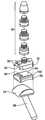
- FIG. 4Ais a perspective exploded view of a multi-piece tibial stem that, when assembled, is sized and configured to support a tibial artificial joint surface of a type shown in either FIG. 2 or FIG. 3 .
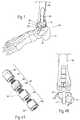
- FIG. 4Bis an assembled side view of the multi-piece tibial stem shown in FIG. 4A being installed in a tibia and supporting a tibial artificial joint surface in association with a talar artificial joint surface.
- FIG. 5is an anatomic side view of a total ankle replacement system comprising articulating ball-and-socket artificial joint surfaces.
- FIG. 6is a side anatomic view of articulating artificial joint surfaces that comprise complementary ball-and-socket surfaces that not only articulate, but also allows the artificial joint to rotate about the tibial axis.
- FIG. 7Ais an exploded perspective view of articulating artificial joint surfaces that comprise complementary ball-and-socket surfaces that not only articulate and rotate about the tibial axis, but also accommodate fore and aft and lateral translation of the mating joint surfaces relative to the tibia.
- FIGS. 7B and 7Care side anatomic view of articulating artificial joint surfaces shown in FIG. 7A when assembled and installed for use.
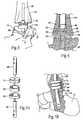
- FIGS. 8A , 8 B, and 8 Care the articulating tibial and talar surfaces 22 and 24 are perspective views of articulating artificial joint surfaces that each comprise a saddle-shaped component, with arrows provided in FIGS. 8B and 8C showing the articulation of the surfaces during up-and-down flexing of the foot ( FIG. 8B ) and side-to-side flexing of the foot ( FIG. 8C ).
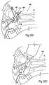
- FIG. 9is a perspective view of the saddle-shaped talar artificial joint surface secured in a snap-fit fashion to a talar stem having a configuration shown in FIG. 3 .
- FIG. 10is an exploded perspective view of the saddle-shaped talar artificial joint surface and talar stem shown assembled in FIG. 9 .
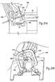
- FIG. 11is an anatomic View that illustrates a representative technique for drilling the anterior head of the talus from a posterior joint entry to install a talar stem of the type shown in FIG. 3 and FIG. 9 .
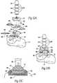
- FIG. 12Ais a perspective exploded view of a total ankle replacement system that includes a tibial component that articulates with a talar component having a talar artificial joint surface that can comprise a plastic material, e.g., ultra high molecular weight polyethylene, and that can be assembled in an interlocking fashion on a talar stem.
- a plastic materiale.g., ultra high molecular weight polyethylene
- FIG. 12Bis a perspective assembled view of the total ankle replacement system shown in FIG. 12A .
- FIG. 12Cis a section view taken generally along line 12 C in FIG. 12B .
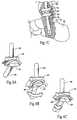
- FIG. 13is a perspective exploded view of a tibial component having a tibial artificial joint surface that can comprise a plastic material, e.g., ultra high molecular weight polyethylene, and that can be assembled in a sliding snap fit fashion on a tibial stem, which is shown to be a multi-piece stem of a type shown in FIG. 4A .
- a plastic materiale.g., ultra high molecular weight polyethylene
- FIG. 14is a perspective view of the underside of a platform that forms a part of the tibial component shown in FIG. 13 , the platform accommodating a sliding snap fit with the plastic tibial artificial joint surface.
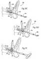
- FIGS. 15A , 15 B, and 15 Care side sections views of the platform shown in FIG. 14 making a sliding snap fit with the plastic tibial artificial joint surface.
- FIGS. 15D , 15 E, and 15 Fare perspective views of an installation tool being manipulated to male the sliding fit between the plastic tibial artificial joint surface and the platform as shown in FIGS. 15A , 15 B, and 15 C.
- FIG. 16is a side section view of the tibial component shown in FIG. 13 , after assembly.
- FIG. 17is a perspective view of the tibial component shown in FIG. 13 , after assembly, and in articulation with a talar component.
- FIG. 18is a perspective anatomic view of a native ankle joint, showing the three natural X, Y, and Z axes of the joint.
- FIG. 19is a perspective view of an alignment tool, which serves the task of aligning an ankle joint with the tibia during a procedure which installs a total ankle replacement system of a type shown in previous figures.
- FIG. 20is an exploded perspective view of a footholder assembly that forms a part of the alignment tool shown in FIG. 19 .
- FIGS. 21A and 21Bare assembled perspective views of the footholder assembly shown in FIG. 20 , showing its ranges of horizontal and vertical movement that make possible horizontal and vertical alignment of the leg and ankle joint radiologically.
- FIGS. 22A and 22Bare, respectively, side and end views of the footholder assembly shown in FIGS. 21A and 21B , showing the range of vertical movement that makes possible vertical alignment of the leg and ankle joint radiologically.
- FIGS. 23A and 23Bare, respectively, top and end views of the footholder assembly shown in FIGS. 21A and 21B , showing the range of horizontal movement that makes possible horizontal alignment of the leg and ankle joint radiologically.
- FIG. 24is a side view of representative tools and methodologies, which serve the task of establishing an in-line intramedullary path through the calcaneus, talus, and tibia.
- FIG. 25Ais a top view of representative tools and methodologies, which serve the purpose of establishing anterior access to the ankle joint for the purpose of malting bony cuts in the talus and tibia to clear a joint space for installation of the tibial and talar prosethesis platforms.
- FIGS. 25B and 25Care side views of the representative tools and methodologies shown in FIG. 25A in use to make bony cuts in the talus and tibia to clear a joint space for installation of the tibial and talar prosethesis platforms.
- FIG. 26is a top perspective view of the tools and methodologies shown in FIG. 25A in use to make bony cuts in the talus and tibia to clear a joint space for installation of the tibial and talar prosethesis platforms.
- FIGS. 27A and 27Bare side views of representative tools and methodologies, which serve the purpose of establishing an intramedullary passage within the tibia, into which the stem component of the tibial platform can be installed, making use of anterior access through the cleared joint space formed using the tools and methodologies of FIGS. 25A , 25 B, 25 C, and 26 .
- FIGS. 28A to 28Eshow in perspective views representative tools and methodologies, which serve the purpose of establishing a talar-calacaneal passage bridging the talus and calcaneus, in which the stem component of the talar platform 20 be installed making use of the anterior access through the cleared joint space formed using the tools and methodologies of FIGS. 25A , 25 B, 25 C, and 26 .
- FIGS. 29A to 29D and FIG. 30show in perspective views representative tools and methodologies, which serve the purpose of installing the multi-piece tibial stem (as also shown in FIGS. 4A and 4B ) and platform, the stem being assembled in situ in the intramedullary passage formed within the tibia formed using the tools and methodologies shown in FIGS. 27A and 27B .
- FIG. 31shows in a side view the installation of the calcaneal stem component into the passage bridging the talus and calcaneus (see FIG. 28E ) formed using the tools and methodologies shown in FIGS. 28A to 28E .
- FIG. 32shows in a side view the placement of the talar artificial joint surface on the calcaneal stem component installed using the tools and methodologies shown in FIG. 31 .
- FIG. 33shows in a side view the installation of the tibial artificial joint surface on the platform installed using the tools and methodologies shown in FIGS. 29A to 29D and FIG. 30 .
- FIG. 34is a left side perspective view of a representative installation platform to which a variety of jigs, fixtures, reamers, and auxiliary platforms of the form, fit, and function shown in FIGS. 19 to 33 may be rigidly and simply affixed to the sequence of tasks, including (i) the alignment of the ankle joint with the tibia, (ii) the establishing of an in-line intramedullary path through the calcaneus, talus, and tibia; (iii) the establishing of anterior access for the purpose of making properly oriented bony cuts in the talus and tibia to install the tibial and talar platforms; and (iv) the installation of the tibial and talar platforms.
- FIG. 35is a right side perspective view of the installation platform shown in FIG. 34 .
- Section Iintroduces the reader to the anatomy of the lower leg and ankle, to set the anatomic backdrop of the total ankle replacement systems and methods that will be described.
- Section IIprovides structural descriptions of representative embodiments of the tibial and talar-calcaneal components of total ankle replacement systems and devices that have the desired form, fit, and function.
- Section IIIprovides descriptions of representative embodiments of systems, methods, and techniques useful for the implantation of total ankle replacement systems and devices to achieve their desired form, fit, and function.
- the footcomprises fourteen phalanges or toe bones 11 connected to the metatarsus bones 13 .
- There are also seven tarsal bones 14of which the talus 15 supports the tibia 16 and the fibula 18 , and the heel bone or calcaneus 17 .
- the talus 15 and the calcaneus 17are the largest and are adjacent to each other.
- the other tarsal bonesinclude the navicular 19 , three cuneiforms 21 , and the cuboid 23 .
- FIG. 2shows a total ankle replacement system 10 .
- the system 10includes a tibial platform 12 that is sized and configured for installation on the tibia 16 .
- the tibial platform 12desirably includes a tibial stem 28 .
- the systemalso includes a talar platform 20 that is sized and configured for installation on the talus 15 .
- the talar platform 20includes a talar stem 26 .
- the tibial platform 12carries a tibial artificial joint surface 22 .
- the talar platform 20carries a talar artificial joint surface 24 .
- the tibial artificial joint surface 22 and the talar artificial joint surface 24are bearing surfaces mutually sized and configured to articulate.
- the articulating joint surfaces 22 and 24replace the natural ankle joint surfaces, which are removed (as will be described later), to restore a range of motion that mimics the natural joint.
- the joint surfaces 22 and 24may be made of various materials commonly used in the prosthetic arts including, but not limited to, polyethylene, high molecular weight polyethylene (HMWPE), rubber, titanium, titanium alloys, chrome cobalt, surgical steel, or any other total joint replacement metal and/or ceramic, bony in-growth surface, sintered glass, artificial bone, any uncemented metal or ceramic surface, or a combination thereof.
- the joint surfaces 22 and 24may comprise different materials.
- the tibial joint surface 22may comprise a plastic or other non-metallic material
- the talar joint surfacecomprise a metallic material.
- the surfaces 22 and 24may each comprise the same type of materials (i.e., metal-metal or plastic-plastic).
- the tibial platform 12 , the talar platform 20 , and/or the articulating artificial joint surfaces 22 and 24 they carrymay be variously configured and posses various technical features. Representative examples of configurations and features will now be described.
- the talar stem 26may be variously sized and configured. As shown in FIG. 2 , the stem 26 bridges the talus to the calcaneous. This stem 26 serves the dual function of supporting the talar platform as well as fusing the sub-talar joint, should that be necessary or beneficial to the patient.
- the replacement system 10incorporates many technical features disclosed in Reiley U.S. Pat. No. 6,663,669.
- the talar platform 20is fixed to the calcaneus 17 and/or the talus 15 , which can increase the amount of bone available for fixation.
- the fusion of the subtalar joint that the stem 26 providesallows fixation of the talar platform 20 to both the talus 15 and calcaneus 17 .
- the subtalar jointcan be fused using any method common to those of skill in the surgical arts including, but not limited to, fusion with poly(methylmethacrylate) bone cement, hydroxyapatite, a ground bone and marrow composition, plates and screws, or a combination thereof.
- the enlarged available bone baseprovides prosthesis stability, and allows for anchoring of the talar platform 20 with, for example, screws. This design provides stability and stress absorption for the overall prosthetic ankle joint, and decreases the probability of prosthesis loosening and subsidence.
- prosthesis systems with talar stems 26 that do not bridge the talus to calcaneouscan also offer stability, reliable fixation, and longevity.
- the talar stem 26 shown in FIG. 3does not bridge the talus to the calcaneous. Instead, the stem 26 projects from posterior to anterior of the ankle into the anterior head of the talus.
- the talar headis a large bony component of the talus, which offers a substantial bony structure to affix the talar platform 20 .
- the subtalar jointcan be still be fused separately, if desired, using any methods just mentioned.
- any given talar stem 26may be made of various materials commonly used in the prosthetic arts including, but not limited to, titanium, titanium alloys, tantalum, chrome cobalt, surgical steel, polyethylene, absorbable polymer, or any other total joint replacement metal and/or ceramic, bony in-growth surface, sintered glass, artificial bone, any uncemented metal or ceramic surface, or a combination thereof.
- the talar stem 26may further be covered with various coatings such as antimicrobial, antithrombotic, and osteoinductive agents, or a combination thereof. These agents may further be carried in a biodegradable carrier material with which the pores of the surface of the talar stem 26 may be impregnated. See U.S. Pat. No. 5,947,893, which is incorporated herein by reference.
- the talar stem 26may be coated and/or formed from a material allowing bony ingrowth, such as a porous mesh, hydroxyapetite, or other porous surface.
- the talar stem 26may be any size or shape deemed appropriate and is desirably selected by the physician taking into account the morphology and geometry of the site to be treated.
- the physicianis desirably able to select the desired size and/or shape based upon prior analysis of the morphology of the target bone(s) using, for example, plain film x-ray, fluoroscopic x-ray, or MRI or CT scanning.
- the size and/or shapeis selected to optimize support and/or bonding of the stem 26 to the surrounding bone(s).
- the stem 26may be variable lengths from 2 cm to 12 cm and variable widths from 4 to 14 mm.
- a talo-calcaneal stem 26is approximately 65 to 75 mm in length and approximately 7 to 13 mm wide.
- the stemhas a circular cross-section
- the stemcould formed in various other cross-sectional geometries, including, but not limited to, elliptical, polygonal, irregular, or some combination thereof.
- the stemcould be arched to reduce and/or prevent rotation, and could be of constant or varying cross-sectional widths.
- the talar stem 26may be with poly(methylmethacrylate) bone cement, hydroxyapatite, a ground bone composition, screws, or a combination thereof, or any other fixation materials common to one of skill in the art of prosthetic surgery.
- the talar stem 26may additionally have interlocking components, along its length or at its top surface to assemble the stem 26 in situ and/or allow other components of the talar platform 20 to lock and/or fit into the talar stem 26 .
- the tibial stem 28may be made of any total joint material or materials commonly used in the prosthetic arts, including, but not limited to, metals, ceramics, titanium, titanium-alloys, tantalum, chrome cobalt, surgical steel, polyethylene, absorbable polymer, or any other total joint replacement metal and/or ceramic, bony in-growth surface, sintered glass, artificial bone, any uncemented metal or ceramic surface, or a combination thereof.
- the tibial stem 28may further be covered with one or more coatings such as antimicrobial, antithrombotic, and osteoinductive agents, or a combination thereof. These agents may further be carried in a biodegradable carrier material with which the pores of tibial stem 28 may be impregnated. See U.S. Pat. No. 5,947,893.
- the tibial stem 28may be fixed into the tibia with poly(methylmethacrylate) bone cement, hydroxyapatite, a ground bone composition, screws, or a combination thereof, or any other fixation materials common to one of skill in the art of prosthetic surgery.
- the tibial stem 28is fixed to the tibia 16 with screws. If screws are used, they can extend anteriorly, posteriorly, medially, laterally and/or at oblique angles, or any combination thereof.
- the tibial stem 28may be variable lengths from 20 mm to 300 mm and variable widths from 6 mm to 20 mm. In the preferred embodiment, the tibial stem 28 is preferably at least 50 mm in length. Of course, it should be understood that the disclosed tibial stem 28 could be of virtually any length, depending upon the size of the patient, his or her bone dimensions, and the anticipated future mobility of the patient. In general, a larger patient, having larger bones, with a high anticipated mobility (i.e. he or she will be walking/running around quite a bit) would desirably have a longer stem 28 to provide increased stability and broader distribution of stress to prevent subsidence, loosening, and tibial osteolysis.
- the stem 28can incorporate an anti-rotational feature such as outwardly extending fins—for example, one or more fins, 0.5 to 25 cm long, 1 to 3 mm wide, sharp edges or dull, located along the stem 28 —or a bow to the stem 28 —for example, ranging from 1 to 10 degrees bow, anterior or posterior or lateral, or some combination thereof.
- the surface of the tibial stem 28can incorporate irregularities such as wedges or points, desirably angled towards the knee, which inhibit and/or prevent the tibial stem 28 from subsiding.
- the width of the tibial stem 28may vary along the length of the stem 28 , further inhibiting and/or preventing rotation and/or subsidence.
- the tibial stem 28may additionally have interlocking components along its length and/or at its lower surface to allow assembly the stem 28 in situ and/or allow other components of the tibial platform 12 to lock into the tibial stem 28 .
- FIG. 4Aillustrates a multi-piece tibial stem 30 suitable for use in any surgical procedure in which a stem is required for fixation of an implant, whether it is a total joint implant, fusion (arthrodesis) implant, osteotomy fixation implant, or fracture fixation implant.
- the stem 30comprises a top (i.e., superior) component 32 , one or more mid components 34 , and a bottom (i.e., inferior) component 36 .
- the top component 30is desirably convex or domed to facilitate advancement of the stem 30 in the direction of the top component 32 within bone.
- the multi-piece configurationis ideally suited for securing bone components together in a minimally invasive procedure.
- This configurationis also ideally suited for minimally invasive surgeries in which a small surgical opening is used to install large components.
- This configurationallows a small surgical opening to be used to install large components at generally a right angle to or transverse the direction of insertion of the individual stem components 32 / 34 / 36 .
- This aspect of the multi-piece stem 30will be very apparent after discussion of representative surgical procedure later.
- Two or more small stem components 32 / 34 / 36can be sequentially attached to one another in situ (see FIG. 4B ) to make a larger stem assembly.
- a top component 32may be joined with a bottom component 36 .
- one or more mid components 34may be placed between the top and bottom components 32 and 36 to form a stem 30 of a desired length.
- the components 32 / 34 / 36may be screwed together, as shown, or attached with a Morse taper, one-quarter turn, or other fixation means.
- the stem segments 32 / 34 / 36can be fitted together with a combination of Morse tapers and threads, or with a combination of Morse tapers and external pins or screws.
- one or more of the components 32 / 34 / 36may include an internal hex 38 or other non-rotation configuration for engagement with a driver or other tool to facilitate advancement of the component 32 / 34 / 36 within bone and/or to torque the component 32 / 24 / 36 into the adjacent component 32 / 34 / 36 , as shown in FIG. 4A .
- one or more of the components 32 / 34 / 36may also include an external hex 40 or other non-rotation configuration for engagement with a wrench or other tool to grasp or otherwise secure the component 32 / 34 / 36 during installation.
- each component 32 / 34 / 36is desirably sized and configured to be individually installed through a small incision, e.g., a small anterior opening in the ankle.
- the individual components 32 / 34 / 36can be sequentially joined together in situ, e.g., within an intramedullary path in the tibia (which has been reamed-out in advance) and progressively advanced up the intramedullary path, top component 32 first.
- the last or bottom component 36is sized and configured to attach to a prosthesis (e.g., the tibial platform 12 ) that would comprise the upper half of the ankle prosthesis.
- the multi-piece configurationnot only permits installation using minimally-invasive procedures, but provides a means to install long fixation members or stems that might not be achievable if they were constructed of a single piece.
- the multi-piece stem 30While the long or extended length of the multi-piece stem 30 is particularly well-suited for use in the tibia, the multi-piece stem 30 could be used in other long bones or in the talus as well.
- the articulating artificial joint surfaces 22 and 24may be made of materials such as plastic (e.g., polyethylene), ceramic, or metal, or combinations thereof (e.g., metal-backed plastic). They may possess various configurations and articulate in different ways. Various representative embodiments will now be described for purpose of illustration.
- the basic geometry of the articulating surfaces 22 and 24can form a ball-and-socket joint.
- the articulating surfaces 22 and 24comprise mating concave and convex surfaces.
- the tibial artificial joint surface 22comprises a concave dome
- the talar artificial joint surface 24comprises a convex dome that, when installed, mates with the concave dome. This mimics the configurations of the natural joint surfaces they replace.
- the convex dome of the talar surface 24can comprise a button-like structure that can be installed in a reamed-out pocket within the talus 15 , without the use of a stem 26 .
- the button-like structurecan be secured within the pocket without use of a stem 26 with poly(methylmethacrylate) bone cement, hydroxyapatite, a ground bone composition, screws, or a combination thereof, or any other fixation materials common to one of skill in the art of prosthetic surgery.
- the button-like structurecan include a peg 40 or similar appendage in lieu of a stem per se.
- the tibial surface 22is secured to a stem 28 by a Morse taper connection that does not permit movement of the surface 22 relative to the stem 28 .
- FIG. 6illustrates an embodiment in which the articulating surfaces 22 and 24 comprise complementary ball-and-socket surfaces that not only articulate, but also allows the artificial joint to rotate about the tibial axis. This makes possible more uniform wear of the surfaces 22 and 24 to maximize function and longevity of the prostheses.
- the basic geometry of the articulating surfaces 22 and 24comprises a ball-and-socket joint.
- the tibial artificial joint surface 22comprises a concave dome
- the talar artificial joint surface 24comprises a convex dome that, when installed, mates with the concave dome.
- the talar artificial joint surface 24is carried by a stem 26 .
- the surface 22is fixed to the stem 26 by a Morse-taper connection, so that no relative movement can occur between this surface 22 and the talus.
- the tibial artificial joint surface 22is carried by a platform 12 .
- the platform 12is, in turn, coupled to a tibial stem 28 by a Morse taper connection. No rotation between the platform 12 and the stem 28 can occur.
- the connection between the platform 12 and the joint surface 22comprises a rotational fit. This fit is achieved between a cylindrical collar 23 depending from the platform 46 that nests within a mating trough 25 on the joint surface 22 .
- This rotation fitallows rotation of the surface 22 relative to the platform 12 about the axis of the stem 28 and thus about the axis of the tibia, to which the stem 28 is fixed.
- This rotational couplingmore freely accommodates rotation of the foot relative to the tibia, providing enhanced mechanical equilibrium and stability.
- FIGS. 7A , 7 B, and 7 Cillustrate an embodiment in which the articulating surfaces 22 and 24 comprise complementary ball-and-socket surfaces that not only articulate and rotate about the tibial axis, but also accommodate fore and aft and lateral translation of the mating joint surfaces relative to the tibia.
- the tibial artificial joint surface 22comprises a cup or socket-like surface
- the talar artificial joint surface 24comprises a ball-like surface that, when installed, mates with the cup-like surface of the tibial artificial joint surface 22 .
- the talar artificial joint surface 24is carried by a stem 26 .
- the surface 22is fixed to the stem 26 by a Morse-taper connection, so that no relative movement can occur between this surface 22 and the talus.
- the tibial artificial joint surface 22is carried by a platform 12 .
- the platform 12is, in turn, coupled to a tibial stem 28 by a Morse taper connection. No rotation between the platform 12 and the stem 28 can occur.
- the connection between the platform 12 and the joint surface 22comprises a loose, non-interference fit between an oversized hole 42 in the joint surface 22 and a lesser diameter tab 44 on the platform 12 .
- This loose couplingpermits relative lateral (side-to-side) as well as anterior-to-posterior sliding or translation between the platform 12 and the joint surface 22 (see FIG. 7C ), as well as intermediate ranges of diagonal movement.
- the loose couplingalso allows rotation of the surface 22 relative to the platform 12 about the axis of the stem 28 .
- This loose couplingaccommodates forward and sideways translation of the foot relative to the tibia, as well as rotation of the foot relative to the tibia.
- This featuremakes possible uniform wear and uses all the surface area to the fullest extent to maximize function and longevity of the prostheses.
- the translating ball and socket type articulationprovides mechanical equilibrium and stability.
- the articulating spherical surfaces 22 and 24maximize the contact area, thereby minimizing the contact pressure. This minimizes local surface stresses, in turn, minimizing wear on the joint and maximizing joint longevity.
- the ball jointmaximizes joint mobility. It accommodates the normal flexure of the ankle during walling or running. It also allows for the normal side to side rotation of the normal ankle.
- Previous embodimentsshow, as the basic articulating geometry, ball and socket joints.
- the articulating tibial and talar surfaces 22 and 24are shown to each comprise a saddle-shaped component.
- the saddle shapeis geometrically characterized as a swept arc (which is of constant radius in a preferred embodiment), comprising a surface defined by a first arc (which is of constant radius in a preferred embodiment) that is swept along a second arc (which is also of constant radius in a preferred embodiment) that is perpendicular to the first arc.
- the geometryforms, for each surface 22 and 24 , an elongated trough that curves along an axis.
- the trough of the tibial saddle surface 22 componentnests within the trough of the talar saddle surface 24 .
- An interfaceis thereby formed between the tibial and talar components of the prosthesis.
- the articulationoccurs along this interface both along the curved axis of the trough, i.e. accommodating up and down flexing of the foot (see FIG. 8B ), as well as transversely within the tough, i.e., accommodating lateral (side to side) flexing of the foot (see FIG. 8C ).
- the saddle interfaceprovides the joint with intrinsic stability, as the joint wants to assume a position of stable static equilibrium. Some patients will require a deep saddle trough because the surrounding soft tissue supports for the ankle joint are compromised or weak. Other patients may require a less deep saddle trough because their joint has more supporting soft tissue. A more shallow saddle trough provides increased ability for the joint to rotate about the tibial axis, which is desirable.
- the saddle shaped tibial surface 22can be sized and configured to be fixed to a tibial stem 28 in any of the manners previously described.
- the stem 28can comprise comprises a multi-piece stem 30 as earlier described and as shown in FIG. 4A .
- the talar componentis desirably installed after the tibial component has been inserted into the joint.
- the talar componentcan be sized and configured in various ways.
- the talar platform 20is secured to a talar stem 26 having a configuration shown in FIG. 3 , i.e., the stem 26 does not bridge the sub-talar joint, but projects from posterior to anterior into the anterior head of the talus 15 .
- FIG. 11illustrates a representative technique for drilling the anterior head of the talus 15 from a posterior joint entry to install the talar stem 26 .
- a k-wire 52is used to pierce from within the joint, in an anterior to posterior-lateral direction. The foot is then placed in the dorsi-flexion position, as shown.
- a conventional cannulated trocar(not shown) is placed over the k-wire 52 and advanced to pierce the joint in a posterior to anterior direction.
- a cannula 54is passed over the trocar, and the trocar is removed. The cannula 54 remains, establishing a percutaneous path to the talus 15 .
- a cannulated drill 56is placed over the k-wire 52 within the cannula 54 .
- the anterior head of the talus 15is drilled to the proper depth to receive the stem 26 .
- the stem 26is inserted.
- the talar platform 20is secured to the stem 26 and nests on top of the talus 15 , which has been milled beforehand.
- the proximal end 76 of the stem 26includes a male hex 78 , or other non-rotation configuration, that nests in a female hex 80 on the bottom 74 of the talar platform 20 .
- a cap screw 82proceeding through the talar platform 20 into the talar stem 26 , affixes the stem 26 and platform 20 together.
- the saddle shaped talar artificial joint surface 24snaps into the top of the talar platform 20 and rests in a load bearing nest defined by the platform 20 .
- a pair of opposing tabs or protrusions 68 from both sides of the talar artificial joint surface 24nest in slots 70 in raised pillars 72 on the talar platform 20 , further ensuring that the surface 24 is well secured to the talar platform 20 .
- the snap-together interlocking configurationprovides for easily removal and replacement of the talar artificial joint surface 24 .
- a sizing-piecemade of plastic or other suitable biocompatible material, can be slid into the joint space so the physician can determine the proper thickness of material to provide the proper joint distention.
- the physicianslides the actual talar artificial joint surface 24 into the joint space and snap-fits it onto the platform 20 .
- the talar artificial joint surface 24can be formed of a durable biocompatible plastic, e.g., Ultra High Molecular Weight Polyethylene (UHMWPE). Placement of a plastic component on the talar side rather than on the tibial side provides the maximum amount of plastic material available for strength and wear properties, while at the same time allowing for the minimal amount of bone removal.
- UHMWPEUltra High Molecular Weight Polyethylene
- FIGS. 12A and 12BAnother representative embodiment of a plastic talar-side component is shown in FIGS. 12A and 12B .
- the componentshares many of the features of the component just described.
- the joint surface 24rests on the platform 20 upon a pair of spacing leg plates or spacers 58 .
- the spacers 58are placed under the talar artificial joint surface 24 on opposing sides of the surface 24 (see FIG. 12C ).
- the spacers 58include upwardly arched sides that nest within tabs 59 extending beneath the arched edges of the saddle-shaped joint surface 24 .
- a locking plate 60fits on the platform 20 beneath the spacers 58 upon which the talar artificial joint surface 24 rests.
- Flanges 66 projecting from sides of the locking plate 60lock into slots 61 on the talar platform 20 .
- the thickness and configuration of the spacers 58 and plate 60can be varied to accommodate individual patient needs and anatomy.
- the spacers 58 and locking plate 60are each approximately 1-2 mm thick.
- the locking plate 60is sized and configured with a memory to serve as a spring-lock. All the components of the talar assembly are frictionally locked together, like a rubix cube, without the use of screws or other mechanical fasteners.
- the frictionally interlocking designprovides stability, as there are no induced forces tending to drive the components from the joint space, because they are all interlocked.
- the anterior-posterior and medial-lateral forces on the talar componentmay be substantial, but the talar joint surface 24 is trapped-locked within the talar platform 20 sidewalls and securely held in place.
- the snap-together interlocking system just describedprovides a positive locking means without the use of screws or other means.
- the interlocking designalso provides the physician with a relatively simple means to replace the talar artificial joint component 24 if it wears out.
- the physicianmakes a small anterior opening in the ankle to access the joint.
- the physicianthen removes the locking plate 60 and spacers 58 and withdraws the worn component 24 .
- a new component 24is inserted and locked into place.
- a snap-fit assemblycan also be incorporated into a tibial component.
- a tibial platform 12includes a tibial stem 30 , which is shown to comprise a multi-piece stem as earlier described and as shown in FIG. 4A .
- the tibial platform 12 and the stem 30desirably comprise metal parts.
- the tibial platform 12carries a tibial artificial joint surface 22 .
- the joint surface 22is desirable made from a durable biocompatible plastic, e.g., Ultra High Molecular Weight Polyethylene (UHMWPE).
- UHMWPEUltra High Molecular Weight Polyethylene
- the plastic selected for the joint surface 22is resiliently deformable, meaning that it will temporarily yield or bend in response to an applied force, but it will not permanently deform, but rather will return to its normal configuration when the force is removed.
- the joint surface 22can be sized and configured to be snap-fitted to the platform 12 .
- alternative snap-fit assembliescould comprise a metal joint surface 22 and a resilient platform 12 , or resilient platform 22 and a resilient joint surface 12 .
- the platform 12includes oppositely spaced, inwardly tapered side rails 90 .
- the side rails 90extend in an anterior to posterior direction along the underside of platform 12 .
- the tapered side rails 90form a channel 92 between them.
- the topside of the artificial joint surface 22includes a tab member 94 .
- the tab member 94is sized and configured to nest within the channel 92 , by sliding the tab member 94 into the channel 92 in an anterior to posterior direction, as FIGS. 15A to 15C show.
- the underside of the platform 12includes a shaped depression or notch 96 near its anterior edge.
- the topside of the artificial joint surface 22includes an upwardly projecting lobe or detent 98 near its anterior edge.
- the detent 98is sized and configured to rest within the notch 96 .
- the underside of the platform 12desirably includes a stop flange 190 along its posterior edge.
- the joint surface 22includes a mating proximal groove 192 , which nests against the stop flange 190 to prevent over-travel of the joint surface 22 relative to the platform when caused to slide in a posterior direction.
- the engagement of the stop flange 190 and groove 92is sized and configured to occur in concert with the snap-fit engagement of the detent 98 within the notch 96 .
- an installation tool 300can be provided to aid in sliding the joint surface 22 into fitment with the platform 12 .
- the installation tool 300includes a body 302 defining a channel 304 in which a manually operable plunger 306 is carried for fore and aft sliding movement. With the plunger 306 pulled back into its most-aft position (see FIG. 15D ), the joint surface 22 can be loaded into the channel 304 , detent 98 -side first (the tab member 94 slides within side rails that line the channel 304 ). The joint surface 22 is placed into abutment with the plunger 306 within the channel 304 .
- the platform 12is coupled to the distal end of the body 302 (e.g., with a mounting screw 312 carried on the distal end of the body 302 that engages a threaded receptacle 314 on the platform 12 , along with an anti-rotational holding pin 308 on body 302 that fits within an aperture 310 on the platform 12 ).
- the body 302holds the channel 92 of the platform 12 in alignment to accept the tab member 94 of the joint surface 22 .
- FIG. 15Fshows, forward advancement of the plunger 306 pushes the joint surface 22 , expelling it from the body channel 304 and into the platform channel 92 , until the notch 96 and detent 98 engage (as FIG. 15C shows).
- Disengaging the screw 312 from the receptacle 314 and pulling back on the tool 300disengages the holding pin 308 from the aperture 310 , freeing the tool 300 from the now-assembled tibial component.
- the tab member 94 of the joint surface 22is captured within the side rails 90 of the platform 12 ; the detent 98 if the joint surface 22 is captured within the notch 96 of the platform; and the proximal groove 192 of the joint surface 22 is captured within the stop flange 190 of the platform 12 .
- the joint surface 22is held securely within the platform 12 , which is, in turn, fixed in position by the stem 30 .
- the joint surface 22is thereby positioned for stable articulation with a talar artificial joint surface 24 (see FIG. 17 ), which is, in turn, fixed in position by a stem 26 .
- the ankle replacement system 10is installed using minimally invasive intramedullary guidance.
- Intramedullary guidanceis established with respect to the major axis of the tibia by minimally invasive access through the calcaneus, through an incision in the bottom of the foot.
- Intramedullary guidance along the axis of the tibiamakes it possible to make properly oriented bony cuts of the talus 15 and tibia 16 through anterior access to the ankle joint. Proper overall alignment of the total ankle system 10 and improved long term results are achieved.
- the total ankle system 10can be installed in desired alignment and orientation with all the natural axes of the native ankle joint it replaces.
- FIG. 18shows these natural axes to include the anterior to posterior axis (Y-horizontal axis) of rotation of the ankle joint, the natural medial-to-lateral axis (X-horizontal axis) of rotation of the ankle joint, and the natural superior-to-inferior axis (Z-vertical axis) of alignment of the ankle joint with the major axis of the tibia.
- the ankle replacement system 10By establishing and maintaining proper alignment of the anterior to posterior axis (Y-horizontal axis) of rotation, the ankle replacement system 10 establishes and maintains the desired degree of plantar-dorsi (“up and down”) flexion of the foot. By establishing and maintaining proper alignment of the natural medial-to-lateral axis (X-horizontal axis) of rotation, the system 10 establishes and maintains the desired degree of inversion/eversion (“in and out”) rotation of the foot.
- the system 10By establishing and maintaining proper alignment of the natural superior-to-inferior axis (Z-vertical axis) of alignment of the ankle joint with the long axis of the tibia, the system 10 is accurately oriented with respect to the central tibial axis of the leg, so that intramedullary support can be achieved by in line drilling of the calcaneous 17 and talus 15 in a single drilling step using fluoroscopic guidance.
- ankle replacement proceduresi.e., the installation of a prosthetic replacement for either or both of the tibial and talar ankle joint surfaces
- procedures involving fusions in an ankle replacement proceduree.g., subtalar fusions, pan-talar fusions, or triple arthrodeses.
- the representative installation tools, systems, methodsaccomplish the tasks of (i) the alignment of the ankle joint with the tibia, (ii) the establishing of an in-line intramedullary path through the calcaneus, talus, and tibia; (iii) the establishing of anterior access for the purpose of making properly oriented bony cuts in the talus and tibia to install the tibial and talar platforms 12 and 20 ; (iv) the installation of the tibial and talar platforms 12 and 20 .
- FIG. 19shows a representative alignment tool 100 , which serves the task of the alignment of the ankle joint with the tibia during a prosthesis installation procedure.
- the alignment tool 100includes a footholder assembly 102 and a leg rest 104 .
- the footholder assembly 102includes a foot rest 106 , to which the foot is secured by a foot clamp 106 and heel clamps 108 during an prosthesis installation procedure.
- the calf of the legis suitably secured to the leg rest 104 .
- the footholder assembly 102 and the leg rest 104hold the foot and ankle relative to the leg during an installation procedure.
- the footholder assembly 102is sized and configured for pivoting, under control of the physician, from a vertical or upright condition (shown in solid lines in FIG. 19 ) toward a more horizontal or tilted condition (shown in phantom lines in FIG. 19 ).
- the assembly 102serves to hold the ankle joint in a desired orientation with respect to the natural arterial-to-posterior and medial-to-lateral axes.
- the ankle replacement system 10establishes and maintains proper stress distributions through the walking gait.
- the assembly 102can be pivoted in a controlled fashion to cause flexion of the ankle joint, if and when desired during the installation procedure.
- the footholder assembly 102can be locked by the physician in any desired orientation between the full upright condition and full pivoted condition.
- the footholder assembly 102also allows the ankle joint to be precisely oriented and maintained, using fluoroscopy, in a desired alignment with the major axis of the tibia.
- the footholder assembly 102includes, in addition to the foot rest 106 , a back plate 112 and mid-plate 114 , which is sandwiched between the foot rest 106 and the back plate 112 .
- the mid-plate 114is coupled to the foot rest 106 by sliding dovetail couplings 116 for up-and-down (vertical) movement relative to the foot rest 106 .
- a pair of oppositely spaced alignment rods 118is carried by the mid-plate 114 .
- the alignment rods 118lay in the same horizontal plane.
- the alignment rods 118extend from the mid-plate through vertically elongated slots 120 in the foot rest 106 , so that, in use (see FIG. 19 ) the rods 118 lay on opposite sides of the tibia in the medial-to-lateral plane. Vertical movement of the mid-plate 114 moves the alignment rods 118 up-and-down in unison within the slots 120 on opposite sides of the foot rest 106 (see FIG. 21B ).
- the back plate 112is coupled to the mid-plate 114 by sliding dovetail couplings 122 for side-to-side (horizontal) movement relative to the foot rest 106 .
- a pair of oppositely spaced alignment rods 124is carried by the back plate 112 .
- the alignment rods 124lay in the same vertical plane.
- the alignment rods 124extend from the back plate 112 above and below the foot rest 106 , so that, in use (see FIG. 19 ) the rods 124 lay on opposite sides of the tibia in the anterior-to-posterior plane. Horizontal movement of the back plate 112 moves the alignment rods 124 side-to-side in unison above and below the foot rest 106 (see FIG. 21A ).
- the back plate 112also carries a bushing 126 .
- the bushing 126extends through openings 128 in the mid-plate 114 and foot rest 106 and terminates at or near the plane of the foot rest 106 against which the bottom of the foot contacts.
- the center of the bushing 126coincides with the intersection of the horizontal plane of the rods 118 and the vertical plane of the rods 124 .
- the rods 118 and 124are made of materials that are visualized by fluoroscopy.
- the leg and footare prepped for surgery.
- the physiciandesirably makes an anterior incision to gain initial access to the ankle joint.
- the foot and lower legare placed in the foot rest 106 and leg rest 104 .
- the physicianestimates the ankle's axis of dorsi-plantar rotation and visually aligns the ankle to the axis of rotation of the alignment tool 100 .
- the foot rest 106is adjusted to rotate the foot so that the big toe is pointing essentially vertically.
- the forefoot and heelare secured to the foot rest 106 with the clamps 108 and 110 already described.
- the leg rest 104is adjusted to the calf so that the tibia 16 is approximately parallel to the floor.
- the foot and calfare desirably aligned so that the anterior-posterior (A-P) line of the talus's trochlea is essentially vertical.
- A-Panterior-posterior
- a fluoroscopy unit 130is aligned to the medial-lateral rods 118 .
- the rods 118appear as one in fluoroscopy.
- the physicianmoves the mid-plate 114 to align the rods 118 to the center axis (Z-axis) of the tibia 16 .
- Suitable manual or powered alignment controlscan be provided for this purpose.
- the mid-plate 112is locked to the foot rest 106 .
- the fluoroscopic unit 130is moved ninety degrees to an anterior to posterior position.
- the fluoroscopy unit 130is aligned to the anterior-to-posterior rods 124 .
- the rods 124appear as one in fluoroscopy.
- the physicianmoves the back plate 112 to align the rods 124 to the center axis (Z-axis) of the tibia 16 .
- Suitable manual or powered alignment controlscan be provided for this purpose.
- the back plate 112is locked to the foot rest 106 .
- FIG. 24shows representative tools 132 , and methodologies, which serve the task of establishing an in-line intramedullary path through the calcaneus, talus, and tibia.
- the tools 132include a bottom foot cannula 134 which establishes an intramedullary guide path through the calcaneus and talus that leads into the tibia.
- the bushing 126 on the back plate 112is slaved to alignment with the axis of the tibia by alignment of the rods 118 and 124 to the same anatomic target.
- the alignment tool 100as just described to align the ankle joint with the tibia
- in line drilling of the center of the ankle and tibia for introduction of the bottom foot cannula 134is made possible, because the bushing 126 has been aligned, by alignment of the rods 118 and 124 , to achieve the desired line-drilling position up through the bottom of the foot.
- the bushing 126is temporarily separated from the back plate 112 (e.g., by unscrewing) to provide access to the bottom of the foot.
- the physicianuses a scalpel to make an initial incision in the bottom of the foot, and the bushing 126 is replaced.
- a cannulated trocar loaded with a k-wire(not shown) can be inserted through the bushing 126 , into the bottom of the foot, until the calcaneous 17 is contacted and the k-wire is firmly set into the calcaneous 17 .
- the trocarcan then be removed, and the k-wire lightly tapped further into the calcaneous 17 .
- the bushing 126measures 6 mm in diameter
- the cannulated trocarcan be 6 mm loaded with a 2.4 mm k-wire.
- the physiciancan now operate a cannulated first reamer (e.g., 6 mm) (not shown) over the k-wire up into the calcaneous 17 and talus 15 approximately 30 mm.
- the first reameropens an access path for insertion of the bottom foot cannula 134 .
- the physiciancan now insert the bottom foot cannula 134 (as shown in FIG. 24 ).
- a second reamer 136e.g., 5 mm
- a second reamer 136can be operated through the cannula 134 to drill approximately another 100 mm through the talus 15 and up into the tibia 16 . Fluoroscopy may be used, if desired, to verify the accuracy of the drilled hole.
- An intramedullary guide pathhas been established through the calcaneus and talus leading into the tibia.
- the presence of the bottom foot cannula 134maintains the guide path in alignment with the axis of the tibia.
- FIGS. 25A , 25 B, 25 C and FIG. 26show representative tools 138 and methodologies, which serve the purpose of establishing anterior access to the ankle joint for the purpose of making bony cuts in the talus and tibia to install the tibial and talar platforms 12 and 20 .
- the tools 138include a cutting guide fixture 140 which is installed and stabilized over the ankle joint in an anterior position to the ankle joint.
- the cutting guide fixture 140is secured to an underlying frame 142 to which the alignment tool 100 is also attached.
- the cutting guide fixture 140includes a superior bone cutting blade guide 144 and an inferior bone cutting blade guide 146 .
- the cutting guide fixture 140also includes apertures for receiving fixation pins 148 adjacent the blade guides 144 and 146 .
- the pins 148can comprise 2.4 mm Steinmann pins. A pair of the pins 148 are drilled adjacent the superior blade guide 144 into the tibia 16 , and the other pair of the pins 148 are drilled into the talus 15 adjacent the inferior blade guide 146 . To maximize operating field space, the pins 148 may be cut flush at the fixture 140 , if desired. The operating field of the ankle joint is thereby stabilized, as shown in FIG. 25A .
- the cutting guide fixture 140also includes an aperture 150 for establishing an anti-rotational notch.
- the physiciancan form the anti-rotational notch, e.g., by using a drill and lock collar (e.g. 4 mm) operated through the aperture.
- a drill and lock collare.g. 4 mm
- FIG. 25Ashows, using fluoroscopy, the bottom foot cannula 134 is kept in the foot, but out of the way of superior blade guide 144 and the intended location of the anti-rotation notch 150 .
- the physicianWhen establishing the anti-rotational notch, the physician desirably notes from the drill the approximate depth of the underlying bone. On the superior and inferior saw blades 152 and 154 (see FIGS. 20B and 20C ), the physician notes the depth required based upon the previously measured drill depth.
- the superior saw blade 152is operated through the superior blade guide 144 to cut the top surface of the tibia 16 .
- bottom foot cannula 134Retaining the bottom foot cannula 134 within the foot while making bony cuts results an enhanced level of accuracy, because there is essentially no relative movement of the joint components during the drilling and sawing operations. Considerable force is often exerted upon the joint during drilling and sawing operations, which can move the joint out of the desired orientation for optimal prosthesis placement.
- the bottom foot cannula 134helps ensure the joint components maintain the correct alignment relative to one another so that the resulting cuts are more accurately positioned.
- the bottom foot cannula 134is then retracted out of the way of inferior blade guide 146 (see FIG. 25C ).
- the inferior saw blade 154is operated through the inferior blade guide 146 .
- the bottom surface of the talus 15is cut to the depth previously noted.
- the bottom foot cannula 134is reinserted into the foot and both sides of the joint space are cut using side saw blade guide slots 156 (see FIG. 25A ).
- FIG. 27Ashows the cleared joint space 158 and the anterior access it provides for the insertion of other installation tools and the components of the tibial and talar platforms 12 and 20 .
- both tibial and talar platforms 12 and 20include respective stem components. As previously described, these stem components provide enhanced fixation and support to the platforms. The creation of the passages for installation of these stem components in the tibia and talus will now be described.
- FIGS. 27A and 27Bshow representative tools 160 and methodologies, which serve the purpose of establishing an intramedullary passage within the tibia, into which the stem component of the tibial platform 12 can be installed, making use of anterior access through the cleared joint space 158 .
- the tools 160include a tibial stem driver 162 having a threaded end and a tibial stem reamer 164 , which can be removably screwed onto the threaded end of the driver 162 .
- the installation of the bottom foot cannula 134makes its possible to couple of the reamer 164 to the driver 162 using the anterior access that the cleared joint space 158 provides.
- the threaded end of a tibial stem driver 162can be inserted through the bottom foot cannula 134 to the cleared joint space 158 .
- the physicianhas open anterior access here to insert the tibial stem reamer 164 into the cleared joint space 158 and to screw the reamer 164 onto the driver 162 .
- the reamer 164desirably includes a bullet-shaped nose that fits within the previously formed 5 mm passage in the tibia 16 . Entering the passage, the reamer 164 enlarges the intramedullary tibial passage, as FIG. 27B shows. A depth mark can be noted on the driver 162 so that the tibia 16 is reamed for another approximately 70 mm, as FIG. 27B shows.
- the physiciancan retract the driver 162 and the reamer 164 through bottom foot cannula 134 to expose the reamer 164 with the joint space 158 . There, the physician can unscrew the reamer 164 from the driver 162 to withdraw the reamer 164 through the anterior access. The driver 162 can be withdrawn from the bottom foot cannula 134 .
- the intramedullary passage for installation of the tibial stemhas thereby been established.
- FIGS. 28A to 28Dshow representative tools 166 and methodologies, which serve the purpose of establishing a talar-calacaneal passage bridging the talus and calcaneus.
- the stem component of the talar platform 20can be installed in the talar-calacaneal passage.
- the tools 166 and methodologiesoperate by anterior access through the previously-cleared joint space 158 .
- the tools 166include a calcaneal drill pin fixture 168 ( FIG. 28A ) and a companion calcaneal orientation fixture 170 ( FIG. 28B ).
- the drill pin fixture 168establishes the anterior-to-posterior drill angle for formation of the talar-calcaneal passage, into which the calcaneal stem is eventually installed.
- the orientation fixture 170couples to the drill pin fixture 168 to aid in establishing a desired medial-to-lateral orientation of the drill path.
- the footholder assembly 102Prior to use of the drill pin fixture 168 (see FIG. 28A ), the footholder assembly 102 is pivoted out of its upright condition to rotate the foot to maximum plantar flexion. As FIG. 28A shows, the drill pin fixture 168 is installed into the flexed open joint space 158 . An orienting pin 172 is slid up the bottom foot cannula 134 and joined to an aperture in the pin fixture 168 . With the orientation pin in place, the bottom foot cannula 134 can be withdrawn.
- the orientation fixture 170is coupled to the pin fixture 168 (as FIG. 28B shows).
- the drill pin fixture 168includes an appendage 174 over which the orientation fixture 170 removably fits.
- the orientation fixture 170includes a symmetrical array of medial-lateral side arms 176 , which sweep in a curved path into a spaced apart facing relationship at their terminal ends. Grasping the arms 176 , the fixture 170 can be manipulated side-to-side or rotationally. Such movement of the orientation fixture imparts comparable movement to the pin fixture 168 , thereby changing the medial-to-lateral orientation of the pin fixture 168 with respect to the calcaneus.
- the orientation fixture 170is manipulated to place the terminal ends of the arms 176 in an equally spaced orientation on either side of the calcaneous 17 .
- FIG. 28Calso shows, the physician drills a guide pin 180 into the center hole of the pin fixture 168 , approximately 65 mm into the calcaneus 17 .
- the pin 160comprises a 2.4 mm Steinmann pin.
- the fixing pins 178 and the pin fixture 168can now be removed, leaving the guide pin 180 in the calcaneous 17 .
- a calcaneal reamer 182is inserted over the guide pin 180 and advanced approximately 65 mm into the calcaneous 17 .
- the calcaneal reamer 182is withdrawn, leaving the formed passage P (see FIG. 28E ) into which the calcaneal stem will eventually be inserted.
- the footholder assembly 102is pivoted back to its original upright position.
- the bottom foot cannula 134is reinserted.
- FIGS. 29A to 29D and FIG. 30show representative tools 184 and methodologies, which serve the purpose of installing the tibial stem 30 and platform 12 .
- the tibial platform 12is secured within the tibia 16 by a multi-piece stem 30 of the type previously described, as is shown in FIGS. 4A and 4B .
- a multi-piece stem 30of the type previously described, as is shown in FIGS. 4A and 4B .
- an intramedullary passagehas been previously formed within the tibia to receive the multi-piece stem component 30 .
- installation of the multi-piece stem component 30takes advantage of the anterior access provided to the cleared joint space 158 , as well as the calcaneal access provided by the bottom foot cannula 134 .
- the tools 184include a wrench 200 or other suitable tool.
- the wrench 200engages the exterior stem flats of the top stem component 32 , gripping the top stem component 32 .
- the top stem component 32is advanced partially up into the preformed tibial passage.
- the wrench 200abuts against the cut tibial bony surface, checking the advancement of the top stem component 32 beyond the superior confines of the cleared joint space 158 .
- a mid stem component 34 Ais inserted through the anterior incision.
- the tools 184includes an intramedullary driver 186 that is advanced through the bottom foot cannula 134 into the cleared joint space 158 .
- the driver 186includes a male hex fitting 188 at its distal end.
- the hex fitting 188 of the driver 186mates with the internal female hex 38 inside the mid stem component 34 A (the internal female hex 38 is shown in FIG. 4A ).
- the physiciantwists the driver 186 to torque the threaded male end of the mid stem component 34 A into the threaded female end of the top stem component 32 .
- the hex fitting 188is withdrawn from the mid stem piece 34 A, and the driver 186 is withdrawn sufficient to permit the insertion of a second mid stem component 34 B through the anterior access into the joint space 158 .
- the sequence just describedis repeated.
- the hex fitting 188 of the driver 186mates with the internal female hex 38 inside the second mid stem component 34 B.
- the wrench 200engages the first mid stem component 34 A to keep it from rotating, the physician twists the driver 186 to torque the threaded male end of the second mid stem component 34 B into the threaded female end of the first mid stem component 34 A.
- the wrench 200is switched to the stem flats of the second mid stem component 34 B.
- the physicianaxially advances the driver 186 to push the first mid stem component 34 A, proceeded by the top stem component 32 , beyond the confines of the cleared joint space 158 and up into the tibial passage.
- Additional mid stem componentscan be installed in this fashion, depending upon the intended final length of the stem 30 .
- the hex fitting 188is withdrawn from the then end-most assembled stem piece.
- the driver 186is withdrawn sufficient to permit the insertion of the bottom stem component 36 into the anterior incision.
- FIG. 29Dshows, the hex fitting 188 of the driver 186 engages the internal female hex 38 inside the bottom stem component 36 .
- the wrench 200engages the end-most assembled stem component (shown for purpose of illustration to be the second mid stem component 34 B)
- the physiciantwists the driver 186 to torque the threaded male end of the bottom stem component 36 into the threaded female end of the first mid stem component 34 A.
- the wrench 200is switched to the flats of the bottom stem component 36 .
- the physicianaxially advances the assembled multi-piece stem 30 into the tibial passage, beyond the confines of the cleared joint space 158 .
- the bottom stem component 36need not have an internal hex, in which case the bottom stem component 36 may be torqued onto the then end-most assembled stem piece using a threaded driver or other suitable tool inserted into the joint space 158 .
- FIG. 30shows, holding the bottom stem component 36 with the wrench 200 , the physician inserts a tibial platform 12 into the joint space.
- the physicianuses the driver 186 , advanced through the bottom foot cannula 134 to couple the tibial platform 12 to the bottom stem component 36 , e.g., by inserting a male Morse fitting on the platform 12 into a corresponding female fitting on the bottom stem component 36 .
- the platform 12may be marked for easy placement reference.
- the facemay be marked ANT-R (for the right foot or ANT-L, for the left foot) to clearly indicate that the face is placed facing anterior (not shown).
- bone cementmay be applied to the top of the tibial platform 12 .
- the platform 12is then firmly pushed against the bottom of the tibia 16 to push the stem 30 firmly into the tibia 16 and the anti-rotation notch 150 .
- FIG. 31shows the installation of the calcaneal stem component 31 into the passage P.
- the footholder assembly 102is pivoted out of its upright condition to rotate the foot to maximum plantar flexion.
- the physicianselects the appropriate angled talar/calcaneal stem 26 .
- the stem 26is inserted into the previously formed passage P in the talus 15 and calcaneous 17 .
- a strike block assembly 204is placed over the proximal end of the stem 26 .
- a protective cover(not shown) may be provided for the proximal end of the stem 26 , in which case the strike block assembly 204 is placed over the cover. The block assembly 204 is struck to seat the stem 26 firmly into the talus 15 and calcaneous 17 .
- the wrench 206is placed under the fitting 208 on the proximal end of the stem 26 .
- the physicianplaces the talar artificial joint surface 24 on the stem 26 in the desired orientation. Bone cement may be applied to the bottom surface of the talar artificial joint surface 24 if desired.
- the surface 24is set onto the stem 26 by striking a strike block 210 with a mallet or other suitable tool (not shown). The block 210 then struck until the bottom of the surface 24 is seated flush on the surface of the talus 15 .
- the wrench 206may then be removed.
- the physiciannext determines the optimal tibial artificial joint surface 22 using sizing blocks (not shown).
- the surface 22may be marked for easy placement reference.
- the facemay be marked MED-R (for the right foot or MED-L for the left foot) to clearly indicate that the marking should be on the medial side of the surface 22 (not shown).
- the footis then checked for proper articulation.
- the incisionsmay then be irrigated and closed.
- FIGS. 34 and 35show a representative main installation platform 212 to which a variety of jigs, fixtures, reamers, and auxiliary platforms of the form, fit, and function just described, may be rigidly and simply affixed.
- These jigs, fixtures, reamers, and auxiliary platformshave the form, fit, and function to accomplish the sequence of tasks, as described, including (i) the alignment of the ankle joint with the tibia, (ii) the establishing of an in-line intramedullary path through the calcaneus, talus, and tibia; (iii) the establishing of anterior access for the purpose of making properly oriented bony cuts in the talus and tibia to install the tibial and talar platforms 12 and 20 ; (iv) the installation of the tibial and talar platforms 12 and 20 .
- these jigs, fixtures, reamers, and auxiliary platformsare removable as desired, to allow unobstructed surgical access to the ankle joint.
- the main installation platform 212is desirably designed to facilitate cleaning and sterilization for re-use, though some parts may be acceptable for single use only.
- the design of the main installation platform 212is such that a fall range of leg sizes may be accommodated through a series of adjustments, with final alignment achieved with fluoroscopy, as will be described later.
- the described devices and methodsprovide for easy replacement of the prosthesis should it be necessary or desirable.
- the previously made incisionis reopened and the foot is placed in plantar flexion.
- the talar artificial joint surface 24is removed by prying from underneath with a flat screwdriver or other suitable tool. In some instances, the joint may need to be distended (e.g., about 3 mm) to remove the surface 24 . If necessary, a small hole may be drilled in the surface 24 and a screw placed into the hole to aid in the removal. The calcaneal stem can then be loosened and removed with pliers.
- the bottom foot cannulais reinserted. Remove the tibial tray, and then insert the hex drive through the bottom foot cannula and sequentially unscrew and remove the stem pieces.
- a multi-piece stem component(see, e.g., FIG. 4A ) suitable for use in any surgical procedure in which a stem is required for fixation of an implant, whether it is a total joint implant, fusion (arthrodesis) implant, osteotomy fixation implant, or fracture fixation implant.
- the multi-piece stem component configurationis ideally suited for securing bone components together in a minimally invasive procedure, in which a small surgical opening is used to install large components.
- Two or more small stem componentscan be sequentially attached to one another in situ (see FIG. 4B ) to make a larger stem assembly. Representative tools and methodologies for installing a multi-piece stem component are shown in FIGS. 29A to 29D .
- Articulating artificial joint surfaces(see, e.g., FIG. 6 ) comprising complementary ball-and-socket surfaces that not only articulate, but also allows the artificial joint to rotate about an axis. This makes possible more uniform wear of the surfaces to maximize function and longevity of the prostheses.
- Articulating artificial joint surfacescomprising complementary ball-and-socket surfaces that not only articulate and rotate about an axis, but also accommodate fore and aft and lateral translation of the mating joint surfaces relative to the native bone.
- FIG. 8AArtificial articulating joint surfaces (see, e.g., FIG. 8A ), each of which comprises a saddle-shaped component.
- the saddle shapeis geometrically characterized as a swept arc, comprising a surface defined by a first arc that is swept along a second arc that is perpendicular to the first arc.
- the geometryforms, for each surface, an elongated trough that curves along an axis.
- a prosthesis supporting an artificial joint surfacethat can be assembled in a snap fit and/or interlocking fashion that provides positive locking means without the use of screws or other fasteners (see, e.g., FIGS. 9 , 10 , 12 A, and 13 ).
- a prosthesis accommodating fitment of a plastic joint surfacemade, e.g., from ultra high molecular weight polyethylene.
Landscapes
- Health & Medical Sciences (AREA)
- Life Sciences & Earth Sciences (AREA)
- Orthopedic Medicine & Surgery (AREA)
- Animal Behavior & Ethology (AREA)
- General Health & Medical Sciences (AREA)
- Engineering & Computer Science (AREA)
- Biomedical Technology (AREA)
- Heart & Thoracic Surgery (AREA)
- Veterinary Medicine (AREA)
- Oral & Maxillofacial Surgery (AREA)
- Public Health (AREA)
- Surgery (AREA)
- Transplantation (AREA)
- Cardiology (AREA)
- Vascular Medicine (AREA)
- Dentistry (AREA)
- Nuclear Medicine, Radiotherapy & Molecular Imaging (AREA)
- Medical Informatics (AREA)
- Molecular Biology (AREA)
- Physical Education & Sports Medicine (AREA)
- Prostheses (AREA)
- Surgical Instruments (AREA)
Abstract
Description
Claims (15)
Priority Applications (4)
| Application Number | Priority Date | Filing Date | Title |
|---|---|---|---|
| US12/410,978US8715362B2 (en) | 2005-03-14 | 2009-03-25 | Ankle replacement system |
| US14/229,593US9629726B2 (en) | 2005-03-14 | 2014-03-28 | Ankle replacement system |
| US15/466,433US11446152B2 (en) | 2005-03-14 | 2017-03-22 | Ankle replacement system |
| US17/818,540US20220387181A1 (en) | 2005-03-14 | 2022-08-09 | Ankle replacement system |
Applications Claiming Priority (3)
| Application Number | Priority Date | Filing Date | Title |
|---|---|---|---|
| US66158405P | 2005-03-14 | 2005-03-14 | |
| US11/374,760US7534246B2 (en) | 2005-03-14 | 2006-03-14 | Ankle replacement system |
| US12/410,978US8715362B2 (en) | 2005-03-14 | 2009-03-25 | Ankle replacement system |
Related Parent Applications (1)
| Application Number | Title | Priority Date | Filing Date |
|---|---|---|---|
| US11/374,760ContinuationUS7534246B2 (en) | 2005-03-14 | 2006-03-14 | Ankle replacement system |
Related Child Applications (1)
| Application Number | Title | Priority Date | Filing Date |
|---|---|---|---|
| US14/229,593ContinuationUS9629726B2 (en) | 2005-03-14 | 2014-03-28 | Ankle replacement system |
Publications (2)
| Publication Number | Publication Date |
|---|---|
| US20090182433A1 US20090182433A1 (en) | 2009-07-16 |
| US8715362B2true US8715362B2 (en) | 2014-05-06 |
Family
ID=36992324
Family Applications (5)
| Application Number | Title | Priority Date | Filing Date |
|---|---|---|---|
| US11/374,760Active2026-03-29US7534246B2 (en) | 2005-03-14 | 2006-03-14 | Ankle replacement system |
| US12/410,978Active2027-07-03US8715362B2 (en) | 2005-03-14 | 2009-03-25 | Ankle replacement system |
| US14/229,593Active2027-01-01US9629726B2 (en) | 2005-03-14 | 2014-03-28 | Ankle replacement system |
| US15/466,433ActiveUS11446152B2 (en) | 2005-03-14 | 2017-03-22 | Ankle replacement system |
| US17/818,540PendingUS20220387181A1 (en) | 2005-03-14 | 2022-08-09 | Ankle replacement system |
Family Applications Before (1)
| Application Number | Title | Priority Date | Filing Date |
|---|---|---|---|
| US11/374,760Active2026-03-29US7534246B2 (en) | 2005-03-14 | 2006-03-14 | Ankle replacement system |
Family Applications After (3)
| Application Number | Title | Priority Date | Filing Date |
|---|---|---|---|
| US14/229,593Active2027-01-01US9629726B2 (en) | 2005-03-14 | 2014-03-28 | Ankle replacement system |
| US15/466,433ActiveUS11446152B2 (en) | 2005-03-14 | 2017-03-22 | Ankle replacement system |
| US17/818,540PendingUS20220387181A1 (en) | 2005-03-14 | 2022-08-09 | Ankle replacement system |
Country Status (6)
| Country | Link |
|---|---|
| US (5) | US7534246B2 (en) |
| EP (1) | EP1861047B1 (en) |
| JP (2) | JP4852596B2 (en) |
| AU (1) | AU2006223238B2 (en) |
| CA (1) | CA2601090C (en) |
| WO (1) | WO2006099270A2 (en) |
Cited By (39)
| Publication number | Priority date | Publication date | Assignee | Title |
|---|---|---|---|---|
| US9011547B2 (en) | 2010-01-21 | 2015-04-21 | Depuy (Ireland) | Knee prosthesis system |
| US9017334B2 (en) | 2009-02-24 | 2015-04-28 | Microport Orthopedics Holdings Inc. | Patient specific surgical guide locator and mount |
| US9204967B2 (en) | 2007-09-28 | 2015-12-08 | Depuy (Ireland) | Fixed-bearing knee prosthesis having interchangeable components |
| US20160100831A1 (en)* | 2011-10-11 | 2016-04-14 | Zimmer Knee Creations, Inc. | Methods and instruments for subchondral treatment of osteoarthritis in a small joint |
| US9398956B2 (en) | 2007-09-25 | 2016-07-26 | Depuy (Ireland) | Fixed-bearing knee prosthesis having interchangeable components |
| US9629726B2 (en) | 2005-03-14 | 2017-04-25 | Inbone Technologies, Inc. | Ankle replacement system |
| US9642632B2 (en) | 2009-02-24 | 2017-05-09 | Microport Orthopedics Holdings Inc. | Orthopedic surgical guide |
| US9649117B2 (en) | 2009-02-24 | 2017-05-16 | Microport Orthopedics Holdings, Inc. | Orthopedic surgical guide |
| WO2017171707A1 (en)* | 2016-03-28 | 2017-10-05 | Wright Medical Technology, Inc. | Anterior resurfacing talar plate |
| EP3290005A1 (en) | 2016-08-30 | 2018-03-07 | Wright Medical Technology, Inc. | Revision implant, especially revision total ankle implant |
| US9949839B2 (en) | 2013-03-13 | 2018-04-24 | Wright Medical Technology, Inc. | Revision implant augments, systems, and methods |
| WO2019009891A1 (en)* | 2017-07-05 | 2019-01-10 | Wright Medical Technology, Inc. | Anterior ankle appoach system and method |
| US10307318B2 (en) | 2012-12-06 | 2019-06-04 | Mauricio Villarreal Garza | Surgical supporting device for the alignment of the foot, ankle, leg, knee, thigh and full leg |
| US20200345499A1 (en)* | 2017-09-12 | 2020-11-05 | Zimmer, Inc. | Methods for attaching acetabular augments together or to acetabular shells |
| EP3791830A1 (en) | 2019-09-16 | 2021-03-17 | Kinos Medical Inc. | Ankle prosthesis with anatomic range of motion |
| US11147679B2 (en) | 2018-02-05 | 2021-10-19 | Paragon Advanced Technologies, Inc. | Bone fixation device |
| US20220280307A1 (en)* | 2021-03-04 | 2022-09-08 | Wright Medical Technology, Inc. | Multiaxial modular tibia stems |
| EP4066790A1 (en) | 2021-04-01 | 2022-10-05 | Wright Medical Technology, Inc. | Coupling system |
| EP4066789A1 (en) | 2021-04-01 | 2022-10-05 | Wright Medical Technology, Inc. | Low-profile prosthesis and system |
| EP4101421A1 (en) | 2021-06-08 | 2022-12-14 | Wright Medical Technology, Inc. | Modular implant with external fixation |
| EP4245266A1 (en) | 2022-03-14 | 2023-09-20 | Wright Medical Technology, Inc. | Insertion and removal features for modular stems and associated method |
| US11806028B1 (en) | 2022-10-04 | 2023-11-07 | Restor3D, Inc. | Surgical guides and processes for producing and using the same |
| US11857207B2 (en) | 2016-03-23 | 2024-01-02 | Wright Medical Technology, Inc. | Circular fixator system and method |
| USD1013875S1 (en) | 2020-01-08 | 2024-02-06 | Restor3D, Inc. | Spinal implant |
| USD1013876S1 (en) | 2020-01-08 | 2024-02-06 | Restor3D, Inc. | Osteotomy wedge |
| EP4349305A1 (en) | 2022-10-07 | 2024-04-10 | Wright Medical Technology, Inc. | Prostheses coupling systems |
| US11960266B1 (en) | 2023-08-23 | 2024-04-16 | Restor3D, Inc. | Patient-specific medical devices and additive manufacturing processes for producing the same |
| US12108959B2 (en) | 2019-05-29 | 2024-10-08 | Wright Medical Technology, Inc. | Preparing a tibia for receiving tibial implant component of a replacement ankle |
| USD1051384S1 (en) | 2023-03-24 | 2024-11-12 | Restor3D, Inc. | Bone fixation pin |
| USD1052732S1 (en) | 2023-05-25 | 2024-11-26 | Restor3D, Inc. | Subtalar wedge |
| USD1053353S1 (en) | 2023-03-24 | 2024-12-03 | Restor3D, Inc. | Orthopedic screw |
| US12201538B2 (en) | 2021-09-21 | 2025-01-21 | Wright Medical Technology, Inc. | Expanding tibial stem |
| USD1071220S1 (en) | 2020-01-08 | 2025-04-15 | Restor3D, Inc. | Osteotomy wedge |
| US12383287B2 (en) | 2009-02-24 | 2025-08-12 | Microport Orthopedics Holdings, Inc. | Systems and methods for installing an orthopedic implant |
| US12396755B2 (en) | 2022-01-28 | 2025-08-26 | Wright Medical Technology, Inc. | Methods and apparatus for joint repair |
| US12396739B2 (en) | 2020-01-17 | 2025-08-26 | Wright Medical Technology, Inc. | Guidance tools, systems, and methods |
| US12427022B1 (en)* | 2024-11-14 | 2025-09-30 | Shoulder Hand Innovations Llc | Systems and methods of thumb caropmetacarpal joints implants |
| US12433532B2 (en) | 2022-06-02 | 2025-10-07 | Wright Medical Technology, Inc. | Flexion/extension surgical guides and methods of using the same |
| US12440227B2 (en) | 2022-01-05 | 2025-10-14 | Wright Medical Technology, Inc. | Preparing a tibia for receiving tibial implant component of a replacement ankle |
Families Citing this family (182)
| Publication number | Priority date | Publication date | Assignee | Title |
|---|---|---|---|---|
| US8496712B2 (en) | 1999-10-22 | 2013-07-30 | Inbone Technologies, Inc. | Systems and methods for installing ankle replacement prostheses |
| US20070027547A1 (en)* | 2003-06-27 | 2007-02-01 | Advanced Bio Surfaces, Inc. | System and method for ankle arthroplasty |
| WO2005037135A2 (en)* | 2003-10-14 | 2005-04-28 | The University Of Iowa Research Foundation | Ankle prosthesis and method for implanting ankle prosthesis |
| US8002841B2 (en)* | 2006-01-20 | 2011-08-23 | Synthes Usa, Llc | Method of preparing an ankle joint for replacement, joint prosthesis, and cutting alignment apparatus for use in performing an arthroplasty procedure |
| FR2896404B1 (en) | 2006-01-24 | 2008-02-29 | Tornier Sas | SURGICAL INSTRUMENTATION ASSEMBLY FOR POSTING AN ANKLE PROSTHESIS |
| US8075634B2 (en)* | 2006-04-11 | 2011-12-13 | Eli Hurowitz | Orthopedic device |
| US9278006B2 (en)* | 2006-10-26 | 2016-03-08 | European Foot Platform Sc | Ankle prosthesis with neutral position adjustment |
| GB2477662B (en)* | 2006-12-23 | 2011-12-07 | Corin Ltd | Improvements in and relating to an ankle prosthesis |
| US20100198354A1 (en) | 2007-08-01 | 2010-08-05 | Jeffrey Halbrecht | Method and system for patella tendon realignment |
| US20100131069A1 (en)* | 2007-08-01 | 2010-05-27 | Jeffrey Halbrecht | Method and system for patella tendon realignment |
| US8715359B2 (en)* | 2009-10-30 | 2014-05-06 | Depuy (Ireland) | Prosthesis for cemented fixation and method for making the prosthesis |
| US10398561B2 (en) | 2007-09-26 | 2019-09-03 | DePuy Synthes Products, Inc. | Talar implant system and method |
| US20090105840A1 (en)* | 2007-10-18 | 2009-04-23 | Inbone Technologies, Inc. | Fibular stiffener and bony defect replacer |
| US8052755B2 (en)* | 2008-05-09 | 2011-11-08 | Remi Sciences, Inc. | Ulnar head prosthesis system |
| WO2009153071A2 (en)* | 2008-05-29 | 2009-12-23 | Tornier | Surgical device for immobilizing a patient's operated-on ankle |
| EP2337510B1 (en)* | 2008-06-25 | 2018-10-31 | Stryker European Holdings I, LLC | Surgical instrumentation for implanting a prothesis |
| US9095439B2 (en)* | 2009-04-13 | 2015-08-04 | George John Lian | Cannulated modular tibial stem component pieces for use in total ankle arthroplasty and systems for installing and removing same |
| US8337503B2 (en)* | 2009-04-13 | 2012-12-25 | George John Lian | Custom radiographically designed cutting guides and instruments for use in total ankle replacement surgery |
| WO2010122034A1 (en)* | 2009-04-21 | 2010-10-28 | Tornier | Foot positioning system and method |
| US20120277745A1 (en)* | 2009-04-21 | 2012-11-01 | Emmanuel Lizee | Systems and methods for positioning a foot in ankle arthrodesis |
| FR2980357A1 (en)* | 2011-09-23 | 2013-03-29 | Tornier Sa | SURGICAL INSTRUMENTATION FOR CARRYING AN ARTHRODESE OF THE ANKLE AND A CORRESPONDING ANKLE ARTHRODESIS KIT |
| CH701107B1 (en)* | 2009-05-18 | 2013-11-29 | Biedermann Technologies Gmbh | Apparatus for drilling an arcuate bore. |
| US9011503B2 (en)* | 2009-07-14 | 2015-04-21 | Neil Duggal | Joint arthrodesis and arthroplasty |
| US9861408B2 (en) | 2009-08-27 | 2018-01-09 | The Foundry, Llc | Method and apparatus for treating canine cruciate ligament disease |
| US10349980B2 (en) | 2009-08-27 | 2019-07-16 | The Foundry, Llc | Method and apparatus for altering biomechanics of the shoulder |
| US9278004B2 (en) | 2009-08-27 | 2016-03-08 | Cotera, Inc. | Method and apparatus for altering biomechanics of the articular joints |
| US9668868B2 (en) | 2009-08-27 | 2017-06-06 | Cotera, Inc. | Apparatus and methods for treatment of patellofemoral conditions |
| CA2771332C (en) | 2009-08-27 | 2020-11-10 | Cotera, Inc. | Method and apparatus for force redistribution in articular joints |
| JP5999745B2 (en)* | 2009-12-04 | 2016-09-28 | 帝人ナカシマメディカル株式会社 | Artificial ankle |
| JP5497194B2 (en)* | 2009-12-11 | 2014-05-21 | スモール・ボーン・イノベーションズ・インコーポレーテッド | Ankle fusion device, instrument, and method |
| WO2014015309A1 (en) | 2012-07-20 | 2014-01-23 | Jcbd, Llc | Orthopedic anchoring system and methods |
| US9421109B2 (en) | 2010-01-13 | 2016-08-23 | Jcbd, Llc | Systems and methods of fusing a sacroiliac joint |
| US9333090B2 (en) | 2010-01-13 | 2016-05-10 | Jcbd, Llc | Systems for and methods of fusing a sacroiliac joint |
| US9381045B2 (en) | 2010-01-13 | 2016-07-05 | Jcbd, Llc | Sacroiliac joint implant and sacroiliac joint instrument for fusing a sacroiliac joint |
| CA3002234C (en) | 2010-01-13 | 2020-07-28 | Jcbd, Llc | Sacroiliac joint fixation fusion system |
| US8303667B2 (en)* | 2010-03-02 | 2012-11-06 | Alastair Younger | Fastening system for prostheses |
| WO2011133407A2 (en)* | 2010-04-20 | 2011-10-27 | Virgina Commonwealth University | Tibiotalar arthrodesis guide |
| GB2479899A (en) | 2010-04-28 | 2011-11-02 | Biomet Uk Ltd | Alignment tool for use in joint replacement |
| GB2480846B (en)* | 2010-06-03 | 2017-04-19 | Biomet Uk Healthcare Ltd | Guiding tool |
| CN101889892B (en)* | 2010-06-29 | 2011-11-09 | 中国人民解放军第二军医大学 | Automatically opening internal fixator for reduction of calcaneal fracture |
| US20120010718A1 (en)* | 2010-07-08 | 2012-01-12 | Still Gregory P | Partial ankle joint replacement implant |
| US10052209B2 (en)* | 2010-11-02 | 2018-08-21 | Adam D. Perler | Ankle joint replacement implant with bearing interchangeability |
| US8668743B2 (en) | 2010-11-02 | 2014-03-11 | Adam D. Perler | Prosthetic device with multi-axis dual bearing assembly and methods for resection |
| EP2452641A1 (en)* | 2010-11-12 | 2012-05-16 | Kyon AG | Patellar ligament spacer for ACL injuries |
| AU2016244327B2 (en)* | 2010-12-20 | 2018-04-05 | Microport Orthopedics Holdings Inc. | Orthopedic surgical guide |
| US9186154B2 (en) | 2011-03-17 | 2015-11-17 | Zimmer, Inc. | Patient-specific instruments for total ankle arthroplasty |
| WO2012151589A1 (en) | 2011-05-05 | 2012-11-08 | Wright Medical Technology, Inc. | Orthopedic surgical guide |
| EP2720628B1 (en) | 2011-06-17 | 2021-08-11 | Jcbd, Llc | Sacroiliac joint implant system |
| US8979937B2 (en) | 2011-09-27 | 2015-03-17 | Linares Medical Devices, Llc | Implantable ankle joint assembly with spherical inter-support |
| FR2986415A1 (en)* | 2012-02-06 | 2013-08-09 | Tornier Sa | SURGICAL INSTRUMENTATION ASSEMBLY FOR POSTING AN ANKLE PROSTHESIS |
| US9421106B2 (en) | 2011-12-07 | 2016-08-23 | Howmedica Osteonics Corp. | Reverse shoulder baseplate with alignment guide for glenosphere |
| ES2656974T3 (en)* | 2012-01-19 | 2018-03-01 | Stryker European Holdings I, Llc | Cuff for suprarrotulian surgery |
| GB2500918A (en)* | 2012-04-05 | 2013-10-09 | Biomet Uk Healthcare Ltd | A prosthetic ankle with sliding engaging components |
| US8663334B2 (en) | 2012-05-31 | 2014-03-04 | Howmedica Osteonics Corp. | Lateral entry insert for cup trial |
| US8906102B2 (en) | 2012-05-31 | 2014-12-09 | Howmedica Osteonics Corp. | Lateral entry insert for cup trial |
| US9468466B1 (en) | 2012-08-24 | 2016-10-18 | Cotera, Inc. | Method and apparatus for altering biomechanics of the spine |
| DE202012103384U1 (en) | 2012-09-05 | 2012-09-24 | Signus Medizintechnik Gmbh | Pelvic ring implant |
| US9532879B2 (en) | 2012-09-20 | 2017-01-03 | Depuy Ireland Unlimited Company | Femoral knee prosthesis system with augments and multiple lengths of sleeves sharing a common geometry |
| US20140081410A1 (en)* | 2012-09-20 | 2014-03-20 | Jay R. Lieberman | Modular knee prosthesis system with multiple lengths of sleeves sharing a common geometry |
| US9320603B2 (en) | 2012-09-20 | 2016-04-26 | Depuy (Ireland) | Surgical instrument system with multiple lengths of broaches sharing a common geometry |
| US20140128985A1 (en) | 2012-11-07 | 2014-05-08 | Roy W. Sanders | Joint Arthroplasty Systems, Methods, and Components |
| US10105151B2 (en) | 2012-12-12 | 2018-10-23 | Wright Medical Technology, Inc. | Instrument for intra-operative implant templating using fluoroscopy |
| US9402640B2 (en) | 2012-12-12 | 2016-08-02 | Wright Medical Technology, Inc. | Alignment guide with embedded features for intra-operative fluoro-checks |
| US9480571B2 (en) | 2012-12-27 | 2016-11-01 | Wright Medical Technology, Inc. | Ankle replacement system and method |
| CA2836651C (en) | 2012-12-27 | 2016-03-22 | Wright Medical Technology, Inc. | Ankle replacement system and method |
| US9918724B2 (en) | 2012-12-27 | 2018-03-20 | Wright Medical Technology, Inc. | Ankle replacement system and method |
| US10080573B2 (en) | 2012-12-27 | 2018-09-25 | Wright Medical Technology, Inc. | Ankle replacement system and method |
| US9974588B2 (en) | 2012-12-27 | 2018-05-22 | Wright Medical Technology, Inc. | Ankle replacement system and method |
| CN108095860A (en)* | 2013-03-13 | 2018-06-01 | 瑞特医疗技术公司 | Correct implantation piece enhanced portion, system and method |
| BR112015018616A2 (en)* | 2013-03-14 | 2017-07-18 | Wright Medical Tech Inc | intramedullary technique and system for the ankle |
| BR112015022274A2 (en) | 2013-03-14 | 2017-07-18 | Wright Medical Tech Inc | ankle replacement system and method |
| US9700356B2 (en) | 2013-07-30 | 2017-07-11 | Jcbd, Llc | Systems for and methods of fusing a sacroiliac joint |
| US9717539B2 (en) | 2013-07-30 | 2017-08-01 | Jcbd, Llc | Implants, systems, and methods for fusing a sacroiliac joint |
| JP2016516489A (en) | 2013-03-15 | 2016-06-09 | ウィリアム エル ハンター | Apparatus, system and method for monitoring hip replacements |
| US9480486B2 (en)* | 2013-03-15 | 2016-11-01 | Albert H. Burstein | Joint replacement spacers |
| WO2014146018A1 (en) | 2013-03-15 | 2014-09-18 | Jcbd, Llc | Systems and methods for fusing a sacroiliac joint and anchoring an orthopedic appliance |
| US9826986B2 (en) | 2013-07-30 | 2017-11-28 | Jcbd, Llc | Systems for and methods of preparing a sacroiliac joint for fusion |
| US10245087B2 (en) | 2013-03-15 | 2019-04-02 | Jcbd, Llc | Systems and methods for fusing a sacroiliac joint and anchoring an orthopedic appliance |
| US9925054B2 (en) | 2013-03-15 | 2018-03-27 | Drexel University | Prosthetic ankle with conic saddle shaped joint |
| CN113274173A (en) | 2013-06-23 | 2021-08-20 | 卡纳里医疗公司 | Devices, systems, and methods for monitoring knee replacements |
| US9132018B1 (en)* | 2013-08-27 | 2015-09-15 | Mohammed A. Hajianpour | Total ankle replacement |
| ITMI20131591A1 (en)* | 2013-09-26 | 2015-03-27 | Ciquadro Snc Di Carboni Sebastiano | OPERATIVE APPARATUS FOR THE APPLICATION OF ANKLE PROSTHESIS |
| US10610368B2 (en) | 2018-05-26 | 2020-04-07 | Acumed Llc | Ankle fusion system with expandable spacer |
| US9345589B2 (en)* | 2013-12-19 | 2016-05-24 | Ilion Medical, Inc. | Bone implants for orthopedic procedures and corresponding methods |
| EP3603579A1 (en)* | 2014-05-12 | 2020-02-05 | Integra LifeSciences Corporation | Total ankle replacement prosthesis |
| US9801546B2 (en) | 2014-05-27 | 2017-10-31 | Jcbd, Llc | Systems for and methods of diagnosing and treating a sacroiliac joint disorder |
| EP4449979A3 (en) | 2014-06-25 | 2025-05-21 | Canary Medical Switzerland AG | Devices, systems and methods for using and monitoring implants |
| CA2992263A1 (en) | 2014-06-25 | 2015-12-30 | Canary Medical Inc. | Devices, systems and methods for using and monitoring tubes in body passageways |
| CA3223705A1 (en) | 2014-06-25 | 2015-12-30 | Canary Medical Switzerland Ag | Devices, systems and methods for using and monitoring spinal implants |
| EP3160331A4 (en) | 2014-06-25 | 2018-09-12 | Canary Medical Inc. | Devices, systems and methods for using and monitoring orthopedic hardware |
| US20160015426A1 (en) | 2014-07-15 | 2016-01-21 | Treace Medical Concepts, Inc. | Bone positioning and cutting system and method |
| WO2016028270A1 (en)* | 2014-08-19 | 2016-02-25 | Wright Medical Technology, Inc. | Geared instrument for tibial stem reaming or removal |
| BR112016023184B1 (en) | 2014-08-22 | 2022-02-22 | Wright Medical Technology, Inc | ENHANCED IMPLANT REVISION COMPONENT |
| CA2998709A1 (en) | 2014-09-17 | 2016-03-24 | Canary Medical Inc. | Devices, systems and methods for using and monitoring medical devices |
| US9452056B2 (en)* | 2014-09-29 | 2016-09-27 | Biomet C.V. | Implants for fixation of the distal tibia |
| CN107106299A (en)* | 2015-01-07 | 2017-08-29 | 瑞特医疗技术公司 | Fixed mechanism for implantation piece |
| US9687250B2 (en) | 2015-01-07 | 2017-06-27 | Treace Medical Concepts, Inc. | Bone cutting guide systems and methods |
| AU2016388305B2 (en)* | 2015-01-20 | 2019-06-06 | Exactech, Inc. | Talar implant for modifying joint kinematics |
| WO2016134154A1 (en) | 2015-02-18 | 2016-08-25 | Treace Medical Concepts, Inc. | Pivotable bone cutting guide useful for bone realignment and compression techniques |
| US10653467B2 (en) | 2015-05-06 | 2020-05-19 | Treace Medical Concepts, Inc. | Intra-osseous plate system and method |
| EP4483824A3 (en) | 2015-07-14 | 2025-03-05 | Treace Medical Concepts, Inc. | Bone positioning guide |
| US9622805B2 (en) | 2015-08-14 | 2017-04-18 | Treace Medical Concepts, Inc. | Bone positioning and preparing guide systems and methods |
| US10849663B2 (en) | 2015-07-14 | 2020-12-01 | Treace Medical Concepts, Inc. | Bone cutting guide systems and methods |
| WO2017031020A1 (en) | 2015-08-14 | 2017-02-23 | Treace Medical Concepts, Inc. | Tarsal-metatarsal joint procedure utilizing fulcrum |
| EP4494582A3 (en) | 2015-08-14 | 2025-04-16 | Treace Medical Concepts, Inc. | Tarsal-metatarsal joint procedure utilizing fulcrum |
| US20170049575A1 (en)* | 2015-08-18 | 2017-02-23 | Wright Medical Technology, Inc. | Modular talar fixation method and system |
| CA2998481C (en) | 2015-09-18 | 2024-05-14 | Treace Medical Concepts, Inc. | Joint spacer systems and methods |
| US10390972B2 (en) | 2016-01-15 | 2019-08-27 | Howmedica Osteonics Corp. | Humeral trial adaptor |
| US11191479B2 (en) | 2016-03-23 | 2021-12-07 | Canary Medical Inc. | Implantable reporting processor for an alert implant |
| KR102854603B1 (en) | 2016-03-23 | 2025-09-04 | 카나리 메디칼 아이엔씨. | Implantable reporting processor for an alert implant |
| WO2017181174A1 (en) | 2016-04-15 | 2017-10-19 | Arthrex, Inc. | Arthrodesis devices for generating and applying compression within joints |
| US10512470B1 (en) | 2016-08-26 | 2019-12-24 | Treace Medical Concepts, Inc. | Osteotomy procedure for correcting bone misalignment |
| WO2018053439A1 (en)* | 2016-09-16 | 2018-03-22 | Dt Medtech, Llc | Ankle prosthesis and methods of using the same |
| BR112017021208A2 (en)* | 2016-10-05 | 2018-08-07 | Wright Medical Technology, Inc. | implant system and method |
| US10524808B1 (en) | 2016-11-11 | 2020-01-07 | Treace Medical Concepts, Inc. | Devices and techniques for performing an osteotomy procedure on a first metatarsal to correct a bone misalignment |
| IT201700001219A1 (en)* | 2017-01-16 | 2018-07-16 | Anna Impero | INTRA-ARTICULAR ALIGNMENT EQUIPMENT / INSTRUMENT TIBIO / TARSICA |
| AU2018225123C1 (en) | 2017-02-21 | 2020-03-19 | Biomet Manufacturing, Llc | Implants for bridging osseous defects |
| US10939939B1 (en) | 2017-02-26 | 2021-03-09 | Treace Medical Concepts, Inc. | Fulcrum for tarsal-metatarsal joint procedure |
| KR101857910B1 (en)* | 2017-03-06 | 2018-05-14 | 한림대학교 산학협력단 | ankle fixation device |
| US11160663B2 (en)* | 2017-08-04 | 2021-11-02 | Arthrosurface Incorporated | Multicomponent articular surface implant |
| US10485561B2 (en) | 2017-08-24 | 2019-11-26 | Limacorporate S.P.A. | Ankle arthroplasty system and methods |
| US10603055B2 (en) | 2017-09-15 | 2020-03-31 | Jcbd, Llc | Systems for and methods of preparing and fusing a sacroiliac joint |
| US11013607B2 (en) | 2017-09-22 | 2021-05-25 | Encore Medical, L.P. | Talar ankle implant |
| EP3501432A1 (en) | 2017-12-20 | 2019-06-26 | Stryker European Holdings I, LLC | Joint instrumentation |
| WO2020013901A2 (en) | 2018-04-24 | 2020-01-16 | Paragon 28, Inc. | Implants and methods of use and assembly |
| TWI786139B (en) | 2018-06-22 | 2022-12-11 | 財團法人工業技術研究院 | Artificial joint |
| US10912652B2 (en)* | 2018-07-09 | 2021-02-09 | Arthrex, Inc. | Arthroplasty implant systems for generating and applying dynamic compression |
| US11596443B2 (en) | 2018-07-11 | 2023-03-07 | Treace Medical Concepts, Inc. | Compressor-distractor for angularly realigning bone portions |
| US11583323B2 (en) | 2018-07-12 | 2023-02-21 | Treace Medical Concepts, Inc. | Multi-diameter bone pin for installing and aligning bone fixation plate while minimizing bone damage |
| CN109106476A (en)* | 2018-09-13 | 2019-01-01 | 四川大学华西医院 | Distal tibial prosthesis |
| CN109481097B (en)* | 2018-12-04 | 2023-10-17 | 北京市春立正达医疗器械股份有限公司 | Ankle joint prosthesis |
| EP3893772A4 (en) | 2018-12-13 | 2022-11-23 | Paragon 28, Inc. | RESECTION GUIDES, SCAN REAMERS AND METHODS FOR USE IN TOTAL ANKLE REPLACEMENT |
| WO2020123899A1 (en) | 2018-12-13 | 2020-06-18 | Paragon 28, Inc. | Alignment instruments and methods for use in total ankle replacement |
| AU2019398097B2 (en) | 2018-12-13 | 2025-06-26 | Paragon 28, Inc. | Trial insert assembly |
| WO2020124052A1 (en)* | 2018-12-13 | 2020-06-18 | Paragon 28, Inc. | Instruments, guides and related methods for total ankle replacement |
| EP3893765A4 (en) | 2018-12-13 | 2023-03-29 | Paragon 28, Inc. | Total ankle replacement surgical method |
| TR201819753A2 (en)* | 2018-12-18 | 2020-07-21 | Dokuz Eyluel Ueniversitesi Rektoerluegue | ANKLE ANKLE PROSTHESIS |
| US11607250B2 (en) | 2019-02-13 | 2023-03-21 | Treace Medical Concepts, Inc. | Tarsal-metatarsal joint procedure utilizing compressor-distractor and instrument providing sliding surface |
| US10966838B2 (en)* | 2019-02-28 | 2021-04-06 | Oxford Performance Materials, Inc. | Articulating knee spacer and method of manufacture |
| RU192422U1 (en)* | 2019-06-04 | 2019-09-16 | Частное учреждение образовательная организация высшего образования "Медицинский университет "Реавиз" | BONE RESECTION DEVICE |
| US12232985B2 (en) | 2019-06-06 | 2025-02-25 | Canary Medical Inc. | Intelligent joint prosthesis |
| US20210366610A1 (en) | 2019-06-06 | 2021-11-25 | Canary Medical Inc. | Intelligent joint prosthesis |
| CA3146564A1 (en) | 2019-08-07 | 2021-02-11 | Jason May | Bi-planar instrument for bone cutting and joint realignment procedure |
| US11889998B1 (en) | 2019-09-12 | 2024-02-06 | Treace Medical Concepts, Inc. | Surgical pin positioning lock |
| EP4027922A4 (en) | 2019-09-13 | 2023-10-04 | MIOS Marketing LLC, DBA RedPoint Medical 3D | Patient-specific surgical methods and instrumentation |
| US11986251B2 (en) | 2019-09-13 | 2024-05-21 | Treace Medical Concepts, Inc. | Patient-specific osteotomy instrumentation |
| US11890039B1 (en) | 2019-09-13 | 2024-02-06 | Treace Medical Concepts, Inc. | Multi-diameter K-wire for orthopedic applications |
| CN110840635B (en)* | 2019-11-28 | 2025-08-01 | 北京爱康宜诚医疗器材有限公司 | Ankle joint prosthesis |
| CN110811809B (en)* | 2019-12-02 | 2023-12-12 | 郭志伟 | Medical orthopedic channel screw imbedding and adjusting system |
| US11896476B2 (en) | 2020-01-02 | 2024-02-13 | Zkr Orthopedics, Inc. | Patella tendon realignment implant with changeable shape |
| WO2021155269A1 (en) | 2020-01-31 | 2021-08-05 | Treace Medical Concepts, Inc. | Metatarsophalangeal joint preparation and metatarsal realignment for fusion |
| CA3172384A1 (en) | 2020-02-20 | 2021-08-26 | Canary Medical Switzerland Ag | Medical device for implanting in boney tissue and characterization of bone fractures |
| US12336724B2 (en) | 2020-04-10 | 2025-06-24 | Wright Medical Technology, Inc. | Minimally invasive tools, systems and methods |
| US12396737B2 (en) | 2020-04-16 | 2025-08-26 | Wright Medical Technology, Inc. | Chamfer guidance systems and methods |
| WO2021231253A1 (en) | 2020-05-11 | 2021-11-18 | Zkr Orthopedics, Inc. | Adjustable patellar tendon realignment implant |
| CN111529139A (en)* | 2020-05-14 | 2020-08-14 | 北京大学人民医院 | A modular tumor-type artificial tibiotalar joint prosthesis |
| AU2021275140A1 (en) | 2020-05-19 | 2023-02-02 | Treace Medical Concepts, Inc. | Devices and techniques for treating metatarsus adductus |
| JP2023538143A (en)* | 2020-08-20 | 2023-09-06 | パラゴン・アドバンスト・テクノロジーズ・インコーポレイテッド | Total talus implant and method |
| CN112842633B (en)* | 2020-12-31 | 2023-03-31 | 上海晟实医疗器械科技有限公司 | 3D prints full ankle joint prosthesis of shin bone intramedullary nail |
| US12161371B2 (en) | 2021-01-18 | 2024-12-10 | Treace Medical Concepts, Inc. | Contoured bone plate with locking screw for bone compression, particularly across a tarsometatarsal joint |
| US12310603B2 (en) | 2021-02-18 | 2025-05-27 | Treace Medical Concepts, Inc. | System and technique for metatarsal realignment with reduced incision length |
| US12114872B2 (en) | 2021-03-30 | 2024-10-15 | Wright Medical Technology, Inc. | Alignment guide, systems, and methods |
| CN113197616B (en)* | 2021-05-12 | 2022-07-19 | 北京市春立正达医疗器械股份有限公司 | Auxiliary device for ankle joint osteotomy |
| AU2022276540A1 (en) | 2021-05-20 | 2023-11-30 | Treace Medical Concepts, Inc. | Cut guide with integrated joint realignment features |
| US12239539B2 (en) | 2021-06-07 | 2025-03-04 | Wright Medical Technology, Inc. | Joint replacement prosthesis with trans-cortical stems |
| US12196856B2 (en) | 2021-06-09 | 2025-01-14 | Wright Medical Technology | Alignment systems and methods |
| US11872137B2 (en) | 2021-06-15 | 2024-01-16 | Wright Medical Technology, Inc. | Unicompartmental ankle prosthesis |
| CN113797000A (en)* | 2021-10-09 | 2021-12-17 | 北京大学人民医院 | A talus fusion surface type artificial ankle joint prosthesis |
| CN113768671B (en)* | 2021-11-11 | 2022-04-19 | 北京爱康宜诚医疗器材有限公司 | Ankle joint prosthesis assembly |
| JP2025502366A (en)* | 2022-01-18 | 2025-01-24 | パラゴン28・インコーポレイテッド | Systems, implants and methods for joint arthroplasty - Patents.com |
| USD1051382S1 (en) | 2022-02-23 | 2024-11-12 | Treace Medical Concepts, Inc. | Lesser metatarsal cut guide |
| USD1079011S1 (en) | 2022-02-23 | 2025-06-10 | Treace Medical Concepts, Inc. | Metatarsal cut guide with parallel cut faces |
| USD1057155S1 (en) | 2022-02-23 | 2025-01-07 | Treace Medical Concepts, Inc. | Lesser metatarsal cut guide with parallel cut faces |
| USD1011524S1 (en) | 2022-02-23 | 2024-01-16 | Treace Medical Concepts, Inc. | Compressor-distractor for the foot |
| USD1075012S1 (en) | 2022-02-23 | 2025-05-13 | Treace Medical Concepts, Inc. | Metatarsal lateral release instrument |
| CN114732575B (en)* | 2022-04-15 | 2024-09-20 | 上海理工大学 | Disconnected connecting rod hip joint power artificial limb |
| CN115349984B (en)* | 2022-08-08 | 2025-02-11 | 山东威高骨科材料股份有限公司 | Hinged 3D printed artificial ankle prosthesis |
| US20240050164A1 (en) | 2022-08-11 | 2024-02-15 | Wright Medical Technology, Inc. | Devices, systems and methods for user guidance in surgical navigation |
| US20240099853A1 (en) | 2022-09-28 | 2024-03-28 | Wright Medical Technology, Inc. | Implants with modular stems with tension/compression mechanisms |
| USD1068077S1 (en) | 2023-02-08 | 2025-03-25 | Treace Medical Concepts, Inc. | Orthopedic rasp for preparing an intercuneiform joint |
| USD1068078S1 (en) | 2023-02-08 | 2025-03-25 | Treace Medical Concepts, Inc. | Handle for an orthopedic instrument |
| CN120458780A (en)* | 2025-05-16 | 2025-08-12 | 北京力达康科技有限公司 | Artificial prosthesis component for ankle joint replacement operation |
Citations (41)
| Publication number | Priority date | Publication date | Assignee | Title |
|---|---|---|---|---|
| US1090881A (en) | 1913-10-13 | 1914-03-24 | James F Rowley | Ankle-joint for artificial limbs. |
| FR2220235A1 (en) | 1973-03-09 | 1974-10-04 | Anvar | Arthroplastic pin prosthesis - has front feet fitting in cavities in ankle bone and rear one in calcaneum |
| US3872519A (en) | 1974-04-04 | 1975-03-25 | Nicholas J Giannestras | Total ankle prosthesis |
| US3889300A (en) | 1974-08-28 | 1975-06-17 | Wright Mfg | Articulated two-part prosthesis replacing the ankle joint |
| US3896502A (en) | 1973-01-12 | 1975-07-29 | Nat Res Dev | Endoprosthetic bone joint devices |
| US3896503A (en) | 1973-02-09 | 1975-07-29 | Nat Res Dev | Endosphosthetic ankle joint devices |
| US3975778A (en) | 1975-07-14 | 1976-08-24 | Newton Iii St Elmo | Total ankle arthroplasty |
| US3987500A (en) | 1976-01-28 | 1976-10-26 | Schlein Allen P | Surgically implantable total ankle prosthesis |
| SU546349A1 (en) | 1975-12-29 | 1977-02-15 | Центральный Ордена Трудового Красного Знамени Научно-Исследовательский Институт Травматологии И Ортопедии Им.Н.Н.Приорова | Joint endoprosthesis |
| US4156944A (en) | 1976-11-15 | 1979-06-05 | Sulzer Brothers Limited | Total ankle prosthesis |
| US4166292A (en) | 1977-09-08 | 1979-09-04 | Carbomedics, Inc. | Stress reinforced artificial joint prostheses |
| US4229839A (en) | 1977-11-16 | 1980-10-28 | Lord Corporation | Joint prosthesis |
| US4232404A (en) | 1977-07-18 | 1980-11-11 | National Research Development Corporation | Endoprosthetic ankle joint |
| US4553273A (en)* | 1983-11-23 | 1985-11-19 | Henry Ford Hospital | Vertebral body prosthesis and spine stabilizing method |
| SU1271509A1 (en) | 1985-06-05 | 1986-11-23 | Днепропетровский Ордена Трудового Красного Знамени Медицинский Институт | Endoprosthesis of anklebone of ankle joint |
| US4676797A (en) | 1983-11-08 | 1987-06-30 | Mecron Medizinische Produkte Gmbh | Unit for resection prosthesis |
| SU1533685A1 (en) | 1988-01-28 | 1990-01-07 | Б. У. Шадыев, А. Ф. Горбулин, А. П. Шлычков и А. В. | Endoprosthesis of ankle joint |
| WO1991007931A1 (en) | 1989-11-29 | 1991-06-13 | Ab Volvo | Artificial joint, especially for ankle joints |
| US5041139A (en) | 1989-04-25 | 1991-08-20 | Branemark Per Ingvar | Anchoring element for supporting a joint mechanism of an ankle, hip or other reconstructed joint |
| US5326365A (en) | 1992-04-10 | 1994-07-05 | Alvine Franklin G | Ankle implant |
| US5397360A (en)* | 1993-02-11 | 1995-03-14 | Osteonics Corp. | Modular components for prosthetic implants |
| RU2062072C1 (en) | 1993-09-29 | 1996-06-20 | Российский научно-исследовательский институт травматологии и ортопедии им.Р.Р.Вредена | Total talocrural articulation endoprosthesis |
| WO1998007380A1 (en) | 1996-08-22 | 1998-02-26 | Waldemar Link (Gmbh & Co.) | Calcaneal bone plate |
| US5766259A (en)* | 1995-03-14 | 1998-06-16 | Sammarco; Giacomo J. | Total ankle prosthesis and method |
| US5824106A (en) | 1996-04-11 | 1998-10-20 | Tornier Sa | Ankle prosthesis |
| RU2145822C1 (en) | 1997-10-15 | 2000-02-27 | Российский научно-исследовательский институт травматологии и ортопедии им.Р.Р.Вредена | Endoprosthesis of talocrural articulation |
| WO2000015154A1 (en) | 1998-09-11 | 2000-03-23 | Argomedical Ag | Implantable prosthesis having at least two sections which can be displaced in relation to one another, and the use of displaceable sections |
| RU2149604C1 (en) | 1997-10-15 | 2000-05-27 | Российский научно-исследовательский институт травматологии и ортопедии им. Р.Р. Вредена | Talocrural joint endoprosthesis |
| US6102956A (en)* | 1995-11-20 | 2000-08-15 | Artos Medizinische Produkte Gmbh | Modular endoprosthesis |
| RU2155561C2 (en) | 1996-05-16 | 2000-09-10 | Российский научно-исследовательский институт травматологии и ортопедии им. Р.Р. Вредена | Method for setting intraorganic polymer endoprosthesis of the talocrural joint |
| US6136032A (en) | 1998-09-04 | 2000-10-24 | European Foot Platform | Implant for correcting flat foot condition |
| US6168631B1 (en) | 1997-08-29 | 2001-01-02 | Kinetikos Medical, Inc. | Subtalar implant system and method for insertion and removal |
| WO2001019294A1 (en) | 1999-09-14 | 2001-03-22 | The Flinders University Of Australia | Joint prosthesis |
| US20020055744A1 (en) | 1999-10-22 | 2002-05-09 | Reiley Mark A. | Intramedullary guidance systems and methods for installing ankle replacement prostheses |
| US20020095214A1 (en) | 2001-01-16 | 2002-07-18 | Hyde Edward R. | Transosseous core approach and instrumentation for joint replacement and repair |
| US6488712B1 (en) | 1999-08-05 | 2002-12-03 | Tornier Sa | Malleolar implant for partial or total ankle prosthesis |
| US20030204263A1 (en)* | 2002-04-25 | 2003-10-30 | Justin Daniel F. | Modular bone implant, tool, and method |
| US6663669B1 (en)* | 1999-10-22 | 2003-12-16 | Mark A Reiley | Ankle replacement system |
| US20040172138A1 (en)* | 1993-11-01 | 2004-09-02 | May Brian M. | Compliant fixation of external prosthesis |
| US20050049711A1 (en) | 2003-09-03 | 2005-03-03 | Ball Robert J. | Modular total ankle prosthesis apparatuses and methods |
| US6926739B1 (en) | 1999-05-13 | 2005-08-09 | John J. O'Connor | Prosthesis device for human articulations, in particular for the ankle articulation |
Family Cites Families (35)
| Publication number | Priority date | Publication date | Assignee | Title |
|---|---|---|---|---|
| DE2236141B2 (en)* | 1972-07-22 | 1976-07-08 | Fa. Waldemar Link, 2000 Hamburg | PARTIAL DENTURE FOR A HUMAN ANKLE |
| US4470158A (en)* | 1978-03-10 | 1984-09-11 | Biomedical Engineering Corp. | Joint endoprosthesis |
| US4827496A (en)* | 1986-06-23 | 1989-05-02 | M. C. Johnson Co., Inc. | Leg and ankle holder for assisting medical and radiological professionals in X-ray examination and filming of the ankle and foot structure |
| US5370701A (en)* | 1990-09-28 | 1994-12-06 | Arch Development Corporation | Rotating/sliding contrained prosthetic knee |
| CA2078840C (en)* | 1991-09-24 | 1998-08-11 | Alan J. Yeadon | Wrist prothesis |
| IT1261494B (en)* | 1993-07-30 | 1996-05-23 | Gideon Raphael Tock | ENDOMIDOLLAR NAIL AND CROSS-LINKED OSTEOSYNTHESIS, MODULAR FOR APPLICATION IN ORTHOPEDICS WITHOUT EXPOSURE TO IONIZING RAYS. |
| US6171342B1 (en)* | 1996-07-23 | 2001-01-09 | Depuy Orthopaedics, Inc. | Medical fastening system |
| US5782920A (en)* | 1996-11-14 | 1998-07-21 | Johnson & Johnson Professional, Inc. | Offset coupling for joint prosthesis |
| US5824103A (en)* | 1997-05-12 | 1998-10-20 | Howmedica Inc. | Tibial prosthesis |
| US20020035400A1 (en)* | 2000-08-08 | 2002-03-21 | Vincent Bryan | Implantable joint prosthesis |
| JP3687897B2 (en)* | 2000-11-09 | 2005-08-24 | 徹 勝呂 | Artificial ankle |
| FR2824261B1 (en)* | 2001-05-04 | 2004-05-28 | Ldr Medical | INTERVERTEBRAL DISC PROSTHESIS AND IMPLEMENTATION METHOD AND TOOLS |
| ITMI20011992A1 (en) | 2001-09-25 | 2003-03-25 | Blm S A S Di L Bareggi & C | SCREWDRIVER VERIFICATION BENCH INCLUDING A BRAKING DEVICE FOR THE SIMULATION OF THE DRIVING TORQUE |
| US7175633B2 (en)* | 2001-10-17 | 2007-02-13 | Synthes (Usa) | Orthopedic implant insertion instruments |
| US6875239B2 (en)* | 2002-04-25 | 2005-04-05 | Medicinelodge, Inc. | Modular prosthesis for replacing bone and method |
| US20040039394A1 (en)* | 2002-08-26 | 2004-02-26 | Conti Stephen F. | Ankle fusion guide and method |
| AU2003287370B2 (en)* | 2002-10-31 | 2009-05-07 | Zimmer Spine, Inc. | Movable disc implant |
| US6939380B2 (en)* | 2002-12-23 | 2005-09-06 | Depuy Products, Inc. | Mobile talar component for total ankle replacement implant |
| US20040167631A1 (en)* | 2003-02-21 | 2004-08-26 | Kenny Luchesi | Fixation surface for ankle prosthesis |
| US20040186585A1 (en)* | 2003-03-21 | 2004-09-23 | Lawrence Feiwell | Sphere-on-sphere ankle prosthesis |
| US7435263B2 (en)* | 2003-09-30 | 2008-10-14 | Depuy Products, Inc. | Modular long bone prosthesis for partial or total bone replacement |
| WO2005037135A2 (en)* | 2003-10-14 | 2005-04-28 | The University Of Iowa Research Foundation | Ankle prosthesis and method for implanting ankle prosthesis |
| US7250060B2 (en)* | 2004-01-27 | 2007-07-31 | Sdgi Holdings, Inc. | Hybrid intervertebral disc system |
| US7485147B2 (en)* | 2004-02-13 | 2009-02-03 | Pappas Michael J | Ankle prosthesis including tibial component having peripheral wall for preventing the formation of bone cysts |
| US7323012B1 (en)* | 2004-03-17 | 2008-01-29 | Biomet Manufacturing Corp. | Ankle implant |
| US7410488B2 (en)* | 2005-02-18 | 2008-08-12 | Smith & Nephew, Inc. | Hindfoot nail |
| JP4852596B2 (en) | 2005-03-14 | 2012-01-11 | インボーン テクノロジーズ, インコーポレイテッド | Ankle replacement prosthesis |
| FR2896404B1 (en)* | 2006-01-24 | 2008-02-29 | Tornier Sas | SURGICAL INSTRUMENTATION ASSEMBLY FOR POSTING AN ANKLE PROSTHESIS |
| US8075634B2 (en)* | 2006-04-11 | 2011-12-13 | Eli Hurowitz | Orthopedic device |
| AU2008228710A1 (en)* | 2007-03-22 | 2008-09-25 | Novalign Orthopaedics, Inc. | Segmented intramedullary structure |
| US8591596B2 (en)* | 2010-05-28 | 2013-11-26 | DePuy Synthes Products, LLC | Semi-constrained ankle prosthesis having a rotating bearing insert |
| US10052209B2 (en)* | 2010-11-02 | 2018-08-21 | Adam D. Perler | Ankle joint replacement implant with bearing interchangeability |
| US9144506B2 (en)* | 2011-08-11 | 2015-09-29 | Jeff Phelps | Interbody axis cage |
| US9011451B2 (en)* | 2013-03-12 | 2015-04-21 | DePuy Synthes Products, Inc. | Instruments for use in the implantation of an ankle prosthesis and method of using the same |
| US20170049575A1 (en)* | 2015-08-18 | 2017-02-23 | Wright Medical Technology, Inc. | Modular talar fixation method and system |
- 2006
- 2006-03-14JPJP2008501935Apatent/JP4852596B2/ennot_activeExpired - Fee Related
- 2006-03-14USUS11/374,760patent/US7534246B2/enactiveActive
- 2006-03-14EPEP06737977.6Apatent/EP1861047B1/enactiveActive
- 2006-03-14CACA2601090Apatent/CA2601090C/enactiveActive
- 2006-03-14AUAU2006223238Apatent/AU2006223238B2/enactiveActive
- 2006-03-14WOPCT/US2006/008861patent/WO2006099270A2/enactiveApplication Filing
- 2009
- 2009-03-04JPJP2009051377Apatent/JP4840886B2/ennot_activeExpired - Fee Related
- 2009-03-25USUS12/410,978patent/US8715362B2/enactiveActive
- 2014
- 2014-03-28USUS14/229,593patent/US9629726B2/enactiveActive
- 2017
- 2017-03-22USUS15/466,433patent/US11446152B2/enactiveActive
- 2022
- 2022-08-09USUS17/818,540patent/US20220387181A1/enactivePending
Patent Citations (44)
| Publication number | Priority date | Publication date | Assignee | Title |
|---|---|---|---|---|
| US1090881A (en) | 1913-10-13 | 1914-03-24 | James F Rowley | Ankle-joint for artificial limbs. |
| US3896502A (en) | 1973-01-12 | 1975-07-29 | Nat Res Dev | Endoprosthetic bone joint devices |
| US3896503A (en) | 1973-02-09 | 1975-07-29 | Nat Res Dev | Endosphosthetic ankle joint devices |
| FR2220235A1 (en) | 1973-03-09 | 1974-10-04 | Anvar | Arthroplastic pin prosthesis - has front feet fitting in cavities in ankle bone and rear one in calcaneum |
| US3872519A (en) | 1974-04-04 | 1975-03-25 | Nicholas J Giannestras | Total ankle prosthesis |
| US3889300A (en) | 1974-08-28 | 1975-06-17 | Wright Mfg | Articulated two-part prosthesis replacing the ankle joint |
| US3975778A (en) | 1975-07-14 | 1976-08-24 | Newton Iii St Elmo | Total ankle arthroplasty |
| SU546349A1 (en) | 1975-12-29 | 1977-02-15 | Центральный Ордена Трудового Красного Знамени Научно-Исследовательский Институт Травматологии И Ортопедии Им.Н.Н.Приорова | Joint endoprosthesis |
| US3987500A (en) | 1976-01-28 | 1976-10-26 | Schlein Allen P | Surgically implantable total ankle prosthesis |
| US4156944A (en) | 1976-11-15 | 1979-06-05 | Sulzer Brothers Limited | Total ankle prosthesis |
| US4232404A (en) | 1977-07-18 | 1980-11-11 | National Research Development Corporation | Endoprosthetic ankle joint |
| US4166292A (en) | 1977-09-08 | 1979-09-04 | Carbomedics, Inc. | Stress reinforced artificial joint prostheses |
| US4229839A (en) | 1977-11-16 | 1980-10-28 | Lord Corporation | Joint prosthesis |
| US4676797A (en) | 1983-11-08 | 1987-06-30 | Mecron Medizinische Produkte Gmbh | Unit for resection prosthesis |
| US4553273A (en)* | 1983-11-23 | 1985-11-19 | Henry Ford Hospital | Vertebral body prosthesis and spine stabilizing method |
| SU1271509A1 (en) | 1985-06-05 | 1986-11-23 | Днепропетровский Ордена Трудового Красного Знамени Медицинский Институт | Endoprosthesis of anklebone of ankle joint |
| SU1533685A1 (en) | 1988-01-28 | 1990-01-07 | Б. У. Шадыев, А. Ф. Горбулин, А. П. Шлычков и А. В. | Endoprosthesis of ankle joint |
| US5041139A (en) | 1989-04-25 | 1991-08-20 | Branemark Per Ingvar | Anchoring element for supporting a joint mechanism of an ankle, hip or other reconstructed joint |
| WO1991007931A1 (en) | 1989-11-29 | 1991-06-13 | Ab Volvo | Artificial joint, especially for ankle joints |
| US5326365A (en) | 1992-04-10 | 1994-07-05 | Alvine Franklin G | Ankle implant |
| US5397360A (en)* | 1993-02-11 | 1995-03-14 | Osteonics Corp. | Modular components for prosthetic implants |
| RU2062072C1 (en) | 1993-09-29 | 1996-06-20 | Российский научно-исследовательский институт травматологии и ортопедии им.Р.Р.Вредена | Total talocrural articulation endoprosthesis |
| US20040172138A1 (en)* | 1993-11-01 | 2004-09-02 | May Brian M. | Compliant fixation of external prosthesis |
| US5766259A (en)* | 1995-03-14 | 1998-06-16 | Sammarco; Giacomo J. | Total ankle prosthesis and method |
| US6102956A (en)* | 1995-11-20 | 2000-08-15 | Artos Medizinische Produkte Gmbh | Modular endoprosthesis |
| US5824106A (en) | 1996-04-11 | 1998-10-20 | Tornier Sa | Ankle prosthesis |
| RU2155561C2 (en) | 1996-05-16 | 2000-09-10 | Российский научно-исследовательский институт травматологии и ортопедии им. Р.Р. Вредена | Method for setting intraorganic polymer endoprosthesis of the talocrural joint |
| WO1998007380A1 (en) | 1996-08-22 | 1998-02-26 | Waldemar Link (Gmbh & Co.) | Calcaneal bone plate |
| US6168631B1 (en) | 1997-08-29 | 2001-01-02 | Kinetikos Medical, Inc. | Subtalar implant system and method for insertion and removal |
| RU2149604C1 (en) | 1997-10-15 | 2000-05-27 | Российский научно-исследовательский институт травматологии и ортопедии им. Р.Р. Вредена | Talocrural joint endoprosthesis |
| RU2145822C1 (en) | 1997-10-15 | 2000-02-27 | Российский научно-исследовательский институт травматологии и ортопедии им.Р.Р.Вредена | Endoprosthesis of talocrural articulation |
| US6136032A (en) | 1998-09-04 | 2000-10-24 | European Foot Platform | Implant for correcting flat foot condition |
| WO2000015154A1 (en) | 1998-09-11 | 2000-03-23 | Argomedical Ag | Implantable prosthesis having at least two sections which can be displaced in relation to one another, and the use of displaceable sections |
| US6926739B1 (en) | 1999-05-13 | 2005-08-09 | John J. O'Connor | Prosthesis device for human articulations, in particular for the ankle articulation |
| US6488712B1 (en) | 1999-08-05 | 2002-12-03 | Tornier Sa | Malleolar implant for partial or total ankle prosthesis |
| WO2001019294A1 (en) | 1999-09-14 | 2001-03-22 | The Flinders University Of Australia | Joint prosthesis |
| US6663669B1 (en)* | 1999-10-22 | 2003-12-16 | Mark A Reiley | Ankle replacement system |
| US20020055744A1 (en) | 1999-10-22 | 2002-05-09 | Reiley Mark A. | Intramedullary guidance systems and methods for installing ankle replacement prostheses |
| US6875236B2 (en) | 1999-10-22 | 2005-04-05 | Advanced Total Ankles, Inc. | Intramedullary guidance systems and methods for installing ankle replacement prostheses |
| WO2002067811A2 (en) | 2001-01-16 | 2002-09-06 | Hyde Edward R Jr | Prostheses and instrumentation for joint replacement and repair |
| US20020095214A1 (en) | 2001-01-16 | 2002-07-18 | Hyde Edward R. | Transosseous core approach and instrumentation for joint replacement and repair |
| US6589281B2 (en) | 2001-01-16 | 2003-07-08 | Edward R. Hyde, Jr. | Transosseous core approach and instrumentation for joint replacement and repair |
| US20030204263A1 (en)* | 2002-04-25 | 2003-10-30 | Justin Daniel F. | Modular bone implant, tool, and method |
| US20050049711A1 (en) | 2003-09-03 | 2005-03-03 | Ball Robert J. | Modular total ankle prosthesis apparatuses and methods |
Non-Patent Citations (3)
| Title |
|---|
| Official Action in Australian Patent Appln. No. 2006223238, dated Oct. 15, 2010. |
| Official Action in Japanese Patent Appln. No. 2008-501935, dated Dec. 22, 2010. |
| Supplementary European Search Report; EP Appln. No. 06737977, dated May 22, 2013. |
Cited By (72)
| Publication number | Priority date | Publication date | Assignee | Title |
|---|---|---|---|---|
| US9629726B2 (en) | 2005-03-14 | 2017-04-25 | Inbone Technologies, Inc. | Ankle replacement system |
| US9398956B2 (en) | 2007-09-25 | 2016-07-26 | Depuy (Ireland) | Fixed-bearing knee prosthesis having interchangeable components |
| US9204967B2 (en) | 2007-09-28 | 2015-12-08 | Depuy (Ireland) | Fixed-bearing knee prosthesis having interchangeable components |
| US11534186B2 (en) | 2009-02-24 | 2022-12-27 | Microport Orthopedics Holdings Inc. | Orthopedic surgical guide |
| US10039557B2 (en) | 2009-02-24 | 2018-08-07 | Micorport Orthopedics Holdings, Inc. | Orthopedic surgical guide |
| US9089342B2 (en) | 2009-02-24 | 2015-07-28 | Microport Orthopedics Holdings Inc. | Patient specific surgical guide locator and mount |
| US9566075B2 (en) | 2009-02-24 | 2017-02-14 | Microport Orthopedics Holdings Inc. | Patient specific surgical guide locator and mount |
| US11154305B2 (en) | 2009-02-24 | 2021-10-26 | Microport Orthopedics Holdings Inc. | Patient specific surgical guide locator and mount |
| US9017334B2 (en) | 2009-02-24 | 2015-04-28 | Microport Orthopedics Holdings Inc. | Patient specific surgical guide locator and mount |
| US9642632B2 (en) | 2009-02-24 | 2017-05-09 | Microport Orthopedics Holdings Inc. | Orthopedic surgical guide |
| US9649117B2 (en) | 2009-02-24 | 2017-05-16 | Microport Orthopedics Holdings, Inc. | Orthopedic surgical guide |
| US9675365B2 (en) | 2009-02-24 | 2017-06-13 | Microport Orthopedics Holdings Inc. | System and method for anterior approach for installing tibial stem |
| US11779356B2 (en) | 2009-02-24 | 2023-10-10 | Microport Orthopedics Holdings, Inc. | Orthopedic surgical guide |
| US9883870B2 (en) | 2009-02-24 | 2018-02-06 | Microport Orthopedics Holdings Inc. | Method for forming a patient specific surgical guide mount |
| US9901353B2 (en) | 2009-02-24 | 2018-02-27 | Microport Holdings Inc. | Patient specific surgical guide locator and mount |
| US10973536B2 (en) | 2009-02-24 | 2021-04-13 | Microport Orthopedics Holdings, Inc. | Orthopedic surgical guide |
| US9949747B2 (en) | 2009-02-24 | 2018-04-24 | Microport Orthopedics Holdings, Inc. | Systems and methods for installing an orthopedic implant |
| US11779347B2 (en) | 2009-02-24 | 2023-10-10 | Microport Orthopedics Holdings Inc. | System for forming a patient specific surgical guide mount |
| US11389177B2 (en) | 2009-02-24 | 2022-07-19 | Microport Orthopedics Holdings Inc. | Method for forming a patient specific surgical guide mount |
| US12383287B2 (en) | 2009-02-24 | 2025-08-12 | Microport Orthopedics Holdings, Inc. | Systems and methods for installing an orthopedic implant |
| US12220134B2 (en) | 2009-02-24 | 2025-02-11 | Microport Orthopedics Holdings Inc. | System for forming a patient specific surgical guide mount |
| US12256944B2 (en) | 2009-02-24 | 2025-03-25 | MicroPort Orthopedic Holdings, Inc. | Patient specific surgical guide locator and mount |
| US11464527B2 (en) | 2009-02-24 | 2022-10-11 | Microport Orthopedics Holdings Inc. | Systems and methods for installing an orthopedic implant |
| US10512476B2 (en) | 2009-02-24 | 2019-12-24 | Microport Orthopedics Holdings, Inc. | Orthopedic surgical guide |
| US10646238B2 (en) | 2009-02-24 | 2020-05-12 | Microport Orthopedics Holdings, Inc. | Systems and methods for installing an orthopedic implant |
| US10660654B2 (en) | 2009-02-24 | 2020-05-26 | Microport Orthopedics Holdings Inc. | Method for forming a patient specific surgical guide mount |
| US11911046B2 (en) | 2009-02-24 | 2024-02-27 | Microport Orthopedics Holdings, Inc. | Patient specific surgical guide locator and mount |
| US9011547B2 (en) | 2010-01-21 | 2015-04-21 | Depuy (Ireland) | Knee prosthesis system |
| US20160100831A1 (en)* | 2011-10-11 | 2016-04-14 | Zimmer Knee Creations, Inc. | Methods and instruments for subchondral treatment of osteoarthritis in a small joint |
| US9615819B2 (en)* | 2011-10-11 | 2017-04-11 | Zimmer Knee Creations, Inc. | Methods and instruments for subchondral treatment of osteoarthritis in a small joint |
| US10307318B2 (en) | 2012-12-06 | 2019-06-04 | Mauricio Villarreal Garza | Surgical supporting device for the alignment of the foot, ankle, leg, knee, thigh and full leg |
| US9949839B2 (en) | 2013-03-13 | 2018-04-24 | Wright Medical Technology, Inc. | Revision implant augments, systems, and methods |
| US11857207B2 (en) | 2016-03-23 | 2024-01-02 | Wright Medical Technology, Inc. | Circular fixator system and method |
| US12133656B2 (en) | 2016-03-23 | 2024-11-05 | Wright Medical Technology, Inc. | Circular fixator system and method |
| US11504244B2 (en) | 2016-03-28 | 2022-11-22 | Wright Medical Technology, Inc. | Anterior resurfacing talar plate |
| WO2017171707A1 (en)* | 2016-03-28 | 2017-10-05 | Wright Medical Technology, Inc. | Anterior resurfacing talar plate |
| EP3290005A1 (en) | 2016-08-30 | 2018-03-07 | Wright Medical Technology, Inc. | Revision implant, especially revision total ankle implant |
| US10136998B2 (en) | 2016-08-30 | 2018-11-27 | Wright Medical Technology, Inc. | Revision total ankle implants |
| EP3488823A1 (en) | 2016-08-30 | 2019-05-29 | Wright Medical Technology, Inc. | Revision implant, especially revision total ankle implant |
| EP3659555A1 (en) | 2016-08-30 | 2020-06-03 | Wright Medical Technology, Inc. | Revision implant, especially revision total ankle implant |
| US12263097B2 (en)* | 2017-07-05 | 2025-04-01 | Wright Medical Technology, Inc. | Anterior ankle approach system and method |
| US20220273461A1 (en)* | 2017-07-05 | 2022-09-01 | Wright Medical Technology, Inc. | Anterior ankle approach system and method |
| WO2019009891A1 (en)* | 2017-07-05 | 2019-01-10 | Wright Medical Technology, Inc. | Anterior ankle appoach system and method |
| US11590001B2 (en)* | 2017-07-05 | 2023-02-28 | Wright Medical Technology, Inc. | Anterior ankle approach system and method |
| US20200345499A1 (en)* | 2017-09-12 | 2020-11-05 | Zimmer, Inc. | Methods for attaching acetabular augments together or to acetabular shells |
| US11806239B2 (en)* | 2017-09-12 | 2023-11-07 | Zimmer, Inc. | Methods for attaching acetabular augments together or to acetabular shells |
| US11147679B2 (en) | 2018-02-05 | 2021-10-19 | Paragon Advanced Technologies, Inc. | Bone fixation device |
| US11766337B2 (en) | 2018-02-05 | 2023-09-26 | Paragon Advanced Technologies, Inc. | Bone fixation device |
| US12108959B2 (en) | 2019-05-29 | 2024-10-08 | Wright Medical Technology, Inc. | Preparing a tibia for receiving tibial implant component of a replacement ankle |
| EP3791830A1 (en) | 2019-09-16 | 2021-03-17 | Kinos Medical Inc. | Ankle prosthesis with anatomic range of motion |
| USD1013875S1 (en) | 2020-01-08 | 2024-02-06 | Restor3D, Inc. | Spinal implant |
| USD1013876S1 (en) | 2020-01-08 | 2024-02-06 | Restor3D, Inc. | Osteotomy wedge |
| USD1071220S1 (en) | 2020-01-08 | 2025-04-15 | Restor3D, Inc. | Osteotomy wedge |
| US12396739B2 (en) | 2020-01-17 | 2025-08-26 | Wright Medical Technology, Inc. | Guidance tools, systems, and methods |
| US20220280307A1 (en)* | 2021-03-04 | 2022-09-08 | Wright Medical Technology, Inc. | Multiaxial modular tibia stems |
| EP4066790A1 (en) | 2021-04-01 | 2022-10-05 | Wright Medical Technology, Inc. | Coupling system |
| EP4066789A1 (en) | 2021-04-01 | 2022-10-05 | Wright Medical Technology, Inc. | Low-profile prosthesis and system |
| EP4101421A1 (en) | 2021-06-08 | 2022-12-14 | Wright Medical Technology, Inc. | Modular implant with external fixation |
| US12201538B2 (en) | 2021-09-21 | 2025-01-21 | Wright Medical Technology, Inc. | Expanding tibial stem |
| US12440227B2 (en) | 2022-01-05 | 2025-10-14 | Wright Medical Technology, Inc. | Preparing a tibia for receiving tibial implant component of a replacement ankle |
| US12396755B2 (en) | 2022-01-28 | 2025-08-26 | Wright Medical Technology, Inc. | Methods and apparatus for joint repair |
| EP4245266A1 (en) | 2022-03-14 | 2023-09-20 | Wright Medical Technology, Inc. | Insertion and removal features for modular stems and associated method |
| US12433532B2 (en) | 2022-06-02 | 2025-10-07 | Wright Medical Technology, Inc. | Flexion/extension surgical guides and methods of using the same |
| US12042159B1 (en) | 2022-10-04 | 2024-07-23 | Restor3D, Inc. | Surgical guides and processes for producing and using the same |
| US11806028B1 (en) | 2022-10-04 | 2023-11-07 | Restor3D, Inc. | Surgical guides and processes for producing and using the same |
| EP4349305A1 (en) | 2022-10-07 | 2024-04-10 | Wright Medical Technology, Inc. | Prostheses coupling systems |
| USD1051384S1 (en) | 2023-03-24 | 2024-11-12 | Restor3D, Inc. | Bone fixation pin |
| USD1053353S1 (en) | 2023-03-24 | 2024-12-03 | Restor3D, Inc. | Orthopedic screw |
| USD1052732S1 (en) | 2023-05-25 | 2024-11-26 | Restor3D, Inc. | Subtalar wedge |
| US12265373B1 (en) | 2023-08-23 | 2025-04-01 | Restor3D, Inc. | Patient-specific medical devices and additive manufacturing processes for producing the same |
| US11960266B1 (en) | 2023-08-23 | 2024-04-16 | Restor3D, Inc. | Patient-specific medical devices and additive manufacturing processes for producing the same |
| US12427022B1 (en)* | 2024-11-14 | 2025-09-30 | Shoulder Hand Innovations Llc | Systems and methods of thumb caropmetacarpal joints implants |
Also Published As
| Publication number | Publication date |
|---|---|
| EP1861047A2 (en) | 2007-12-05 |
| US20060229730A1 (en) | 2006-10-12 |
| US20090182433A1 (en) | 2009-07-16 |
| CA2601090A1 (en) | 2006-09-21 |
| WO2006099270A2 (en) | 2006-09-21 |
| JP2008537689A (en) | 2008-09-25 |
| WO2006099270A3 (en) | 2008-05-02 |
| AU2006223238A1 (en) | 2006-09-21 |
| US7534246B2 (en) | 2009-05-19 |
| US20220387181A1 (en) | 2022-12-08 |
| JP4840886B2 (en) | 2011-12-21 |
| CA2601090C (en) | 2013-08-20 |
| US20140296995A1 (en) | 2014-10-02 |
| EP1861047B1 (en) | 2017-05-31 |
| US11446152B2 (en) | 2022-09-20 |
| JP2009148597A (en) | 2009-07-09 |
| AU2006223238B2 (en) | 2011-09-29 |
| JP4852596B2 (en) | 2012-01-11 |
| US9629726B2 (en) | 2017-04-25 |
| EP1861047A4 (en) | 2013-06-19 |
| US20170189198A1 (en) | 2017-07-06 |
Similar Documents
| Publication | Publication Date | Title |
|---|---|---|
| US20220387181A1 (en) | Ankle replacement system | |
| US11951013B2 (en) | Systems and methods for installing ankle replacement prostheses | |
| US9629730B2 (en) | Ankle replacement system | |
| US8034114B2 (en) | Systems and methods for installing ankle replacement prostheses | |
| JP2008537689A5 (en) |
Legal Events
| Date | Code | Title | Description |
|---|---|---|---|
| STCF | Information on status: patent grant | Free format text:PATENTED CASE | |
| AS | Assignment | Owner name:MIDCAP FINANCIAL TRUST, AS AGENT, MARYLAND Free format text:SECURITY INTEREST;ASSIGNOR:INBONE TECHNOLOGIES, INC.;REEL/FRAME:040853/0922 Effective date:20161223 | |
| FEPP | Fee payment procedure | Free format text:ENTITY STATUS SET TO UNDISCOUNTED (ORIGINAL EVENT CODE: BIG.) | |
| MAFP | Maintenance fee payment | Free format text:PAYMENT OF MAINTENANCE FEE, 4TH YEAR, LARGE ENTITY (ORIGINAL EVENT CODE: M1551) Year of fee payment:4 | |
| AS | Assignment | Owner name:BIOMIMETIC THERAPEUTICS USA, INC., TENNESSEE Free format text:RELEASE BY SECURED PARTY;ASSIGNOR:MIDCAP FUNDING IV TRUST;REEL/FRAME:054480/0001 Effective date:20201112 Owner name:TROOPER HOLDINGS INC., MINNESOTA Free format text:RELEASE BY SECURED PARTY;ASSIGNOR:MIDCAP FUNDING IV TRUST;REEL/FRAME:054480/0001 Effective date:20201112 Owner name:ORTHOHELIX SURGICAL DESIGNS, INC., MINNESOTA Free format text:RELEASE BY SECURED PARTY;ASSIGNOR:MIDCAP FUNDING IV TRUST;REEL/FRAME:054480/0001 Effective date:20201112 Owner name:ORTHOPRO, L.L.C., TENNESSEE Free format text:RELEASE BY SECURED PARTY;ASSIGNOR:MIDCAP FUNDING IV TRUST;REEL/FRAME:054480/0001 Effective date:20201112 Owner name:WRIGHT MEDICAL GROUP N.V., NETHERLANDS Free format text:RELEASE BY SECURED PARTY;ASSIGNOR:MIDCAP FUNDING IV TRUST;REEL/FRAME:054480/0001 Effective date:20201112 Owner name:WRIGHT MEDICAL GROUP INTELLECTUAL PROPERTY, INC., TENNESSEE Free format text:RELEASE BY SECURED PARTY;ASSIGNOR:MIDCAP FUNDING IV TRUST;REEL/FRAME:054480/0001 Effective date:20201112 Owner name:WRIGHT MEDICAL GROUP, INC., TENNESSEE Free format text:RELEASE BY SECURED PARTY;ASSIGNOR:MIDCAP FUNDING IV TRUST;REEL/FRAME:054480/0001 Effective date:20201112 Owner name:WRIGHT MEDICAL CAPITAL, INC., TENNESSEE Free format text:RELEASE BY SECURED PARTY;ASSIGNOR:MIDCAP FUNDING IV TRUST;REEL/FRAME:054480/0001 Effective date:20201112 Owner name:SOLANA SURGICAL, LLC, TENNESSEE Free format text:RELEASE BY SECURED PARTY;ASSIGNOR:MIDCAP FUNDING IV TRUST;REEL/FRAME:054480/0001 Effective date:20201112 Owner name:TORNIER, INC., MINNESOTA Free format text:RELEASE BY SECURED PARTY;ASSIGNOR:MIDCAP FUNDING IV TRUST;REEL/FRAME:054480/0001 Effective date:20201112 Owner name:BIOMIMETIC THERAPEUTICS CANADA, INC., TENNESSEE Free format text:RELEASE BY SECURED PARTY;ASSIGNOR:MIDCAP FUNDING IV TRUST;REEL/FRAME:054480/0001 Effective date:20201112 Owner name:TORNIER US HOLDINGS, INC., MINNESOTA Free format text:RELEASE BY SECURED PARTY;ASSIGNOR:MIDCAP FUNDING IV TRUST;REEL/FRAME:054480/0001 Effective date:20201112 Owner name:BIOMIMETIC THERAPEUTICS, LLC, TENNESSEE Free format text:RELEASE BY SECURED PARTY;ASSIGNOR:MIDCAP FUNDING IV TRUST;REEL/FRAME:054480/0001 Effective date:20201112 Owner name:WHITE BOX ORTHOPEDICS, LLC, TENNESSEE Free format text:RELEASE BY SECURED PARTY;ASSIGNOR:MIDCAP FUNDING IV TRUST;REEL/FRAME:054480/0001 Effective date:20201112 Owner name:WRIGHT MEDICAL TECHNOLOGY, INC., TENNESSEE Free format text:RELEASE BY SECURED PARTY;ASSIGNOR:MIDCAP FUNDING IV TRUST;REEL/FRAME:054480/0001 Effective date:20201112 Owner name:INBONE TECHNOLOGIES, INC., TENNESSEE Free format text:RELEASE BY SECURED PARTY;ASSIGNOR:MIDCAP FUNDING IV TRUST;REEL/FRAME:054480/0001 Effective date:20201112 | |
| MAFP | Maintenance fee payment | Free format text:PAYMENT OF MAINTENANCE FEE, 8TH YEAR, LARGE ENTITY (ORIGINAL EVENT CODE: M1552); ENTITY STATUS OF PATENT OWNER: LARGE ENTITY Year of fee payment:8 |