US8715352B2 - Buckling disc replacement - Google Patents
Buckling disc replacementDownload PDFInfo
- Publication number
- US8715352B2 US8715352B2US11/610,796US61079606AUS8715352B2US 8715352 B2US8715352 B2US 8715352B2US 61079606 AUS61079606 AUS 61079606AUS 8715352 B2US8715352 B2US 8715352B2
- Authority
- US
- United States
- Prior art keywords
- walls
- implant
- implantable body
- superior
- adjacent
- Prior art date
- Legal status (The legal status is an assumption and is not a legal conclusion. Google has not performed a legal analysis and makes no representation as to the accuracy of the status listed.)
- Active, expires
Links
- 239000007943implantSubstances0.000claimsabstractdescription129
- 239000013536elastomeric materialSubstances0.000claimsdescription3
- 238000004873anchoringMethods0.000claims4
- 238000005452bendingMethods0.000description13
- 238000000034methodMethods0.000description13
- 239000000463materialSubstances0.000description5
- 210000000988bone and boneAnatomy0.000description3
- 230000007423decreaseEffects0.000description3
- 230000003247decreasing effectEffects0.000description3
- 238000006073displacement reactionMethods0.000description2
- 208000014674injuryDiseases0.000description2
- 230000008733traumaEffects0.000description2
- 208000008035Back PainDiseases0.000description1
- 208000002193PainDiseases0.000description1
- 239000000853adhesiveSubstances0.000description1
- 230000001070adhesive effectEffects0.000description1
- 230000007850degenerationEffects0.000description1
- 201000010099diseaseDiseases0.000description1
- 208000037265diseases, disorders, signs and symptomsDiseases0.000description1
- 230000000694effectsEffects0.000description1
- 230000004927fusionEffects0.000description1
- 210000003041ligamentAnatomy0.000description1
- 238000004519manufacturing processMethods0.000description1
- 230000013011matingEffects0.000description1
- 238000012986modificationMethods0.000description1
- 230000004048modificationEffects0.000description1
- 239000007787solidSubstances0.000description1
- 239000000126substanceSubstances0.000description1
Images


Classifications
- A—HUMAN NECESSITIES
- A61—MEDICAL OR VETERINARY SCIENCE; HYGIENE
- A61F—FILTERS IMPLANTABLE INTO BLOOD VESSELS; PROSTHESES; DEVICES PROVIDING PATENCY TO, OR PREVENTING COLLAPSING OF, TUBULAR STRUCTURES OF THE BODY, e.g. STENTS; ORTHOPAEDIC, NURSING OR CONTRACEPTIVE DEVICES; FOMENTATION; TREATMENT OR PROTECTION OF EYES OR EARS; BANDAGES, DRESSINGS OR ABSORBENT PADS; FIRST-AID KITS
- A61F2/00—Filters implantable into blood vessels; Prostheses, i.e. artificial substitutes or replacements for parts of the body; Appliances for connecting them with the body; Devices providing patency to, or preventing collapsing of, tubular structures of the body, e.g. stents
- A61F2/02—Prostheses implantable into the body
- A61F2/30—Joints
- A61F2/44—Joints for the spine, e.g. vertebrae, spinal discs
- A61F2/442—Intervertebral or spinal discs, e.g. resilient
- A—HUMAN NECESSITIES
- A61—MEDICAL OR VETERINARY SCIENCE; HYGIENE
- A61F—FILTERS IMPLANTABLE INTO BLOOD VESSELS; PROSTHESES; DEVICES PROVIDING PATENCY TO, OR PREVENTING COLLAPSING OF, TUBULAR STRUCTURES OF THE BODY, e.g. STENTS; ORTHOPAEDIC, NURSING OR CONTRACEPTIVE DEVICES; FOMENTATION; TREATMENT OR PROTECTION OF EYES OR EARS; BANDAGES, DRESSINGS OR ABSORBENT PADS; FIRST-AID KITS
- A61F2/00—Filters implantable into blood vessels; Prostheses, i.e. artificial substitutes or replacements for parts of the body; Appliances for connecting them with the body; Devices providing patency to, or preventing collapsing of, tubular structures of the body, e.g. stents
- A61F2/02—Prostheses implantable into the body
- A61F2/30—Joints
- A61F2002/30001—Additional features of subject-matter classified in A61F2/28, A61F2/30 and subgroups thereof
- A61F2002/30108—Shapes
- A61F2002/3011—Cross-sections or two-dimensional shapes
- A61F2002/30112—Rounded shapes, e.g. with rounded corners
- A61F2002/30131—Rounded shapes, e.g. with rounded corners horseshoe- or crescent- or C-shaped or U-shaped
- A—HUMAN NECESSITIES
- A61—MEDICAL OR VETERINARY SCIENCE; HYGIENE
- A61F—FILTERS IMPLANTABLE INTO BLOOD VESSELS; PROSTHESES; DEVICES PROVIDING PATENCY TO, OR PREVENTING COLLAPSING OF, TUBULAR STRUCTURES OF THE BODY, e.g. STENTS; ORTHOPAEDIC, NURSING OR CONTRACEPTIVE DEVICES; FOMENTATION; TREATMENT OR PROTECTION OF EYES OR EARS; BANDAGES, DRESSINGS OR ABSORBENT PADS; FIRST-AID KITS
- A61F2/00—Filters implantable into blood vessels; Prostheses, i.e. artificial substitutes or replacements for parts of the body; Appliances for connecting them with the body; Devices providing patency to, or preventing collapsing of, tubular structures of the body, e.g. stents
- A61F2/02—Prostheses implantable into the body
- A61F2/30—Joints
- A61F2002/30001—Additional features of subject-matter classified in A61F2/28, A61F2/30 and subgroups thereof
- A61F2002/30108—Shapes
- A61F2002/3011—Cross-sections or two-dimensional shapes
- A61F2002/30138—Convex polygonal shapes
- A61F2002/30156—Convex polygonal shapes triangular
- A—HUMAN NECESSITIES
- A61—MEDICAL OR VETERINARY SCIENCE; HYGIENE
- A61F—FILTERS IMPLANTABLE INTO BLOOD VESSELS; PROSTHESES; DEVICES PROVIDING PATENCY TO, OR PREVENTING COLLAPSING OF, TUBULAR STRUCTURES OF THE BODY, e.g. STENTS; ORTHOPAEDIC, NURSING OR CONTRACEPTIVE DEVICES; FOMENTATION; TREATMENT OR PROTECTION OF EYES OR EARS; BANDAGES, DRESSINGS OR ABSORBENT PADS; FIRST-AID KITS
- A61F2/00—Filters implantable into blood vessels; Prostheses, i.e. artificial substitutes or replacements for parts of the body; Appliances for connecting them with the body; Devices providing patency to, or preventing collapsing of, tubular structures of the body, e.g. stents
- A61F2/02—Prostheses implantable into the body
- A61F2/30—Joints
- A61F2002/30001—Additional features of subject-matter classified in A61F2/28, A61F2/30 and subgroups thereof
- A61F2002/30108—Shapes
- A61F2002/30199—Three-dimensional shapes
- A61F2002/30224—Three-dimensional shapes cylindrical
- A61F2002/30232—Half-cylinders
- A—HUMAN NECESSITIES
- A61—MEDICAL OR VETERINARY SCIENCE; HYGIENE
- A61F—FILTERS IMPLANTABLE INTO BLOOD VESSELS; PROSTHESES; DEVICES PROVIDING PATENCY TO, OR PREVENTING COLLAPSING OF, TUBULAR STRUCTURES OF THE BODY, e.g. STENTS; ORTHOPAEDIC, NURSING OR CONTRACEPTIVE DEVICES; FOMENTATION; TREATMENT OR PROTECTION OF EYES OR EARS; BANDAGES, DRESSINGS OR ABSORBENT PADS; FIRST-AID KITS
- A61F2/00—Filters implantable into blood vessels; Prostheses, i.e. artificial substitutes or replacements for parts of the body; Appliances for connecting them with the body; Devices providing patency to, or preventing collapsing of, tubular structures of the body, e.g. stents
- A61F2/02—Prostheses implantable into the body
- A61F2/30—Joints
- A61F2002/30001—Additional features of subject-matter classified in A61F2/28, A61F2/30 and subgroups thereof
- A61F2002/30316—The prosthesis having different structural features at different locations within the same prosthesis; Connections between prosthetic parts; Special structural features of bone or joint prostheses not otherwise provided for
- A61F2002/30535—Special structural features of bone or joint prostheses not otherwise provided for
- A61F2002/30563—Special structural features of bone or joint prostheses not otherwise provided for having elastic means or damping means, different from springs, e.g. including an elastomeric core or shock absorbers
- A—HUMAN NECESSITIES
- A61—MEDICAL OR VETERINARY SCIENCE; HYGIENE
- A61F—FILTERS IMPLANTABLE INTO BLOOD VESSELS; PROSTHESES; DEVICES PROVIDING PATENCY TO, OR PREVENTING COLLAPSING OF, TUBULAR STRUCTURES OF THE BODY, e.g. STENTS; ORTHOPAEDIC, NURSING OR CONTRACEPTIVE DEVICES; FOMENTATION; TREATMENT OR PROTECTION OF EYES OR EARS; BANDAGES, DRESSINGS OR ABSORBENT PADS; FIRST-AID KITS
- A61F2/00—Filters implantable into blood vessels; Prostheses, i.e. artificial substitutes or replacements for parts of the body; Appliances for connecting them with the body; Devices providing patency to, or preventing collapsing of, tubular structures of the body, e.g. stents
- A61F2/02—Prostheses implantable into the body
- A61F2/30—Joints
- A61F2002/30001—Additional features of subject-matter classified in A61F2/28, A61F2/30 and subgroups thereof
- A61F2002/30316—The prosthesis having different structural features at different locations within the same prosthesis; Connections between prosthetic parts; Special structural features of bone or joint prostheses not otherwise provided for
- A61F2002/30535—Special structural features of bone or joint prostheses not otherwise provided for
- A61F2002/30593—Special structural features of bone or joint prostheses not otherwise provided for hollow
- A—HUMAN NECESSITIES
- A61—MEDICAL OR VETERINARY SCIENCE; HYGIENE
- A61F—FILTERS IMPLANTABLE INTO BLOOD VESSELS; PROSTHESES; DEVICES PROVIDING PATENCY TO, OR PREVENTING COLLAPSING OF, TUBULAR STRUCTURES OF THE BODY, e.g. STENTS; ORTHOPAEDIC, NURSING OR CONTRACEPTIVE DEVICES; FOMENTATION; TREATMENT OR PROTECTION OF EYES OR EARS; BANDAGES, DRESSINGS OR ABSORBENT PADS; FIRST-AID KITS
- A61F2/00—Filters implantable into blood vessels; Prostheses, i.e. artificial substitutes or replacements for parts of the body; Appliances for connecting them with the body; Devices providing patency to, or preventing collapsing of, tubular structures of the body, e.g. stents
- A61F2/02—Prostheses implantable into the body
- A61F2/30—Joints
- A61F2/30767—Special external or bone-contacting surface, e.g. coating for improving bone ingrowth
- A61F2/30771—Special external or bone-contacting surface, e.g. coating for improving bone ingrowth applied in original prostheses, e.g. holes or grooves
- A61F2002/30904—Special external or bone-contacting surface, e.g. coating for improving bone ingrowth applied in original prostheses, e.g. holes or grooves serrated profile, i.e. saw-toothed
- A—HUMAN NECESSITIES
- A61—MEDICAL OR VETERINARY SCIENCE; HYGIENE
- A61F—FILTERS IMPLANTABLE INTO BLOOD VESSELS; PROSTHESES; DEVICES PROVIDING PATENCY TO, OR PREVENTING COLLAPSING OF, TUBULAR STRUCTURES OF THE BODY, e.g. STENTS; ORTHOPAEDIC, NURSING OR CONTRACEPTIVE DEVICES; FOMENTATION; TREATMENT OR PROTECTION OF EYES OR EARS; BANDAGES, DRESSINGS OR ABSORBENT PADS; FIRST-AID KITS
- A61F2/00—Filters implantable into blood vessels; Prostheses, i.e. artificial substitutes or replacements for parts of the body; Appliances for connecting them with the body; Devices providing patency to, or preventing collapsing of, tubular structures of the body, e.g. stents
- A61F2/02—Prostheses implantable into the body
- A61F2/30—Joints
- A61F2/44—Joints for the spine, e.g. vertebrae, spinal discs
- A61F2002/448—Joints for the spine, e.g. vertebrae, spinal discs comprising multiple adjacent spinal implants within the same intervertebral space or within the same vertebra, e.g. comprising two adjacent spinal implants
- A—HUMAN NECESSITIES
- A61—MEDICAL OR VETERINARY SCIENCE; HYGIENE
- A61F—FILTERS IMPLANTABLE INTO BLOOD VESSELS; PROSTHESES; DEVICES PROVIDING PATENCY TO, OR PREVENTING COLLAPSING OF, TUBULAR STRUCTURES OF THE BODY, e.g. STENTS; ORTHOPAEDIC, NURSING OR CONTRACEPTIVE DEVICES; FOMENTATION; TREATMENT OR PROTECTION OF EYES OR EARS; BANDAGES, DRESSINGS OR ABSORBENT PADS; FIRST-AID KITS
- A61F2230/00—Geometry of prostheses classified in groups A61F2/00 - A61F2/26 or A61F2/82 or A61F9/00 or A61F11/00 or subgroups thereof
- A61F2230/0002—Two-dimensional shapes, e.g. cross-sections
- A61F2230/0004—Rounded shapes, e.g. with rounded corners
- A61F2230/0013—Horseshoe-shaped, e.g. crescent-shaped, C-shaped, U-shaped
- A—HUMAN NECESSITIES
- A61—MEDICAL OR VETERINARY SCIENCE; HYGIENE
- A61F—FILTERS IMPLANTABLE INTO BLOOD VESSELS; PROSTHESES; DEVICES PROVIDING PATENCY TO, OR PREVENTING COLLAPSING OF, TUBULAR STRUCTURES OF THE BODY, e.g. STENTS; ORTHOPAEDIC, NURSING OR CONTRACEPTIVE DEVICES; FOMENTATION; TREATMENT OR PROTECTION OF EYES OR EARS; BANDAGES, DRESSINGS OR ABSORBENT PADS; FIRST-AID KITS
- A61F2230/00—Geometry of prostheses classified in groups A61F2/00 - A61F2/26 or A61F2/82 or A61F9/00 or A61F11/00 or subgroups thereof
- A61F2230/0002—Two-dimensional shapes, e.g. cross-sections
- A61F2230/0017—Angular shapes
- A61F2230/0023—Angular shapes triangular
- A—HUMAN NECESSITIES
- A61—MEDICAL OR VETERINARY SCIENCE; HYGIENE
- A61F—FILTERS IMPLANTABLE INTO BLOOD VESSELS; PROSTHESES; DEVICES PROVIDING PATENCY TO, OR PREVENTING COLLAPSING OF, TUBULAR STRUCTURES OF THE BODY, e.g. STENTS; ORTHOPAEDIC, NURSING OR CONTRACEPTIVE DEVICES; FOMENTATION; TREATMENT OR PROTECTION OF EYES OR EARS; BANDAGES, DRESSINGS OR ABSORBENT PADS; FIRST-AID KITS
- A61F2230/00—Geometry of prostheses classified in groups A61F2/00 - A61F2/26 or A61F2/82 or A61F9/00 or A61F11/00 or subgroups thereof
- A61F2230/0063—Three-dimensional shapes
- A61F2230/0069—Three-dimensional shapes cylindrical
Definitions
- the present inventionrelates to methods and devices for replacing a spinal disc.
- spinal disc replacement implantshave been developed that allow motion between the adjacent vertebrae, thereby restoring normal function to the vertebrae. These implants generally rely on spherical, cylindrical, or otherwise shaped bearing surfaces to allow movement between two components. While many of the current designs are successful, some of the challenges with current designs include wear levels, fatigue under loading, range of motion, and surgical window size required to implant the disc replacement.
- an artificial disc replacement implantincludes an implantable body having a superior surface adapted to be positioned adjacent to an endplate of a superior vertebra, and an opposite inferior surface adapted to be positioned adjacent to an endplate of an adjacent inferior vertebrae.
- the implantable bodyincludes at least one wall formed therein and extending between the superior and inferior surfaces.
- the wall(s)can be adapted such that, when the implantable body is disposed between the endplates of adjacent superior and inferior vertebrae, the wall(s) will buckle by moving laterally and shorting in height under a load applied thereto by movement of the adjacent vertebrae.
- the implantable bodycan also include at least one opening formed adjacent to the wall(s) and extending between the superior and inferior surfaces of the implantable body.
- the implantable bodycan also have a variety of shapes.
- the implantable bodycan have a semi-circular shape with a plurality of walls spaced radially around the implantable body.
- the bodycan be substantially C-shaped with opposed first and second terminal ends, and a first pair of walls positioned adjacent the first terminal end and a second pair of walls positioned adjacent the second terminal end.
- the bodycan have a circular shape with a plurality of walls spaced radially around the implantable body and extending from a substantial midpoint of the implantable body to an outer sidewall of the implantable body.
- at least one of the wallshas a geometry that differs from a geometry of at least another one of the walls such that at least one of the walls has a buckling strength that is less than a buckling strength of another one of the walls.
- an artificial disc replacement implantin yet another embodiment, includes an implantable body that is adapted to be disposed between adjacent vertebrae of a spine and that is adapted to maintain the adjacent vertebrae at a distance apart from one another.
- the implantable bodycan have at least one opening formed therein such that predetermined portions of the implantable body are adapted to buckle in response to movement of adjacent vertebrae when implanted therebetween.
- the implantable bodycan be formed from a variety of materials but in an exemplary embodiment the implantable body is formed from an elastomeric material.
- the implantcan include any number of opening having various configurations.
- the openingcan extend between superior and inferior surfaces of the implantable body.
- the implantcan include a first opening positioned adjacent to a first terminal end wall of the implantable body, and a second opening positioned adjacent to a second opposite terminal end wall of the implantable body.
- the first and second terminal end walls of the implantable bodycan be adapted to buckle in response to movement of adjacent vertebrae when implanted therebetween.
- the implantcan also include a third opening extending through the implantable body adjacent to the first opening such that the implantable body includes a first inner wall extending between the first and third openings, and a fourth opening extending through the implantable body adjacent to the second opening such that the implantable body includes a second inner wall extending between the second and fourth openings.
- the first and second inner wallscan be adapted to buckle in response to movement of adjacent vertebrae when implanted therebetween.
- the first and second terminal end walls of the implantable bodycan have a buckling strength that is less than a buckling strength of the first and second inner walls such that the first and second terminal end walls will buckle before the first and second inner walls buckle in response to movement of adjacent vertebrae when implanted therebetween.
- the implantcan include a plurality of axially-extending openings defining a plurality of axially-extending posts. At least one of the posts can have a geometry that differs from a geometry of at least another one of the posts such that at least one of the posts has a buckling strength that is less than a buckling strength of another one of the posts.
- the methodcan include positioning an elastomeric implant between adjacent vertebrae such that at least one wall extending through the implant extends between opposed endplates of the adjacent vertebrae and the at least one wall buckles in response to movement of adjacent vertebrae to thereby control movement between the adjacent vertebrae.
- the wall(s)is positioned to buckle in response to at least one of flexion, extension, and lateral bending of the adjacent vertebrae.
- the implantcan have a variety of configurations.
- the elastomeric implantcan include a first half positioned on a first lateral side of a disc space formed between the adjacent vertebrae, and a separate second half positioned on a second opposite lateral side of the disc space.
- the elastomeric implantcan be positioned between first and second endplate members that are positioned adjacent to the opposed endplates of the adjacent vertebrae.
- the methodcan also include, prior to positioning the elastomeric implant, introducing the implant using one or a posterior surgical approach, a postereo-lateral surgical approach, an anterior surgical approach, and an antereo-lateral surgical approach.
- FIG. 1Ais a perspective view of one embodiment of an artificial disc replacement implant having first and second pairs of walls formed in opposed ends thereof and adapted to buckle in response to movement of adjacent vertebrae;
- FIG. 1Bis a top view of two of the implants of FIG. 1A positioned on a vertebral body;
- FIG. 2Ais a perspective view of another embodiment of an artificial disc replacement implant having three walls extending between opposed ends thereof and adapted to buckle in response to movement of adjacent vertebrae;
- FIG. 2Bis a top view of two of the implants of FIG. 2A positioned on a vertebral body;
- FIG. 3Ais a perspective view of yet another embodiment of an artificial disc replacement implant having a semi-circular configuration with openings formed radially therein and defining walls that are adapted to buckle in response to movement of adjacent vertebrae;
- FIG. 3Bis a perspective view of two of the implants of FIG. 3A positioned on a vertebral body;
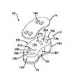
- FIG. 4Ais a perspective view of another embodiment of an artificial disc replacement implant having a circular configuration with radially-extending walls formed therein and adapted to buckle in response to movement of adjacent vertebrae;
- FIG. 4Bis a side view of the implant of FIG. 4A disposed between adjacent vertebrae;
- FIG. 4Cis a top view of the implant of FIG. 4A positioned on a vertebral body;
- FIG. 4Dis a cross-sectional view of the implant of FIG. 4A , showing a portion of the implant in a buckled position;
- FIG. 5is a top view of two of the implants of FIG. 4A positioned on a vertebral body;
- FIG. 6is a side view of yet another embodiment of an artificial disc replacement implant having superior and inferior walls adapted to buckle in response to movement of adjacent vertebrae;
- FIG. 7is a side view of yet another embodiment of an artificial disc replacement implant having a wall that extend radially outward from a center portion of the implant, showing the implant positioned between adjacent vertebrae.
- the present inventiongenerally provides devices and methods for replacing a spinal disc, and in particular devices and methods that rely on buckling to control movement of adjacent vertebrae.
- Bucklingrefers to the displacement mode characterized by a sudden large displacement of a structural member that is subjected to compressive stresses where the actual compressive stresses at failure are greater than the ultimate compressive stresses, i.e., the buckling strength, that the structure is capable of withstanding.
- an artificial disc replacement implantis provided and it includes at least one structural member that is adapted to buckle in response to movement of the adjacent vertebrae. When the implant is disposed between adjacent vertebrae, the structural member(s) will provide resistance to movement of the adjacent vertebrae.
- the structural member(s)When the forces applied to the structural member(s) are greater than the buckling strength of the structural member(s), the structural member(s) will buckle and collapse. In the collapsed configuration, the resistance to movement applied to the adjacent vertebrae by the implant is significantly decreased. The structural member(s) can, however, easily “bounce back” or return to the unbuckled configuration to once again provide a desired amount of resistance to movement.
- an implantcan be specifically configured to have desired buckling properties based on the intended use.
- an implantcan be configured to have structural members or walls, also referred to herein as columns, positioned at predetermined locations that will buckle when a predetermined load is applied thereto to thereby control particular types of movement between two adjacent vertebrae.
- Kis 1; where both ends of the column are fixed, K is 4; where one end of the column is fixed and the other end is free, K is 2; and where one end of the column is fixed and the other end is free to move laterally, K is 1 ⁇ 4.
- the buckling strength of a structural member configured to control movement between adjacent vertebraecan vary, by way of non-limiting example an implant can be configured having one or more structural members that have a buckling strength that corresponds to about 1 newton meter of moment induced on a spinal segment. This desired buckling strength can be used to determine the necessary configuration of each column in the implant.
- the particular configuration, location, and quantity of structural memberscan vary to control particular types of movement, such as flexion, extension, and lateral bending.
- the buckling strength of each structural membercan also be adapted to provide a desired amount of resistance to movement of the adjacent vertebrae.
- the implantincludes at least one wall that is adapted to buckle when a force is applied thereto that is greater than a buckling strength of the wall.
- the wallcan be defined by the shape and configuration of the implant body.
- the bodycan include one or more holes or openings formed therein that define a wall adjacent to the opening.
- the location of each wallcan also correspond to the desired movement to be controlled.
- the implantcan include posterior and anterior walls that are positioned in posterior and anterior regions of a disc space to control flexion and extension.
- the implantcan also or alternatively include lateral walls that are positioned in lateral regions of a disc space to control lateral bending.
- the structural member(s)can also have fixed ends to increase the buckling strength, or they can have free ends to reduce the buckling strength.
- the materials used to form the implantcan also function to cause the structural member(s) of the implant to buckle.
- various portions of the implantcan be formed from materials have properties, such as elasticity and/or stiffness, that differ from the properties of other portions of the implant.
- a person skilled in the artwill appreciate that a variety of techniques can be used to provide an implant having one or more structural members that buckle to control movement between adjacent vertebrae.
- FIGS. 1A-7illustrate various exemplary embodiments of implants having one or more structural members that are adapted to buckle to control movement between adjacent vertebrae.
- the particular configuration of the implant, as well as the configuration of each structural member,can vary depending on the desired movement to be controlled and the desired buckling properties.
- FIGS. 1A-1Billustrate one embodiment of an implant 10 that is adapted to be positioned between opposed endplates of adjacent vertebral bodies.
- the illustrated implant 10has a generally elongate body 12 with opposed superior and inferior surfaces 12 s , 12 i that are adapted to be positioned between superior and inferior endplates of adjacent vertebrae.
- the shape of the body 12can vary, but in the illustrated embodiment the body 12 has a shape that is configured to occupy a lateral portion of a disc space, rather than occupying the entire disc space.
- the elongate body 12has a slightly curved or C-shaped configuration such that the body 12 includes opposed anterior and posterior ends 12 a , 12 b and opposed first and second lateral sides 12 c , 12 d extending between the anterior and posterior ends 12 a , 12 b .
- the particular dimensions of the implant 10can also vary, but preferably the implant 10 has a height measured between the superior and inferior surfaces 12 s , 12 i that allows the implant 10 to function as a load-bearing element during movement of the adjacent vertebrae. In other words, the height is preferably sufficient to span across the disc space and contact the opposed endplates of the adjacent vertebrae.
- the implant 10can also optionally include first and second endplate members 14 , 16 adapted to mate to or be positioned adjacent to the superior and inferior surfaces 12 s , 12 i of the body 12 .
- Each endplate member 14 , 16can have various shapes and sizes, but in an exemplary embodiment each endplate member 14 , 16 can have a shape that corresponds to a shape of the body 12 .
- Each endplate member 14 , 16can also optionally include features to engage bone, such as one or more surface features, such as teeth 14 s , formed thereon.
- the body 12can be merely positioned between the endplate members 14 , 16 , or it can be mated to the endplate members 14 , 16 using various techniques known in the art, such as adhesives or other mechanical or chemical mating techniques.
- the endplate members 14 , 16can be positioned adjacent to the superior and inferior endplates of adjacent vertebrae to help prevent movement or expulsion of the implant 10 from the disc space.
- the body 12can also include one or more structural members adapted to buckle when a predetermined load is applied thereto.
- the anterior and posterior ends 12 a , 12 b of the body 12each include a pair of walls 18 a , 20 a , 18 b , 20 b , respectively, that extend between the superior and inferior surfaces 12 s , 12 i .
- each end 12 a , 12 bincludes an outer wall 18 a , 18 b and an adjacent inner wall 20 a , 20 b .
- the walls 18 a , 20 a , 18 b , 20 bare formed or defined by bores or openings extending through the body 12 between the superior and inferior surfaces 12 s , 12 i .
- the anterior end 12 a of the body 12has a first opening 19 a formed between the outer wall 18 a and the inner wall 20 a , and a second opening 21 a formed adjacent to the inner wall 20 a on a side opposite the first opening 19 a .
- the inner wall 20 ais defined by the first and second openings 19 a , 21 a .
- the posterior end 12 b of the body 12likewise has a first opening 19 b formed between the outer wall 18 b and the inner wall 20 b , and a second opening 21 b formed adjacent to the inner wall 20 b on a side opposite the first opening 19 b .
- the inner wall 20 bis defined by the first and second openings 19 b , 21 b .
- each opening 19 a , 21 a , 19 b , 21 bcan define the shape of each wall 18 a , 20 a , 18 b , 20 b .
- each opening 19 a , 21 a , 19 b , 21 bis in the form of an elongate, partially curved or C-shaped slot extending between the opposed sides 12 c , 12 d of the body 12 , i.e., in a direction substantially parallel to the anterior and posterior ends 12 a , 12 b .
- the openings 19 a , 21 a , 19 b , 21 balso extend through the body 12 between the superior and inferior surfaces 12 s , 12 i .
- each wall 18 a , 20 a , 28 b , 20 bhas a generally elongate, partially curved or C-shaped configuration.
- the walls 18 a , 20 a , 18 b , 20 bare curved in the direction of motion, as will be discussed in more detail below.
- the particular radius of the curvaturecan vary to obtain the desired buckling strength, but in an exemplary embodiment the walls 18 a , 20 a , 18 b , 20 b have only a slight curvature so as to increase the buckling strength of each wall.
- the size of each wall 18 a , 20 a , 18 b , 20 bcan also vary to obtain the desired buckling strength.
- walls 18 a , 20 a , 18 b , 20 b with a small width or thicknesswill decrease the buckling strength
- walls 18 a , 20 a , 18 b , 20 b with a greater width or thicknesswill increase the buckling strength of the wall.
- FIG. 1Billustrates the implant 10 of FIG. 1A in use.
- two implants 10 , 10 ′ having a configuration as described above with respect to FIG. 1Acan be positioned between adjacent vertebrae.
- One of the implants 10can be positioned on a first lateral side of a disc space, and the other implant 10 ′ can be positioned on an opposed lateral side of the disc space.
- the implants 10 , 10 ′can be oriented such that the anterior end 12 a , 12 a ′, of each implant 10 , 10 ′ is positioned adjacent to an anterior side of the disc space, and the opposed posterior end 12 b , 12 b ′ is positioned adjacent to a posterior side of the disc space.
- each implant 10 , 10 ′will be positioned in the anterior side of the disc space
- the walls (not shown) located on the posterior end 12 b , 12 b ′ of the implant 10 , 10 ′will be positioned in the posterior side of the disc space.
- the walls located on the anterior side of the disc spacewill be compressed and thus will provide resistance to flexion.
- the wallswill buckle, i.e., collapse.
- the implants 10 , 10 ′provide posterior and anterior buckling to accommodate flexion and extension of adjacent vertebrae.
- the portion located between the second openings (not shown) in each implant 10 , 10 ′can also be effective to provide resistance to vertical loading, as this portion will generally be positioned along the vertical axis of the spine.
- the outer walls 18 a , 18 b( FIG. 1A ) will likely buckle prior to the inner walls 20 a , 20 b .
- the wallscan, however, be configured to have differing buckling strengths to achieve a desired result. This can be achieved by altering the geometry of each wall. Preferably, however, the walls are curved in the direction of movement. In this embodiment, where the implant 10 is configured to control flexion and extension, movement will occur at the anterior and posterior ends 12 a , 12 b of the implant 10 . Thus, the walls can be curved outward toward the adjacent anterior and posterior ends 12 a , 12 b .
- the curvatureis very slight so as to still provide a sufficient buckling strength, as a greater curvature would reduce the buckling strength.
- the buckling strengthcan also be optimized by altering the material properties of the walls, for example by increasing or decreasing the thickness of each wall, or forming each wall from a different material, etc.
- FIGS. 2A-2Billustrate another embodiment of an implant 100 that is adapted to be positioned between opposed endplates of adjacent vertebral bodies, and that relies on buckling to control various movements between the adjacent vertebrae.
- the implant 100is similar to implant 10 described above, and generally includes an elongate, slightly curved or C-shaped body 112 having superior and inferior surfaces 112 s , 112 i , anterior and posterior ends 112 a , 112 b , and opposed sides 112 c , 112 d .
- the implant 100also includes opposed endplate members 114 , 116 that are positioned adjacent to the superior and inferior surfaces 112 s , 112 i , and that are adapted to engage the endplates of adjacent vertebrae when the implant 100 is implanted. While implant 100 is similar to implant 10 , in this embodiment the structural members are configured to provide lateral buckling to accommodate lateral bending.
- the body 112includes first and second laterally-extending openings 116 , 118 formed therein and extending between the anterior and posterior ends 112 a , 112 b thereof.
- the openings 116 , 118define first, second, and third laterally-extending walls 120 , 122 , 124 .
- the second wall 112is positioned between the first and third wall 120 , 124 , and thus extends along a mid-portion of the implant 100 .
- each wall 120 , 122 , 124can have a slightly curved configuration.
- the wallscan, however, have a straight configuration or have any other shape to achieve the desired buckling effect.
- FIG. 2Billustrates the implant 100 in use.
- two implants 100 , 100 ′ having a configuration as described above with respect to FIG. 2Acan be positioned between adjacent vertebrae.
- One of the implants 100can be positioned on a first lateral side of a disc space, and the other implant 100 ′ can be positioned on an opposed lateral side of the disc space.
- the implants 100 , 100 ′can be oriented such that the anterior end 112 a , 112 a ′, of each implant 100 , 100 ′ is positioned adjacent to an anterior side of the disc space, and the opposed posterior end 112 b , 112 b ′ is positioned adjacent to a posterior side of the disc space.
- the walls 120 , 122 , 124 , 120 ′, 122 ′, 124 ′will be positioned adjacent to the lateral sides of the disc space and will extend in a posterior-anterior direction.
- the wallswill be compressed and thus will provide resistance to lateral bending.
- the implant 100 positioned in the right lateral side of the disc spacewill provide resistance as the distance between the right lateral side of each vertebra decreases.
- Wall 120When the force applied to the walls by the vertebrae is greater than the buckling strength of the walls, the walls will buckle, i.e., collapse. Wall 120 will likely buckle before wall 122 , and wall 122 will likely buckle before wall 124 due to the positioning of the walls and the amount of force applied thereto during lateral bending. Walls 122 and 124 may also not buckle depending on the amount of lateral bending, and the particular properties of the implant 100 .
- FIGS. 3A and 3Billustrate yet another embodiment of an implant 300 that is adapted to be positioned between opposed endplates of adjacent vertebral bodies, and that relies on buckling to control various movements between the adjacent vertebrae. While two implants 300 , 300 ′ are shown, each implant can have the same or similar configuration and thus only one implant will be described.
- the implant 300generally includes a semi-circular shaped body 312 having superior and inferior surfaces 312 s , 312 i ( FIG. 3B ), anterior and posterior ends 312 a , 312 b , and a substantially planar side 312 c and an opposed curved side 312 d .
- the implant 300can also optionally include opposed endplate members that are positioned adjacent to the superior and inferior surfaces 312 s , 312 i , and that are adapted to engage the endplates of adjacent vertebrae when the implant 300 is implanted.
- the body 312can include one or more structural members that are configured to provide lateral buckling and posterior-anterior buckling.
- the body 312can include several openings formed therein and spaced radially around the body 312 .
- the body 312includes a first opening 314 positioned adjacent to the anterior end 312 a of the body 312 , a second opening 316 positioned the curved side 312 d of the body, and a third opening 318 positioned adjacent to the posterior end 312 b of the body 312 .
- each opening 314 , 316 , 318can vary, in an exemplary embodiment the openings 314 , 316 , 318 have a somewhat triangular or trapezoidal configuration.
- the body 312includes multiple structural members that can buckle when a force is applied thereto that is greater than a buckling strength of the member.
- the first opening 314can be surrounded by three walls 320 , 322 , 324 that could potentially buckle.
- a portion of the planar side 312 c adjacent to the first opening 314can form the first wall 320
- a portion of the curved side 312 d adjacent to the first opening 314can form the second wall 322
- a third wall 324can be formed between the first and second openings 314 , 316 .
- a portion of the curved side 312 d adjacent to the second opening 316can form a fourth wall 326
- a fifth wall 328can be formed between the second and third openings 316 , 318 .
- a portion of the curved side 312 d adjacent to the third opening 318can form a sixth wall 330
- a portion of the planar side 312 c adjacent to the third opening 318can form an eighth wall 332 .
- two implants 300 , 300 ′ having a similar configurationcan be positioned between adjacent vertebrae.
- One of the implants 300can be positioned on a first lateral side of a disc space, and the other implant 300 ′ can be positioned on an opposed lateral side of the disc space.
- the implants 300 , 300 ′can be oriented such that the anterior end 312 a , 312 a ′, of each implant 300 , 300 ′ is positioned adjacent to an anterior side of the disc space, and the opposed posterior end 312 b , 312 b ′ is positioned adjacent to a posterior side of the disc space.
- walls 320 and 332will extend in a posterior-anterior direction, while walls 322 , 326 , and 330 will extend adjacent to the lateral edge of the disc space.
- the walls 324 , 328 located between the openings 314 , 316 , 318will extend in a generally lateral direction.
- certain wallsmay buckle while others do not depending on the particular location of the wall as well as the particular configuration of each wall.
- one or more of the walls 322 , 326 , 330 located on the curved side 312 d of the body 312may buckle when a force is applied thereto that is greater than the buckling strength of the wall.
- walls 324 and 328can also buckle if a sufficient force is applied thereto.
- walls 330 and 322can buckle, as well as walls 320 and 332 .
- the core or central portion 334 of the body 312can provide resistance to vertical loading.
- FIGS. 4A-4Dillustrate yet another embodiment of an implant having buckling structures for controlling movement between adjacent vertebrae.
- the implant 400has a generally cylindrical shape with an outer wall 402 extending around a perimeter thereof, and several radial walls 406 a - g extending between a central core 404 and the outer wall 402 .
- the central core 404can provide resistance to vertical loading, while the outer wall 402 and the radial walls 406 a - g can provide resistance to lateral bending, flexion, and extension of the adjacent vertebrae.
- FIGS. 4B and 4Cillustrate the implant 400 in use, and as shown the implant 400 can have a shape and size that matches the shape and size of the endplate of a vertebra.
- the implant 400can have a diameter d that is adapted to span across the disc space, and a height h that is adapted to span between the endplates of the adjacent vertebrae.
- the central core 404will thus be aligned with a longitudinal axis of the spine to provide resistance to vertical loading, and the radial walls 406 a - g will extend radially from the central core 404 to provide buckling resistance to lateral bending, flexion, and extension.
- FIG. 4Dillustrates a cross-section of the implant 400 in a buckled state.
- a portion of the outer wall 402 , as well as one of the radial walls, e.g., wall 406 ahas collapsed or buckled in response to a force applied thereto.
- the walls 402 , 406 awill spring back to the unbuckled configuration, shown in FIGS. 4A-4C .
- implant 400is shown having a size and shape configured to match the size and shape of an endplate of a vertebrae, the implant 400 can have size and shape that allows the implant 400 to occupy only one lateral side of a disc space. This is illustrated, for example, in FIG. 5 which shows two implants 400 ′, 400 ′′ positioned on opposed lateral sides of a disc space. Each implant 400 ′, 400 ′′ will thus provide buckling resistance to various movements between the adjacent vertebrae.
- FIG. 6illustrates yet another embodiment of an implant 600 that is adapted to be positioned between opposed endplates of adjacent vertebral bodies, and that relies on buckling to control various movements between the adjacent vertebrae.
- the implant 600includes superior and inferior portions 602 , 604 , each having various structural members that are adapted to buckle when a predetermined force is applied thereto.
- the superior portion 602includes a superior endplate member 606 adapted to be positioned adjacent to an endplate of a superior vertebrae
- the inferior portion 604includes an inferior endplate member 608 adapted to be positioned adjacent to an endplate of an inferior vertebra.
- a middle plate member 610is disposed between the superior and inferior portions 602 , 604 .
- Each plate member 606 , 608 , 610can have various configurations, and they can be solid or have a circular shape with one or more openings formed therein.
- the plate members 606 , 608 , 610can also be substantially rigid or they can be flexible.
- the superior portion 602can include several structural members or walls 612 that extend between endplate member 606 and plate member 610
- the inferior portion 604can include several structural members or walls 614 that extend between endplate member 608 and plate member 610 .
- the walls 612 , 614can be configured to buckle when a force is applied thereto that is greater than a buckling strength of the wall. The particular location of each wall within the disc space, as well as the particular buckling strength of each wall, will determine which wall buckles in response to certain movements between the adjacent vertebrae.
- FIG. 7illustrates yet another embodiment of an implant 700 that is adapted to be positioned between opposed endplates of adjacent vertebral bodies, and that relies on buckling to control various movements between the adjacent vertebrae.
- the implant 700has a central core 702 which several structural members or inner walls 704 that extend radially outward from the central core 702 in various directions.
- Each inner wall 704has a generally curved configuration and extends outward and toward a superior or inferior endplate member 706 , 708 .
- the implant 700can also include an outer wall 710 extending around a perimeter thereof and extending between the superior and inferior endplate members 706 , 708 .
- the inner walls 704can provide resistance to vertical load placed on the implant 700 , and the outer wall 702 can be configured to buckle in response to movement between the adjacent vertebrae. Depending on the range of movement, the inner walls 704 could also be configured to buckle.
Landscapes
- Health & Medical Sciences (AREA)
- Engineering & Computer Science (AREA)
- Biomedical Technology (AREA)
- Neurology (AREA)
- Orthopedic Medicine & Surgery (AREA)
- Cardiology (AREA)
- Oral & Maxillofacial Surgery (AREA)
- Transplantation (AREA)
- Heart & Thoracic Surgery (AREA)
- Vascular Medicine (AREA)
- Life Sciences & Earth Sciences (AREA)
- Animal Behavior & Ethology (AREA)
- General Health & Medical Sciences (AREA)
- Public Health (AREA)
- Veterinary Medicine (AREA)
- Prostheses (AREA)
Abstract
Description
F=(Kπ2EI)/I2
where F is the maximum or critical force, E is the modulus of elasticity, I is the area moment of inertia, l is the unsupported length of the column, and K is a constant whose value depends upon the conditions of the end support of the columns. Where both ends of the column are free, K is 1; where both ends of the column are fixed, K is 4; where one end of the column is fixed and the other end is free, K is 2; and where one end of the column is fixed and the other end is free to move laterally, K is ¼. While the buckling strength of a structural member configured to control movement between adjacent vertebrae can vary, by way of non-limiting example an implant can be configured having one or more structural members that have a buckling strength that corresponds to about 1 newton meter of moment induced on a spinal segment. This desired buckling strength can be used to determine the necessary configuration of each column in the implant.
Claims (12)
Priority Applications (2)
| Application Number | Priority Date | Filing Date | Title |
|---|---|---|---|
| US11/610,796US8715352B2 (en) | 2006-12-14 | 2006-12-14 | Buckling disc replacement |
| PCT/US2007/023411WO2008076181A2 (en) | 2006-12-14 | 2007-11-07 | Buckling disc replacement |
Applications Claiming Priority (1)
| Application Number | Priority Date | Filing Date | Title |
|---|---|---|---|
| US11/610,796US8715352B2 (en) | 2006-12-14 | 2006-12-14 | Buckling disc replacement |
Publications (2)
| Publication Number | Publication Date |
|---|---|
| US20080147191A1 US20080147191A1 (en) | 2008-06-19 |
| US8715352B2true US8715352B2 (en) | 2014-05-06 |
Family
ID=39528486
Family Applications (1)
| Application Number | Title | Priority Date | Filing Date |
|---|---|---|---|
| US11/610,796Active2029-07-24US8715352B2 (en) | 2006-12-14 | 2006-12-14 | Buckling disc replacement |
Country Status (2)
| Country | Link |
|---|---|
| US (1) | US8715352B2 (en) |
| WO (1) | WO2008076181A2 (en) |
Families Citing this family (26)
| Publication number | Priority date | Publication date | Assignee | Title |
|---|---|---|---|---|
| US8088163B1 (en) | 2008-02-06 | 2012-01-03 | Kleiner Jeffrey B | Tools and methods for spinal fusion |
| US20210378834A1 (en) | 2008-05-22 | 2021-12-09 | Spinal Surgical Strategies, Inc., A Nevada Corporation D/B/A Kleiner Device Labs | Spinal fusion cage system with inserter |
| KR20110049771A (en)* | 2008-07-14 | 2011-05-12 | 신세스 게엠바하 | Flexible buffering intervertebral spacer device |
| USD853560S1 (en) | 2008-10-09 | 2019-07-09 | Nuvasive, Inc. | Spinal implant insertion device |
| US8147554B2 (en)* | 2008-10-13 | 2012-04-03 | Globus Medical, Inc. | Intervertebral spacer |
| US8366748B2 (en) | 2008-12-05 | 2013-02-05 | Kleiner Jeffrey | Apparatus and method of spinal implant and fusion |
| US9717403B2 (en) | 2008-12-05 | 2017-08-01 | Jeffrey B. Kleiner | Method and apparatus for performing retro peritoneal dissection |
| US8864654B2 (en) | 2010-04-20 | 2014-10-21 | Jeffrey B. Kleiner | Method and apparatus for performing retro peritoneal dissection |
| USD656610S1 (en) | 2009-02-06 | 2012-03-27 | Kleiner Jeffrey B | Spinal distraction instrument |
| US9247943B1 (en) | 2009-02-06 | 2016-02-02 | Kleiner Intellectual Property, Llc | Devices and methods for preparing an intervertebral workspace |
| US8419739B2 (en) | 2009-08-24 | 2013-04-16 | Amir A. Jamali | Method and apparatus for allograft disc transplantation |
| US8906028B2 (en) | 2009-09-18 | 2014-12-09 | Spinal Surgical Strategies, Llc | Bone graft delivery device and method of using the same |
| US10973656B2 (en) | 2009-09-18 | 2021-04-13 | Spinal Surgical Strategies, Inc. | Bone graft delivery system and method for using same |
| US9060877B2 (en) | 2009-09-18 | 2015-06-23 | Spinal Surgical Strategies, Llc | Fusion cage with combined biological delivery system |
| US9173694B2 (en) | 2009-09-18 | 2015-11-03 | Spinal Surgical Strategies, Llc | Fusion cage with combined biological delivery system |
| USD723682S1 (en) | 2013-05-03 | 2015-03-03 | Spinal Surgical Strategies, Llc | Bone graft delivery tool |
| US8685031B2 (en) | 2009-09-18 | 2014-04-01 | Spinal Surgical Strategies, Llc | Bone graft delivery system |
| US10245159B1 (en) | 2009-09-18 | 2019-04-02 | Spinal Surgical Strategies, Llc | Bone graft delivery system and method for using same |
| US9186193B2 (en) | 2009-09-18 | 2015-11-17 | Spinal Surgical Strategies, Llc | Fusion cage with combined biological delivery system |
| USD750249S1 (en) | 2014-10-20 | 2016-02-23 | Spinal Surgical Strategies, Llc | Expandable fusion cage |
| US9629729B2 (en) | 2009-09-18 | 2017-04-25 | Spinal Surgical Strategies, Llc | Biological delivery system with adaptable fusion cage interface |
| US20170238984A1 (en) | 2009-09-18 | 2017-08-24 | Spinal Surgical Strategies, Llc | Bone graft delivery device with positioning handle |
| FR2981262B1 (en)* | 2011-10-14 | 2014-09-19 | Pierre Roussouly | INTERSOMATIC IMPLANT |
| US20130261746A1 (en)* | 2012-03-28 | 2013-10-03 | Linares Medical Devices, Llc | Implantable inter-vertebral disk having upper and lower layers of a metal exhibiting bone fusing characteristics and which sandwich therebetween a soft plastic cushioning disc for providing dynamic properties mimicking that of a natural inter-vertebral disc |
| USD797290S1 (en) | 2015-10-19 | 2017-09-12 | Spinal Surgical Strategies, Llc | Bone graft delivery tool |
| CN110074900B (en) | 2019-02-01 | 2024-04-02 | 北京爱康宜诚医疗器材有限公司 | Joint spacer prosthesis and joint prosthesis with same |
Citations (187)
| Publication number | Priority date | Publication date | Assignee | Title |
|---|---|---|---|---|
| US3007834A (en)* | 1960-06-17 | 1961-11-07 | Dow Chemical Co | Honeycomb fabrication |
| US3867728A (en)* | 1971-12-30 | 1975-02-25 | Cutter Lab | Prosthesis for spinal repair |
| US4349921A (en)* | 1980-06-13 | 1982-09-21 | Kuntz J David | Intervertebral disc prosthesis |
| US4772287A (en) | 1987-08-20 | 1988-09-20 | Cedar Surgical, Inc. | Prosthetic disc and method of implanting |
| US4880429A (en)* | 1987-07-20 | 1989-11-14 | Stone Kevin R | Prosthetic meniscus |
| US4911718A (en)* | 1988-06-10 | 1990-03-27 | University Of Medicine & Dentistry Of N.J. | Functional and biocompatible intervertebral disc spacer |
| US5171281A (en)* | 1988-08-18 | 1992-12-15 | University Of Medicine & Dentistry Of New Jersey | Functional and biocompatible intervertebral disc spacer containing elastomeric material of varying hardness |
| US5562738A (en) | 1992-01-06 | 1996-10-08 | Danek Medical, Inc. | Intervertebral disk arthroplasty device |
| US5702450A (en) | 1993-06-28 | 1997-12-30 | Bisserie; Michel | Intervertebral disk prosthesis |
| US5716416A (en) | 1996-09-10 | 1998-02-10 | Lin; Chih-I | Artificial intervertebral disk and method for implanting the same |
| US5928284A (en) | 1998-07-09 | 1999-07-27 | Mehdizadeh; Hamid M. | Disc replacement prosthesis |
| US6086595A (en) | 1997-08-29 | 2000-07-11 | Sulzer Spine-Tech Inc. | Apparatus and method for spinal stabilization |
| US6146419A (en)* | 1999-05-13 | 2000-11-14 | Board Of Trustees Of The University | Method for forming a hollow prosthesis |
| US6179874B1 (en) | 1998-04-23 | 2001-01-30 | Cauthen Research Group, Inc. | Articulating spinal implant |
| US6231609B1 (en) | 1998-07-09 | 2001-05-15 | Hamid M. Mehdizadeh | Disc replacement prosthesis |
| US6440168B1 (en) | 1998-04-23 | 2002-08-27 | Sdgi Holdings, Inc. | Articulating spinal implant |
| US20020188300A1 (en) | 2001-06-06 | 2002-12-12 | Arramon Yves P. | Cannula system for hard tissue implant delivery |
| US20030023312A1 (en)* | 2000-08-15 | 2003-01-30 | Thalgott John S. | Disc prosthesis |
| US6530956B1 (en)* | 1998-09-10 | 2003-03-11 | Kevin A. Mansmann | Resorbable scaffolds to promote cartilage regeneration |
| US20030055427A1 (en) | 1999-12-01 | 2003-03-20 | Henry Graf | Intervertebral stabilising device |
| US6572653B1 (en) | 2001-12-07 | 2003-06-03 | Rush E. Simonson | Vertebral implant adapted for posterior insertion |
| US6610093B1 (en) | 2000-07-28 | 2003-08-26 | Perumala Corporation | Method and apparatus for stabilizing adjacent vertebrae |
| US20030199982A1 (en) | 1998-09-04 | 2003-10-23 | Sdgi Holdings, Inc. | Peanut spectacle multi discoid thoraco-lumbar disc prosthesis |
| US20030220643A1 (en) | 2002-05-24 | 2003-11-27 | Ferree Bret A. | Devices to prevent spinal extension |
| US6679915B1 (en) | 1998-04-23 | 2004-01-20 | Sdgi Holdings, Inc. | Articulating spinal implant |
| US6692495B1 (en) | 1999-10-14 | 2004-02-17 | Fred Zacouto | Vertebral fixator and articulation |
| WO2004019828A1 (en) | 2002-09-02 | 2004-03-11 | Mathys Medizinaltechnik Ag | Intervertebral implant comprising a three-part articulation |
| WO2004019830A1 (en) | 2002-08-28 | 2004-03-11 | Diamicron, Inc. | Articulating diamond-surfaced spinal implants |
| WO2004026187A1 (en) | 2002-09-19 | 2004-04-01 | Malan De Villiers | Intervertebral prosthesis |
| WO2004026186A1 (en) | 2002-09-18 | 2004-04-01 | Mathys Medizinaltechnik Ag | Implant comprising a two-piece joint |
| WO2004028415A1 (en) | 2002-09-26 | 2004-04-08 | Spinecore, Inc. | Artificial intervertebral disc having a captured ball and socket joint |
| WO2004033516A1 (en) | 2002-10-08 | 2004-04-22 | Ranier Limited | High precision manufacture of polyurethane products such as spinal disc implants having gradual modulus variation |
| WO2004047691A1 (en) | 2002-11-21 | 2004-06-10 | Sdgi Holdings, Inc. | Systems and techniques for interbody spinal stablization with expandable devices |
| WO2004049980A1 (en) | 2002-11-29 | 2004-06-17 | Dsm Ip Assets B.V. | Artificial intervertebral disc |
| US20040127992A1 (en)* | 2002-12-31 | 2004-07-01 | Serhan Hassan A. | Annular nucleus pulposus replacement |
| WO2004054480A1 (en) | 2002-12-13 | 2004-07-01 | Spine Solutions Inc. | Intervertebral implant, insertion tool and method of inserting same |
| WO2004054478A1 (en) | 2002-12-17 | 2004-07-01 | Mathys Medizinaltechnik Ag | Intervertebral implant |
| WO2004054477A1 (en) | 2002-12-17 | 2004-07-01 | Mathys Medizinaltechnik Ag | Intervertebral implant comprising joint parts that are mounted to form a universal joint |
| WO2004054479A1 (en) | 2002-12-17 | 2004-07-01 | Mathys Medizinaltechnik Ag | Intervertebral implant |
| US20040138753A1 (en) | 2003-01-07 | 2004-07-15 | Ferree Bret A. | Artificial disc replacements with articulating components |
| US20040138749A1 (en) | 2002-10-29 | 2004-07-15 | St. Francis Medical Technologies, Inc. | Artificial vertebral disk replacement implant with translating pivot point and method |
| US20040143270A1 (en) | 2002-10-29 | 2004-07-22 | St. Francis Medical Technologies, Inc. | Tools for implanting artificial vertebral disk and method |
| US20040153157A1 (en) | 2001-04-05 | 2004-08-05 | Arnold Keller | System for intervertebral disk prostheses |
| US20040158254A1 (en) | 2003-02-12 | 2004-08-12 | Sdgi Holdings, Inc. | Instrument and method for milling a path into bone |
| US20040167538A1 (en) | 2001-05-03 | 2004-08-26 | Synthes (U.S.A.) | Method of performing a transforaminal posterior lumbar interbody fusion procedure |
| WO2004073561A1 (en) | 2003-02-13 | 2004-09-02 | Spinevision | Intervertebral prosthesis |
| US20040181285A1 (en) | 2001-12-07 | 2004-09-16 | Simonson Rush E. | Vertebral implants adapted for posterior insertion |
| US20040181284A1 (en) | 2001-12-07 | 2004-09-16 | Simonson Rush E. | Vertebral implant with dampening matrix adapted for posterior insertion |
| US20040186577A1 (en) | 2003-01-29 | 2004-09-23 | Ferree Bret A. | In situ artificaial disc replacements and other prosthetic components |
| US6814737B2 (en) | 1999-10-20 | 2004-11-09 | Cauthen Research Group, Inc. | Spinal implant insertion instrument for spinal interbody prostheses |
| US20040225364A1 (en) | 2003-05-06 | 2004-11-11 | Marc Richelsoph | Artificial intervertebral disc |
| US20040225362A1 (en) | 2003-05-06 | 2004-11-11 | Marc Richelsoph | Artificial intervertebral disc |
| WO2004098465A1 (en) | 2003-05-02 | 2004-11-18 | Medicinelodge, Inc. | Method and apparatus for spine joint replacement |
| US20040226098A1 (en)* | 1996-02-14 | 2004-11-18 | Pearce Tony M. | Stacked cushions |
| US20040254644A1 (en) | 2002-10-21 | 2004-12-16 | Taylor Brett Allison | Intervertebral disk prosthesis |
| US20040267369A1 (en) | 2002-04-25 | 2004-12-30 | Matthew Lyons | Artificial intervertebral disc |
| US20050015150A1 (en) | 2003-07-17 | 2005-01-20 | Lee Casey K. | Intervertebral disk and nucleus prosthesis |
| US20050033432A1 (en) | 2003-08-05 | 2005-02-10 | Charles Gordon | Artificial spinal unit assemblies |
| US20050033435A1 (en) | 2003-08-04 | 2005-02-10 | Spine Next | Intervertebral disk prosthesis |
| US20050033437A1 (en) | 2002-05-23 | 2005-02-10 | Pioneer Laboratories, Inc. | Artificial disc device |
| US20050033431A1 (en) | 2003-08-05 | 2005-02-10 | Charles Gordon | Artificial functional spinal unit assemblies |
| US20050033439A1 (en) | 2003-08-05 | 2005-02-10 | Charles Gordon | Artificial functional spinal unit assemblies |
| US20050038516A1 (en) | 2003-08-14 | 2005-02-17 | Mark Spoonamore | Intervertebral disk prosthesis and method |
| US20050038515A1 (en) | 2003-06-20 | 2005-02-17 | Sdgi Holdings, Inc. | Lumbar composite nucleus |
| US20050038445A1 (en) | 2001-07-16 | 2005-02-17 | Errico Joseph P. | Instrumentation for repositioning and extracting an artificial intervertebral disc from an intervertebral space |
| US20050043803A1 (en) | 2003-08-22 | 2005-02-24 | Robert Schultz | Intervertebral implant |
| US20050043801A1 (en) | 2003-08-21 | 2005-02-24 | Trieu Hai H. | Allogenic/xenogenic implants and methods for augmenting or repairing intervertebral discs |
| US20050043800A1 (en) | 2003-07-31 | 2005-02-24 | Paul David C. | Prosthetic spinal disc replacement |
| US20050043740A1 (en) | 2003-08-20 | 2005-02-24 | Haid Regis W. | Technique and instrumentation for preparation of vertebral members |
| US20050049590A1 (en) | 2003-03-07 | 2005-03-03 | Neville Alleyne | Spinal implant with securement spikes |
| US20050049623A1 (en) | 2003-09-02 | 2005-03-03 | Moore Jeffrey D. | Devices and techniques for a minimally invasive disc space preparation and implant insertion |
| US20050049707A1 (en) | 2003-08-29 | 2005-03-03 | Ferree Bret A. | Cemented artificial disc replacements |
| US20050060035A1 (en) | 2001-07-16 | 2005-03-17 | Errico Joseph P. | Intervertebral spacer device having recessed notch pairs for manipulation using a surgical tool |
| US20050065610A1 (en) | 1994-03-18 | 2005-03-24 | Madhavan Pisharodi | Rotating, locking, spring-loaded artificial disk |
| US20050065611A1 (en) | 2001-11-06 | 2005-03-24 | Jean Huppert | Osseous achoring device for a prosthesis |
| WO2005033437A1 (en) | 2003-09-30 | 2005-04-14 | Walter Karl Stavenjord | Casing system |
| US6881228B2 (en) | 1999-06-04 | 2005-04-19 | Sdgi Holdings, Inc. | Artificial disc implant |
| US20050085909A1 (en) | 2003-10-15 | 2005-04-21 | Sdgi Holding, Inc. | Semi-constrained and mobile-bearing disc prosthesis |
| US20050085917A1 (en) | 1999-07-02 | 2005-04-21 | Thierry Marnay | Intervertebral implant |
| US20050085916A1 (en) | 2000-04-26 | 2005-04-21 | Li Lehmann K. | Apparatus and method for replacing the nucleus pulposus of an intervertebral disc or for replacing an entire intervertebral disc |
| WO2005037148A1 (en) | 2003-10-17 | 2005-04-28 | Scient'x | Lumbar disk prosthesis |
| US6887274B2 (en) | 2001-02-15 | 2005-05-03 | Spinecore, Inc. | Intervertebral spacer device utilizing a belleville washer having radially spaced concentric grooves |
| US6887273B2 (en) | 2001-10-18 | 2005-05-03 | Spinecore, Inc. | Intervertebral spacer device having a domed arch shaped spring |
| US20050096746A1 (en) | 2001-11-26 | 2005-05-05 | Sdgi Holdings, Inc. | Instrumentation and associated methods for joint prosthesis implantation |
| WO2005039455A1 (en) | 2003-09-23 | 2005-05-06 | Vanderbilt University | Intervertebral disc replacement prosthesis |
| US20050102029A1 (en) | 2003-10-28 | 2005-05-12 | Nu Vasive, Inc. | Total disc replacement system and related methods |
| US20050102030A1 (en) | 2000-10-24 | 2005-05-12 | Cryolife, Inc. | In situ bioprosthetic filler and methods, particularly for the in situ formation of vertebral disc bioprosthetics |
| US20050102027A1 (en) | 2003-11-12 | 2005-05-12 | Ferree Bret A. | Shims, particularly for laterally placed artificial disc replacements (ADRS) |
| US6893466B2 (en) | 2000-08-30 | 2005-05-17 | Sdgi Holdings, Inc. | Intervertebral disc nucleus implants and methods |
| US6893465B2 (en) | 2003-03-31 | 2005-05-17 | Shi, Tain-Yew | Vividly simulated prosthetic intervertebral disc |
| US20050107881A1 (en) | 2003-05-02 | 2005-05-19 | Neville Alleyne | Artificial spinal disk |
| US6896680B2 (en) | 2001-03-01 | 2005-05-24 | Gary K. Michelson | Arcuate dynamic lordotic guard with movable extensions for creating an implantation space posteriorly in the lumbar spine |
| US20050113926A1 (en) | 2003-11-21 | 2005-05-26 | St. Francis Medical Technologies, Inc. | Method of laterally inserting an artificial vertebral disk replacement implant with curved spacer |
| WO2005046534A1 (en) | 2003-10-29 | 2005-05-26 | Laurent Salle | Total intervertebral-disc prothesis |
| US20050113928A1 (en) | 2000-02-16 | 2005-05-26 | Cragg Andrew H. | Dual anchor prosthetic nucleus apparatus |
| US20050119747A1 (en)* | 2002-02-26 | 2005-06-02 | Sdgi Holdings, Inc. | Connectable interbody implant |
| JP2005137905A (en) | 2003-05-06 | 2005-06-02 | Spinal Innovations Inc | Artificial intervertebral disk |
| US20050119752A1 (en) | 2003-11-19 | 2005-06-02 | Synecor Llc | Artificial intervertebral disc |
| US20050119750A1 (en) | 2002-04-04 | 2005-06-02 | Marthys Medizinaltechnik Ag | Intervertebral prosthesis or nucleus replacement prosthesis |
| US20050119749A1 (en) | 2001-02-28 | 2005-06-02 | Lange Eric C. | Flexible spine stabilization systems |
| US20050125061A1 (en) | 2003-12-08 | 2005-06-09 | Zucherman James F. | System and method for replacing degenerated spinal disks |
| US20050125064A1 (en) | 2001-02-15 | 2005-06-09 | Spinecore, Inc. | Intervertebral spacer device |
| US20050125065A1 (en) | 2003-11-05 | 2005-06-09 | St. Francis Medical Technologies Inc. | Laterally insertable artificial vertebral disk replacement implant with crossbar spacer |
| US20050125062A1 (en) | 2003-12-09 | 2005-06-09 | Lutz Biedermann | Height-adjustable intervertebrae implant |
| US20050125063A1 (en) | 2002-03-15 | 2005-06-09 | Fixano | Dynamic intervertebral implant |
| US20050124992A1 (en) | 2002-04-24 | 2005-06-09 | Ferree Bret A. | Methods and apparatus for placing intradiscal devices |
| US20050130929A1 (en) | 2001-11-01 | 2005-06-16 | Boyd Lawrence M. | System and method for the pretreatment of the endplates of an intervertebral disc |
| US20050131543A1 (en) | 2003-12-10 | 2005-06-16 | Axiomed Spine Corporation | Method and apparatus for replacing a damaged spinal disc |
| US20050131536A1 (en) | 2003-12-11 | 2005-06-16 | Lukas Eisermann | Expandable intervertebral implant |
| WO2005053579A1 (en) | 2003-11-28 | 2005-06-16 | Gilles Voydeville | Postero-lateral intervertebral disc prosthesis |
| US20050131541A1 (en)* | 2000-08-30 | 2005-06-16 | Trieu Hai H. | Intervertebral disc nucleus implants and methods |
| WO2005053580A1 (en) | 2003-11-28 | 2005-06-16 | Richard Mervyn Walker | An intervertebral prosthesis |
| US20050143820A1 (en) | 2003-12-02 | 2005-06-30 | St. Francis Medical Technologies, Inc. | Method of laterally inserting an artificial vertebral disk replacement implant with translating pivot point |
| US20050143824A1 (en) | 2003-05-06 | 2005-06-30 | Marc Richelsoph | Artificial intervertebral disc |
| US20050149196A1 (en) | 2004-01-07 | 2005-07-07 | St. Francis Medical Technologies, Inc. | Artificial spinal disk replacement device with rotation limiter and lateral approach implantation method |
| US20050149188A1 (en) | 2002-02-07 | 2005-07-07 | Cook Stephen D. | Anterior spinal implant |
| US20050154468A1 (en) | 2004-01-13 | 2005-07-14 | Rivin Evgeny I. | Artificial intervertebral disc |
| US20050154461A1 (en) | 2004-01-09 | 2005-07-14 | Sdgi Holdings, Inc. | Dual articulating spinal device and method |
| US20050154466A1 (en) | 2004-01-09 | 2005-07-14 | Sdgi Holdings, Inc. | Posterior spinal device and method |
| US20050154467A1 (en) | 2004-01-09 | 2005-07-14 | Sdgi Holdings, Inc. | Interconnected spinal device and method |
| US20050154464A1 (en) | 2004-01-09 | 2005-07-14 | Sdgi Holdings, Inc. | Support structure device and method |
| WO2005063150A1 (en) | 2003-12-31 | 2005-07-14 | Henning Kloss | Intervertebral disc implant |
| US20050154465A1 (en) | 2004-01-09 | 2005-07-14 | Sdgi Holdings, Inc. | Split spinal device and method |
| US6918934B2 (en) | 2001-10-01 | 2005-07-19 | Spinecore, Inc. | Artificial intervertebral disc having a slotted belleville washer force restoring element |
| US20050159818A1 (en) | 2002-06-26 | 2005-07-21 | Jason Blain | Total disc replacement system and related methods |
| EP1555964A1 (en) | 2002-10-28 | 2005-07-27 | Mathys Medizinaltechnik AG | Intervertebral disk prosthesis or artificial vertebra |
| EP1342456B1 (en) | 1996-11-22 | 2005-07-27 | Glenn R. Buttermann | Intervertebral prosthetic device |
| US20050165486A1 (en) | 2004-01-27 | 2005-07-28 | Sdgi Holdings, Inc. | Prosthetic device and method |
| US20050165485A1 (en) | 2004-01-27 | 2005-07-28 | Sdgi Holdings, Inc. | Hybrid intervertebral disc system |
| US20050165484A1 (en) | 2004-01-22 | 2005-07-28 | Ferree Bret A. | Artificial disc replacement (ADR) fixation methods and apparatus |
| US20050165407A1 (en) | 2004-01-23 | 2005-07-28 | Diaz Robert L. | Disk arthroplasty instrumentation and implants |
| EP1273276B1 (en) | 2001-07-05 | 2005-08-03 | Fehling AG | Intervertebral disc prosthesis |
| WO2005070349A1 (en) | 2004-01-09 | 2005-08-04 | Sdgi Holdings, Inc. | Mobile bearing spinal device and method |
| US20050171611A1 (en) | 1999-09-30 | 2005-08-04 | Replication Medical, Inc. | Hydrogel-based prosthetic device for replacing at least a part of the nucleus of a spinal disc |
| US20050171609A1 (en) | 2004-01-09 | 2005-08-04 | Sdgi Holdings, Inc. | Spinal arthroplasty device and method |
| US20050171550A1 (en) | 2004-01-30 | 2005-08-04 | Sdgi Holdings, Inc. | Anatomic implants designed to minimize instruments and surgical techniques |
| US20050177239A1 (en) | 1995-09-04 | 2005-08-11 | Amiram Steinberg | Method and apparatus for computerized surgery |
| WO2005074839A1 (en) | 2004-02-04 | 2005-08-18 | Ldr Medical | Intervertebral disc prosthesis |
| US20050187631A1 (en) | 2004-01-27 | 2005-08-25 | Sdgi Holdings, Inc. | Prosthetic device |
| US20050187633A1 (en) | 2003-11-10 | 2005-08-25 | Ferree Bret A. | Modular artificial disc replacements (ADRS) that allow translocation and axial rotation |
| US20050187632A1 (en) | 2004-02-20 | 2005-08-25 | Rafail Zubok | Artificial intervertebral disc having a bored semispherical bearing with a compression locking post and retaining caps |
| US6936070B1 (en) | 2001-01-17 | 2005-08-30 | Nabil L. Muhanna | Intervertebral disc prosthesis and methods of implantation |
| US20050192674A1 (en) | 1999-10-08 | 2005-09-01 | Ferree Bret A. | Prosthetic joints with contained compressible resilient members |
| US20050192670A1 (en) | 2004-02-19 | 2005-09-01 | Spinecore, Inc. | Artificial intervertebral disc having an articulating joint |
| US20050197702A1 (en)* | 2002-08-15 | 2005-09-08 | Coppes Justin K. | Intervertebral disc implant |
| US20050197705A1 (en) | 2004-03-08 | 2005-09-08 | Uri Arnin | Spinal prosthesis |
| US20050203627A1 (en) | 2004-01-23 | 2005-09-15 | Corin Limited | Intervertebral disc prosthesis |
| US20050203626A1 (en) | 2004-03-15 | 2005-09-15 | Sdgi Holdings, Inc. | System and method for stabilizing a prosthetic device |
| US20050209696A1 (en) | 2004-01-16 | 2005-09-22 | Jo-Wen Lin | Implant frames for use with settable materials and related methods of use |
| US20050216084A1 (en) | 2003-04-22 | 2005-09-29 | Fleischmann Lewis W | Collapsible, rotatable, and tiltable hydraulic spinal disc prosthesis system with selectable modular components |
| US20050216086A1 (en) | 2004-03-23 | 2005-09-29 | Sdgi Holdings, Inc. | Constrained artificial spinal disc |
| US20050216092A1 (en) | 2004-03-23 | 2005-09-29 | Sdgi Holdings, Inc. | Constrained artificial implant for orthopaedic applications |
| US20050222683A1 (en) | 2004-03-31 | 2005-10-06 | Sdgi Holdings | Shape memory alloy disc replacement device |
| WO2005092247A1 (en) | 2004-03-26 | 2005-10-06 | Nuvasive Inc. | Prosthetic spinal disc |
| WO2005094734A1 (en) | 2004-03-30 | 2005-10-13 | Hjs Gelenk System Gmbh | Artificial intervertebral disk |
| US20050228497A1 (en) | 2002-04-23 | 2005-10-13 | Ferree Bret A | Artificial disc replacements with natural kinematics |
| US20050228500A1 (en) | 2003-08-01 | 2005-10-13 | Spinal Kinetics, Inc. | Prosthetic intervertebral disc and methods for using same |
| WO2005094732A1 (en) | 2004-04-02 | 2005-10-13 | Synthes Gmbh | Modular intervertebral implant or intervertebral disc prosthesis |
| WO2005094733A1 (en) | 2004-04-02 | 2005-10-13 | Synthes Gmbh | Intervertebral disc prosthesis or artificial vertebral body |
| US20050234553A1 (en) | 1999-05-17 | 2005-10-20 | Vanderbilt University | Intervertebral disc replacement prothesis |
| US20050234556A1 (en) | 2004-04-08 | 2005-10-20 | Peter Kretschmer | Intervertebral disk prosthesis |
| US6958078B2 (en)* | 2002-08-19 | 2005-10-25 | The University Of Toledo | Bioartificial intervertebral disc |
| US20050240273A1 (en) | 2002-12-17 | 2005-10-27 | Khandkar Ashock C | Total disc implant |
| US6960232B2 (en) | 2002-04-25 | 2005-11-01 | Blackstone Medical, Inc. | Artificial intervertebral disc |
| US20050246024A1 (en) | 2004-04-28 | 2005-11-03 | Ldr Medical, Inc. | Intervertebral disc prosthesis |
| US20050246022A1 (en) | 2004-02-20 | 2005-11-03 | Rafail Zubok | Artificial intervertebral disc having a universal joint |
| US20050251260A1 (en)* | 2002-08-15 | 2005-11-10 | David Gerber | Controlled artificial intervertebral disc implant |
| US20050251261A1 (en) | 2004-05-05 | 2005-11-10 | Sdgi Holdings, Inc. | Artificial intervertebral disc for lateral insertion |
| US20050256581A1 (en) | 2002-05-23 | 2005-11-17 | Pioneer Laboratories, Inc. | Artificial disc device |
| US20050256576A1 (en) | 2004-05-13 | 2005-11-17 | Moskowitz Nathan C | Artificial expansile total lumbar and thoracic discs for posterior placement without supplemental instrumentation and its adaptation for anterior placement of artificial cervical, thoracic and lumbar discs |
| US6966929B2 (en) | 2002-10-29 | 2005-11-22 | St. Francis Medical Technologies, Inc. | Artificial vertebral disk replacement implant with a spacer |
| US6966931B2 (en) | 2003-05-21 | 2005-11-22 | Tain-Yew Shi | Artificial intervertebral disc with reliable maneuverability |
| US20050261773A1 (en) | 2002-05-15 | 2005-11-24 | Ferree Bret A | Lateral-approach artificial disc replacements |
| US20050261772A1 (en) | 2004-05-18 | 2005-11-24 | Zimmer Gmbh | Intervertebral disk implant |
| US20050267580A1 (en) | 2003-04-23 | 2005-12-01 | Loubert Suddaby | Inflatable intervertebral disc replacement prosthesis |
| US20050267582A1 (en) | 2002-04-12 | 2005-12-01 | Spinecore, Inc. | Spacerless artificial disc replacements |
| US20060047341A1 (en)* | 2004-08-24 | 2006-03-02 | Trieu Hai H | Spinal disc implants with reservoirs for delivery of therapeutic agents |
| US7037340B2 (en) | 1999-08-03 | 2006-05-02 | Ldr Medical | Intervertebral nucleus prosthesis and surgical procedure for implanting the same |
| EP1532948B1 (en) | 2003-11-18 | 2006-06-21 | Zimmer GmbH | Surgical system for insertion of spinal disc prostheses |
| US7105025B2 (en)* | 1999-04-07 | 2006-09-12 | Howmedica Osteonics Corp. | Low profile fusion cage and insertion set |
| US20060247781A1 (en)* | 2005-04-29 | 2006-11-02 | Sdgi Holdings, Inc. | Implant |
| US20060259146A1 (en)* | 2003-04-04 | 2006-11-16 | Theken Disc, Llc | Artificial disc prosthesis |
| US20070233245A1 (en)* | 2006-03-31 | 2007-10-04 | Sdgi Holdings, Inc. | Methods and instruments for delivering intervertebral devices |
| EP1572036B1 (en) | 2002-12-17 | 2008-05-07 | Synthes GmbH | Intervertebral implant with joint parts mounted on roller bodies |
| EP1572037B1 (en) | 2002-12-17 | 2008-05-07 | Synthes GmbH | Intervertebral implant with tiltable joint parts |
| US20080140199A1 (en)* | 2004-07-21 | 2008-06-12 | Arne Briest | Impantable Body for Spinal Fusion |
| US8092533B2 (en)* | 2006-10-03 | 2012-01-10 | Warsaw Orthopedic, Inc. | Dynamic devices and methods for stabilizing vertebral members |
- 2006
- 2006-12-14USUS11/610,796patent/US8715352B2/enactiveActive
- 2007
- 2007-11-07WOPCT/US2007/023411patent/WO2008076181A2/enactiveApplication Filing
Patent Citations (234)
| Publication number | Priority date | Publication date | Assignee | Title |
|---|---|---|---|---|
| US3007834A (en)* | 1960-06-17 | 1961-11-07 | Dow Chemical Co | Honeycomb fabrication |
| US3867728A (en)* | 1971-12-30 | 1975-02-25 | Cutter Lab | Prosthesis for spinal repair |
| US4349921A (en)* | 1980-06-13 | 1982-09-21 | Kuntz J David | Intervertebral disc prosthesis |
| US4880429A (en)* | 1987-07-20 | 1989-11-14 | Stone Kevin R | Prosthetic meniscus |
| US4772287A (en) | 1987-08-20 | 1988-09-20 | Cedar Surgical, Inc. | Prosthetic disc and method of implanting |
| US4904260A (en) | 1987-08-20 | 1990-02-27 | Cedar Surgical, Inc. | Prosthetic disc containing therapeutic material |
| US4911718A (en)* | 1988-06-10 | 1990-03-27 | University Of Medicine & Dentistry Of N.J. | Functional and biocompatible intervertebral disc spacer |
| US5171281A (en)* | 1988-08-18 | 1992-12-15 | University Of Medicine & Dentistry Of New Jersey | Functional and biocompatible intervertebral disc spacer containing elastomeric material of varying hardness |
| US5562738A (en) | 1992-01-06 | 1996-10-08 | Danek Medical, Inc. | Intervertebral disk arthroplasty device |
| US5702450A (en) | 1993-06-28 | 1997-12-30 | Bisserie; Michel | Intervertebral disk prosthesis |
| US20050065610A1 (en) | 1994-03-18 | 2005-03-24 | Madhavan Pisharodi | Rotating, locking, spring-loaded artificial disk |
| US20050177239A1 (en) | 1995-09-04 | 2005-08-11 | Amiram Steinberg | Method and apparatus for computerized surgery |
| US20040226098A1 (en)* | 1996-02-14 | 2004-11-18 | Pearce Tony M. | Stacked cushions |
| US5716416A (en) | 1996-09-10 | 1998-02-10 | Lin; Chih-I | Artificial intervertebral disk and method for implanting the same |
| EP1342456B1 (en) | 1996-11-22 | 2005-07-27 | Glenn R. Buttermann | Intervertebral prosthetic device |
| US6156040A (en) | 1997-08-29 | 2000-12-05 | Sulzer Spine-Tech Inc. | Apparatus and method for spinal stablization |
| US20040015168A1 (en) | 1997-08-29 | 2004-01-22 | Sulzer Spine-Tech Inc. | Apparatus and method for spinal stabilization |
| US6086595A (en) | 1997-08-29 | 2000-07-11 | Sulzer Spine-Tech Inc. | Apparatus and method for spinal stabilization |
| US6562041B1 (en) | 1997-08-29 | 2003-05-13 | Sulzer Spine-Tech Inc. | Apparatus and method for spinal stabilization |
| US20040049280A1 (en) | 1998-04-23 | 2004-03-11 | Cauthen Joseph C. | Articulating spinal implant |
| US6440168B1 (en) | 1998-04-23 | 2002-08-27 | Sdgi Holdings, Inc. | Articulating spinal implant |
| US20040153159A1 (en) | 1998-04-23 | 2004-08-05 | Cauthen Joseph C. | Articulating spinal implant |
| US6679915B1 (en) | 1998-04-23 | 2004-01-20 | Sdgi Holdings, Inc. | Articulating spinal implant |
| US6179874B1 (en) | 1998-04-23 | 2001-01-30 | Cauthen Research Group, Inc. | Articulating spinal implant |
| US6846328B2 (en) | 1998-04-23 | 2005-01-25 | Sdgi Holdings, Inc. | Articulating spinal implant |
| US5928284A (en) | 1998-07-09 | 1999-07-27 | Mehdizadeh; Hamid M. | Disc replacement prosthesis |
| US6231609B1 (en) | 1998-07-09 | 2001-05-15 | Hamid M. Mehdizadeh | Disc replacement prosthesis |
| US20030199982A1 (en) | 1998-09-04 | 2003-10-23 | Sdgi Holdings, Inc. | Peanut spectacle multi discoid thoraco-lumbar disc prosthesis |
| US6530956B1 (en)* | 1998-09-10 | 2003-03-11 | Kevin A. Mansmann | Resorbable scaffolds to promote cartilage regeneration |
| US7105025B2 (en)* | 1999-04-07 | 2006-09-12 | Howmedica Osteonics Corp. | Low profile fusion cage and insertion set |
| US6283998B1 (en)* | 1999-05-13 | 2001-09-04 | Board Of Trustees Of The University Of Arkansas | Alloplastic vertebral disk replacement |
| US6146419A (en)* | 1999-05-13 | 2000-11-14 | Board Of Trustees Of The University | Method for forming a hollow prosthesis |
| US20050234553A1 (en) | 1999-05-17 | 2005-10-20 | Vanderbilt University | Intervertebral disc replacement prothesis |
| US6881228B2 (en) | 1999-06-04 | 2005-04-19 | Sdgi Holdings, Inc. | Artificial disc implant |
| US20050143821A1 (en) | 1999-06-04 | 2005-06-30 | Zdeblick Thomas A. | Artificial disc implant |
| US6936071B1 (en) | 1999-07-02 | 2005-08-30 | Spine Solutions, Inc. | Intervertebral implant |
| US20050267581A1 (en) | 1999-07-02 | 2005-12-01 | Thierry Marnay | Intervertebral Implant |
| US20050085917A1 (en) | 1999-07-02 | 2005-04-21 | Thierry Marnay | Intervertebral implant |
| US7037340B2 (en) | 1999-08-03 | 2006-05-02 | Ldr Medical | Intervertebral nucleus prosthesis and surgical procedure for implanting the same |
| US20050171611A1 (en) | 1999-09-30 | 2005-08-04 | Replication Medical, Inc. | Hydrogel-based prosthetic device for replacing at least a part of the nucleus of a spinal disc |
| US20050192674A1 (en) | 1999-10-08 | 2005-09-01 | Ferree Bret A. | Prosthetic joints with contained compressible resilient members |
| US6692495B1 (en) | 1999-10-14 | 2004-02-17 | Fred Zacouto | Vertebral fixator and articulation |
| US6814737B2 (en) | 1999-10-20 | 2004-11-09 | Cauthen Research Group, Inc. | Spinal implant insertion instrument for spinal interbody prostheses |
| US20030055427A1 (en) | 1999-12-01 | 2003-03-20 | Henry Graf | Intervertebral stabilising device |
| US20050113929A1 (en) | 2000-02-16 | 2005-05-26 | Cragg Andrew H. | Spinal mobility preservation apparatus |
| US20050113928A1 (en) | 2000-02-16 | 2005-05-26 | Cragg Andrew H. | Dual anchor prosthetic nucleus apparatus |
| US20050085916A1 (en) | 2000-04-26 | 2005-04-21 | Li Lehmann K. | Apparatus and method for replacing the nucleus pulposus of an intervertebral disc or for replacing an entire intervertebral disc |
| US6610093B1 (en) | 2000-07-28 | 2003-08-26 | Perumala Corporation | Method and apparatus for stabilizing adjacent vertebrae |
| US20030023312A1 (en)* | 2000-08-15 | 2003-01-30 | Thalgott John S. | Disc prosthesis |
| US20050131540A1 (en) | 2000-08-30 | 2005-06-16 | Trieu Hai H. | Instruments for delivery of intervertebral disc implants |
| US6893466B2 (en) | 2000-08-30 | 2005-05-17 | Sdgi Holdings, Inc. | Intervertebral disc nucleus implants and methods |
| US20050131541A1 (en)* | 2000-08-30 | 2005-06-16 | Trieu Hai H. | Intervertebral disc nucleus implants and methods |
| US20050102030A1 (en) | 2000-10-24 | 2005-05-12 | Cryolife, Inc. | In situ bioprosthetic filler and methods, particularly for the in situ formation of vertebral disc bioprosthetics |
| US6936070B1 (en) | 2001-01-17 | 2005-08-30 | Nabil L. Muhanna | Intervertebral disc prosthesis and methods of implantation |
| US20050125064A1 (en) | 2001-02-15 | 2005-06-09 | Spinecore, Inc. | Intervertebral spacer device |
| US6887274B2 (en) | 2001-02-15 | 2005-05-03 | Spinecore, Inc. | Intervertebral spacer device utilizing a belleville washer having radially spaced concentric grooves |
| US20050119749A1 (en) | 2001-02-28 | 2005-06-02 | Lange Eric C. | Flexible spine stabilization systems |
| US6896680B2 (en) | 2001-03-01 | 2005-05-24 | Gary K. Michelson | Arcuate dynamic lordotic guard with movable extensions for creating an implantation space posteriorly in the lumbar spine |
| US20040153157A1 (en) | 2001-04-05 | 2004-08-05 | Arnold Keller | System for intervertebral disk prostheses |
| US20040167538A1 (en) | 2001-05-03 | 2004-08-26 | Synthes (U.S.A.) | Method of performing a transforaminal posterior lumbar interbody fusion procedure |
| US20020188300A1 (en) | 2001-06-06 | 2002-12-12 | Arramon Yves P. | Cannula system for hard tissue implant delivery |
| EP1273276B1 (en) | 2001-07-05 | 2005-08-03 | Fehling AG | Intervertebral disc prosthesis |
| US20050038445A1 (en) | 2001-07-16 | 2005-02-17 | Errico Joseph P. | Instrumentation for repositioning and extracting an artificial intervertebral disc from an intervertebral space |
| US20050060035A1 (en) | 2001-07-16 | 2005-03-17 | Errico Joseph P. | Intervertebral spacer device having recessed notch pairs for manipulation using a surgical tool |
| US20050234554A1 (en) | 2001-10-01 | 2005-10-20 | Spinecore, Inc. | Artificial intervertebral disc having a slotted belleville washer force restoring element |
| US6918934B2 (en) | 2001-10-01 | 2005-07-19 | Spinecore, Inc. | Artificial intervertebral disc having a slotted belleville washer force restoring element |
| US6887273B2 (en) | 2001-10-18 | 2005-05-03 | Spinecore, Inc. | Intervertebral spacer device having a domed arch shaped spring |
| US20050130929A1 (en) | 2001-11-01 | 2005-06-16 | Boyd Lawrence M. | System and method for the pretreatment of the endplates of an intervertebral disc |
| US20050065611A1 (en) | 2001-11-06 | 2005-03-24 | Jean Huppert | Osseous achoring device for a prosthesis |
| US20050096746A1 (en) | 2001-11-26 | 2005-05-05 | Sdgi Holdings, Inc. | Instrumentation and associated methods for joint prosthesis implantation |
| US20040181284A1 (en) | 2001-12-07 | 2004-09-16 | Simonson Rush E. | Vertebral implant with dampening matrix adapted for posterior insertion |
| US20040181285A1 (en) | 2001-12-07 | 2004-09-16 | Simonson Rush E. | Vertebral implants adapted for posterior insertion |
| US6572653B1 (en) | 2001-12-07 | 2003-06-03 | Rush E. Simonson | Vertebral implant adapted for posterior insertion |
| US20050149188A1 (en) | 2002-02-07 | 2005-07-07 | Cook Stephen D. | Anterior spinal implant |
| US20050119747A1 (en)* | 2002-02-26 | 2005-06-02 | Sdgi Holdings, Inc. | Connectable interbody implant |
| US20050125063A1 (en) | 2002-03-15 | 2005-06-09 | Fixano | Dynamic intervertebral implant |
| US20050119750A1 (en) | 2002-04-04 | 2005-06-02 | Marthys Medizinaltechnik Ag | Intervertebral prosthesis or nucleus replacement prosthesis |
| US20050267582A1 (en) | 2002-04-12 | 2005-12-01 | Spinecore, Inc. | Spacerless artificial disc replacements |
| US20050228497A1 (en) | 2002-04-23 | 2005-10-13 | Ferree Bret A | Artificial disc replacements with natural kinematics |
| US20050124992A1 (en) | 2002-04-24 | 2005-06-09 | Ferree Bret A. | Methods and apparatus for placing intradiscal devices |
| US6960232B2 (en) | 2002-04-25 | 2005-11-01 | Blackstone Medical, Inc. | Artificial intervertebral disc |
| US20040267369A1 (en) | 2002-04-25 | 2004-12-30 | Matthew Lyons | Artificial intervertebral disc |
| US20050261773A1 (en) | 2002-05-15 | 2005-11-24 | Ferree Bret A | Lateral-approach artificial disc replacements |
| US20050192671A1 (en) | 2002-05-23 | 2005-09-01 | Pioneer Laboratories, Inc. | Artificial disc device |
| US20050033437A1 (en) | 2002-05-23 | 2005-02-10 | Pioneer Laboratories, Inc. | Artificial disc device |
| US20050256581A1 (en) | 2002-05-23 | 2005-11-17 | Pioneer Laboratories, Inc. | Artificial disc device |
| US20030220643A1 (en) | 2002-05-24 | 2003-11-27 | Ferree Bret A. | Devices to prevent spinal extension |
| US20050159818A1 (en) | 2002-06-26 | 2005-07-21 | Jason Blain | Total disc replacement system and related methods |
| US20050251260A1 (en)* | 2002-08-15 | 2005-11-10 | David Gerber | Controlled artificial intervertebral disc implant |
| US20050197702A1 (en)* | 2002-08-15 | 2005-09-08 | Coppes Justin K. | Intervertebral disc implant |
| US6958078B2 (en)* | 2002-08-19 | 2005-10-25 | The University Of Toledo | Bioartificial intervertebral disc |
| WO2004019830A1 (en) | 2002-08-28 | 2004-03-11 | Diamicron, Inc. | Articulating diamond-surfaced spinal implants |
| WO2004019828A1 (en) | 2002-09-02 | 2004-03-11 | Mathys Medizinaltechnik Ag | Intervertebral implant comprising a three-part articulation |
| WO2004026186A1 (en) | 2002-09-18 | 2004-04-01 | Mathys Medizinaltechnik Ag | Implant comprising a two-piece joint |
| US20050256577A1 (en) | 2002-09-18 | 2005-11-17 | Mathys Medizinaltechnik Ag | Implant comprising a two-piece joint |
| WO2004026187A1 (en) | 2002-09-19 | 2004-04-01 | Malan De Villiers | Intervertebral prosthesis |
| US20050251262A1 (en) | 2002-09-19 | 2005-11-10 | Spinalmotion, Inc. | Intervertebral prosthesis |
| WO2004028415A1 (en) | 2002-09-26 | 2004-04-08 | Spinecore, Inc. | Artificial intervertebral disc having a captured ball and socket joint |
| WO2004033516A1 (en) | 2002-10-08 | 2004-04-22 | Ranier Limited | High precision manufacture of polyurethane products such as spinal disc implants having gradual modulus variation |
| US20040254644A1 (en) | 2002-10-21 | 2004-12-16 | Taylor Brett Allison | Intervertebral disk prosthesis |
| EP1555964A1 (en) | 2002-10-28 | 2005-07-27 | Mathys Medizinaltechnik AG | Intervertebral disk prosthesis or artificial vertebra |
| US20040138749A1 (en) | 2002-10-29 | 2004-07-15 | St. Francis Medical Technologies, Inc. | Artificial vertebral disk replacement implant with translating pivot point and method |
| US6966929B2 (en) | 2002-10-29 | 2005-11-22 | St. Francis Medical Technologies, Inc. | Artificial vertebral disk replacement implant with a spacer |
| US20040143270A1 (en) | 2002-10-29 | 2004-07-22 | St. Francis Medical Technologies, Inc. | Tools for implanting artificial vertebral disk and method |
| WO2004047691A1 (en) | 2002-11-21 | 2004-06-10 | Sdgi Holdings, Inc. | Systems and techniques for interbody spinal stablization with expandable devices |
| WO2004049980A1 (en) | 2002-11-29 | 2004-06-17 | Dsm Ip Assets B.V. | Artificial intervertebral disc |
| US20050256580A1 (en) | 2002-11-29 | 2005-11-17 | Dsm Ip Assets B.V. | Artificial intervertebral disc |
| WO2004054480A1 (en) | 2002-12-13 | 2004-07-01 | Spine Solutions Inc. | Intervertebral implant, insertion tool and method of inserting same |
| US20050240273A1 (en) | 2002-12-17 | 2005-10-27 | Khandkar Ashock C | Total disc implant |
| WO2004054479A1 (en) | 2002-12-17 | 2004-07-01 | Mathys Medizinaltechnik Ag | Intervertebral implant |
| WO2004054477A1 (en) | 2002-12-17 | 2004-07-01 | Mathys Medizinaltechnik Ag | Intervertebral implant comprising joint parts that are mounted to form a universal joint |
| WO2004054478A1 (en) | 2002-12-17 | 2004-07-01 | Mathys Medizinaltechnik Ag | Intervertebral implant |
| EP1572037B1 (en) | 2002-12-17 | 2008-05-07 | Synthes GmbH | Intervertebral implant with tiltable joint parts |
| EP1572036B1 (en) | 2002-12-17 | 2008-05-07 | Synthes GmbH | Intervertebral implant with joint parts mounted on roller bodies |
| US20040127992A1 (en)* | 2002-12-31 | 2004-07-01 | Serhan Hassan A. | Annular nucleus pulposus replacement |
| US7004971B2 (en)* | 2002-12-31 | 2006-02-28 | Depuy Acromed, Inc. | Annular nucleus pulposus replacement |
| US20040138753A1 (en) | 2003-01-07 | 2004-07-15 | Ferree Bret A. | Artificial disc replacements with articulating components |
| US20040186577A1 (en) | 2003-01-29 | 2004-09-23 | Ferree Bret A. | In situ artificaial disc replacements and other prosthetic components |
| WO2004080355A1 (en) | 2003-02-12 | 2004-09-23 | Sdgi Holdings, Inc. | Articular disc prosthesis for anterior-oblique insertion |
| US20040158254A1 (en) | 2003-02-12 | 2004-08-12 | Sdgi Holdings, Inc. | Instrument and method for milling a path into bone |
| US20040225365A1 (en) | 2003-02-12 | 2004-11-11 | Sdgi Holdings, Inc. | Articular disc prosthesis for transforaminal insertion |
| US20050043802A1 (en) | 2003-02-12 | 2005-02-24 | Sdgi Holdings, Inc. | Articular disc prosthesis for lateral insertion |
| US20040158328A1 (en) | 2003-02-12 | 2004-08-12 | Sdgi Holdings, Inc. | Mobile bearing articulating disc |
| US20040225366A1 (en) | 2003-02-12 | 2004-11-11 | Sdgi Holdings, Inc. | Articular disc prosthesis for anterior-oblique insertion |
| WO2004073561A1 (en) | 2003-02-13 | 2004-09-02 | Spinevision | Intervertebral prosthesis |
| US7879101B2 (en)* | 2003-02-13 | 2011-02-01 | Spinevision | Intervertebral prosthesis |
| US20050049590A1 (en) | 2003-03-07 | 2005-03-03 | Neville Alleyne | Spinal implant with securement spikes |
| US6893465B2 (en) | 2003-03-31 | 2005-05-17 | Shi, Tain-Yew | Vividly simulated prosthetic intervertebral disc |
| US20060259146A1 (en)* | 2003-04-04 | 2006-11-16 | Theken Disc, Llc | Artificial disc prosthesis |
| US20050216084A1 (en) | 2003-04-22 | 2005-09-29 | Fleischmann Lewis W | Collapsible, rotatable, and tiltable hydraulic spinal disc prosthesis system with selectable modular components |
| US20050267580A1 (en) | 2003-04-23 | 2005-12-01 | Loubert Suddaby | Inflatable intervertebral disc replacement prosthesis |
| WO2004098465A1 (en) | 2003-05-02 | 2004-11-18 | Medicinelodge, Inc. | Method and apparatus for spine joint replacement |
| US20050107881A1 (en) | 2003-05-02 | 2005-05-19 | Neville Alleyne | Artificial spinal disk |
| US20040225362A1 (en) | 2003-05-06 | 2004-11-11 | Marc Richelsoph | Artificial intervertebral disc |
| US20050143824A1 (en) | 2003-05-06 | 2005-06-30 | Marc Richelsoph | Artificial intervertebral disc |
| US20040225363A1 (en) | 2003-05-06 | 2004-11-11 | Marc Richelsoph | Artificial intervertebral disc |
| JP2004329937A (en) | 2003-05-06 | 2004-11-25 | Spinal Innovations Inc | Artificial intervertebral disc |
| US20040225364A1 (en) | 2003-05-06 | 2004-11-11 | Marc Richelsoph | Artificial intervertebral disc |
| JP2005137905A (en) | 2003-05-06 | 2005-06-02 | Spinal Innovations Inc | Artificial intervertebral disk |
| EP1527759B1 (en) | 2003-05-06 | 2007-01-03 | Aesculap II, Inc. | Artificial intervertebral disc |
| US6966931B2 (en) | 2003-05-21 | 2005-11-22 | Tain-Yew Shi | Artificial intervertebral disc with reliable maneuverability |
| US20050038515A1 (en) | 2003-06-20 | 2005-02-17 | Sdgi Holdings, Inc. | Lumbar composite nucleus |
| US20050015150A1 (en) | 2003-07-17 | 2005-01-20 | Lee Casey K. | Intervertebral disk and nucleus prosthesis |
| US20050043800A1 (en) | 2003-07-31 | 2005-02-24 | Paul David C. | Prosthetic spinal disc replacement |
| US20050228500A1 (en) | 2003-08-01 | 2005-10-13 | Spinal Kinetics, Inc. | Prosthetic intervertebral disc and methods for using same |
| US20050033435A1 (en) | 2003-08-04 | 2005-02-10 | Spine Next | Intervertebral disk prosthesis |
| US20050033432A1 (en) | 2003-08-05 | 2005-02-10 | Charles Gordon | Artificial spinal unit assemblies |
| US20050033439A1 (en) | 2003-08-05 | 2005-02-10 | Charles Gordon | Artificial functional spinal unit assemblies |
| US20050033431A1 (en) | 2003-08-05 | 2005-02-10 | Charles Gordon | Artificial functional spinal unit assemblies |
| US20050038516A1 (en) | 2003-08-14 | 2005-02-17 | Mark Spoonamore | Intervertebral disk prosthesis and method |
| US20050043740A1 (en) | 2003-08-20 | 2005-02-24 | Haid Regis W. | Technique and instrumentation for preparation of vertebral members |
| US20050043801A1 (en) | 2003-08-21 | 2005-02-24 | Trieu Hai H. | Allogenic/xenogenic implants and methods for augmenting or repairing intervertebral discs |
| US20050043803A1 (en) | 2003-08-22 | 2005-02-24 | Robert Schultz | Intervertebral implant |
| US20050049707A1 (en) | 2003-08-29 | 2005-03-03 | Ferree Bret A. | Cemented artificial disc replacements |
| US20050049623A1 (en) | 2003-09-02 | 2005-03-03 | Moore Jeffrey D. | Devices and techniques for a minimally invasive disc space preparation and implant insertion |
| WO2005039455A1 (en) | 2003-09-23 | 2005-05-06 | Vanderbilt University | Intervertebral disc replacement prosthesis |
| WO2005033437A1 (en) | 2003-09-30 | 2005-04-14 | Walter Karl Stavenjord | Casing system |
| US20050085909A1 (en) | 2003-10-15 | 2005-04-21 | Sdgi Holding, Inc. | Semi-constrained and mobile-bearing disc prosthesis |
| US20050113925A1 (en) | 2003-10-17 | 2005-05-26 | Olivier Carli | Lumbar disc prostheses |
| WO2005037148A1 (en) | 2003-10-17 | 2005-04-28 | Scient'x | Lumbar disk prosthesis |
| US20050102029A1 (en) | 2003-10-28 | 2005-05-12 | Nu Vasive, Inc. | Total disc replacement system and related methods |
| WO2005046534A1 (en) | 2003-10-29 | 2005-05-26 | Laurent Salle | Total intervertebral-disc prothesis |
| US20050125065A1 (en) | 2003-11-05 | 2005-06-09 | St. Francis Medical Technologies Inc. | Laterally insertable artificial vertebral disk replacement implant with crossbar spacer |
| US20050187633A1 (en) | 2003-11-10 | 2005-08-25 | Ferree Bret A. | Modular artificial disc replacements (ADRS) that allow translocation and axial rotation |
| US20050102027A1 (en) | 2003-11-12 | 2005-05-12 | Ferree Bret A. | Shims, particularly for laterally placed artificial disc replacements (ADRS) |
| EP1532950B1 (en) | 2003-11-18 | 2008-03-26 | Zimmer GmbH | Spinal disc prosthesis |
| EP1532948B1 (en) | 2003-11-18 | 2006-06-21 | Zimmer GmbH | Surgical system for insertion of spinal disc prostheses |
| US20050119752A1 (en) | 2003-11-19 | 2005-06-02 | Synecor Llc | Artificial intervertebral disc |
| US20050113926A1 (en) | 2003-11-21 | 2005-05-26 | St. Francis Medical Technologies, Inc. | Method of laterally inserting an artificial vertebral disk replacement implant with curved spacer |
| WO2005053579A1 (en) | 2003-11-28 | 2005-06-16 | Gilles Voydeville | Postero-lateral intervertebral disc prosthesis |
| WO2005053580A1 (en) | 2003-11-28 | 2005-06-16 | Richard Mervyn Walker | An intervertebral prosthesis |
| US20050143820A1 (en) | 2003-12-02 | 2005-06-30 | St. Francis Medical Technologies, Inc. | Method of laterally inserting an artificial vertebral disk replacement implant with translating pivot point |
| US20050125061A1 (en) | 2003-12-08 | 2005-06-09 | Zucherman James F. | System and method for replacing degenerated spinal disks |
| US20050125062A1 (en) | 2003-12-09 | 2005-06-09 | Lutz Biedermann | Height-adjustable intervertebrae implant |
| US20050131542A1 (en) | 2003-12-10 | 2005-06-16 | Axiomed Spine Corporation | Method and apparatus for replacing a damaged spinal disc |
| US20050131543A1 (en) | 2003-12-10 | 2005-06-16 | Axiomed Spine Corporation | Method and apparatus for replacing a damaged spinal disc |
| US20050131544A1 (en) | 2003-12-10 | 2005-06-16 | Axiomed Spine Corporation | Method and apparatus for replacing a damaged spinal disc |
| US20050131536A1 (en) | 2003-12-11 | 2005-06-16 | Lukas Eisermann | Expandable intervertebral implant |
| WO2005063150A1 (en) | 2003-12-31 | 2005-07-14 | Henning Kloss | Intervertebral disc implant |
| US20050149196A1 (en) | 2004-01-07 | 2005-07-07 | St. Francis Medical Technologies, Inc. | Artificial spinal disk replacement device with rotation limiter and lateral approach implantation method |
| US20050154466A1 (en) | 2004-01-09 | 2005-07-14 | Sdgi Holdings, Inc. | Posterior spinal device and method |
| US20050171609A1 (en) | 2004-01-09 | 2005-08-04 | Sdgi Holdings, Inc. | Spinal arthroplasty device and method |
| US20050154464A1 (en) | 2004-01-09 | 2005-07-14 | Sdgi Holdings, Inc. | Support structure device and method |
| WO2005067824A1 (en) | 2004-01-09 | 2005-07-28 | Sdgi Holdings, Inc. | Split spinal device and method |
| US20050154461A1 (en) | 2004-01-09 | 2005-07-14 | Sdgi Holdings, Inc. | Dual articulating spinal device and method |
| WO2005070353A1 (en) | 2004-01-09 | 2005-08-04 | Sdgi Holdings, Inc. | Dual articulating spinal device and method |
| US20050154467A1 (en) | 2004-01-09 | 2005-07-14 | Sdgi Holdings, Inc. | Interconnected spinal device and method |
| US20050171608A1 (en) | 2004-01-09 | 2005-08-04 | Sdgi Holdings, Inc. | Centrally articulating spinal device and method |
| WO2005070351A1 (en) | 2004-01-09 | 2005-08-04 | Sdgi Holdings, Inc. | Interconnected spinal device and method |
| US20050154465A1 (en) | 2004-01-09 | 2005-07-14 | Sdgi Holdings, Inc. | Split spinal device and method |
| US20050171610A1 (en) | 2004-01-09 | 2005-08-04 | Sdgi Holdings, Inc. | Mobile bearing spinal device and method |
| WO2005070349A1 (en) | 2004-01-09 | 2005-08-04 | Sdgi Holdings, Inc. | Mobile bearing spinal device and method |
| US20050154468A1 (en) | 2004-01-13 | 2005-07-14 | Rivin Evgeny I. | Artificial intervertebral disc |
| US20050209696A1 (en) | 2004-01-16 | 2005-09-22 | Jo-Wen Lin | Implant frames for use with settable materials and related methods of use |
| US20050165484A1 (en) | 2004-01-22 | 2005-07-28 | Ferree Bret A. | Artificial disc replacement (ADR) fixation methods and apparatus |
| US20050165407A1 (en) | 2004-01-23 | 2005-07-28 | Diaz Robert L. | Disk arthroplasty instrumentation and implants |
| US20050203627A1 (en) | 2004-01-23 | 2005-09-15 | Corin Limited | Intervertebral disc prosthesis |
| US20050165486A1 (en) | 2004-01-27 | 2005-07-28 | Sdgi Holdings, Inc. | Prosthetic device and method |
| US20050165485A1 (en) | 2004-01-27 | 2005-07-28 | Sdgi Holdings, Inc. | Hybrid intervertebral disc system |
| WO2005072660A1 (en) | 2004-01-27 | 2005-08-11 | Sdgi Holdings, Inc. | Hybrid intervertebral disc system |
| US20050187631A1 (en) | 2004-01-27 | 2005-08-25 | Sdgi Holdings, Inc. | Prosthetic device |
| US20050171550A1 (en) | 2004-01-30 | 2005-08-04 | Sdgi Holdings, Inc. | Anatomic implants designed to minimize instruments and surgical techniques |
| US20050197706A1 (en) | 2004-02-04 | 2005-09-08 | Ldr Medical, Inc. | Intervertebral disc prosthesis |
| WO2005074839A1 (en) | 2004-02-04 | 2005-08-18 | Ldr Medical | Intervertebral disc prosthesis |
| US20050192670A1 (en) | 2004-02-19 | 2005-09-01 | Spinecore, Inc. | Artificial intervertebral disc having an articulating joint |
| US20050246022A1 (en) | 2004-02-20 | 2005-11-03 | Rafail Zubok | Artificial intervertebral disc having a universal joint |
| US20050187632A1 (en) | 2004-02-20 | 2005-08-25 | Rafail Zubok | Artificial intervertebral disc having a bored semispherical bearing with a compression locking post and retaining caps |
| US20050197705A1 (en) | 2004-03-08 | 2005-09-08 | Uri Arnin | Spinal prosthesis |
| WO2005084590A1 (en) | 2004-03-08 | 2005-09-15 | Impliant Ltd. | Spinal prosthesis |
| US20050203626A1 (en) | 2004-03-15 | 2005-09-15 | Sdgi Holdings, Inc. | System and method for stabilizing a prosthetic device |
| WO2005089680A1 (en) | 2004-03-15 | 2005-09-29 | Sdgi Holdings, Inc. | System and method for stabilizing a prosthetic device |
| WO2005092250A1 (en) | 2004-03-19 | 2005-10-06 | Perumala Corporation | Rotating, locking, spring-loaded artificial disk |
| WO2005094737A1 (en) | 2004-03-23 | 2005-10-13 | Sdgi Holdings, Inc. | Constrained artificial implant for orthopaedic applications |
| WO2005094736A1 (en) | 2004-03-23 | 2005-10-13 | Sdgi Holdings, Inc. | Contrained artificial spinal disc |
| US20050216092A1 (en) | 2004-03-23 | 2005-09-29 | Sdgi Holdings, Inc. | Constrained artificial implant for orthopaedic applications |
| US20050216086A1 (en) | 2004-03-23 | 2005-09-29 | Sdgi Holdings, Inc. | Constrained artificial spinal disc |
| WO2005092247A1 (en) | 2004-03-26 | 2005-10-06 | Nuvasive Inc. | Prosthetic spinal disc |
| WO2005094734A1 (en) | 2004-03-30 | 2005-10-13 | Hjs Gelenk System Gmbh | Artificial intervertebral disk |
| US20050222683A1 (en) | 2004-03-31 | 2005-10-06 | Sdgi Holdings | Shape memory alloy disc replacement device |
| WO2005094733A1 (en) | 2004-04-02 | 2005-10-13 | Synthes Gmbh | Intervertebral disc prosthesis or artificial vertebral body |
| WO2005094732A1 (en) | 2004-04-02 | 2005-10-13 | Synthes Gmbh | Modular intervertebral implant or intervertebral disc prosthesis |
| US20050234556A1 (en) | 2004-04-08 | 2005-10-20 | Peter Kretschmer | Intervertebral disk prosthesis |
| WO2005107654A1 (en) | 2004-04-22 | 2005-11-17 | Sdgi Holdings, Inc. | Prosthetic intervertebral disc |
| US20050246024A1 (en) | 2004-04-28 | 2005-11-03 | Ldr Medical, Inc. | Intervertebral disc prosthesis |
| WO2005104996A1 (en) | 2004-04-28 | 2005-11-10 | Ldr Medical | Intervertebral disc prothesis |
| US20050251261A1 (en) | 2004-05-05 | 2005-11-10 | Sdgi Holdings, Inc. | Artificial intervertebral disc for lateral insertion |
| WO2005107656A1 (en) | 2004-05-05 | 2005-11-17 | Sdgi Holdings, Inc. | Artificial intervertebral disc for lateral insertion |
| US20050256576A1 (en) | 2004-05-13 | 2005-11-17 | Moskowitz Nathan C | Artificial expansile total lumbar and thoracic discs for posterior placement without supplemental instrumentation and its adaptation for anterior placement of artificial cervical, thoracic and lumbar discs |
| US20050261772A1 (en) | 2004-05-18 | 2005-11-24 | Zimmer Gmbh | Intervertebral disk implant |
| US20080140199A1 (en)* | 2004-07-21 | 2008-06-12 | Arne Briest | Impantable Body for Spinal Fusion |
| US20060047341A1 (en)* | 2004-08-24 | 2006-03-02 | Trieu Hai H | Spinal disc implants with reservoirs for delivery of therapeutic agents |
| US20060247781A1 (en)* | 2005-04-29 | 2006-11-02 | Sdgi Holdings, Inc. | Implant |
| US20070233245A1 (en)* | 2006-03-31 | 2007-10-04 | Sdgi Holdings, Inc. | Methods and instruments for delivering intervertebral devices |
| US8092533B2 (en)* | 2006-10-03 | 2012-01-10 | Warsaw Orthopedic, Inc. | Dynamic devices and methods for stabilizing vertebral members |
Non-Patent Citations (1)
| Title |
|---|
| International Search Report dated Aug. 1, 2008. |
Also Published As
| Publication number | Publication date |
|---|---|
| US20080147191A1 (en) | 2008-06-19 |
| WO2008076181A3 (en) | 2009-04-30 |
| WO2008076181A2 (en) | 2008-06-26 |
Similar Documents
| Publication | Publication Date | Title |
|---|---|---|
| US8715352B2 (en) | Buckling disc replacement | |
| US9414861B2 (en) | Dynamic stabilization device | |
| KR101357783B1 (en) | Intervertebral disc prosthesis | |
| US8236055B2 (en) | Intervertebral prosthesis for supporting adjacent vertebral bodies enabling the creation of soft fusion and method | |
| US7682376B2 (en) | Interspinous devices and methods of use | |
| JP4945195B2 (en) | Rod implant element and stabilization device | |
| EP3085338B1 (en) | Prosthetic intervertebral discs | |
| US7578849B2 (en) | Intervertebral implants and methods of use | |
| US20070225810A1 (en) | Flexible cage spinal implant | |
| EP3545885A1 (en) | Facet prosthetic devices | |
| US20110029087A1 (en) | Intervertebral prostheses with compliant filler material for supporting adjacent vertebral bodies and method | |
| WO2007028098A2 (en) | Prosthetic intervertebral discs | |
| JP2012501236A (en) | Implant with helical anchor | |
| AU2009281979A1 (en) | Apparatus for stabilizing vertebral bodies | |
| JP2008539830A (en) | Artificial disc | |
| CN101990421A (en) | Intervertebral disc prosthesis having ball and ring structure | |
| US9603633B2 (en) | Interspinous spacer devices for dynamic stabilization of degraded spinal segments | |
| WO2007011784A2 (en) | Multi-axial interbody spacer device | |
| KR20240110455A (en) | Intervertebral fusion device | |
| EP2420209A1 (en) | Prosthetic Intervertebral Discs | |
| WO2017060413A1 (en) | Artificial joint implant |
Legal Events
| Date | Code | Title | Description |
|---|---|---|---|
| AS | Assignment | Owner name:DEPUY SPINE, INC., MASSACHUSETTS Free format text:ASSIGNMENT OF ASSIGNORS INTEREST;ASSIGNORS:LOPEZ, ERASMO;KWAK, SEUNGKYU DANIEL;BORGSTROM, AMIE;AND OTHERS;REEL/FRAME:019109/0812;SIGNING DATES FROM 20070108 TO 20070324 Owner name:DEPUY SPINE, INC., MASSACHUSETTS Free format text:ASSIGNMENT OF ASSIGNORS INTEREST;ASSIGNORS:LOPEZ, ERASMO;KWAK, SEUNGKYU DANIEL;BORGSTROM, AMIE;AND OTHERS;SIGNING DATES FROM 20070108 TO 20070324;REEL/FRAME:019109/0812 | |
| AS | Assignment | Owner name:HAND INNOVATIONS LLC, FLORIDA Free format text:ASSIGNMENT OF ASSIGNORS INTEREST;ASSIGNOR:DEPUY SPINE, LLC;REEL/FRAME:030352/0709 Effective date:20121230 Owner name:DEPUY SYNTHES PRODUCTS, LLC, MASSACHUSETTS Free format text:CHANGE OF NAME;ASSIGNOR:HAND INNOVATIONS LLC;REEL/FRAME:030352/0722 Effective date:20121231 Owner name:DEPUY SPINE, LLC, MASSACHUSETTS Free format text:CHANGE OF NAME;ASSIGNOR:DEPUY SPINE, INC.;REEL/FRAME:030352/0673 Effective date:20121230 | |
| STCF | Information on status: patent grant | Free format text:PATENTED CASE | |
| MAFP | Maintenance fee payment | Free format text:PAYMENT OF MAINTENANCE FEE, 4TH YEAR, LARGE ENTITY (ORIGINAL EVENT CODE: M1551) Year of fee payment:4 | |
| MAFP | Maintenance fee payment | Free format text:PAYMENT OF MAINTENANCE FEE, 8TH YEAR, LARGE ENTITY (ORIGINAL EVENT CODE: M1552); ENTITY STATUS OF PATENT OWNER: LARGE ENTITY Year of fee payment:8 |