US8715351B1 - Expandable interbody fusion device with graft chambers - Google Patents
Expandable interbody fusion device with graft chambersDownload PDFInfo
- Publication number
- US8715351B1 US8715351B1US13/689,046US201213689046AUS8715351B1US 8715351 B1US8715351 B1US 8715351B1US 201213689046 AUS201213689046 AUS 201213689046AUS 8715351 B1US8715351 B1US 8715351B1
- Authority
- US
- United States
- Prior art keywords
- endplate
- elongate
- extending
- opening
- openings
- Prior art date
- Legal status (The legal status is an assumption and is not a legal conclusion. Google has not performed a legal analysis and makes no representation as to the accuracy of the status listed.)
- Active
Links
- 230000004927fusionEffects0.000titleclaimsabstractdescription49
- 210000000988bone and boneAnatomy0.000claimsabstractdescription38
- 230000013011matingEffects0.000claimsdescription17
- 230000000295complement effectEffects0.000claimsdescription3
- 238000002513implantationMethods0.000claimsdescription3
- 235000012431wafersNutrition0.000abstractdescription84
- 238000004891communicationMethods0.000abstractdescription7
- 238000003780insertionMethods0.000description11
- 230000037431insertionEffects0.000description11
- 239000000463materialSubstances0.000description8
- 239000007943implantSubstances0.000description5
- 238000013459approachMethods0.000description3
- 238000000034methodMethods0.000description3
- 238000012986modificationMethods0.000description3
- 230000004048modificationEffects0.000description3
- 230000001737promoting effectEffects0.000description3
- 239000004696Poly ether ether ketoneSubstances0.000description2
- JUPQTSLXMOCDHR-UHFFFAOYSA-Nbenzene-1,4-diol;bis(4-fluorophenyl)methanoneChemical compoundOC1=CC=C(O)C=C1.C1=CC(F)=CC=C1C(=O)C1=CC=C(F)C=C1JUPQTSLXMOCDHR-UHFFFAOYSA-N0.000description2
- 239000000316bone substituteSubstances0.000description2
- 238000011065in-situ storageMethods0.000description2
- 238000002347injectionMethods0.000description2
- 239000007924injectionSubstances0.000description2
- 229920002530polyetherether ketonePolymers0.000description2
- 239000000126substanceSubstances0.000description2
- 238000001356surgical procedureMethods0.000description2
- 210000001519tissueAnatomy0.000description2
- 229920000049Carbon (fiber)Polymers0.000description1
- 206010061246Intervertebral disc degenerationDiseases0.000description1
- 230000004075alterationEffects0.000description1
- 239000000560biocompatible materialSubstances0.000description1
- 239000012620biological materialSubstances0.000description1
- 239000004917carbon fiberSubstances0.000description1
- 230000007547defectEffects0.000description1
- 208000018180degenerative disc diseaseDiseases0.000description1
- 230000003412degenerative effectEffects0.000description1
- 230000000694effectsEffects0.000description1
- 239000000945fillerSubstances0.000description1
- 238000007373indentationMethods0.000description1
- 208000021600intervertebral disc degenerative diseaseDiseases0.000description1
- 239000003550markerSubstances0.000description1
- VNWKTOKETHGBQD-UHFFFAOYSA-NmethaneChemical compoundCVNWKTOKETHGBQD-UHFFFAOYSA-N0.000description1
- 230000000921morphogenic effectEffects0.000description1
- 230000000278osteoconductive effectEffects0.000description1
- 230000002138osteoinductive effectEffects0.000description1
- 102000004169proteins and genesHuman genes0.000description1
- 108090000623proteins and genesProteins0.000description1
- 230000000284resting effectEffects0.000description1
- 229920006395saturated elastomerPolymers0.000description1
- 239000007787solidSubstances0.000description1
- 238000012800visualizationMethods0.000description1
Images


Classifications
- A—HUMAN NECESSITIES
- A61—MEDICAL OR VETERINARY SCIENCE; HYGIENE
- A61F—FILTERS IMPLANTABLE INTO BLOOD VESSELS; PROSTHESES; DEVICES PROVIDING PATENCY TO, OR PREVENTING COLLAPSING OF, TUBULAR STRUCTURES OF THE BODY, e.g. STENTS; ORTHOPAEDIC, NURSING OR CONTRACEPTIVE DEVICES; FOMENTATION; TREATMENT OR PROTECTION OF EYES OR EARS; BANDAGES, DRESSINGS OR ABSORBENT PADS; FIRST-AID KITS
- A61F2/00—Filters implantable into blood vessels; Prostheses, i.e. artificial substitutes or replacements for parts of the body; Appliances for connecting them with the body; Devices providing patency to, or preventing collapsing of, tubular structures of the body, e.g. stents
- A61F2/02—Prostheses implantable into the body
- A61F2/30—Joints
- A61F2/44—Joints for the spine, e.g. vertebrae, spinal discs
- A61F2/442—Intervertebral or spinal discs, e.g. resilient
- A—HUMAN NECESSITIES
- A61—MEDICAL OR VETERINARY SCIENCE; HYGIENE
- A61F—FILTERS IMPLANTABLE INTO BLOOD VESSELS; PROSTHESES; DEVICES PROVIDING PATENCY TO, OR PREVENTING COLLAPSING OF, TUBULAR STRUCTURES OF THE BODY, e.g. STENTS; ORTHOPAEDIC, NURSING OR CONTRACEPTIVE DEVICES; FOMENTATION; TREATMENT OR PROTECTION OF EYES OR EARS; BANDAGES, DRESSINGS OR ABSORBENT PADS; FIRST-AID KITS
- A61F2/00—Filters implantable into blood vessels; Prostheses, i.e. artificial substitutes or replacements for parts of the body; Appliances for connecting them with the body; Devices providing patency to, or preventing collapsing of, tubular structures of the body, e.g. stents
- A61F2/02—Prostheses implantable into the body
- A61F2/30—Joints
- A61F2/44—Joints for the spine, e.g. vertebrae, spinal discs
- A61F2/4455—Joints for the spine, e.g. vertebrae, spinal discs for the fusion of spinal bodies, e.g. intervertebral fusion of adjacent spinal bodies, e.g. fusion cages
- A61F2/447—Joints for the spine, e.g. vertebrae, spinal discs for the fusion of spinal bodies, e.g. intervertebral fusion of adjacent spinal bodies, e.g. fusion cages substantially parallelepipedal, e.g. having a rectangular or trapezoidal cross-section
- A—HUMAN NECESSITIES
- A61—MEDICAL OR VETERINARY SCIENCE; HYGIENE
- A61F—FILTERS IMPLANTABLE INTO BLOOD VESSELS; PROSTHESES; DEVICES PROVIDING PATENCY TO, OR PREVENTING COLLAPSING OF, TUBULAR STRUCTURES OF THE BODY, e.g. STENTS; ORTHOPAEDIC, NURSING OR CONTRACEPTIVE DEVICES; FOMENTATION; TREATMENT OR PROTECTION OF EYES OR EARS; BANDAGES, DRESSINGS OR ABSORBENT PADS; FIRST-AID KITS
- A61F2/00—Filters implantable into blood vessels; Prostheses, i.e. artificial substitutes or replacements for parts of the body; Appliances for connecting them with the body; Devices providing patency to, or preventing collapsing of, tubular structures of the body, e.g. stents
- A61F2/02—Prostheses implantable into the body
- A61F2/28—Bones
- A61F2002/2835—Bone graft implants for filling a bony defect or an endoprosthesis cavity, e.g. by synthetic material or biological material
- A—HUMAN NECESSITIES
- A61—MEDICAL OR VETERINARY SCIENCE; HYGIENE
- A61F—FILTERS IMPLANTABLE INTO BLOOD VESSELS; PROSTHESES; DEVICES PROVIDING PATENCY TO, OR PREVENTING COLLAPSING OF, TUBULAR STRUCTURES OF THE BODY, e.g. STENTS; ORTHOPAEDIC, NURSING OR CONTRACEPTIVE DEVICES; FOMENTATION; TREATMENT OR PROTECTION OF EYES OR EARS; BANDAGES, DRESSINGS OR ABSORBENT PADS; FIRST-AID KITS
- A61F2/00—Filters implantable into blood vessels; Prostheses, i.e. artificial substitutes or replacements for parts of the body; Appliances for connecting them with the body; Devices providing patency to, or preventing collapsing of, tubular structures of the body, e.g. stents
- A61F2/02—Prostheses implantable into the body
- A61F2/30—Joints
- A61F2002/30001—Additional features of subject-matter classified in A61F2/28, A61F2/30 and subgroups thereof
- A61F2002/30316—The prosthesis having different structural features at different locations within the same prosthesis; Connections between prosthetic parts; Special structural features of bone or joint prostheses not otherwise provided for
- A61F2002/30329—Connections or couplings between prosthetic parts, e.g. between modular parts; Connecting elements
- A61F2002/30331—Connections or couplings between prosthetic parts, e.g. between modular parts; Connecting elements made by longitudinally pushing a protrusion into a complementarily-shaped recess, e.g. held by friction fit
- A—HUMAN NECESSITIES
- A61—MEDICAL OR VETERINARY SCIENCE; HYGIENE
- A61F—FILTERS IMPLANTABLE INTO BLOOD VESSELS; PROSTHESES; DEVICES PROVIDING PATENCY TO, OR PREVENTING COLLAPSING OF, TUBULAR STRUCTURES OF THE BODY, e.g. STENTS; ORTHOPAEDIC, NURSING OR CONTRACEPTIVE DEVICES; FOMENTATION; TREATMENT OR PROTECTION OF EYES OR EARS; BANDAGES, DRESSINGS OR ABSORBENT PADS; FIRST-AID KITS
- A61F2/00—Filters implantable into blood vessels; Prostheses, i.e. artificial substitutes or replacements for parts of the body; Appliances for connecting them with the body; Devices providing patency to, or preventing collapsing of, tubular structures of the body, e.g. stents
- A61F2/02—Prostheses implantable into the body
- A61F2/30—Joints
- A61F2002/30001—Additional features of subject-matter classified in A61F2/28, A61F2/30 and subgroups thereof
- A61F2002/30316—The prosthesis having different structural features at different locations within the same prosthesis; Connections between prosthetic parts; Special structural features of bone or joint prostheses not otherwise provided for
- A61F2002/30329—Connections or couplings between prosthetic parts, e.g. between modular parts; Connecting elements
- A61F2002/30476—Connections or couplings between prosthetic parts, e.g. between modular parts; Connecting elements locked by an additional locking mechanism
- A61F2002/305—Snap connection
- A—HUMAN NECESSITIES
- A61—MEDICAL OR VETERINARY SCIENCE; HYGIENE
- A61F—FILTERS IMPLANTABLE INTO BLOOD VESSELS; PROSTHESES; DEVICES PROVIDING PATENCY TO, OR PREVENTING COLLAPSING OF, TUBULAR STRUCTURES OF THE BODY, e.g. STENTS; ORTHOPAEDIC, NURSING OR CONTRACEPTIVE DEVICES; FOMENTATION; TREATMENT OR PROTECTION OF EYES OR EARS; BANDAGES, DRESSINGS OR ABSORBENT PADS; FIRST-AID KITS
- A61F2/00—Filters implantable into blood vessels; Prostheses, i.e. artificial substitutes or replacements for parts of the body; Appliances for connecting them with the body; Devices providing patency to, or preventing collapsing of, tubular structures of the body, e.g. stents
- A61F2/02—Prostheses implantable into the body
- A61F2/30—Joints
- A61F2002/30001—Additional features of subject-matter classified in A61F2/28, A61F2/30 and subgroups thereof
- A61F2002/30316—The prosthesis having different structural features at different locations within the same prosthesis; Connections between prosthetic parts; Special structural features of bone or joint prostheses not otherwise provided for
- A61F2002/30535—Special structural features of bone or joint prostheses not otherwise provided for
- A61F2002/30537—Special structural features of bone or joint prostheses not otherwise provided for adjustable
- A61F2002/30556—Special structural features of bone or joint prostheses not otherwise provided for adjustable for adjusting thickness
- A—HUMAN NECESSITIES
- A61—MEDICAL OR VETERINARY SCIENCE; HYGIENE
- A61F—FILTERS IMPLANTABLE INTO BLOOD VESSELS; PROSTHESES; DEVICES PROVIDING PATENCY TO, OR PREVENTING COLLAPSING OF, TUBULAR STRUCTURES OF THE BODY, e.g. STENTS; ORTHOPAEDIC, NURSING OR CONTRACEPTIVE DEVICES; FOMENTATION; TREATMENT OR PROTECTION OF EYES OR EARS; BANDAGES, DRESSINGS OR ABSORBENT PADS; FIRST-AID KITS
- A61F2/00—Filters implantable into blood vessels; Prostheses, i.e. artificial substitutes or replacements for parts of the body; Appliances for connecting them with the body; Devices providing patency to, or preventing collapsing of, tubular structures of the body, e.g. stents
- A61F2/02—Prostheses implantable into the body
- A61F2/30—Joints
- A61F2002/30001—Additional features of subject-matter classified in A61F2/28, A61F2/30 and subgroups thereof
- A61F2002/30316—The prosthesis having different structural features at different locations within the same prosthesis; Connections between prosthetic parts; Special structural features of bone or joint prostheses not otherwise provided for
- A61F2002/30535—Special structural features of bone or joint prostheses not otherwise provided for
- A61F2002/30599—Special structural features of bone or joint prostheses not otherwise provided for stackable
- A—HUMAN NECESSITIES
- A61—MEDICAL OR VETERINARY SCIENCE; HYGIENE
- A61F—FILTERS IMPLANTABLE INTO BLOOD VESSELS; PROSTHESES; DEVICES PROVIDING PATENCY TO, OR PREVENTING COLLAPSING OF, TUBULAR STRUCTURES OF THE BODY, e.g. STENTS; ORTHOPAEDIC, NURSING OR CONTRACEPTIVE DEVICES; FOMENTATION; TREATMENT OR PROTECTION OF EYES OR EARS; BANDAGES, DRESSINGS OR ABSORBENT PADS; FIRST-AID KITS
- A61F2/00—Filters implantable into blood vessels; Prostheses, i.e. artificial substitutes or replacements for parts of the body; Appliances for connecting them with the body; Devices providing patency to, or preventing collapsing of, tubular structures of the body, e.g. stents
- A61F2/02—Prostheses implantable into the body
- A61F2/30—Joints
- A61F2002/30001—Additional features of subject-matter classified in A61F2/28, A61F2/30 and subgroups thereof
- A61F2002/30316—The prosthesis having different structural features at different locations within the same prosthesis; Connections between prosthetic parts; Special structural features of bone or joint prostheses not otherwise provided for
- A61F2002/30535—Special structural features of bone or joint prostheses not otherwise provided for
- A61F2002/30601—Special structural features of bone or joint prostheses not otherwise provided for telescopic
- A—HUMAN NECESSITIES
- A61—MEDICAL OR VETERINARY SCIENCE; HYGIENE
- A61F—FILTERS IMPLANTABLE INTO BLOOD VESSELS; PROSTHESES; DEVICES PROVIDING PATENCY TO, OR PREVENTING COLLAPSING OF, TUBULAR STRUCTURES OF THE BODY, e.g. STENTS; ORTHOPAEDIC, NURSING OR CONTRACEPTIVE DEVICES; FOMENTATION; TREATMENT OR PROTECTION OF EYES OR EARS; BANDAGES, DRESSINGS OR ABSORBENT PADS; FIRST-AID KITS
- A61F2/00—Filters implantable into blood vessels; Prostheses, i.e. artificial substitutes or replacements for parts of the body; Appliances for connecting them with the body; Devices providing patency to, or preventing collapsing of, tubular structures of the body, e.g. stents
- A61F2/02—Prostheses implantable into the body
- A61F2/30—Joints
- A61F2/30767—Special external or bone-contacting surface, e.g. coating for improving bone ingrowth
- A61F2/30771—Special external or bone-contacting surface, e.g. coating for improving bone ingrowth applied in original prostheses, e.g. holes or grooves
- A61F2002/30878—Special external or bone-contacting surface, e.g. coating for improving bone ingrowth applied in original prostheses, e.g. holes or grooves with non-sharp protrusions, for instance contacting the bone for anchoring, e.g. keels, pegs, pins, posts, shanks, stems, struts
- A—HUMAN NECESSITIES
- A61—MEDICAL OR VETERINARY SCIENCE; HYGIENE
- A61F—FILTERS IMPLANTABLE INTO BLOOD VESSELS; PROSTHESES; DEVICES PROVIDING PATENCY TO, OR PREVENTING COLLAPSING OF, TUBULAR STRUCTURES OF THE BODY, e.g. STENTS; ORTHOPAEDIC, NURSING OR CONTRACEPTIVE DEVICES; FOMENTATION; TREATMENT OR PROTECTION OF EYES OR EARS; BANDAGES, DRESSINGS OR ABSORBENT PADS; FIRST-AID KITS
- A61F2/00—Filters implantable into blood vessels; Prostheses, i.e. artificial substitutes or replacements for parts of the body; Appliances for connecting them with the body; Devices providing patency to, or preventing collapsing of, tubular structures of the body, e.g. stents
- A61F2/02—Prostheses implantable into the body
- A61F2/30—Joints
- A61F2/30767—Special external or bone-contacting surface, e.g. coating for improving bone ingrowth
- A61F2/30771—Special external or bone-contacting surface, e.g. coating for improving bone ingrowth applied in original prostheses, e.g. holes or grooves
- A61F2002/30904—Special external or bone-contacting surface, e.g. coating for improving bone ingrowth applied in original prostheses, e.g. holes or grooves serrated profile, i.e. saw-toothed
Definitions
- the subject inventionrelates generally to the field of spinal implants and more particularly to expandable interbody fusion devices with graft chambers.
- Spinal implantssuch as interbody fusion devices are used to treat degenerative disc disease and other damages or defects in the spinal disc between adjacent vertebrae.
- the discmay be herniated or suffering from a variety of degenerative conditions, such that the anatomical function of the spinal disc is disrupted. Most prevalent surgical treatment for these conditions is to fuse the two vertebrae surrounding the affected disc. In most cases, the entire disc will be removed, except for a portion of the annulus, by way of a discectomy procedure.
- a spinal fusion deviceis then introduced into the intradiscal space and suitable bone graft or bone substitute material is placed substantially in and/or adjacent the device in order to promote fusion between two adjacent vertebrae.
- Certain spinal devices for achieving fusionare also expandable so as to correct disc height between the adjacent vertebrae.
- expandable interbody fusion devicesare described in U.S. Pat. No. 6,595,998 entitled “Tissue Distraction Device”, which issued on Jul. 22, 2003 (the '998 patent), U.S. Pat. No. 7,931,688 entitled “Expandable Interbody Fusion Device”, which issued on Apr. 26, 2011 (the '688 patent), and U.S. Pat. No. 7,967,867 entitled “Expandable Interbody Fusion Device”, which issued on Jun. 28, 2011 (the '867 patent).
- the '998 patent, the '688 patent and the '867 patenteach discloses sequentially introducing in situ a series of elongate inserts referred to as wafers in a percutaneous approach to incrementally distract opposing vertebral bodies to stabilize the spine and correct spinal height, the wafers including features that allow adjacent wafers to interlock in multiple degrees of freedom.
- the '998 patent, the '688 patent and the '867 patentare assigned to the same assignee as the present invention, the disclosures of these patents being incorporated herein by reference in their entirety.
- Certain interbody fusion devicesalso include hollow portions or chambers that are filled with suitable material such as bone graft to promote fusion between vertebral bodies.
- suitable materialsuch as bone graft to promote fusion between vertebral bodies.
- the extent and size of the chambersestablish areas of contact that are configured so as to assure maximum contact between the bone graft and the vertebral bodies.
- Sufficient surface area of the device surrounding the chambersneeds to be maintained in order to provide an appropriate load bearing surface to withstand the compressive forces exerted by the opposing vertebral bodies.
- expandable interbody fusion devicesare used to correct height within the intradiscal space, the effect of shear forces on the expanded device due to torsional movement of the spine also needs to be considered.
- FIGS. 1 and 2are rear and front perspective views respectively of an expandable interbody fusion device in unexpanded condition in accordance with one embodiment of the present invention.
- FIG. 3is a front perspective view of the expandable interbody fusion device of FIG. 2 in expanded condition.
- FIG. 4is a cross section of the inferior endplate of the interbody fusion device as seen along the viewing lines IV-IV of FIG. 3 .
- FIG. 5is a top plan view of the interbody fusion device of FIG. 1 .
- FIG. 6is a bottom plan view of the interbody fusion device of FIG. 1 .
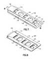
- FIG. 7is a top perspective view of an interlocking wafer serving as an expansion member to expand the interbody fusion device to the expanded condition shown in FIG. 3 .
- FIG. 8is a bottom perspective view of the interlocking wafer shown in FIG. 7 .
- FIG. 9is cross section of the interlocking wafer of FIG. 7 as seen along viewing lines IX-IX of FIG. 7 .
- FIG. 10is a cross section of the expanded interbody fusion device as seen along the viewing lines IV-IV of FIG. 3 .
- FIG. 11is a cross section of the expanded interbody fusion device as seen along the viewing lines XI-XI of FIG. 3 .
- FIGS. 12 and 13are rear and front perspective views respectively of an expandable interbody fusion device in unexpanded condition in accordance with another embodiment of the present invention.
- FIG. 14is a front perspective view of the expandable interbody fusion device of FIG. 13 in expanded condition.
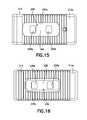
- FIG. 15is a top plan view of the interbody fusion device of FIG. 12 .
- FIG. 16is a bottom plan view of the interbody fusion device of FIG. 12 .
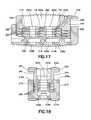
- FIG. 17is a cross section of the expanded interbody fusion device as seen along the viewing lines XVII-XVII of FIG. 14 .
- FIG. 18is a cross section of the expanded interbody fusion device as seen along the viewing lines XVIII-XVIII of FIG. 14 .
- an expandable interbody fusion device 10includes a first superior endplate 12 and a second inferior endplate 14 , as shown in FIGS. 1-3 .
- the superior outer surface 12 a and the inferior outer surface 14 a of the endplates 12 and 14each define engagement ribs 12 b and 14 b that are configured to engage or grip the vertebral endplates of opposed vertebral bodies in a spine.
- the ribs 12 b and 14 bare configured to prevent expulsion of the device 10 under normal spinal loads.
- the ribs as shownmay have a pyramidal configuration or they may include a saw tooth shape that is inclined toward the opening through which the device is inserted into the intradiscal space between opposing vertebral bodies.
- the interbody fusion device 10has a height across the superior and inferior endplates 12 , 14 in the unexpanded condition that is less than the normal anatomic height of a typical intradiscal space.
- the inventioncontemplates that a series of expansion members, such as interlocking wafers 100 as will be described, are introduced into the device 10 to distract the opposing vertebrae by separating the superior and inferior endplates 12 , 14 in situ. Insertion of the wafers 100 separates the endplates 12 , 14 to expand the height of the device within the intradiscal space and to ultimately restore the normal anatomic height of the disc space. Expansion devices of this type are shown and described in the '998 patent, the '688 patent and the '867 patent described hereinabove and incorporated herein by reference.
- the present inventioncontemplates an improved interbody fusion device 10 that particularly includes openings and holes that define graft chambers for containment of materials that promote bone fusion through the device between opposing vertebral bodies.
- the inferior endplate 14 of the interbody fusion device 10 as shown in FIGS. 1-3is elongate and comprises a pair of oppositely spaced apart sidewalls 16 and 18 extending along the longitudinal direction and projecting upwardly from outer surface 14 a .
- a pair of spaced apart end walls 20 and 22extend laterally across the device and project upwardly from the outer surface 14 a .
- End wall 20is disposed at the rear or proximal end of the device 10 and end wall 22 is disposed at the front or distal end of the device 10 .
- the side walls 16 , 18 together with rear end wall 20 and front end wall 22form an open, upwardly facing full bounded cavity 24 as shown in FIGS. 3 and 4 .
- the inferior plate 14 as shown in FIGS. 1 and 4defines a wafer channel 26 through the rear end wall 20 and through which the wafers 100 which serve as expansion members are introduced.
- the inferior endplate 14includes a pair of opposite ledges 28 that define an upper support surface on which each wafer 100 is supported as it introduced into the wafer channel 26 , as will be described.
- the inferior endplate 14also defines an inserter channel 30 that is below and in communication with the wafer channel 26 .
- the ledges 28define the bottom surface of the cavity 24 .
- the inserter channel 30receives a wafer track (not shown) for introduction of the wafers 100 as described in the '688 patent incorporated herein by reference. More specifically the inserter channel 30 includes a number of severable posts 32 projecting upward therein that are configured to engage an insertion plate and a release plate in a manner as described in the '688 patent.
- each opposite side wall 16 , 18 of the inferior endplate 14has on an interior surface 16 b thereof a pair of ribs 34 projecting into the cavity 24 , the ribs 34 being spaced lengthwise on the interior of each side wall 16 , 18 .
- Each side wall 16 , 18further defines upper surfaces 16 a and 18 a extending lengthwise thereon and generally parallel to each other.
- Rear end wall 20defines a recess 20 a extending therein at that the upper surface thereof and front end wall 22 defines a recess 22 a extending therein at the upper surface thereof.
- the inferior endplate 14includes graft chambers defined by a pair of spaced openings 36 extending in alignment along the longitudinal direction.
- the openings 36extend through the outer surface 14 a of the inferior endplate 14 , through the support surfaces defined by ledges 28 and communicate with the cavity 24 .
- a web 38extends between the pair of openings 36 , the web 38 supporting one of the posts 32 that is used to engage an insertion plate and a release plate as indicated hereinabove.
- One other post 32is disposed between a first opening 36 and the rear end wall 20 and a further post 32 is disposed between the second opening 36 and the front end wall 22 , the three posts 32 and two openings 36 extending linearly along the longitudinal direction of the inferior endplate 14 .
- Each opening 36includes therearound a countersink surface 36 a as shown in FIG. 6 for receipt of bone graft to thereby increase the surface area of contact between such bone graft and the endplate of a vertebral body.
- At least one radiopaque marker 39may be included on the inferior endplate 14 , such as adjacent the proximal end of side wall 16 and distal end of sidewall 18 , as shown in FIGS. 1-2 to assist in the visualization of the insertion of device 10 into the intradiscal space.
- the superior endplate 12 as shown in FIGS. 1-3 and 10 - 11is elongate and comprises a hub 40 having pair of side surfaces 42 and 44 extending longitudinally on each side of the hub 40 and a pair of end surfaces 46 and 48 extending respectively at the proximal end and the distal end of the superior endplate 12 .
- the hub 40is sized and configured to fit within the cavity 24 in relatively close fit between the side walls 16 and 18 and the end walls 20 and 22 of the inferior endplate 14 .
- the lower surface 50 of the hub 40( FIG. 11 ) includes a shaped configuration defined by wafer mating features 52 that are substantially identical to the mating features on the lower surface of each wafer 100 , as will be described.
- Superior endplate 12includes a flange 54 projecting outwardly and longitudinally from the hub 40 at the rear proximal end surface 46 and a flange 56 projecting outwardly and longitudinally from the hub 40 at the front distal end surface 48 .
- the hub 40defines a groove 58 and 60 as shown in FIGS. 3 and 11 extending along each side 42 and 44 thereof that is configured to engage the ribs 34 of the inferior endplate 14 . This engagement temporarily holds the superior and inferior endplates together as the device 10 is introduced into the intradiscal space to be distracted.
- the superior endplate 12includes a graft chamber defined by a multi-contoured opening 62 extending through the upper surface 12 a and the lower surface 50 .
- the opening 62is considered multi-contoured since it has one configuration opening at the upper surface 12 a and a different configuration opening at the lower surface 50 .
- upper portion of opening 62is a single, oval-shaped opening 62 a .
- the lower portion of opening 62comprises a pair of generally circular openings 62 b separated by a cross member 64 disposed generally centrally and transversely across superior endplate 12 in the lateral direction.
- Openings 62 bextend generally linearly along the longitudinal direction of superior endplate 12 and are disposed therethrough such that in assembly with inferior endplate 14 openings 62 b are generally in alignment in the elongate direction with openings 36 through inferior endplate 14 . While the provision of cross member 64 may tend to reduce the area through which the bone graft may flow upon injection into the device 10 , it should be appreciated that the cross member 64 at the lower portion of superior endplate 12 provides strength to the superior endplate 12 while allowing greater bone graft area at the outer surface 12 a . In addition, cross member 64 allows for a locking location for the uppermost wafer 100 , as will be described.
- Radiopaque markers 66may be included on the outer surface 12 a of superior endplate 12 as shown, for example in FIG. 5 .
- the wafer 100is elongate and has an upper surface 102 and a lower surface 104 , both of which are generally planar so that the wafers can form a stable stack within the interbody fusion device 10 .
- the trailing proximal end 106includes a downward-facing sloped surface 108 that corresponds angularly to an upward-facing surface 110 on the leading distal end 112 of the wafer 100 .
- the two sloped surfaceshelp displace an earlier inserted wafer 100 upon introduction of a new wafer. More specifically, when a first wafer is within the wafer channel 26 , resting on the ledges 28 ( FIG.
- the wafer 100further includes notches or indentations 114 that are configured to receive the ribs 34 on the inner side walls 16 , 18 of the inferior plate 14 (see FIG. 11 ) in a manner similar to the grooves 58 and 60 in the hub 40 of the superior endplate 12 .
- the wafer 100includes several features for interlocking engagement to the hub 40 and to adjacent wafers 100 in a complementary interlocking mating interface.
- One particular featureincludes a series of locking elements defined by resiliently deflectable prongs 116 that project outwardly above the upper surface 102 of the wafer.
- the prongs 116are disposed along the wafer 100 , extending lengthwise in alignment and defining a plurality of resiliently deflectable locking surfaces therealong.
- the lower surface 104 of each wafer 100 as shown in FIGS. 8 and 11also defines a T-slot configuration for mating with a T-bar configuration on the upper surface 102 of a successive wafer 100 .
- the respective T-bar and T-slot configurationsmay be formed on either the upper surface or the lower surface of a wafer 100 as desired.
- the structure and function of a wafer 100 and the prongs 116are more fully described in the '867 patent, incorporated herein by reference.
- there are three prongs 116extending generally linearly along the elongate longitudinal direction.
- a pair of holes 118extends through the upper surface 102 and the lower surface 104 of each wafer 100 .
- the holes 118are provided to allow bone graft to flow through the wafers, the holes 118 being disposed along the longitudinal direction with at least one hole 118 being situated between each pair of prongs 116 .
- prongs 116 and holes 118may be provided in a wafer 100 within the scope of the present invention.
- the number of prongs 116 and holes 118may be adjusted based on the length of the wafer 100 .
- the superior and inferior endplates 12 and 14are configured to be initially releasably engaged when the device 10 is unexpanded, as shown in FIGS. 1 and 2 .
- the device 10is attached to a track assembly as described in the '867 patent.
- the hub 40is disposed within the cavity 24 of inferior endplate 14 with the ribs 34 on the interior surfaces of side walls 16 , 18 engaging the grooves 58 and 60 extending along each side of the hub 40 .
- the lower surface 50 of hub 40is on or closely adjacent to the wafer support ledges 28 in facing relationship. This engagement temporarily holds the superior and inferior endplates together as the device 10 is introduced into the intradiscal space to be distracted.
- the outer surface 12 a of the superior endplate 12is substantially flush with the upper surfaces 16 a and 18 a of the sidewalls 16 and 18 , with the flanges 54 and 56 residing in recesses 20 a and 22 a of the rear end wall 20 and the front end wall 22 of the inferior endplate 14 , as illustrated in FIGS. 1 and 2 .
- Such nesting of the superior endplate 12 within inferior endplate 14allows for lower height of the unexpanded device 10 .
- FIGS. 10-11The manner in which the interbody fusion device 10 is expanded is illustrated in FIGS. 10-11 .
- the interlocking features on the upper surface 102 of the wafer 100engage the mating features 52 on the lower surface 50 of superior endplate 12 lifting the superior endplate 12 upwardly within the cavity 24 between sidewalls 16 , 18 and breaking the initial releasable engagement.
- the holes 118 in the wafer 100are located to be in alignment and communication with the openings 62 b extending through the lower surface 50 of inferior endplate 12 .
- the locking elements 116lockingly engage the lower surface 50 , one adjacent each of the distal and proximal ends of superior endplate 12 and the generally central locking element lockingly engaging the lower surface of cross member 64 extending between the openings 62 b .
- This processcontinues with each successive wafer 100 inserted beneath a previously inserted wafer 100 until a complete stack is formed, as depicted in FIGS. 10-11 .
- the locking elements 116lockingly engage the mating features on the lower surfaces of each previously introduced wafer 100 , with the holes 118 of each wafer 100 being inserted such that they are in alignment and communication with the holes 118 of each previously introduced wafer 100 .
- the lowermost wafer 100is supported on the support surfaces of ledges 28 with the holes 118 therethrough being in alignment and communication with the openings 36 extending through inferior endplate 14 . It should be noted that preferably all the wafers 100 , but at least the two lowermost wafers 100 , are contained within and constricted by the opposing side walls 16 , 18 and the rear and front end walls 20 , 22 so as to provide additional resistance against torsional movement of the spine.
- the manner in which the expanded interbody fusion device 10 is released from the wafer track assembly of the insertion instrument by the severing of posts 32is fully described in the '867 patent.
- a suitable bone filler or bone graft to promote fusion between opposing vertebral bodiesmay be inserted into the expanded device 10 as well as into the intradiscal space adjacent to device 10 .
- the wafer insertion channel 30provides access into the expanded device 10 .
- a suitable graft insertion instrumentmay be used to inject bone graft under pressure into the expanded device 10 . Under an appropriate pressure, such bone graft will flow through the holes 118 extending through the wafers 100 and into the openings 36 through the inferior endplate 14 and into the multi-contoured opening 62 through the superior endplate 12 .
- bone graftwill also flow into the countersink surfaces 36 a surrounding the openings 36 so as to further increase contact area between the bone graft and the endplate of the inferior vertebral body. Injection of the bone graft will continue until the graft is stress loaded against the endplates of the opposing vertebral bodies.
- bone graftmay be pre-loaded into an unexpanded device 10 prior to insertion of the device 10 into the intradiscal disc space.
- Suitable bone graft materialsmay include autograph bone, allograft bone, bone morphogenic protein (BMP) and xenograft and synthetic derived bone substitutes, as described for example, in the '998 patent.
- a material with a bone fusion promoting substancesuch as a sponge saturated with BMP, may be placed in the single opening 62 a of the multi-contoured opening 62 and supported by the cross member 64 . This will allow the fusion promoting substance to be pre-loaded into device 10 and not be disrupted upon expansion of device 10 by insertion of wafers 100 as described herein.
- each of the components of the device 10namely the superior endplate 12 , inferior endplate 14 and the wafers 100 described herein, be formed of a biocompatible material that is sufficiently rigid to form a solid stack as the successive wafers are inserted into the device.
- the componentsare formed of PEEK or a carbon-fiber reinforced PEEK, or similar polymeric material.
- the superior and inferior platesmay be formed of a biological material, such as a bone graft material, or an osteoconductive or osteoinductive material.
- the device 10has particular utility as a lateral implant for insertion into the intradiscal space using a lateral approach as more fully described in PCT Application No. PCT/US2012/054055, entitled “Lateral Approach Expandable Spinal Implant and Method”, filed on Sep. 7, 2012 and commonly assigned to the same assignee as the present invention, the disclosure of which is incorporated herein by reference in its entirety.
- the overall length L of the device 10 as shown in FIGS. 5-6including the lengths of both the superior endplate 12 and the inferior endplate 14 , is about 37 mm.
- the width Ws of the superior endplate 12is approximately 12.5 mm and the width Wi of the inferior endplate 14 is approximately 17.3 mm.
- the height of the unexpanded device 10 of FIGS. 1-2 with the superior endplate 12 fully nested within the inferior endplate 14is approximately 8 mm.
- the height of device 10may be expanded from an unexpanded height of approximately 8 mm to an expanded height of approximately 12 mm.
- the number of wafersmay vary depending upon the particular surgery and the initial height may also be different.
- device 10may be formed to have an initial unexpanded height of 9 mm and with the addition of five wafers 100 , each having a thickness of 1 mm, the height of device 10 may be increased to 14 mm.
- these dimensionsare only illustrative and that the dimensions of the device 10 and the number of wafers 100 to be inserted and their thicknesses may vary depending upon the application.
- the footprint of the outer surfaces of the superior and inferior endplates 12 , 14 that contacts the endplates of opposing vertebral bodiesis determined by the area defined by the perimeter of such outer surfaces.
- the footprint of outer surface 12 ais L times Ws, as shown in FIG. 5 .
- the footprintis approximately 461 mm 2 .
- the bone graft area that contacts the endplate of the superior vertebral bodyis defined by the area of the single opening 62 a , which in this example is approximately 95 mm 2 .
- the ratio of bone graft area to the footprint at outer surface 12 ais therefore about 20.6%.
- the footprint of the outer surface 14 a of the inferior endplate 14 that contacts the endplate of the inferior vertebral bodyis defined by the area, L times Wi, as shown in FIG. 6 .
- the footprintis approximately 639 mm 2 .
- the bone graft area that contacts the endplate of the superior vertebral bodyis defined by the total area of the two openings together with the countersink areas 36 a , which in this example is approximately 98 mm 2 .
- the ratio of bone graft area to the footprint at outer surface 14 ais therefore about 15.3%.
- An expandable interbody fusion device 200comprises a superior endplate 212 , an inferior endplate 214 and a plurality of interlocking wafers 300 .
- Components of interbody fusion device 200are substantially the same both structurally and functionally as like components of interbody fusion device 10 , except for several differences.
- the first differenceis that device 200 is of smaller size than device 10 and is particularly shorter in length.
- the device 200thus has particular utility as a spinal implant inserted posteriorly or posteriolaterally either bilaterally or unilaterally depending upon the surgical indication and the surgeon's preference.
- the second difference of device 200 over device 10is that the superior endplate 212 is not fully nested within the sidewalls 216 , 218 and the front end wall 220 and the rear end wall 222 of device 200 .
- Each side wall 216 , 218defines upper surfaces 216 a and 218 a extending lengthwise thereon.
- Rear end wall 220defines a recess 220 a extending therein at that the upper surface thereof and front end wall 222 defines an upper surface 222 a coplanar with upper surfaces 216 a and 218 a .
- Superior endplate 212includes a flange 254 projecting outwardly and longitudinally from the hub 240 at the rear proximal end surface 246 and a flange 256 projecting outwardly and longitudinally from the hub 240 at the front distal end surface 248 at the front distal end surface 248 .
- Flanges 257 and 259project outwardly and laterally from the hub 240 from hub side surfaces 242 and 244 , respectively.
- the flanges 256 , 257 and 259rest on top of respective upper surfaces 222 a , 216 a and 218 a with a flange 254 residing in recess 220 a . While not fully nested in a manner as provided with device 10 , the added expanse of the flanges 256 , 257 and 259 provides for a larger footprint than the fully nested structure.
- a third difference of device 200 over device 10is that device 200 has multi-contoured openings at both the upper surface 212 a and 214 a , as shown in FIGS. 15 and 16 .
- the superior endplate 212has an opening 262 therethrough, the upper portion of opening 262 being a single, oval-shaped opening 262 a .
- the lower portion of opening 262comprises a pair of generally rectangular openings 262 b separated by a cross member 264 disposed generally centrally and laterally across superior endplate 212 . Openings 262 b extend generally linearly along the longitudinal direction of superior endplate 12 .
- the inferior endplate 214has an opening 236 therethrough, the lower portion of opening 236 being a single, oval-shaped opening 236 a .
- opening 236comprises a pair of generally rectangular openings 236 b separated by a cross member 238 disposed generally centrally and laterally across inferior endplate 214 . Openings 236 b extend generally linearly along the longitudinal direction of superior endplate 12 and are disposed therethrough such that in assembly with superior endplate 212 openings 236 b are generally in alignment in the elongate direction with openings 262 b through superior endplate 212 .
- the area of bone graft contact with the endplates of opposing vertebral bodiesmay be maximized by the use of the multi-contoured openings 236 and 262 each of which has a substantially large single oval-shaped opening 236 a and 262 a , respectively, while maintaining strength of the endplates 212 , 214 due to the cross members 238 and 264 .
- a fourth difference of device 200 over device 10is that the ribs 212 b and 214 b are configured to include a saw tooth shape rather than the pyramidal configuration of the ribs 12 b and 14 b of the device 10 .
- the expansion members defined by interlocking wafers 300are substantially similar to wafers 100 except for size and are inserted in a similar manner such that once inserted the holes 318 are aligned and in communication with openings 236 b through the inferior endplate 214 and with openings 262 b through the superior endplate 212 .
- the overall length L of the device 200is about 25 mm and the overall width is approximately 12 mm.
- the height of the unexpanded device 10 of FIGS. 12-13is approximately 7 mm.
- the height of device 200may be expanded in 1 mm increments. As such, the insertion of one wafer 300 would increase the height of device 200 to 8 mm while the addition of three wafers 300 would increase the height to 10 mm.
- all the wafers 300but at least the two lowermost wafers 300 where more than a single wafer is inserted, be contained within and constricted by the opposing side walls 216 , 218 and the rear and front end walls 220 , 222 so as to provide additional resistance against torsional movement of the spine.
- other unexpanded starting heights and lengths of device 200may be contemplated as well as different number of wafers 300 and wafer thicknesses, depending upon the particular application.
- a device having an overall length of approximately 29 mm and a width of approximately 12 mmmay have an unexpanded height of about 9 mm with three wafers 300 inserted to thereby increase the height to about 12 mm.
- the footprint of outer surface 212 a of superior endplate 212is approximately 283 mm 2 .
- the bone graft area that contacts the endplate of the superior vertebral bodyis defined by the area of the single opening 262 a , which in this example is approximately 78 mm 2 .
- the ratio of bone graft area to the footprint at outer surface 212 ais therefore about 27.6%.
- the footprint of the outer surface 214 a of the inferior endplate 214 that contacts the endplate of the inferior vertebral body in this particular exampleis approximately 305 mm 2 .
- the bone graft area that contacts the endplate of the inferior vertebral bodyis defined by the area of the single opening 236 a , which in this example is approximately 78 mm 2 .
- the ratio of bone graft area to the footprint at outer surface 214 ais therefore about 25.6%. Accordingly, the ratio of bone graft area to the footprint at the outer surfaces of the expandable interbody fusion devices in the examples ranges from about 15 to 28%.
- the superior and inferior endplates of the expandable interbody fusion devicemay each have a single opening extending therethrough in communication and alignment with at least one expansion members defined by an interlocking wafer.
- Such waferwould have at least two locking elements thereon, one locking element being located on each side of the hole through such wafer, such that a locking engagement would be provided at each of the proximal and distal ends of the device.
- the illustrated embodimentshave been directed to interbody fusion of the spine, the expandable devices and wafers disclosed herein may be used in other applications that require distraction of tissue surfaces. Modifications in size may be necessary depending upon the body space being distracted.
Landscapes
- Health & Medical Sciences (AREA)
- Engineering & Computer Science (AREA)
- Biomedical Technology (AREA)
- Neurology (AREA)
- Orthopedic Medicine & Surgery (AREA)
- Cardiology (AREA)
- Oral & Maxillofacial Surgery (AREA)
- Transplantation (AREA)
- Heart & Thoracic Surgery (AREA)
- Vascular Medicine (AREA)
- Life Sciences & Earth Sciences (AREA)
- Animal Behavior & Ethology (AREA)
- General Health & Medical Sciences (AREA)
- Public Health (AREA)
- Veterinary Medicine (AREA)
- Prostheses (AREA)
Abstract
Description
Claims (15)
Priority Applications (3)
| Application Number | Priority Date | Filing Date | Title |
|---|---|---|---|
| US13/689,046US8715351B1 (en) | 2012-11-29 | 2012-11-29 | Expandable interbody fusion device with graft chambers |
| PCT/US2013/071998WO2014085448A1 (en) | 2012-11-29 | 2013-11-26 | Expandable interbody fusion device with graft chambers |
| US14/265,482US9480578B2 (en) | 2012-11-29 | 2014-04-30 | Expandable interbody fusion device with graft chambers |
Applications Claiming Priority (1)
| Application Number | Priority Date | Filing Date | Title |
|---|---|---|---|
| US13/689,046US8715351B1 (en) | 2012-11-29 | 2012-11-29 | Expandable interbody fusion device with graft chambers |
Related Child Applications (1)
| Application Number | Title | Priority Date | Filing Date |
|---|---|---|---|
| US14/265,482ContinuationUS9480578B2 (en) | 2012-11-29 | 2014-04-30 | Expandable interbody fusion device with graft chambers |
Publications (2)
| Publication Number | Publication Date |
|---|---|
| US8715351B1true US8715351B1 (en) | 2014-05-06 |
| US20140148903A1 US20140148903A1 (en) | 2014-05-29 |
Family
ID=50552751
Family Applications (2)
| Application Number | Title | Priority Date | Filing Date |
|---|---|---|---|
| US13/689,046ActiveUS8715351B1 (en) | 2012-11-29 | 2012-11-29 | Expandable interbody fusion device with graft chambers |
| US14/265,482Expired - Fee RelatedUS9480578B2 (en) | 2012-11-29 | 2014-04-30 | Expandable interbody fusion device with graft chambers |
Family Applications After (1)
| Application Number | Title | Priority Date | Filing Date |
|---|---|---|---|
| US14/265,482Expired - Fee RelatedUS9480578B2 (en) | 2012-11-29 | 2014-04-30 | Expandable interbody fusion device with graft chambers |
Country Status (2)
| Country | Link |
|---|---|
| US (2) | US8715351B1 (en) |
| WO (1) | WO2014085448A1 (en) |
Cited By (73)
| Publication number | Priority date | Publication date | Assignee | Title |
|---|---|---|---|---|
| US20130197648A1 (en)* | 2010-10-11 | 2013-08-01 | Heinrich Boehm | Implant for the spinal column and actuating instrument |
| US20140135936A1 (en)* | 2004-08-25 | 2014-05-15 | Spine Wave, Inc. | Expandable interbody fusion device |
| US20140207239A1 (en)* | 2011-09-09 | 2014-07-24 | Spine Wave, Inc. | Lateral approach expandable spinal implant and method |
| US20150164649A1 (en)* | 2008-03-14 | 2015-06-18 | DePuy Synthes Products, Inc. | Nested Expandable Sleeve Implant |
| US9078767B1 (en)* | 2014-03-06 | 2015-07-14 | Spine Wave, Inc. | Expandable spinal interbody fusion device |
| US20150282943A1 (en)* | 2014-03-06 | 2015-10-08 | Spine Wave, Inc. | Device for expanding and supporting body tissue |
| US9216096B2 (en) | 2010-03-16 | 2015-12-22 | Pinnacle Spine Group, Llc | Intervertebral implants and related tools |
| WO2015200058A1 (en)* | 2014-06-25 | 2015-12-30 | Spine Wave, Inc. | Expandable interbody fusion device with nested correction surface |
| US9265623B2 (en) | 2014-03-06 | 2016-02-23 | Spine Wave, Inc. | Method of expanding a spinal interbody fusion device |
| US9295562B2 (en) | 2008-01-17 | 2016-03-29 | DePuy Synthes Products, Inc. | Expandable intervertebral implant and associated method of manufacturing the same |
| US9320615B2 (en) | 2010-06-29 | 2016-04-26 | DePuy Synthes Products, Inc. | Distractible intervertebral implant |
| US9380932B1 (en) | 2011-11-02 | 2016-07-05 | Pinnacle Spine Group, Llc | Retractor devices for minimally invasive access to the spine |
| US9402737B2 (en) | 2007-06-26 | 2016-08-02 | DePuy Synthes Products, Inc. | Highly lordosed fusion cage |
| US9414934B2 (en) | 2008-04-05 | 2016-08-16 | DePuy Synthes Products, Inc. | Expandable intervertebral implant |
| US9427264B2 (en) | 2008-12-05 | 2016-08-30 | Jeffrey KLEINER | Apparatus and method of spinal implant and fusion |
| US9439782B2 (en) | 2008-02-06 | 2016-09-13 | Jeffrey B. Kleiner | Spinal fusion cage system with inserter |
| US9439783B2 (en) | 2014-03-06 | 2016-09-13 | Spine Wave, Inc. | Inserter for expanding body tissue |
| US9526620B2 (en) | 2009-03-30 | 2016-12-27 | DePuy Synthes Products, Inc. | Zero profile spinal fusion cage |
| US9561117B2 (en) | 2012-07-26 | 2017-02-07 | DePuy Synthes Products, Inc. | Expandable implant |
| JP2017506981A (en)* | 2014-03-06 | 2017-03-16 | スパイン・ウェーヴ・インコーポレイテッド | Expandable spinal interbody fusion device |
| US9629729B2 (en) | 2009-09-18 | 2017-04-25 | Spinal Surgical Strategies, Llc | Biological delivery system with adaptable fusion cage interface |
| US9717601B2 (en) | 2013-02-28 | 2017-08-01 | DePuy Synthes Products, Inc. | Expandable intervertebral implant, system, kit and method |
| US9724207B2 (en) | 2003-02-14 | 2017-08-08 | DePuy Synthes Products, Inc. | In-situ formed intervertebral fusion device and method |
| WO2017147340A1 (en)* | 2016-02-23 | 2017-08-31 | Life Spine, Inc. (A Delaware Corporation) | Expandable lateral spine cage with reverse dovetail configuration |
| US9750552B2 (en) | 2009-07-06 | 2017-09-05 | DePuy Synthes Products, Inc. | Expandable fixation assemblies |
| USD797290S1 (en) | 2015-10-19 | 2017-09-12 | Spinal Surgical Strategies, Llc | Bone graft delivery tool |
| US9826988B2 (en) | 2009-02-06 | 2017-11-28 | Kleiner Intellectual Property, Llc | Devices and methods for preparing an intervertebral workspace |
| US9833334B2 (en) | 2010-06-24 | 2017-12-05 | DePuy Synthes Products, Inc. | Enhanced cage insertion assembly |
| US9861495B2 (en) | 2013-03-14 | 2018-01-09 | Raed M. Ali, M.D., Inc. | Lateral interbody fusion devices, systems and methods |
| US9913727B2 (en) | 2015-07-02 | 2018-03-13 | Medos International Sarl | Expandable implant |
| US9949769B2 (en) | 2004-03-06 | 2018-04-24 | DePuy Synthes Products, Inc. | Dynamized interspinal implant |
| US9980750B2 (en) | 2011-03-18 | 2018-05-29 | Raed M. Ali, M.D., Inc. | Spinal fusion devices and systems |
| US9980827B2 (en) | 2007-05-31 | 2018-05-29 | Spine Wave, Inc. | Expandable interbody fusion device |
| US9993349B2 (en) | 2002-06-27 | 2018-06-12 | DePuy Synthes Products, Inc. | Intervertebral disc |
| EP3357459A1 (en) | 2017-02-03 | 2018-08-08 | Spinal Surgical Strategies, LLC | Bone graft delivery device with positioning handle |
| US10070970B2 (en) | 2013-03-14 | 2018-09-11 | Pinnacle Spine Group, Llc | Interbody implants and graft delivery systems |
| US10159582B2 (en) | 2011-09-16 | 2018-12-25 | DePuy Synthes Products, Inc. | Removable, bone-securing cover plate for intervertebral fusion cage |
| US10195053B2 (en) | 2009-09-18 | 2019-02-05 | Spinal Surgical Strategies, Llc | Bone graft delivery system and method for using same |
| US10245159B1 (en) | 2009-09-18 | 2019-04-02 | Spinal Surgical Strategies, Llc | Bone graft delivery system and method for using same |
| CN109953841A (en)* | 2019-04-10 | 2019-07-02 | 上海交通大学医学院附属第九人民医院 | A construction method of a personalized porous interbody cage |
| US10369015B2 (en) | 2010-09-23 | 2019-08-06 | DePuy Synthes Products, Inc. | Implant inserter having a laterally-extending dovetail engagement feature |
| US10390963B2 (en) | 2006-12-07 | 2019-08-27 | DePuy Synthes Products, Inc. | Intervertebral implant |
| US10398563B2 (en) | 2017-05-08 | 2019-09-03 | Medos International Sarl | Expandable cage |
| US10433974B2 (en) | 2003-06-30 | 2019-10-08 | DePuy Synthes Products, Inc. | Intervertebral implant with conformable endplate |
| US10500062B2 (en) | 2009-12-10 | 2019-12-10 | DePuy Synthes Products, Inc. | Bellows-like expandable interbody fusion cage |
| US10537436B2 (en) | 2016-11-01 | 2020-01-21 | DePuy Synthes Products, Inc. | Curved expandable cage |
| US10687962B2 (en) | 2013-03-14 | 2020-06-23 | Raed M. Ali, M.D., Inc. | Interbody fusion devices, systems and methods |
| US10888433B2 (en) | 2016-12-14 | 2021-01-12 | DePuy Synthes Products, Inc. | Intervertebral implant inserter and related methods |
| US10940016B2 (en) | 2017-07-05 | 2021-03-09 | Medos International Sarl | Expandable intervertebral fusion cage |
| US10973656B2 (en) | 2009-09-18 | 2021-04-13 | Spinal Surgical Strategies, Inc. | Bone graft delivery system and method for using same |
| EP3291769B1 (en)* | 2015-05-05 | 2021-04-14 | RS-Technik Cad-Cam GmbH | Interbody implant |
| US10987228B2 (en) | 2011-03-18 | 2021-04-27 | Raed M. Ali, M.D., Inc. | Devices and methods for transpedicular stabilization of the spine |
| US11065132B2 (en) | 2014-03-06 | 2021-07-20 | Spine Wave, Inc. | Method of expanding a space between opposing tissue surfaces |
| US11116644B2 (en) | 2018-05-25 | 2021-09-14 | Mirus Llc | Multiple expansion stage interbody devices |
| US11185420B2 (en)* | 2016-12-30 | 2021-11-30 | Tobb Ekonomi Ve Teknoloji Universitesi | Expandable cage |
| US11278423B2 (en) | 2017-09-29 | 2022-03-22 | Mirus Llc | Expandable interbody devices |
| US11278425B2 (en)* | 2016-02-20 | 2022-03-22 | Seth K. WILLIAMS | System and method for spine fusion using an expandable cage |
| US11344424B2 (en) | 2017-06-14 | 2022-05-31 | Medos International Sarl | Expandable intervertebral implant and related methods |
| US11419735B2 (en) | 2020-12-18 | 2022-08-23 | Spine Wave, Inc. | Expandable TLIF device and related insertion and grafting instrumentation |
| US11426290B2 (en) | 2015-03-06 | 2022-08-30 | DePuy Synthes Products, Inc. | Expandable intervertebral implant, system, kit and method |
| US11426286B2 (en) | 2020-03-06 | 2022-08-30 | Eit Emerging Implant Technologies Gmbh | Expandable intervertebral implant |
| US11446156B2 (en) | 2018-10-25 | 2022-09-20 | Medos International Sarl | Expandable intervertebral implant, inserter instrument, and related methods |
| US11452607B2 (en) | 2010-10-11 | 2022-09-27 | DePuy Synthes Products, Inc. | Expandable interspinous process spacer implant |
| US11497619B2 (en) | 2013-03-07 | 2022-11-15 | DePuy Synthes Products, Inc. | Intervertebral implant |
| US11510788B2 (en) | 2016-06-28 | 2022-11-29 | Eit Emerging Implant Technologies Gmbh | Expandable, angularly adjustable intervertebral cages |
| US11596523B2 (en) | 2016-06-28 | 2023-03-07 | Eit Emerging Implant Technologies Gmbh | Expandable and angularly adjustable articulating intervertebral cages |
| US11666455B2 (en) | 2009-09-18 | 2023-06-06 | Spinal Surgical Strategies, Inc., A Nevada Corporation | Bone graft delivery devices, systems and kits |
| US11752009B2 (en) | 2021-04-06 | 2023-09-12 | Medos International Sarl | Expandable intervertebral fusion cage |
| US11850160B2 (en) | 2021-03-26 | 2023-12-26 | Medos International Sarl | Expandable lordotic intervertebral fusion cage |
| US11911287B2 (en) | 2010-06-24 | 2024-02-27 | DePuy Synthes Products, Inc. | Lateral spondylolisthesis reduction cage |
| US12090064B2 (en) | 2022-03-01 | 2024-09-17 | Medos International Sarl | Stabilization members for expandable intervertebral implants, and related systems and methods |
| US12279972B2 (en) | 2008-05-22 | 2025-04-22 | Spinal Surgical Strategies, Inc. | Spinal fusion cage system with inserter |
| US12440346B2 (en) | 2023-03-31 | 2025-10-14 | DePuy Synthes Products, Inc. | Expandable intervertebral implant |
Families Citing this family (7)
| Publication number | Priority date | Publication date | Assignee | Title |
|---|---|---|---|---|
| US8900312B2 (en) | 2013-03-12 | 2014-12-02 | Spine Wave, Inc. | Expandable interbody fusion device with graft chambers |
| US11311312B2 (en) | 2013-03-15 | 2022-04-26 | Medtronic, Inc. | Subcutaneous delivery tool |
| USD955579S1 (en) | 2019-04-26 | 2022-06-21 | Warsaw Orthopedic, Inc. | Surgical implant |
| USD948048S1 (en) | 2019-04-26 | 2022-04-05 | Warsaw Orthopedic, Inc. | Surgical implant |
| US11464648B2 (en) | 2019-09-09 | 2022-10-11 | Amplify Surgical, Inc. | Multi-portal surgical systems |
| US11678906B2 (en) | 2019-09-09 | 2023-06-20 | Amplify Surgical, Inc. | Multi-portal surgical systems, cannulas, and related technologies |
| US11950770B1 (en) | 2022-12-01 | 2024-04-09 | Amplify Surgical, Inc. | Multi-portal split cannulas, endoscopic hemostatic dispensers and surgical tools |
Citations (92)
| Publication number | Priority date | Publication date | Assignee | Title |
|---|---|---|---|---|
| US3486505A (en) | 1967-05-22 | 1969-12-30 | Gordon M Morrison | Orthopedic surgical instrument |
| US4524766A (en) | 1982-01-07 | 1985-06-25 | Petersen Thomas D | Surgical knee alignment method and system |
| US4683476A (en) | 1984-06-22 | 1987-07-28 | Benson S.A. | Drawing machine having automatically replaced writing members and apparatus therefor |
| US4736738A (en) | 1984-07-09 | 1988-04-12 | Matej Lipovsek | Instrument kit and procedure for performing posterior lumbar interbody fusion |
| US4755797A (en) | 1986-08-14 | 1988-07-05 | Nittan Co., Ltd. | Fire alarm apparatus |
| US4863476A (en) | 1986-08-29 | 1989-09-05 | Shepperd John A N | Spinal implant |
| US4888024A (en) | 1985-11-08 | 1989-12-19 | Powlan Roy Y | Prosthetic device and method of fixation within the medullary cavity of bones |
| FR2639823A1 (en) | 1988-12-06 | 1990-06-08 | Garcia Alain | Replacement of the nucleus of the intervertebral disc by a polyurethane polymerised in situ |
| US5059193A (en) | 1989-11-20 | 1991-10-22 | Spine-Tech, Inc. | Expandable spinal implant and surgical method |
| US5192327A (en) | 1991-03-22 | 1993-03-09 | Brantigan John W | Surgical prosthetic implant for vertebrae |
| US5192326A (en) | 1990-12-21 | 1993-03-09 | Pfizer Hospital Products Group, Inc. | Hydrogel bead intervertebral disc nucleus |
| US5197971A (en) | 1990-03-02 | 1993-03-30 | Bonutti Peter M | Arthroscopic retractor and method of using the same |
| US5298254A (en) | 1989-09-21 | 1994-03-29 | Osteotech, Inc. | Shaped, swollen demineralized bone and its use in bone repair |
| EP0621020A1 (en) | 1993-04-21 | 1994-10-26 | SULZER Medizinaltechnik AG | Intervertebral prosthesis and method of implanting such a prosthesis |
| US5431658A (en) | 1994-02-14 | 1995-07-11 | Moskovich; Ronald | Facilitator for vertebrae grafts and prostheses |
| FR2719763A1 (en) | 1994-05-11 | 1995-11-17 | Jean Taylor | Vertebral implant. |
| US5505732A (en) | 1988-06-13 | 1996-04-09 | Michelson; Gary K. | Apparatus and method of inserting spinal implants |
| US5514180A (en) | 1994-01-14 | 1996-05-07 | Heggeness; Michael H. | Prosthetic intervertebral devices |
| US5522899A (en) | 1988-06-28 | 1996-06-04 | Sofamor Danek Properties, Inc. | Artificial spinal fusion implants |
| US5571109A (en) | 1993-08-26 | 1996-11-05 | Man Ceramics Gmbh | System for the immobilization of vertebrae |
| US5591235A (en) | 1995-03-15 | 1997-01-07 | Kuslich; Stephen D. | Spinal fixation device |
| US5609636A (en)* | 1994-05-23 | 1997-03-11 | Spine-Tech, Inc. | Spinal implant |
| US5645599A (en) | 1994-07-26 | 1997-07-08 | Fixano | Interspinal vertebral implant |
| US5756127A (en) | 1996-10-29 | 1998-05-26 | Wright Medical Technology, Inc. | Implantable bioresorbable string of calcium sulfate beads |
| US5766252A (en) | 1995-01-24 | 1998-06-16 | Osteonics Corp. | Interbody spinal prosthetic implant and method |
| US5836948A (en) | 1997-01-02 | 1998-11-17 | Saint Francis Medical Technologies, Llc | Spine distraction implant and method |
| US5860977A (en) | 1997-01-02 | 1999-01-19 | Saint Francis Medical Technologies, Llc | Spine distraction implant and method |
| WO1999002214A1 (en) | 1997-07-09 | 1999-01-21 | Tegementa, L.L.C. | Interbody device and method for treatment of osteoporotic vertebral collapse |
| US5891147A (en) | 1996-06-25 | 1999-04-06 | Sdgi Holdings, Inc. | Minimally invasive spinal surgical methods & instruments |
| US5951553A (en) | 1997-07-14 | 1999-09-14 | Sdgi Holdings, Inc. | Methods and apparatus for fusionless treatment of spinal deformities |
| US5980522A (en) | 1994-07-22 | 1999-11-09 | Koros; Tibor | Expandable spinal implants |
| US6033411A (en) | 1997-10-14 | 2000-03-07 | Parallax Medical Inc. | Precision depth guided instruments for use in vertebroplasty |
| US6045579A (en) | 1997-05-01 | 2000-04-04 | Spinal Concepts, Inc. | Adjustable height fusion device |
| US6066154A (en) | 1994-01-26 | 2000-05-23 | Kyphon Inc. | Inflatable device for use in surgical protocol relating to fixation of bone |
| US6110179A (en) | 1998-03-02 | 2000-08-29 | Benoist Girard Sas | Prosthesis inserter |
| US6110210A (en) | 1999-04-08 | 2000-08-29 | Raymedica, Inc. | Prosthetic spinal disc nucleus having selectively coupled bodies |
| US6159244A (en) | 1999-07-30 | 2000-12-12 | Suddaby; Loubert | Expandable variable angle intervertebral fusion implant |
| US6159211A (en) | 1998-10-22 | 2000-12-12 | Depuy Acromed, Inc. | Stackable cage system for corpectomy/vertebrectomy |
| US6190414B1 (en) | 1996-10-31 | 2001-02-20 | Surgical Dynamics Inc. | Apparatus for fusion of adjacent bone structures |
| US6200347B1 (en) | 1999-01-05 | 2001-03-13 | Lifenet | Composite bone graft, method of making and using same |
| US6241771B1 (en) | 1997-08-13 | 2001-06-05 | Cambridge Scientific, Inc. | Resorbable interbody spinal fusion devices |
| US6273916B1 (en) | 1999-09-02 | 2001-08-14 | Cook Incorporated | Method and apparatus for strengthening vertebral bodies |
| US6279916B1 (en) | 1995-06-29 | 2001-08-28 | Friedhelm Stecher | Flat gasket and method of producing the same |
| US6287308B1 (en) | 1997-07-14 | 2001-09-11 | Sdgi Holdings, Inc. | Methods and apparatus for fusionless treatment of spinal deformities |
| US6287309B1 (en) | 1997-09-23 | 2001-09-11 | Dimso (Distribution Medicale Du Sudouest) | Screw and plate system for backbone osteosynthesis |
| US6290724B1 (en) | 1998-05-27 | 2001-09-18 | Nuvasive, Inc. | Methods for separating and stabilizing adjacent vertebrae |
| US20020026195A1 (en) | 2000-04-07 | 2002-02-28 | Kyphon Inc. | Insertion devices and method of use |
| US6387130B1 (en) | 1999-04-16 | 2002-05-14 | Nuvasive, Inc. | Segmented linked intervertebral implant systems |
| US6395034B1 (en) | 1999-11-24 | 2002-05-28 | Loubert Suddaby | Intervertebral disc prosthesis |
| US6402750B1 (en) | 2000-04-04 | 2002-06-11 | Spinlabs, Llc | Devices and methods for the treatment of spinal disorders |
| US6419705B1 (en) | 1999-06-23 | 2002-07-16 | Sulzer Spine-Tech Inc. | Expandable fusion device and method |
| US6432107B1 (en) | 2000-01-15 | 2002-08-13 | Bret A. Ferree | Enhanced surface area spinal fusion devices |
| US6436142B1 (en) | 1998-12-14 | 2002-08-20 | Phoenix Biomedical Corp. | System for stabilizing the vertebral column including deployment instruments and variable expansion inserts therefor |
| US20020147497A1 (en) | 2001-04-06 | 2002-10-10 | Integrated Vascular Systems, Inc. | Methods for treating spinal discs |
| US6478800B1 (en) | 2000-05-08 | 2002-11-12 | Depuy Acromed, Inc. | Medical installation tool |
| US20020177897A1 (en) | 2001-02-04 | 2002-11-28 | Michelson Gary K. | Instrumentation and method for inserting and deploying and expandable interbody spinal fusion implant |
| US6488710B2 (en) | 1999-07-02 | 2002-12-03 | Petrus Besselink | Reinforced expandable cage and method of deploying |
| US6500205B1 (en) | 2000-04-19 | 2002-12-31 | Gary K. Michelson | Expandable threaded arcuate interbody spinal fusion implant with cylindrical configuration during insertion |
| US6520993B2 (en) | 2000-12-29 | 2003-02-18 | Depuy Acromed, Inc. | Spinal implant |
| US6562074B2 (en) | 2001-10-17 | 2003-05-13 | Medicinelodge, Inc. | Adjustable bone fusion implant and method |
| US6595998B2 (en) | 2001-03-08 | 2003-07-22 | Spinewave, Inc. | Tissue distraction device |
| US20030171812A1 (en) | 2001-12-31 | 2003-09-11 | Ilan Grunberg | Minimally invasive modular support implant device and method |
| US6620196B1 (en) | 2000-08-30 | 2003-09-16 | Sdgi Holdings, Inc. | Intervertebral disc nucleus implants and methods |
| US6656178B1 (en) | 1999-07-28 | 2003-12-02 | Baat B.V. Engineering | Vertebral-column fusion devices and surgical methods |
| US6666888B1 (en)* | 2000-08-23 | 2003-12-23 | Roger P. Jackson | Threaded fusion cage with enhanced anterior support |
| US6726691B2 (en) | 1998-08-14 | 2004-04-27 | Kyphon Inc. | Methods for treating fractured and/or diseased bone |
| US6740093B2 (en) | 2000-02-28 | 2004-05-25 | Stephen Hochschuler | Method and apparatus for treating a vertebral body |
| US6837904B2 (en) | 2001-07-16 | 2005-01-04 | Spinecore, Inc. | Method of surgically treating scoliosis |
| US20050027364A1 (en) | 2003-08-01 | 2005-02-03 | Kim Daniel H. | Prosthetic intervertebral disc and methods for using the same |
| US6852095B1 (en) | 1997-07-09 | 2005-02-08 | Charles D. Ray | Interbody device and method for treatment of osteoporotic vertebral collapse |
| US6852126B2 (en) | 2000-07-17 | 2005-02-08 | Nuvasive, Inc. | Stackable interlocking intervertebral support system |
| US6908485B2 (en)* | 1998-01-30 | 2005-06-21 | Stryker Spine | Implant for replacing a vertebra |
| US6997929B2 (en) | 2003-05-16 | 2006-02-14 | Spine Wave, Inc. | Tissue distraction device |
| US20060058807A1 (en) | 2004-08-25 | 2006-03-16 | Michael Landry | Expandable interbody fusion device |
| US7044972B2 (en) | 2001-01-30 | 2006-05-16 | Synthes Ag Chur | Bone implant, in particular, an inter-vertebral implant |
| US20060129244A1 (en) | 2004-10-25 | 2006-06-15 | Alphaspine, Inc. | Expandable intervertebral spacer method and apparatus |
| US7094257B2 (en) | 2003-02-14 | 2006-08-22 | Zimmer Spine, Inc. | Expandable intervertebral implant cage |
| US7118580B1 (en) | 1999-09-14 | 2006-10-10 | Spine Solutions Inc. | Instrument for inserting intervertebral implants |
| US20080161924A1 (en)* | 2007-01-02 | 2008-07-03 | Zimmer Spine, Inc. | Universal joint total disc replacement |
| US20080172127A1 (en) | 2007-01-16 | 2008-07-17 | Mi4Spine, Llc | Minimally Invasive Interbody Device |
| US20080300598A1 (en)* | 2007-05-31 | 2008-12-04 | Spine Wave, Inc. | Expandable Interbody Fusion Device |
| US20090118836A1 (en)* | 2005-12-16 | 2009-05-07 | Thomas Haider Patents A Limited Liability Company | Intervertebral Prosthesis for Supporting Adjacent Vertebral Bodies Enabling the Creation of Soft Fusion and Method |
| US20090198339A1 (en) | 2008-02-06 | 2009-08-06 | Nuvasive, Inc. | Systems and methods for spinal fusion |
| US20090222100A1 (en)* | 2008-02-28 | 2009-09-03 | Stryker Spine | Tool for implanting expandable intervertebral implant |
| US7591852B2 (en) | 2003-12-02 | 2009-09-22 | Alphatec Spine, Inc. | Vertebral body replacement cage assembly |
| US20100179656A1 (en) | 2008-03-28 | 2010-07-15 | Charles Theofilos | Expandable cage with locking device |
| US20100286779A1 (en)* | 2009-05-06 | 2010-11-11 | Thibodeau Lee L | Expandable spinal implant apparatus and method of use |
| US20100292796A1 (en) | 2009-05-14 | 2010-11-18 | Stout Medical Group, L.P. | Expandable support device and method of use |
| US20110130835A1 (en) | 2008-12-10 | 2011-06-02 | Innvotec Surgical, Inc. | Adjustable Distraction Cage With Linked Locking Mechanisms |
| US8182537B2 (en)* | 2007-10-30 | 2012-05-22 | Aesculap Implant Systems, Llc | Vertebral body replacement device and method for use to maintain a space between two vertebral bodies within a spine |
| US20120158144A1 (en) | 2005-05-06 | 2012-06-21 | Ullrich Jr Peter F | Implant with critical ratio of load bearing surface area to central opening area |
| US8308805B2 (en) | 2010-03-16 | 2012-11-13 | Pinnacle Spine Group, Llc | Methods of delivering an implant to an intervertebral space |
Family Cites Families (2)
| Publication number | Priority date | Publication date | Assignee | Title |
|---|---|---|---|---|
| EP2249747B1 (en)* | 2008-03-07 | 2013-12-25 | Synthes GmbH | Expandable interbody spacer device |
| EP2729092B1 (en)* | 2011-08-16 | 2016-09-21 | Stryker European Holdings I, LLC | Expandable implant |
- 2012
- 2012-11-29USUS13/689,046patent/US8715351B1/enactiveActive
- 2013
- 2013-11-26WOPCT/US2013/071998patent/WO2014085448A1/enactiveApplication Filing
- 2014
- 2014-04-30USUS14/265,482patent/US9480578B2/ennot_activeExpired - Fee Related
Patent Citations (106)
| Publication number | Priority date | Publication date | Assignee | Title |
|---|---|---|---|---|
| US3486505A (en) | 1967-05-22 | 1969-12-30 | Gordon M Morrison | Orthopedic surgical instrument |
| US4524766A (en) | 1982-01-07 | 1985-06-25 | Petersen Thomas D | Surgical knee alignment method and system |
| US4683476A (en) | 1984-06-22 | 1987-07-28 | Benson S.A. | Drawing machine having automatically replaced writing members and apparatus therefor |
| US4736738A (en) | 1984-07-09 | 1988-04-12 | Matej Lipovsek | Instrument kit and procedure for performing posterior lumbar interbody fusion |
| US4888024A (en) | 1985-11-08 | 1989-12-19 | Powlan Roy Y | Prosthetic device and method of fixation within the medullary cavity of bones |
| US4755797A (en) | 1986-08-14 | 1988-07-05 | Nittan Co., Ltd. | Fire alarm apparatus |
| US4863476A (en) | 1986-08-29 | 1989-09-05 | Shepperd John A N | Spinal implant |
| US5505732A (en) | 1988-06-13 | 1996-04-09 | Michelson; Gary K. | Apparatus and method of inserting spinal implants |
| US5522899A (en) | 1988-06-28 | 1996-06-04 | Sofamor Danek Properties, Inc. | Artificial spinal fusion implants |
| FR2639823A1 (en) | 1988-12-06 | 1990-06-08 | Garcia Alain | Replacement of the nucleus of the intervertebral disc by a polyurethane polymerised in situ |
| US5298254A (en) | 1989-09-21 | 1994-03-29 | Osteotech, Inc. | Shaped, swollen demineralized bone and its use in bone repair |
| US5439684A (en) | 1989-09-21 | 1995-08-08 | Osteotech, Inc. | Shaped, swollen demineralized bone and its use in bone repair |
| US5059193A (en) | 1989-11-20 | 1991-10-22 | Spine-Tech, Inc. | Expandable spinal implant and surgical method |
| US5197971A (en) | 1990-03-02 | 1993-03-30 | Bonutti Peter M | Arthroscopic retractor and method of using the same |
| US5192326A (en) | 1990-12-21 | 1993-03-09 | Pfizer Hospital Products Group, Inc. | Hydrogel bead intervertebral disc nucleus |
| US5192327A (en) | 1991-03-22 | 1993-03-09 | Brantigan John W | Surgical prosthetic implant for vertebrae |
| US5702454A (en) | 1993-04-21 | 1997-12-30 | Sulzer Orthopadie Ag | Process for implanting an invertebral prosthesis |
| US5755797A (en) | 1993-04-21 | 1998-05-26 | Sulzer Medizinaltechnik Ag | Intervertebral prosthesis and a process for implanting such a prosthesis |
| EP0621020A1 (en) | 1993-04-21 | 1994-10-26 | SULZER Medizinaltechnik AG | Intervertebral prosthesis and method of implanting such a prosthesis |
| US5571109A (en) | 1993-08-26 | 1996-11-05 | Man Ceramics Gmbh | System for the immobilization of vertebrae |
| US5514180A (en) | 1994-01-14 | 1996-05-07 | Heggeness; Michael H. | Prosthetic intervertebral devices |
| US6066154A (en) | 1994-01-26 | 2000-05-23 | Kyphon Inc. | Inflatable device for use in surgical protocol relating to fixation of bone |
| US5431658A (en) | 1994-02-14 | 1995-07-11 | Moskovich; Ronald | Facilitator for vertebrae grafts and prostheses |
| FR2719763A1 (en) | 1994-05-11 | 1995-11-17 | Jean Taylor | Vertebral implant. |
| US5609636A (en)* | 1994-05-23 | 1997-03-11 | Spine-Tech, Inc. | Spinal implant |
| US5980522A (en) | 1994-07-22 | 1999-11-09 | Koros; Tibor | Expandable spinal implants |
| US5645599A (en) | 1994-07-26 | 1997-07-08 | Fixano | Interspinal vertebral implant |
| US5766252A (en) | 1995-01-24 | 1998-06-16 | Osteonics Corp. | Interbody spinal prosthetic implant and method |
| US5591235A (en) | 1995-03-15 | 1997-01-07 | Kuslich; Stephen D. | Spinal fixation device |
| US6279916B1 (en) | 1995-06-29 | 2001-08-28 | Friedhelm Stecher | Flat gasket and method of producing the same |
| US5891147A (en) | 1996-06-25 | 1999-04-06 | Sdgi Holdings, Inc. | Minimally invasive spinal surgical methods & instruments |
| US5756127A (en) | 1996-10-29 | 1998-05-26 | Wright Medical Technology, Inc. | Implantable bioresorbable string of calcium sulfate beads |
| US6190414B1 (en) | 1996-10-31 | 2001-02-20 | Surgical Dynamics Inc. | Apparatus for fusion of adjacent bone structures |
| US5836948A (en) | 1997-01-02 | 1998-11-17 | Saint Francis Medical Technologies, Llc | Spine distraction implant and method |
| US5860977A (en) | 1997-01-02 | 1999-01-19 | Saint Francis Medical Technologies, Llc | Spine distraction implant and method |
| US6074390A (en) | 1997-01-02 | 2000-06-13 | St. Francis Medical Technologies, Inc. | Spine distraction implant and method |
| US6045579A (en) | 1997-05-01 | 2000-04-04 | Spinal Concepts, Inc. | Adjustable height fusion device |
| US6852095B1 (en) | 1997-07-09 | 2005-02-08 | Charles D. Ray | Interbody device and method for treatment of osteoporotic vertebral collapse |
| WO1999002214A1 (en) | 1997-07-09 | 1999-01-21 | Tegementa, L.L.C. | Interbody device and method for treatment of osteoporotic vertebral collapse |
| US5951553A (en) | 1997-07-14 | 1999-09-14 | Sdgi Holdings, Inc. | Methods and apparatus for fusionless treatment of spinal deformities |
| US6287308B1 (en) | 1997-07-14 | 2001-09-11 | Sdgi Holdings, Inc. | Methods and apparatus for fusionless treatment of spinal deformities |
| US6241771B1 (en) | 1997-08-13 | 2001-06-05 | Cambridge Scientific, Inc. | Resorbable interbody spinal fusion devices |
| US6287309B1 (en) | 1997-09-23 | 2001-09-11 | Dimso (Distribution Medicale Du Sudouest) | Screw and plate system for backbone osteosynthesis |
| US6033411A (en) | 1997-10-14 | 2000-03-07 | Parallax Medical Inc. | Precision depth guided instruments for use in vertebroplasty |
| US6908485B2 (en)* | 1998-01-30 | 2005-06-21 | Stryker Spine | Implant for replacing a vertebra |
| US6110179A (en) | 1998-03-02 | 2000-08-29 | Benoist Girard Sas | Prosthesis inserter |
| US6290724B1 (en) | 1998-05-27 | 2001-09-18 | Nuvasive, Inc. | Methods for separating and stabilizing adjacent vertebrae |
| US6726691B2 (en) | 1998-08-14 | 2004-04-27 | Kyphon Inc. | Methods for treating fractured and/or diseased bone |
| US6159211A (en) | 1998-10-22 | 2000-12-12 | Depuy Acromed, Inc. | Stackable cage system for corpectomy/vertebrectomy |
| US6436142B1 (en) | 1998-12-14 | 2002-08-20 | Phoenix Biomedical Corp. | System for stabilizing the vertebral column including deployment instruments and variable expansion inserts therefor |
| US6200347B1 (en) | 1999-01-05 | 2001-03-13 | Lifenet | Composite bone graft, method of making and using same |
| US6110210A (en) | 1999-04-08 | 2000-08-29 | Raymedica, Inc. | Prosthetic spinal disc nucleus having selectively coupled bodies |
| US6387130B1 (en) | 1999-04-16 | 2002-05-14 | Nuvasive, Inc. | Segmented linked intervertebral implant systems |
| US6419705B1 (en) | 1999-06-23 | 2002-07-16 | Sulzer Spine-Tech Inc. | Expandable fusion device and method |
| US6488710B2 (en) | 1999-07-02 | 2002-12-03 | Petrus Besselink | Reinforced expandable cage and method of deploying |
| US6656178B1 (en) | 1999-07-28 | 2003-12-02 | Baat B.V. Engineering | Vertebral-column fusion devices and surgical methods |
| US6159244A (en) | 1999-07-30 | 2000-12-12 | Suddaby; Loubert | Expandable variable angle intervertebral fusion implant |
| US6273916B1 (en) | 1999-09-02 | 2001-08-14 | Cook Incorporated | Method and apparatus for strengthening vertebral bodies |
| US7118580B1 (en) | 1999-09-14 | 2006-10-10 | Spine Solutions Inc. | Instrument for inserting intervertebral implants |
| US6395034B1 (en) | 1999-11-24 | 2002-05-28 | Loubert Suddaby | Intervertebral disc prosthesis |
| US6432107B1 (en) | 2000-01-15 | 2002-08-13 | Bret A. Ferree | Enhanced surface area spinal fusion devices |
| US6740093B2 (en) | 2000-02-28 | 2004-05-25 | Stephen Hochschuler | Method and apparatus for treating a vertebral body |
| US6402750B1 (en) | 2000-04-04 | 2002-06-11 | Spinlabs, Llc | Devices and methods for the treatment of spinal disorders |
| US20020026195A1 (en) | 2000-04-07 | 2002-02-28 | Kyphon Inc. | Insertion devices and method of use |
| US6500205B1 (en) | 2000-04-19 | 2002-12-31 | Gary K. Michelson | Expandable threaded arcuate interbody spinal fusion implant with cylindrical configuration during insertion |
| US6478800B1 (en) | 2000-05-08 | 2002-11-12 | Depuy Acromed, Inc. | Medical installation tool |
| US6852126B2 (en) | 2000-07-17 | 2005-02-08 | Nuvasive, Inc. | Stackable interlocking intervertebral support system |
| US20050149194A1 (en) | 2000-07-17 | 2005-07-07 | Nuvasive, Inc. | Stackable interlocking intervertebral support system |
| US6666888B1 (en)* | 2000-08-23 | 2003-12-23 | Roger P. Jackson | Threaded fusion cage with enhanced anterior support |
| US6620196B1 (en) | 2000-08-30 | 2003-09-16 | Sdgi Holdings, Inc. | Intervertebral disc nucleus implants and methods |
| US6520993B2 (en) | 2000-12-29 | 2003-02-18 | Depuy Acromed, Inc. | Spinal implant |
| US7044972B2 (en) | 2001-01-30 | 2006-05-16 | Synthes Ag Chur | Bone implant, in particular, an inter-vertebral implant |
| US20020177897A1 (en) | 2001-02-04 | 2002-11-28 | Michelson Gary K. | Instrumentation and method for inserting and deploying and expandable interbody spinal fusion implant |
| US20040064144A1 (en) | 2001-03-08 | 2004-04-01 | Wes Johnson | Tissue distraction device |
| US20040019354A1 (en) | 2001-03-08 | 2004-01-29 | Wes Johnson | Tissue distraction device |
| US20040220580A1 (en) | 2001-03-08 | 2004-11-04 | Wes Johnson | Tissue distraction device |
| US6595998B2 (en) | 2001-03-08 | 2003-07-22 | Spinewave, Inc. | Tissue distraction device |
| US20020147497A1 (en) | 2001-04-06 | 2002-10-10 | Integrated Vascular Systems, Inc. | Methods for treating spinal discs |
| US6837904B2 (en) | 2001-07-16 | 2005-01-04 | Spinecore, Inc. | Method of surgically treating scoliosis |
| US6562074B2 (en) | 2001-10-17 | 2003-05-13 | Medicinelodge, Inc. | Adjustable bone fusion implant and method |
| US6852129B2 (en) | 2001-10-17 | 2005-02-08 | Movdice Holding, Inc. | Adjustable bone fusion implant and method |
| US6648917B2 (en) | 2001-10-17 | 2003-11-18 | Medicinelodge, Inc. | Adjustable bone fusion implant and method |
| US6863673B2 (en) | 2001-10-17 | 2005-03-08 | Movdice Holding, Inc. | Methods for adjustable bone fusion implants |
| US20030171812A1 (en) | 2001-12-31 | 2003-09-11 | Ilan Grunberg | Minimally invasive modular support implant device and method |
| US7094257B2 (en) | 2003-02-14 | 2006-08-22 | Zimmer Spine, Inc. | Expandable intervertebral implant cage |
| US6997929B2 (en) | 2003-05-16 | 2006-02-14 | Spine Wave, Inc. | Tissue distraction device |
| US20050027364A1 (en) | 2003-08-01 | 2005-02-03 | Kim Daniel H. | Prosthetic intervertebral disc and methods for using the same |
| US7591852B2 (en) | 2003-12-02 | 2009-09-22 | Alphatec Spine, Inc. | Vertebral body replacement cage assembly |
| US20060058880A1 (en) | 2004-08-25 | 2006-03-16 | Steve Wysocki | Expandable interbody fusion device |
| US20060058807A1 (en) | 2004-08-25 | 2006-03-16 | Michael Landry | Expandable interbody fusion device |
| US7931688B2 (en) | 2004-08-25 | 2011-04-26 | Spine Wave, Inc. | Expandable interbody fusion device |
| US20060129244A1 (en) | 2004-10-25 | 2006-06-15 | Alphaspine, Inc. | Expandable intervertebral spacer method and apparatus |
| US20120158144A1 (en) | 2005-05-06 | 2012-06-21 | Ullrich Jr Peter F | Implant with critical ratio of load bearing surface area to central opening area |
| US20090118836A1 (en)* | 2005-12-16 | 2009-05-07 | Thomas Haider Patents A Limited Liability Company | Intervertebral Prosthesis for Supporting Adjacent Vertebral Bodies Enabling the Creation of Soft Fusion and Method |
| US20080161924A1 (en)* | 2007-01-02 | 2008-07-03 | Zimmer Spine, Inc. | Universal joint total disc replacement |
| US20080172127A1 (en) | 2007-01-16 | 2008-07-17 | Mi4Spine, Llc | Minimally Invasive Interbody Device |
| US20080300598A1 (en)* | 2007-05-31 | 2008-12-04 | Spine Wave, Inc. | Expandable Interbody Fusion Device |
| US7967867B2 (en) | 2007-05-31 | 2011-06-28 | Spine Wave, Inc. | Expandable interbody fusion device |
| US8182537B2 (en)* | 2007-10-30 | 2012-05-22 | Aesculap Implant Systems, Llc | Vertebral body replacement device and method for use to maintain a space between two vertebral bodies within a spine |
| US20090198339A1 (en) | 2008-02-06 | 2009-08-06 | Nuvasive, Inc. | Systems and methods for spinal fusion |
| US20090222100A1 (en)* | 2008-02-28 | 2009-09-03 | Stryker Spine | Tool for implanting expandable intervertebral implant |
| US20100179656A1 (en) | 2008-03-28 | 2010-07-15 | Charles Theofilos | Expandable cage with locking device |
| US20110130835A1 (en) | 2008-12-10 | 2011-06-02 | Innvotec Surgical, Inc. | Adjustable Distraction Cage With Linked Locking Mechanisms |
| US20100286779A1 (en)* | 2009-05-06 | 2010-11-11 | Thibodeau Lee L | Expandable spinal implant apparatus and method of use |
| US20100292796A1 (en) | 2009-05-14 | 2010-11-18 | Stout Medical Group, L.P. | Expandable support device and method of use |
| US8308805B2 (en) | 2010-03-16 | 2012-11-13 | Pinnacle Spine Group, Llc | Methods of delivering an implant to an intervertebral space |
Non-Patent Citations (16)
| Title |
|---|
| AOM Technique Manual, "Controlled Delivery for Osteoplasty, A Vertebroplasty Application", Cat #900.001-Rev B-date unknown. |
| AOM Technique Manual, "Controlled Delivery for Osteoplasty, A Vertebroplasty Application", Cat #900.001—Rev B—date unknown. |
| Baddeley, S. and Cullen, J.C., "The Use of Methylmethacrylate in the Treatment of Giant Cell Tumours of the Proximal Tibia", Aust. N.Z. J. Surg. vol. 49-No. 1, Feb. 1979, 3 pp. |
| Baddeley, S. and Cullen, J.C., "The Use of Methylmethacrylate in the Treatment of Giant Cell Tumours of the Proximal Tibia", Aust. N.Z. J. Surg. vol. 49—No. 1, Feb. 1979, 3 pp. |
| Blackstone Medical Inc., Construx(TM) PEEK VBR System, 2005, www.blackstonemedical.com, 1 p. |
| Blackstone Medical Inc., Construx™ PEEK VBR System, 2005, www.blackstonemedical.com, 1 p. |
| Campanacci, M., Gui, L, Ranieri, L., Savini, R., "Treatment of Tibial Plateau Fractures", Chi. Org. Mov. 72(3), Dec. 1975 (Italian text), pp. 234-256, English Translation, 15 pp. |
| Globus Medical, Sustain(TM) R Small, date unknown, 6 pp. |
| Globus Medical, Sustain™ R Small, date unknown, 6 pp. |
| Kyphon Inc., Surgical Technique Manual Nov. 16, 1999, pp. 5, 6, 9, 16-19. |
| Kyphon Vertebral Treatment Notebook, date unknown, 9 pp. |
| Kyphon web page, www.kyphon.com, Mar. 13, 2001, 1 p. |
| Medtronic Sofamor Danek, "Verte-stack(TM), Peek Stackable Corpectomy Device, Surgical Technique", date unknown, 8 pp. |
| Medtronic Sofamor Danek, "Verte-stack™, Peek Stackable Corpectomy Device, Surgical Technique", date unknown, 8 pp. |
| PCT Search Report for corresponding PCT Application No. PCT/US2008/064534. |
| Signus Medical, Tetris, Sep. 2003, 1 p. |
Cited By (197)
| Publication number | Priority date | Publication date | Assignee | Title |
|---|---|---|---|---|
| US9993349B2 (en) | 2002-06-27 | 2018-06-12 | DePuy Synthes Products, Inc. | Intervertebral disc |
| US10238500B2 (en) | 2002-06-27 | 2019-03-26 | DePuy Synthes Products, Inc. | Intervertebral disc |
| US11207187B2 (en) | 2003-02-14 | 2021-12-28 | DePuy Synthes Products, Inc. | In-situ formed intervertebral fusion device and method |
| US10085843B2 (en) | 2003-02-14 | 2018-10-02 | DePuy Synthes Products, Inc. | In-situ formed intervertebral fusion device and method |
| US9814589B2 (en) | 2003-02-14 | 2017-11-14 | DePuy Synthes Products, Inc. | In-situ formed intervertebral fusion device and method |
| US9724207B2 (en) | 2003-02-14 | 2017-08-08 | DePuy Synthes Products, Inc. | In-situ formed intervertebral fusion device and method |
| US9925060B2 (en) | 2003-02-14 | 2018-03-27 | DePuy Synthes Products, Inc. | In-situ formed intervertebral fusion device and method |
| US9801729B2 (en) | 2003-02-14 | 2017-10-31 | DePuy Synthes Products, Inc. | In-situ formed intervertebral fusion device and method |
| US9808351B2 (en) | 2003-02-14 | 2017-11-07 | DePuy Synthes Products, Inc. | In-situ formed intervertebral fusion device and method |
| US10376372B2 (en) | 2003-02-14 | 2019-08-13 | DePuy Synthes Products, Inc. | In-situ formed intervertebral fusion device and method |
| US11096794B2 (en) | 2003-02-14 | 2021-08-24 | DePuy Synthes Products, Inc. | In-situ formed intervertebral fusion device and method |
| US9788963B2 (en) | 2003-02-14 | 2017-10-17 | DePuy Synthes Products, Inc. | In-situ formed intervertebral fusion device and method |
| US9814590B2 (en) | 2003-02-14 | 2017-11-14 | DePuy Synthes Products, Inc. | In-situ formed intervertebral fusion device and method |
| US10492918B2 (en) | 2003-02-14 | 2019-12-03 | DePuy Synthes Products, Inc. | In-situ formed intervertebral fusion device and method |
| US11432938B2 (en) | 2003-02-14 | 2022-09-06 | DePuy Synthes Products, Inc. | In-situ intervertebral fusion device and method |
| US10405986B2 (en) | 2003-02-14 | 2019-09-10 | DePuy Synthes Products, Inc. | In-situ formed intervertebral fusion device and method |
| US10420651B2 (en) | 2003-02-14 | 2019-09-24 | DePuy Synthes Products, Inc. | In-situ formed intervertebral fusion device and method |
| US10786361B2 (en) | 2003-02-14 | 2020-09-29 | DePuy Synthes Products, Inc. | In-situ formed intervertebral fusion device and method |
| US10639164B2 (en) | 2003-02-14 | 2020-05-05 | DePuy Synthes Products, Inc. | In-situ formed intervertebral fusion device and method |
| US10555817B2 (en) | 2003-02-14 | 2020-02-11 | DePuy Synthes Products, Inc. | In-situ formed intervertebral fusion device and method |
| US10583013B2 (en) | 2003-02-14 | 2020-03-10 | DePuy Synthes Products, Inc. | In-situ formed intervertebral fusion device and method |
| US10433971B2 (en) | 2003-02-14 | 2019-10-08 | DePuy Synthes Products, Inc. | In-situ formed intervertebral fusion device and method |
| US10575959B2 (en) | 2003-02-14 | 2020-03-03 | DePuy Synthes Products, Inc. | In-situ formed intervertebral fusion device and method |
| US10433974B2 (en) | 2003-06-30 | 2019-10-08 | DePuy Synthes Products, Inc. | Intervertebral implant with conformable endplate |
| US11612493B2 (en) | 2003-06-30 | 2023-03-28 | DePuy Synthes Products, Inc. | Intervertebral implant with conformable endplate |
| US10512489B2 (en) | 2004-03-06 | 2019-12-24 | DePuy Synthes Products, Inc. | Dynamized interspinal implant |
| US9949769B2 (en) | 2004-03-06 | 2018-04-24 | DePuy Synthes Products, Inc. | Dynamized interspinal implant |
| US10433881B2 (en) | 2004-03-06 | 2019-10-08 | DePuy Synthes Products, Inc. | Dynamized interspinal implant |
| US9675469B2 (en) | 2004-08-25 | 2017-06-13 | Spine Wave, Inc. | Expandable interbody fusion device |
| US9095446B2 (en)* | 2004-08-25 | 2015-08-04 | Spine Wave, Inc. | Expandable interbody fusion device |
| US20140135936A1 (en)* | 2004-08-25 | 2014-05-15 | Spine Wave, Inc. | Expandable interbody fusion device |
| US10828172B2 (en) | 2004-08-25 | 2020-11-10 | Spine Wave, Inc. | Expandable interbody fusion device |
| US10195052B2 (en) | 2004-08-25 | 2019-02-05 | Spine Wave, Inc. | Expandable interbody fusion device |
| US11273050B2 (en) | 2006-12-07 | 2022-03-15 | DePuy Synthes Products, Inc. | Intervertebral implant |
| US11660206B2 (en) | 2006-12-07 | 2023-05-30 | DePuy Synthes Products, Inc. | Intervertebral implant |
| US11712345B2 (en) | 2006-12-07 | 2023-08-01 | DePuy Synthes Products, Inc. | Intervertebral implant |
| US10390963B2 (en) | 2006-12-07 | 2019-08-27 | DePuy Synthes Products, Inc. | Intervertebral implant |
| US11432942B2 (en) | 2006-12-07 | 2022-09-06 | DePuy Synthes Products, Inc. | Intervertebral implant |
| US11497618B2 (en) | 2006-12-07 | 2022-11-15 | DePuy Synthes Products, Inc. | Intervertebral implant |
| US10398566B2 (en) | 2006-12-07 | 2019-09-03 | DePuy Synthes Products, Inc. | Intervertebral implant |
| US10583015B2 (en) | 2006-12-07 | 2020-03-10 | DePuy Synthes Products, Inc. | Intervertebral implant |
| US11642229B2 (en) | 2006-12-07 | 2023-05-09 | DePuy Synthes Products, Inc. | Intervertebral implant |
| US9980827B2 (en) | 2007-05-31 | 2018-05-29 | Spine Wave, Inc. | Expandable interbody fusion device |
| US10292835B2 (en) | 2007-05-31 | 2019-05-21 | Spine Wave, Inc. | Expandable interbody fusion device |
| US11013614B2 (en) | 2007-05-31 | 2021-05-25 | Spine Wave, Inc. | Expandable interbody fusion device |
| US11622868B2 (en) | 2007-06-26 | 2023-04-11 | DePuy Synthes Products, Inc. | Highly lordosed fusion cage |
| US9839530B2 (en) | 2007-06-26 | 2017-12-12 | DePuy Synthes Products, Inc. | Highly lordosed fusion cage |
| US9402737B2 (en) | 2007-06-26 | 2016-08-02 | DePuy Synthes Products, Inc. | Highly lordosed fusion cage |
| US10973652B2 (en) | 2007-06-26 | 2021-04-13 | DePuy Synthes Products, Inc. | Highly lordosed fusion cage |
| US10449058B2 (en) | 2008-01-17 | 2019-10-22 | DePuy Synthes Products, Inc. | Expandable intervertebral implant and associated method of manufacturing the same |
| US9295562B2 (en) | 2008-01-17 | 2016-03-29 | DePuy Synthes Products, Inc. | Expandable intervertebral implant and associated method of manufacturing the same |
| US11737881B2 (en) | 2008-01-17 | 2023-08-29 | DePuy Synthes Products, Inc. | Expandable intervertebral implant and associated method of manufacturing the same |
| US9433510B2 (en) | 2008-01-17 | 2016-09-06 | DePuy Synthes Products, Inc. | Expandable intervertebral implant and associated method of manufacturing the same |
| US10433977B2 (en) | 2008-01-17 | 2019-10-08 | DePuy Synthes Products, Inc. | Expandable intervertebral implant and associated method of manufacturing the same |
| US11129730B2 (en) | 2008-02-06 | 2021-09-28 | Spinal Surgical Strategies, Inc., a Nevada corpora | Spinal fusion cage system with inserter |
| US10179054B2 (en) | 2008-02-06 | 2019-01-15 | Jeffrey B. Kleiner | Spinal fusion cage system with inserter |
| US9439782B2 (en) | 2008-02-06 | 2016-09-13 | Jeffrey B. Kleiner | Spinal fusion cage system with inserter |
| US10278756B2 (en) | 2008-03-14 | 2019-05-07 | DePuy Synthes Products, Inc. | Nested expandable sleeve implant |
| US10966771B2 (en) | 2008-03-14 | 2021-04-06 | DePuy Synthes Products, Inc. | Nested expandable sleeve implant |
| US20150164649A1 (en)* | 2008-03-14 | 2015-06-18 | DePuy Synthes Products, Inc. | Nested Expandable Sleeve Implant |
| US9737352B2 (en) | 2008-03-14 | 2017-08-22 | DePuy Synthes Products, Inc. | Nested expandable sleeve implant |
| US9241805B2 (en)* | 2008-03-14 | 2016-01-26 | DePuy Synthes Products, Inc. | Nested expandable sleeve implant |
| US9597195B2 (en) | 2008-04-05 | 2017-03-21 | DePuy Synthes Products, Inc. | Expandable intervertebral implant |
| US11701234B2 (en) | 2008-04-05 | 2023-07-18 | DePuy Synthes Products, Inc. | Expandable intervertebral implant |
| US10449056B2 (en) | 2008-04-05 | 2019-10-22 | DePuy Synthes Products, Inc. | Expandable intervertebral implant |
| US12011361B2 (en) | 2008-04-05 | 2024-06-18 | DePuy Synthes Products, Inc. | Expandable intervertebral implant |
| US12023255B2 (en) | 2008-04-05 | 2024-07-02 | DePuy Synthes Products, Inc. | Expandable inter vertebral implant |
| US11602438B2 (en) | 2008-04-05 | 2023-03-14 | DePuy Synthes Products, Inc. | Expandable intervertebral implant |
| US9993350B2 (en) | 2008-04-05 | 2018-06-12 | DePuy Synthes Products, Inc. | Expandable intervertebral implant |
| US9545314B2 (en) | 2008-04-05 | 2017-01-17 | DePuy Synthes Products, Inc. | Expandable intervertebral implant |
| US11712342B2 (en) | 2008-04-05 | 2023-08-01 | DePuy Synthes Products, Inc. | Expandable intervertebral implant |
| US11712341B2 (en) | 2008-04-05 | 2023-08-01 | DePuy Synthes Products, Inc. | Expandable intervertebral implant |
| US11707359B2 (en) | 2008-04-05 | 2023-07-25 | DePuy Synthes Products, Inc. | Expandable intervertebral implant |
| US9931223B2 (en) | 2008-04-05 | 2018-04-03 | DePuy Synthes Products, Inc. | Expandable intervertebral implant |
| US11617655B2 (en) | 2008-04-05 | 2023-04-04 | DePuy Synthes Products, Inc. | Expandable intervertebral implant |
| US9474623B2 (en) | 2008-04-05 | 2016-10-25 | DePuy Synthes Products, Inc. | Expandable intervertebral implant |
| US9414934B2 (en) | 2008-04-05 | 2016-08-16 | DePuy Synthes Products, Inc. | Expandable intervertebral implant |
| US9526625B2 (en) | 2008-04-05 | 2016-12-27 | DePuy Synthes Products, Inc. | Expandable intervertebral implant |
| US12279972B2 (en) | 2008-05-22 | 2025-04-22 | Spinal Surgical Strategies, Inc. | Spinal fusion cage system with inserter |
| US9427264B2 (en) | 2008-12-05 | 2016-08-30 | Jeffrey KLEINER | Apparatus and method of spinal implant and fusion |
| US9861496B2 (en) | 2008-12-05 | 2018-01-09 | Jeffrey B. Kleiner | Apparatus and method of spinal implant and fusion |
| US9826988B2 (en) | 2009-02-06 | 2017-11-28 | Kleiner Intellectual Property, Llc | Devices and methods for preparing an intervertebral workspace |
| US10201355B2 (en) | 2009-02-06 | 2019-02-12 | Kleiner Intellectual Property, Llc | Angled surgical tool for removing tissue from within an intervertebral space |
| US9592129B2 (en) | 2009-03-30 | 2017-03-14 | DePuy Synthes Products, Inc. | Zero profile spinal fusion cage |
| US11612491B2 (en) | 2009-03-30 | 2023-03-28 | DePuy Synthes Products, Inc. | Zero profile spinal fusion cage |
| US10624758B2 (en) | 2009-03-30 | 2020-04-21 | DePuy Synthes Products, Inc. | Zero profile spinal fusion cage |
| US12097124B2 (en) | 2009-03-30 | 2024-09-24 | DePuy Synthes Products, Inc. | Zero profile spinal fusion cage |
| US9526620B2 (en) | 2009-03-30 | 2016-12-27 | DePuy Synthes Products, Inc. | Zero profile spinal fusion cage |
| US9750552B2 (en) | 2009-07-06 | 2017-09-05 | DePuy Synthes Products, Inc. | Expandable fixation assemblies |
| US10195053B2 (en) | 2009-09-18 | 2019-02-05 | Spinal Surgical Strategies, Llc | Bone graft delivery system and method for using same |
| US10245159B1 (en) | 2009-09-18 | 2019-04-02 | Spinal Surgical Strategies, Llc | Bone graft delivery system and method for using same |
| US12167971B2 (en) | 2009-09-18 | 2024-12-17 | Spinal Surgical Strategies, Inc. | Bone graft delivery devices, systems and kits |
| US10973656B2 (en) | 2009-09-18 | 2021-04-13 | Spinal Surgical Strategies, Inc. | Bone graft delivery system and method for using same |
| US11666455B2 (en) | 2009-09-18 | 2023-06-06 | Spinal Surgical Strategies, Inc., A Nevada Corporation | Bone graft delivery devices, systems and kits |
| US9629729B2 (en) | 2009-09-18 | 2017-04-25 | Spinal Surgical Strategies, Llc | Biological delivery system with adaptable fusion cage interface |
| US11660208B2 (en) | 2009-09-18 | 2023-05-30 | Spinal Surgical Strategies, Inc. | Bone graft delivery system and method for using same |
| US12053393B2 (en) | 2009-09-18 | 2024-08-06 | Spinal Surgical Strategies, Inc. | Bone graft delivery system and method for use |
| US11607321B2 (en) | 2009-12-10 | 2023-03-21 | DePuy Synthes Products, Inc. | Bellows-like expandable interbody fusion cage |
| US10500062B2 (en) | 2009-12-10 | 2019-12-10 | DePuy Synthes Products, Inc. | Bellows-like expandable interbody fusion cage |
| US9788973B2 (en) | 2010-03-16 | 2017-10-17 | Pinnacle Spine Group, Llc | Spinal implant |
| US9216096B2 (en) | 2010-03-16 | 2015-12-22 | Pinnacle Spine Group, Llc | Intervertebral implants and related tools |
| US9649203B2 (en) | 2010-03-16 | 2017-05-16 | Pinnacle Spine Group, Llc | Methods of post-filling an intervertebral implant |
| US11911287B2 (en) | 2010-06-24 | 2024-02-27 | DePuy Synthes Products, Inc. | Lateral spondylolisthesis reduction cage |
| US9895236B2 (en) | 2010-06-24 | 2018-02-20 | DePuy Synthes Products, Inc. | Enhanced cage insertion assembly |
| US11872139B2 (en) | 2010-06-24 | 2024-01-16 | DePuy Synthes Products, Inc. | Enhanced cage insertion assembly |
| US9833334B2 (en) | 2010-06-24 | 2017-12-05 | DePuy Synthes Products, Inc. | Enhanced cage insertion assembly |
| US10327911B2 (en) | 2010-06-24 | 2019-06-25 | DePuy Synthes Products, Inc. | Enhanced cage insertion assembly |
| US10966840B2 (en) | 2010-06-24 | 2021-04-06 | DePuy Synthes Products, Inc. | Enhanced cage insertion assembly |
| US10548741B2 (en) | 2010-06-29 | 2020-02-04 | DePuy Synthes Products, Inc. | Distractible intervertebral implant |
| US9579215B2 (en) | 2010-06-29 | 2017-02-28 | DePuy Synthes Products, Inc. | Distractible intervertebral implant |
| US11654033B2 (en) | 2010-06-29 | 2023-05-23 | DePuy Synthes Products, Inc. | Distractible intervertebral implant |
| US9320615B2 (en) | 2010-06-29 | 2016-04-26 | DePuy Synthes Products, Inc. | Distractible intervertebral implant |
| US10369015B2 (en) | 2010-09-23 | 2019-08-06 | DePuy Synthes Products, Inc. | Implant inserter having a laterally-extending dovetail engagement feature |
| US12109127B2 (en) | 2010-09-23 | 2024-10-08 | DePuy Synthes Products, Inc. | Implant inserter having a laterally-extending dovetail engagement feature |
| US11452607B2 (en) | 2010-10-11 | 2022-09-27 | DePuy Synthes Products, Inc. | Expandable interspinous process spacer implant |
| US20130197648A1 (en)* | 2010-10-11 | 2013-08-01 | Heinrich Boehm | Implant for the spinal column and actuating instrument |
| US9308098B2 (en)* | 2010-10-11 | 2016-04-12 | Heinrich Boehm | Implant for the spinal column and actuating instrument |
| US9980750B2 (en) | 2011-03-18 | 2018-05-29 | Raed M. Ali, M.D., Inc. | Spinal fusion devices and systems |
| US10987228B2 (en) | 2011-03-18 | 2021-04-27 | Raed M. Ali, M.D., Inc. | Devices and methods for transpedicular stabilization of the spine |
| US20140207239A1 (en)* | 2011-09-09 | 2014-07-24 | Spine Wave, Inc. | Lateral approach expandable spinal implant and method |
| US9615937B2 (en) | 2011-09-09 | 2017-04-11 | Spine Wave, Inc. | Lateral approach expandable spinal implant and method |
| US10813773B2 (en) | 2011-09-16 | 2020-10-27 | DePuy Synthes Products, Inc. | Removable, bone-securing cover plate for intervertebral fusion cage |
| US10159582B2 (en) | 2011-09-16 | 2018-12-25 | DePuy Synthes Products, Inc. | Removable, bone-securing cover plate for intervertebral fusion cage |
| US9380932B1 (en) | 2011-11-02 | 2016-07-05 | Pinnacle Spine Group, Llc | Retractor devices for minimally invasive access to the spine |
| US9561117B2 (en) | 2012-07-26 | 2017-02-07 | DePuy Synthes Products, Inc. | Expandable implant |
| US10058433B2 (en) | 2012-07-26 | 2018-08-28 | DePuy Synthes Products, Inc. | Expandable implant |
| USRE49973E1 (en) | 2013-02-28 | 2024-05-21 | DePuy Synthes Products, Inc. | Expandable intervertebral implant, system, kit and method |
| US9717601B2 (en) | 2013-02-28 | 2017-08-01 | DePuy Synthes Products, Inc. | Expandable intervertebral implant, system, kit and method |
| US11850164B2 (en) | 2013-03-07 | 2023-12-26 | DePuy Synthes Products, Inc. | Intervertebral implant |
| US11497619B2 (en) | 2013-03-07 | 2022-11-15 | DePuy Synthes Products, Inc. | Intervertebral implant |
| US10070970B2 (en) | 2013-03-14 | 2018-09-11 | Pinnacle Spine Group, Llc | Interbody implants and graft delivery systems |
| US10548742B2 (en) | 2013-03-14 | 2020-02-04 | Raed M. Ali, M.D., Inc. | Lateral interbody fusion devices, systems and methods |
| US9861495B2 (en) | 2013-03-14 | 2018-01-09 | Raed M. Ali, M.D., Inc. | Lateral interbody fusion devices, systems and methods |
| US11413162B2 (en) | 2013-03-14 | 2022-08-16 | Raed M. Ali, M.D., Inc. | Spinal fusion devices, systems and methods |
| US10687962B2 (en) | 2013-03-14 | 2020-06-23 | Raed M. Ali, M.D., Inc. | Interbody fusion devices, systems and methods |
| US10045857B2 (en) | 2013-03-14 | 2018-08-14 | Raed M. Ali, M.D., Inc. | Lateral interbody fusion devices, systems and methods |
| US11304824B2 (en) | 2013-03-14 | 2022-04-19 | Raed M. Ali, M.D., Inc. | Interbody fusion devices, systems and methods |
| US20150282943A1 (en)* | 2014-03-06 | 2015-10-08 | Spine Wave, Inc. | Device for expanding and supporting body tissue |
| US10045861B2 (en) | 2014-03-06 | 2018-08-14 | Spine Wave, Inc. | Inserter for expanding body tissue |
| US9439783B2 (en) | 2014-03-06 | 2016-09-13 | Spine Wave, Inc. | Inserter for expanding body tissue |
| US9216094B2 (en)* | 2014-03-06 | 2015-12-22 | Spine Wave, Inc. | Expandable spinal interbody fusion device and inserter |
| US11065132B2 (en) | 2014-03-06 | 2021-07-20 | Spine Wave, Inc. | Method of expanding a space between opposing tissue surfaces |
| JP2017506981A (en)* | 2014-03-06 | 2017-03-16 | スパイン・ウェーヴ・インコーポレイテッド | Expandable spinal interbody fusion device |
| US20150250609A1 (en)* | 2014-03-06 | 2015-09-10 | Spine Wave, Inc. | Expandable spinal interbody fusion device and inserter |
| US20150250608A1 (en)* | 2014-03-06 | 2015-09-10 | Spine Wave, Inc. | Expandable spinal interbody fusion device and inserter |
| US10314722B2 (en) | 2014-03-06 | 2019-06-11 | Spine Wave, Inc. | Inserter for expanding an expandable device |
| US9078767B1 (en)* | 2014-03-06 | 2015-07-14 | Spine Wave, Inc. | Expandable spinal interbody fusion device |
| US9925067B2 (en)* | 2014-03-06 | 2018-03-27 | Spine Wave, Inc. | Device for expanding and supporting body tissue |
| US9114026B1 (en) | 2014-03-06 | 2015-08-25 | Spine Wave, Inc. | Inserter for an expandable spinal interbody fusion device |
| US9265623B2 (en) | 2014-03-06 | 2016-02-23 | Spine Wave, Inc. | Method of expanding a spinal interbody fusion device |
| US9084686B1 (en) | 2014-03-06 | 2015-07-21 | Spine Wave, Inc. | Inserter for an expandable spinal interbody fusion device |
| US10682244B2 (en) | 2014-03-06 | 2020-06-16 | Spine Wave, Inc. | Inserter for expanding body tissue |
| US9107766B1 (en)* | 2014-03-06 | 2015-08-18 | Spine Wave, Inc. | Expandable spinal interbody fusion device and inserter |
| US9445921B2 (en)* | 2014-03-06 | 2016-09-20 | Spine Wave, Inc. | Device for expanding and supporting body tissue |
| US9498347B2 (en) | 2014-06-25 | 2016-11-22 | Spine Wave, Inc. | Expandable interbody fusion device with nested correction surface |
| WO2015200058A1 (en)* | 2014-06-25 | 2015-12-30 | Spine Wave, Inc. | Expandable interbody fusion device with nested correction surface |
| US11426290B2 (en) | 2015-03-06 | 2022-08-30 | DePuy Synthes Products, Inc. | Expandable intervertebral implant, system, kit and method |
| EP3291769B1 (en)* | 2015-05-05 | 2021-04-14 | RS-Technik Cad-Cam GmbH | Interbody implant |
| US9913727B2 (en) | 2015-07-02 | 2018-03-13 | Medos International Sarl | Expandable implant |
| USD797290S1 (en) | 2015-10-19 | 2017-09-12 | Spinal Surgical Strategies, Llc | Bone graft delivery tool |
| US11278425B2 (en)* | 2016-02-20 | 2022-03-22 | Seth K. WILLIAMS | System and method for spine fusion using an expandable cage |
| US20220202589A1 (en)* | 2016-02-20 | 2022-06-30 | Seth K. WILLIAMS | System and method for spine fusion using an expandable cage |
| US11992421B2 (en)* | 2016-02-20 | 2024-05-28 | Seth K. WILLIAMS | System and method for spine fusion using an expandable cage |
| WO2017147340A1 (en)* | 2016-02-23 | 2017-08-31 | Life Spine, Inc. (A Delaware Corporation) | Expandable lateral spine cage with reverse dovetail configuration |
| US11020241B2 (en) | 2016-02-23 | 2021-06-01 | Life Spine, Inc. | Expandable lateral spine cage with reverse dovetail configuration |
| US11596522B2 (en) | 2016-06-28 | 2023-03-07 | Eit Emerging Implant Technologies Gmbh | Expandable and angularly adjustable intervertebral cages with articulating joint |
| US12390343B2 (en) | 2016-06-28 | 2025-08-19 | Eit Emerging Implant Technologies Gmbh | Expandable, angularly adjustable intervertebral cages |
| US11510788B2 (en) | 2016-06-28 | 2022-11-29 | Eit Emerging Implant Technologies Gmbh | Expandable, angularly adjustable intervertebral cages |
| US11596523B2 (en) | 2016-06-28 | 2023-03-07 | Eit Emerging Implant Technologies Gmbh | Expandable and angularly adjustable articulating intervertebral cages |
| US12433757B2 (en) | 2016-06-28 | 2025-10-07 | Eit Emerging Implant Technologies Gmbh | Expandable, angularly adjustable and articulating intervertebral cages |
| US10537436B2 (en) | 2016-11-01 | 2020-01-21 | DePuy Synthes Products, Inc. | Curved expandable cage |
| US10888433B2 (en) | 2016-12-14 | 2021-01-12 | DePuy Synthes Products, Inc. | Intervertebral implant inserter and related methods |
| US11185420B2 (en)* | 2016-12-30 | 2021-11-30 | Tobb Ekonomi Ve Teknoloji Universitesi | Expandable cage |
| EP3357459A1 (en) | 2017-02-03 | 2018-08-08 | Spinal Surgical Strategies, LLC | Bone graft delivery device with positioning handle |
| US10398563B2 (en) | 2017-05-08 | 2019-09-03 | Medos International Sarl | Expandable cage |
| US12427031B2 (en) | 2017-05-08 | 2025-09-30 | Medos International Sarl | Expandable cage |
| US11446155B2 (en) | 2017-05-08 | 2022-09-20 | Medos International Sarl | Expandable cage |
| US11344424B2 (en) | 2017-06-14 | 2022-05-31 | Medos International Sarl | Expandable intervertebral implant and related methods |
| US10940016B2 (en) | 2017-07-05 | 2021-03-09 | Medos International Sarl | Expandable intervertebral fusion cage |
| US11278423B2 (en) | 2017-09-29 | 2022-03-22 | Mirus Llc | Expandable interbody devices |
| US11883301B2 (en) | 2017-09-29 | 2024-01-30 | Mirus Llc | Expandable interbody devices |
| US12193945B2 (en) | 2018-05-25 | 2025-01-14 | Mirus Llc | Multiple expansion stage interbody devices |
| US11116644B2 (en) | 2018-05-25 | 2021-09-14 | Mirus Llc | Multiple expansion stage interbody devices |
| US11446156B2 (en) | 2018-10-25 | 2022-09-20 | Medos International Sarl | Expandable intervertebral implant, inserter instrument, and related methods |
| CN109953841A (en)* | 2019-04-10 | 2019-07-02 | 上海交通大学医学院附属第九人民医院 | A construction method of a personalized porous interbody cage |
| US11806245B2 (en) | 2020-03-06 | 2023-11-07 | Eit Emerging Implant Technologies Gmbh | Expandable intervertebral implant |
| US11426286B2 (en) | 2020-03-06 | 2022-08-30 | Eit Emerging Implant Technologies Gmbh | Expandable intervertebral implant |
| US12376969B2 (en) | 2020-12-18 | 2025-08-05 | Spine Wave, Inc. | Interbody fusion device comprising textured surfaces |
| US12186202B2 (en) | 2020-12-18 | 2025-01-07 | Spine Wave, Inc. | Interbody fusion device comprising textured surfaces |
| US12208020B2 (en) | 2020-12-18 | 2025-01-28 | Spine Wave, Inc. | Interbody fusion device comprising textured surfaces |
| US11419735B2 (en) | 2020-12-18 | 2022-08-23 | Spine Wave, Inc. | Expandable TLIF device and related insertion and grafting instrumentation |
| US11850160B2 (en) | 2021-03-26 | 2023-12-26 | Medos International Sarl | Expandable lordotic intervertebral fusion cage |
| US11752009B2 (en) | 2021-04-06 | 2023-09-12 | Medos International Sarl | Expandable intervertebral fusion cage |
| US12023258B2 (en) | 2021-04-06 | 2024-07-02 | Medos International Sarl | Expandable intervertebral fusion cage |
| US12090064B2 (en) | 2022-03-01 | 2024-09-17 | Medos International Sarl | Stabilization members for expandable intervertebral implants, and related systems and methods |
| USD1098430S1 (en) | 2022-12-13 | 2025-10-14 | Mirus Llc | Expandable medical device |
| US12440346B2 (en) | 2023-03-31 | 2025-10-14 | DePuy Synthes Products, Inc. | Expandable intervertebral implant |
Also Published As
| Publication number | Publication date |
|---|---|
| US20140236298A1 (en) | 2014-08-21 |
| WO2014085448A1 (en) | 2014-06-05 |
| US9480578B2 (en) | 2016-11-01 |
| US20140148903A1 (en) | 2014-05-29 |
Similar Documents
| Publication | Publication Date | Title |
|---|---|---|
| US8715351B1 (en) | Expandable interbody fusion device with graft chambers | |
| US11013614B2 (en) | Expandable interbody fusion device | |
| US10376387B2 (en) | Apparatus for use in spinal interbody fusion | |
| US7875078B2 (en) | Expandable interbody fusion device | |
| US8579976B2 (en) | Expandable cage for vertebral surgery involving lumbar intersomatic fusion by a transforaminal posterior approach | |
| US20220133500A1 (en) | Intervertebral cage for fusion |
Legal Events
| Date | Code | Title | Description |
|---|---|---|---|
| AS | Assignment | Owner name:SPINE WAVE, INC., CONNECTICUT Free format text:ASSIGNMENT OF ASSIGNORS INTEREST;ASSIGNOR:PINTO, FABIO AMARAL;REEL/FRAME:029375/0372 Effective date:20121127 | |
| STCF | Information on status: patent grant | Free format text:PATENTED CASE | |
| MAFP | Maintenance fee payment | Free format text:PAYMENT OF MAINTENANCE FEE, 4TH YR, SMALL ENTITY (ORIGINAL EVENT CODE: M2551) Year of fee payment:4 | |
| AS | Assignment | Owner name:OXFORD FINANCE LLC, VIRGINIA Free format text:SECURITY INTEREST;ASSIGNOR:SPINE WAVE, INC.;REEL/FRAME:046612/0765 Effective date:20180719 Owner name:SILICON VALLEY BANK, MASSACHUSETTS Free format text:SECURITY INTEREST;ASSIGNOR:SPINE WAVE, INC.;REEL/FRAME:046612/0765 Effective date:20180719 | |
| MAFP | Maintenance fee payment | Free format text:PAYMENT OF MAINTENANCE FEE, 8TH YR, SMALL ENTITY (ORIGINAL EVENT CODE: M2552); ENTITY STATUS OF PATENT OWNER: SMALL ENTITY Year of fee payment:8 | |
| AS | Assignment | Owner name:SILICON VALLEY BANK, MASSACHUSETTS Free format text:SECURITY INTEREST;ASSIGNOR:SPINE WAVE, INC.;REEL/FRAME:062886/0507 Effective date:20230228 |