US8715330B2 - Temperature and flow control methods in a thermal therapy device - Google Patents
Temperature and flow control methods in a thermal therapy deviceDownload PDFInfo
- Publication number
- US8715330B2 US8715330B2US12/910,772US91077210AUS8715330B2US 8715330 B2US8715330 B2US 8715330B2US 91077210 AUS91077210 AUS 91077210AUS 8715330 B2US8715330 B2US 8715330B2
- Authority
- US
- United States
- Prior art keywords
- reservoir
- inlet
- outlet
- fluid
- flow
- Prior art date
- Legal status (The legal status is an assumption and is not a legal conclusion. Google has not performed a legal analysis and makes no representation as to the accuracy of the status listed.)
- Active, expires
Links
- 238000002560therapeutic procedureMethods0.000titleclaimsabstractdescription118
- 238000000034methodMethods0.000titledescription37
- 238000004891communicationMethods0.000claimsabstractdescription49
- 239000012530fluidSubstances0.000claimsdescription213
- 239000013529heat transfer fluidSubstances0.000claimsdescription7
- 230000035515penetrationEffects0.000claimsdescription3
- 230000007423decreaseEffects0.000claimsdescription2
- 210000002105tongueAnatomy0.000description108
- 229910001285shape-memory alloyInorganic materials0.000description29
- XLYOFNOQVPJJNP-UHFFFAOYSA-NwaterSubstancesOXLYOFNOQVPJJNP-UHFFFAOYSA-N0.000description20
- 238000002156mixingMethods0.000description18
- 230000006872improvementEffects0.000description13
- 239000000203mixtureSubstances0.000description13
- 230000007246mechanismEffects0.000description11
- 230000007704transitionEffects0.000description10
- 239000007921spraySubstances0.000description9
- 238000005452bendingMethods0.000description8
- 238000000926separation methodMethods0.000description8
- 239000000463materialSubstances0.000description7
- 238000006073displacement reactionMethods0.000description6
- 238000007667floatingMethods0.000description6
- 230000004075alterationEffects0.000description5
- 230000008859changeEffects0.000description4
- 238000001816coolingMethods0.000description4
- 238000007710freezingMethods0.000description4
- 230000008014freezingEffects0.000description4
- 230000004048modificationEffects0.000description4
- 238000012986modificationMethods0.000description4
- 230000036961partial effectEffects0.000description4
- 230000002829reductive effectEffects0.000description4
- 230000004044responseEffects0.000description4
- 238000012546transferMethods0.000description4
- 230000008878couplingEffects0.000description3
- 238000010168coupling processMethods0.000description3
- 238000005859coupling reactionMethods0.000description3
- 230000003993interactionEffects0.000description3
- 238000003756stirringMethods0.000description3
- 238000010792warmingMethods0.000description3
- 230000004913activationEffects0.000description2
- 230000003042antagnostic effectEffects0.000description2
- 230000003247decreasing effectEffects0.000description2
- 238000013461designMethods0.000description2
- 230000000694effectsEffects0.000description2
- 238000001914filtrationMethods0.000description2
- 230000013011matingEffects0.000description2
- 238000012802pre-warmingMethods0.000description2
- 238000012935AveragingMethods0.000description1
- 230000009471actionEffects0.000description1
- 238000013019agitationMethods0.000description1
- 210000004712air sacAnatomy0.000description1
- 210000003423ankleAnatomy0.000description1
- 230000003190augmentative effectEffects0.000description1
- 230000009286beneficial effectEffects0.000description1
- 230000000903blocking effectEffects0.000description1
- 230000000295complement effectEffects0.000description1
- 230000006835compressionEffects0.000description1
- 238000007906compressionMethods0.000description1
- 230000001276controlling effectEffects0.000description1
- 230000009977dual effectEffects0.000description1
- 238000011049fillingMethods0.000description1
- 210000002683footAnatomy0.000description1
- 239000005457ice waterSubstances0.000description1
- 238000003780insertionMethods0.000description1
- 230000037431insertionEffects0.000description1
- 230000000670limiting effectEffects0.000description1
- 238000004519manufacturing processMethods0.000description1
- 239000011159matrix materialSubstances0.000description1
- -1meshSubstances0.000description1
- 239000002184metalSubstances0.000description1
- 230000000116mitigating effectEffects0.000description1
- 238000005192partitionMethods0.000description1
- 230000000149penetrating effectEffects0.000description1
- 238000012545processingMethods0.000description1
- 230000001105regulatory effectEffects0.000description1
- 230000000284resting effectEffects0.000description1
- 238000006467substitution reactionMethods0.000description1
- 238000010408sweepingMethods0.000description1
- 230000001360synchronised effectEffects0.000description1
- 230000001225therapeutic effectEffects0.000description1
- 238000007669thermal treatmentMethods0.000description1
- 239000002918waste heatSubstances0.000description1
- 210000000707wristAnatomy0.000description1
Images


Classifications
- A—HUMAN NECESSITIES
- A61—MEDICAL OR VETERINARY SCIENCE; HYGIENE
- A61F—FILTERS IMPLANTABLE INTO BLOOD VESSELS; PROSTHESES; DEVICES PROVIDING PATENCY TO, OR PREVENTING COLLAPSING OF, TUBULAR STRUCTURES OF THE BODY, e.g. STENTS; ORTHOPAEDIC, NURSING OR CONTRACEPTIVE DEVICES; FOMENTATION; TREATMENT OR PROTECTION OF EYES OR EARS; BANDAGES, DRESSINGS OR ABSORBENT PADS; FIRST-AID KITS
- A61F7/00—Heating or cooling appliances for medical or therapeutic treatment of the human body
- A61F7/0085—Devices for generating hot or cold treatment fluids
- A—HUMAN NECESSITIES
- A61—MEDICAL OR VETERINARY SCIENCE; HYGIENE
- A61F—FILTERS IMPLANTABLE INTO BLOOD VESSELS; PROSTHESES; DEVICES PROVIDING PATENCY TO, OR PREVENTING COLLAPSING OF, TUBULAR STRUCTURES OF THE BODY, e.g. STENTS; ORTHOPAEDIC, NURSING OR CONTRACEPTIVE DEVICES; FOMENTATION; TREATMENT OR PROTECTION OF EYES OR EARS; BANDAGES, DRESSINGS OR ABSORBENT PADS; FIRST-AID KITS
- A61F7/00—Heating or cooling appliances for medical or therapeutic treatment of the human body
- A61F7/02—Compresses or poultices for effecting heating or cooling
- A—HUMAN NECESSITIES
- A61—MEDICAL OR VETERINARY SCIENCE; HYGIENE
- A61F—FILTERS IMPLANTABLE INTO BLOOD VESSELS; PROSTHESES; DEVICES PROVIDING PATENCY TO, OR PREVENTING COLLAPSING OF, TUBULAR STRUCTURES OF THE BODY, e.g. STENTS; ORTHOPAEDIC, NURSING OR CONTRACEPTIVE DEVICES; FOMENTATION; TREATMENT OR PROTECTION OF EYES OR EARS; BANDAGES, DRESSINGS OR ABSORBENT PADS; FIRST-AID KITS
- A61F7/00—Heating or cooling appliances for medical or therapeutic treatment of the human body
- A61F2007/0001—Body part
- A61F2007/0018—Trunk or parts thereof
- A61F2007/0027—Lower part of back
- A—HUMAN NECESSITIES
- A61—MEDICAL OR VETERINARY SCIENCE; HYGIENE
- A61F—FILTERS IMPLANTABLE INTO BLOOD VESSELS; PROSTHESES; DEVICES PROVIDING PATENCY TO, OR PREVENTING COLLAPSING OF, TUBULAR STRUCTURES OF THE BODY, e.g. STENTS; ORTHOPAEDIC, NURSING OR CONTRACEPTIVE DEVICES; FOMENTATION; TREATMENT OR PROTECTION OF EYES OR EARS; BANDAGES, DRESSINGS OR ABSORBENT PADS; FIRST-AID KITS
- A61F7/00—Heating or cooling appliances for medical or therapeutic treatment of the human body
- A61F2007/0001—Body part
- A61F2007/0029—Arm or parts thereof
- A—HUMAN NECESSITIES
- A61—MEDICAL OR VETERINARY SCIENCE; HYGIENE
- A61F—FILTERS IMPLANTABLE INTO BLOOD VESSELS; PROSTHESES; DEVICES PROVIDING PATENCY TO, OR PREVENTING COLLAPSING OF, TUBULAR STRUCTURES OF THE BODY, e.g. STENTS; ORTHOPAEDIC, NURSING OR CONTRACEPTIVE DEVICES; FOMENTATION; TREATMENT OR PROTECTION OF EYES OR EARS; BANDAGES, DRESSINGS OR ABSORBENT PADS; FIRST-AID KITS
- A61F7/00—Heating or cooling appliances for medical or therapeutic treatment of the human body
- A61F2007/0001—Body part
- A61F2007/0039—Leg or parts thereof
- A—HUMAN NECESSITIES
- A61—MEDICAL OR VETERINARY SCIENCE; HYGIENE
- A61F—FILTERS IMPLANTABLE INTO BLOOD VESSELS; PROSTHESES; DEVICES PROVIDING PATENCY TO, OR PREVENTING COLLAPSING OF, TUBULAR STRUCTURES OF THE BODY, e.g. STENTS; ORTHOPAEDIC, NURSING OR CONTRACEPTIVE DEVICES; FOMENTATION; TREATMENT OR PROTECTION OF EYES OR EARS; BANDAGES, DRESSINGS OR ABSORBENT PADS; FIRST-AID KITS
- A61F7/00—Heating or cooling appliances for medical or therapeutic treatment of the human body
- A61F2007/0054—Heating or cooling appliances for medical or therapeutic treatment of the human body with a closed fluid circuit, e.g. hot water
- A—HUMAN NECESSITIES
- A61—MEDICAL OR VETERINARY SCIENCE; HYGIENE
- A61F—FILTERS IMPLANTABLE INTO BLOOD VESSELS; PROSTHESES; DEVICES PROVIDING PATENCY TO, OR PREVENTING COLLAPSING OF, TUBULAR STRUCTURES OF THE BODY, e.g. STENTS; ORTHOPAEDIC, NURSING OR CONTRACEPTIVE DEVICES; FOMENTATION; TREATMENT OR PROTECTION OF EYES OR EARS; BANDAGES, DRESSINGS OR ABSORBENT PADS; FIRST-AID KITS
- A61F7/00—Heating or cooling appliances for medical or therapeutic treatment of the human body
- A61F2007/0091—Heating or cooling appliances for medical or therapeutic treatment of the human body inflatable
- A—HUMAN NECESSITIES
- A61—MEDICAL OR VETERINARY SCIENCE; HYGIENE
- A61F—FILTERS IMPLANTABLE INTO BLOOD VESSELS; PROSTHESES; DEVICES PROVIDING PATENCY TO, OR PREVENTING COLLAPSING OF, TUBULAR STRUCTURES OF THE BODY, e.g. STENTS; ORTHOPAEDIC, NURSING OR CONTRACEPTIVE DEVICES; FOMENTATION; TREATMENT OR PROTECTION OF EYES OR EARS; BANDAGES, DRESSINGS OR ABSORBENT PADS; FIRST-AID KITS
- A61F7/00—Heating or cooling appliances for medical or therapeutic treatment of the human body
- A61F7/02—Compresses or poultices for effecting heating or cooling
- A61F2007/0225—Compresses or poultices for effecting heating or cooling connected to the body or a part thereof
- A61F2007/0231—Compresses or poultices for effecting heating or cooling connected to the body or a part thereof hook and loop-type fastener
- A—HUMAN NECESSITIES
- A61—MEDICAL OR VETERINARY SCIENCE; HYGIENE
- A61F—FILTERS IMPLANTABLE INTO BLOOD VESSELS; PROSTHESES; DEVICES PROVIDING PATENCY TO, OR PREVENTING COLLAPSING OF, TUBULAR STRUCTURES OF THE BODY, e.g. STENTS; ORTHOPAEDIC, NURSING OR CONTRACEPTIVE DEVICES; FOMENTATION; TREATMENT OR PROTECTION OF EYES OR EARS; BANDAGES, DRESSINGS OR ABSORBENT PADS; FIRST-AID KITS
- A61F7/00—Heating or cooling appliances for medical or therapeutic treatment of the human body
- A61F7/02—Compresses or poultices for effecting heating or cooling
- A61F2007/0244—Compresses or poultices for effecting heating or cooling with layers
- A61F2007/0246—Compresses or poultices for effecting heating or cooling with layers with a layer having high heat transfer capability
Definitions
- the present inventionrelates generally to thermal therapy systems.
- a typical thermal therapy devicecomprises a control unit with a thermal fluid reservoir, a pump, a return line, fluid lines serving a thermal therapy pad (herein referred to as a “wrap”) that makes contact with the skin (either directly or indirectly) of a patient.
- a thermal therapy padherein referred to as a “wrap”
- Performance of the thermal therapy deviceis improved by adjusting the flow rate and temperature of the thermal therapy device.
- One aspect of the inventionhelps to create temperature gradients in the reservoir to encourage fluid leaving the reservoir outlet side to have warmer temperatures when warmer wrap temperatures are desired.
- a diffusermay be used to slow the velocity of the return fluid in order to minimize turbulence and subsequent mixing in the reservoir.
- Another aspect of the inventionis to provide a reservoir comprising a nozzle coupled to the reservoir inlet.
- the nozzleis configured to optimize flow returning from the wrap to the reservoir.
- the nozzleallows return fluid to land proximal to the reservoir outlet in low and medium flow rates, and far from the inlet at higher flow rates.
- the performance of the thermal therapy devicemay be improved by providing return stream vector control with a moving return nozzle directing the return stream in the direction of the reservoir outlet. Performance of the thermal therapy device may also be improved by providing a return stream vector control with a diverter valve
- the bafflemay be a pair of walls generally parallel and with minimal spacing in between the walls.
- the baffleextends far enough into the reservoir fluid so as to prevent ice from gathering close to the reservoir outlet.
- the baffleis further configured to allow fluid to flow from the nozzle into the baffle region of the reservoir.
- Another aspect of the inventionis a filter assembly configured to be inserted inside the filter receptacle of the baffle.
- Another aspect of the inventionimproves the performance of the thermal therapy device by providing robust mixing methods for cold temperatures.
- One such robust mixing methodis to return the water far away from the inlet.
- Another robust mixing methoddirects a return stream to push ice towards reservoir outlet.
- Another mixing methodcomprises an agitator or impeller to stir the reservoir fluid.
- Another aspect of the inventionprovides a set point control system in a thermal therapy device.
- the flow ratemay be controlled through the control system by using a closed feedback loop based on temperature of the wrap or fluid leaving the control unit.
- a reservoir for a controlled temperature therapy systemhaving a pump and a therapy component.
- the reservoirincludes a container with an interior defined by a floor and at least one wall; an inlet in fluid communication with the interior and in fluid communication with the therapy component; an outlet in fluid communication with the interior and in fluid communication with the pump; and a baffle created by a first wall and a second wall within the interior such that the outlet is between the first wall and the second wall and the spacing between the first and second walls is less than the width of the interior adjacent the inlet.
- a temperature controlled therapy systemhaving a reservoir; an outlet in the reservoir; a therapy wrap having an inlet and an outlet; a pump having an inlet in communication with the reservoir outlet and an outlet in communication with the therapy wrap inlet; an inlet in communication with the therapy wrap outlet, the inlet having an opening directed towards an interior of the reservoir; and a movable structure connected to the inlet to cause movement of the inlet to alter the orientation of the opening within the interior of the reservoir.
- a temperature controlled therapy systemhaving a reservoir; an outlet in the reservoir; a therapy wrap having an inlet and an outlet; a pump having an inlet in communication with the reservoir outlet and an outlet in communication with the therapy wrap inlet; a valve in communication with the therapy wrap outlet; a first inlet in the reservoir in communication with the valve and positioned to direct flow from the first inlet into the reservoir; and a second inlet in the reservoir in communication with the valve.
- a temperature controlled therapy systemhaving a reservoir; an outlet in the reservoir; a therapy wrap having an inlet and an outlet; a pump having an inlet in communication with the reservoir outlet and an outlet in communication with the therapy wrap inlet; a valve in communication with the therapy wrap outlet; an inlet in the reservoir in communication with the valve and positioned to direct flow from the inlet into the reservoir; and a movable inlet in the reservoir in communication with the valve, the movable inlet connected to a movable structure that moves the movable inlet.
- a temperature controlled therapy systemhaving a reservoir; an outlet in the reservoir; a therapy wrap having an inlet and an outlet; a pump having an inlet in communication with the reservoir outlet and an outlet in communication with the therapy wrap inlet; an inlet in communication with the therapy wrap outlet, the inlet having an opening directed towards an interior of the reservoir; and a flow control surface adjacent the opening wherein fluid moving from a proximal end to a distal end of the flow control surface is directed towards the outlet.
- an aspect of the inventionmay also include one of the first wall and the second wall is provided by a wall of the interior, or where the first wall and the second wall are joined to form a baffle assembly, or the baffle is contained within a recess formed in the wall penetrated by the outlet.
- the outletis in fluid communication with the interior through a penetration in the at least one wall at a location closer to the floor than the inlet or the spacing between the first and second walls is less than the width of a wall penetrated by both the inlet and the outlet.
- the baffle assemblyis formed as part of the container in some embodiments, or the baffle assembly is an insert attached to the interior.
- the inletis spaced at a distance from the floor so that in use the inlet is above the level of the heat transfer fluid used in the reservoir.
- an aspect of the inventionmay also include a movable inlet configured to alter the orientation of the inlet opening relative to the interior.
- the movable inletalters the orientation of the inlet opening relative to the interior by operation of an actuator, by operation of a pivoting mechanism, by operation of a rotating mechanism, by operation of a pull wire, or by operation of a shape memory alloy element.
- an inletmay have an opening shaped to produce a spray pattern, such as a flat, conical or jet pattern.
- an aspect of the inventionmay also include a filter within the reservoir.
- the filtermay be provided over the outlet.
- the filtermay be a filter cartridge having a housing shaped to fit between the first wall and the second wall to align a filter within the cartridge over the outlet and a filter within the cartridge or a filter material between the first wall and the second wall and adjacent to the outlet.
- an aspect of the inventionmay include an actuator.
- the actuatormay have any of a number of configurations such as a linkage connected proximal to the distal portion of the inlet and to a control located outside of the reservoir, a shape memory alloy element extending along the inlet and connected a controller located outside of the reservoir, or the shape memory alloy element extending along the inlet is disposed within a wall of the inlet.
- actuation of the shape memory alloy elementcauses the flow directing surface to be directed towards the outlet, to be directed away from the outlet or to provide a response of the shape memory alloy element when actuated produces an adjustable bending angle on the flow directing surface or where the adjustable bending angle on the flow directing surface provides for a range of flow directing surface positions from a first direction towards an outlet and a second direction towards a structure within a reservoir.
- the structure within a reservoiris a wall of the reservoir or a portion of a baffle.
- the bafflemay also include a dividing wall positioned relative to the first wall and the second wall.
- an aspect of the inventionmay include a pivoting structure connected to the inlet to alter the direction of a flow exiting the inlet.
- the pivoting structureis connected to the inlet to alter the direction of a flow exiting the inlet about a generally vertical axis of the container.
- the pivoting structureis connected to the inlet to alter the direction of a flow exiting the inlet about a generally horizontal axis of the container.
- the pivoting structureis connected to the inlet to alter the direction of a flow exiting the inlet generally between the first wall and the second wall.
- the pivoting structureis connected to the inlet to alter the direction of a flow exiting the inlet generally between the first wall and the second wall and then across the first wall or across the second wall.
- an aspect of the inventionmay also include a tongue adjacent to the inlet and extending towards the container floor.
- the tonguemay have a surface adjacent the inlet with a concave shape, a surface adjacent the inlet with a convex shape, a surface adjacent the inlet with a u-shaped profile, a u-shaped profile extending along a ridge extending from a point adjacent the inlet towards the distal portion of the tongue, a surface adjacent the inlet with a v-shaped profile.
- the ridgeremains generally along the central portion of the tongue between the first wall and the second wall, or the ridge position begins in a central portion of the tongue near the inlet and then moves towards the first wall or the second wall in the proximal portion of the tongue.
- there is a directing structure adjacent the distal portion of the tongueshaped to direct flow along the directing structure towards the first wall or the second wall.
- the tongue outer surfacehaving an overall curvature from a proximal end adjacent the inlet to a distal end wherein the overall curvature of the tongue outer surface controls the trajectory of a fluid flowing from the outlet to remain on the outer surface.
- the inletincludes a nozzle.
- Various alternativesinclude: a pivot point on the proximal portion of the nozzle that permits the movement of the distal tip of the nozzle, the movement of the distal tip is generally parallel to the floor of the container, the movement of the nozzle directs a fluid flow over the first wall or the second wall, the movement of the nozzle distal tip is generally parallel to a wall joined to the wall penetrated by the inlet, the movement of the nozzle distal tip is generally between a position that directs flow from the nozzle towards the floor or a wall unconnected to the wall penetrated by the inlet.
- a handleconnected to the nozzle such that rotation of the handle produces rotation of the nozzle about the pivot point.
- a motorconnected to the nozzle such that rotation of the motor produces rotation of the nozzle about the pivot point with a computer controller in communication with the motor and providing control signals to move the nozzle in response to a feedback signal.
- a second inletpenetrating a wall of the container; and a valve having an inlet in communication with the therapy component and an outlet in communication with the inlet and the second inlet.
- operation of the valveadjusts the relative amounts of flow between the inlet and the second inlet.
- the inletmay be directing flow generally downward toward the outlet.
- the diffuserwithin the interior and adjacent the inlet such that a portion of the fluid moving through the inlet moves through the diffuser.
- the diffusermay be a screen at least partially covering the inlet, a structure at least partially blocking the fluid exiting the inlet from directly entering the interior or a a funnel in communication with the inlet such that the portion of fluid moving through the diffuser is all of the fluid moving through the inlet.
- the reservoirincludes an impeller, or an opening in a wall of the reservoir; and an air source connected to the opening.
- a knobconnected to the movable structure so that rotation of the knob causes the movement of the inlet to alter the orientation of the opening within the interior of the reservoir or a pivoting structure to move the inlet.
- a motormay be attached to the movable structure such that operation of the motor causes the movement of the inlet to alter the orientation of the opening within the interior of the reservoir.
- a controllerthat accepts a user input to operate the motor or a system controller in communication with the pump and the motor including instructions in computer readable code to operate the pump and to activate the motor.
- the opening in the inletis configured as a nozzle.
- the instructionsmay also include a controlled movement of the movable structure in response to feedback received by the system controller.
- Theremay also be a baffle within the reservoir adjacent the outlet.
- a knobconnected to the first inlet or the second inlet wherein movement of the knob alters the orientation of an attached inlet.
- a motormay be attached to the first inlet or the second inlet wherein operation of the motor causes movement of an attached inlet.
- a bafflemay be provided within the reservoir adjacent the outlet.
- the second inletmay also include a flow directing tongue positioned to direct flow from the second inlet towards the outlet.
- the second inletmay be configured as a nozzle.
- a knobconnected to the movable inlet so that movement of the knob moves the movable inlet.
- a motorattached to the movable structure such that operation of the motor causes movement of the movable inlet along with a controller that accepts user input to activate the motor.
- a system controllerin communication with the pump and the motor including instructions in computer readable code to operate the pump and the motor to adjust conditions in the controlled therapy system.
- FIG. 1illustrates an embodiment of a simplified thermal therapy device.
- FIG. 2illustrates an embodiment of gradients created in the reservoir in which warm reservoir fluid is collecting most proximal to the reservoir outlet.
- FIGS. 3A-3Gillustrate top down views of different reservoir and baffle configurations.
- FIGS. 4A and 4Bare isometric views of a short baffle and long baffle, respectively, within a reservoir.
- FIGS. 5 and 6are isometric and section views, respectively, of an inlet having a flow directing surface or tongue.
- FIGS. 7 , 8 and 9are isometric and end views, respectively, of an inlet having a flow directing surface or tongue with an additional directing surface.
- FIGS. 8 and 9illustrate the inlet in relation to the baffles walls and the proximity of the additional directing surface to the baffle walls.
- FIGS. 10 , 11 , 12 and 13are end views of an inlet having a flow directing surface or tongue modified to alter the interaction of the surface of the tongue with the fluid flowing across it.
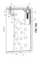
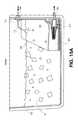
- FIGS. 14A-14Dillustrate a reservoir with a baffle and the variation of return flow at different flow rates for an inlet with a flow directing surface.
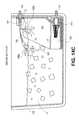
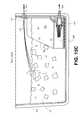
- FIGS. 15A-15Cillustrate a reservoir with a baffle and the variation of return flow at different flow rates for an inlet.
- FIGS. 16 and 17are section views of an inlet configured to provide a nozzle as well as a flow directing surface.
- FIG. 18illustrates a movable inlet configured with a variable flow directing surface.
- FIG. 19illustrates an exemplary actuator for use with a movable inlet.
- FIG. 20illustrates a movable inlet in a straight configuration with a bend configuration in phantom.
- FIG. 20Aillustrates a movable inlet with a tongue configured for movement by a shape memory alloy (SMA) element with a schematic representation of an exemplary SMA control system;
- SMAshape memory alloy
- FIG. 20Billustrates a movable inlet configured for configured for movement by a shape memory alloy (SMA) element with a schematic representation of an exemplary SMA control system.
- SMAshape memory alloy
- FIG. 20Cillustrates a movable inlet configured for configured for movement by a shape memory alloy (SMA) element wrapped about the inlet.
- SMAshape memory alloy
- FIG. 21Aillustrate an isometric view of a reservoir having a movable inlet used in conjunction with a baffle.
- FIG. 21Bis an enlarged view of the movable inlet of FIG. 21A .
- FIGS. 22A-22Cillustrate the operation of a control system having a reservoir with a baffle and movable inlet used in cooperation.
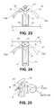
- FIGS. 23 and 24illustrate a movable inlet in different orientations with respect to a baffle.
- FIG. 25illustrates the movable inlet of FIG. 21B configured for operation with a motor M.
- FIG. 26illustrates the use of the movable inlet of FIG. 25 within a thermal therapy system.
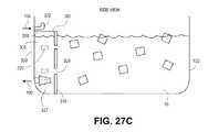
- FIGS. 27A , B and Cillustrate isometric, rear and side views of a multiple chamber baffle.
- FIG. 28Ais a top down view of a reservoir with a baffle and an an inlet displaced from the inlet associated with the baffle.
- FIG. 28Bis an end view of the reservoir in FIG. 28A showing the relative height and lateral separation of the inlets.
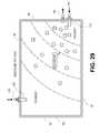
- FIG. 29is a top down view of a reservoir with an inlet on a wall different than the wall with the outlet.
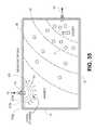
- FIGS. 30A , 30 B and 30 Cillustrate top down views of rectangular, round and polygonal shaped reservoirs, respectively, and the alternative inlet locations shown in phantom.
- FIG. 31is a top down view of a reservoir with an impeller.
- FIG. 32is a top down view of a reservoir having an air bubbler in communication with the reservoir to encourage fluid mixing.
- FIG. 33Ais a top down view of a reservoir with a diffuser.
- FIGS. 33B and 33Care section and isometric views of the diffuser of FIG. 33A .
- FIG. 34is a top down view of a reservoir with a diffuser with multiple walls.
- FIG. 35is a top down view of a reservoir with a diffuser with multiple screens.
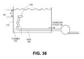
- FIG. 36illustrates a section view of a reservoir having a floating reservoir outlet tube in the reservoir.
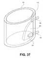
- FIG. 37is an isometric view of an oval shaped reservoir with a baffle and filter.
- FIG. 38is an isometric view of a baffle and filter cartridge.
- FIGS. 39 , 40 , and 41 A- 41 Dillustrate embodiments of a reservoir, baffle and filter assembly configured to be inserted inside a filter receptacle.
- FIGS. 42 , 43 A and 43 Billustrate a baffle in a reservoir ( FIG. 42 ), and isometric and end views of the baffle of FIG. 42 .
- FIGS. 43C and 43Dillustrate alternative openings in the baffle.
- FIGS. 44A , 44 B and 44 Cillustrate the operation of a therapy system having a baffle, two inlets and a diverter valve in different stages of operation and flow conditions.
- FIG. 45illustrates an embodiment of a temperature control system with a set point control system.
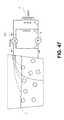
- FIG. 46illustrates a pump and two fluid paths configured to optimize flow though a wrap controlled with a bypass valve.
- FIG. 47illustrates fluid paths with a valve configured to optimize flow.
- the performance of the thermal therapy deviceis improved by adjusting the flow rate, the temperature and providing additional features to the thermal therapy device.
- the velocity of the fluidis proportional to the flow rate. The higher the fluid velocity, the further the return stream would fall from a reservoir inlet wall. The further the fluid falls from the reservoir inlet wall, the temperature of fluid proximal to the reservoir outlet decreases in temperature. Such a condition would be ideal for the coldest wrap temperature setting. Conversely, the lower the flow rate, the slower the fluid velocity and the closer the return fluid would fall to the reservoir inlet wall. In this condition, the inlet temperature to the pump would be warmer. This may require relatively slow flow rates in order for the return stream to fall close enough to the reservoir outlet to significantly affect outlet temperature. Low flow rates cause higher temperature deltas between the inlet and outlet of the wrap, which provides for uneven cooling of the mammalian body part.
- the temperature of the fluid leaving the wrapis warmther than the temperature of the fluid entering the wrap because the mammalian body is much warmther than the thermal fluid.
- the average wrap temperaturecould be defined as the average of the wrap inlet temperature and wrap outlet temperature.
- the difference between the wrap outlet temperature and the wrap inlet temperaturewill be referred to as “temperature delta” through the wrap. The temperature delta through the wrap depends on fluid flow rate, heat load, and the specific heat of the thermal fluid.
- the temperature deltaincreases as does the average wrap temperature. Therefore, to increase the desired average wrap temperature, the flow may be slowed sufficiently and a desired average wrap temperature may be achieved.
- the temperature leaving the thermal reservoiris often nearly freezing (assuming again that ice water is used as the thermal fluid). This results in near freezing fluid entering the wrap because the reservoir temperature is typically very even. In order for a warmer average wrap temperature to be achieved, substantially warmer fluid must leave the wrap.
- the temperature delta across the Wrapis 10° C., which is quite large. This may result in near freezing fluid entering the wrap which may be uncomfortable at best and, at worst, result in cold burns during extended periods of use.
- Performance of the thermal therapy deviceis improved using several methods. Pre-warming the water prior to entering the wrap is desirable.
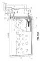
- FIG. 1illustrates an embodiment of a simplified thermal therapy system 1 .
- the thermal therapy systemcomprises a reservoir 2 , a wrap 3 , a pump 5 , a control system 7 and return system 9 .
- the arrowsindicate the fluid flow exiting/leaving the reservoir 2 into the wrap 3 as well as leaving the wrap 3 and entering the reservoir 2 .
- the system 1may be controlled manually by a user or simply operate in on/off modes. Alternatively, the system 1 may utilize a computer control system 7 monitors or regulates fluid flow through pump 5 and the wrap 3 .
- One or more sensorsmay monitor temperature, flow rate or other characteristics of the therapy system 1 .
- the sensor informationis then used by the control system 7 to operate components of the therapy system to produce the desired therapeutic result with the wrap 3 .
- the control system 7may be configured to regulating the return system 9 .
- the return system 9may be conduit used to return the heat transfer fluid in the system back to the reservoir 2 .
- the return system 9may include valves, diverters or other flow control elements (see e.g., FIGS. 44A-44C , 45 , 46 and 47 ).
- the reservoir 2may include one or more (i.e., multiple) reservoir inlets or reservoir outlets, a baffle, a filter, a diffuser or any of the reservoir improvements described herein.
- One method to improve the performance of the thermal therapy device 1is to encourage fluid leaving the reservoir outlet side of the reservoir 2 to have warmer temperatures when warmer wrap temperatures are desired. As a result, a high degree of thermal gradients across the reservoir are formed. When cold temperatures are desired, one would encourage the reservoir outlet side of the reservoir to have cold temperatures.
- One possible range of temperatures for these gradientsmay be between 0° C. and 15° C., with a preferred range between 0° C. and 10° C.
- reservoir fluid mixture temperatures mentioned belowmay also be in the ranges of 0° C. and 15° C. Other temperatures ranges may also be used.
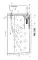
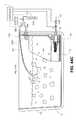
- FIG. 2illustrates isotherms 8 created in a conventional reservoir 2 .
- the top down view of FIG. 2illustrates reservoir 2 comprising a reservoir inlet 4 and reservoir outlet 6 .
- the warmer fluid from wrap 3enters through inlet 4 . Since at low pump speeds, the warmer water remains generally close to the inlet, isotherms 8 are produced in the reservoir fluid mixture 10 made of a fluid and ice.
- the isotherms 8are created as a result of warmer temperatures in different areas of the reservoir 2 .
- One shortcoming of the conventional reservoiris that as pump speeds increase, the warmer return water is sprayed farther into the reservoir and separated from the outlet. In addition, the increased velocity of the return flow may also cause circulation of the water and ice mixture and actually cause ice to circulate around within the reservoir or perhaps remain in proximity to the outlet thereby decreasing the reservoir temperature near the outlet.
- One method of creating isothermsis to provide proximal return streams where warm water is returned from the wrap 3 through the reservoir inlet 4 in close proximity to the reservoir outlet 6 while mitigating the unwanted effects described above.
- the various improvement described hereinprovide improvements and methods for achieving and maintaining the isotherms 8 closer to the reservoir outlet. The result is increased control over reservoir temperatures thereby enabling improved wrap temperature control.
- the bafflemay be a set of walls generally parallel and spaced close together that extend far enough into the ice bath so as to prevent ice from gathering too close to the reservoir outlet.
- the bafflemay be referred to as an ice baffle.
- the outlet temperature of the reservoir fluidcan be affected, thus affecting the internal wrap temperature in much the same manner.
- FIGS. 3A , 3 B, 3 C, 3 D, 3 E, 3 F and 3 Gillustrate top down views of a number of alternative baffle and reservoir embodiments.
- the reservoiris a container 52 with an interior 54 defined by a floor 53 and at least one wall.
- the outlet 104in fluid communication with the pump 5 .
- a baffleis created by a first wall and a second wall within the interior 54 . The first and second walls are spaced apart wider than the outlet 104 but narrower than the width of the interior adjacent the inlet 106 .
- the inlet 106 and/or the associated inletare placed in a location to that the inlet is above the surface of the heat transfer fluid when in use.
- the heat transfer fluid exiting the inlet 106enters the interior 54 —in some cases—above the surface of the heat transfer fluid within the container 52 .
- the inletmay be a movable inlet as described herein that is positioned to adjust between a position below the surface of the heat transfer fluid 10 and above the surface of the heat transfer surface 10 .
- FIG. 3Ais a top down view of a reservoir 50 a .
- the reservoir 50 ahas a container 52 made of a floor 53 and walls 62 , 64 , 66 and 68 .
- a baffle 58is formed by a wall 56 within the interior 54 and a portion of the wall 62 .
- the wall 56 and the portion of the wall 62are spaced apart by a width w wider than the outlet 104 but narrower than the width of the interior adjacent the inlet 106 .
- FIG. 3Bis a top down view of a reservoir 50 b .
- the reservoir 50 bhas a container 52 made of a floor 53 and walls 62 , 64 , 66 and 68 .
- a baffle 70is formed by a wall 71 and wall 72 within the interior 54 .
- the bafflemay be formed by attaching the walls 71 , 72 to the container interior or as a separate component (i.e., a standalone baffle) as described in the embodiments below.
- the walls 71 , 72are spaced apart by a width w that is wider than the outlet 104 but narrower than the width of the interior adjacent the inlet 106 .
- the walls 71 , 72are spaced narrower than the reservoir width.
- the baffleis narrower than the adjacent container wall.
- the baffle 70is narrower than the wall 68 .
- FIGS. 3C-3Gillustrate alternative reservoir configurations where the baffle is formed by or contained within a wall recess 75 .
- FIG. 3Cis a top down view of a reservoir 50 c .
- the reservoir 50 chas a container 52 made of a floor 53 and walls 62 , 64 , 66 and 68 .
- a recess 75 ais formed in wall 68 .
- the recess 75 amay be used to provide a baffle 70 .
- a baffle 70is formed by a wall 71 and wall 72 inserted into the recess 75 a .
- the bafflemay be formed by attaching the walls 71 , 72 to the recess 75 a interior.
- the baffle 70may be a separate component (i.e., a standalone baffle as described in the embodiments below) placed into the recess 75 a .
- the walls 71 , 72are spaced apart by a width w that is wider than the outlet 104 but narrower than the width of the interior adjacent the inlet 106 .
- the walls 71 , 72are spaced narrower than the reservoir width.
- the baffleis narrower than the adjacent container wall.
- the baffle 70is narrower than the wall 68 .
- FIG. 3Dis a top down view of a reservoir 50 d .
- the reservoir 50 dhas a container 52 made of a floor 53 and walls 62 , 64 , 66 and 68 .
- a recess 75 bis formed in wall 68 .
- the recess 75 bis narrower than the recess 75 a .
- the recess 75 bmay be used to provide a baffle 70 that is narrower than the baffle provided by recess 75 a .
- a baffle 70is formed by a wall 71 and wall 72 inserted into the recess 75 b .
- the bafflemay be formed by attaching the walls 71 , 72 to the recess 75 b interior.
- the baffle 70may be a separate component (i.e., a standalone baffle as described in the embodiments below) placed into the recess 75 b .
- the walls 71 , 72are spaced apart by a width w that is wider than the outlet 104 but narrower than the width of the interior adjacent the inlet 106 .
- the walls 71 , 72are spaced narrower than the reservoir width.
- the baffleis narrower than the adjacent container wall.
- the baffle 70is narrower than the wall 68 .
- FIG. 3Eis a top down view of a reservoir 50 e .
- the reservoir 50 ehas a container 52 made of a floor 53 and walls 62 , 64 , 66 and 68 .
- a recess 75 cis formed in wall 68 .
- the recess 75 cis narrower than the recess 75 b .
- the recess 75 cmay be used to provide a baffle 70 that is narrower than the baffle provided by recess 75 b .
- a baffle 70is formed by a wall 71 and wall 72 inserted into the recess 75 c .
- the bafflemay be formed by attaching the walls 71 , 72 to the recess 75 c interior.
- the baffle 70may be a separate component (i.e., a standalone baffle as described in the embodiments below) placed into the recess 75 c .
- the walls 71 , 72are spaced apart by a width w that is wider than the outlet 104 but narrower than the width of the interior adjacent the inlet 106 .
- the walls 71 , 72are spaced narrower than the reservoir width.
- the baffleis narrower than the adjacent container wall.
- the baffle 70is narrower than the wall 68 .
- FIG. 3Fis a top down view of a reservoir 50 f .
- the reservoir 50 fhas a container 52 made of a floor 53 and walls 62 , 64 , 66 and 68 .
- a recess 75 dis formed in wall 68 .
- the recess 75 dis narrower than the recess 75 c .
- the recess 75 dmay be used to provide a baffle 70 that is narrower than the baffle provided by recess 75 c .
- a baffle 70is formed by a wall 71 and wall 72 inserted into the recess 75 d .
- the bafflemay be formed by attaching the walls 71 , 72 to the recess 75 b interior.
- the baffle 70may be a separate component (i.e., a standalone baffle as described in the embodiments below) placed into the recess 75 d .
- the walls 71 , 72are spaced apart by a width that is wider than the outlet 104 but narrower than the width of the interior adjacent the inlet 106 .
- the walls 71 , 72are spaced narrower than the reservoir width.
- the baffleis narrower than the adjacent container wall.
- the baffle 70is narrower than the wall 68 .
- FIG. 3Gis a top down view of a reservoir 50 g .
- the reservoir 50 ghas a container 52 made of a floor 53 and walls 62 , 64 , 66 and 68 .
- a recess 75 eis formed between adjacent walls 62 , 68 .
- the recess 75 emay be used to provide a baffle 70 in a different orientation to the interior 54 .
- a baffle 70is formed by a wall 71 and wall 72 inserted into the recess 75 e .
- the bafflemay be formed by attaching the walls 71 , 72 to the recess 75 e interior.
- the baffle 70may be a separate component (i.e., a standalone baffle as described in the embodiments below) placed into the recess 75 e .
- the walls 71 , 72are spaced apart a distance w wider than the outlet 104 .
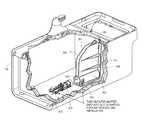
- FIGS. 4A and 4Bare isometric partial section views of a reservoir 300 with a baffle 302 disposed therein. Two alternatives of a baffle 302 are shown. Additional baffle alternatives are illustrated below.
- the baffle 302is comprised of two separated walls 301 and 303 .
- the baffle 302further comprises a filter access 308 at the bottom of the baffle 302 .
- the filter access 308is partially circular in shape to allow for easy access to the filter.
- a filtermay be placed into the access 308 or it may receive a filter cartridge as described below (see for example FIGS. 27C , 38 , 39 - 41 D).
- the bafflemay be just one wall as shown in FIG. 3A or 3 H.
- the baffle 302comprises a horizontal portion 305 , an angled portion 304 and a vertical portion 306 .
- the baffle 302comprises a horizontal portion 305 and angled portion 312 .
- the baffle 302 illustrated in FIG. 4Bis shaped such that the bottom edge is longer in length than the top edge which is closer to the reservoir inlet or nozzle 310 .
- the bafflemay comprise of compartments or chambers of different shapes and sizes so as to prevent ice from gathering too close to the reservoir outlet. (See e.g., FIGS. 27A-27C ).
- Another method to improve the performance of a thermal therapy system 1is to provide improvements or alterations in the manner or device used as an inlet to the reservoir.
- a conventional inletmay be used in combination with a baffle to achieve the reservoir performance improvements provided by the use of a baffle as described herein.
- the inletmay be modified in accordance with the alternatives that follow.
- Those improved inletsmay also be used in conjunction with a baffle.
- the inlet improvementsmay also be used in reservoirs without baffles.
- a number of inlet improvementsare described below including, for example: a flow modification feature or tongue (e.g., FIGS. 5-13 ), a movable inlet such as, for example, a pivoting inlet (e.g., FIGS.
- FIGS. 18 , 19 and 20a flexing or deflectable inlet
- an inlet configured as a nozzlee.g., FIGS. 16 , 17 , 28 A, 29 , and 32
- an inlet used in combination with a diffuserFIGS. 33A , 34 and 35 ).
- a flow directing elementmay be attached or coupled to the reservoir inlet or to provide an extension of a reservoir inlet.
- Embodiments of an inlet with a flow directing surface or tongueare illustrated in FIGS. 5-13 configured to optimize flow returning from the wrap 3 to the reservoir 2 .
- a tongue portion 22is connected to the body 153 .
- the tongue portion 22is configured to allow fluid leaving the front opening 28 to flow over and/or around the tongue portion 22 at low to medium flow rates, as illustrated by flow 108 in FIGS. 14A and 14B .
- flow 108 in FIGS. 14A and 14BAt medium high flow rates, as shown in FIG. 14C , a portion of the fluid flow 108 a remains over and/or around the tongue portion 22 and another portion of the fluid 108 a breaks free and projects beyond the tongue portion 22 .
- the fluidbreaks free and projects beyond the tongue portion 22 , as illustrated in FIG. 14D with the flow 108 .
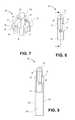
- FIGS. 5 and 6are isometric and cross section views, respectively of a flow directing inlet 150 .
- the flow directing inlet 150includes a body 153 .
- a tubular portion 20 within the body 155connects a back opening 52 with an opening or outlet 28 .
- the back opening 52is used to connect to the reservoir inlet 106 using any suitable means such as with a clamp, a barb fitting and the like.
- a tongue or flow directing surface 22extends from the outlet 28 in a curve arc as best seen in FIG. 6 .
- the tongueextends away from the outlet 28 and towards the reservoir floor.
- the length and shape of the tongue 22produce a lateral separation x and a vertical separation y from the outlet 28 to the distal end of the tongue.
- the lateral separation x and the vertical separation ymay vary depending upon a number of factors such as operating conditions in the system.
- the lateral separation xis typically about 2 cm and can range from about 0.5 cm to about 5 cm.
- the vertical separation yis typically about 3 cm and can range from about 0.5 cm to the height of the reservoir.
- the top surface of the tongue 22includes an elevated portion or ridge 40 .
- the ridge or elevated portion 40is aligned with the outlet 28 .
- the various embodiments of the flow directing inletmay be used alone or in conjunction with a baffle, as illustrated in FIGS. 4A and 4B .
- the length, overall shape and contour (i.e., ridge 40 ) of the tongue 22are selected to interact with the flow exiting outlet 28 .
- flow through the inlet 150passes along the tubular portion 20 and out the front opening of outlet 28 .
- the flowwill either run along all or part of the length of the tongue or flow directing surface 22 .
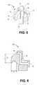
- FIGS. 7 and 8are isometric and end views, respectively of a flow directing inlet 155 .
- the flow directing inlet 155is similarly constructed to the flow directing inlet 150 .
- a tongue or flow directing surface 22extends from the outlet 28 in a curve as best seen in FIG. 7 .
- the tongueextends away from the outlet 28 and towards the reservoir floor.
- the length and shape of the tongue 22produce a lateral separation from the outlet 28 to the distal end of the tongue.
- the top surface of the tongue 22includes an elevated portion or ridge 40 . In one aspect, the ridge or elevated portion 40 is aligned with the outlet 28 .
- the flow directing inlet 155includes a transition area or surface 42 extending from one side of the tongue 22 towards a directing structure 24 .
- the length, overall shape and contour (i.e., ridge 40 ) of the tongue 22are selected to interact with the flow exiting outlet 28 .
- flow through the inlet 155passes along the tubular portion 20 within body 153 and out the front opening or outlet 28 .
- the flowwill either run along all or part of the length of the tongue or flow directing surface 22 .
- Some of the flow falling away from the elevated portion 40will flow onto the transition area 42 .
- the transition area 42is sloped towards the directing structure 24 .
- the directing structure 24is bell-shaped structure positioned to direct the flow onto an adjacent baffle wall. As illustrated in FIG. 9 , the directing structure 24 directs flow onto the interior of baffle wall 301 . While described as two parts, it is to be appreciated that the tongue, transition structure and directing structure may be formed integrally and with other shapes suited to directing flow from the tongue to a baffle wall.
- the tonguemay be of any shape, size or material configured to optimize flow returning from the wrap to the reservoir.
- the directing surface or tonguemay have other shapes, sizes and components such that at low and medium flow rates, the surface tension acting between the surface and in the flow from the inlet directs the fluid downwards towards the reservoir inlet. At higher flow rates, the velocity is high enough such that the return fluid breaks free of the directing surface and projects far away from the reservoir inlet and the reservoir outlet.
- the nozzleallows return fluid to land proximal to the reservoir outlet in low and medium flow rates, and far from the reservoir outlet at higher flow rates.
- the surface tension of the return fluidallows the fluid to flow across a properly engineered surface of the nozzle.
- the ranges for flow ratesmay be between 50 ml per minute and 1.5 liter per minute.
- a preferable rangemay be from 150 ml per minute to 550 ml per minute.
- One possible range for low flow ratemay be 150 ml per minute to 249 ml/minute, for medium flow rate may be 250-350 ml/min and for high flow rate may be 351 ml per minute to 550 ml per minute. Other ranges may be desirable as well.
- the tonguemay be modified to further alter the interaction with the flow from the outlet 28 .
- FIGS. 10-13These alternatives are illustrated in FIGS. 10-13 .
- the modified flow inletis positioned between the walls 301 , 303 of a baffle 302 . While illustrated as modifications of the flow directing inlet 155 with both a transition area 40 and flow directing structure 24 , the modifications are not so limited. The modifications described in FIGS. 10-13 are also applicable to the flow directing inlet 150 illustrated in FIGS. 5 and 6 .
- FIGS. 10-13each illustrate an alteration to the tongue 22 . Specifically, the upper surface of the tongue 22 is modified from that of inlets 150 , 155 .
- the upper ridge or elevation 70moves from a centerline position near outlet 28 towards one side as it traverses towards the tongue distal end. In this manner, the angled ridge 70 will direct flow towards the wall 301 .
- the angled ridge 70acts in furtherance of the purpose of transition area 42 and directing structure 24 . While illustrated with the transition area 42 and the directing structure 24 , the angled ridge 70 may be used without those additional structures.
- the upper surface of the tongueincludes a groove or recess 72 along the centerline position near outlet 28 and extending towards the tongue distal end.
- the depth of the recess 72 and its general concave shape near the centerlinepermit the tongue upper surface to maintain a generally convex cross section. While illustrated as straight along the surface, the recess 72 may be angled as with angled ridge 70 to direct flow towards the wall 301 . While illustrated with the transition area 42 and the directing structure 24 , the recess 72 may be used without those additional structures.
- the upper surface of the tongueis shaped as an u-shaped groove or recess 74 along the centerline position near outlet 28 and extending towards the tongue distal end.
- the depth of the recess 74alters the cross section of the tongue to have an overall concave shape. While illustrated as straight along the surface, the recess 74 may be angled as with angled ridge 70 to direct flow towards the wall 301 . While illustrated with the transition area 42 and the directing structure 24 , the recess 74 may be used without those additional structures.
- the upper surface of the tongueis shaped as a v-shaped groove or recess 76 along the centerline position near outlet 28 and extending towards the tongue distal end.
- the depth of the recess 76alters the cross section of the tongue to have an overall v-shape. While illustrated as straight along the surface, the recess 76 may be angled as with angled ridge 70 to direct flow towards the wall 301 . While illustrated with the transition area 42 and the directing structure 24 , the recess 76 may be used without those additional structures.
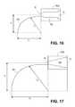
- FIGS. 16 and 17illustrate alterations to the body 153 and the tongue 22 .
- the tubular portions 20 a and 20 bhaving variable bore diameters.
- the flow paths 20 a , 20 bplace the outlet 28 in a more direct path with the opening 52 (in contrast to the rise found in tubing 20 of FIG. 6 ).
- both tubular portions 20 a , 20 bhave reduced diameters so that outlet 28 is now a nozzle outlet.
- the bodies 153 a , 153 b illustrated in FIGS. 16 and 17may be used as inlets only—without the tongue portion 22 . In other words, the body 153 a in FIG.
- the body 153 b in FIG. 17may be fabricated without a tongue 22 so that only the body 153 a with outlet 28 is connected to a reservoir.
- FIGS. 16 and 17also illustrate the additional variation possible with the tongue 22 to influence a wide range of fluid flows.
- the tongue 22has a horizontal displacement (x) extending from the outlet 28 towards the reservoir interior—in general terms towards an opposite wall in the reservoir.
- the tongue 22has a vertical displacement (y) extending from the outlet 28 towards the reservoir floor or bottom—in general terms towards the reservoir outlet.
- Tongues 22 a and 22 bboth follow generally curved shapes. While not exactly circular, the tongue shape may be approximated as a section of a circle with a radius r.
- FIG. 16shows how the displacement x 1 , y 1 produces a shorter radius tongue 22 a of radius r 1 .
- the flow from outlet 28will be directed nearly directly beneath the outlet 28 as a result of the small horizontal displacement x 1 .
- a short radius r 1will likely only influence slower flow rates.
- the flowwill likely separate from the tongue 22 a and be directed more generally into the interior.
- FIG. 17shows how the displacement x 2 , y 2 produces a longer radius tongue 22 b of radius r 2 .
- the flow from outlet 28will be directed towards an area at some distance from the outlet 28 as a result of the larger horizontal displacement x 2 .
- a long radius r 2will likely influence a wider range of fluid flow rates.
- the flowwill likely remain on the tongue 22 b and directed generally towards the inlet. It is not until the flow rate increases more that the flow will separate from tongue 22 b and be directed more generally into the interior.
- the diameter of the front opening 28may be adjusted in conjunction with the shape of the tongue portion 22 to effect performance of the nozzle 80 . With the larger diameter of the front opening 28 , the return fluid flow rate must be higher before the return stream begins to break away from the nozzle 80 . Conversely, with a smaller diameter of the front opening 28 , the return steam will break away from the nozzle at a lower flow rates.
- the opening 52may be placed over a barbed tube fitting or otherwise secured to and/or threaded in the reservoir wall.
- the reservoir 102includes an inlet 106 , an outlet 104 and a baffle 302 and is shown in section view.
- the baffle 302includes a filter opening 308 containing a filter cartridge 910 over the outlet 104 .
- the wall 303is visible in this view.
- the inlet 106is connected to an inlet tube 110 .
- the inlet 106is in communication with a fluid directed surface inlet 150 aligning the opening 28 with a directed surface or tongue 22 .
- FIGS. 14A-D and 15 A-Cillustrate return flow paths to the reservoir 102 at different flow rates.
- the reservoir 102contains a heat exchange mixture 10 .
- the heat transfer mixtureis water and ice.
- the inlet 106penetrates the reservoir wall above the level of the heat transfer mixture. Both the outlet 28 and the outlet of the inlet tube 110 are positioned above the level of the heat transfer mixture 10 .
- the reservoir 102is shown in section view.
- the reservoir 102also contains a baffle 302 , but in this view, only the wall 303 of the baffle is visible.
- the bafflealso includes the filter channel 308 containing filter cartridge assembly 910 over the reservoir outlet 104 .
- the heat exchange mixture 10 fluidflows from the reservoir inlet 106 to an inlet tube 110 in FIGS. 15A-C .
- the heat exchange mixture 10 fluidflows from the reservoir inlet 106 to an fluid directing inlet 150 with a flow directed surface or tongue 22 as shown in FIGS. 14A-14D .
- the flow rate of the return fluid 108is shown exiting the reservoir inlet 106 through outlet 28 of the directed flow surface inlet 150 .
- the directing surface or tongue 22is shaped such that at low fluid flow rates, the fluid 108 runs over and around the tongue 22 and directed downwards towards the reservoir outlet 104 by both gravitational and surface tension forces.
- the tongue 22assists in directing the flow 108 nearly directly downward towards the inlet at the bottom of baffle 302 .
- the return fluid 112flows out of pipe inlet 110 and is flows out of the reservoir outlet 104 and is directed downwards by only gravitational forces. While the flow 112 is also downward directed, it has a less direct flow towards the bottom of the baffle.
- the flow 112is still between the baffle walls but is closer to flowing beyond the forward edge of the baffle wall (i.e., the edge furthest into the reservoir interior) than the flow 108 .
- return fluid 108exits the reservoir inlet 106 through outlet 28 of the directed flow surface inlet 150 .
- the shape of tongue 22is such that even at medium fluid flow rates, the surface tension between the return fluid 108 and the tongue 22 maintains control of the direction of flow 108 .
- the flow 108is directed downwards towards the reservoir outlet 104 .
- the return fluid 112 the return fluid 112flows out of pipe inlet 110 and is flows out of the reservoir outlet 104 and is directed downwards by only gravitational forces.
- the flow 112is now less downwardly directed; it has a less direct flow towards the bottom of the baffle.
- the flow 112is now beyond the baffle walls and entering the reservoir interior more towards the middle as opposed to the downwardly directed flow 108 in FIG. 14B .
- the increased fluid flow rateis beginning to overcome the surface tension between the fluid and the tongue 22 .
- the fluid flow 108is separating reflecting the decreasing influence of the tongue 22 at higher flow rates.
- a fluid flow portion 108 ais projected further from the outlet 28 and beyond the baffle wall.
- the fluid flow 108 areflects that portion of the flow 108 that is free from the surface tension of tongue 22 .
- Another fluid portion 108 bmaintains under the influence of the surface tension of tongue 22 .
- the fluid flow 108 bremains directed downwards towards the reservoir outlet 104 and the bottom of the baffle 302 .
- Another method to improve the performance of the thermal therapy deviceprovides return stream vector control with a moving or movable inlet for directing the return stream within the reservoir interior.
- a movable inletmay direct the return flow in the direction of the reservoir outlet in order to keep the return fluid proximal to the reservoir outlet.
- the warmer return waterlands closer to the reservoir outlet, the water surrounding the reservoir outlet is warmed.
- the fluid flow ratemay not need to be reduced. Instead, temperature control adjustments may be provided by adjusting the direction, orientation or attitude of the incoming fluid by moving the movable inlet to change the direction of the return stream.
- the return stream vector control enabled by the moving inletis used to create temperature gradient/isotherms in the reservoir.
- the motion of a movable inletmay be provided in a number of different configurations including mechanical structures that provide movement such as pivoting structures, rotating structures, twisting structures and/or bending structures.
- the inletmay be activated by physically changing conditions or further may be mechanically or electrically activated. Alteration of the tongue or deflection of an inlet may be accomplished by a number of different configurations either directly by the user or by a controller executing instructions or based on input from a user.
- a suitable actuatormay be positioned alongside, on, within or in any other suitable orientation to cause deflection or controlled movement of the tongue or the inlet by the actuator. The deflection or movement of a tongue or inlet may be towards or away from a component in a reservoir or a portion of a reservoir.
- the inletmay be moved by deflecting or manipulating all or part of the inlet in order to impart the desired directionality of the return flow from the inlet relative to the reservoir interior and/or components within the reservoir interior.
- inlet moving structuresinclude linkages, rods, lines or other connectors attached between the proximal and distal ends of the inlet whereby the degree of movement of the linkage, rod, line or connector determines the amount of inlet flexion, bend or directionality imparted to the inlet.
- the degree of inlet movement or deflection in a movable inletis provided a suitably positioned actuator.
- An actuatorincludes any of a magnetic, electrical, electro active, mechanically or pneumatically operated structure positioned to interact with the inlet to provide the desired flexion or movement of the opening 28 relative to the reservoir interior or a structure within the reservoir interior.
- the actuatormay include a shape memory alloy structure positioned relative to the inlet whereby the degree of activation of the shape memory alloy structure corresponds to the amount of inlet flexion, bend or directionality imparted to the inlet.
- moving inletsmay be used in combination with biasing structures.
- the biasing structuremay be used to align the inlet with a preferred inlet direction. Actuation of the inlet movement device, structure or mechanism would then be used to overcome the bias condition and deflect the moving inlet. Once the movement device, structure or mechanism is removed, the bias would return the inlet to the preferred inlet direction.
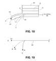
- FIG. 18is a section view of an inlet 250 ′ having a tongue 222 positioned adjacent the opening 28 .
- An actuator 290extends within the tongue 222 to a connection point 294 near the distal end.
- the tongueassumed a rest state A.
- the actuator 290is engaged or actuated, the tongue 222 deflects into state B.
- a control 296is provided proximal to the inlet 250 ′ and is connected to a controller or for use by a user.
- the actuator 290is a wire connected at 294 to the tongue 222 .
- the control 296is a knob or handle.
- the actuator 290is a shape memory actuator (SMA) and the control 296 is a suitable electronic control and power system used for the controlled actuation of SMA.
- the SMA actuator 290has a biased, inactive condition shown in condition A. As the SMA is actuated and it begins to deflect, it may curve into the bend shown in state B or be nearly downward in state C.
- the tongue 222when the actuator 290 is an SMA actuator, then the tongue could be altered by actuation of the SMA from a resting configuration (state A) to various bent configurations, for example states B and C. It is to be appreciated that the bias condition could be reversed such that the tongue 222 remains in state C when the SMA actuator 290 is inactive and actuation of the SMA actuator 290 produces states B and C.
- FIG. 20illustrated an inlet tube 110 connected to an actuator 290 .
- the actuator 290is connected near the distal end at point 294 .
- the inlet tube 110is in a generally straight configuration as illustrated by state A.
- the actuator 290is active, the tip of inlet 110 or the opening 28 is aligned downwardly as indicated in state B (in phantom).
- the actuator 290is a pull wire.
- Other types of actuatorsmay be used to deflect, bend or alter the position of an inlet in the systems described herein. The manner of actuation may depend upon the type of actuator 290 selected. Appropriate user interfaces, input devices, controls, power supplies and electronic support are provided to operate an actuator as described herein.
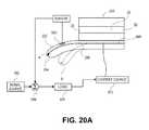
- the actuator 290 extending through tongue 222comprises a shape memory alloy element 868 extending along the length of the actuator 290 .
- Actuation (i.e. controlled deflection) of the actuator 290can be controlled by the amount of electric current applied to the shape memory element 868 .
- the shape memory alloyAs electrical current is applied to the shape memory element 868 , the shape memory alloy is heated above its activation temperature, allowing it to move towards its previously memorized shape. When the electrical current is removed, the shape memory alloy is cooled, preventing further movement of the actuator 290 .
- an electrical current source 892can be is coupled to the shape memory element 868 to selectively supply electrical current thereto.
- a control systemcan be configured to vary the amount of current supplied to the actuator, which will in turn vary the degree to which the actuator changes shape and thus the degree to which the tongue 222 is bent or deflected.
- a feedback control systemcan optionally be included to control the bending of the tongue 222 .
- a strain gauge 880can be located on the tongue 222 .
- a sensor circuit 884can produce a signal whose magnitude is indicative of the strain to which the tongue 222 is subjected, and this signal can be supplied to a summoning circuit 888 .
- a signal source 892can also supply a signal to the summoning circuit 888 in which the signal's value represent a degree of bending desired for the tongue 222 .
- the summing circuit 888can effectively compare the two input signals and, if there is a difference, signal the logic circuit 876 as to the amount of this difference.
- the logic circuit 876can, in turn, signal the current source 872 to cause further bending (or unbending) of the tongue 222 so that the output signal of the sensor 884 will move closer in value to the signal supplied by the signal source 892 .
- This feedback control systemcan ensure that the tongue 222 is bent as desired.
- a feedback circuit for a bending actuatoris described further in U.S. Pat. No. 5,933,002, which is hereby incorporated by reference. In particular, the feedback system described by FIGS. 6 and 8 of U.S. Pat. No. 5,933,002 could be included as part of the actuator 290 described herein.
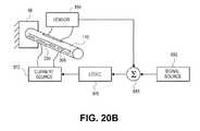
- the actuator 290 extending along the inlet 110can, similar to the embodiment of FIG. 20A , include a shape memory element 868 and/or a feedback control system.
- the shape memory element 868can cause actuation of the actuator 290 to controllably bend the inlet 110 .
- the feedback control systemcan be used to ensure that the desired amount of bending is obtained.
- the shape memory element 868need not be linearly aligned with the inlet 110 or the tongue 222 . Rather, the shape memory element 868 could be aligned off-axis or helically wound to allow the tongue 222 or inlet 110 to bend in different directions. For example, referring to FIG. 20C , the shape memory element 868 could be helically wound around the inlet 110 . Supplying current to the helical shape memory element 868 of FIG. 20C can selectively cause a change in shape of the shape memory element to thereby cause a twisting of the inlet 110 in the direction indicated by the arrow 940 .
- the shape memory element 868 of the various embodiments described hereincould include a plurality of shape memory portions allowing the tongue 222 or inlet 110 to move in a variety of directions. Further, the shape memory element 868 can include a pair of antagonistic shape memory portions to allow the inlet 110 or tongue 222 to be controllably moved in one direction and in the opposite direction. Antagonistic shape memory elements are described further in U.S. Patent Publication No. 2003/0199818, which is hereby incorporated by reference. In particular, the first and second actuator members 52, 54 shown in FIG. 1 of U.S. Patent Publication No. 2003/0199818 could be included as part of the shape memory element 868 described herein.
- FIGS. 21A and 21Billustrate an embodiment of a moving inlet 202 in a reservoir 102 .
- the moving inlet 202includes a pivoting structure 214 .
- the moving inlet 202directs fluid flow from the reservoir inlet 106 via opening 28 into the reservoir 102 .
- the reservoir inlet 106is connected to the moving inlet 202 via pivoting structure 214 .
- the pivoting structure 214may be a sealed swivel hinge connection or another type of connection configured to allow movement of the moving inlet 202 .
- the moving inlet 202may pivot, rotate or move in any direction by altering the location of the pivoting structure 214 and its relationship to the inlet 202 , the reservoir 102 or a structure within the reservoir 102 , such as a baffle.
- the moving inlet 202pivots from a horizontal position 211 generally along longitudinal axis to downwardly directed positions 212 , 213 .
- a rotation mechanismhere a knob 204 , is provided to adjust the deflection amount of moving inlet 202 .
- the rotation mechanism 204is connected to the pivoting structure 214 using shaft 217 or other suitable connector.
- FIGS. 22A-22Cillustrate embodiments of the return stream vector control with the moving inlet 202 shown in FIG. 21B in the context of a reservoir 102 .
- FIG. 22Aillustrates warmer water returning from the wrap 230 through the moving return 202 in position 213 .
- the return flow 208 cis directed downward towards the bottom of baffle 302 and the outlet 104 .
- FIG. 22Billustrates the moving inlet 202 position in flow position 212 .
- the return flow 208 bis directed towards the outer walls of the baffle towards the more central portion of reservoir 102 .
- FIG. 22Cillustrates the moving inlet 202 in flow position 211 .
- FIGS. 22A-22Cillustrate one aspect of moving that is by the pivoting of the moving inlet 202 as indicated in the various positions 211 , 212 and 213 .
- FIGS. 21A , 21 B and 22 A-Cillustrate a configuration of the pivoting structure 214 that permits the moving inlet 202 to be deflected in a manner that maintains the return flow in the region of the reservoir generally between the baffle walls 301 , 303 .
- Other orientationsare possible for the moving inlet to introduce the return flow into other positions.
- FIG. 23illustrates a view towards reservoir wall 68 and shows the alignment of the rotating structure 214 and moving inlet 202 relative to the top of baffle walls 301 , 303 .
- operation of the rotating structure 214causes the movable inlet 202 to direct outlet 28 to the side of wall 301 to produce directed flow 218 a .
- the inlet 202may be positioned between the walls 301 , 303 to produce directed flow 218 b .
- the inlet 202may be positioned to the side of wall 303 to produce directed flow 218 c . While moving relative to the baffles walls, the moving inlet 202 remains a generally downward directing orientation.
- FIG. 24illustrates a top down view towards a reservoir floor 53 of the movable inlet 202 .
- the view of FIG. 24shows the alignment of the rotating structure 214 and moving inlet 202 in a position above the top of baffle walls 301 , 303 .
- operation of the rotating structure 214causes the movable inlet 202 to direct outlet 28 to the side of wall 301 to produce directed flow 219 a .
- the inlet 202may be positioned between the walls 301 , 303 to produce directed flow 219 b .
- the inlet 202may be positioned to the side of wall 303 to produce directed flow 219 c.
- FIG. 25illustrates a moving inlet 202 connected to a motor M via shaft 217 .
- the motor Mis connected to a suitable source of power.
- the motor Mis in communication with a suitable controller.
- the controller for motor Mmay be a simple resistive dial.
- the dialmay be labeled with an indicator showing inlet direction or angle of inlet deflection.
- the motor Mis connected to a controller such as the controller 7 of the other all system. In this case, the controller will adjust the degree of inlet deflection as part of an overall system control scheme.
- FIG. 26illustrates one exemplary thermal control system having a motor M configured to alter the position of a movable inlet 202 .
- the control systemhas a fluid circuit with a pump 232 , wrap 230 , reservoir 102 , thermocouples T 1 , T 2 and a movable inlet 214 driven by a motor M.
- the controller 7receives inputs such as a temperature set point or other operational requirements along with information from sensors such as thermocouples T 1 and T 2 and produces outputs to control the operation of the pump 232 and the movable inlet 202 via the motor M.
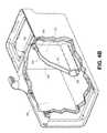
- FIGS. 27A-Cillustrate isometric, end and side views, respectively, of an embodiment of a multi-chamber baffle 300 in reservoir 102 .
- the multi-chamber baffle 300includes a chamber 305 formed by one or more outer walls 310 that separate the baffle chamber 305 from the reservoir interior.
- One or more dividing walls 303may be used to partition the baffle chamber 305 .
- three dividing walls 303are provided to create chambers 305 a , 305 b , 305 c , and 305 d .
- One or more openings 320may be formed in the outer walls 310 and/or dividers 303 .
- openings 320 of equal sizeare shown in the outer walls 310 for each of the chambers 305 a - 305 d , more or fewer openings as well as different shape and size openings may be used. Similarly, while only two rectangular openings 320 of equal size are shown in the dividing walls 303 , more or fewer openings as well as different shape and spacing of openings 320 may be used in the dividing walls 303 .
- multi-chamber baffle 300is generally rectangular.
- One or more walls 310may be used to form other baffle shapes.
- a single wall 310may be curved about the inlet and outlet and attached to the same reservoir interior wall such that the baffle chamber 305 is formed from a single wall 310 in a generally curved shape.
- a baffle wall 310may extend between two reservoir walls and an included corner to form a baffle chamber 305 of a generally triangular shape.
- baffle 300position within the reservoir on one side of the reservoir interior with the inlet and outlet along one side in the same chamber, here chamber 305 a .
- Other inlet 302 positionsare possible above any of the other chambers 305 b , 305 c or 305 d .
- the baffle 300may be configured and positioned such that the inlet, and/or outlet are in different chambers by inserting addition dividing walls 303 .
- Dividing wallsare shown in a vertical orientation.
- Dividing walls 303may be in horizontal orientations as well as angled orientations (i.e., orientations between vertical and horizontal orientations).
- the inlet 302 of multi-chamber baffle 300may be a fixed inlet or a moving inlet.
- the inlet 302is positioned within the chamber 305 at an inclined angle as best seen in FIG. 27B .
- the inclined angleis selected so that as flow speed changes, the fluid exiting opening 28 will be directed to various locations within the baffle chamber 305 . In general, at slower flow speeds, the fluid leaving opening 28 remains closer to inlet 302 . At higher flow speeds, the fluid leaves opening 28 and enters the chamber 305 at a greater distance from the inlet 302 in general proportion to the fluid speed.
- FIG. 27BThe interaction of flow speed and discharge from inlet 302 is best seen in FIG. 27B .
- the fluidleaves opening 28 and follows fluid flow return path 359 into chamber 305 a .
- the fluidleaves opening 28 and follows fluid flow return path 357 into chamber 305 b .
- the fluidleaves opening 28 and follows fluid flow return path 355 into chamber 305 c .
- the fluidleaves opening 28 and follows fluid flow return path 354 into chamber 305 d .
- the inlet 302is positioned within the chamber 305 as described above.
- the moving inlet 302includes a flex, joint, coupling or pivot to provide a change in the angle shown in FIG. 27B .
- the moving inlet 302may be manipulated as with other moving inlet embodiments described herein to direct return flow to different portions of a multiple chamber baffle 300 .
- the orientation, movement and control of the moving inlet 302may be configured as described herein, by way of non-limiting examples, the configurations shown and described in FIGS. 18-20 , 21 A, 21 B, 22 A- 22 C, 23 and 24 .
- the inclined angle of the moving inlet 302is selected to complement or counteract the flow stream changes produced by changes in flow speed. As a result, changes in return flow direction as a result of flow speed changes as discussed above may be augmented or mitigated my adjusting the relationship of the moving inlet 302 to the baffle chamber 305 .
- Another method to improve the performance of a thermal therapy deviceis to provide robust mixing methods for cold temperatures. For instance, assuming ice fluid 10 is used in the reservoir 102 , the reservoir temperature would be nearly 0° C. If the reservoir was well mixed with the warmer return fluid from the wrap 3 , the reservoir outlet temperature would remain nearly 0° C. This would be ideal if the coldest possible wrap temperature is desired.
- One exemplary mixing methodincludes adjusting the return flow stream to push ice towards reservoir outlet 106 .
- the return streammay be directed in a number of different ways as further described in the embodiments that follow.
- FIGS. 28A and 28Billustrate top down and partial end views, respectively, of a two inlet system.
- two inletsare provided in different positions along the same wall, here reservoir wall 68 .
- the two inletsare separated laterally (as shown in FIG. 28A ) and are spaced about equally above the floor 53 (see FIG. 28B ).
- the relative positions of the two or more inletsmay be selected to create, alter or enhance a flow pattern or current within a reservoir interior.
- a first inletis provided by an inlet 150 within a baffle 302 as described above.
- a second inlet 420is provided as shown in a position laterally separated from the first inlet.
- the relative position of the openings 28 along wall 68is best seen in FIG. 28B .
- the inlet 420may be configured as a nozzle (i.e., reduced diameter within the inlet 420 directed towards the opening 28 , see e.g., FIGS. 16 and 17 ). It is to be appreciated that any of the inlets embodiments described herein may be used to as the first inlet, second inlet or other inlets in a multiple inlet configuration.
- the resulting fluid stream 425produces current 424 and the ice in the fluid mixture 10 to be pushed towards reservoir outlet within baffle 300 .
- the return stream 425 from the wrap 3may cause turbulence and mixing of the water of different temperatures.
- the return stream 425may be a high velocity return stream (in the case of nozzle shown in FIG. 28A ) in order to enhance the amount of turbulence created in the fluid mixture 10 .
- One or more valvesmay be provided to adjust the amount of flow divided between the first inlet and the second inlet or alternatively to direct return flow to one of the first inlet or second inlet.
- the one or more valvesmay be under the manual control of a user or under the control of a system controller as described elsewhere in this application.
- FIG. 29An alternative multiple inlet configuration is illustrated in FIG. 29 .
- the first inletis provided by the inlet tube 110 .
- the inlet tube 110connects the inlet 106 via reservoir wall 68 and is placed adjacent outlet 104 near where reservoir walls 68 , 62 meet.
- the second inlet 410is connected to nozzle inlet 420 though reservoir wall 66 near where walls 66 , 64 meet.
- One or more valvesmay be provided to adjust the amount of flow divided between the first inlet and the second inlet or alternatively to direct return flow to one of the first inlet or second inlet.
- the one or more valvesmay be under the manual control or a user or under the control of a system controller as described elsewhere in this application. While illustrated without a baffle, a baffle may be used in conjunction with a multiple inlet system configuration.
- the resulting fluid streamproduces current within the reservoir and the ice in the fluid mixture 10 to be pushed towards reservoir outlet 104 .
- the return streammay cause turbulence and mixing of the water of different temperatures.
- the return stream produced in the configuration of FIG. 29may be a high velocity return stream (in the case of nozzle shown in FIG. 29 ) in order to enhance the amount of turbulence created in the fluid mixture 10 .
- FIG. 30Ais a top down view of a rectangular reservoir 102 having walls 68 , 62 , 64 and 66 .
- An outlet 104is shown in wall 68 about midway between walls 66 and 62 .
- Additional inlet locations 420are shown in phantom. Inlet locations 420 may be used to exemplify inlet locations for embodiments having one inlet, two inlets or multiple inlets.
- the rectangular reservoir 102 in FIG. 30Ashows additional inlet locations 420 a , 420 b and 420 c are along wall 66 .
- Additional inlet locations 420 d and 420 eare shown along wall 64 .
- Additional inlet locations 420 f , 420 g and 420 hare shown along wall 62 .
- the dashed line 425 in FIGS. 30A , 30 B and 30 Cindicates a division of the reservoir interior into adjacent 425 a and forward 425 b portions.
- the location of an inletmay be described as being adjacent or forward of the outlet.
- all alternative inlets 420 a - 420 gare shown in positions forward of outlet 104 .
- FIG. 28Aillustrates a two inlet embodiment where the second inlet 420 is placed in an adjacent position relative to the outlet 104 .
- a reservoir 102may have a shape other than rectangular.
- FIG. 30Bis a top down view of an oval reservoir 102 with a wall 68 .
- An outlet 104is shown in wall 68 within the portion 425 a .
- Additional inlet locations 420 a - 420 gare shown in phantom about the perimeter of the wall 68 .
- a reservoirmay have a polygon shape or non-geometric shape.
- FIG. 30Cis a top down view of a polygonal, non-rectangular reservoir 102 .
- the non-rectangular polygonis an octagon.
- the reservoir 102 in FIG. 30Chas walls 67 , 68 , 62 , 63 , 64 , 65 and 66 .
- An outlet 104is shown in wall 68 about midway between walls 61 and 67 .
- Additional inlet locations 420are shown in phantom. Inlet locations 420 may be used to exemplify inlet locations for embodiments having one inlet, two inlets or multiple inlets.
- 30Cshows additional inlet locations of: 420 a in wall 67 , 420 b in wall 66 , 420 c in wall 65 , 420 d in wall 64 , 420 e in wall 63 , 420 f in wall 62 and 420 g in wall 61 .
- a mixing methodcomprises an agitator, impeller or other stirring implement to stir the reservoir fluid 10 .
- a reservoir 102includes an inlet 106 connected to a nozzle inlet 420 and an outlet 104 .
- An impeller 445is connected to movement mechanism 440 via a shaft 441 .
- a suitable seal or bearingis provided on shaft 441 where it penetrates the reservoir wall. In operation, the impeller 445 mixes the reservoir fluid 10 .
- the orientation of the impeller 445 within the reservoir 102may be fixed as shown, or variable.
- a coupling(not shown) may be provided enabling the impeller 445 to be flexed, rotated or pivoted in any direction within the reservoir.
- the shaft 441may be a flexible shaft that may be use to insert or withdraw the impeller 445 relative to the reservoir interior.
- the movement mechanism 440 and the coupling(if provided) may be operated manually or driven by any suitable electrical or mechanical device suited to mixing the reservoir fluid 10 .
- the operation of the impeller 445including, for example, rotation, insertion, withdrawal or variable orientation of the impeller, may be under control of the user or as system controller as described herein.
- the impeller 445may be placed in a number of different locations around the reservoir wall as well as used in conjunction with different reservoir shapes. As such, the impeller may be placed as discussed above in the alternative positions and reservoir shapes of FIGS. 30A-30C or along the reservoir floor 53 . Additionally, the impeller may be positioned in a wall in any of a wide variety of distances from the floor 53 depending upon the desired mixing result.
- a mixing method techniquemay include injecting air into the reservoir 102 to encourage mixing of the reservoir fluid 10 .
- FIG. 32is a side view of a reservoir 102 having an inlet 106 connected to an inlet tube 420 and an outlet 104 with a filter 910 .
- An aperture 442is provided in reservoir floor 53 adjacent an outlet 104 .
- a source of air or air bubblerprovides an air flow 450 through tubing 444 and aperture 442 .
- Air exiting aperture 442produces bubbles 448 injected upwards within the reservoir fluid 10 .
- the bubble actioninteracts with the return fluid flowing from the reservoir inlet 106 via tubing 420 and flowing out from reservoir outlet 104 to produce mixing 446 indicated by the arrows with in fluid 10 .
- the source of aircould be a dedicated air source.
- the source of aircold be a return air flow from the wrap where the wrap includes an air bladder or compressive capability.
- the air sourcecould also be an air source or pump included in the system to provide air for the operation of the wrap.
- Another method to alter the performance characteristics of a thermal therapy system 1is to return fluid far away from the reservoir outlet 104 when cold temperatures are desired.
- Techniques such a separating the inlet from the outletdescribes above or use of moving inlets with or without alterations to pump or flow speed may also be utilized.
- a diffusermay be used in conjunction with an inlet to mitigate agitation produced by flow returns at higher flow rates.
- a diffusermay be used to slow the velocity of the return fluid in order to minimize turbulence and mixing in the reservoir.
- FIGS. 33A-C , 34 and 35Each embodiment illustrates a top down view of a reservoir 102 with an outlet 104 in wall 68 and inlet in wall 66 .
- a diffuser embodimentis provided in proximity to the inlet to produce a diffused flow return 503 .
- a diffusermay be formed from any suitable material such as mesh, plastic, metal or other material.
- FIG. 33Aillustrates a top down view of a reservoir 102 having a horn shaped diffuser 500 .
- An isometric view of the diffuser 500is provided in FIG. 33B .
- FIG. 33Aillustrates a cross-sectional view of the outwardly shaped curvature diffuser 500 with an inlet 504 and an outlet 502 . Fluid flow—initially having a faster velocity when entering at inlet 504 —is slowed by the increasing diameter as the flow progresses towards outlet 502 .
- FIG. 33Aillustrates the outwardly shaped curvature diffuser 500 is connected to wall 66 and inlet 106 . Return flow from outlet 502 produces a diffused flow pattern 503 within the reservoir 102 .
- FIG. 34Billustrates a top down view of a reservoir 102 having a block diffuser 550 positioned proximate to the inlet 522 connected to inlet 106 .
- the block diffuser 550is includes a number of walls 520 and with spacing or opening 522 distributed in order to deflect the incoming flow into a plurality of diffused flow patterns 503 , 503 b and 503 c.
- FIG. 35illustrates screen diffuser 530 arranged about an inlet tube 110 connected to the reservoir inlet 106 in a reservoir 102 .
- the screen diffuser 530includes one or more screen layers. In the illustrative embodiment of FIG. 35 , three screen layers 515 a , 515 b and 515 c are shown. Fluid returning to the reservoir through inlet 106 passes through the screen diffuser 530 to produce a diffused flow pattern 503 within reservoir 102 .
- isotherms 8may be created as a result of the diffuser produced flow 503 leading to to poor mixing of the warmed return fluid.
- a reservoir equipped with a diffusermay periodically divert flow to the diffuser inlet in order to re-establish isotherms in the reservoir.
- a method of providing thermal therapywould include diverting all or a portion of a return flow through an inlet adjacent a diffuser.
- reservoir inlet diffuserscould be moved to the reservoir outlet if warmer wrap temperatures are desired.
- the diffuser conceptmay also be combined with the diverter valve concepts and/or baffle concepts to achieve various performance levels.
- FIG. 36illustrates an embodiment of a floating reservoir outlet tube 540 in reservoir 510 floating beneath a reservoir fluid portion 542 .
- the floating reservoir outlet tube 540may have a rigid portion 530 and a flexible portion 532 .
- the floating reservoir outlet tube 540may be of one type of flexibility or rigidity. Additionally, this method may be combined with a diverter valve as described above.
- FIG. 27Cillustrates isometric view of a cylindrical reservoir 102 with a filter 327 used in conjunction with a baffle.
- a filtermay also be inserted into and supported by a baffle.
- a baffle 302may support a filter cartridge 320 .
- the filter cartridge 320is configured to fit between the walls 301 , 303 .
- the filter cartridge 320may include any suitable filter material such as spongy, porous, mesh or plastic materials. Instead of a cartridge 320 , a filter material may be cut to fit and inserted between the walls 301 , 303 .
- bafflesmay also include a screen across, partially across or extending from the walls 301 , 303 to further aid in keeping ice out as well as acting as a filter.
- FIGS. 39 , 40 , and 41 A-Dillustrate embodiments of a reservoir, baffle and filter assembly configured to be inserted inside the filter receptacle 912 of the baffle 302 .
- FIGS. 39 and 40illustrate a baffle 302 with a filter receptacle 912 and tabs 915 of filter assembly 910 adapted to be inserted into the filter receptacle 912 and captured by slots 914 .
- the filter receptacle 912is in fluid connection with the pump system 5 via the outlet 104 as described above and as shown in FIG. 1 .
- the filter receptacle 912may be circular or another shape.
- the baffle 302has baffle ribs 904 to keep the baffle wall rigid and/or connect them to the reservoir wall.
- FIG. 39illustrates the filter assembly 910 outside of the baffle prior to inserting filter assembly into the filter receptacle portion of the baffle.
- FIG. 40illustrates the filter assembly 910 placed inside the baffle 302 with tabs 915 of the filter assembly 910 filling the slots 914 , thus retaining the filter assembly 910 in place.
- FIGS. 41A and 41Billustrate isometric view of the filter assembly 910 .
- the filter 920is shown as inserted inside filter holder 940 along a filter center longitudinal axis. The axis is shown in FIG. 41B .
- FIG. 41Billustrates an exploded view of the filter assembly.
- FIG. 41Ca section view of the filter assembly 910 .
- FIG. 41Dillustrates a side view of filter assembly 910 .
- the filter assembly 910is comprised of two separated pillar extensions 925 .
- the two back pillar extensions 925 located on both sides of the filter holder 940comprise snap support ribs 926 .
- the gripping area 935may be pinched or brought together by a force, enabling the filter assembly 910 to be inserted inside the filter receptacle 912 .
- the angles in snap support ribs 926act as a guiding feature allowing the back pillar extensions 925 to deflect inwards when being inserted into a baffle.
- the back pillar extensions 925comprise the four tabs 914 .
- the filter assemblymay have one tab or multiple tabs or alternatively, no tabs.
- Other connections, gripping mechanisms or guiding featuresmay be used to insert the filter assembly 910 into the filter receptacle 912 .
- the filter holder 940further comprises ring extension 930 for mating with the baffle walls 301 , 303 .
- the ring extension 930unnecessary movement of the filter assembly 910 with respect to the filter receptacle 912 .
- the ring extension 930is a location feature to allow for proper axial alignment with the baffle 902 .
- the ring extension 930comprises ribs 931 for structural support. Keying feature 927 helps prevent rotation of the filter assembly and ensures proper mating of snap features 915 of filter assembly 910 with slots 914 of baffle 302 . Other means to provide alignment as well as prevent rotation or unnecessary movement may be provided.
- the filter holder 940further comprises front pillar extensions 923 and 924 connected to the ring extension 930 and a third lip region 929 .
- the front pillar extensions 923 and 924provide structural support to the ring extension 930 and the third lip region 929 .
- the extension 930 and a third lip region 929may or may not touch the filter 920 .
- the third lip region 929surrounds the filter 920 and provides an open space for the filter to be inserted.
- the filtermay be supported by an additional support near the ring extension 930 .
- a second lip region 928supports or fits over the filter.
- a first lip region 922may couple with a protrusion in the reservoir wall 950 or the reservoir outlet 952 so as to effectively filter fluid prior to leaving reservoir.
- the filter holder 940may comprise one connected lip region for support of the filter.
- the filter assembly 910may also be comprised of ribs and additional components to enable correct placement and support of the filter 920 .
- FIG. 42illustrates a baffle 302 positioned within a reservoir 102 .
- the walls 301 , 303are straight meaning that there is not a flared bottom 308 as in earlier embodiments such as the baffle of FIGS. 39 and 40 .
- FIGS. 43A and 43Bare end and isometric views of a baffle 302 with a back wall 307 modified in proximity to the inlet 104 when the baffle 302 is positioned for use in a reservoir 102 .
- the back wall 307has been modified to provide vertically extending slots 890 .
- the baffle back wall 307may be modified in any number of ways to provide a filtering capability. As shown in FIG. 43C , the baffle back wall 307 may be modified to include a plurality of apertures 892 . As shown in FIG. 43D , the baffle back wall 307 may be modified to form rectangular openings or to permit a screen 894 to be inserted across a suitable opening adjacent the inlet 104 .
- Another method to improve the performance of the thermal therapy system 1is a set point control system.
- the flow ratemay be controlled through the control system 7 by using a closed feedback loop based on temperature of the wrap 3 or fluid leaving and/or returning to the control unit.
- a usermay set a desired temperature, and the flow rate may be adjusted until a temperature sensor reads that value, and then continuously updated to keep the desired set point.
- the desired temperaturemay also be stored in a central processor or elsewhere.
- the baffle embodiments and inlet embodiments described hereinmay be used in conjunction with a wide variety of thermal systems to improve or alter the performance of those systems.
- the thermal therapy system 1provides a return stream vector control with a diverter valve.
- the diverter valvemay comprise a valve or other switching means to direct some return fluid proximal to the reservoir outlet, and the balance of the return stream distal to the reservoir outlet, or any ratio. The fluid flow rate may not need to be reduced.
- the diverter valveis configured to provide adjustments outside the reservoir by simplifying design or by bringing controls to a more convenient location to the user.
- the diverter valveis used to help create temperature gradient/isotherms in the reservoir, when desired.
- FIGS. 44A-44Cillustrate embodiments of the return stream vector control with a diverter valve 250 .
- the illustrated thermal systemincludes a reservoir 102 having an outlet 104 within a baffle 302 and an upper inlet 106 a and lower inlet 106 b .
- the upper inlet 106 ais connected to an inlet tube 110 a and the lower inlet 106 b is connected to a downwardly directed inlet 110 b .
- a diverter valve 250is in under the control of controller 7 and in fluid communication to direct flow from the wrap 230 to the inlets 106 a , 106 b .
- the systemalso includes a pump 232 and sensors T 1 , T 2 to monitor the fluid temperature in the system.
- Sensor T 1is positioned at the outlet 104 and sensor T 2 is positioned at the outlet of wrap 230 .
- the pump 232 and sensors T 1 and T 2are in communication with the controller 7 .
- the pump 232operating under instructions from the controller 7 or, alternatively, from user input.
- the diverter valve 250allows and/or prevents flow through the inlets 110 a , 110 b .
- the diverter valve 250also directs return of warmer water from the wrap 230 closer or farther away from reservoir outlet 104 . Fluid flow may be diverted entirely through inlet 106 b and 110 b as shown in FIG. 44A . In this operational state, the return flow 259 is directed only towards inlet 104 .
- fluid flowmay be diverted through both inlets 110 a , 110 b producing dual flows 259 a towards the outlet 104 and 259 b towards the reservoir as shown in FIG. 44B .
- the diverter 250may direct flow entirely to the upper inlet 106 a and flow tube 110 b to produce the flow 259 shown in FIG. 44C .
- inlet tubes 110 a , 110 bWhile illustrated with fixed inlet tubes 110 a , 110 b , other inlet configurations such as with surface directed tongues, movable inlets or nozzle inlets, among others may be used with the diverter valve system of FIGS. 44A-44C .
- the diverter valvemay be used to selectively draw fluid from one or more reservoir outlet locations to draw either warm fluid or cold fluid or any combination thereof.
- a thermal control systemmay include multiple diverter valves either coupled together for synchronous operation or independent operation.
- the inlet and baffle improvementsmay be utilized in the thermal system illustrated schematically in FIG. 45 .
- the various inlet improvements described hereinare represented schematically by the inlet 617 .
- the various baffle improvements described hereinare represented schematically by the baffle 618 .
- the inlet 617directs the return fluid 620 far away from the reservoir outlet 605 in an exemplary cold setting. In warmer setting, the operation of pump 606 provides a return fluid path 619 is directed closer to the reservoir outlet 605 .
- the set point control systemprovides for an automatic control of the temperature of reservoir 2 (see FIG. 1 ).
- the embodiment of FIG. 45illustrates a thermal treatment system with a temperature control system having set point control.
- the treatment system 601comprises a pump 606 , a first temperature sensor 611 , a CPU/controller 615 , a second temperature sensor 610 , and a control 616 for adjusting, inputting or indicating the desired temperature of wrap 603 .
- Temperature sensor 611may read the temperature of the fluid on the path towards the wrap 603 prior to leaving the control unit at point 607 .
- Temperature sensor 610may read the temperature at return flow after returning to the control unit at point 612 .
- the flow rate through the systemcan be adjusted in order to achieve a desired reservoir outlet temperature read at first temperature sensor 611 .
- the system parameterscan be adjusted in order to achieve a desired wrap temperature employing a pulse width modulation control scheme (PWM) 614 in conjunction with controller 615 .
- PWMpulse width modulation control scheme
- the average wrap temperaturemay be estimated by averaging temperatures as read by the first temperature sensor 611 and the second temperature sensor 612 . Other techniques may be used to estimate wrap temperatures.
- the temperaturemay be displayed to the user.
- the PWMmay alternatively be replaced by another method of controlling fluid pump motor speed.
- the set point control systemmay include more than two temperature sensors or only one sensor. Other temperature sensing methods may be used in the set point control system.
- one or more temperature sensor(s)may be added to the thermal therapy device 1 in combination with an improved reservoir (i.e., baffle, nozzle, etc), improved control system or improved wrap as shown above.
- the temperature sensor(s)may be provided 1) on an inside surface or on an outside surface of the fluid lines, 2) in the control system 7 , 3) in the return system 9 and/or 4) in the wrap 3 .
- methods of flow control illustrated abovemay utilize a pinch valve (instead of or in addition to a PWM), a rheostat, or a dimmer switch or a buck regulator.
- Methods of flow control illustrated abovemay utilize a resistor matrix or other mechanism coupled to the pump motor for control of pump settings.
- FIG. 46illustrates a pump and two fluid paths 800 and 806 .
- the first fluid path 806is through the wrap 3
- the second fluid path 800is a bypass path that allows fluid to bypass the wrap.
- the amount of bypasscan be controlled by a “Bypass Valve” that can be positioned to allow 0% bypass, 100% bypass, or anywhere in between.
- a condition of 0% bypasswould force all the fluid to be pumped through the wrap, giving maximum cold.
- a condition of 100% bypasswould force all fluid to be pumped past the wrap (no flow through the wrap) which would provide little active cooling.
- a condition of 50% bypasswould allow half the fluid to be pumped through the wrap 3 , and half the fluid to be pumped past the wrap which would provide a “medium” level of cooling, etc.
- the use of a check valve (or orifice, or needle valve) between the Bypass Valve and the reservoirallows for backpressure to be applied to the wrap which is beneficial in that the back pressure tends to “inflate” the fluid chamber in the wrap and thus helps to prevent kinks that may develop—particularly during the compression cycle of the wraps.
- the bypass valvemay be of many different designs, such as a 3-way ball valve and two discrete 2-way valves controlled simultaneously.
- FIG. 47illustrates fluid paths with a valve 810 to optimize flow.
- the fluid in Path Amay be warmed by friction, or by gaining heat from the pump.
- a heat sourcesuch as the pump motor
- a system controllerconfigured to operate with a movable inlet would include, if needed, appropriate additional hardware, software or firmware to facilitate control of the actuator or control element used with the movable inlet. If the movable inlet is configured to operate with a motor as in FIGS. 25 and 26 , then the controller includes capabilities suited to the control of the motor M. If the movable inlet is configured for use with a shape memory alloy element as described above with regard to FIGS. 18-20C , then the system controller includes appropriate instructions in software, firmware or hardware to facilitate operate of the shape memory alloy element to accomplish the desired functionality as a movable inlet.
- the inlet opening 28is illustrated as circular.
- the inlet openingmay have other shapes, for example, oval, elliptical or rectangular.
- the inlet size, shape, and/or opening geometrymay be altered to produce a return flow in a specific pattern.
- spray patternsmay be produced with the inlet embodiments described herein.
- Inlets of the present inventionmay be modified to produce a jet spray pattern, a flat spray pattern, a conical spray pattern or other spray pattern.
- the inlet configured to produce a spray patternmay also be configured as a movable inlet, further described above.
- the inlet 110 b( FIG. 44A ) may be used as a movable inlet as shown in FIGS. 22A-22C in any of the orientations of FIGS. 23 and 24 or in an orientation that permits controlled lateral movement relative to the baffles or sweeping movement of the inlet 110 b .
- the inlet 110 bmay be configured to provide a spray pattern.
- the inlet 110 bis configured to provide a fan spray pattern.
Landscapes
- Health & Medical Sciences (AREA)
- Vascular Medicine (AREA)
- Animal Behavior & Ethology (AREA)
- Engineering & Computer Science (AREA)
- Biomedical Technology (AREA)
- Heart & Thoracic Surgery (AREA)
- Veterinary Medicine (AREA)
- Life Sciences & Earth Sciences (AREA)
- Public Health (AREA)
- General Health & Medical Sciences (AREA)
- Thermal Sciences (AREA)
- Physics & Mathematics (AREA)
- Thermotherapy And Cooling Therapy Devices (AREA)
- Infusion, Injection, And Reservoir Apparatuses (AREA)
- Massaging Devices (AREA)
Abstract
Description
Claims (34)
Priority Applications (3)
| Application Number | Priority Date | Filing Date | Title |
|---|---|---|---|
| US12/910,772US8715330B2 (en) | 2009-10-22 | 2010-10-22 | Temperature and flow control methods in a thermal therapy device |
| US14/270,258US9943437B2 (en) | 2009-10-22 | 2014-05-05 | Temperature and flow control methods in a thermal therapy device |
| US15/927,937US20180207025A1 (en) | 2009-10-22 | 2018-03-21 | Temperature and flow control methods in a thermal therapy device |
Applications Claiming Priority (2)
| Application Number | Priority Date | Filing Date | Title |
|---|---|---|---|
| US25406409P | 2009-10-22 | 2009-10-22 | |
| US12/910,772US8715330B2 (en) | 2009-10-22 | 2010-10-22 | Temperature and flow control methods in a thermal therapy device |
Related Parent Applications (1)
| Application Number | Title | Priority Date | Filing Date |
|---|---|---|---|
| US25406409PSubstitution | 2009-10-22 | 2009-10-22 |
Related Child Applications (1)
| Application Number | Title | Priority Date | Filing Date |
|---|---|---|---|
| US14/270,258DivisionUS9943437B2 (en) | 2009-10-22 | 2014-05-05 | Temperature and flow control methods in a thermal therapy device |
Publications (2)
| Publication Number | Publication Date |
|---|---|
| US20110098793A1 US20110098793A1 (en) | 2011-04-28 |
| US8715330B2true US8715330B2 (en) | 2014-05-06 |
Family
ID=43899079
Family Applications (4)
| Application Number | Title | Priority Date | Filing Date |
|---|---|---|---|
| US12/910,772Active2032-01-13US8715330B2 (en) | 2009-10-22 | 2010-10-22 | Temperature and flow control methods in a thermal therapy device |
| US12/910,743AbandonedUS20110098792A1 (en) | 2009-10-22 | 2010-10-22 | Therapeutic wrap |
| US14/270,258Active2033-05-07US9943437B2 (en) | 2009-10-22 | 2014-05-05 | Temperature and flow control methods in a thermal therapy device |
| US15/927,937AbandonedUS20180207025A1 (en) | 2009-10-22 | 2018-03-21 | Temperature and flow control methods in a thermal therapy device |
Family Applications After (3)
| Application Number | Title | Priority Date | Filing Date |
|---|---|---|---|
| US12/910,743AbandonedUS20110098792A1 (en) | 2009-10-22 | 2010-10-22 | Therapeutic wrap |
| US14/270,258Active2033-05-07US9943437B2 (en) | 2009-10-22 | 2014-05-05 | Temperature and flow control methods in a thermal therapy device |
| US15/927,937AbandonedUS20180207025A1 (en) | 2009-10-22 | 2018-03-21 | Temperature and flow control methods in a thermal therapy device |
Country Status (7)
| Country | Link |
|---|---|
| US (4) | US8715330B2 (en) |
| EP (5) | EP3714848A1 (en) |
| CN (3) | CN104586557B (en) |
| AU (1) | AU2010310467B2 (en) |
| CA (2) | CA2779304C (en) |
| ES (1) | ES2543471T3 (en) |
| WO (2) | WO2011050343A2 (en) |
Cited By (13)
| Publication number | Priority date | Publication date | Assignee | Title |
|---|---|---|---|---|
| US9943437B2 (en) | 2009-10-22 | 2018-04-17 | Coolsystems, Inc. | Temperature and flow control methods in a thermal therapy device |
| US10456320B2 (en) | 2013-10-01 | 2019-10-29 | Coolsystems, Inc. | Hand and foot wraps |
| US11000813B2 (en)* | 2017-11-21 | 2021-05-11 | Rocco Giardullo | Beverage aerator, beverage decanter, and related methods |
| US11285037B1 (en) | 2020-08-13 | 2022-03-29 | Evolve Orthopedics LLC | Mobile cold therapy device |
| US11547625B2 (en) | 2010-12-30 | 2023-01-10 | Avent, Inc. | Reinforced therapeutic wrap and method |
| US11622882B1 (en) | 2020-08-13 | 2023-04-11 | Evolve Orthopedics LLC | Mobile cold therapy device |
| US11638675B2 (en) | 2018-11-07 | 2023-05-02 | Zenith Technical Innovations, Llc | System and method for heat or cold therapy and compression therapy |
| US11672693B2 (en) | 2014-08-05 | 2023-06-13 | Avent, Inc. | Integrated multisectional heat exchanger |
| US11779508B2 (en) | 2021-06-25 | 2023-10-10 | Aquilo Sports Llc | Therapeutic pressure, thermal, and/or other treatment modality systems and methods |
| US11857491B2 (en) | 2019-03-13 | 2024-01-02 | Breg, Inc. | Integrated cold therapy-compression therapy assembly and associated treatment protocols |
| US11865034B2 (en) | 2015-01-27 | 2024-01-09 | Medivance Incorporated | Medical pad and system for thermotherapy |
| US12241570B2 (en) | 2021-07-07 | 2025-03-04 | C. R. Bard, Inc. | Negative pressure connector seal |
| US12433785B2 (en) | 2021-02-23 | 2025-10-07 | C. R. Bard, Inc. | Gel pad assembly using free rotatable fluid joints |
Families Citing this family (48)
| Publication number | Priority date | Publication date | Assignee | Title |
|---|---|---|---|---|
| US7896910B2 (en) | 2004-05-17 | 2011-03-01 | Coolsystems, Inc. | Modular apparatus for therapy of an animate body |
| US20110307040A1 (en)* | 2010-06-14 | 2011-12-15 | Samuel Brian Peterson | Therapeutic heat-transfer pack |
| WO2012066339A2 (en)* | 2010-11-17 | 2012-05-24 | Gioco Limited | Improvements in thermal packs for therapeutic treatment |
| US8894698B2 (en)* | 2010-11-23 | 2014-11-25 | Adroit Medical Systems, Inc. | Thermal therapy body wraps |
| US20130013033A1 (en)* | 2011-04-06 | 2013-01-10 | Coolsystems, Inc. | System for Providing Treatment to a Mammal and Method |
| GB201108377D0 (en) | 2011-05-19 | 2011-06-29 | Gioco Ltd | Thermal pack for therapeutic treatment and anti-occlusion insert therefore |
| US10463565B2 (en) | 2011-06-17 | 2019-11-05 | Coolsystems, Inc. | Adjustable patient therapy device |
| BR112014000666A2 (en) | 2011-07-20 | 2019-06-04 | Scr Inc | heating and / or cooling pad and shredding delivery system to one or more of an individual's body and respective method for providing hot and cold therapy |
| US10385298B2 (en)* | 2012-06-22 | 2019-08-20 | Steven Dee Wayne Webber | Fermentation temperature management |
| ES2653638T3 (en) | 2012-08-23 | 2018-02-08 | Elkay Manufacturing Company | Cold water distribution system |
| GB201219496D0 (en)* | 2012-10-30 | 2012-12-12 | Huntleigh Technology Ltd | Pressure cuff or garment |
| DE102013010180A1 (en)* | 2013-01-07 | 2014-07-10 | W.E.T. Automotive Systems Ag | Treatment device for the therapeutic temperature control of body parts |
| US9956113B2 (en)* | 2013-03-12 | 2018-05-01 | The Board Of Trustees Of The Leland Stanford Junior University | Method and system for regulating core body temperature |
| US9433527B2 (en) | 2013-03-13 | 2016-09-06 | Carefusion 2200, Inc. | Compressive patient warming device |
| US9439803B2 (en) | 2013-03-13 | 2016-09-13 | Carefusion 2200, Inc. | Patient warming device with patient access |
| US20140276254A1 (en)* | 2013-03-13 | 2014-09-18 | Carefusion 2200, Inc. | Patient warming and dvt prevention system |
| US10555863B2 (en)* | 2013-03-15 | 2020-02-11 | Jacob Randy Hall | Cryotherapy compression system |
| WO2014184324A1 (en)* | 2013-05-15 | 2014-11-20 | Universite Libre De Bruxelles | Decongestion garment for treating lymphedema |
| US9649221B2 (en)* | 2013-08-21 | 2017-05-16 | Jerome James Fleming | Therapy device for appendages |
| US20160022478A1 (en) | 2014-07-25 | 2016-01-28 | Cascade Wellness Technologies, Inc. | Thermal contrast therapy systems, devices and methods |
| AU2016303520A1 (en)* | 2015-07-31 | 2018-02-08 | Michael Riordan | Cryotherapy and compression sleeve and methods of use |
| US10859295B2 (en) | 2016-04-13 | 2020-12-08 | ZeoThermal Technologies, LLC | Cooling and heating platform |
| US10426656B2 (en)* | 2016-07-12 | 2019-10-01 | Stryker Corporation | Thermal control system |
| CN107714268A (en)* | 2017-09-21 | 2018-02-23 | 上海长海医院 | A kind of branch mailbox temperature control adding pressure type therapy apparatus |
| AU2018355151B2 (en)* | 2017-10-23 | 2024-09-19 | Solventum Intellectual Properties Company | Area management of tissue sites on articulating joints |
| SE541916C2 (en)* | 2017-11-01 | 2020-01-07 | Braincool Ab | A cooling system for cooling an extremity |
| AU2018377848B2 (en)* | 2017-11-28 | 2020-11-26 | Colin Dunlop | Patient warming blanket |
| CN110643480A (en)* | 2018-06-26 | 2020-01-03 | 深圳市北科生物科技有限公司 | A liquid separation device and method thereof |
| CN109172120A (en)* | 2018-09-19 | 2019-01-11 | 张家港市中医医院 | Adjustable low temp modality |
| FR3087106B1 (en) | 2018-10-12 | 2022-01-21 | Cedric Carabalona | MACHINE AND SYSTEM FOR CRYOTHERAPY TREATMENT OF AN AREA OF A HUMAN OR ANIMAL BODY |
| US11622883B2 (en)* | 2019-01-31 | 2023-04-11 | Flotherm, Inc. | Patient temperature and blood flow management |
| US12403034B2 (en) | 2019-01-31 | 2025-09-02 | Flotherm, Inc. | Sleeve-based body temperature regulation |
| CN110122409B (en)* | 2019-05-23 | 2021-08-06 | 海盐锦恒电器有限公司 | An energy-saving and environmentally friendly fast heating type heating rod |
| US20200383826A1 (en)* | 2019-06-06 | 2020-12-10 | Sahar Bayat | System and method to relieve pain |
| US11744742B1 (en)* | 2019-06-10 | 2023-09-05 | Todd R. Wurth | Cryotherapy dressing system |
| US11839570B1 (en) | 2019-09-12 | 2023-12-12 | Preferred Prescription, Inc. | Compression garments |
| US12144756B1 (en) | 2019-09-12 | 2024-11-19 | Preferred Prescription, Inc. | Compression garments |
| US12004984B1 (en) | 2019-11-05 | 2024-06-11 | Preferred Prescription Inc. | Ankle stabilizer brace |
| CN113491612B (en)* | 2020-03-18 | 2024-08-02 | 苏州微创康复医疗科技(集团)有限公司 | Cold and hot compress wrapping bag, manufacturing method thereof and cold and hot compress circulating system |
| US20210338475A1 (en)* | 2020-04-30 | 2021-11-04 | Dignitana Ab | Scalp Cooling Apparatus, System, and Method |
| WO2022067429A1 (en)* | 2020-09-29 | 2022-04-07 | The University Of Saskatchewan | Apparatus and methods for controlling organ temperature prior to and/or during transplantation procedures |
| US20220110821A1 (en)* | 2020-10-13 | 2022-04-14 | Hyper Ice, Inc. | System for mounting inelastic components to a flexible material to apply compressive and thermal therapy |
| US12383066B2 (en) | 2022-04-26 | 2025-08-12 | Toyota Motor Engineering & Manufacturing North America, Inc. | Chair with shape memory material-based movement synchronized with visual content |
| US12241458B2 (en) | 2023-02-16 | 2025-03-04 | Toyota Motor Engineering & Manufacturing North America, Inc. | Actuator with contracting member |
| US12270386B2 (en) | 2023-02-16 | 2025-04-08 | Toyota Motor Engineering & Manufacturing North America, Inc. | Shape memory material member-based actuator |
| US12163507B2 (en) | 2023-02-22 | 2024-12-10 | Toyota Motor Engineering & Manufacturing North America, Inc. | Contracting member-based actuator with clutch |
| US12152570B2 (en) | 2023-02-22 | 2024-11-26 | Toyota Motor Engineering & Manufacturing North America, Inc. | Shape memory material member-based actuator with electrostatic clutch preliminary class |
| US12234811B1 (en)* | 2023-08-21 | 2025-02-25 | Toyota Motor Engineering & Manufacturing North America, Inc. | Monitoring a state of a shape memory material member |
Citations (237)
| Publication number | Priority date | Publication date | Assignee | Title |
|---|---|---|---|---|
| US1958899A (en) | 1931-06-30 | 1934-05-15 | Macadams Jesse Edward | Heat transfer apparatus |
| US2146622A (en) | 1937-06-21 | 1939-02-07 | Carlo Simon | Sweep operated windlass |
| US2413386A (en) | 1944-08-11 | 1946-12-31 | Carrier Corp | Suit for circulating conditioned air about a person |
| US2510125A (en) | 1946-07-30 | 1950-06-06 | Lawrence W Meakin | Connector for fluid or electrical lines or both |
| US2531074A (en) | 1947-06-03 | 1950-11-21 | Gerald W Miller | Pneumatic massage |
| US2540547A (en) | 1947-03-24 | 1951-02-06 | Stewart Warner Corp | Air-conditioned garment |
| US2608690A (en) | 1949-09-27 | 1952-09-02 | Philip C Kolb | Outer garment |
| US2703770A (en) | 1952-04-15 | 1955-03-08 | Melzer Jean | Manufacture of flat inflatable objects |
| US2726658A (en) | 1953-04-27 | 1955-12-13 | Donald E Chessey | Therapeutic cooling devices for domestic and hospital use |
| US2954898A (en) | 1959-10-19 | 1960-10-04 | Lois R Freeberg | Kit structure |
| US3261042A (en) | 1964-04-14 | 1966-07-19 | Gentex Corp | Buoyant jacket |
| US3320682A (en) | 1965-03-02 | 1967-05-23 | Michael T Sliman | Curler bonnet |
| US3354898A (en) | 1966-05-02 | 1967-11-28 | Standard Screw | Crankcase ventilating valve having rotatable metering plunger |
| US3561435A (en) | 1968-11-15 | 1971-02-09 | Dev Inc | Combined splint and coolant container |
| US3738367A (en) | 1971-02-11 | 1973-06-12 | Angelica Corp | Patient garment with temperature control |
| US3744555A (en) | 1971-11-12 | 1973-07-10 | Gen Electric | Automatic control of liquid cooling garment by cutaneous and external auditory meatus temperatures |
| US3830676A (en) | 1973-02-28 | 1974-08-20 | Acurex Corp | Process of making a contoured thermal device |
| US3871381A (en) | 1971-12-30 | 1975-03-18 | Donald J Roslonski | Cold compress device |
| US3901225A (en) | 1974-01-02 | 1975-08-26 | Jerry W Sconce | Inflatable splint |
| US3993053A (en) | 1974-08-05 | 1976-11-23 | Murray Grossan | Pulsating massage system |
| US4020209A (en) | 1973-05-04 | 1977-04-26 | E. I. Du Pont De Nemours And Company | Coated fabrics and laminated articles therefrom |
| US4026299A (en) | 1975-09-26 | 1977-05-31 | Vari-Temp Manufacturing Co. | Cooling and heating apparatus |
| US4116476A (en) | 1977-11-11 | 1978-09-26 | Porter Gary K | Quick disconnect coupler assembly |
| US4118946A (en) | 1976-11-23 | 1978-10-10 | Eddie Sam Tubin | Personnel cooler |
| US4147921A (en) | 1977-09-09 | 1979-04-03 | Clairol Inc. | Heat treating articles |
| US4149529A (en) | 1977-09-16 | 1979-04-17 | Jobst Institute, Inc. | Portable thermo-hydraulic physiotherapy device |
| US4149541A (en) | 1977-10-06 | 1979-04-17 | Moore-Perk Corporation | Fluid circulating pad |
| US4170998A (en) | 1975-09-26 | 1979-10-16 | Chattanooga Pharmacal Company | Portable cooling apparatus |
| US4194247A (en) | 1977-10-31 | 1980-03-25 | East Wind Industries, Inc. | Wearable ventilation system |
| US4335726A (en) | 1980-07-11 | 1982-06-22 | The Kendall Company | Therapeutic device with temperature and pressure control |
| US4338944A (en) | 1980-06-16 | 1982-07-13 | The Kendall Company | Therapeutic device |
| US4412648A (en) | 1982-04-01 | 1983-11-01 | Ammark Corporation | Control valve assembly for steam radiators |
| US4436125A (en) | 1982-03-17 | 1984-03-13 | Colder Products Company | Quick connect coupling |
| US4460085A (en) | 1981-09-10 | 1984-07-17 | Eric Jantzen | Portable tool-chest |
| US4471759A (en) | 1981-04-28 | 1984-09-18 | B. Shawn Buckley | Method of forming a solar collector or hot water storage tank and solar water heating apparatus using same |
| US4478436A (en) | 1979-11-05 | 1984-10-23 | Aisin Seiki Kabushiki Kaisha | Hose connector |
| US4547906A (en) | 1983-06-27 | 1985-10-22 | Kanebo, Ltd. | Heat retaining article |
| US4550828A (en) | 1985-02-22 | 1985-11-05 | Arthur Baldwin | Portable tool box |
| US4597384A (en) | 1984-06-29 | 1986-07-01 | Gaymar Industries, Inc. | Sequential compression sleeve |
| US4678027A (en) | 1984-12-14 | 1987-07-07 | Paul Mueller Company | Dual-walled coiled plate heat exchanger with vented interface |
| US4691762A (en) | 1983-04-01 | 1987-09-08 | Life Support Systems, Inc. | Personal temperature control system |
| US4699613A (en) | 1985-12-23 | 1987-10-13 | Donawick William J | Apparatus for the gravitational administration of fluids and drugs to large animals |
| US4718429A (en) | 1983-03-10 | 1988-01-12 | Udo Smidt | Method of reducing fatty deposits in the human body |
| US4738119A (en) | 1987-02-09 | 1988-04-19 | Westinghouse Electric Corp. | Integral cooling garment for protection against heat stress |
| US4753268A (en) | 1986-09-01 | 1988-06-28 | S.A. Des Establissements Staubli | Double coupling for removably joining twin pipes |
| US4765338A (en) | 1982-12-29 | 1988-08-23 | Turner Richard W | Reuseable heat transfer devices for the scalp |
| US4844072A (en) | 1985-12-27 | 1989-07-04 | Seabrook Medical Systems, Inc. | Liquid-circulating thermal therapy system |
| US4884304A (en) | 1988-09-28 | 1989-12-05 | Life Support Systems, Inc. | Bedding system with selective heating and cooling |
| US4925603A (en) | 1981-05-16 | 1990-05-15 | Nippon Oil Co., Ltd. | Process for the preparation of gel for use as cooling medium |
| US4955435A (en) | 1987-04-08 | 1990-09-11 | Du Pont Canada, Inc. | Heat exchanger fabricated from polymer compositions |
| US4964282A (en) | 1989-12-07 | 1990-10-23 | Wagner Christopher S | Detachable bulletproof vest air conditioning apparatus |
| US4964402A (en) | 1988-08-17 | 1990-10-23 | Royce Medical Company | Orthopedic device having gel pad with phase change material |
| US4976262A (en) | 1989-01-27 | 1990-12-11 | Jed Palmacci | Ice bag holding device |
| EP0412708A1 (en) | 1989-08-07 | 1991-02-13 | Daily, Pat O. as Trustee under the Pat O. Daily Revocable Trust | Arcuate shaped cooling jacket |
| US5002270A (en) | 1990-01-22 | 1991-03-26 | Shine Anthony G | Exercise vest |
| US5014695A (en) | 1988-10-04 | 1991-05-14 | Benak Arnold M | Kidney cooling jacket |
| US5022109A (en) | 1990-06-11 | 1991-06-11 | Dielectrics Industries | Inflatable bladder |
| US5033136A (en) | 1988-09-28 | 1991-07-23 | Life Support Systems, Inc. | Bedding system with selective heating and cooling |
| US5052725A (en) | 1989-03-13 | 1991-10-01 | Colder Products Company | Two piece molded female coupling |
| US5056563A (en) | 1989-06-02 | 1991-10-15 | Ronald Glossop | High pressure gas charging apparatus |
| US5072875A (en) | 1990-03-15 | 1991-12-17 | Federal Leasing Rehab Company | Apparatus for controlling the temperature of an area of the body |
| US5074285A (en) | 1989-11-20 | 1991-12-24 | Wright Linear Pump, Inc. | Thermal applicator method |
| US5076068A (en) | 1989-07-31 | 1991-12-31 | Kkw Kulmbacher Klimagerate-Werk Gmbh | Cooling device for a plurality of coolant circuits |
| US5080089A (en) | 1990-09-05 | 1992-01-14 | Breg, Inc. | Therapeutic apparatus applying compression and a nonambient temperature fluid |
| US5080166A (en) | 1987-04-15 | 1992-01-14 | Itrag Ag | Plate-shaped heating element, in particular for floor heating |
| US5086771A (en) | 1991-09-05 | 1992-02-11 | Cincinnati Sub-Zero Products, Inc. | Configured pad for therapeutic cooling effect |
| US5097829A (en) | 1990-03-19 | 1992-03-24 | Tony Quisenberry | Temperature controlled cooling system |
| US5104158A (en) | 1989-03-13 | 1992-04-14 | Colder Products Company | Two piece molded female coupling |
| US5113877A (en) | 1991-03-06 | 1992-05-19 | Aircast Incorporated | Ankle sprain management system |
| US5163425A (en) | 1985-05-27 | 1992-11-17 | Masao Nambu | Deformable cap for scalp cooling |
| US5163923A (en) | 1991-09-27 | 1992-11-17 | International Win, Ltd. | Apparatus for the administration of fluids to a small animal |
| US5172689A (en) | 1990-03-01 | 1992-12-22 | Wright Christopher A | Cryogenic sleeve for providing therapeutic compression |
| EP0535830A1 (en) | 1991-09-30 | 1993-04-07 | Breg, Inc. | Apparatus for thermally treating the body or parts thereof |
| US5201552A (en) | 1990-11-23 | 1993-04-13 | Rasmussen Gmbh | Twin hose coupling |
| US5230335A (en) | 1991-01-23 | 1993-07-27 | Aircast, Inc. | Thermal compress system |
| US5243706A (en) | 1991-09-13 | 1993-09-14 | Minister Of National Defence Of Her Majesty's Canadian Government | Micro-climate conditioning clothing |
| US5245221A (en) | 1989-10-23 | 1993-09-14 | American Standard Inc. | System for jetted tubs and apparatus therefor |
| US5269369A (en) | 1991-11-18 | 1993-12-14 | Wright State University | Temperature regulation system for the human body using heat pipes |
| US5294156A (en) | 1991-02-20 | 1994-03-15 | Nippondenso Co., Ltd. | Flange coupling for connecting pipes for carrying refrigerant during refrigerating cycle |
| US5305712A (en) | 1992-11-30 | 1994-04-26 | Allegheny-Singer Research Institute | Animal tether system and method of use |
| US5314455A (en) | 1991-01-23 | 1994-05-24 | Aircast, Inc. | Thermal compress system |
| US5316547A (en) | 1992-07-01 | 1994-05-31 | Smith & Nephew Donjoy, Inc. | Orthopedic brace having pneumatic pads |
| US5336249A (en) | 1992-06-05 | 1994-08-09 | Imad Mahawili | Portable body heating/cooling system and method of use |
| US5353605A (en) | 1992-10-28 | 1994-10-11 | Coolight Research & Development Ltd. | Personal air cooling device |
| US5354101A (en) | 1993-09-13 | 1994-10-11 | General Motors Corporation | Sealing washer block connection |
| US5354103A (en) | 1994-01-28 | 1994-10-11 | Eaton Corporation | Quick connect conduit coupling |
| US5383689A (en) | 1993-07-09 | 1995-01-24 | Wilkerson Corporation | Separable connector for pressure fluid components |
| US5395399A (en) | 1993-06-14 | 1995-03-07 | Sport Wrapz, Inc. | Thermal wrap for a body member |
| USRE34883E (en) | 1989-02-08 | 1995-03-21 | Royce Medical Company | Simplified orthopaedic back support |
| US5407421A (en) | 1994-05-18 | 1995-04-18 | Goldsmith; Seth | Compressive brace |
| US5411541A (en) | 1993-08-05 | 1995-05-02 | Oansh Designs Ltd. | Portable fluid therapy device |
| US5415625A (en) | 1992-07-01 | 1995-05-16 | Smith & Nephew Donjoy, Inc. | Orthopedic brace having a system of alternately inflatable or deflatable pneumatic pads for adjustable fitting of the brace to the body |
| US5417720A (en) | 1990-09-05 | 1995-05-23 | Breg, Inc. | Nonambient temperature pad conformable to a body for therapeutic treatment thereof |
| US5427577A (en) | 1992-01-17 | 1995-06-27 | Dba Products Co. Inc. | Selectively pneumatic bowling glove |
| US5441533A (en) | 1992-10-29 | 1995-08-15 | Aircast, Inc. | Automatic fluid circulating system and method |
| US5449379A (en) | 1993-07-21 | 1995-09-12 | Alternative Compression Technologies, Inc. | Apparatus for applying a desired temperature and pressure to an injured area |
| US5451201A (en) | 1992-09-24 | 1995-09-19 | Innovative Footwear Corporation | Joint support apparatus |
| US5466250A (en) | 1991-01-23 | 1995-11-14 | Aircast, Inc. | Automatic fluid compress and circulating system |
| US5470353A (en) | 1993-10-20 | 1995-11-28 | Hollister Incorporated | Post-operative thermal blanket |
| US5476489A (en) | 1994-01-28 | 1995-12-19 | Seabrook Medical Systems, Inc. | Cold therapy system |
| US5484448A (en) | 1993-05-07 | 1996-01-16 | Steele And Associates, Inc. | Garment and method for cooling body temperature |
| US5486207A (en) | 1994-09-20 | 1996-01-23 | Mahawili; Imad | Thermal pad for portable body heating/cooling system and method of use |
| US5494074A (en) | 1992-10-27 | 1996-02-27 | Colder Products Company | Quick connection coupling valve assembly |
| US5496358A (en) | 1993-06-14 | 1996-03-05 | Sport Wrapz, Inc. | Thermal wrap for a body member |
| US5520622A (en) | 1992-07-01 | 1996-05-28 | Smith & Nephew Donjoy Inc. | Orthopedic brace having a pneumatic pad and associated pump |
| US5524293A (en) | 1994-05-03 | 1996-06-11 | Kung; King Y. | Cooling vest |
| US5527268A (en) | 1992-07-01 | 1996-06-18 | Smith & Nephew Donjoy Inc. | Orthopedic knee brace and associated knee condyle pad |
| US5533354A (en) | 1994-09-20 | 1996-07-09 | Texan Corporation | Personal comfort apparatus |
| US5539934A (en) | 1993-11-24 | 1996-07-30 | Ponder; Christopher W. | Protective helmet cooling apparatus |
| US5553712A (en) | 1995-05-05 | 1996-09-10 | Suncast Corporation | Trading card carrying and display case |
| US5554119A (en) | 1991-08-02 | 1996-09-10 | Scimed | Drug delivery catheter with manifold |
| US5556138A (en) | 1994-03-28 | 1996-09-17 | Nippondenso Co., Ltd. | Pipe connecting device |
| US5564124A (en) | 1995-04-20 | 1996-10-15 | Bio-Medical Devices, Inc | Personal body ventilation system |
| US5630328A (en) | 1995-09-22 | 1997-05-20 | Consolidated Natural Gas Service Company, Inc. | Natural gas conditioning facility |
| US5638707A (en) | 1995-12-28 | 1997-06-17 | Gould; Murray J. | Protective cover for a lock box |
| US5647051A (en) | 1995-02-22 | 1997-07-08 | Seabrook Medical Systems, Inc. | Cold therapy system with intermittent fluid pumping for temperature control |
| US5645671A (en) | 1994-12-30 | 1997-07-08 | Smith & Nephew Donjoy Inc. | Method for manufacturing composite pads |
| USD382113S (en) | 1995-11-15 | 1997-08-12 | Storehorse, Inc. | Tool box |
| US5662239A (en) | 1996-10-15 | 1997-09-02 | Heuvelman; George M. | Medicinal container with complete instructions |
| US5662695A (en) | 1990-09-05 | 1997-09-02 | Breg, Inc. | Occlusion-resistant fluid pad conformable to a body for therapeutic treatment thereof |
| US5683118A (en) | 1996-02-12 | 1997-11-04 | Aesop, Inc. | Kinematic coupling fluid couplings and method |
| US5728058A (en) | 1995-06-29 | 1998-03-17 | The Procter & Gamble Company | Elastic knee wrap |
| US5732464A (en) | 1996-08-21 | 1998-03-31 | Seagate Technology, Inc. | Method of facilitating installation or use of an electromechanical information-storage device drive assembly |
| US5792216A (en) | 1994-06-21 | 1998-08-11 | Mallincrodt Medical, Inc. | Methods of preventing hypothermia using an upper body warming blanket |
| US5806335A (en) | 1997-02-13 | 1998-09-15 | Pabban Development Inc | Cold therapy device |
| US5833638A (en) | 1996-06-10 | 1998-11-10 | Nelson; Ronald E. | Back brace |
| US5862675A (en) | 1997-05-30 | 1999-01-26 | Mainstream Engineering Corporation | Electrically-driven cooling/heating system utilizing circulated liquid |
| US5866219A (en) | 1996-10-30 | 1999-02-02 | Product Engineering, Inc. | Product information label system |
| US5865841A (en) | 1995-03-01 | 1999-02-02 | Kolen; Paul T. | Cold therapy apparatus |
| US5868690A (en) | 1997-04-30 | 1999-02-09 | Eischen, Sr.; Clement G. | Inflatable boot and method for its manufacture |
| US5895418A (en) | 1994-09-30 | 1999-04-20 | Saringer Research Inc. | Device for producing cold therapy |
| US5913885A (en) | 1991-05-22 | 1999-06-22 | Life Science Holdings, Inc. | Brain cooling device and method for cooling |
| US5920934A (en) | 1996-08-09 | 1999-07-13 | Pegasus Airwave Limited | Readily separable, three mode connector for air-inflatable support |
| KR200153967Y1 (en) | 1997-08-21 | 1999-08-02 | 김홍주 | Summer equipment |
| US5933002A (en) | 1991-01-28 | 1999-08-03 | Sarcos L.C. | Controlled bending actuator system |
| US5948012A (en) | 1996-05-09 | 1999-09-07 | Cincinnati Sub-Zero Products, Inc. | Cold therapy device |
| US5951598A (en) | 1997-01-14 | 1999-09-14 | Heartstream, Inc. | Electrode system |
| US5967225A (en) | 1998-01-16 | 1999-10-19 | Jenkins; Donny Ray | Body heating/cooling apparatus |
| US5968072A (en) | 1993-12-20 | 1999-10-19 | Medical Wraps, Inc. | Method and apparatus for cold compression treatment of wounds |
| US5970519A (en) | 1998-02-20 | 1999-10-26 | Weber; Stanley | Air cooling garment for medical personnel |
| US5980561A (en) | 1995-03-01 | 1999-11-09 | Kolen; Paul T. | Applying thermal therapy to living tissue |
| US5984885A (en) | 1996-07-16 | 1999-11-16 | Medical Specialties, Inc. | Industrial back support |
| US5989285A (en) | 1996-08-15 | 1999-11-23 | Thermotek, Inc. | Temperature controlled blankets and bedding assemblies |
| US5992459A (en) | 1997-06-25 | 1999-11-30 | Kabushiki Kaisha Saginomiya Seisakusho | Rotary flow-path exchanging valve |
| US6030412A (en) | 1991-05-22 | 2000-02-29 | Life Science Holdings, Inc. | Apparatus and method for cooling the brain, brain stem and associated neurologic tissues |
| US6036107A (en) | 1998-03-31 | 2000-03-14 | Spraying System Co. | Control valve arrangement for spraying systems |
| US6036718A (en) | 1998-07-02 | 2000-03-14 | Welch Allyn, Inc. | Bladderless blood pressure cuff |
| US6048326A (en) | 1996-12-31 | 2000-04-11 | The Procter & Gamble Company | Disposable elastic thermal knee wrap |
| US6053169A (en) | 1999-02-22 | 2000-04-25 | Hunt; Dermot A. | Medical strap for treating injured patient |
| US6055670A (en) | 1999-04-13 | 2000-05-02 | Parker; Kirk A. | Breath-heated insulated glove and associated method |
| US6074413A (en) | 1996-12-31 | 2000-06-13 | The Procter & Gamble Company | Disposable elastic thermal back wrap |
| US6083256A (en) | 1996-08-15 | 2000-07-04 | Der Ovanesian; Mary | NNT or cold pad with inner element |
| US6086609A (en) | 1997-12-08 | 2000-07-11 | Jay R. Buckley | Controlled cold therapy apparatus |
| US6105382A (en) | 1999-03-29 | 2000-08-22 | The United States Of America As Represented By The Secretary Of The Navy | Chest mounted armored microclimate conditioned air device |
| US6109338A (en) | 1997-05-01 | 2000-08-29 | Oceaneering International, Inc. | Article comprising a garment or other textile structure for use in controlling body temperature |
| US6117164A (en) | 1997-06-06 | 2000-09-12 | Dj Orthopedics, Llc | Flexible multijoint therapeutic pads |
| JP2000288007A (en) | 1999-04-01 | 2000-10-17 | Art Heaven Nine:Kk | Body temperature adjusting clothes |
| US6146413A (en) | 1997-09-18 | 2000-11-14 | Harman; Susan | Therapeutic cold pack for hand, wrist and forearm |
| US6156059A (en) | 1996-10-17 | 2000-12-05 | Olofsson; Yvonne | Scalp cooling apparatus |
| US6176869B1 (en) | 1999-02-25 | 2001-01-23 | Breg, Inc. | Fluid drive mechanism for a therapeutic treatment system |
| US6261314B1 (en) | 1999-08-20 | 2001-07-17 | Patricia Lyn Rich | Thermal treatment pack and corresponding retainer member and methods of applying thermal treatment |
| US6306112B2 (en) | 1999-02-02 | 2001-10-23 | Bird & Cronin, Inc. | Bladder for orthopedic supports |
| US6328276B1 (en) | 1997-12-06 | 2001-12-11 | Robert Bosch Gmbh | Magnetic valve for a liquid-regulated heating and/or cooling installation |
| US6354635B1 (en) | 1997-10-03 | 2002-03-12 | Notetry Limited | Cuff for joining an inner and an outer pipe |
| US6361514B1 (en) | 2001-02-23 | 2002-03-26 | Brown Medical Industries | Universal ankle splint |
| US6368357B1 (en) | 1998-10-16 | 2002-04-09 | Aircast, Inc. | Therapeutic device for amputees |
| US20020041621A1 (en) | 1997-03-03 | 2002-04-11 | Faries Durward I. | Temperature sensing device for selectively measuring temperature at desired locations along an intravenous fluid line |
| US6371976B1 (en) | 1996-11-25 | 2002-04-16 | Kci Licensing, Inc. | Body temperature control for use with patient supports |
| US6382678B1 (en) | 1998-10-02 | 2002-05-07 | Parker-Hannifin Corporation | Coupling assembly |
| US20020082668A1 (en) | 1999-11-02 | 2002-06-27 | Dov Ingman | Skin-gripper |
| US20020093189A1 (en) | 2001-01-12 | 2002-07-18 | Krupa Jerome L. | Label and method of using the label to fill containers |
| US20020108279A1 (en) | 2001-02-12 | 2002-08-15 | Hubbard Frazier Q. | Advertising cover for insulated beverage box |
| US6440159B1 (en) | 2000-03-01 | 2002-08-27 | Joseph H. Edwards | Multiuse therapy wrap |
| US6443498B1 (en) | 2001-01-22 | 2002-09-03 | Aerospace Industrial Development Co., Ltd. | Joint engagement device for two multi-joint mechanisms |
| US6508831B1 (en) | 1998-03-05 | 2003-01-21 | M.T.R.E. Advanced Technology Ltd. | System and method for heat control of a living body |
| US20030060761A1 (en) | 1998-04-21 | 2003-03-27 | Evans Scott M. | Kit of parts including a heat exchange catheter for treating heart malady |
| US6547284B2 (en) | 1999-04-08 | 2003-04-15 | Med-Eng Systems Inc. | Automatic or manual quick release latch |
| US6551348B1 (en) | 2001-01-26 | 2003-04-22 | Deroyal Industries, Inc. | Temperature controlled fluid therapy system |
| US6551347B1 (en) | 1988-09-28 | 2003-04-22 | Life Enhancement Technologies, Inc. | Cooling/heating system |
| US6620187B2 (en) | 1999-01-04 | 2003-09-16 | Medivance Incorporated | Patient temperature control system with make-up fluid supply |
| US20030199818A1 (en) | 2002-04-19 | 2003-10-23 | Medtronic, Inc. | Methods and apparatus for imparting curves in elongated medical catheters |
| US6641601B1 (en) | 1998-04-06 | 2003-11-04 | Augustine Medical, Inc. | Tissue treatment apparatus with a heater, a heat conductive bandage, and a heat-spreading means acting between the heater and bandage |
| US6660027B2 (en) | 2001-10-11 | 2003-12-09 | Medivance Incorporated | Patient temperature control system with fluid preconditioning |
| US6699267B2 (en) | 2001-10-11 | 2004-03-02 | Medivance Incorporated | Patient temperature control system with fluid temperature response |
| EP1393751A1 (en) | 2002-08-28 | 2004-03-03 | Getinge Skärhamn AB | Compact sterilising or desinfection appparatus |
| US20040068309A1 (en)* | 2002-10-08 | 2004-04-08 | Vital Wear, Inc. | Contrast therapy system and method |
| US20040158303A1 (en) | 2002-04-29 | 2004-08-12 | Medcool, Inc. | Method and device for rapidly inducing and then maintaining hypothermia |
| US20040225341A1 (en) | 2002-07-11 | 2004-11-11 | Life Recovery Systems, Inc. | Apparatus for altering the body temperature of a patient |
| US6818012B2 (en) | 2001-10-11 | 2004-11-16 | Medivance, Incorporated | Patient temperature control system with fluid temperature response |
| US6823682B1 (en) | 2004-01-13 | 2004-11-30 | Carrier Corporation | Absorptive chiller with evaporator protection |
| US20050136213A1 (en) | 2003-12-22 | 2005-06-23 | Jayshree Seth | Loop fabric |
| US20050143797A1 (en) | 2003-07-18 | 2005-06-30 | Thermotek, Inc. | Compression sequenced thermal therapy system |
| US20050143796A1 (en) | 2002-04-10 | 2005-06-30 | Augustine Scott D. | Patient comfort apparatus and system |
| US6926311B2 (en) | 2003-09-03 | 2005-08-09 | Apex Medical Corp. | Apparatus for quick connection |
| WO2005082301A1 (en) | 2004-02-23 | 2005-09-09 | Aqueduct Medical, Inc. | Temperature-controllable device |
| US6942015B1 (en) | 2000-10-05 | 2005-09-13 | Jenkins Comfort Systems, Llc | Body heating/cooling apparatus |
| US6962600B2 (en) | 2003-08-04 | 2005-11-08 | Medcool, Inc. | Method and apparatus for reducing body temperature of a subject |
| US7008445B2 (en) | 2002-04-29 | 2006-03-07 | Medcool, Inc. | Method and device for rapidly inducing hypothermia |
| US7060086B2 (en) | 2002-11-18 | 2006-06-13 | Wendell-Alan, Ltd. | Thermal treatment pack |
| US20060190062A1 (en) | 2005-02-23 | 2006-08-24 | Worthen William J | System and method for reducing shivering when using external cooling pads |
| US20060200057A1 (en) | 2005-03-07 | 2006-09-07 | Shane Sterling | Orthotic or prosthetic devices with adjustable force dosimeter and sensor |
| WO2006110405A2 (en) | 2005-04-07 | 2006-10-19 | Medcool, Inc. | Methods and apparatus for thermal regulation of a body |
| US7125417B2 (en) | 2004-08-20 | 2006-10-24 | Hagay Mizrahi | Aromatherapy herb pack |
| US7141131B2 (en) | 2003-12-23 | 2006-11-28 | Nike, Inc. | Method of making article of footwear having a fluid-filled bladder with a reinforcing structure |
| KR100654317B1 (en) | 2005-03-15 | 2006-12-05 | (주)동성전기기술단 | Half bath suit |
| US7156054B1 (en) | 2004-06-16 | 2007-01-02 | Rick York | Horse walker/animal conditioning system |
| US20070118194A1 (en) | 2005-11-22 | 2007-05-24 | Breg, Inc. | Non-ambient temperature therapy system with automatic treatment temperature maintenance |
| US20070161932A1 (en) | 2005-07-25 | 2007-07-12 | Djo, Llc | Temperature regulated compression brace |
| US20070161933A1 (en) | 2005-10-27 | 2007-07-12 | Sundaram Ravikumar | Compression garment with heel elevation |
| US20070191918A1 (en) | 2000-02-28 | 2007-08-16 | Radiant Medical, Inc. | Method and system for control of a patient's body temperature by way of a transluminally insertable heat exchange catheter |
| US20070282230A1 (en) | 2005-12-15 | 2007-12-06 | Djo, Llc | Systems and methods for applying reversed sequence pressure to control edema flow |
| US7306568B2 (en) | 2003-01-06 | 2007-12-11 | Richard Diana | Method and device for treatment of edema |
| US20080000474A1 (en) | 2004-10-26 | 2008-01-03 | Map Medizin-Technologie Gmbh | Apparatus for Administering a Breathable Gas, and Components Thereof |
| CN201001805Y (en) | 2006-10-11 | 2008-01-09 | 韩湘峰 | Portable coolant sprayer |
| US20080058911A1 (en) | 1998-06-08 | 2008-03-06 | Parish Overton L | Method and system for thermal and compression therapy relative to the prevention of deep vein thrombosis |
| US20080065172A1 (en) | 2006-09-12 | 2008-03-13 | James Stephen Magdych | Biothermal power generator |
| US20080060374A1 (en)* | 2006-09-08 | 2008-03-13 | Adroit Medical Systems, Inc. | Portable coolant system |
| US20080067095A1 (en) | 2006-09-20 | 2008-03-20 | Gwen Willis Mueller | Tool case |
| EP1972312A2 (en) | 2007-03-22 | 2008-09-24 | Dynatherm Medical, Inc. | Apparatus for adjusting blood circulation |
| US20080234788A1 (en) | 2005-11-07 | 2008-09-25 | Wasowski Peter Z | Grounded Pressure Cooling |
| US7434844B2 (en) | 2005-11-29 | 2008-10-14 | Ta-Hai Kao | Quick release pipe connection |
| US20080275534A1 (en) | 2002-10-18 | 2008-11-06 | Noel Thomas P | Method and thermally active multi-phase heat transfer apparatus and method for abstracting heat using liquid bi-phase heat exchanging composition |
| US7448653B2 (en) | 2005-06-10 | 2008-11-11 | Value Plastics, Inc. | Female connector for releasable coupling with a male connector defining a fluid conduit |
| US20080283426A1 (en) | 2007-05-17 | 2008-11-20 | Primer Jonathan S | Medical treatment package for medical care products |
| US20090038195A1 (en) | 2007-08-08 | 2009-02-12 | Realtor Biz Resources, Inc. | Home showing lockbox tag system |
| US7490620B2 (en) | 2004-02-23 | 2009-02-17 | Tyco Healthcare Group Lp | Fluid conduit connector apparatus |
| US20090183410A1 (en) | 2008-01-23 | 2009-07-23 | Tursso Companies, Inc. | Customizable, double-sided adhesive information label |
| US20100006631A1 (en) | 2008-07-09 | 2010-01-14 | Mso Cleland Limited | Customized user interface |
| US20100076531A1 (en) | 2006-12-13 | 2010-03-25 | Cincinnati Sub-Zero Products, Inc. | Fluid Disinfection Unit For Patient Temperature Control System |
| US20100089896A1 (en) | 2008-10-10 | 2010-04-15 | Bart Harvey T | Heatable wrapping cocoon |
| US20100161013A1 (en) | 2004-07-02 | 2010-06-24 | Kci Licensing, Inc. | Portable Therapeutic Cooling System |
| US7871427B2 (en) | 2005-02-08 | 2011-01-18 | Carewave, Inc. | Apparatus and method for using a portable thermal device to reduce accommodation of nerve receptors |
| US7914563B2 (en) | 2007-05-14 | 2011-03-29 | Breg, Inc. | Heat transfer pad having occlusion-resistant ports |
| US20110087142A1 (en) | 2005-10-27 | 2011-04-14 | Sun Scientific, Inc. | Compression garments with heel elevation |
| US20110152983A1 (en) | 2004-05-17 | 2011-06-23 | Tamara Lynn Schirrmacher | Modular apparatus for therapy of an animate body |
| US20110307038A1 (en) | 2010-06-11 | 2011-12-15 | Coolsystems, Inc. | Barriers for controlled use of therapy systems |
| US8512263B2 (en) | 2009-10-26 | 2013-08-20 | Adroit Medical Systems, Inc. | Disposable portable therapy device |
Family Cites Families (188)
| Publication number | Priority date | Publication date | Assignee | Title |
|---|---|---|---|---|
| US1886768A (en) | 1929-02-25 | 1932-11-08 | Stewart M Watson | Outlining device |
| US2148661A (en) | 1936-04-29 | 1939-02-28 | Schaeffer Carl | Therapeutic method and apparatus |
| FR819022A (en) | 1937-03-10 | 1937-10-08 | Anciens Etablissements Lamblin | Cooling radiator for airplanes and other applications. |
| US3559640A (en) | 1968-10-16 | 1971-02-02 | Orval D Beckett | Double arm-sling jacket |
| US4184537A (en) | 1975-09-26 | 1980-01-22 | Chattanooga Pharmacal Company | Selective heating and cooling apparatus |
| USD269379S (en) | 1981-01-02 | 1983-06-14 | Medical Designs, Inc. | Articulate knee brace |
| US4407276A (en) | 1981-01-22 | 1983-10-04 | Medical Designs, Inc. | Brace for articulated limbs |
| US4441504A (en) | 1982-05-10 | 1984-04-10 | Stoelting Company | Electronic cuff to monitor blood pressure in polygraph instruments |
| US4463751A (en) | 1982-12-27 | 1984-08-07 | Bledsoe Gary R | Stabilizing knee hinge |
| DE3343664C1 (en) | 1983-12-02 | 1985-03-28 | Paul Richard 6990 Bad Mergentheim Gembrys | Device for the therapeutic tempering of body parts |
| US4809684A (en) | 1985-12-16 | 1989-03-07 | Novamedix Limited | Pressure appliance for the hand for aiding circulation |
| US4834073A (en) | 1987-02-20 | 1989-05-30 | Medical Technology, Inc. | Passive motion exerciser |
| US4962761A (en) | 1987-02-24 | 1990-10-16 | Golden Theodore A | Thermal bandage |
| JPS63229048A (en) | 1987-03-19 | 1988-09-22 | 工業技術院長 | Bodily temperature automatic control apparatus |
| US4817588A (en) | 1987-07-01 | 1989-04-04 | Medical Technology, Inc. | Motion restraining knee brace |
| US4955369A (en) | 1988-10-27 | 1990-09-11 | Bledsoe Gary R | Dynamically shiftable counter shear force knee brace |
| US5507792A (en) | 1990-09-05 | 1996-04-16 | Breg, Inc. | Therapeutic treatment device having a heat transfer element and a pump for circulating a treatment fluid therethrough |
| US5112045A (en) | 1990-09-05 | 1992-05-12 | Breg, Inc. | Kinesthetic diagnostic and rehabilitation device |
| US5324319A (en) | 1990-09-05 | 1994-06-28 | Breg, Inc. | Gravity driven therapeutic fluid circulation device |
| US5232020A (en) | 1990-09-05 | 1993-08-03 | Breg, Inc. | Shutoff valve having a unitary valve body |
| US5186698A (en) | 1991-06-20 | 1993-02-16 | Breg, Inc. | Ankle exercise system |
| US5352174A (en) | 1991-07-26 | 1994-10-04 | Breg, Inc. | Shoulder exercise system |
| DE69232191T2 (en) | 1991-12-17 | 2002-08-29 | Kinetic Concepts, Inc. | PNEUMATIC COMPRESSION DEVICE FOR USE IN THE MEDICAL AREA |
| USD345802S (en) | 1992-03-12 | 1994-04-05 | Breg, Inc. | Therapeutic fluid pump |
| USD345609S (en) | 1992-03-12 | 1994-03-29 | Breg, Inc. | Therapeutic fluid circulation pad |
| USD345803S (en) | 1992-03-12 | 1994-04-05 | Breg, Inc. | Therapeutic fluid flow controller |
| USD352781S (en) | 1992-03-12 | 1994-11-22 | Breg, Inc. | Therapeutic fluid flow line |
| US5316250A (en) | 1992-07-01 | 1994-05-31 | Breg, Inc. | Fluid container stand for therapeutic treatments |
| US5303716A (en) | 1992-11-12 | 1994-04-19 | Breg, Inc. | Portable device for rehabilitative exercise of the leg |
| USD351472S (en) | 1992-12-07 | 1994-10-11 | Breg, Inc. | Therapeutic fluid circulation pad for the eyes |
| USD348518S (en) | 1992-12-07 | 1994-07-05 | Breg, Inc. | Therapeutic fluid circulation pad for the breasts |
| USD348106S (en) | 1992-12-07 | 1994-06-21 | Breg, Inc. | Therapeutic fluid circulation pad for body joints |
| US5372575A (en) | 1993-02-16 | 1994-12-13 | Safeguard Industrial Corporation | Therapeutic forearm appliance having pressure pad containing parallel chambers |
| US5383919A (en) | 1993-05-18 | 1995-01-24 | Danninger Medical Technology, Inc. | Thermal therapy pad |
| US5592694A (en) | 1993-09-16 | 1997-01-14 | Yewer, Jr.; Edward H. | Wrap type hand glove |
| US5871526A (en) | 1993-10-13 | 1999-02-16 | Gibbs; Roselle | Portable temperature control system |
| US5569172A (en) | 1994-08-02 | 1996-10-29 | Padden; John | Device for supporting and immobilizing a patient's arm and shoulder and method thereof |
| US5514081A (en) | 1994-10-07 | 1996-05-07 | D'mannco, Inc. | Elbow orthosis having an inflatable bladder support and method of use |
| US5755275A (en) | 1995-01-25 | 1998-05-26 | Delta Temax Inc. | Tubed lamination heat transfer articles and method of manufacture |
| JPH08229061A (en)* | 1995-02-23 | 1996-09-10 | Shimadzu Corp | Body temperature cooling warming device |
| US5468220A (en) | 1995-02-27 | 1995-11-21 | Sucher; Benjamin M. | Carpal tunnel bracelet |
| GB9507328D0 (en) | 1995-04-08 | 1995-05-31 | Novamedix Ltd | A medical device |
| DE19514387C2 (en) | 1995-04-19 | 1999-05-20 | Georg Prof Dr Med Simbruner | Suit for an infant, especially for a premature baby |
| USD372534S (en) | 1995-05-16 | 1996-08-06 | Hewlett-Packard Company | Defibrillator |
| US5827208A (en) | 1995-11-28 | 1998-10-27 | Breg, Inc, | Hinge for an orthopedic brace having a selectively positionable stop to limit rotation |
| US5672152A (en) | 1995-11-28 | 1997-09-30 | Breg, Inc. | Hinge for an orthopedic brace having an adjustable range of rotation |
| US5755755A (en) | 1995-12-13 | 1998-05-26 | Panyard; Albert A. | Therapeutic structure and method |
| US5634940A (en) | 1995-12-13 | 1997-06-03 | Panyard; Albert A. | Therapeutic structure and methods |
| US5772618A (en) | 1996-05-31 | 1998-06-30 | Breg, Inc. | Hinge for an orthopedic brace |
| USD383848S (en) | 1996-06-04 | 1997-09-16 | Breg, Inc. | Cold therapy pad |
| USD383547S (en) | 1996-06-04 | 1997-09-09 | Breg, Inc. | Cold therapy pad with mounting straps |
| US5782780A (en) | 1996-07-31 | 1998-07-21 | Breg, Inc. | Method of forming a contoured orthotic member |
| CA2264011A1 (en) | 1996-08-20 | 1998-02-26 | Paul T. Kolen | Applying thermal therapy |
| US6089593A (en) | 1997-02-10 | 2000-07-18 | Hill-Rom, Inc. | Ambulatory care chair |
| CN2304378Y (en)* | 1997-03-05 | 1999-01-20 | 石汉平 | Medical cold and hot compress instrument |
| US5807294A (en) | 1997-03-21 | 1998-09-15 | Breg, Inc. | Adjustable hinge assembly for an osteoarthritic knee brace |
| DE29716336U1 (en) | 1997-09-11 | 1997-12-04 | Berndt, Klaus, Prof. Dr., 06128 Halle | Combination temperature control sleeve |
| DE29716338U1 (en) | 1997-09-11 | 1997-12-04 | Berndt, Klaus, Prof. Dr., 06128 Halle | Temperature control sleeve with kink protection |
| US6719779B2 (en)* | 2000-11-07 | 2004-04-13 | Innercool Therapies, Inc. | Circulation set for temperature-controlled catheter and method of using the same |
| US6146347A (en) | 1998-06-01 | 2000-11-14 | Porrata; Humberto L. | Appliance and method for treating carpal tunnel syndrome |
| US7198093B1 (en) | 1998-07-31 | 2007-04-03 | Coolsystems, Inc. | Compliant heat exchange panel |
| US6648416B2 (en) | 1998-08-13 | 2003-11-18 | Richard W. O'Connor | Headrest |
| TW514521B (en) | 1998-10-16 | 2002-12-21 | Coolsystems Inc | Compliant heat exchange splint and control unit |
| US7785359B2 (en) | 1998-12-18 | 2010-08-31 | Traumatec, Inc. | Therapeutic cooling devices |
| US6405080B1 (en) | 1999-03-11 | 2002-06-11 | Alsius Corporation | Method and system for treating cardiac arrest |
| US6398748B1 (en) | 1999-03-16 | 2002-06-04 | Robert B. Wilson | Splint bandage and method |
| SE514161C2 (en) | 1999-03-18 | 2001-01-15 | Mareck Bv | Method and apparatus for monitoring and controlling a pulse combustion heat generator |
| US6238427B1 (en) | 1999-03-30 | 2001-05-29 | John G. Matta | Therapeutic heat transfer pads |
| WO2000067685A1 (en) | 1999-05-12 | 2000-11-16 | Burns Terrence R | Thermoregulation systems |
| US6270481B1 (en) | 1999-06-16 | 2001-08-07 | Breg, Inc. | Patient-controlled medication delivery system |
| US6719728B2 (en) | 1999-06-16 | 2004-04-13 | Breg, Inc. | Patient-controlled medication delivery system with overmedication prevention |
| USD430289S (en) | 1999-07-30 | 2000-08-29 | Breg, Inc. | Infusion pump for administering a fluid medication |
| USD430288S (en) | 1999-07-30 | 2000-08-29 | Breg, Inc. | Medical infusion pump |
| US6260890B1 (en) | 1999-08-12 | 2001-07-17 | Breg, Inc. | Tubing connector |
| IL131834A0 (en) | 1999-09-09 | 2001-03-19 | M T R E Advanced Technology Lt | Method and system for improving cardiac output of a patient |
| US6254554B1 (en) | 1999-09-10 | 2001-07-03 | Medassist-Op, Inc. | Compression sleeve for treating lymphedema |
| US6336935B1 (en) | 1999-09-15 | 2002-01-08 | The Procter & Gamble Company | Disposable thermal body wrap |
| US6402775B1 (en) | 1999-12-14 | 2002-06-11 | Augustine Medical, Inc. | High-efficiency cooling pads, mattresses, and sleeves |
| US6840955B2 (en) | 2000-01-27 | 2005-01-11 | Robert J. Ein | Therapeutic apparatus |
| US20020019657A1 (en)* | 2000-01-28 | 2002-02-14 | William Elkins | Foot/ankle conformal therapy component of an animate body heat exchanger |
| US20010034546A1 (en) | 2000-01-28 | 2001-10-25 | William Elkins | Wrist/hand conformal therapy component of an animate body heat exchanger |
| US6695872B2 (en) | 2000-01-28 | 2004-02-24 | Coolsystems, Inc. | Therapy component of an animate body heat exchanger and method of manufacturing such component |
| US20010034545A1 (en) | 2000-01-28 | 2001-10-25 | William Elkins | Conformal therapy component of an animate body heat exchanger having adjustable length tongue |
| US6178562B1 (en) | 2000-01-28 | 2001-01-30 | Coolsystems, Inc | Cap and vest garment components of an animate body heat exchanger |
| AU2001288584A1 (en) | 2000-09-06 | 2002-03-22 | Diana, Richard | Brace with fluid bladder for lymphatic drainage |
| US7059329B2 (en) | 2000-09-22 | 2006-06-13 | Breg, Inc. | Knee brace providing dynamic tracking of the patello-femoral joint |
| US6551264B1 (en) | 2000-09-22 | 2003-04-22 | Breg, Inc. | Orthosis for dynamically stabilizing the patello-femoral joint |
| US7060045B2 (en) | 2000-09-22 | 2006-06-13 | Breg, Inc. | Orthosis providing dynamic tracking of the patello-femoral joint |
| US6349412B1 (en) | 2000-11-06 | 2002-02-26 | Hamilton Sundstrand Corporation | Medical cooling vest and system employing the same |
| US6406445B1 (en) | 2000-11-20 | 2002-06-18 | Mego Afek Industrial Measuring Instruments | Articulated pneumomassage sleeve |
| US7418755B2 (en) | 2000-12-21 | 2008-09-02 | Medical Technology, Inc. | Walking boot for diabetic and other patients |
| US20030196352A1 (en) | 2000-12-21 | 2003-10-23 | Bledsoe Gary R. | Walking boot for diabetic and other patients |
| US7089995B2 (en) | 2001-05-11 | 2006-08-15 | Regents Of The University Of Minnesota | Multi-zone cooling/warming garment |
| JP2003055657A (en)* | 2001-06-07 | 2003-02-26 | Nichia Chem Ind Ltd | Phosphor for slow electron beam |
| EP1411787B1 (en) | 2001-06-25 | 2008-05-14 | Paul A. Chambers | Personal cooling or warming system using closed loop fluid flow |
| US6802823B2 (en) | 2001-08-22 | 2004-10-12 | Breg, Inc. | Medication delivery system having selective automated or manual discharge |
| ITBO20020025A1 (en) | 2002-01-22 | 2003-07-22 | Gencold Srl | REFRIGERATION GROUP FOR WATER |
| US7025709B2 (en) | 2002-01-22 | 2006-04-11 | Riggall Cynthia A | Therapeutic glove apparatus |
| US6719713B2 (en) | 2002-03-14 | 2004-04-13 | Breg, Inc. | Strap attachment assembly for an orthopedic brace |
| US6936019B2 (en) | 2002-03-14 | 2005-08-30 | Breg, Inc. | Strap connector assembly for an orthopedic brace |
| US6871878B2 (en) | 2002-04-12 | 2005-03-29 | Cool Systems, Inc. | Make-break connector for heat exchanger |
| US6948501B2 (en) | 2002-04-29 | 2005-09-27 | P.P.T.T. L.L.P. | Patient support for external counterpulsation cardiac assist device |
| US7107629B2 (en) | 2002-08-09 | 2006-09-19 | Coolsystems, Inc. | Apparel including a heat exchanger |
| US6893414B2 (en) | 2002-08-12 | 2005-05-17 | Breg, Inc. | Integrated infusion and aspiration system and method |
| US6848012B2 (en)* | 2002-09-27 | 2005-01-25 | Broadcom Corporation | Method and system for an adaptive multimode media queue |
| US7179279B2 (en) | 2002-09-30 | 2007-02-20 | Medtronic Physio Control Corp. | Rapid induction of mild hypothermia |
| US7087075B2 (en) | 2002-09-30 | 2006-08-08 | Medtronic Emergency Response Systems, Inc. | Feedback system for rapid induction of mild hypothermia |
| US8425579B1 (en) | 2002-10-08 | 2013-04-23 | Vitalwear, Inc. | Therapeutic knee brace for a contrast therapy system |
| US8226698B2 (en) | 2002-10-08 | 2012-07-24 | Vitalwear, Inc. | Therapeutic cranial wrap for a contrast therapy system |
| US8052628B1 (en) | 2002-10-08 | 2011-11-08 | Vitalwear, Inc. | Spinal column brace for a contrast therapy system |
| US8216290B2 (en)* | 2002-10-08 | 2012-07-10 | Vitalwear, Inc. | Automated temperature contrast and dynamic pressure modules for a hot or cold wrap therapy system |
| US7694693B1 (en) | 2002-10-08 | 2010-04-13 | Vitalwear, Inc. | Mixing valve for a contrast therapy system |
| US8216163B2 (en) | 2002-10-08 | 2012-07-10 | Vitalwear, Inc. | System and methods for an interchangeable lumbar contrast therapy pad |
| US7326196B2 (en) | 2002-10-14 | 2008-02-05 | Breg, Inc. | Catheter assemblies for controlled movement of fluid |
| USD486870S1 (en) | 2002-11-01 | 2004-02-17 | Breg, Inc. | Continuous passive motion device for a shoulder or elbow |
| US7108664B2 (en) | 2002-11-01 | 2006-09-19 | Breg, Inc. | Continuous passive motion device for rehabilitation of the elbow or shoulder |
| JP4658612B2 (en) | 2002-12-12 | 2011-03-23 | メドクール・インコーポレイテッド | Method and apparatus for rapidly inducing and maintaining hypothermia |
| US7191798B2 (en) | 2002-12-19 | 2007-03-20 | Vital Wear, Inc. | Fluid circuit connector system |
| US7658205B1 (en) | 2002-12-19 | 2010-02-09 | Vitalwear, Inc. | Systems for a fluid circuit coupler |
| US7308304B2 (en) | 2003-02-14 | 2007-12-11 | Medtronic Physio-Control Corp. | Cooperating defibrillators and external chest compression devices |
| US20040210283A1 (en)* | 2003-04-04 | 2004-10-21 | Rose Joseph Lorney | Pump controller for body temperature regulatory system |
| US20060287697A1 (en) | 2003-05-28 | 2006-12-21 | Medcool, Inc. | Methods and apparatus for thermally activating a console of a thermal delivery system |
| WO2004105587A2 (en) | 2003-05-28 | 2004-12-09 | Medcool, Inc. | Methods and apparatus for thermally activating a console of a thermal delivery system |
| US8778005B2 (en) | 2003-07-18 | 2014-07-15 | Thermotek, Inc. | Method and system for thermal and compression therapy relative to the prevention of deep vein thrombosis |
| US7077858B2 (en)* | 2003-09-22 | 2006-07-18 | Coolhead Technologies, Inc. | Flexible heat exchangers for medical cooling and warming applications |
| US8182521B2 (en) | 2003-09-24 | 2012-05-22 | Dynatherm Medical Inc. | Methods and apparatus for increasing blood circulation |
| ATE450233T1 (en) | 2003-09-24 | 2009-12-15 | Dynatherm Medical Inc | MEDICAL DEVICE FOR ADJUSTING THE CORE TEMPERATURE OF THE BODY |
| US7122047B2 (en) | 2003-11-14 | 2006-10-17 | The Board Of Trustees Of The Leland Stanford Junior University | Controlled heat transfer with mammalian bodies |
| US20050126578A1 (en) | 2003-12-12 | 2005-06-16 | Garrison Richard L. | External pressure garment in combination with a complementary positive pressure ventilator for pulmocardiac assistance |
| US7166083B2 (en) | 2003-12-15 | 2007-01-23 | Medical Technology, Inc. | Knee-ankle-foot positioning kit |
| US20050131324A1 (en) | 2003-12-15 | 2005-06-16 | Bledsoe Gary R. | Boot for treatment of plantar fasciitis |
| US7500957B2 (en) | 2004-02-05 | 2009-03-10 | Medical Technology, Inc. | Muscle powered dynamic knee brace |
| US6932304B1 (en) | 2004-02-27 | 2005-08-23 | Joseph Villamar | Wrist support device |
| US7017213B2 (en) | 2004-04-19 | 2006-03-28 | Joseph Chisari | Stomach sleeper |
| US7244239B2 (en) | 2004-06-04 | 2007-07-17 | Breg, Inc. | Shoulder stabilizing restraint |
| WO2006031877A1 (en) | 2004-09-14 | 2006-03-23 | Avacore Technologies | Ambulation actuated pump for generating a thermal load |
| US7377935B2 (en) | 2004-09-24 | 2008-05-27 | Life Recovery Systems Hd, Llc | Apparatus for altering the body temperature of a patient |
| US20100241120A1 (en) | 2004-10-04 | 2010-09-23 | Saint Louis University | Intramedullary nail device and method for repairing long bone |
| US8273045B2 (en) | 2005-01-12 | 2012-09-25 | Breg, Inc. | Method for fitting an orthopedic brace to the body |
| US7235059B2 (en) | 2005-01-12 | 2007-06-26 | Breg, Inc. | Releasably locking hinge for an orthopedic brace having adjustable rotation limits |
| US8277403B2 (en) | 2005-01-12 | 2012-10-02 | Breg, Inc. | Support assembly for an orthopedic brace having a length-adjusting mechanism |
| US7479122B2 (en) | 2005-01-22 | 2009-01-20 | Breg, Inc. | Frame for an orthopedic brace including offset hinges |
| US7117569B2 (en) | 2005-02-09 | 2006-10-10 | Medical Technology, Inc. | Adjustable ratchet buckle fastener |
| US8357189B2 (en) | 2005-03-04 | 2013-01-22 | Kao Corporation | Physiology enhancing device |
| EP1700544A1 (en) | 2005-03-11 | 2006-09-13 | LaSch ApS | A support for supporting the neck and head of an individual |
| WO2007008825A2 (en) | 2005-07-11 | 2007-01-18 | Emory University | System and method for optimized delivery of an aerosol to the respiratory tract |
| CN2880025Y (en)* | 2005-09-09 | 2007-03-21 | 纪树梅 | Cold/hot compress therapeutic apparatus |
| US20070068651A1 (en) | 2005-09-26 | 2007-03-29 | Adroit Medical Systems, Inc. | Laminated foam temperature regulation device |
| US20070118965A1 (en) | 2005-11-09 | 2007-05-31 | Hoffman Kent C | Medical electrode glove with partially insulating layer |
| US20070108829A1 (en) | 2005-11-15 | 2007-05-17 | Saint Louis University | Swing away removable solid wheelchair seat back |
| US7749182B2 (en) | 2005-12-13 | 2010-07-06 | 3M Innovative Properties Company | Stay hinge for orthopedic supports and method of using same |
| US7833184B2 (en) | 2006-03-22 | 2010-11-16 | Darco International, Inc. | Device and method for treating foot with adustable bladder |
| US7485103B2 (en) | 2006-04-13 | 2009-02-03 | Breg, Inc. | Rotational hinge assembly for a knee brace having an osteoarthritis treatment function |
| US7864941B1 (en) | 2006-05-03 | 2011-01-04 | Sprint Communications Company L.P. | Modifying call system identifiers to indicate keys associated with user information |
| WO2008015993A1 (en)* | 2006-08-01 | 2008-02-07 | Panasonic Corporation | Map information display device and its method |
| US20080097561A1 (en) | 2006-10-18 | 2008-04-24 | Medcool, Inc. | Dual cycle thermal system and method of use |
| US8529613B2 (en) | 2006-10-18 | 2013-09-10 | Medcool, Inc. | Adjustable thermal cap |
| US8603150B2 (en) | 2006-12-04 | 2013-12-10 | Carefusion 2200, Inc. | Methods and apparatus for adjusting blood circulation |
| US9308148B2 (en) | 2006-12-04 | 2016-04-12 | Thermatx, Inc. | Methods and apparatus for adjusting blood circulation |
| US8048137B2 (en)* | 2006-12-28 | 2011-11-01 | Smiths Medical Asd, Inc. | Tube blanket |
| GB0700436D0 (en) | 2007-01-10 | 2007-02-21 | Novamedix Distrib Ltd | Impulse therapy for enhanced blood circulation in the body |
| US7837638B2 (en) | 2007-02-13 | 2010-11-23 | Coolsystems, Inc. | Flexible joint wrap |
| US8460355B2 (en) | 2007-04-05 | 2013-06-11 | Stryker Corporation | Negative/positive pressure, thermal energy therapy device |
| US8016779B2 (en) | 2007-04-09 | 2011-09-13 | Tyco Healthcare Group Lp | Compression device having cooling capability |
| US7959588B1 (en) | 2007-04-25 | 2011-06-14 | Mark Wolpa | Pressureable compression wrap |
| US8523927B2 (en) | 2007-07-13 | 2013-09-03 | Zeltiq Aesthetics, Inc. | System for treating lipid-rich regions |
| US7731244B2 (en) | 2007-09-12 | 2010-06-08 | Coolsystems, Inc. | Make-brake connector assembly with opposing latches |
| CN201070419Y (en)* | 2007-09-13 | 2008-06-11 | 上海交通大学 | Portable craniocerebral cooling instrument |
| WO2009042220A1 (en) | 2007-09-27 | 2009-04-02 | Critical Care Research, Inc. | Portable apparatus and method for the administration of heat exchange in the lungs of a mammal |
| AR071784A1 (en) | 2008-05-15 | 2010-07-14 | Wyeth Corp | PORTABLE HUMED HEAT SUPPLY SYSTEM, THERAPEUTIC DEVICE THAT INCLUDES IT AND SUPPLY METHOD |
| US8444581B1 (en) | 2008-07-10 | 2013-05-21 | Gregory Brian Maxon-Maldonado | Thermal compression therapy apparatus and system |
| US7785283B1 (en) | 2008-07-22 | 2010-08-31 | Medical Technology, Inc. | Ankle stabilizing device |
| US8251936B2 (en) | 2008-10-20 | 2012-08-28 | Breg, Inc. | Orthopedic walker boot having a removable heel plate |
| CN101524301A (en)* | 2008-10-22 | 2009-09-09 | 傅乃建 | Organism heating-cooling device |
| US20100139294A1 (en) | 2008-12-05 | 2010-06-10 | Coolsystems, Inc. | Cooling System Having A Bypass Valve To Regulate Fluid Flow |
| US20100145421A1 (en) | 2008-12-05 | 2010-06-10 | Coolsystems, Inc. | Therapeutic Cooling and/or Heating System Including A Thermo-Conductive Material |
| US7988653B2 (en) | 2009-01-08 | 2011-08-02 | Breg, Inc. | Orthopedic elbow brace having a length-adjustable support assembly |
| CA2751527C (en) | 2009-02-20 | 2020-05-05 | Niveus Medical, Inc. | Systems and methods of powered muscle stimulation using an energy guidance field |
| EP2464320A4 (en) | 2009-08-10 | 2017-08-02 | Gawi, LLC | Cooling products and methods |
| US8380324B2 (en) | 2009-08-20 | 2013-02-19 | Boston Scientific Neuromodulation Corporation | Systems and methods for altering one or more RF-response properties of electrical stimulation systems |
| WO2011038220A1 (en) | 2009-09-25 | 2011-03-31 | Medical Technology Inc. | Adjustable orthopedic back brace |
| EP3714848A1 (en)* | 2009-10-22 | 2020-09-30 | Coolsystems, Inc. | Temperature and flow control methods in a thermal therapy device |
| WO2011057016A2 (en) | 2009-11-04 | 2011-05-12 | Coolsystems, Inc. | System for providing treatment to a mammal |
| US8597217B2 (en) | 2010-12-30 | 2013-12-03 | Coolsystems, Inc. | Reinforced therapeutic wrap and method |
| US9615967B2 (en) | 2010-12-30 | 2017-04-11 | Coolsystems, Inc. | Reinforced therapeutic wrap and method |
| US20130013033A1 (en) | 2011-04-06 | 2013-01-10 | Coolsystems, Inc. | System for Providing Treatment to a Mammal and Method |
| US10463565B2 (en)* | 2011-06-17 | 2019-11-05 | Coolsystems, Inc. | Adjustable patient therapy device |
| US12246902B2 (en) | 2020-11-06 | 2025-03-11 | Pat Mcgrath Cosmetics Llc | Product pouch arrangement and method of manufacture thereof |
- 2010
- 2010-10-22EPEP20162830.2Apatent/EP3714848A1/ennot_activeWithdrawn
- 2010-10-22CACA2779304Apatent/CA2779304C/enactiveActive
- 2010-10-22AUAU2010310467Apatent/AU2010310467B2/enactiveActive
- 2010-10-22EPEP10825789.0Apatent/EP2490634B1/enactiveActive
- 2010-10-22CNCN201410817791.7Apatent/CN104586557B/ennot_activeExpired - Fee Related
- 2010-10-22CNCN201080057174.1Apatent/CN102711683B/ennot_activeExpired - Fee Related
- 2010-10-22CACA2779305Apatent/CA2779305C/enactiveActive
- 2010-10-22EPEP15168263.0Apatent/EP2937065B1/enactiveActive
- 2010-10-22CNCN201080056421.6Apatent/CN102711682B/ennot_activeExpired - Fee Related
- 2010-10-22USUS12/910,772patent/US8715330B2/enactiveActive
- 2010-10-22ESES10825796.5Tpatent/ES2543471T3/enactiveActive
- 2010-10-22WOPCT/US2010/053878patent/WO2011050343A2/enactiveApplication Filing
- 2010-10-22EPEP10825796.5Apatent/EP2490633B1/enactiveActive
- 2010-10-22EPEP17200565.4Apatent/EP3308753B1/enactiveActive
- 2010-10-22USUS12/910,743patent/US20110098792A1/ennot_activeAbandoned
- 2010-10-22WOPCT/US2010/053857patent/WO2011050330A2/enactiveApplication Filing
- 2014
- 2014-05-05USUS14/270,258patent/US9943437B2/enactiveActive
- 2018
- 2018-03-21USUS15/927,937patent/US20180207025A1/ennot_activeAbandoned
Patent Citations (241)
| Publication number | Priority date | Publication date | Assignee | Title |
|---|---|---|---|---|
| US1958899A (en) | 1931-06-30 | 1934-05-15 | Macadams Jesse Edward | Heat transfer apparatus |
| US2146622A (en) | 1937-06-21 | 1939-02-07 | Carlo Simon | Sweep operated windlass |
| US2413386A (en) | 1944-08-11 | 1946-12-31 | Carrier Corp | Suit for circulating conditioned air about a person |
| US2510125A (en) | 1946-07-30 | 1950-06-06 | Lawrence W Meakin | Connector for fluid or electrical lines or both |
| US2540547A (en) | 1947-03-24 | 1951-02-06 | Stewart Warner Corp | Air-conditioned garment |
| US2531074A (en) | 1947-06-03 | 1950-11-21 | Gerald W Miller | Pneumatic massage |
| US2608690A (en) | 1949-09-27 | 1952-09-02 | Philip C Kolb | Outer garment |
| US2703770A (en) | 1952-04-15 | 1955-03-08 | Melzer Jean | Manufacture of flat inflatable objects |
| US2726658A (en) | 1953-04-27 | 1955-12-13 | Donald E Chessey | Therapeutic cooling devices for domestic and hospital use |
| US2954898A (en) | 1959-10-19 | 1960-10-04 | Lois R Freeberg | Kit structure |
| US3261042A (en) | 1964-04-14 | 1966-07-19 | Gentex Corp | Buoyant jacket |
| US3320682A (en) | 1965-03-02 | 1967-05-23 | Michael T Sliman | Curler bonnet |
| US3354898A (en) | 1966-05-02 | 1967-11-28 | Standard Screw | Crankcase ventilating valve having rotatable metering plunger |
| US3561435A (en) | 1968-11-15 | 1971-02-09 | Dev Inc | Combined splint and coolant container |
| US3738367A (en) | 1971-02-11 | 1973-06-12 | Angelica Corp | Patient garment with temperature control |
| US3744555A (en) | 1971-11-12 | 1973-07-10 | Gen Electric | Automatic control of liquid cooling garment by cutaneous and external auditory meatus temperatures |
| US3871381A (en) | 1971-12-30 | 1975-03-18 | Donald J Roslonski | Cold compress device |
| US3830676A (en) | 1973-02-28 | 1974-08-20 | Acurex Corp | Process of making a contoured thermal device |
| US4020209A (en) | 1973-05-04 | 1977-04-26 | E. I. Du Pont De Nemours And Company | Coated fabrics and laminated articles therefrom |
| US3901225A (en) | 1974-01-02 | 1975-08-26 | Jerry W Sconce | Inflatable splint |
| US3993053A (en) | 1974-08-05 | 1976-11-23 | Murray Grossan | Pulsating massage system |
| US4170998A (en) | 1975-09-26 | 1979-10-16 | Chattanooga Pharmacal Company | Portable cooling apparatus |
| US4026299A (en) | 1975-09-26 | 1977-05-31 | Vari-Temp Manufacturing Co. | Cooling and heating apparatus |
| US4118946A (en) | 1976-11-23 | 1978-10-10 | Eddie Sam Tubin | Personnel cooler |
| US4147921A (en) | 1977-09-09 | 1979-04-03 | Clairol Inc. | Heat treating articles |
| US4149529A (en) | 1977-09-16 | 1979-04-17 | Jobst Institute, Inc. | Portable thermo-hydraulic physiotherapy device |
| US4149541A (en) | 1977-10-06 | 1979-04-17 | Moore-Perk Corporation | Fluid circulating pad |
| US4194247A (en) | 1977-10-31 | 1980-03-25 | East Wind Industries, Inc. | Wearable ventilation system |
| US4116476A (en) | 1977-11-11 | 1978-09-26 | Porter Gary K | Quick disconnect coupler assembly |
| US4478436A (en) | 1979-11-05 | 1984-10-23 | Aisin Seiki Kabushiki Kaisha | Hose connector |
| US4338944A (en) | 1980-06-16 | 1982-07-13 | The Kendall Company | Therapeutic device |
| US4335726A (en) | 1980-07-11 | 1982-06-22 | The Kendall Company | Therapeutic device with temperature and pressure control |
| US4471759A (en) | 1981-04-28 | 1984-09-18 | B. Shawn Buckley | Method of forming a solar collector or hot water storage tank and solar water heating apparatus using same |
| US4925603A (en) | 1981-05-16 | 1990-05-15 | Nippon Oil Co., Ltd. | Process for the preparation of gel for use as cooling medium |
| US4460085A (en) | 1981-09-10 | 1984-07-17 | Eric Jantzen | Portable tool-chest |
| US4436125A (en) | 1982-03-17 | 1984-03-13 | Colder Products Company | Quick connect coupling |
| US4412648A (en) | 1982-04-01 | 1983-11-01 | Ammark Corporation | Control valve assembly for steam radiators |
| US4765338A (en) | 1982-12-29 | 1988-08-23 | Turner Richard W | Reuseable heat transfer devices for the scalp |
| US4718429A (en) | 1983-03-10 | 1988-01-12 | Udo Smidt | Method of reducing fatty deposits in the human body |
| US4691762A (en) | 1983-04-01 | 1987-09-08 | Life Support Systems, Inc. | Personal temperature control system |
| US4547906A (en) | 1983-06-27 | 1985-10-22 | Kanebo, Ltd. | Heat retaining article |
| US4597384A (en) | 1984-06-29 | 1986-07-01 | Gaymar Industries, Inc. | Sequential compression sleeve |
| US4678027A (en) | 1984-12-14 | 1987-07-07 | Paul Mueller Company | Dual-walled coiled plate heat exchanger with vented interface |
| US4550828A (en) | 1985-02-22 | 1985-11-05 | Arthur Baldwin | Portable tool box |
| US5163425A (en) | 1985-05-27 | 1992-11-17 | Masao Nambu | Deformable cap for scalp cooling |
| US4699613A (en) | 1985-12-23 | 1987-10-13 | Donawick William J | Apparatus for the gravitational administration of fluids and drugs to large animals |
| US4844072A (en) | 1985-12-27 | 1989-07-04 | Seabrook Medical Systems, Inc. | Liquid-circulating thermal therapy system |
| US4753268A (en) | 1986-09-01 | 1988-06-28 | S.A. Des Establissements Staubli | Double coupling for removably joining twin pipes |
| US4738119A (en) | 1987-02-09 | 1988-04-19 | Westinghouse Electric Corp. | Integral cooling garment for protection against heat stress |
| US4955435A (en) | 1987-04-08 | 1990-09-11 | Du Pont Canada, Inc. | Heat exchanger fabricated from polymer compositions |
| US5080166A (en) | 1987-04-15 | 1992-01-14 | Itrag Ag | Plate-shaped heating element, in particular for floor heating |
| US4964402A (en) | 1988-08-17 | 1990-10-23 | Royce Medical Company | Orthopedic device having gel pad with phase change material |
| US5033136A (en) | 1988-09-28 | 1991-07-23 | Life Support Systems, Inc. | Bedding system with selective heating and cooling |
| US6551347B1 (en) | 1988-09-28 | 2003-04-22 | Life Enhancement Technologies, Inc. | Cooling/heating system |
| US4884304A (en) | 1988-09-28 | 1989-12-05 | Life Support Systems, Inc. | Bedding system with selective heating and cooling |
| US5014695A (en) | 1988-10-04 | 1991-05-14 | Benak Arnold M | Kidney cooling jacket |
| US4976262A (en) | 1989-01-27 | 1990-12-11 | Jed Palmacci | Ice bag holding device |
| USRE34883E (en) | 1989-02-08 | 1995-03-21 | Royce Medical Company | Simplified orthopaedic back support |
| US5052725A (en) | 1989-03-13 | 1991-10-01 | Colder Products Company | Two piece molded female coupling |
| US5104158A (en) | 1989-03-13 | 1992-04-14 | Colder Products Company | Two piece molded female coupling |
| US5056563A (en) | 1989-06-02 | 1991-10-15 | Ronald Glossop | High pressure gas charging apparatus |
| US5076068A (en) | 1989-07-31 | 1991-12-31 | Kkw Kulmbacher Klimagerate-Werk Gmbh | Cooling device for a plurality of coolant circuits |
| EP0412708A1 (en) | 1989-08-07 | 1991-02-13 | Daily, Pat O. as Trustee under the Pat O. Daily Revocable Trust | Arcuate shaped cooling jacket |
| US5245221A (en) | 1989-10-23 | 1993-09-14 | American Standard Inc. | System for jetted tubs and apparatus therefor |
| US5074285A (en) | 1989-11-20 | 1991-12-24 | Wright Linear Pump, Inc. | Thermal applicator method |
| US4964282A (en) | 1989-12-07 | 1990-10-23 | Wagner Christopher S | Detachable bulletproof vest air conditioning apparatus |
| US5002270A (en) | 1990-01-22 | 1991-03-26 | Shine Anthony G | Exercise vest |
| US5172689A (en) | 1990-03-01 | 1992-12-22 | Wright Christopher A | Cryogenic sleeve for providing therapeutic compression |
| US5072875A (en) | 1990-03-15 | 1991-12-17 | Federal Leasing Rehab Company | Apparatus for controlling the temperature of an area of the body |
| US5097829A (en) | 1990-03-19 | 1992-03-24 | Tony Quisenberry | Temperature controlled cooling system |
| US5022109A (en) | 1990-06-11 | 1991-06-11 | Dielectrics Industries | Inflatable bladder |
| US5080089A (en) | 1990-09-05 | 1992-01-14 | Breg, Inc. | Therapeutic apparatus applying compression and a nonambient temperature fluid |
| US5241951B1 (en) | 1990-09-05 | 1999-07-06 | Breg Inc | Therapeutic nonambient temperature fluid circulation system |
| US5662695A (en) | 1990-09-05 | 1997-09-02 | Breg, Inc. | Occlusion-resistant fluid pad conformable to a body for therapeutic treatment thereof |
| US5241951A (en) | 1990-09-05 | 1993-09-07 | Breg, Inc. | Therapeutic nonambient temperature fluid circulation system |
| US5417720A (en) | 1990-09-05 | 1995-05-23 | Breg, Inc. | Nonambient temperature pad conformable to a body for therapeutic treatment thereof |
| US5201552A (en) | 1990-11-23 | 1993-04-13 | Rasmussen Gmbh | Twin hose coupling |
| US5314455A (en) | 1991-01-23 | 1994-05-24 | Aircast, Inc. | Thermal compress system |
| US5466250A (en) | 1991-01-23 | 1995-11-14 | Aircast, Inc. | Automatic fluid compress and circulating system |
| US5230335A (en) | 1991-01-23 | 1993-07-27 | Aircast, Inc. | Thermal compress system |
| US5933002A (en) | 1991-01-28 | 1999-08-03 | Sarcos L.C. | Controlled bending actuator system |
| US5294156A (en) | 1991-02-20 | 1994-03-15 | Nippondenso Co., Ltd. | Flange coupling for connecting pipes for carrying refrigerant during refrigerating cycle |
| US5113877A (en) | 1991-03-06 | 1992-05-19 | Aircast Incorporated | Ankle sprain management system |
| US5913885A (en) | 1991-05-22 | 1999-06-22 | Life Science Holdings, Inc. | Brain cooling device and method for cooling |
| US6030412A (en) | 1991-05-22 | 2000-02-29 | Life Science Holdings, Inc. | Apparatus and method for cooling the brain, brain stem and associated neurologic tissues |
| US5554119A (en) | 1991-08-02 | 1996-09-10 | Scimed | Drug delivery catheter with manifold |
| US5086771A (en) | 1991-09-05 | 1992-02-11 | Cincinnati Sub-Zero Products, Inc. | Configured pad for therapeutic cooling effect |
| US5243706A (en) | 1991-09-13 | 1993-09-14 | Minister Of National Defence Of Her Majesty's Canadian Government | Micro-climate conditioning clothing |
| US5163923A (en) | 1991-09-27 | 1992-11-17 | International Win, Ltd. | Apparatus for the administration of fluids to a small animal |
| EP0535830A1 (en) | 1991-09-30 | 1993-04-07 | Breg, Inc. | Apparatus for thermally treating the body or parts thereof |
| US5269369A (en) | 1991-11-18 | 1993-12-14 | Wright State University | Temperature regulation system for the human body using heat pipes |
| US5427577A (en) | 1992-01-17 | 1995-06-27 | Dba Products Co. Inc. | Selectively pneumatic bowling glove |
| US5336249A (en) | 1992-06-05 | 1994-08-09 | Imad Mahawili | Portable body heating/cooling system and method of use |
| US5415625A (en) | 1992-07-01 | 1995-05-16 | Smith & Nephew Donjoy, Inc. | Orthopedic brace having a system of alternately inflatable or deflatable pneumatic pads for adjustable fitting of the brace to the body |
| US5520622A (en) | 1992-07-01 | 1996-05-28 | Smith & Nephew Donjoy Inc. | Orthopedic brace having a pneumatic pad and associated pump |
| US5527268A (en) | 1992-07-01 | 1996-06-18 | Smith & Nephew Donjoy Inc. | Orthopedic knee brace and associated knee condyle pad |
| US5316547A (en) | 1992-07-01 | 1994-05-31 | Smith & Nephew Donjoy, Inc. | Orthopedic brace having pneumatic pads |
| US5451201A (en) | 1992-09-24 | 1995-09-19 | Innovative Footwear Corporation | Joint support apparatus |
| US5494074A (en) | 1992-10-27 | 1996-02-27 | Colder Products Company | Quick connection coupling valve assembly |
| US5353605A (en) | 1992-10-28 | 1994-10-11 | Coolight Research & Development Ltd. | Personal air cooling device |
| US5441533A (en) | 1992-10-29 | 1995-08-15 | Aircast, Inc. | Automatic fluid circulating system and method |
| US5305712A (en) | 1992-11-30 | 1994-04-26 | Allegheny-Singer Research Institute | Animal tether system and method of use |
| US5484448A (en) | 1993-05-07 | 1996-01-16 | Steele And Associates, Inc. | Garment and method for cooling body temperature |
| US5496358A (en) | 1993-06-14 | 1996-03-05 | Sport Wrapz, Inc. | Thermal wrap for a body member |
| US5395399A (en) | 1993-06-14 | 1995-03-07 | Sport Wrapz, Inc. | Thermal wrap for a body member |
| US5383689A (en) | 1993-07-09 | 1995-01-24 | Wilkerson Corporation | Separable connector for pressure fluid components |
| US5449379A (en) | 1993-07-21 | 1995-09-12 | Alternative Compression Technologies, Inc. | Apparatus for applying a desired temperature and pressure to an injured area |
| US5411541A (en) | 1993-08-05 | 1995-05-02 | Oansh Designs Ltd. | Portable fluid therapy device |
| US5354101A (en) | 1993-09-13 | 1994-10-11 | General Motors Corporation | Sealing washer block connection |
| US5470353A (en) | 1993-10-20 | 1995-11-28 | Hollister Incorporated | Post-operative thermal blanket |
| US5539934A (en) | 1993-11-24 | 1996-07-30 | Ponder; Christopher W. | Protective helmet cooling apparatus |
| US5968072A (en) | 1993-12-20 | 1999-10-19 | Medical Wraps, Inc. | Method and apparatus for cold compression treatment of wounds |
| US5354103A (en) | 1994-01-28 | 1994-10-11 | Eaton Corporation | Quick connect conduit coupling |
| US5476489A (en) | 1994-01-28 | 1995-12-19 | Seabrook Medical Systems, Inc. | Cold therapy system |
| US5556138A (en) | 1994-03-28 | 1996-09-17 | Nippondenso Co., Ltd. | Pipe connecting device |
| US5524293A (en) | 1994-05-03 | 1996-06-11 | Kung; King Y. | Cooling vest |
| US5407421A (en) | 1994-05-18 | 1995-04-18 | Goldsmith; Seth | Compressive brace |
| US5792216A (en) | 1994-06-21 | 1998-08-11 | Mallincrodt Medical, Inc. | Methods of preventing hypothermia using an upper body warming blanket |
| US5533354A (en) | 1994-09-20 | 1996-07-09 | Texan Corporation | Personal comfort apparatus |
| US5486207A (en) | 1994-09-20 | 1996-01-23 | Mahawili; Imad | Thermal pad for portable body heating/cooling system and method of use |
| US5895418A (en) | 1994-09-30 | 1999-04-20 | Saringer Research Inc. | Device for producing cold therapy |
| US5645671A (en) | 1994-12-30 | 1997-07-08 | Smith & Nephew Donjoy Inc. | Method for manufacturing composite pads |
| US5647051A (en) | 1995-02-22 | 1997-07-08 | Seabrook Medical Systems, Inc. | Cold therapy system with intermittent fluid pumping for temperature control |
| US5980561A (en) | 1995-03-01 | 1999-11-09 | Kolen; Paul T. | Applying thermal therapy to living tissue |
| US5865841A (en) | 1995-03-01 | 1999-02-02 | Kolen; Paul T. | Cold therapy apparatus |
| US5564124A (en) | 1995-04-20 | 1996-10-15 | Bio-Medical Devices, Inc | Personal body ventilation system |
| US5553712A (en) | 1995-05-05 | 1996-09-10 | Suncast Corporation | Trading card carrying and display case |
| US5728058A (en) | 1995-06-29 | 1998-03-17 | The Procter & Gamble Company | Elastic knee wrap |
| US5630328A (en) | 1995-09-22 | 1997-05-20 | Consolidated Natural Gas Service Company, Inc. | Natural gas conditioning facility |
| USD382113S (en) | 1995-11-15 | 1997-08-12 | Storehorse, Inc. | Tool box |
| US5638707A (en) | 1995-12-28 | 1997-06-17 | Gould; Murray J. | Protective cover for a lock box |
| US5683118A (en) | 1996-02-12 | 1997-11-04 | Aesop, Inc. | Kinematic coupling fluid couplings and method |
| US5948012A (en) | 1996-05-09 | 1999-09-07 | Cincinnati Sub-Zero Products, Inc. | Cold therapy device |
| US5833638A (en) | 1996-06-10 | 1998-11-10 | Nelson; Ronald E. | Back brace |
| US5984885A (en) | 1996-07-16 | 1999-11-16 | Medical Specialties, Inc. | Industrial back support |
| US5920934A (en) | 1996-08-09 | 1999-07-13 | Pegasus Airwave Limited | Readily separable, three mode connector for air-inflatable support |
| US6083256A (en) | 1996-08-15 | 2000-07-04 | Der Ovanesian; Mary | NNT or cold pad with inner element |
| US5989285A (en) | 1996-08-15 | 1999-11-23 | Thermotek, Inc. | Temperature controlled blankets and bedding assemblies |
| US5732464A (en) | 1996-08-21 | 1998-03-31 | Seagate Technology, Inc. | Method of facilitating installation or use of an electromechanical information-storage device drive assembly |
| US5662239A (en) | 1996-10-15 | 1997-09-02 | Heuvelman; George M. | Medicinal container with complete instructions |
| US6156059A (en) | 1996-10-17 | 2000-12-05 | Olofsson; Yvonne | Scalp cooling apparatus |
| US5866219A (en) | 1996-10-30 | 1999-02-02 | Product Engineering, Inc. | Product information label system |
| US6371976B1 (en) | 1996-11-25 | 2002-04-16 | Kci Licensing, Inc. | Body temperature control for use with patient supports |
| US6048326A (en) | 1996-12-31 | 2000-04-11 | The Procter & Gamble Company | Disposable elastic thermal knee wrap |
| US6074413A (en) | 1996-12-31 | 2000-06-13 | The Procter & Gamble Company | Disposable elastic thermal back wrap |
| US5951598A (en) | 1997-01-14 | 1999-09-14 | Heartstream, Inc. | Electrode system |
| US5806335A (en) | 1997-02-13 | 1998-09-15 | Pabban Development Inc | Cold therapy device |
| US20020041621A1 (en) | 1997-03-03 | 2002-04-11 | Faries Durward I. | Temperature sensing device for selectively measuring temperature at desired locations along an intravenous fluid line |
| US5868690A (en) | 1997-04-30 | 1999-02-09 | Eischen, Sr.; Clement G. | Inflatable boot and method for its manufacture |
| US6109338A (en) | 1997-05-01 | 2000-08-29 | Oceaneering International, Inc. | Article comprising a garment or other textile structure for use in controlling body temperature |
| US5862675A (en) | 1997-05-30 | 1999-01-26 | Mainstream Engineering Corporation | Electrically-driven cooling/heating system utilizing circulated liquid |
| US6352550B1 (en) | 1997-06-06 | 2002-03-05 | Dj Orthopedics, Llc | Flexible multijoint therapeutic pads |
| US6117164A (en) | 1997-06-06 | 2000-09-12 | Dj Orthopedics, Llc | Flexible multijoint therapeutic pads |
| US5992459A (en) | 1997-06-25 | 1999-11-30 | Kabushiki Kaisha Saginomiya Seisakusho | Rotary flow-path exchanging valve |
| KR200153967Y1 (en) | 1997-08-21 | 1999-08-02 | 김홍주 | Summer equipment |
| US6146413A (en) | 1997-09-18 | 2000-11-14 | Harman; Susan | Therapeutic cold pack for hand, wrist and forearm |
| US6354635B1 (en) | 1997-10-03 | 2002-03-12 | Notetry Limited | Cuff for joining an inner and an outer pipe |
| US6328276B1 (en) | 1997-12-06 | 2001-12-11 | Robert Bosch Gmbh | Magnetic valve for a liquid-regulated heating and/or cooling installation |
| US6086609A (en) | 1997-12-08 | 2000-07-11 | Jay R. Buckley | Controlled cold therapy apparatus |
| US5967225A (en) | 1998-01-16 | 1999-10-19 | Jenkins; Donny Ray | Body heating/cooling apparatus |
| US5970519A (en) | 1998-02-20 | 1999-10-26 | Weber; Stanley | Air cooling garment for medical personnel |
| US6508831B1 (en) | 1998-03-05 | 2003-01-21 | M.T.R.E. Advanced Technology Ltd. | System and method for heat control of a living body |
| US6036107A (en) | 1998-03-31 | 2000-03-14 | Spraying System Co. | Control valve arrangement for spraying systems |
| US6641601B1 (en) | 1998-04-06 | 2003-11-04 | Augustine Medical, Inc. | Tissue treatment apparatus with a heater, a heat conductive bandage, and a heat-spreading means acting between the heater and bandage |
| US20030060761A1 (en) | 1998-04-21 | 2003-03-27 | Evans Scott M. | Kit of parts including a heat exchange catheter for treating heart malady |
| US20080058911A1 (en) | 1998-06-08 | 2008-03-06 | Parish Overton L | Method and system for thermal and compression therapy relative to the prevention of deep vein thrombosis |
| US6036718A (en) | 1998-07-02 | 2000-03-14 | Welch Allyn, Inc. | Bladderless blood pressure cuff |
| US6382678B1 (en) | 1998-10-02 | 2002-05-07 | Parker-Hannifin Corporation | Coupling assembly |
| US6368357B1 (en) | 1998-10-16 | 2002-04-09 | Aircast, Inc. | Therapeutic device for amputees |
| US6645232B2 (en) | 1999-01-04 | 2003-11-11 | Medivance Incorporated | Patient temperature control system with fluid pressure maintenance |
| US6620187B2 (en) | 1999-01-04 | 2003-09-16 | Medivance Incorporated | Patient temperature control system with make-up fluid supply |
| US6306112B2 (en) | 1999-02-02 | 2001-10-23 | Bird & Cronin, Inc. | Bladder for orthopedic supports |
| US6053169A (en) | 1999-02-22 | 2000-04-25 | Hunt; Dermot A. | Medical strap for treating injured patient |
| US6176869B1 (en) | 1999-02-25 | 2001-01-23 | Breg, Inc. | Fluid drive mechanism for a therapeutic treatment system |
| US6105382A (en) | 1999-03-29 | 2000-08-22 | The United States Of America As Represented By The Secretary Of The Navy | Chest mounted armored microclimate conditioned air device |
| JP2000288007A (en) | 1999-04-01 | 2000-10-17 | Art Heaven Nine:Kk | Body temperature adjusting clothes |
| US6547284B2 (en) | 1999-04-08 | 2003-04-15 | Med-Eng Systems Inc. | Automatic or manual quick release latch |
| US6055670A (en) | 1999-04-13 | 2000-05-02 | Parker; Kirk A. | Breath-heated insulated glove and associated method |
| US6261314B1 (en) | 1999-08-20 | 2001-07-17 | Patricia Lyn Rich | Thermal treatment pack and corresponding retainer member and methods of applying thermal treatment |
| US20020082668A1 (en) | 1999-11-02 | 2002-06-27 | Dov Ingman | Skin-gripper |
| US20070191918A1 (en) | 2000-02-28 | 2007-08-16 | Radiant Medical, Inc. | Method and system for control of a patient's body temperature by way of a transluminally insertable heat exchange catheter |
| US6440159B1 (en) | 2000-03-01 | 2002-08-27 | Joseph H. Edwards | Multiuse therapy wrap |
| US6942015B1 (en) | 2000-10-05 | 2005-09-13 | Jenkins Comfort Systems, Llc | Body heating/cooling apparatus |
| US20020093189A1 (en) | 2001-01-12 | 2002-07-18 | Krupa Jerome L. | Label and method of using the label to fill containers |
| US6443498B1 (en) | 2001-01-22 | 2002-09-03 | Aerospace Industrial Development Co., Ltd. | Joint engagement device for two multi-joint mechanisms |
| US6551348B1 (en) | 2001-01-26 | 2003-04-22 | Deroyal Industries, Inc. | Temperature controlled fluid therapy system |
| US20020108279A1 (en) | 2001-02-12 | 2002-08-15 | Hubbard Frazier Q. | Advertising cover for insulated beverage box |
| US6361514B1 (en) | 2001-02-23 | 2002-03-26 | Brown Medical Industries | Universal ankle splint |
| US6660027B2 (en) | 2001-10-11 | 2003-12-09 | Medivance Incorporated | Patient temperature control system with fluid preconditioning |
| US6818012B2 (en) | 2001-10-11 | 2004-11-16 | Medivance, Incorporated | Patient temperature control system with fluid temperature response |
| US6699267B2 (en) | 2001-10-11 | 2004-03-02 | Medivance Incorporated | Patient temperature control system with fluid temperature response |
| US20050143796A1 (en) | 2002-04-10 | 2005-06-30 | Augustine Scott D. | Patient comfort apparatus and system |
| US20030199818A1 (en) | 2002-04-19 | 2003-10-23 | Medtronic, Inc. | Methods and apparatus for imparting curves in elongated medical catheters |
| US7008445B2 (en) | 2002-04-29 | 2006-03-07 | Medcool, Inc. | Method and device for rapidly inducing hypothermia |
| US20040158303A1 (en) | 2002-04-29 | 2004-08-12 | Medcool, Inc. | Method and device for rapidly inducing and then maintaining hypothermia |
| US20040225341A1 (en) | 2002-07-11 | 2004-11-11 | Life Recovery Systems, Inc. | Apparatus for altering the body temperature of a patient |
| EP1393751A1 (en) | 2002-08-28 | 2004-03-03 | Getinge Skärhamn AB | Compact sterilising or desinfection appparatus |
| US20040068309A1 (en)* | 2002-10-08 | 2004-04-08 | Vital Wear, Inc. | Contrast therapy system and method |
| US20080275534A1 (en) | 2002-10-18 | 2008-11-06 | Noel Thomas P | Method and thermally active multi-phase heat transfer apparatus and method for abstracting heat using liquid bi-phase heat exchanging composition |
| US7060086B2 (en) | 2002-11-18 | 2006-06-13 | Wendell-Alan, Ltd. | Thermal treatment pack |
| US7306568B2 (en) | 2003-01-06 | 2007-12-11 | Richard Diana | Method and device for treatment of edema |
| US20050143797A1 (en) | 2003-07-18 | 2005-06-30 | Thermotek, Inc. | Compression sequenced thermal therapy system |
| US6962600B2 (en) | 2003-08-04 | 2005-11-08 | Medcool, Inc. | Method and apparatus for reducing body temperature of a subject |
| US6926311B2 (en) | 2003-09-03 | 2005-08-09 | Apex Medical Corp. | Apparatus for quick connection |
| US20050136213A1 (en) | 2003-12-22 | 2005-06-23 | Jayshree Seth | Loop fabric |
| US7141131B2 (en) | 2003-12-23 | 2006-11-28 | Nike, Inc. | Method of making article of footwear having a fluid-filled bladder with a reinforcing structure |
| US6823682B1 (en) | 2004-01-13 | 2004-11-30 | Carrier Corporation | Absorptive chiller with evaporator protection |
| US7490620B2 (en) | 2004-02-23 | 2009-02-17 | Tyco Healthcare Group Lp | Fluid conduit connector apparatus |
| WO2005082301A1 (en) | 2004-02-23 | 2005-09-09 | Aqueduct Medical, Inc. | Temperature-controllable device |
| US20110152983A1 (en) | 2004-05-17 | 2011-06-23 | Tamara Lynn Schirrmacher | Modular apparatus for therapy of an animate body |
| US7156054B1 (en) | 2004-06-16 | 2007-01-02 | Rick York | Horse walker/animal conditioning system |
| US20100161013A1 (en) | 2004-07-02 | 2010-06-24 | Kci Licensing, Inc. | Portable Therapeutic Cooling System |
| US7125417B2 (en) | 2004-08-20 | 2006-10-24 | Hagay Mizrahi | Aromatherapy herb pack |
| US20080000474A1 (en) | 2004-10-26 | 2008-01-03 | Map Medizin-Technologie Gmbh | Apparatus for Administering a Breathable Gas, and Components Thereof |
| US7871427B2 (en) | 2005-02-08 | 2011-01-18 | Carewave, Inc. | Apparatus and method for using a portable thermal device to reduce accommodation of nerve receptors |
| US20060190062A1 (en) | 2005-02-23 | 2006-08-24 | Worthen William J | System and method for reducing shivering when using external cooling pads |
| US20060200057A1 (en) | 2005-03-07 | 2006-09-07 | Shane Sterling | Orthotic or prosthetic devices with adjustable force dosimeter and sensor |
| KR100654317B1 (en) | 2005-03-15 | 2006-12-05 | (주)동성전기기술단 | Half bath suit |
| WO2006110405A2 (en) | 2005-04-07 | 2006-10-19 | Medcool, Inc. | Methods and apparatus for thermal regulation of a body |
| US7448653B2 (en) | 2005-06-10 | 2008-11-11 | Value Plastics, Inc. | Female connector for releasable coupling with a male connector defining a fluid conduit |
| US20070161932A1 (en) | 2005-07-25 | 2007-07-12 | Djo, Llc | Temperature regulated compression brace |
| US20070161933A1 (en) | 2005-10-27 | 2007-07-12 | Sundaram Ravikumar | Compression garment with heel elevation |
| US20110087142A1 (en) | 2005-10-27 | 2011-04-14 | Sun Scientific, Inc. | Compression garments with heel elevation |
| US20080234788A1 (en) | 2005-11-07 | 2008-09-25 | Wasowski Peter Z | Grounded Pressure Cooling |
| US20070118194A1 (en) | 2005-11-22 | 2007-05-24 | Breg, Inc. | Non-ambient temperature therapy system with automatic treatment temperature maintenance |
| US7434844B2 (en) | 2005-11-29 | 2008-10-14 | Ta-Hai Kao | Quick release pipe connection |
| US20070282230A1 (en) | 2005-12-15 | 2007-12-06 | Djo, Llc | Systems and methods for applying reversed sequence pressure to control edema flow |
| US20080060374A1 (en)* | 2006-09-08 | 2008-03-13 | Adroit Medical Systems, Inc. | Portable coolant system |
| US20080065172A1 (en) | 2006-09-12 | 2008-03-13 | James Stephen Magdych | Biothermal power generator |
| US20080067095A1 (en) | 2006-09-20 | 2008-03-20 | Gwen Willis Mueller | Tool case |
| CN201001805Y (en) | 2006-10-11 | 2008-01-09 | 韩湘峰 | Portable coolant sprayer |
| US20100076531A1 (en) | 2006-12-13 | 2010-03-25 | Cincinnati Sub-Zero Products, Inc. | Fluid Disinfection Unit For Patient Temperature Control System |
| EP1972312A2 (en) | 2007-03-22 | 2008-09-24 | Dynatherm Medical, Inc. | Apparatus for adjusting blood circulation |
| US7914563B2 (en) | 2007-05-14 | 2011-03-29 | Breg, Inc. | Heat transfer pad having occlusion-resistant ports |
| US20080283426A1 (en) | 2007-05-17 | 2008-11-20 | Primer Jonathan S | Medical treatment package for medical care products |
| US20090038195A1 (en) | 2007-08-08 | 2009-02-12 | Realtor Biz Resources, Inc. | Home showing lockbox tag system |
| US20090183410A1 (en) | 2008-01-23 | 2009-07-23 | Tursso Companies, Inc. | Customizable, double-sided adhesive information label |
| US20100006631A1 (en) | 2008-07-09 | 2010-01-14 | Mso Cleland Limited | Customized user interface |
| US20100089896A1 (en) | 2008-10-10 | 2010-04-15 | Bart Harvey T | Heatable wrapping cocoon |
| US8512263B2 (en) | 2009-10-26 | 2013-08-20 | Adroit Medical Systems, Inc. | Disposable portable therapy device |
| US20110307038A1 (en) | 2010-06-11 | 2011-12-15 | Coolsystems, Inc. | Barriers for controlled use of therapy systems |
Non-Patent Citations (5)
| Title |
|---|
| Lowe et al.; U.S. Appl. No. 12/982,266 entitled "Reinforced therapeutic wrap and method," filed Dec. 30, 2010. |
| Lowe et al.; U.S. Appl. No. 13/525,701 entitled "Adjustable Patient Therapy Device," filed Jun. 18, 2012. |
| Lowe, U.S. App. No. 13/441,761 entitled "System for Providing Treatment to a Mammal and Method," filed Apr. 6, 2012. |
| Lowe, U.S. App. No. 13/441,770 entitled "Thermal Therapy System," filed Apr. 6, 2012. |
| Lowe, U.S. Appl. No. 13/441,767 entitled "Control Unit for a Therapy System and Method ," filed Apr. 6, 2012. |
Cited By (15)
| Publication number | Priority date | Publication date | Assignee | Title |
|---|---|---|---|---|
| US9943437B2 (en) | 2009-10-22 | 2018-04-17 | Coolsystems, Inc. | Temperature and flow control methods in a thermal therapy device |
| US11547625B2 (en) | 2010-12-30 | 2023-01-10 | Avent, Inc. | Reinforced therapeutic wrap and method |
| US10456320B2 (en) | 2013-10-01 | 2019-10-29 | Coolsystems, Inc. | Hand and foot wraps |
| US11672693B2 (en) | 2014-08-05 | 2023-06-13 | Avent, Inc. | Integrated multisectional heat exchanger |
| US12193968B2 (en) | 2015-01-27 | 2025-01-14 | Medivance Incorporated | Medical pad and system for thermotherapy |
| US11865034B2 (en) | 2015-01-27 | 2024-01-09 | Medivance Incorporated | Medical pad and system for thermotherapy |
| US11000813B2 (en)* | 2017-11-21 | 2021-05-11 | Rocco Giardullo | Beverage aerator, beverage decanter, and related methods |
| US11638675B2 (en) | 2018-11-07 | 2023-05-02 | Zenith Technical Innovations, Llc | System and method for heat or cold therapy and compression therapy |
| US11857491B2 (en) | 2019-03-13 | 2024-01-02 | Breg, Inc. | Integrated cold therapy-compression therapy assembly and associated treatment protocols |
| US11622882B1 (en) | 2020-08-13 | 2023-04-11 | Evolve Orthopedics LLC | Mobile cold therapy device |
| US12070412B1 (en) | 2020-08-13 | 2024-08-27 | Evolve Orthopedics LLC | Mobile cold therapy device |
| US11285037B1 (en) | 2020-08-13 | 2022-03-29 | Evolve Orthopedics LLC | Mobile cold therapy device |
| US12433785B2 (en) | 2021-02-23 | 2025-10-07 | C. R. Bard, Inc. | Gel pad assembly using free rotatable fluid joints |
| US11779508B2 (en) | 2021-06-25 | 2023-10-10 | Aquilo Sports Llc | Therapeutic pressure, thermal, and/or other treatment modality systems and methods |
| US12241570B2 (en) | 2021-07-07 | 2025-03-04 | C. R. Bard, Inc. | Negative pressure connector seal |
Also Published As
| Publication number | Publication date |
|---|---|
| EP2937065A3 (en) | 2016-01-20 |
| US20180207025A1 (en) | 2018-07-26 |
| EP2490634B1 (en) | 2017-09-27 |
| EP2490634A4 (en) | 2014-01-29 |
| CN102711682B (en) | 2015-01-14 |
| EP2490633A2 (en) | 2012-08-29 |
| EP3714848A1 (en) | 2020-09-30 |
| WO2011050330A2 (en) | 2011-04-28 |
| US20140243939A1 (en) | 2014-08-28 |
| CA2779304C (en) | 2017-09-26 |
| CA2779305A1 (en) | 2011-04-28 |
| EP3308753B1 (en) | 2020-04-22 |
| EP2490633B1 (en) | 2015-06-24 |
| US20110098793A1 (en) | 2011-04-28 |
| AU2010310467A1 (en) | 2012-05-17 |
| CN104586557B (en) | 2017-11-17 |
| EP2490634A2 (en) | 2012-08-29 |
| CA2779304A1 (en) | 2011-04-28 |
| CN102711683A (en) | 2012-10-03 |
| WO2011050343A3 (en) | 2011-09-29 |
| ES2543471T3 (en) | 2015-08-19 |
| CN102711682A (en) | 2012-10-03 |
| EP3308753A1 (en) | 2018-04-18 |
| WO2011050343A2 (en) | 2011-04-28 |
| US9943437B2 (en) | 2018-04-17 |
| WO2011050330A3 (en) | 2011-09-29 |
| AU2010310467B2 (en) | 2015-08-27 |
| EP2937065A2 (en) | 2015-10-28 |
| EP2937065B1 (en) | 2017-12-27 |
| US20110098792A1 (en) | 2011-04-28 |
| CA2779305C (en) | 2017-10-10 |
| CN104586557A (en) | 2015-05-06 |
| CN102711683B (en) | 2015-05-06 |
| EP2490633A4 (en) | 2014-01-29 |
Similar Documents
| Publication | Publication Date | Title |
|---|---|---|
| US9943437B2 (en) | Temperature and flow control methods in a thermal therapy device | |
| US10653442B2 (en) | Drug delivery systems and methods | |
| CN113041451B (en) | Drug delivery systems and methods | |
| US7273359B2 (en) | Peristaltic irrigation pump system | |
| CN102885649B (en) | Radio frequency cable controlled ablation catheter system for removing sympathetic nerve from kidney | |
| CN102908189B (en) | Multifunctional ablation catheter system for denervation of renal sympathetic nerves | |
| EP2355886B1 (en) | Coolant injection tube | |
| ES2257065T3 (en) | NUTANT FLUID SUPPLY DEVICE. | |
| US20100324473A1 (en) | Arthroscopic fluid control device and method for controlling fluid flow in arthroscopic procedures | |
| KR101834970B1 (en) | Driving device of artificial muscle module and driving method of artificial muscle module | |
| US5474538A (en) | Apparatus for the warming of fluids in medical applications | |
| KR20050105878A (en) | Regulator for quantity of injection | |
| EP3320931B1 (en) | Selector | |
| US20080053542A1 (en) | Multi-stage pedal control water supply | |
| KR102498563B1 (en) | Chemical injection device including plurality of balloon infusers capable of controlling temperature of chemical | |
| KR101409482B1 (en) | Regulator of amount of flowing ringer's solution | |
| CN107532735B (en) | A kind of single armed mixing tap spool with ECO function | |
| CN222086297U (en) | Water channel integrated components and water flow heating mechanism | |
| KR20190010977A (en) | Controled Flow Velocity for Chemical Liquid Supply Control Device | |
| CN118787835A (en) | Bending components, catheters and catheter systems | |
| KR20230097645A (en) | Slide Selector |
Legal Events
| Date | Code | Title | Description |
|---|---|---|---|
| AS | Assignment | Owner name:COOLSYSTEMS, INC., CALIFORNIA Free format text:ASSIGNMENT OF ASSIGNORS INTEREST;ASSIGNORS:LOWE, MARK H.;BOWMAN, KRISTER;METRO, JOSEPH;SIGNING DATES FROM 20101201 TO 20101202;REEL/FRAME:026413/0362 | |
| STCF | Information on status: patent grant | Free format text:PATENTED CASE | |
| MAFP | Maintenance fee payment | Free format text:PAYMENT OF MAINTENANCE FEE, 4TH YR, SMALL ENTITY (ORIGINAL EVENT CODE: M2551) Year of fee payment:4 | |
| AS | Assignment | Owner name:CITIBANK, N.A., NEW YORK Free format text:SECURITY INTEREST;ASSIGNORS:COOLSYSTEMS, INC.;AVENT, INC.;REEL/FRAME:048117/0410 Effective date:20181228 | |
| FEPP | Fee payment procedure | Free format text:ENTITY STATUS SET TO UNDISCOUNTED (ORIGINAL EVENT CODE: BIG.); ENTITY STATUS OF PATENT OWNER: LARGE ENTITY | |
| MAFP | Maintenance fee payment | Free format text:PAYMENT OF MAINTENANCE FEE, 8TH YEAR, LARGE ENTITY (ORIGINAL EVENT CODE: M1552); ENTITY STATUS OF PATENT OWNER: LARGE ENTITY Year of fee payment:8 | |
| AS | Assignment | Owner name:AVENT, INC, GEORGIA Free format text:ASSIGNMENT OF ASSIGNORS INTEREST;ASSIGNOR:COOLSYSTEMS, INC.;REEL/FRAME:060165/0671 Effective date:20220609 | |
| AS | Assignment | Owner name:JPMORGAN CHASE BANK, N.A., AS ADMINISTRATIVE AGENT, ILLINOIS Free format text:SECURITY INTEREST;ASSIGNOR:AVENT, INC.;REEL/FRAME:060441/0445 Effective date:20220624 | |
| AS | Assignment | Owner name:AVANOS MEDICAL SALES, LLC, GEORGIA Free format text:RELEASE BY SECURED PARTY;ASSIGNOR:CITIBANK, N.A.;REEL/FRAME:060557/0062 Effective date:20220624 Owner name:AVENT, INC., GEORGIA Free format text:RELEASE BY SECURED PARTY;ASSIGNOR:CITIBANK, N.A.;REEL/FRAME:060557/0062 Effective date:20220624 |