US8715281B2 - Treatment device for endoscope - Google Patents
Treatment device for endoscopeDownload PDFInfo
- Publication number
- US8715281B2 US8715281B2US11/715,166US71516607AUS8715281B2US 8715281 B2US8715281 B2US 8715281B2US 71516607 AUS71516607 AUS 71516607AUS 8715281 B2US8715281 B2US 8715281B2
- Authority
- US
- United States
- Prior art keywords
- electrode
- catheter
- treatment device
- endoscope
- cutting electrode
- Prior art date
- Legal status (The legal status is an assumption and is not a legal conclusion. Google has not performed a legal analysis and makes no representation as to the accuracy of the status listed.)
- Active, expires
Links
Images


Classifications
- A—HUMAN NECESSITIES
- A61—MEDICAL OR VETERINARY SCIENCE; HYGIENE
- A61B—DIAGNOSIS; SURGERY; IDENTIFICATION
- A61B18/00—Surgical instruments, devices or methods for transferring non-mechanical forms of energy to or from the body
- A61B18/04—Surgical instruments, devices or methods for transferring non-mechanical forms of energy to or from the body by heating
- A61B18/12—Surgical instruments, devices or methods for transferring non-mechanical forms of energy to or from the body by heating by passing a current through the tissue to be heated, e.g. high-frequency current
- A61B18/14—Probes or electrodes therefor
- A61B18/1492—Probes or electrodes therefor having a flexible, catheter-like structure, e.g. for heart ablation
- A—HUMAN NECESSITIES
- A61—MEDICAL OR VETERINARY SCIENCE; HYGIENE
- A61B—DIAGNOSIS; SURGERY; IDENTIFICATION
- A61B18/00—Surgical instruments, devices or methods for transferring non-mechanical forms of energy to or from the body
- A61B18/04—Surgical instruments, devices or methods for transferring non-mechanical forms of energy to or from the body by heating
- A61B18/12—Surgical instruments, devices or methods for transferring non-mechanical forms of energy to or from the body by heating by passing a current through the tissue to be heated, e.g. high-frequency current
- A61B18/14—Probes or electrodes therefor
- A—HUMAN NECESSITIES
- A61—MEDICAL OR VETERINARY SCIENCE; HYGIENE
- A61B—DIAGNOSIS; SURGERY; IDENTIFICATION
- A61B17/00—Surgical instruments, devices or methods
- A61B17/32—Surgical cutting instruments
- A—HUMAN NECESSITIES
- A61—MEDICAL OR VETERINARY SCIENCE; HYGIENE
- A61B—DIAGNOSIS; SURGERY; IDENTIFICATION
- A61B18/00—Surgical instruments, devices or methods for transferring non-mechanical forms of energy to or from the body
- A61B2018/00315—Surgical instruments, devices or methods for transferring non-mechanical forms of energy to or from the body for treatment of particular body parts
- A61B2018/00559—Female reproductive organs
- A—HUMAN NECESSITIES
- A61—MEDICAL OR VETERINARY SCIENCE; HYGIENE
- A61B—DIAGNOSIS; SURGERY; IDENTIFICATION
- A61B18/00—Surgical instruments, devices or methods for transferring non-mechanical forms of energy to or from the body
- A61B2018/00571—Surgical instruments, devices or methods for transferring non-mechanical forms of energy to or from the body for achieving a particular surgical effect
- A61B2018/00601—Cutting
- A—HUMAN NECESSITIES
- A61—MEDICAL OR VETERINARY SCIENCE; HYGIENE
- A61B—DIAGNOSIS; SURGERY; IDENTIFICATION
- A61B18/00—Surgical instruments, devices or methods for transferring non-mechanical forms of energy to or from the body
- A61B18/04—Surgical instruments, devices or methods for transferring non-mechanical forms of energy to or from the body by heating
- A61B18/12—Surgical instruments, devices or methods for transferring non-mechanical forms of energy to or from the body by heating by passing a current through the tissue to be heated, e.g. high-frequency current
- A61B18/14—Probes or electrodes therefor
- A61B2018/1405—Electrodes having a specific shape
- A61B2018/1407—Loop
- A61B2018/141—Snare
- A—HUMAN NECESSITIES
- A61—MEDICAL OR VETERINARY SCIENCE; HYGIENE
- A61B—DIAGNOSIS; SURGERY; IDENTIFICATION
- A61B18/00—Surgical instruments, devices or methods for transferring non-mechanical forms of energy to or from the body
- A61B18/04—Surgical instruments, devices or methods for transferring non-mechanical forms of energy to or from the body by heating
- A61B18/12—Surgical instruments, devices or methods for transferring non-mechanical forms of energy to or from the body by heating by passing a current through the tissue to be heated, e.g. high-frequency current
- A61B18/14—Probes or electrodes therefor
- A61B2018/1405—Electrodes having a specific shape
- A61B2018/1422—Hook
- A—HUMAN NECESSITIES
- A61—MEDICAL OR VETERINARY SCIENCE; HYGIENE
- A61B—DIAGNOSIS; SURGERY; IDENTIFICATION
- A61B18/00—Surgical instruments, devices or methods for transferring non-mechanical forms of energy to or from the body
- A61B18/04—Surgical instruments, devices or methods for transferring non-mechanical forms of energy to or from the body by heating
- A61B18/12—Surgical instruments, devices or methods for transferring non-mechanical forms of energy to or from the body by heating by passing a current through the tissue to be heated, e.g. high-frequency current
- A61B18/14—Probes or electrodes therefor
- A61B2018/1405—Electrodes having a specific shape
- A61B2018/144—Wire
Definitions
- the present inventionrelates to a treatment device for an endoscope for coagulating and cutting body tissue in the body by using an endoscope.
- a basic tenet of surgeryis that cutting body tissue, whether by a sharp scalpel (i.e., a cold cut) or by electrosurgical current (i.e., hot cut), is best performed when traction is applied to the body tissue. Traction puts tension on the flaccid body tissue being cut and facilitates separation of the parts being incised. In open surgery, traction is applied by pulling or stretching the body tissue with the surgeon's fingers or by holding it with a treatment device(s). In open surgery, the surgeon has full and easy control over the movement of the scalpel or electrosurgical cutting tool.
- a treatment device for endoscope of the present inventionis used for cutting body tissue while the treatment device is retractably projected from a catheter.
- the treatment deviceincludes: a control wire inserted into the catheter; and a cutting electrode mounted at the distal end of the control wire with the cutting electrode being imparted a bent configuration in advance.
- the cutting electrodeelastically deforms in a state where the cutting electrode is retracted into the catheter, thereby assuming the shape of the catheter.
- the treatment device for endoscope of the present inventionmay further include a restraint instrument for restraining the leading end of the cutting electrode projected from the catheter.
- the restraint instrumentmay be a grasping forceps for grasping the leading end of the cutting electrode.
- the use of the grasping forcepsmakes it possible to easily restrain the leading end of the cutting electrode.
- the restraint instrumentmay be inserted into a channel provided at a portion into which the endoscope is inserted or the restraint instrument may be inserted into the catheter together with the treatment device for endoscope of the present invention.
- a loopmay be provided at the leading end of the restraint instrument, and a hook portion of hooking the loop may be provided at the leading end of the cutting electrode.
- the loopmay be provided at the leading end of the cutting electrode, and the hook portion of hooking the loop may be provided at the leading end of the restraint instrument.
- the restraint instrumentmay be projected from an opening at the distal end of the catheter, and the cutting electrode may be projected from a through hole formed on the side wall at the distal end of the catheter.
- the cutting electrodemay be projected from the opening at the distal end of the catheter, and the restraint instrument may be provided on the side wall at the distal end of the catheter.
- the cutting electrodemay have a three-dimensional bent configuration.
- the treatment device for endoscope of the present inventionmay be additionally provided with a flexible sheath to be inserted into the catheter, together with the control wire, with the control wire being inserted thereinside, and a bent configuration is imparted in advance to the distal end of flexible sheath.
- the treatment device for endoscope of the present inventionmay further include a cap wrapped at the distal end of the catheter and having a contact face of holding the body tissue to be cut between itself and the cutting electrode. Further, the cap may be provided with a cutting-electrode fixing portion for fixing the leading end of the cutting electrode.
- the cutting electrodemay be bent approximately in a V-letter shape, and the cutting electrode may have a proximal portion continuing to the control wire and a distal portion continuing to the proximal portion, the distal portion being folded back with respect to the proximal portion.
- a space between the proximal portion and the distal portionmay be made narrower as it moves away from the distal end of the control wire.
- the cutting electrodemay have a cross section in which the length of the arc of the cutting electrode in the first axis direction from the inside to the outside is longer than the length in the second axis direction orthogonal to the first axis.
- the cutting electrodemay be covered with an insulator at a portion excluding a portion which is pressed to the body tissue to be cut.
- the treatment device for endoscope of the present inventionmay further include a projected-length adjusting portion for adjusting a projected length from the distal end of the catheter in the cutting electrode. Further, the projected-length adjusting portion may be provided with a stopper for regulating a maximum projected length of the cutting electrode.
- the cathetermay be made of an isolating material, and a metal sheath may be fitted inside the distal end of the catheter.
- an insulatormay be provided at the leading end of the cutting electrode.
- the treatment device for endoscope of the present inventionis used for cutting body tissue in the body.
- the treatment deviceincludes: a catheter; a control wire inserted into the catheter, and a cutting electrode mounted at the distal end of the control wire with the cutting electrode being imparted a bent configuration in advance.
- the catheteris provided with a lumen for inserting the control wire and another lumen for inserting a restraint instrument for restraining the leading end of the cutting electrode projected from the catheter.
- FIG. 1is a view illustrating a cutting electrode mounted on a known treatment device for endoscope, showing a state in which the cutting electrode is used for treatment and that in which it is retracted into a catheter.
- FIG. 2is a view illustrating a cutting electrode mounted on a known treatment device for endoscope, showing a state in which the cutting electrode is used for treatment and that in which it is retracted into a catheter.
- FIG. 3is a view illustrating a cutting electrode mounted on a known treatment device for endoscope, showing a state in which the cutting electrode is used for treatment and that in which it is retracted into a catheter.
- FIG. 4is a view illustrating a cutting electrode mounted on a known treatment device for endoscope, showing a state in which the cutting electrode is used for treatment and that in which it is retracted into a catheter.
- FIG. 5is a view illustrating a cutting electrode mounted on a known treatment device for endoscope, showing a state in which the cutting electrode is used for treatment and that in which it is retracted into a catheter.
- FIG. 6is a view illustrating a cutting electrode mounted on a known treatment device for endoscope, showing a state in which the cutting electrode is used for treatment and that in which it is retracted into a catheter.
- FIG. 7is a schematic sectional view of the body of a female patient from a frontal view, showing a state that a known treatment device for endoscope is passed into a channel of an insertion tube of the endoscope and the cutting electrode of the treatment device is disposed at an appropriate position for incising the right fallopian tube in a female patient.
- FIG. 8is a schematic sectional view illustrating the right fallopian tube and adjacent body tissues in a female patient, showing a state in which a cutting electrode mounted on a known treatment device for endoscope is pressed to the fallopian tube.
- FIG. 9is a schematic sectional view illustrating the right fallopian tube and adjacent body tissues in a female patient, showing a state in which a cutting electrode mounted on the treatment device for endoscope of the present invention is hooked onto the fallopian tube.
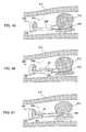
- FIG. 10is a schematic sectional view illustrating the body tissue to be cut and adjacent body tissues thereof, showing a state in which the insertion tube of the endoscope is disposed in front of the body tissue to be cut.
- FIG. 11is a schematic sectional view illustrating the body tissue to be cut and the adjacent body tissues thereof, showing a state in which a catheter is projected from a channel of an insertion tube of an endoscope, and a hooked cutting electrode is projected from the catheter and hooked onto the body tissue to be cut.
- FIG. 12is a schematic sectional view illustrating the body tissue to be cut in the body and the adjacent body tissues, showing a state in which the cutting electrode hooked onto the body tissue to be cut is pulled and a traction force is applied to the body tissue.
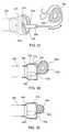
- FIG. 13is a plan view illustrating the whole constitution of the treatment device for endoscope of an embodiment of the present invention.
- FIG. 14is a plan view illustrating the constitution of a handle portion of the treatment device for endoscope of an embodiment of the present invention.
- FIG. 15is a perspective view illustrating a stopper of a control wire mounted on the handle portion of the treatment device for endoscope of the present invention.
- FIG. 16is a sectional view of the handle portion taken along the line of A to A in FIG. 15 , showing a state in which a stop nut for regulating the movable range of a stopper of the control wire is used to regulate the movement of the stopper and that in which it is used to release the regulation of the stopper.
- FIG. 17shows a state in which a preformed spring electrode mounted on the treatment device for endoscope of the present invention is projected from the distal end of the catheter and fully extended.
- FIG. 18shows a state in which the preformed spring electrode mounted on the treatment device for endoscope of the present invention is fully retracted into the catheter.
- FIG. 19shows a state in which the preformed spring electrode of the treatment device for endoscope of the present invention is partially projected from the catheter and other portions of the spring electrode are retracted into the catheter.
- FIG. 20is a view illustrating a modification of the preformed spring electrode mounted on the treatment device for endoscope of the present invention, in which an insulator is mounted at the leading end of the cutting electrode.
- FIG. 21is a view showing a state in which the treatment device for endoscope shown in FIG. 11 is used to hook the body tissue to be cut by the preformed spring electrode.
- FIG. 22is a view illustrating another modification of the preformed spring electrode of the treatment device for endoscope of the present invention, in which changed is a configuration of the insulator mounted at the leading end of the cutting electrode.
- FIG. 23is a view illustrating a modification of the treatment device for endoscope of the present invention, showing a state in which the body tissue to be cut is hooked by the preformed spring electrode.
- FIG. 24shows a state in which the leading end of the preformed spring electrode hooking the body tissue to be cut is grasped by using grasping forceps passed through a channel different from that of the electrode in the treatment device for endoscope shown in FIG. 23 .
- FIG. 25is a view illustrating a modification of the treatment device for endoscope of the present invention, showing a state in which the body tissue to be cut is hooked by the preformed spring electrode.
- FIG. 26is a view illustrating a modification of the treatment device for endoscope of the present invention, or a plan view illustrating a treatment device provided with a handle for operating the preformed spring electrode and a handle for operating the grasping forceps.
- FIG. 27is a view illustrating a modification of the treatment device for endoscope of the present invention, showing a state in which the leading end of the preformed spring electrode hooking the body tissue to be cut is restrained by using a loop of a snare passed through a channel different from that of the electrode.
- FIG. 28is a view illustrating a modification of the treatment device for endoscope of the present invention, showing a state in which the leading end of the preformed spring electrode hooking the body tissue to be cut is restrained by using a loop of a snare projected from a through hole formed on the side wall of the catheter.
- FIG. 29is a view illustrating a modification of the treatment device for endoscope of the present invention, showing a state in which the body tissue to be cut is hooked by the preformed spring electrode.
- FIG. 30shows a state in which the leading end of the preformed spring electrode hooking the body tissue to be cut is restrained by using a traction instrument passed through a channel the same as that of the electrode in the treatment device for endoscope shown in FIG. 29 .
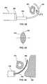
- FIG. 31is a view illustrating a modification of the treatment device for endoscope of the present invention, showing a state in which the leading end of the preformed spring electrode projected from the through hole formed on the side wall of the catheter and having hooked the body tissue to be cut is restrained by using the grasping forceps projected from the distal end of the catheter.
- FIG. 32is a view illustrating a modification of the treatment device for endoscope of the present invention, showing a state in which the body tissue to be cut is hooked by the preformed spring electrode projected from the distal end of a double-structured catheter.
- FIG. 33shows a grasping structure of the preformed spring electrode mounted on the side wall of the catheter in the treatment device for endoscope shown in FIG. 32 .
- FIG. 34shows a state in which the leading end of the preformed spring electrode hooking the body tissue to be cut is grasped by using the grasping structure formed on the side wall of the catheter in the treatment device for endoscope shown in FIG. 32 .
- FIG. 35is a view illustrating a modification of the treatment device for endoscope of the present invention, showing a treatment device capable of changing the configuration of the preformed spring electrode in a three-dimensional manner.
- FIG. 36shows a state in which the preformed spring electrode is changed in configuration to hook the body tissue to be cut in the treatment device for endoscope shown in FIG. 35 .
- FIG. 37is a view illustrating a modification of the treatment device for endoscope of the present invention, showing a treatment device which has at the distal end of the catheter a cap capable of holding the body tissue to be cut between the cap and the preformed spring electrode.
- FIG. 38shows a state in which the body tissue to be cut is held between the cap and the preformed spring electrode in the treatment device for endoscope shown in FIG. 37 .
- FIG. 39is a modification of the treatment device for endoscope shown in FIG. 37 , showing a treatment device from which a hook portion at the leading end of the electrode is deleted due to an increased rigidity of the preformed spring electrode.
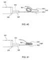
- FIG. 40is a view illustrating a modification of the treatment device for endoscope of the present invention, showing a treatment device provided with the preformed spring electrode bent approximately in a V-letter shape.
- FIG. 41shows a state in which the body tissue to be cut is held by the preformed spring electrode of the treatment device for endoscope shown in FIG. 40 .
- FIG. 42is a view illustrating a modification of the treatment device for endoscope of the present invention, showing a treatment device having the preformed spring electrode, the cross section of which is an oval.
- FIG. 43is a sectional view illustrating the preformed spring electrode taken along the line B to B in FIG. 42 .
- FIG. 44is a view illustrating a modification of the treatment device for endoscope of the present invention, showing a treatment device in which the preformed spring electrode is partially covered by an insulator.
- FIG. 45is a view explaining a technique for removing a polyp growth on the large intestine by using the treatment device for endoscope shown in FIG. 23 , showing a state in which an insertion tube of the endoscope is inserted into the large intestine and the polyp is hooked by using the preformed spring electrode which has been hooked.
- FIG. 46shows a state in which the insertion tube of the endoscope is inserted into the large intestine and the leading end of the preformed spring electrode hooking the polyp is grasped by the grasping forceps.
- FIG. 47shows a state in which an electric current is supplied to the electrode to remove the polyp, while traction is applied to the polyp by using the preformed spring electrode and the grasping forceps.
- RFradio frequency
- a variety of prior art devicesare available for RF treatment. Some of these devices are specifically linked to the type of endoscope being used; for example, the cutting loops designed specifically for transurethral resection with a urological resecto scope. Others are designed to perform a specific type of procedure through generic endoscopes; for example, papillotomy knive (sphincterotomy knife) designed specifically to incise the Papilla of Vater, and snares designed specifically to remove colon polyps—all performed through standard flexible endoscopes. Other cutting devices are designed for more generic applications; such as needle-tipped electrodes which can be used for a variety of endoscopic cutting applications.
- the ability to apply traction to body tissueis a key element in cutting body tissue easily and precisely.
- the body tissue being excisedis usually grasped with a treatment device and stretched to place it under slight tension in order to stabilize the body tissue, to guide the incision, and to separate the incised parts.
- the body tissueis held with a grasping instrument(s), while a scalpel or electrosurgical cutting device is used to incise the body tissue.
- papillotomy kniveIn applications of flexible endoscopy, the ability to put traction on the body tissue being cut is often difficult or impossible with devices currently available.
- Some devicessuch as papillotomy knive, are designed so that the device itself puts pressure on the body tissue as the cut is being made.
- the operatorcloses the handle on the device to bow the tip of the papillotomy knive, forcing the cutting wire into the stretched sphincter muscle.
- the degree of tension placed on the body tissue by the cutting electrodeis controlled by the degree to which the operator closes the handle of the papillotomy knive.
- the cutting electrodee.g., cutting wire
- the leading end of the endoscopeis accomplished by movements of the shaft of the endoscope, and/or manipulation of the angle control knobs of the endoscope. Both of these maneuvers are often awkward and imprecise compared to using handheld cutting tools.
- the movement of the cutting toolis often achieved by moving the endoscope itself—an often difficult and cumbersome procedure.
- the easiest maneuver to make with an electrode which passes through the channel of a flexible endoscopeis to pull back on the shaft of the device, thereby withdrawing it into the channel of the endoscope.
- Movement of the electrode towards the endoscope leading end by withdrawing the electrode shaft into the endoscope's channelhas several advantages over moving the endoscope itself: 1) the electrode moves in a predefined, easily predicted direction—directly towards the leading end of the endoscope, 2) the electrode can place considerable force on the body tissue, usually greater force than can be asserted by moving the leading end of the endoscope itself, and 3) if the electrode is placed behind the body tissue being cut, withdrawal of the electrode will put traction on the body tissue being cut, while at the same time maintaining a clear view of the site of the incision.
- FIG. 1 through to FIG. 6schematically illustrate the distal end of several prior art wire-type cutting electrodes which are in common use for endoscopic surgery.
- FIG. 1illustrates a needle electrode having a projected cutting wire 102 and
- FIG. 2illustrates a snare having a loop cutting wire 112 .
- FIG. 3illustrates papillotomy knive having a cutting wire 104 .
- the papillotomy knive shown in FIG. 3bends the distal end of the catheter 100 upon application of tensile force and closely attach to the catheter 100 upon release of the tensile force.
- FIG. 4 through FIG. 6illustrate an electrode having a cutting wire 106 .
- the distal end 108 of the cutting wire 106 shown in FIG. 4is insulated.
- a triangular-shaped metal chip 110is provided at the leading end of the cutting wire 106 shown in FIG. 5 .
- a small fixed-type hook-shaped wire chip 114is provided at the leading end of the cutting wire 106 shown in FIG. 6 .
- the electrode wirecan be closely attached to the catheter 100 or retracted into the catheter 10 so as to be passed through the endoscope's channel.
- FIG. 1 through FIG. 6illustrate a state in which the distal end of the electrode wire is exposed from the catheter 100 and a state in which the distal end of the electrode wire is retracted into the catheter 100 so as to be passed through the endoscope's channel.
- snares in FIG. 2are designed to be looped over a protruding piece of body tissue, most typically a polyp, and the body tissue is cut off by closing the snare's handle, thereby pulling the cutting wire through the body tissue as RF current is applied.
- papillotomy knive in FIG. 3are specifically designed to be inserted into a papillary orifice such as the ductal opening of the Papilla of Vater. The handle of the papillotomy knife is then “closed” to put tension on the cutting wire 104 and to bow the leading end of the catheter 100 . This presses the cutting wire 104 against the body tissue as RF current is applied and the incision is made.
- manipulating the handle of the device during the therapeutic procedureis not necessary.
- the handleis used only to place the electrode in its exposed, ready for use, position.
- the endoscopeitself must then be manipulated to press the cutting electrode against the body tissue and to control the direction of movement of the electrode through the body tissue.
- manipulating the cutting electrode by manipulating the endoscopeis often awkward and provides poor control over the direction of the electrode, or the cutting direction.
- FIG. 7schematically illustrates the use of a flexible endoscope to incise the fallopian tube of a female patient with a needle electrode.
- the insertion tube 200 of the flexible endoscope 212has been inserted into the patient's mouth (not illustrated), through the patient's esophagus into the patient's stomach 204 .
- An incision 206 in the wall of the stomachallows the endoscope insertion tube 200 to pass from the interior of the stomach into the peritoneal cavity and to approach the pelvic organs of the patient.
- the patient's uterus 218 and fallopian tubes 208are shown.
- a cutting wire 102is protruded from the distal end of a catheter 100 passed through the endoscope's channel (inner lumen) and is pressed against the fallopian tube in order to incise it.
- a handle 216 attached to the proximal end of the catheter 100allows the operator to retract and extend the cutting wire 102 into and out of the proximal end of the catheter 100 .
- the handle 216is also connected to an active cord 220 which supplies RF current from an RF generator (not illustrated) to the electrode wire.
- the handle 216is used to protrude and retract the cutting wire 102 from the distal end of the catheter 100 , it has no role in positioning the cutting wire 102 along the body tissue and moving the cutting wire 102 in the intended cutting direction.
- the operatoraccomplishes these tasks by manipulating the insertion tube 200 of the endoscope and by operating the angle control knobs 214 which control the movement of the distal end of the endoscope.
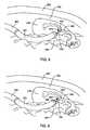
- FIG. 8illustrates an enlarged view of the treatment applied to the fallopian tube.
- the operatoris intending to cut through the fallopian tube to severe it, one step of many in a procedure to render the patient infertile.
- FIG. 8illustrates the distal end of the endoscope's insertion tube 200 and a bending section 222 lying in the intraperitoneal cavity 302 of the lower abdomen of the patient.
- the cutting wire 102 and the catheter 100protrude from the distal end of the insertion tube and are positioned near the patient's right fallopian tube 208 .
- the cutting wiremust be pressed against the flaccid body tissue of the fallopian tube 208 as the RF current is applied to the cutting wire 102 .
- the only means of controlling the direction in which the cutting wire 102 movesis through manipulation of the endoscope's insertion tube 200 by grasping that portion which exits from the patient's mouth, or by manipulating the angle control knobs on the endoscope. Operating the angle control knobs will change the deflection of the bending section 222 of the endoscope by remote control. Both of these maneuvers are awkward and imprecise. Furthermore, as illustrated in FIG. 8 , in many situations, pressing the cutting wire 102 against the body tissue in the direction 224 shown in FIG. 8 , will force the fallopian tube 208 against the underlying pelvic organs and the cutting wire 102 will likely cut and damage this body tissue as well.
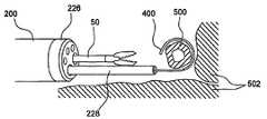
- FIG. 9illustrates an embodiment of the endoscope-use device of the present invention.
- the needle electrodeis replaced by the preformed spring electrode 400 .
- the electrode 400which protrudes from the distal end of the catheter 228 is hooked and has been placed around the distal side of the fallopian tube 208 .
- the deviceelevates the fallopian tube 208 off of the pelvic organs 304 rather than pressing it into these organs.
- RF currentis applied to the electrode 400 from an electrosurgical current generator connected to the proximal handle of the device (not shown).
- the operatorpulls the catheter 228 so as to remove the electrode 400 in the direction 402 shown in FIG. 9 .
- This actionputs traction on the body tissue facilitating the cut.
- This actionis also easily performed by simply pulling the proximal portion of the catheter which extends from the control section of the endoscope. No specific manipulations of the endoscope insertion tube 200 or bending section 222 are required.
- FIG. 10 through FIG. 12illustrate how the device of the present invention can be used to isolate the body tissue intended to be cut from other surrounding body tissues.
- the distal end 226 of the endoscope insertion tube 200is first positioned so that the catheter 228 is placed between the body tissue 500 to be cut and other adjacent body tissues 502 that must be preserved.
- the preformed spring electrode 400is then protruded from the distal end of the flexible catheter 228 by manipulating the handle of the device (not shown) to allow the electrode 400 to hook the body tissue 500 to be cut.
- the device of the present inventionis manufactured from specific materials and by a manufacturing method used for assembling electrode elements, forms a specific hooked shape when the electrode protrudes from the distal end of the flexible catheter 228 .
- the endoscopeis then manipulated to move the body tissue to be cut away from the other adjacent body tissues 502 in order not to accidentally burn or cut them through contact with the electrified electrode 400 .
- the operatorthen withdraws the flexible catheter 228 into the channel of the endoscope, pulls the body tissue 500 to be cut to separate it from all adjacent body tissues structures.
- the body tissuecan be incised by applying RF electrosurgical current while pulling the flexible catheter 228 and moving the electrode 400 together with the distal end of the endoscope in the direction 506 .
- the entire procedureis performed under visual control by keeping all manipulations in the field of view 504 of the endoscope.
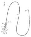
- FIG. 13illustrates an overall view of an treatment device for endoscope of the present invention.
- the preformed spring electrode 400protrudes from the distal end of a flexible catheter 228 .
- the flexible catheteris long enough to pass completely through the channel (inner lumen) of a flexible endoscope, and has some additional length to make it convenient to use.
- the proximal end of the catheter 228is connected to a handle 606 .
- a slider 600 on the handle 606is connected to the proximal end of a control wire 602 .
- the control wire 602runs through the internal lumen of the flexible catheter 228 and is attached at its distal end with the preformed spring electrode 400 .
- control wire 602moves the control wire 602 back and forth, which in turn protrudes the electrode 400 from the distal end of the flexible catheter 228 , or alternatively withdraws the spring electrode completely into the flexible catheter 228 .
- the proximal end of the control wire 602is connected to an RF electrical connector 604 mounted on the slider 600 .
- An electrical cord(not shown) can be connected to this connector 604 to bring RF electrosurgical current from a standard electrosurgical generator (also not shown) to the device. The RF current then travels through the RF connector 604 and the control wire 602 to the electrode 400 connected to the leading end of the control wire 602 .
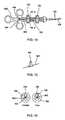
- the handle 606 of this embodimenthas a stopper 700 fixed to the control wire 602 and stop nuts 702 and 704 which limit the movement range of the stopper 700 which moves together with the control wire 602 .
- FIG. 7 through FIG. 16show a further detailed construction of the handle 606 of the embodiment shown in FIG. 13 .
- a slider 600 on the handle 606is attached to the proximal end of the control wire 602 which runs through the lumen of the flexible catheter 228 . Movement of the slider 600 protrudes or retracts the preformed spring electrode 400 (not shown) on the distal end of the flexible catheter 228 .
- a stopper 700is affixed to the control wire 602 as illustrated in FIG. 14 . This stopper 700 limits movement of the control wire 602 .
- a proximally-positioned stop nut 702limits movement of the control wire 602 as the slider 600 on the handle 606 is “closed,” thereby limiting the degree that the electrode can be withdrawn into the distal end of the flexible catheter 228 .
- a distally-positioned stop nut 704conversely limits the degree that the handle can be “opened,” thereby limiting the length of the electrode that protrudes from the distal end of the flexible catheter 228 . As a result, the size of the hook shape formed by the spring electrode is limited.
- each stop nut 702 and 704has a cutout 706 which allows the stopper 700 to bypass the stop nut 702 and 704 when the stop nut is rotated into the free position, as illustrated in FIG. 16 .
- This featureallows the operator to quickly put the handle 606 into a configuration in which the maximum and minimum limits of the control wire 602 movement are overridden.
- the slider 600can move back and forth freely without the stopper 700 encountering the stop nuts 702 and 704 .
- FIG. 14illustrates another embodiment of the treatment device for endoscope of the present invention.
- FIG. 17illustrates that the preformed spring electrode 400 is constructed of a material such as Nitinol or a suitable spring metal such that when it is unconstrained it curls into a hook shape. This hook shape is essential for the electrode 400 's ability to get behind body tissue and to incise them as the electrode is pulled towards the distal end of the endoscope.
- the material of the spring electrode 400must also conduct RF current, in addition to having the ability to return to a predetermined shape.
- the spring electrode 400is attached to the distal end of the control wire 602 which controls its movement in and out of the flexible catheter 228 .
- the flexible catheter 228is constructed of polymer tubing such as polytetrafluoroethylene (e.g., Teflon), but other materials are equally suitable.
- polymer tubingsuch as polytetrafluoroethylene (e.g., Teflon), but other materials are equally suitable.
- Teflonpolytetrafluoroethylene
- a thin-walled metal sheath 800is inserted into the distal end of the catheter 228 .
- FIG. 18illustrates, when the preformed spring electrode 400 is completely retracted into the flexible catheter 228 , it is totally constrained and lies within the lumen of the flexible catheter 228 . In this configuration the device can be safely advanced into or retracted from the channel (inner lumen) of a flexible endoscope.
- FIG. 19illustrates, it is possible to use the device in an intermediate position wherein the preformed spring electrode 400 protrudes only partially out of the distal end of the flexible catheter 228 .
- the stop nuts 702 and 704 on the handle 606 illustrated in FIG. 4are used to adjust the relative length of the spring electrode 400 which protrudes from the flexible catheter 228 as the handle 606 is operated between its maximum and minimum settings.
- FIG. 20illustrates an alternative embodiment of the preformed spring electrode 400 .
- the distal end of the spring electrode 400is covered by insulating material such as a ceramic bead, a polymer bead, or other material which cannot conduct RF current.
- FIG. 21illustrates, according to the embodiment, if the body tissue 500 being cut by the preformed spring electrode 400 is close to the other body tissue, the insulator chip 150 of the electrode 400 prevents these adjacent body tissues 502 from contacting the energized metal portion of the cutting electrode 400 .
- FIG. 22shows a modification of the embodiment shown in FIG. 21 , illustrating that the size and shape of the insulator chip 150 of the device may have a shape designed specifically to help capture and hold the body tissue which the device is intended to cut.
- FIG. 7 and FIG. 9illustrate that the method and apparatus of the present invention has application in endoscopic transgastric surgery (by way of example—the procedure of female sterilization), the present invention has many other broad applications. It can be used in rigid endoscopic (e.g., laparoscopic) surgery as well as all forms of flexible endoscopic surgery.
- the deviceis well suited for incising large structures such as the fallopian tubes herein illustrated. However, the device can also be made proportionally smaller with a smaller hook and/or catheter. Smaller embodiments of the present invention will be useful for incising exposed blood vessels, ducts, nerves, connective body tissue, muscle fibers, omentum, etc.
- the treatment device for endoscope of the present invention shown in FIG. 23 and FIG. 24is constituted with the treatment device for endoscope shown in FIG. 13 and a grasping forceps 50 as a restraint instrument.
- the distal end 226 of the insertion tube 200 of the endoscopeis disposed between the body tissue 500 to be cut and other adjacent body tissues to be preserved 502 , and a flexible catheter 228 is projected through the channel of an insertion tube 200 from the distal end 226 thereof. Then, as illustrated in FIG.
- the electrode 400recovers a bent configuration which has been imparted in advance, thereby the electrode 400 is hooked onto the body tissue 500 to be cut. Then, the grasping forceps 50 is projected through another channel of the insertion tube 200 from the distal end 226 , and the leading end of the electrode 400 is grasped by the grasping forceps 50 . Then, the flexible catheter 228 including the electrode 400 and the grasping forceps 50 is pulled into the channel of the insertion tube 200 in synchronization and the body tissue 500 to be cut is pulled and drawn away from the adjacent body tissues 502 .
- the electrode 400 hooking the body tissue 500is moved to the distal end 226 of the insertion tube 200 , and RF current is applied to the electrode 400 , thereby the body tissue 500 is incised.
- the grasping forceps 50is operated to release the leading end of the electrode 400 , thereby forcibly pulling the electrode 400 into the catheter 228 .
- the electrode 400is retracted into the catheter 228 , while being linearly extended to resemble the configuration of the catheter 228 .
- the grasping forceps 50is used to grasp the leading end of electrode 400 , thereby preventing the electrode 400 from undergoing an unintended deformation due to a reaction force acting on the electrode 400 from the body tissue 500 to be cut. Then, the electrode 400 is joined to the grasping forceps 50 to secure the body tissue 500 to be cut thereinside, thereby the electrode 400 can incise the body tissue 500 to be cut without fail. Further, all operations can be performed while the treatment is observed from start to finish under a visual field 504 of the endoscope.
- the treatment device for endoscope of the present invention shown in FIG. 25 and FIG. 26is constituted with a flexible catheter 230 , a control wire 602 passed through the flexible catheter 230 , a preformed spring electrode 400 connected to the distal end of a control wire 602 , a handle 606 mounted on the proximal end of the flexible catheter 230 , the grasping forceps 50 passed through the flexible catheter 230 , and a handle 240 of the grasping forceps 50 mounted on the proximal end of the flexible catheter 230 .
- the flexible catheter 230is provided with a lumen 232 a through which a control wire 602 of the electrode 400 is passed and another lumen 232 b through which the grasping forceps 50 is passed.
- the proximal end of the flexible catheter 230is branched into two directions.
- a handle 606 for operating the electrode 400is mounted at one proximal end, and a handle 240 for operating the grasping forceps 50 is mounted at the other proximal end.
- the handle 240is provided with a slider 244 for pushing and pulling a control wire 242 to open or close a pawl at the leading end of the grasping forceps 50 .
- the control wire 24is moved back and forth, thereby the claw at the leading end of the grasping forceps 50 is opened or closed.
- the distal end 226 of the insertion tube 200 of the endoscopeis disposed between the body tissue 500 to be cut and other adjacent body tissues, and a flexible catheter 230 is projected through the channel of the insertion tube 200 from the distal end 226 .
- a handle 606 of the treatment deviceis operated to project an electrode 400 from the distal end of the flexible catheter 230 , the electrode 400 recovers a bent configuration which has been imparted in advance, thereby the electrode 400 is hooked onto the body tissue 500 to be cut.
- a handle 240is operated to project the grasping forceps 50 from the distal end 226 of the flexible catheter 230 , and the leading end of the electrode 400 is grasped by the grasping forceps 50 .
- the flexible catheter 230 including the electrode 400 and the grasping forceps 50are pulled into the channel of the insertion tube 200 and the body tissue 500 to be cut is pulled and drawn away from adjacent body tissues.
- the electrode 400 hooking the body tissue 500is moved to the distal end 226 of the insertion tube 200 , and RF current is applied to the electrode 400 , thereby the body tissue 500 is incised.
- the grasping forceps 50is operated to release the leading end of the electrode 400 , thereby forcibly pulling the electrode 400 into the catheter 230 .
- the electrode 400is retracted into the catheter 230 while being linearly extended to resemble the configuration of the catheter 230 .
- the grasping forceps 50is used to grasp the leading end of the electrode 400 , thereby making it possible to incise the body tissue 500 to be cut by using the electrode 400 without fail. Further, all operations can be performed while the treatment is observed from start to finish under the visual field 504 of the endoscope.
- the treatment device for endoscope of the present invention shown in FIG. 27is provided with a snare 250 as a restraint instrument in place of the grasping forceps 50 . Further, the leading end of the preformed spring electrode 400 is provided with a hook portion 402 for hooking the loop 252 of the snare 250 .
- the distal end 226 of the insertion tube 200 of the endoscopeis disposed between the body tissue 500 to be cut and other adjacent body tissues, and a flexible catheter 228 is projected through the channel of the insertion tube 200 from the distal end 226 .
- a handle 606 of the treatment deviceis operated to project an electrode 400 from the distal end of the flexible catheter 228 , the electrode 400 recovers a bent configuration which has been imparted in advance, thereby the electrode 400 is hooked onto the body tissue 500 to be cut.
- the snare 250is projected through another channel of the insertion tube 200 from the distal end 226 and the snare 250 is operated to hook the loop 252 onto the hook portion 402 of the electrode 400 .
- the flexible catheter 228 including the electrode 400 and the snare 250are pulled into the channel of the insertion tube 200 in synchronization, and the body tissue 500 to be cut is pulled and drawn away from the adjacent body tissues.
- the electrode 400 hooking the body tissue 500is moved to the distal end 226 of the insertion tube 200 , and RF current is applied to the electrode 400 , thereby the body tissue 500 is incised.
- the snare 250is operated to release the leading end of the electrode 400 , thereby forcibly pulling the electrode 400 into the catheter 228 .
- the electrode 400is retracted into the catheter 228 while being linearly extended to resemble the configuration of the catheter 228 .
- the snare 250is used to grasp the leading end of the electrode 400 , thereby making it possible to incise the body tissue 500 to be cut by using the electrode 400 without fail. Further, all operations can be performed while the treatment is observed from start to finish under a visual field 504 of the endoscope.
- treatmentis performed by using the endoscope having two channels of an insertion tube 200 .
- FIG. 28it is possible to perform treatment by using an endoscope having only one channel of an insertion tube 200 .
- a through hole 228 ais formed on the side wall at the distal end of the catheter 228 , and a loop 252 which constitutes a snare is passed through the through hole 228 a.
- the distal end 226 of the insertion tube 200 of the endoscopeis disposed between the body tissue 500 to be cut and other adjacent body tissues, and a flexible catheter 228 is projected through the channel of the insertion tube 200 from the distal end 226 .
- a handle 606 of the treatment deviceis operated to project a preformed spring electrode 400 from the distal end of the flexible catheter 228 , the electrode 400 recovers a bent configuration which has been imparted in advance, thereby the electrode 400 is hooked onto the body tissue 500 to be cut.
- a loop 252is operated and hooked onto a hook portion 402 of the electrode 400 .
- the flexible catheter 228 including the electrode 400 and the loop 252is pulled into the channel of the insertion tube 200 , and the body tissue 500 to be cut is pulled and drawn away from the adjacent body tissues. Then, the electrode 400 hooking the body tissue 500 is moved to the distal end 226 of the insertion tube 200 , and RF current is applied to the electrode 400 , thereby the body tissue 500 is incised.
- the loop 252 constituting a snareis passed through a through hole 228 a formed on the side wall at the distal end of the catheter 228 , thereby the loop 252 separates from the distal end of the catheter 228 . Therefore, the loop 252 can easily catch the hook portion 402 at the leading end of the electrode 400 .
- the treatment device for endoscope of the present invention shown in FIG. 29 and FIG. 30is provided with a preformed spring electrode 410 as a cutting electrode and a traction instrument 260 as a restraint instrument.
- the leading end of the traction instrument 260is projected from the distal end of a flexible catheter 230 .
- a loop 412is provided at the leading end of the preformed spring electrode 410 .
- a ball portion 262 for hooking the loop 412 of the electrode 410is provided at the leading end of the traction instrument 260 .
- a control wire 602 of the electrode 400is passed through a lumen 232 a of the flexible catheter 230 , and the traction instrument 260 is passed through another lumen 232 b .
- the proximal end of the flexible catheter 230is branched into two directions.
- a handle for operating the electrode 410is mounted at one proximal end, and a handle for operating the traction instrument 260 is mounted at the other proximal end. When the handle for the traction instrument 260 is operated, the ball portion 262 mounted at the leading end of the traction instrument 260 is moved back and forth.
- the distal end 226 of the insertion tube 200 of the endoscopeis disposed between the body tissue 500 to be cut and other adjacent body tissues, and a flexible catheter 230 is projected through the channel of the insertion tube 200 from the distal end 226 .
- a handle of the treatment deviceis operated to project an electrode 410 from the distal end of the flexible catheter 230
- the electrode 410recovers a bent configuration which has been imparted in advance, thereby the electrode 410 is hooked onto the body tissue 500 to be cut.
- a traction instrument 260is operated to hook a ball portion 262 onto a loop 412 of the electrode 410 .
- the flexible catheter 230 including the electrode 410 and the traction instrument 260is pulled into the channel of the insertion tube 200 ; and the body tissue 500 to be cut is pulled and drawn away from the adjacent body tissues.
- the electrode 410 hooking the body tissue 500is moved to the distal end 226 of the insertion tube 200 , and RF current is applied to the electrode 410 , thereby the body tissue 500 is incised.
- the traction instrument 260is operated to release the loop 412 of the electrode 410 , thereby forcibly pulling the electrode 410 into the catheter 230 .
- the electrode 410is retracted into the catheter 230 while being linearly extended to resemble the configuration of the catheter 230 .
- the traction instrument 260is used to grasp the leading end of the electrode 410 , thereby it is possible to incise the body tissue 500 to be cut by using the electrode 410 without fail. Further, all operations can be performed while the treatment is observed from start to finish under a visual field 504 of the endoscope.
- the preformed spring electrode 400 as a cutting electrodeis projected from a through hole 228 a formed on the side wall at the distal end of the catheter 228 , and the grasping forceps 50 is projected from an opening at the distal end of the catheter 228 .
- the proximal end of the flexible catheter 228is branched into two directions.
- a handle for operating the electrode 400is mounted at one proximal end of the flexible catheter 228
- a handle for operating the grasping forceps 50is mounted at the other proximal end of the flexible catheter 228 .
- the distal end 226 of the insertion tube 200 of the endoscopeis disposed between the body tissue 500 to be cut and other adjacent body tissues, and the flexible catheter 228 is projected through the channel of the insertion tube 200 from the distal end 226 .
- the electrode 400recovers a bent configuration which has been imparted in advance, thereby the electrode 400 is hooked onto the body tissue 500 to be cut.
- a handleis operated to project grasping forceps 50 from the distal end of the flexible catheter 228 , and the leading end of the electrode 400 is grasped by the grasping forceps 50 .
- the flexible catheter 228 including the electrode 400 and the grasping forceps 50are pulled into the channel of the insertion tube 200 and the body tissue 500 to be cut is pulled and drawn away from adjacent body tissues.
- the electrode 400 hooking the body tissue 500is moved to the distal end 226 of the insertion tube 200 , and RF current is applied to the electrode 400 , thereby the body tissue 500 is incised.
- the grasping forceps 50is operated to release the leading end of the electrode 400 , thereby forcibly pulling the electrode 400 into the catheter 228 .
- the electrode 400is retracted into the catheter 228 while being linearly extended to resemble the configuration of the catheter 228 .
- the grasping forceps 50is used to grasp the leading end of the electrode 400 , thereby it is possible to incise the body tissue 500 to be cut by using the electrode 400 without fail. Further, all operations can be performed while the treatment is observed from start to finish under a visual field 504 of the endoscope. Further, the grasping forceps 50 is passed through the through hole 228 a formed on the side wall at the distal end of the catheter 228 , thereby the grasping forceps 50 separates from the distal end of the catheter 228 . Therefore, the grasping forceps 50 can easily catch the leading end of the electrode 400 .
- the catheter 234acts as a restraint instrument.
- the catheter 234is provided with a double structure made up of an inner sheath 236 and an outer sheath 238 , and a control wire 602 of the electrode 400 is passed through the inner sheath 236 .
- the inner sheath 236is slidable back and forth with respect to the outer sheath 238 .
- a disk 246which is approximately as large as the outer diameter of the outer sheath 238 is fixed at the distal end of the inner sheath 236 in such a way that an opening at the distal end of the inner sheath 236 is exposed at the center.
- the disk 246is brought into contact with the distal end face of the outer sheath 238 .
- the proximal end of the flexible catheter 234is branched into two directions.
- a handle for operating the electrode 400is mounted at one proximal end of the flexible catheter 234
- a handle for operating the inner sheath 236is mounted at the other proximal end of the flexible catheter 234 .
- the distal end 226 of the insertion tube 200 of the endoscopeis disposed between the body tissue 500 to be cut and other adjacent body tissues, and the flexible catheter 234 is projected through the channel of the insertion tube 200 from the distal end 226 .
- the electrode 400recovers a bent configuration which has been imparted in advance, thereby the electrode 400 is hooked onto the body tissue 500 to be cut.
- FIG. 32when a handle of the treatment device is operated to project an electrode 400 from the distal end of the catheter 234 , the electrode 400 recovers a bent configuration which has been imparted in advance, thereby the electrode 400 is hooked onto the body tissue 500 to be cut.
- the handleis operated to move the inner sheath 236 forward with respect to the outer sheath 238 , thereby the disk 246 separates from the distal end face of the outer sheath 238 .
- the electrode 400is inserted into a space between the disk 246 and the distal end face of the outer sheath 238 , and the inner sheath 236 is this time moved backward with respect to the outer sheath 238 , thereby interposing the leading end of the electrode 400 between the disk 246 and the distal end face of the outer sheath 238 .
- the flexible catheter 234 including the electrode 400is pulled into the channel of the insertion tube 200 , and the body tissue 500 to be cut is pulled and drawn away from adjacent body tissues. Then, the electrode 400 hooking the body tissue 500 is moved to the distal end 226 of the insertion tube 200 , and RF current is applied to the electrode 400 , thereby the body tissue 500 is incised. After incision of the body tissue 500 , the catheter 234 is operated to release the leading end of the electrode 400 , thereby forcibly pulling the electrode 400 into the catheter 234 . As a result, the electrode 400 is retracted into the catheter 234 while being linearly extended to resemble the configuration of the catheter 234 .
- the catheter 234is used to grasp the leading end of the electrode 400 , thereby it is possible to incise the body tissue 500 to be cut by using the electrode 400 without fail. Further, all operations can be performed while the treatment is observed from start to finish under the visual field 504 of the endoscope.
- the preformed spring electrode 400can freely obtain a three-dimensional configuration.
- a control wire 602 of the electrode 400is passed through a flexible sheath 270 , and the flexible sheath 270 through which the control line 602 is passed is inserted into the catheter 228 .
- the flexible sheath 270can be freely rotated with respect to the catheter 228 in a circumferential direction.
- the control wire 602can also be freely rotated with respect to the flexible sheath 270 in a circumferential direction.
- the flexible sheath 270is made of an insulating material and imparted at the distal end thereof in advance with a bent configuration so as to give an arc.
- the electrode 400is also imparted at the leading end thereof in advance with a bent configuration so as to give an arc.
- the control wire 602 of the electrode 400is rotated with respect to the flexible sheath 270 in a circumferential direction, thereby a three-dimensional bent configuration to the electrode 400 is imparted.
- the distal end 226 of the insertion tube 200 of the endoscopeis disposed between the body tissue 500 to be cut and other adjacent body tissues, and the catheter 228 is projected through the channel of the insertion tube 200 from the distal end 226 .
- the electrode 400recovers a bent configuration which has been imparted in advance.
- the flexible sheath 270when the flexible sheath 270 is pressed into the catheter 228 , with the control wire 602 restrained with respect to the flexible sheath 270 , and the flexible sheath 270 is projected from the distal end of the catheter 228 , the flexible sheath 270 also recovers a bent configuration which has been imparted in advance. Then, as illustrated in FIG. 36 , the control wire 602 is rotated with respect to the flexible sheath 270 in a circumferential direction, thereby the electrode 400 is displaced so as to turn toward the distal end of the flexible sheath 270 . Each of the distal end of the flexible sheath 270 and the electrode 400 is provided with an arc-like bent configurations in advance.
- the leading end of the treatment device including the electrode 400 and the distal end of the flexible sheath 270obtain a three-dimensional bent configuration. Further, the three-dimensional configuration changes according to an extent to which the electrode 400 is displaced with respect to the distal end of the flexible sheath 27 .
- the electrode 400is freely changed in configuration according to the configuration and dimension of the body tissue 500 to be cut, thereby it is possible to accurately secure only the body tissue 500 in separation from other adjacent body tissues.
- the electrode 400 and the flexible sheath 270are forcibly pulled into the catheter 228 . As a result, the electrode 400 and the flexible sheath 270 are retracted into the catheter 228 while being linearly extended to resemble the configuration of the catheter 228 .
- the treatment device for endoscope of the present invention shown in FIG. 37 and FIG. 38is provided with a cap 274 wrapped at the distal end of the catheter 228 .
- the cap 274is provided with a contact face 276 for holding the body tissue 500 to be cut between itself and a preformed spring electrode 400 .
- the contact face 276is formed at the distal end of the cap 274 wrapped at the distal end of the catheter 228 , that is, at a site further away from the distal end of the catheter 228 , so as to be approximately parallel with the distal end face of the catheter 228 .
- the contact face 276is provided with three slits in such a way that the visual field of the endoscope is not restricted or the radiation of illumination light is not prevented in a state that the cap 274 is wrapped at the distal end of the catheter 228 .
- the electrode 400is projected from a slit 278 at the center, which is the largest among these three slits.
- the cap 274is provided with a hook hole (cutting-electrode fixing portion) 279 for hooking a hook portion 402 mounted at the leading end of the electrode 400 .
- the distal end 226 of the insertion tube 200 of the endoscopeis disposed between the body tissue 500 to be cut and other adjacent body tissues, and the flexible catheter 228 is projected through the channel of the insertion tube 200 from the distal end 226 . Then, when a handle of the treatment device is operated to project the electrode 400 from the distal end of the flexible catheter 228 , as illustrated in FIG. 37 , the electrode 400 recovers a bent configuration that has been imparted in advance.
- the electrode 400is hooked onto the body tissue 500 to be cut and the electrode 400 is further projected from the distal end of the flexible catheter 228 , thereby the electrode 400 is bent to a greater extent, thereby the hook portion 402 of the electrode 400 is close to the catheter 228 .
- the catheter 228 including the electrode 400is pulled into the channel of the insertion tube 200 , and the body tissue 500 to be cut is pulled and drawn away from adjacent body tissues.
- the catheter 228is further pulled into the channel of the insertion tube 200 , thereby the body tissue 500 is held between the contact face 276 of the cap 274 and the electrode 400 .
- the hook portion 403 of the electrode 400is inserted into the slit 276 .
- the electrode 400deforms so as to be bent to a lesser extent, and the hook portion 402 is hooked onto a hook hole 279 from inside of the cap 274 . Thereby, the leading end of the electrode 400 is fixed to the cap 274 . Therefore, the electrode 400 forms a loop to secure the body tissue 500 to be cut thereinside, it is possible to incise the body tissue 500 to be cut by using the electrode 400 without fail.
- the electrode 400is forcibly pulled into the catheter 228 , thereby the hook portion 402 is removed from the hook hole 279 , and the electrode 400 can be retracted into the catheter 228 .
- the hook portion 402is provided at the leading end of the electrode 400 .
- the electrode 400is high in rigidity, there is no need for providing the hook portion 402 or providing the hook hole 279 at the cap 274 .
- the catheter 228 including the electrode 400is pulled into the channel of the insertion tube 200 , the body tissue 500 is held between the contact face 276 of the cap 274 and the electrode 400 , and the leading end of the electrode 400 is inserted into the slit 278 .
- a control wire 602is pulled into the catheter 228 , as illustrated in FIG. 39 , the electrode 400 deforms so as to be bent to a lesser extent and the leading end thereof is hooked onto the edge of the slit 278 .
- the leading end of the electrode 400is fixed to the cap 274 .
- the treatment device for endoscope of the present invention shown in FIG. 40 and FIG. 41is provided with a preformed spring electrode 420 which is bent approximately in a V-letter shape in advance.
- the electrode 420is composed of a proximal portion 422 forming one side of the V-letter shape and continuing to the control wire 602 , and a distal portion 424 forming the other side of the V-letter shape and continuing to the proximal portion 422 .
- the distal portion 424is bent in such a way as to be folded back with respect to the proximal portion 422 .
- a space between the proximal portion 422 and the distal portion 424is made narrower as it moves away from the distal end of the control wire 602 .
- the distal portion 424is not linear in configuration but bent so as to be rapidly brought closer to the proximal portion 422 as it moving away from the distal end of the control wire 602 .
- the electrode 420is inserted into the catheter 228 , in a state that it is folded so that the distal portion 424 is firmly attached to the proximal portion 422 .
- the distal end 226 of the insertion tube 200 of the endoscopeis disposed between the body tissue 500 to be cut and other adjacent body tissues, and the flexible catheter 228 is projected through the channel of the insertion tube 200 from the distal end 226 .
- the electrode 420recovers a bent configuration that has been imparted in advance, and the electrode 420 is then hooked onto the body tissue 500 to be cut.
- the catheter 228 including electrode 420is pulled into the channel of the insertion tube 200 , as illustrated in FIG.
- the body tissue 500is entered into a rapidly narrowed space between the proximal portion 422 and the distal portion 424 , and held by an elastic force acting between the proximal portion 422 and the distal portion 424 . Thereby, the body tissue 500 is compressed to result in an increased hemostatic effect. Further, since the electrode 420 is strongly pressed to the body tissue 500 , an electric current is supplied to the body tissue 500 at a greater density, thereby cutting performance of the electrode 420 is improved. After incision of the body tissue 500 , the electrode 420 is forcibly pulled into the catheter 228 . As a result, the electrode 420 is retracted into the catheter 228 while being linearly extended to resemble the configuration of the catheter 228 .
- the treatment device for endoscope of the present invention shown in FIG. 42 and FIG. 43is provided with a preformed spring electrode 430 having an oval cross section.
- the cross section of the electrode 430is an oval in which the length of the arc of the electrode 430 in the direction of a first axis 432 from inside to outside is longer than the length in the direction of a second axis 434 orthogonal to the first axis 432 .
- the cross section of the electrode 430is an oval having the first axis 432 as a long axis and the second axis 434 as a short axis.
- the electrode 430intends to be difficult to deform so as to eliminate the bent configuration. Therefore, even if the catheter 228 including the electrode 430 is pulled strongly, the electrode 430 is less likely to be removed from the body tissue 500 . Thereby, the electrode 430 can incise the body tissue 500 without fail.
- the electrode 430has an oval shaped in cross section.
- the cross sectionis not restricted to an oval shape but may be a rectangular shape, as long as the above conditions are met.
- an insulator 440is provided along the preformed spring electrode 400 .
- the insulator 440covers the inside of the arc of the electrode 400 , that is, a portion excluding that which is pressed to the body tissue 500 to be cut. Thereby, adjacent body tissues 502 around the body tissue 500 to be cut are not damaged to result in an increase in safety.
- an insertion tube 200 of the endoscopeis inserted into the large intestine 510 .
- the distal end 226 of the insertion tube 200 of the endoscopeis disposed in front of a polyp to be cut 512 , and a flexible catheter 228 is projected through the channel of the insertion tube 200 from the distal end 226 .
- a handle 606 of the treatment deviceis operated to project a preformed spring electrode 400 from the distal end of the flexible catheter 228 , the electrode 400 recovers a bent configuration that has been imparted in advance, thereby the electrode 400 is hooked onto the root of the polyp 512 .
- FIG. 45when a handle 606 of the treatment device is operated to project a preformed spring electrode 400 from the distal end of the flexible catheter 228 , the electrode 400 recovers a bent configuration that has been imparted in advance, thereby the electrode 400 is hooked onto the root of the polyp 512 .
- FIG. 45when a handle 606 of the treatment device is operated to project a pre
- grasping forceps 50is projected through another channel of the insertion tube 200 from the distal end 226 , thereby the grasping forceps 50 can grasp the leading end of the electrode 400 .
- the flexible catheter 228 including the electrode 400 and the grasping forceps 50are pulled into the channel of the insertion tube 200 in synchronization, and the polyp 512 is pulled.
- the electrode 400 hooking the polyp 512is moved toward the distal end 226 of the insertion tube 200 , RP current is applied to the electrode 400 , thereby incising the root of the polyp 512 .
- the electrode 400is forcibly pulled into the catheter 228 .
- the electrode 400is retracted into the catheter 228 , while being linearly extended to resemble the configuration of the catheter 228 .
- the above-described treatmentmakes it possible to remove the polyp 512 by using the electrode 400 without fail. Further, all operations can be performed while the treatment is observed from start to finish under the visual field 504 of the endoscope.
Landscapes
- Health & Medical Sciences (AREA)
- Surgery (AREA)
- Life Sciences & Earth Sciences (AREA)
- Engineering & Computer Science (AREA)
- Biomedical Technology (AREA)
- Public Health (AREA)
- Nuclear Medicine, Radiotherapy & Molecular Imaging (AREA)
- Veterinary Medicine (AREA)
- General Health & Medical Sciences (AREA)
- Heart & Thoracic Surgery (AREA)
- Medical Informatics (AREA)
- Molecular Biology (AREA)
- Animal Behavior & Ethology (AREA)
- Physics & Mathematics (AREA)
- Otolaryngology (AREA)
- Plasma & Fusion (AREA)
- Cardiology (AREA)
- Surgical Instruments (AREA)
Abstract
Description
Claims (14)
Priority Applications (1)
| Application Number | Priority Date | Filing Date | Title |
|---|---|---|---|
| US11/715,166US8715281B2 (en) | 2006-03-09 | 2007-03-07 | Treatment device for endoscope |
Applications Claiming Priority (2)
| Application Number | Priority Date | Filing Date | Title |
|---|---|---|---|
| US78135006P | 2006-03-09 | 2006-03-09 | |
| US11/715,166US8715281B2 (en) | 2006-03-09 | 2007-03-07 | Treatment device for endoscope |
Publications (2)
| Publication Number | Publication Date |
|---|---|
| US20080015409A1 US20080015409A1 (en) | 2008-01-17 |
| US8715281B2true US8715281B2 (en) | 2014-05-06 |
Family
ID=38475005
Family Applications (1)
| Application Number | Title | Priority Date | Filing Date |
|---|---|---|---|
| US11/715,166Active2031-06-04US8715281B2 (en) | 2006-03-09 | 2007-03-07 | Treatment device for endoscope |
Country Status (6)
| Country | Link |
|---|---|
| US (1) | US8715281B2 (en) |
| EP (1) | EP2005912B1 (en) |
| JP (1) | JP5340722B2 (en) |
| KR (1) | KR101283717B1 (en) |
| CN (1) | CN101394805B (en) |
| WO (1) | WO2007102586A1 (en) |
Cited By (32)
| Publication number | Priority date | Publication date | Assignee | Title |
|---|---|---|---|---|
| USD771255S1 (en)* | 2012-08-30 | 2016-11-08 | Paul Weber | Surgical dissector |
| US20170095264A1 (en)* | 2008-06-23 | 2017-04-06 | Gregory P. Schmitz | Surgical micro-shears and methods of fabrication and use |
| US9814484B2 (en) | 2012-11-29 | 2017-11-14 | Microfabrica Inc. | Micro debrider devices and methods of tissue removal |
| US9907564B2 (en) | 2008-06-23 | 2018-03-06 | Microfabrica Inc. | Miniature shredding tool for use in medical applications and methods for making |
| US10004558B2 (en) | 2009-01-12 | 2018-06-26 | Ethicon Endo-Surgery, Inc. | Electrical ablation devices |
| US10045817B2 (en) | 2010-11-16 | 2018-08-14 | Tva Medical, Inc. | Devices and methods for forming a fistula |
| US10105141B2 (en) | 2008-07-14 | 2018-10-23 | Ethicon Endo-Surgery, Inc. | Tissue apposition clip application methods |
| US10206709B2 (en) | 2012-05-14 | 2019-02-19 | Ethicon Llc | Apparatus for introducing an object into a patient |
| US10258406B2 (en) | 2011-02-28 | 2019-04-16 | Ethicon Llc | Electrical ablation devices and methods |
| US10278761B2 (en) | 2011-02-28 | 2019-05-07 | Ethicon Llc | Electrical ablation devices and methods |
| US10314603B2 (en) | 2008-11-25 | 2019-06-11 | Ethicon Llc | Rotational coupling device for surgical instrument with flexible actuators |
| US10342598B2 (en) | 2012-08-15 | 2019-07-09 | Ethicon Llc | Electrosurgical system for delivering a biphasic waveform |
| US10478248B2 (en) | 2007-02-15 | 2019-11-19 | Ethicon Llc | Electroporation ablation apparatus, system, and method |
| US10492822B2 (en) | 2009-08-18 | 2019-12-03 | Microfabrica Inc. | Concentric cutting devices for use in minimally invasive medical procedures |
| US10492880B2 (en) | 2012-07-30 | 2019-12-03 | Ethicon Llc | Needle probe guide |
| US10603040B1 (en) | 2015-02-09 | 2020-03-31 | Tva Medical, Inc. | Methods for treating hypertension and reducing blood pressure with formation of fistula |
| US10646666B2 (en) | 2014-08-27 | 2020-05-12 | Tva Medical, Inc. | Cryolipolysis devices and methods therefor |
| US10676836B2 (en) | 2003-06-27 | 2020-06-09 | Microfabrica Inc. | Electrochemical fabrication methods incorporating dielectric materials and/or using dielectric substrates |
| US10695534B2 (en) | 2014-03-14 | 2020-06-30 | Tva Medical, Inc. | Fistula formation devices and methods therefor |
| US10779882B2 (en) | 2009-10-28 | 2020-09-22 | Ethicon Endo-Surgery, Inc. | Electrical ablation devices |
| US10821217B2 (en) | 2013-03-14 | 2020-11-03 | Tva Medical, Inc. | Fistula formation devices and methods therefor |
| US10869717B2 (en) | 2012-10-11 | 2020-12-22 | Tva Medical, Inc. | Devices and methods for fistula formation |
| US10874422B2 (en) | 2016-01-15 | 2020-12-29 | Tva Medical, Inc. | Systems and methods for increasing blood flow |
| US10939934B2 (en) | 2008-06-23 | 2021-03-09 | Microfabrica Inc. | Miniature shredding tools for use in medical applications, methods for making, and procedures for using |
| US11026743B2 (en) | 2016-01-15 | 2021-06-08 | Tva Medical, Inc. | Devices and methods for forming a fistula |
| US20210267660A1 (en)* | 2020-02-28 | 2021-09-02 | Gyrus Acmi, Inc. D/B/A Olympus Surgical Technologies America | Electrosurgical attachment device |
| US11285028B2 (en) | 2016-09-25 | 2022-03-29 | Tva Medical, Inc. | Vascular stent devices and methods |
| US11484191B2 (en) | 2013-02-27 | 2022-11-01 | Cilag Gmbh International | System for performing a minimally invasive surgical procedure |
| US11590322B2 (en) | 2016-01-15 | 2023-02-28 | Tva Medical, Inc. | Devices and methods for advancing a wire |
| US12295645B2 (en) | 2016-01-15 | 2025-05-13 | Tva Medical, Inc. | Systems and methods for adhering vessels |
| WO2025106508A1 (en) | 2023-11-16 | 2025-05-22 | Gyrus Acmi, Inc. D/B/A Olympus Surgical Technologies America | Adjustable electrosurgical knife with apical electrode |
| DE102017007732B4 (en)* | 2017-08-16 | 2025-05-22 | Olympus Winter & Ibe Gmbh | Surgical instrument for flexible endoscope |
Families Citing this family (123)
| Publication number | Priority date | Publication date | Assignee | Title |
|---|---|---|---|---|
| US8182422B2 (en) | 2005-12-13 | 2012-05-22 | Avantis Medical Systems, Inc. | Endoscope having detachable imaging device and method of using |
| US8289381B2 (en)* | 2005-01-05 | 2012-10-16 | Avantis Medical Systems, Inc. | Endoscope with an imaging catheter assembly and method of configuring an endoscope |
| WO2007087421A2 (en) | 2006-01-23 | 2007-08-02 | Avantis Medical Systems, Inc. | Endoscope |
| US20080200755A1 (en)* | 2007-02-15 | 2008-08-21 | Bakos Gregory J | Method and device for retrieving suture tags |
| US20080200911A1 (en)* | 2007-02-15 | 2008-08-21 | Long Gary L | Electrical ablation apparatus, system, and method |
| US20080200933A1 (en)* | 2007-02-15 | 2008-08-21 | Bakos Gregory J | Surgical devices and methods for forming an anastomosis between organs by gaining access thereto through a natural orifice in the body |
| US20080200934A1 (en)* | 2007-02-15 | 2008-08-21 | Fox William D | Surgical devices and methods using magnetic force to form an anastomosis |
| US20080200762A1 (en)* | 2007-02-16 | 2008-08-21 | Stokes Michael J | Flexible endoscope shapelock |
| US7815662B2 (en) | 2007-03-08 | 2010-10-19 | Ethicon Endo-Surgery, Inc. | Surgical suture anchors and deployment device |
| US8064666B2 (en) | 2007-04-10 | 2011-11-22 | Avantis Medical Systems, Inc. | Method and device for examining or imaging an interior surface of a cavity |
| US8075572B2 (en) | 2007-04-26 | 2011-12-13 | Ethicon Endo-Surgery, Inc. | Surgical suturing apparatus |
| US8100922B2 (en)* | 2007-04-27 | 2012-01-24 | Ethicon Endo-Surgery, Inc. | Curved needle suturing tool |
| US20090054728A1 (en)* | 2007-08-21 | 2009-02-26 | Trusty Robert M | Manipulatable guide system and methods for natural orifice translumenal endoscopic surgery |
| US8579897B2 (en) | 2007-11-21 | 2013-11-12 | Ethicon Endo-Surgery, Inc. | Bipolar forceps |
| US8262655B2 (en)* | 2007-11-21 | 2012-09-11 | Ethicon Endo-Surgery, Inc. | Bipolar forceps |
| US8568410B2 (en) | 2007-08-31 | 2013-10-29 | Ethicon Endo-Surgery, Inc. | Electrical ablation surgical instruments |
| US20090062788A1 (en)* | 2007-08-31 | 2009-03-05 | Long Gary L | Electrical ablation surgical instruments |
| US20090112059A1 (en) | 2007-10-31 | 2009-04-30 | Nobis Rudolph H | Apparatus and methods for closing a gastrotomy |
| US8480657B2 (en) | 2007-10-31 | 2013-07-09 | Ethicon Endo-Surgery, Inc. | Detachable distal overtube section and methods for forming a sealable opening in the wall of an organ |
| US20090131751A1 (en)* | 2007-11-20 | 2009-05-21 | Spivey James T | Anal surgical instrument guides |
| US20090163927A1 (en)* | 2007-12-03 | 2009-06-25 | Terrance Ransbury | Delivery tools and methods for intravascular implantable devices |
| US20090182332A1 (en)* | 2008-01-15 | 2009-07-16 | Ethicon Endo-Surgery, Inc. | In-line electrosurgical forceps |
| US8262680B2 (en) | 2008-03-10 | 2012-09-11 | Ethicon Endo-Surgery, Inc. | Anastomotic device |
| US20090281559A1 (en)* | 2008-05-06 | 2009-11-12 | Ethicon Endo-Surgery, Inc. | Anastomosis patch |
| US8070759B2 (en) | 2008-05-30 | 2011-12-06 | Ethicon Endo-Surgery, Inc. | Surgical fastening device |
| US8114072B2 (en) | 2008-05-30 | 2012-02-14 | Ethicon Endo-Surgery, Inc. | Electrical ablation device |
| US8317806B2 (en)* | 2008-05-30 | 2012-11-27 | Ethicon Endo-Surgery, Inc. | Endoscopic suturing tension controlling and indication devices |
| US8652150B2 (en)* | 2008-05-30 | 2014-02-18 | Ethicon Endo-Surgery, Inc. | Multifunction surgical device |
| US8771260B2 (en) | 2008-05-30 | 2014-07-08 | Ethicon Endo-Surgery, Inc. | Actuating and articulating surgical device |
| US8679003B2 (en)* | 2008-05-30 | 2014-03-25 | Ethicon Endo-Surgery, Inc. | Surgical device and endoscope including same |
| US8906035B2 (en)* | 2008-06-04 | 2014-12-09 | Ethicon Endo-Surgery, Inc. | Endoscopic drop off bag |
| US8403926B2 (en)* | 2008-06-05 | 2013-03-26 | Ethicon Endo-Surgery, Inc. | Manually articulating devices |
| US8361112B2 (en) | 2008-06-27 | 2013-01-29 | Ethicon Endo-Surgery, Inc. | Surgical suture arrangement |
| US20100010303A1 (en)* | 2008-07-09 | 2010-01-14 | Ethicon Endo-Surgery, Inc. | Inflatable access device |
| US20100010294A1 (en)* | 2008-07-10 | 2010-01-14 | Ethicon Endo-Surgery, Inc. | Temporarily positionable medical devices |
| US8262563B2 (en)* | 2008-07-14 | 2012-09-11 | Ethicon Endo-Surgery, Inc. | Endoscopic translumenal articulatable steerable overtube |
| US8863748B2 (en)* | 2008-07-31 | 2014-10-21 | Olympus Medical Systems Corp. | Endoscopic surgical operation method |
| EP2349026B1 (en)* | 2008-08-14 | 2016-05-04 | United States Endoscopy Group, Inc. | Apparatus for retrieving an object from a body passage |
| US8211125B2 (en) | 2008-08-15 | 2012-07-03 | Ethicon Endo-Surgery, Inc. | Sterile appliance delivery device for endoscopic procedures |
| US8529563B2 (en) | 2008-08-25 | 2013-09-10 | Ethicon Endo-Surgery, Inc. | Electrical ablation devices |
| US20100048990A1 (en)* | 2008-08-25 | 2010-02-25 | Ethicon Endo-Surgery, Inc. | Endoscopic needle for natural orifice translumenal endoscopic surgery |
| US8241204B2 (en)* | 2008-08-29 | 2012-08-14 | Ethicon Endo-Surgery, Inc. | Articulating end cap |
| US8480689B2 (en) | 2008-09-02 | 2013-07-09 | Ethicon Endo-Surgery, Inc. | Suturing device |
| US8409200B2 (en)* | 2008-09-03 | 2013-04-02 | Ethicon Endo-Surgery, Inc. | Surgical grasping device |
| US8114119B2 (en)* | 2008-09-09 | 2012-02-14 | Ethicon Endo-Surgery, Inc. | Surgical grasping device |
| US20100076451A1 (en)* | 2008-09-19 | 2010-03-25 | Ethicon Endo-Surgery, Inc. | Rigidizable surgical instrument |
| US8337394B2 (en) | 2008-10-01 | 2012-12-25 | Ethicon Endo-Surgery, Inc. | Overtube with expandable tip |
| AU2009310635B2 (en)* | 2008-10-31 | 2015-02-12 | Cathrx Ltd | A catheter assembly |
| US20100331622A2 (en)* | 2008-11-25 | 2010-12-30 | Ethicon Endo-Surgery, Inc. | Tissue manipulation devices |
| US8172772B2 (en)* | 2008-12-11 | 2012-05-08 | Ethicon Endo-Surgery, Inc. | Specimen retrieval device |
| US20100152539A1 (en)* | 2008-12-17 | 2010-06-17 | Ethicon Endo-Surgery, Inc. | Positionable imaging medical devices |
| US8828031B2 (en)* | 2009-01-12 | 2014-09-09 | Ethicon Endo-Surgery, Inc. | Apparatus for forming an anastomosis |
| US20100191050A1 (en)* | 2009-01-23 | 2010-07-29 | Ethicon Endo-Surgery, Inc. | Variable length accessory for guiding a flexible endoscopic tool |
| US20100191267A1 (en)* | 2009-01-26 | 2010-07-29 | Ethicon Endo-Surgery, Inc. | Rotary needle for natural orifice translumenal endoscopic surgery |
| US8252057B2 (en) | 2009-01-30 | 2012-08-28 | Ethicon Endo-Surgery, Inc. | Surgical access device |
| US9226772B2 (en) | 2009-01-30 | 2016-01-05 | Ethicon Endo-Surgery, Inc. | Surgical device |
| US8037591B2 (en) | 2009-02-02 | 2011-10-18 | Ethicon Endo-Surgery, Inc. | Surgical scissors |
| US20100198248A1 (en)* | 2009-02-02 | 2010-08-05 | Ethicon Endo-Surgery, Inc. | Surgical dissector |
| US20100249700A1 (en)* | 2009-03-27 | 2010-09-30 | Ethicon Endo-Surgery, Inc. | Surgical instruments for in vivo assembly |
| US20110098694A1 (en)* | 2009-10-28 | 2011-04-28 | Ethicon Endo-Surgery, Inc. | Methods and instruments for treating cardiac tissue through a natural orifice |
| US8608652B2 (en) | 2009-11-05 | 2013-12-17 | Ethicon Endo-Surgery, Inc. | Vaginal entry surgical devices, kit, system, and method |
| US20110115891A1 (en)* | 2009-11-13 | 2011-05-19 | Ethicon Endo-Surgery, Inc. | Energy delivery apparatus, system, and method for deployable medical electronic devices |
| US8496574B2 (en) | 2009-12-17 | 2013-07-30 | Ethicon Endo-Surgery, Inc. | Selectively positionable camera for surgical guide tube assembly |
| US20110152610A1 (en)* | 2009-12-17 | 2011-06-23 | Ethicon Endo-Surgery, Inc. | Intralumenal accessory tip for endoscopic sheath arrangements |
| US20110152878A1 (en)* | 2009-12-17 | 2011-06-23 | Ethicon Endo-Surgery, Inc. | Interface systems for aiding clinicians in controlling and manipulating at least one endoscopic surgical instrument and a cable controlled guide tube system |
| US8353487B2 (en) | 2009-12-17 | 2013-01-15 | Ethicon Endo-Surgery, Inc. | User interface support devices for endoscopic surgical instruments |
| US8506564B2 (en) | 2009-12-18 | 2013-08-13 | Ethicon Endo-Surgery, Inc. | Surgical instrument comprising an electrode |
| US9028483B2 (en)* | 2009-12-18 | 2015-05-12 | Ethicon Endo-Surgery, Inc. | Surgical instrument comprising an electrode |
| US20110160514A1 (en)* | 2009-12-31 | 2011-06-30 | Ethicon Endo-Surgery, Inc. | Electrical ablation devices |
| US20110190764A1 (en)* | 2010-01-29 | 2011-08-04 | Ethicon Endo-Surgery, Inc. | Surgical instrument comprising an electrode |
| US9005198B2 (en) | 2010-01-29 | 2015-04-14 | Ethicon Endo-Surgery, Inc. | Surgical instrument comprising an electrode |
| SG186344A1 (en)* | 2010-06-23 | 2013-01-30 | Univ Singapore | An articulating ablation and division device with blood flow sensing capability |
| US10092291B2 (en) | 2011-01-25 | 2018-10-09 | Ethicon Endo-Surgery, Inc. | Surgical instrument with selectively rigidizable features |
| US9314620B2 (en) | 2011-02-28 | 2016-04-19 | Ethicon Endo-Surgery, Inc. | Electrical ablation devices and methods |
| US9049987B2 (en) | 2011-03-17 | 2015-06-09 | Ethicon Endo-Surgery, Inc. | Hand held surgical device for manipulating an internal magnet assembly within a patient |
| US20130096457A1 (en)* | 2011-10-18 | 2013-04-18 | Qscope, LLC | Oral scope system with image sensor and method for visual examination of oral cavity and upper airway |
| US20140364866A1 (en)* | 2012-01-06 | 2014-12-11 | University Of Louisville Research Foundation, Inc. | Endoscopic snare device |
| US20170348017A1 (en)* | 2012-01-06 | 2017-12-07 | University Of Louisville Research Foundation, Inc. | Open loop polypectomy system |
| US8986199B2 (en) | 2012-02-17 | 2015-03-24 | Ethicon Endo-Surgery, Inc. | Apparatus and methods for cleaning the lens of an endoscope |
| US8753340B2 (en)* | 2012-03-01 | 2014-06-17 | Mark D Noar | Catheter structure and method for locating tissue in a body organ and simultaneously delivering therapy and evaluating the therapy delivered |
| US9078662B2 (en) | 2012-07-03 | 2015-07-14 | Ethicon Endo-Surgery, Inc. | Endoscopic cap electrode and method for using the same |
| US10314649B2 (en) | 2012-08-02 | 2019-06-11 | Ethicon Endo-Surgery, Inc. | Flexible expandable electrode and method of intraluminal delivery of pulsed power |
| US9572623B2 (en) | 2012-08-02 | 2017-02-21 | Ethicon Endo-Surgery, Inc. | Reusable electrode and disposable sheath |
| DE102012111736A1 (en)* | 2012-11-13 | 2014-05-15 | Trokamed Gmbh | loop electrode |
| CN105451669A (en)* | 2013-06-20 | 2016-03-30 | 波士顿科学国际有限公司 | Supported retrieval device and related methods of use |
| CN105358036B (en)* | 2013-06-28 | 2017-09-19 | 奥林巴斯株式会社 | Endoscopic system |
| JP6095507B2 (en)* | 2013-06-28 | 2017-03-15 | オリンパス株式会社 | Endoscope system |
| CN105338879B (en)* | 2013-06-28 | 2017-12-19 | 奥林巴斯株式会社 | Endoscopic system |
| JP6177095B2 (en)* | 2013-11-08 | 2017-08-09 | オリンパス株式会社 | Treatment instrument and medical system |
| CN105142554B (en)* | 2013-10-15 | 2017-06-30 | 奥林巴斯株式会社 | energy processing device |
| US10390943B2 (en) | 2014-03-17 | 2019-08-27 | Evalve, Inc. | Double orifice device for transcatheter mitral valve replacement |
| US9572666B2 (en) | 2014-03-17 | 2017-02-21 | Evalve, Inc. | Mitral valve fixation device removal devices and methods |
| KR101602558B1 (en) | 2014-04-08 | 2016-03-10 | 주식회사 파인메딕스 | Papillotome for Endoscopic Retrograde Cholangio-Pancreatography |
| SE1451384A1 (en)* | 2014-11-18 | 2016-05-03 | Medvasc Ab | Medical device for ablation treatment of defective blood vessels, body cavities, and body ducts |
| WO2016147470A1 (en)* | 2015-03-18 | 2016-09-22 | オリンパス株式会社 | Attachment for endoscope |
| CN106264712B (en)* | 2015-06-12 | 2020-06-30 | 先健科技(深圳)有限公司 | ostomy device |
| JP6211234B2 (en)* | 2015-07-27 | 2017-10-11 | オリンパス株式会社 | Endoscope attachment and endoscope system |
| KR101835678B1 (en)* | 2015-09-04 | 2018-03-08 | 재단법인 아산사회복지재단 | retractable flexible cautery device |
| US20170252023A1 (en)* | 2016-03-04 | 2017-09-07 | Glenn Mark Mcalpin | Surgical instrument for colorectal polyp removal |
| US11213190B2 (en)* | 2016-06-02 | 2022-01-04 | Gyrus Acmi, Inc. | Endoscope working channel protection |
| US10524770B2 (en)* | 2016-06-09 | 2020-01-07 | Boston Scientific Scimed, Inc. | Medical device handles and related methods |
| US10736632B2 (en) | 2016-07-06 | 2020-08-11 | Evalve, Inc. | Methods and devices for valve clip excision |
| US10758260B2 (en)* | 2016-08-11 | 2020-09-01 | Cook Medical Technologies Llc | Ultra-sonic medical dissector and method of disembedding a medical device from soft tissue |
| US11071564B2 (en) | 2016-10-05 | 2021-07-27 | Evalve, Inc. | Cardiac valve cutting device |
| US10363138B2 (en) | 2016-11-09 | 2019-07-30 | Evalve, Inc. | Devices for adjusting the curvature of cardiac valve structures |
| US10426616B2 (en) | 2016-11-17 | 2019-10-01 | Evalve, Inc. | Cardiac implant delivery system |
| EP3672512B1 (en)* | 2017-08-25 | 2025-07-16 | Transmural Systems LLC | Catheters and manipulators with articulable ends |
| CN108186109B (en)* | 2018-02-02 | 2024-02-20 | 李俊 | Trans-hook transurethral bladder tumor electrotome electrode |
| US12102531B2 (en) | 2018-10-22 | 2024-10-01 | Evalve, Inc. | Tissue cutting systems, devices and methods |
| US12414811B2 (en) | 2020-05-06 | 2025-09-16 | Evalve, Inc. | Devices and methods for leaflet cutting |
| US12171486B2 (en) | 2020-05-06 | 2024-12-24 | Evalve, Inc. | Devices and methods for clip separation |
| US12178444B2 (en) | 2020-05-06 | 2024-12-31 | Evalve, Inc. | Clip removal systems and methods |
| US12048448B2 (en) | 2020-05-06 | 2024-07-30 | Evalve, Inc. | Leaflet grasping and cutting device |
| US12171485B2 (en) | 2020-05-06 | 2024-12-24 | Evalve, Inc. | Systems and methods for leaflet cutting using a hook catheter |
| KR102452158B1 (en)* | 2020-08-31 | 2022-10-11 | 연세대학교 산학협력단 | Catheter for endoscope |
| WO2022063788A1 (en)* | 2020-09-22 | 2022-03-31 | Johannes Roth | Join-up loop wth camera for radiofrequency surgical removal of diseased tissue |
| TW202339816A (en)* | 2021-12-28 | 2023-10-16 | 美商阿克松根股份有限公司 | Electrode apparatus for tissue stimulation and related method of use |
| JP2025517531A (en)* | 2022-05-27 | 2025-06-05 | エドワーズ ライフサイエンシーズ コーポレイション | Pericardotomy device with shape-setting electrodes - Patent application |
| CN115645001A (en)* | 2022-11-04 | 2023-01-31 | 杨廷旭 | Digestion scope is cut off focus collection device down |
| AU2023420320A1 (en) | 2022-12-27 | 2025-07-17 | Transmural Systems Llc | Catheter and actuator systems and methods |
| WO2025158375A1 (en)* | 2024-01-26 | 2025-07-31 | Medtronic, Inc. | Transcatheter septal myotomy devices to improve lvot patency and methods of use |
| CN117694997B (en)* | 2024-02-05 | 2024-04-26 | 成都飞云科技有限公司 | Ablation catheter, ablation handle and ablation assembly |
| WO2025179211A1 (en)* | 2024-02-23 | 2025-08-28 | Amx Technologies, Llc | Heart treatment system |
Citations (53)
| Publication number | Priority date | Publication date | Assignee | Title |
|---|---|---|---|---|
| US4493320A (en)* | 1982-04-02 | 1985-01-15 | Treat Michael R | Bipolar electrocautery surgical snare |
| JPS6264355A (en) | 1985-09-17 | 1987-03-23 | オリンパス光学工業株式会社 | High frequency inciser |
| US4718419A (en)* | 1985-08-05 | 1988-01-12 | Olympus Optical Co., Ltd. | Snare assembly for endoscope |
| US5108406A (en)* | 1990-12-14 | 1992-04-28 | L.P. Wagi | Instrument to retrieve intraluminal objects |
| US5158561A (en)* | 1992-03-23 | 1992-10-27 | Everest Medical Corporation | Monopolar polypectomy snare with coagulation electrode |
| US5163973A (en)* | 1990-02-14 | 1992-11-17 | Alcan Internatinal Limited | Process for producing low soda alumina |
| US5254117A (en)* | 1992-03-17 | 1993-10-19 | Alton Dean Medical | Multi-functional endoscopic probe apparatus |
| US5318564A (en)* | 1992-05-01 | 1994-06-07 | Hemostatic Surgery Corporation | Bipolar surgical snare and methods of use |
| US5376094A (en)* | 1993-08-19 | 1994-12-27 | Boston Scientific Corporation | Improved actuating handle with pulley system for providing mechanical advantage to a surgical working element |
| JPH07265420A (en) | 1994-03-31 | 1995-10-17 | Fuji Photo Optical Co Ltd | Pricking disposition means |
| US5535759A (en) | 1994-11-02 | 1996-07-16 | Wilk; Peter J. | Endoscopic method of cleaning and operating on a site within a patient |
| US5536248A (en)* | 1992-05-11 | 1996-07-16 | Arrow Precision Products, Inc. | Method and apparatus for electrosurgically obtaining access to the biliary tree and placing a stent therein |
| JPH11318926A (en) | 1998-05-08 | 1999-11-24 | Olympus Optical Co Ltd | Treatment instrument for high frequency therapy |
| WO2000012010A1 (en) | 1998-09-01 | 2000-03-09 | Vivant Medical, Inc. | Percutaneous tissue removal device |
| US6050995A (en)* | 1998-09-24 | 2000-04-18 | Scimed Lifesystems, Inc. | Polypectomy snare with multiple bipolar electrodes |
| US6071274A (en)* | 1996-12-19 | 2000-06-06 | Ep Technologies, Inc. | Loop structures for supporting multiple electrode elements |
| JP2000201938A (en) | 1999-01-12 | 2000-07-25 | Fuji Photo Optical Co Ltd | High frequency snare |
| US6176858B1 (en)* | 1998-11-25 | 2001-01-23 | Medsys S.A. | Electrosurgical loop and instrument for laparoscopic surgery |
| US6190384B1 (en) | 1998-04-03 | 2001-02-20 | Asahi Kogaku Kogyo Kabushiki Kaisha | Endoscopic high-frequency treatment tool |
| US6231578B1 (en)* | 1998-08-05 | 2001-05-15 | United States Surgical Corporation | Ultrasonic snare for excising tissue |
| WO2001072234A1 (en) | 2000-03-24 | 2001-10-04 | Boston Scientific Limited | Loop structure for positioning a diagnostic or therapeutic element on the epicardium or other organ surface |
| US20010049509A1 (en)* | 2000-02-29 | 2001-12-06 | Olympus Optical Co., Ltd. | Endoscopic treatment system |
| US6328734B1 (en)* | 1998-10-02 | 2001-12-11 | Stephen M. Zappala | Flexible endoscope with bipolar return electrode and working channel |
| US6383183B1 (en)* | 1998-04-09 | 2002-05-07 | Olympus Optical Co., Ltd. | High frequency treatment apparatus |
| JP2002330920A (en) | 2001-05-10 | 2002-11-19 | Asahi Optical Co Ltd | Distal end of endoscope for medical treatment |
| US20020188290A1 (en)* | 2001-06-06 | 2002-12-12 | Hugh Sharkey | Intervertebral disc device employing prebent sheath |
| US20030135222A1 (en)* | 2000-02-17 | 2003-07-17 | Kanag Baska | Surgical snare |
| US20030144661A1 (en)* | 2000-08-26 | 2003-07-31 | Pieter Brommersma | Urological electrosurgical resectoscope |
| US20030233099A1 (en)* | 2000-10-17 | 2003-12-18 | Broncus Technologies, Inc. | Modification of airways by application of energy |
| WO2004012583A2 (en) | 2002-08-01 | 2004-02-12 | The General Hospital Corporation | Cardiac devices and methods for minimally invasive repair of ischemic mitral regurgitation |
| US20040044343A1 (en)* | 2000-08-26 | 2004-03-04 | Pieter Brommersma | Monopolar and bipolar electrode for a urological resectoscope |
| US6733496B2 (en)* | 2001-06-06 | 2004-05-11 | Oratec Interventions, Inc. | Intervertebral disc device employing flexible probe |
| US20040092953A1 (en)* | 2002-08-20 | 2004-05-13 | Olympus Optical Co., Ltd. | Surgical treatment device |
| US6746395B2 (en)* | 2000-08-26 | 2004-06-08 | Olympus Winter & Ibe Gmbh | Urological resectoscope comprising a contacting device |
| JP2004275641A (en) | 2003-03-19 | 2004-10-07 | Pentax Corp | High-frequency scalpel for endoscope |
| US6852111B1 (en)* | 2002-04-11 | 2005-02-08 | David Lieber | Laparoscopic electrotome |
| US20050043743A1 (en)* | 2001-12-07 | 2005-02-24 | Dennis William G. | Automatically deforming surgical snare |
| US6878149B2 (en)* | 2002-03-25 | 2005-04-12 | Acueity, Inc. | Apparatus and method for intraductal abalation |
| US20050131424A1 (en)* | 2003-12-10 | 2005-06-16 | Pentax Corporation | Endoscopic high-frequency snare |
| WO2005079901A1 (en) | 2004-02-17 | 2005-09-01 | Boston Scientific Limited | Endoscopic multi-lumen devices and related methods of use |
| US20050209609A1 (en)* | 2004-02-24 | 2005-09-22 | Board Of Regents, The University Of Texas System | Foreign body retrieval devices |
| JP2006095146A (en) | 2004-09-30 | 2006-04-13 | Pentax Corp | Endoscope snare |
| US20060276784A1 (en)* | 2005-05-30 | 2006-12-07 | Chika Miyajima | Instrument for endoscope and instrument system for endoscope |
| US7147635B2 (en)* | 2004-01-29 | 2006-12-12 | Ethicon, Inc. | Bipolar electrosurgical snare |
| JP2006334398A (en) | 2005-05-13 | 2006-12-14 | Ethicon Endo Surgery Inc | Medical device for use with endoscope |
| US20070088369A1 (en)* | 2005-10-14 | 2007-04-19 | Shaw William J | Snare with loop made of heat shrinkable shape memory material and method of use thereof |
| US20080009856A1 (en)* | 2006-07-04 | 2008-01-10 | Olympus Medical Systems Corp. | Endoscopic treatment instrument |
| US20080009857A1 (en)* | 2006-07-05 | 2008-01-10 | Olympus Medical Systems Corp. | Treatment instrument for endoscope |
| US20080294175A1 (en)* | 2007-05-21 | 2008-11-27 | Epitek, Inc. | Left atrial appendage closure |
| US7468042B2 (en)* | 2002-04-16 | 2008-12-23 | Vivant Medical, Inc. | Localization element with energized tip |
| US20090005778A1 (en)* | 2007-06-28 | 2009-01-01 | Wilson-Cook Medical Inc., | Sphincterotome cutting wire improvement |
| US20100042107A1 (en)* | 2008-08-14 | 2010-02-18 | Wilson-Cook Medical Inc. | Apparatus and methods for retrieving an object from a body passage |
| US7722626B2 (en)* | 1989-08-16 | 2010-05-25 | Medtronic, Inc. | Method of manipulating matter in a mammalian body |
Family Cites Families (1)
| Publication number | Priority date | Publication date | Assignee | Title |
|---|---|---|---|---|
| JP4391765B2 (en)* | 2002-12-02 | 2009-12-24 | オリンパス株式会社 | Endoscopic mucosal resection tool |
- 2007
- 2007-03-07USUS11/715,166patent/US8715281B2/enactiveActive
- 2007-03-08EPEP07738065.7Apatent/EP2005912B1/ennot_activeNot-in-force
- 2007-03-08JPJP2008503912Apatent/JP5340722B2/ennot_activeExpired - Fee Related
- 2007-03-08CNCN2007800079596Apatent/CN101394805B/ennot_activeExpired - Fee Related
- 2007-03-08WOPCT/JP2007/054575patent/WO2007102586A1/enactiveApplication Filing
- 2007-03-08KRKR1020087024032Apatent/KR101283717B1/ennot_activeExpired - Fee Related
Patent Citations (58)
| Publication number | Priority date | Publication date | Assignee | Title |
|---|---|---|---|---|
| US4493320A (en)* | 1982-04-02 | 1985-01-15 | Treat Michael R | Bipolar electrocautery surgical snare |
| US4718419A (en)* | 1985-08-05 | 1988-01-12 | Olympus Optical Co., Ltd. | Snare assembly for endoscope |
| JPS6264355A (en) | 1985-09-17 | 1987-03-23 | オリンパス光学工業株式会社 | High frequency inciser |
| US7722626B2 (en)* | 1989-08-16 | 2010-05-25 | Medtronic, Inc. | Method of manipulating matter in a mammalian body |
| US5163973A (en)* | 1990-02-14 | 1992-11-17 | Alcan Internatinal Limited | Process for producing low soda alumina |
| US5108406A (en)* | 1990-12-14 | 1992-04-28 | L.P. Wagi | Instrument to retrieve intraluminal objects |
| US5254117A (en)* | 1992-03-17 | 1993-10-19 | Alton Dean Medical | Multi-functional endoscopic probe apparatus |
| US5158561A (en)* | 1992-03-23 | 1992-10-27 | Everest Medical Corporation | Monopolar polypectomy snare with coagulation electrode |
| US5318564A (en)* | 1992-05-01 | 1994-06-07 | Hemostatic Surgery Corporation | Bipolar surgical snare and methods of use |
| US5536248A (en)* | 1992-05-11 | 1996-07-16 | Arrow Precision Products, Inc. | Method and apparatus for electrosurgically obtaining access to the biliary tree and placing a stent therein |
| US5376094A (en)* | 1993-08-19 | 1994-12-27 | Boston Scientific Corporation | Improved actuating handle with pulley system for providing mechanical advantage to a surgical working element |
| JPH07265420A (en) | 1994-03-31 | 1995-10-17 | Fuji Photo Optical Co Ltd | Pricking disposition means |
| US5535759A (en) | 1994-11-02 | 1996-07-16 | Wilk; Peter J. | Endoscopic method of cleaning and operating on a site within a patient |
| US6071274A (en)* | 1996-12-19 | 2000-06-06 | Ep Technologies, Inc. | Loop structures for supporting multiple electrode elements |
| US6190384B1 (en) | 1998-04-03 | 2001-02-20 | Asahi Kogaku Kogyo Kabushiki Kaisha | Endoscopic high-frequency treatment tool |
| US6383183B1 (en)* | 1998-04-09 | 2002-05-07 | Olympus Optical Co., Ltd. | High frequency treatment apparatus |
| JPH11318926A (en) | 1998-05-08 | 1999-11-24 | Olympus Optical Co Ltd | Treatment instrument for high frequency therapy |
| US6231578B1 (en)* | 1998-08-05 | 2001-05-15 | United States Surgical Corporation | Ultrasonic snare for excising tissue |
| WO2000012010A1 (en) | 1998-09-01 | 2000-03-09 | Vivant Medical, Inc. | Percutaneous tissue removal device |
| US6050995A (en)* | 1998-09-24 | 2000-04-18 | Scimed Lifesystems, Inc. | Polypectomy snare with multiple bipolar electrodes |
| US6328734B1 (en)* | 1998-10-02 | 2001-12-11 | Stephen M. Zappala | Flexible endoscope with bipolar return electrode and working channel |
| US6176858B1 (en)* | 1998-11-25 | 2001-01-23 | Medsys S.A. | Electrosurgical loop and instrument for laparoscopic surgery |
| JP2000201938A (en) | 1999-01-12 | 2000-07-25 | Fuji Photo Optical Co Ltd | High frequency snare |
| US20030135222A1 (en)* | 2000-02-17 | 2003-07-17 | Kanag Baska | Surgical snare |
| US20010049509A1 (en)* | 2000-02-29 | 2001-12-06 | Olympus Optical Co., Ltd. | Endoscopic treatment system |
| WO2001072234A1 (en) | 2000-03-24 | 2001-10-04 | Boston Scientific Limited | Loop structure for positioning a diagnostic or therapeutic element on the epicardium or other organ surface |
| JP2003527923A (en) | 2000-03-24 | 2003-09-24 | ボストン サイエンティフィック リミテッド | Loop structure for positioning diagnostic or therapeutic elements on the epicardium or other organ surface |
| US20030144661A1 (en)* | 2000-08-26 | 2003-07-31 | Pieter Brommersma | Urological electrosurgical resectoscope |
| US6746395B2 (en)* | 2000-08-26 | 2004-06-08 | Olympus Winter & Ibe Gmbh | Urological resectoscope comprising a contacting device |
| US20040044343A1 (en)* | 2000-08-26 | 2004-03-04 | Pieter Brommersma | Monopolar and bipolar electrode for a urological resectoscope |
| US20030233099A1 (en)* | 2000-10-17 | 2003-12-18 | Broncus Technologies, Inc. | Modification of airways by application of energy |
| JP2002330920A (en) | 2001-05-10 | 2002-11-19 | Asahi Optical Co Ltd | Distal end of endoscope for medical treatment |
| US6733496B2 (en)* | 2001-06-06 | 2004-05-11 | Oratec Interventions, Inc. | Intervertebral disc device employing flexible probe |
| US20020188290A1 (en)* | 2001-06-06 | 2002-12-12 | Hugh Sharkey | Intervertebral disc device employing prebent sheath |
| US20050043743A1 (en)* | 2001-12-07 | 2005-02-24 | Dennis William G. | Automatically deforming surgical snare |
| US6878149B2 (en)* | 2002-03-25 | 2005-04-12 | Acueity, Inc. | Apparatus and method for intraductal abalation |
| US6852111B1 (en)* | 2002-04-11 | 2005-02-08 | David Lieber | Laparoscopic electrotome |
| US7468042B2 (en)* | 2002-04-16 | 2008-12-23 | Vivant Medical, Inc. | Localization element with energized tip |
| WO2004012583A2 (en) | 2002-08-01 | 2004-02-12 | The General Hospital Corporation | Cardiac devices and methods for minimally invasive repair of ischemic mitral regurgitation |
| US20060095025A1 (en) | 2002-08-01 | 2006-05-04 | The General Hospital Corporation | Cardiac devices and methods for minimally invasive repair of ischemic mitral regurgitation |
| JP2005534426A (en) | 2002-08-01 | 2005-11-17 | ザ・ジェネラル・ホスピタル・コーポレイション | Heart device and method for minimally invasive repair of ischemic mitral regurgitation |
| US20040092953A1 (en)* | 2002-08-20 | 2004-05-13 | Olympus Optical Co., Ltd. | Surgical treatment device |
| US7101378B2 (en)* | 2002-08-20 | 2006-09-05 | Olympus Corporation | Surgical treatment device |
| JP2004275641A (en) | 2003-03-19 | 2004-10-07 | Pentax Corp | High-frequency scalpel for endoscope |
| US20050131424A1 (en)* | 2003-12-10 | 2005-06-16 | Pentax Corporation | Endoscopic high-frequency snare |
| US7147635B2 (en)* | 2004-01-29 | 2006-12-12 | Ethicon, Inc. | Bipolar electrosurgical snare |
| WO2005079901A1 (en) | 2004-02-17 | 2005-09-01 | Boston Scientific Limited | Endoscopic multi-lumen devices and related methods of use |
| US20050209609A1 (en)* | 2004-02-24 | 2005-09-22 | Board Of Regents, The University Of Texas System | Foreign body retrieval devices |
| JP2006095146A (en) | 2004-09-30 | 2006-04-13 | Pentax Corp | Endoscope snare |
| JP2006334398A (en) | 2005-05-13 | 2006-12-14 | Ethicon Endo Surgery Inc | Medical device for use with endoscope |
| US20060276784A1 (en)* | 2005-05-30 | 2006-12-07 | Chika Miyajima | Instrument for endoscope and instrument system for endoscope |
| US20070088369A1 (en)* | 2005-10-14 | 2007-04-19 | Shaw William J | Snare with loop made of heat shrinkable shape memory material and method of use thereof |
| US20100204710A1 (en)* | 2005-10-14 | 2010-08-12 | Shaw William J | Snare with Loop Made of Heat Shrinkable Shape Memory Material and Method of Use Thereof |
| US20080009856A1 (en)* | 2006-07-04 | 2008-01-10 | Olympus Medical Systems Corp. | Endoscopic treatment instrument |
| US20080009857A1 (en)* | 2006-07-05 | 2008-01-10 | Olympus Medical Systems Corp. | Treatment instrument for endoscope |
| US20080294175A1 (en)* | 2007-05-21 | 2008-11-27 | Epitek, Inc. | Left atrial appendage closure |
| US20090005778A1 (en)* | 2007-06-28 | 2009-01-01 | Wilson-Cook Medical Inc., | Sphincterotome cutting wire improvement |
| US20100042107A1 (en)* | 2008-08-14 | 2010-02-18 | Wilson-Cook Medical Inc. | Apparatus and methods for retrieving an object from a body passage |
Non-Patent Citations (3)
| Title |
|---|
| Chinese Official Action dated Oct. 29, 2010 together with an English language translation. |
| Japanese Office Action dated Mar. 27, 2012 from corresponding Japanese Patent Application No. JP 2008-503912. |
| Japanese Office Action dated Oct. 2, 2012 from corresponding Japanese Patent Application No. JP 2008-503912. |
Cited By (46)
| Publication number | Priority date | Publication date | Assignee | Title |
|---|---|---|---|---|
| US10676836B2 (en) | 2003-06-27 | 2020-06-09 | Microfabrica Inc. | Electrochemical fabrication methods incorporating dielectric materials and/or using dielectric substrates |
| US10478248B2 (en) | 2007-02-15 | 2019-11-19 | Ethicon Llc | Electroporation ablation apparatus, system, and method |
| US20180289385A1 (en)* | 2008-06-23 | 2018-10-11 | Microfabrica Inc. | Surgical Micro-Shears and Methods of Fabrication and Use |
| US20170095264A1 (en)* | 2008-06-23 | 2017-04-06 | Gregory P. Schmitz | Surgical micro-shears and methods of fabrication and use |
| US10939934B2 (en) | 2008-06-23 | 2021-03-09 | Microfabrica Inc. | Miniature shredding tools for use in medical applications, methods for making, and procedures for using |
| US9907564B2 (en) | 2008-06-23 | 2018-03-06 | Microfabrica Inc. | Miniature shredding tool for use in medical applications and methods for making |
| US10105141B2 (en) | 2008-07-14 | 2018-10-23 | Ethicon Endo-Surgery, Inc. | Tissue apposition clip application methods |
| US11399834B2 (en) | 2008-07-14 | 2022-08-02 | Cilag Gmbh International | Tissue apposition clip application methods |
| US10314603B2 (en) | 2008-11-25 | 2019-06-11 | Ethicon Llc | Rotational coupling device for surgical instrument with flexible actuators |
| US10004558B2 (en) | 2009-01-12 | 2018-06-26 | Ethicon Endo-Surgery, Inc. | Electrical ablation devices |
| US10492822B2 (en) | 2009-08-18 | 2019-12-03 | Microfabrica Inc. | Concentric cutting devices for use in minimally invasive medical procedures |
| US10779882B2 (en) | 2009-10-28 | 2020-09-22 | Ethicon Endo-Surgery, Inc. | Electrical ablation devices |
| US10045817B2 (en) | 2010-11-16 | 2018-08-14 | Tva Medical, Inc. | Devices and methods for forming a fistula |
| US11051880B2 (en) | 2010-11-16 | 2021-07-06 | Tva Medical, Inc. | Devices and methods for forming a fistula |
| US11986236B2 (en) | 2010-11-16 | 2024-05-21 | Tva Medical, Inc. | Devices and methods for forming a fistula |
| US12178501B2 (en) | 2010-11-16 | 2024-12-31 | Tva Medical, Inc. | Devices and methods for forming a fistula |
| US10278761B2 (en) | 2011-02-28 | 2019-05-07 | Ethicon Llc | Electrical ablation devices and methods |
| US10258406B2 (en) | 2011-02-28 | 2019-04-16 | Ethicon Llc | Electrical ablation devices and methods |
| US10206709B2 (en) | 2012-05-14 | 2019-02-19 | Ethicon Llc | Apparatus for introducing an object into a patient |
| US11284918B2 (en) | 2012-05-14 | 2022-03-29 | Cilag GmbH Inlernational | Apparatus for introducing a steerable camera assembly into a patient |
| US10492880B2 (en) | 2012-07-30 | 2019-12-03 | Ethicon Llc | Needle probe guide |
| US10342598B2 (en) | 2012-08-15 | 2019-07-09 | Ethicon Llc | Electrosurgical system for delivering a biphasic waveform |
| USD771255S1 (en)* | 2012-08-30 | 2016-11-08 | Paul Weber | Surgical dissector |
| USD771256S1 (en)* | 2012-08-30 | 2016-11-08 | Paul Joseph Weber | Surgical dissector |
| US10869717B2 (en) | 2012-10-11 | 2020-12-22 | Tva Medical, Inc. | Devices and methods for fistula formation |
| US9814484B2 (en) | 2012-11-29 | 2017-11-14 | Microfabrica Inc. | Micro debrider devices and methods of tissue removal |
| US11484191B2 (en) | 2013-02-27 | 2022-11-01 | Cilag Gmbh International | System for performing a minimally invasive surgical procedure |
| US11707562B2 (en) | 2013-03-14 | 2023-07-25 | Tva Medical, Inc. | Fistula formation devices and methods therefor |
| US10821217B2 (en) | 2013-03-14 | 2020-11-03 | Tva Medical, Inc. | Fistula formation devices and methods therefor |
| US11219745B2 (en) | 2014-03-14 | 2022-01-11 | Tva Medical, Inc. | Fistula formation devices and methods therefor |
| US10695534B2 (en) | 2014-03-14 | 2020-06-30 | Tva Medical, Inc. | Fistula formation devices and methods therefor |
| US10646666B2 (en) | 2014-08-27 | 2020-05-12 | Tva Medical, Inc. | Cryolipolysis devices and methods therefor |
| US10603040B1 (en) | 2015-02-09 | 2020-03-31 | Tva Medical, Inc. | Methods for treating hypertension and reducing blood pressure with formation of fistula |
| US12369916B2 (en) | 2015-02-09 | 2025-07-29 | Tva Medical, Inc. | Methods for treating hypertension and reducing blood pressure with formation of fistula |
| US11207070B2 (en) | 2015-02-09 | 2021-12-28 | Tva Medical, Inc. | Methods for treating hypertension and reducing blood pressure with formation of fistula |
| US10874422B2 (en) | 2016-01-15 | 2020-12-29 | Tva Medical, Inc. | Systems and methods for increasing blood flow |
| US11590322B2 (en) | 2016-01-15 | 2023-02-28 | Tva Medical, Inc. | Devices and methods for advancing a wire |
| US11826093B2 (en) | 2016-01-15 | 2023-11-28 | Tva Medical, Inc. | Devices and methods for forming a fistula |
| US12295645B2 (en) | 2016-01-15 | 2025-05-13 | Tva Medical, Inc. | Systems and methods for adhering vessels |
| US11026743B2 (en) | 2016-01-15 | 2021-06-08 | Tva Medical, Inc. | Devices and methods for forming a fistula |
| US11285028B2 (en) | 2016-09-25 | 2022-03-29 | Tva Medical, Inc. | Vascular stent devices and methods |
| US12427044B2 (en) | 2016-09-25 | 2025-09-30 | Tva Medical, Inc. | Vascular stent devices and methods |
| DE102017007732B4 (en)* | 2017-08-16 | 2025-05-22 | Olympus Winter & Ibe Gmbh | Surgical instrument for flexible endoscope |
| US11992256B2 (en)* | 2020-02-28 | 2024-05-28 | Gyrus Acmi, Inc. | Electrosurgical attachment device |
| US20210267660A1 (en)* | 2020-02-28 | 2021-09-02 | Gyrus Acmi, Inc. D/B/A Olympus Surgical Technologies America | Electrosurgical attachment device |
| WO2025106508A1 (en) | 2023-11-16 | 2025-05-22 | Gyrus Acmi, Inc. D/B/A Olympus Surgical Technologies America | Adjustable electrosurgical knife with apical electrode |
Also Published As
| Publication number | Publication date |
|---|---|
| CN101394805A (en) | 2009-03-25 |
| CN101394805B (en) | 2012-12-12 |
| KR101283717B1 (en) | 2013-07-08 |
| EP2005912A9 (en) | 2009-07-22 |
| EP2005912A2 (en) | 2008-12-24 |
| EP2005912B1 (en) | 2016-05-04 |
| EP2005912A4 (en) | 2009-04-29 |
| JPWO2007102586A1 (en) | 2009-07-23 |
| JP5340722B2 (en) | 2013-11-13 |
| WO2007102586A1 (en) | 2007-09-13 |
| KR20090003298A (en) | 2009-01-09 |
| US20080015409A1 (en) | 2008-01-17 |
Similar Documents
| Publication | Publication Date | Title |
|---|---|---|
| US8715281B2 (en) | Treatment device for endoscope | |
| EP1006888B1 (en) | Systems and instruments for minimally invasive surgery | |
| US6165184A (en) | Systems methods and instruments for minimally invasive surgery | |
| JP4964660B2 (en) | Triple-bending sphincterotome | |
| US8092472B2 (en) | Methods and devices for endoscopic treatment of organs | |
| JP5138270B2 (en) | Double-bending sphincterotome | |
| US8728121B2 (en) | Puncture needle and medical procedure using puncture needle that is performed via natural orifice | |
| US20020156344A1 (en) | Endoscopic instruments | |
| US20120143210A1 (en) | Apparatus for treating a portion of a reproductive system and related methods of use | |
| CN113853166A (en) | Tissue traction band | |
| AU2007200487A1 (en) | Methods and devices for fastener removal | |
| CN113382687A (en) | Transferring tension members around tissue mass | |
| US20230054185A1 (en) | Over the scope clip with compliant mechanism | |
| KR102076622B1 (en) | Detachable current connection device for medical snare and medical snare using it | |
| US20240285273A1 (en) | Devices and methods for closure of openings in tissue | |
| US20220133290A1 (en) | Endoscopic treatment device, and usage method thereof | |
| JP2014512870A (en) | Laparoscopic surgical retractor | |
| JP2023149923A (en) | Endoscope treatment instrument | |
| WO2012150578A1 (en) | Device and method for forming an anastomosis | |
| JP2004105326A (en) | Retractor | |
| US20090198259A1 (en) | Apparatus and method for facilitating access to vessels |
Legal Events
| Date | Code | Title | Description |
|---|---|---|---|
| AS | Assignment | Owner name:OLYMPUS MEDICAL SYSTEMS CORPORATION, JAPAN Free format text:ASSIGNMENT OF ASSIGNORS INTEREST;ASSIGNOR:OLYMPUS AMERICA, INC.;REEL/FRAME:019644/0223 Effective date:20070503 Owner name:OLYMPUS AMERICA, INC., PENNSYLVANIA Free format text:ASSIGNMENT OF ASSIGNORS INTEREST;ASSIGNOR:BARLOW, DAVID E.;REEL/FRAME:019632/0329 Effective date:20070503 Owner name:OLYMPUS MEDICAL SYSTEMS CORP., JAPAN Free format text:ASSIGNMENT OF ASSIGNORS INTEREST;ASSIGNOR:OLYMPUS AMERICA, INC.;REEL/FRAME:019701/0066 Effective date:20070503 | |
| AS | Assignment | Owner name:OLYMPUS MEDICAL SYSTEMS CORP., JAPAN Free format text:CORRECTIVE COVERSHEET TO CORRECT THE NAME OF THE ASSIGNOR THAT WAS PREVIOUSLY RECORDED ON REEL 019644, FRAME 0223.;ASSIGNORS:KAJI, KUNIHIDE;SUZUKI, TAKAYUKI;SATO, MASATOSHI;AND OTHERS;REEL/FRAME:020058/0529;SIGNING DATES FROM 20070622 TO 20070626 Owner name:OLYMPUS MEDICAL SYSTEMS CORP., JAPAN Free format text:CORRECTIVE COVERSHEET TO CORRECT THE NAME OF THE ASSIGNOR THAT WAS PREVIOUSLY RECORDED ON REEL 019644, FRAME 0223;ASSIGNORS:KAJI, KUNIHIDE;SUZUKI, TAKAYUKI;SATO, MASATOSHI;AND OTHERS;SIGNING DATES FROM 20070622 TO 20070626;REEL/FRAME:020058/0529 | |
| STCF | Information on status: patent grant | Free format text:PATENTED CASE | |
| FEPP | Fee payment procedure | Free format text:PAYOR NUMBER ASSIGNED (ORIGINAL EVENT CODE: ASPN); ENTITY STATUS OF PATENT OWNER: LARGE ENTITY | |
| AS | Assignment | Owner name:OLYMPUS CORPORATION, JAPAN Free format text:ASSIGNMENT OF ASSIGNORS INTEREST;ASSIGNOR:OLYMPUS MEDICAL SYSTEMS CORP.;REEL/FRAME:036276/0543 Effective date:20150401 | |
| AS | Assignment | Owner name:OLYMPUS CORPORATION, JAPAN Free format text:CHANGE OF ADDRESS;ASSIGNOR:OLYMPUS CORPORATION;REEL/FRAME:039344/0502 Effective date:20160401 | |
| MAFP | Maintenance fee payment | Free format text:PAYMENT OF MAINTENANCE FEE, 4TH YEAR, LARGE ENTITY (ORIGINAL EVENT CODE: M1551) Year of fee payment:4 | |
| MAFP | Maintenance fee payment | Free format text:PAYMENT OF MAINTENANCE FEE, 8TH YEAR, LARGE ENTITY (ORIGINAL EVENT CODE: M1552); ENTITY STATUS OF PATENT OWNER: LARGE ENTITY Year of fee payment:8 |