US8714204B2 - Free venting pipe and method of manufacture - Google Patents
Free venting pipe and method of manufactureDownload PDFInfo
- Publication number
- US8714204B2 US8714204B2US11/640,340US64034006AUS8714204B2US 8714204 B2US8714204 B2US 8714204B2US 64034006 AUS64034006 AUS 64034006AUS 8714204 B2US8714204 B2US 8714204B2
- Authority
- US
- United States
- Prior art keywords
- layer
- venting pipe
- permeable
- laminates
- reinforcement layer
- Prior art date
- Legal status (The legal status is an assumption and is not a legal conclusion. Google has not performed a legal analysis and makes no representation as to the accuracy of the status listed.)
- Expired - Fee Related, expires
Links
- 238000013022ventingMethods0.000titleclaimsabstractdescription31
- 238000000034methodMethods0.000titleabstractdescription5
- 238000004519manufacturing processMethods0.000titledescription4
- 230000002787reinforcementEffects0.000claimsabstractdescription42
- 239000012528membraneSubstances0.000claimsabstractdescription29
- 238000010276constructionMethods0.000claimsabstractdescription10
- 238000001125extrusionMethods0.000claimsdescription29
- 239000002131composite materialSubstances0.000claimsdescription17
- 239000011347resinSubstances0.000claimsdescription5
- 229920005989resinPolymers0.000claimsdescription5
- 239000010410layerSubstances0.000description71
- 229920000642polymerPolymers0.000description7
- 239000012530fluidSubstances0.000description5
- 239000004952PolyamideSubstances0.000description3
- 229920002647polyamidePolymers0.000description3
- 229910000831SteelInorganic materials0.000description2
- 239000012466permeateSubstances0.000description2
- 239000010959steelSubstances0.000description2
- XLYOFNOQVPJJNP-UHFFFAOYSA-NwaterSubstancesOXLYOFNOQVPJJNP-UHFFFAOYSA-N0.000description2
- 229920002799BoPETPolymers0.000description1
- 239000004593EpoxySubstances0.000description1
- 239000004698PolyethyleneSubstances0.000description1
- 238000005299abrasionMethods0.000description1
- 230000002411adverseEffects0.000description1
- 230000005540biological transmissionEffects0.000description1
- 238000013461designMethods0.000description1
- 238000011161developmentMethods0.000description1
- 230000007613environmental effectEffects0.000description1
- 239000013305flexible fiberSubstances0.000description1
- 239000002783friction materialSubstances0.000description1
- 239000007788liquidSubstances0.000description1
- 238000005461lubricationMethods0.000description1
- 239000000463materialSubstances0.000description1
- 239000002184metalSubstances0.000description1
- 229920000728polyesterPolymers0.000description1
- -1polyethylenePolymers0.000description1
- 229920000573polyethylenePolymers0.000description1
- 230000003014reinforcing effectEffects0.000description1
- 238000011160researchMethods0.000description1
- 230000000630rising effectEffects0.000description1
- 238000000926separation methodMethods0.000description1
- 239000002356single layerSubstances0.000description1
- 230000000153supplemental effectEffects0.000description1
Images

Classifications
- B—PERFORMING OPERATIONS; TRANSPORTING
- B32—LAYERED PRODUCTS
- B32B—LAYERED PRODUCTS, i.e. PRODUCTS BUILT-UP OF STRATA OF FLAT OR NON-FLAT, e.g. CELLULAR OR HONEYCOMB, FORM
- B32B1/00—Layered products having a non-planar shape
- B32B1/08—Tubular products
- B—PERFORMING OPERATIONS; TRANSPORTING
- B29—WORKING OF PLASTICS; WORKING OF SUBSTANCES IN A PLASTIC STATE IN GENERAL
- B29D—PRODUCING PARTICULAR ARTICLES FROM PLASTICS OR FROM SUBSTANCES IN A PLASTIC STATE
- B29D23/00—Producing tubular articles
- B29D23/001—Pipes; Pipe joints
- B—PERFORMING OPERATIONS; TRANSPORTING
- B32—LAYERED PRODUCTS
- B32B—LAYERED PRODUCTS, i.e. PRODUCTS BUILT-UP OF STRATA OF FLAT OR NON-FLAT, e.g. CELLULAR OR HONEYCOMB, FORM
- B32B27/00—Layered products comprising a layer of synthetic resin
- B—PERFORMING OPERATIONS; TRANSPORTING
- B32—LAYERED PRODUCTS
- B32B—LAYERED PRODUCTS, i.e. PRODUCTS BUILT-UP OF STRATA OF FLAT OR NON-FLAT, e.g. CELLULAR OR HONEYCOMB, FORM
- B32B3/00—Layered products comprising a layer with external or internal discontinuities or unevennesses, or a layer of non-planar shape; Layered products comprising a layer having particular features of form
- B32B3/10—Layered products comprising a layer with external or internal discontinuities or unevennesses, or a layer of non-planar shape; Layered products comprising a layer having particular features of form characterised by a discontinuous layer, i.e. formed of separate pieces of material
- B32B3/18—Layered products comprising a layer with external or internal discontinuities or unevennesses, or a layer of non-planar shape; Layered products comprising a layer having particular features of form characterised by a discontinuous layer, i.e. formed of separate pieces of material characterised by an internal layer formed of separate pieces of material which are juxtaposed side-by-side
- B—PERFORMING OPERATIONS; TRANSPORTING
- B32—LAYERED PRODUCTS
- B32B—LAYERED PRODUCTS, i.e. PRODUCTS BUILT-UP OF STRATA OF FLAT OR NON-FLAT, e.g. CELLULAR OR HONEYCOMB, FORM
- B32B7/00—Layered products characterised by the relation between layers; Layered products characterised by the relative orientation of features between layers, or by the relative values of a measurable parameter between layers, i.e. products comprising layers having different physical, chemical or physicochemical properties; Layered products characterised by the interconnection of layers
- B32B7/02—Physical, chemical or physicochemical properties
- F—MECHANICAL ENGINEERING; LIGHTING; HEATING; WEAPONS; BLASTING
- F16—ENGINEERING ELEMENTS AND UNITS; GENERAL MEASURES FOR PRODUCING AND MAINTAINING EFFECTIVE FUNCTIONING OF MACHINES OR INSTALLATIONS; THERMAL INSULATION IN GENERAL
- F16L—PIPES; JOINTS OR FITTINGS FOR PIPES; SUPPORTS FOR PIPES, CABLES OR PROTECTIVE TUBING; MEANS FOR THERMAL INSULATION IN GENERAL
- F16L11/00—Hoses, i.e. flexible pipes
- F16L11/04—Hoses, i.e. flexible pipes made of rubber or flexible plastics
- F16L11/08—Hoses, i.e. flexible pipes made of rubber or flexible plastics with reinforcements embedded in the wall
- F16L11/081—Hoses, i.e. flexible pipes made of rubber or flexible plastics with reinforcements embedded in the wall comprising one or more layers of a helically wound cord or wire
- F16L11/083—Hoses, i.e. flexible pipes made of rubber or flexible plastics with reinforcements embedded in the wall comprising one or more layers of a helically wound cord or wire three or more layers
- B—PERFORMING OPERATIONS; TRANSPORTING
- B29—WORKING OF PLASTICS; WORKING OF SUBSTANCES IN A PLASTIC STATE IN GENERAL
- B29C—SHAPING OR JOINING OF PLASTICS; SHAPING OF MATERIAL IN A PLASTIC STATE, NOT OTHERWISE PROVIDED FOR; AFTER-TREATMENT OF THE SHAPED PRODUCTS, e.g. REPAIRING
- B29C2793/00—Shaping techniques involving a cutting or machining operation
- B29C2793/0045—Perforating
- B—PERFORMING OPERATIONS; TRANSPORTING
- B29—WORKING OF PLASTICS; WORKING OF SUBSTANCES IN A PLASTIC STATE IN GENERAL
- B29C—SHAPING OR JOINING OF PLASTICS; SHAPING OF MATERIAL IN A PLASTIC STATE, NOT OTHERWISE PROVIDED FOR; AFTER-TREATMENT OF THE SHAPED PRODUCTS, e.g. REPAIRING
- B29C48/00—Extrusion moulding, i.e. expressing the moulding material through a die or nozzle which imparts the desired form; Apparatus therefor
- B29C48/001—Combinations of extrusion moulding with other shaping operations
- B29C48/0018—Combinations of extrusion moulding with other shaping operations combined with shaping by orienting, stretching or shrinking, e.g. film blowing
- B—PERFORMING OPERATIONS; TRANSPORTING
- B29—WORKING OF PLASTICS; WORKING OF SUBSTANCES IN A PLASTIC STATE IN GENERAL
- B29C—SHAPING OR JOINING OF PLASTICS; SHAPING OF MATERIAL IN A PLASTIC STATE, NOT OTHERWISE PROVIDED FOR; AFTER-TREATMENT OF THE SHAPED PRODUCTS, e.g. REPAIRING
- B29C48/00—Extrusion moulding, i.e. expressing the moulding material through a die or nozzle which imparts the desired form; Apparatus therefor
- B29C48/03—Extrusion moulding, i.e. expressing the moulding material through a die or nozzle which imparts the desired form; Apparatus therefor characterised by the shape of the extruded material at extrusion
- B29C48/09—Articles with cross-sections having partially or fully enclosed cavities, e.g. pipes or channels
- B—PERFORMING OPERATIONS; TRANSPORTING
- B29—WORKING OF PLASTICS; WORKING OF SUBSTANCES IN A PLASTIC STATE IN GENERAL
- B29C—SHAPING OR JOINING OF PLASTICS; SHAPING OF MATERIAL IN A PLASTIC STATE, NOT OTHERWISE PROVIDED FOR; AFTER-TREATMENT OF THE SHAPED PRODUCTS, e.g. REPAIRING
- B29C48/00—Extrusion moulding, i.e. expressing the moulding material through a die or nozzle which imparts the desired form; Apparatus therefor
- B29C48/15—Extrusion moulding, i.e. expressing the moulding material through a die or nozzle which imparts the desired form; Apparatus therefor incorporating preformed parts or layers, e.g. extrusion moulding around inserts
- B29C48/151—Coating hollow articles
- B—PERFORMING OPERATIONS; TRANSPORTING
- B29—WORKING OF PLASTICS; WORKING OF SUBSTANCES IN A PLASTIC STATE IN GENERAL
- B29C—SHAPING OR JOINING OF PLASTICS; SHAPING OF MATERIAL IN A PLASTIC STATE, NOT OTHERWISE PROVIDED FOR; AFTER-TREATMENT OF THE SHAPED PRODUCTS, e.g. REPAIRING
- B29C48/00—Extrusion moulding, i.e. expressing the moulding material through a die or nozzle which imparts the desired form; Apparatus therefor
- B29C48/16—Articles comprising two or more components, e.g. co-extruded layers
- B29C48/18—Articles comprising two or more components, e.g. co-extruded layers the components being layers
- B29C48/185—Articles comprising two or more components, e.g. co-extruded layers the components being layers comprising six or more components, i.e. each component being counted once for each time it is present, e.g. in a layer
- B—PERFORMING OPERATIONS; TRANSPORTING
- B29—WORKING OF PLASTICS; WORKING OF SUBSTANCES IN A PLASTIC STATE IN GENERAL
- B29C—SHAPING OR JOINING OF PLASTICS; SHAPING OF MATERIAL IN A PLASTIC STATE, NOT OTHERWISE PROVIDED FOR; AFTER-TREATMENT OF THE SHAPED PRODUCTS, e.g. REPAIRING
- B29C48/00—Extrusion moulding, i.e. expressing the moulding material through a die or nozzle which imparts the desired form; Apparatus therefor
- B29C48/16—Articles comprising two or more components, e.g. co-extruded layers
- B29C48/18—Articles comprising two or more components, e.g. co-extruded layers the components being layers
- B29C48/21—Articles comprising two or more components, e.g. co-extruded layers the components being layers the layers being joined at their surfaces
- B—PERFORMING OPERATIONS; TRANSPORTING
- B29—WORKING OF PLASTICS; WORKING OF SUBSTANCES IN A PLASTIC STATE IN GENERAL
- B29C—SHAPING OR JOINING OF PLASTICS; SHAPING OF MATERIAL IN A PLASTIC STATE, NOT OTHERWISE PROVIDED FOR; AFTER-TREATMENT OF THE SHAPED PRODUCTS, e.g. REPAIRING
- B29C53/00—Shaping by bending, folding, twisting, straightening or flattening; Apparatus therefor
- B29C53/56—Winding and joining, e.g. winding spirally
- B29C53/58—Winding and joining, e.g. winding spirally helically
- B29C53/581—Winding and joining, e.g. winding spirally helically using sheets or strips consisting principally of plastics material
- B—PERFORMING OPERATIONS; TRANSPORTING
- B29—WORKING OF PLASTICS; WORKING OF SUBSTANCES IN A PLASTIC STATE IN GENERAL
- B29K—INDEXING SCHEME ASSOCIATED WITH SUBCLASSES B29B, B29C OR B29D, RELATING TO MOULDING MATERIALS OR TO MATERIALS FOR MOULDS, REINFORCEMENTS, FILLERS OR PREFORMED PARTS, e.g. INSERTS
- B29K2305/00—Use of metals, their alloys or their compounds, as reinforcement
- B—PERFORMING OPERATIONS; TRANSPORTING
- B29—WORKING OF PLASTICS; WORKING OF SUBSTANCES IN A PLASTIC STATE IN GENERAL
- B29K—INDEXING SCHEME ASSOCIATED WITH SUBCLASSES B29B, B29C OR B29D, RELATING TO MOULDING MATERIALS OR TO MATERIALS FOR MOULDS, REINFORCEMENTS, FILLERS OR PREFORMED PARTS, e.g. INSERTS
- B29K2995/00—Properties of moulding materials, reinforcements, fillers, preformed parts or moulds
- B29K2995/0037—Other properties
- B29K2995/0068—Permeability to liquids; Adsorption
- B29K2995/0069—Permeability to liquids; Adsorption non-permeable
- B—PERFORMING OPERATIONS; TRANSPORTING
- B29—WORKING OF PLASTICS; WORKING OF SUBSTANCES IN A PLASTIC STATE IN GENERAL
- B29L—INDEXING SCHEME ASSOCIATED WITH SUBCLASS B29C, RELATING TO PARTICULAR ARTICLES
- B29L2009/00—Layered products
- B29L2009/003—Layered products comprising a metal layer
- B—PERFORMING OPERATIONS; TRANSPORTING
- B29—WORKING OF PLASTICS; WORKING OF SUBSTANCES IN A PLASTIC STATE IN GENERAL
- B29L—INDEXING SCHEME ASSOCIATED WITH SUBCLASS B29C, RELATING TO PARTICULAR ARTICLES
- B29L2023/00—Tubular articles
- B29L2023/005—Hoses, i.e. flexible
- Y—GENERAL TAGGING OF NEW TECHNOLOGICAL DEVELOPMENTS; GENERAL TAGGING OF CROSS-SECTIONAL TECHNOLOGIES SPANNING OVER SEVERAL SECTIONS OF THE IPC; TECHNICAL SUBJECTS COVERED BY FORMER USPC CROSS-REFERENCE ART COLLECTIONS [XRACs] AND DIGESTS
- Y10—TECHNICAL SUBJECTS COVERED BY FORMER USPC
- Y10T—TECHNICAL SUBJECTS COVERED BY FORMER US CLASSIFICATION
- Y10T428/00—Stock material or miscellaneous articles
- Y10T428/13—Hollow or container type article [e.g., tube, vase, etc.]
- Y10T428/1352—Polymer or resin containing [i.e., natural or synthetic]
- Y10T428/139—Open-ended, self-supporting conduit, cylinder, or tube-type article
- Y10T428/1393—Multilayer [continuous layer]
Definitions
- the field of the inventionis free-venting pipe for conducting oil and gas or other fluids in subsea and offshore operations and method of manufacturing the pipe.
- Some degree of protectioncan be provided to pipes by relieving the pressure between the two extrusions through a valve or valves in the end fittings but this is insufficient for all circumstances and collapse of the inner core may still occur.
- What is neededis an apparatus that provides a structure that avoids a pressure build up on the core, thereby eliminating the need to add structural elements to increase the pressure resistance of the core.
- the device according to this inventioncomprises a permeable tubular core member with at least one permeable hoop reinforcement layer around the core member.
- a non-permeable membrane layeris positioned outside of the hoop reinforcement layer and at least one permeable tensile reinforcement layer is positioned outside of the membrane layer whereby a free volume does not exist between any of the layers of the free venting pipe.
- An extruded, permeable, polymer jacketis usually provided outside of the tensile reinforcement layer to provide abrasion resistance.
- the hoop reinforcement and tensile reinforcement layerstypically comprise composite laminate construction that includes stacked laminates having resin between the laminates as shown in U.S. Pat. No. 6,804,942.
- the stacked laminatesmay be wrapped with a tape member in a “z” pattern whereby each of the stacked laminates is prevented from bonding to adjacent stacked laminates.
- the stacked laminatesmay also be wrapped with a tape with a resulting “s” pattern wherein the orientation of the wrapped tape is reversed from the “z” orientation.
- the opposite orientation of the “z” versus the “s” patternsresults from the stacked laminates being wrapped in opposite directions during manufacturing.
- the method of manufacture of the present inventioncomprises the steps of wrapping at least one hoop reinforcement layer about a polymeric, pressure resistant core, covering the hoop reinforcement layer with an impermeable membrane and wrapping the impermeable membrane with at least one tensile reinforcement layer.
- a polymeric, pressure resistant corecovering the hoop reinforcement layer with an impermeable membrane and wrapping the impermeable membrane with at least one tensile reinforcement layer.
- two tensile reinforcement layersare provided to balance the wrapping forces created when wrapping the layers.
- a polymer jacketmay also be applied or extruded about the tensile reinforcement layer. Both the tubular core and the polymer jacket are typically perforated to allow pressure to pass through to the impermeable membrane.
- the inner coreis not subject to extreme pressures when a pressure drop occurs inside of the bore of the inner core.
- a sudden pressure drop on the inner corecan occur for example, when the pipe, which is in the subsea, is vented from the surface.
- the single non-permeable membranewhich surrounds a permeable inner core and at least one hoop reinforcement layer, is surrounded by at least one tensile layer and may be surrounded by a permeable outer jacket. Fluid pressure from outside of the free venting pipe passes through the outer jacket, and through the one or more tensile layers to the impermeable membrane extrusion.
- pressure in the bore of the inner corewhich is permeable to gas, and liquid, passes through the inner core, through the one or more hoop reinforcement layers, and through any anti-extrusion layers to the impermeable membrane extrusion. Because pressure is allowed to pass through the layers outside of the impermeable membrane extrusion and pressure is also allowed to pass through the layers inside of the impermeable membrane extrusion, there is an absence of annular regions between layers that can cause undesirable pressure to be imposed on the inner core.
- Perforating all extrusion layers other than the membrane extrusionensures that there are no annulus regions of free volume in which pressure can build up.
- the annuluscan build up pressure over time.
- the free venting pipe designcan also include weighted layers, according to the environmental demands of the underwater and offshore environment.
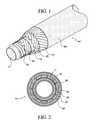
- FIG. 1is an isometric view of an embodiment of the invention showing the outside of the layers of the free venting pipe with a supplemental anti-extrusion layer.
- FIG. 2is a cross-sectional view of FIG. 1 .
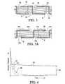
- FIG. 3is a cross-sectional view of stacked tapes forming composite laminates and separated by z-tapes.
- FIG. 3 ais a cross-sectional view of stacked tapes forming composite laminates and separated by s-tapes.
- FIG. 4is a set of graphs showing a comparison of the potential annulus pressure acting on the inner core of a conventional flexible pipe without the current inventive free venting pipe to the maximum differential pressure acting on an inner core of the current inventive free venting pipe.
- the letter A- 1generally refers to a free venting pipe of the current invention.
- the tubular core 11is typically wrapped with a hoop reinforcement layer 12 .
- the hoop reinforcement layer 12is shown covered with an anti-extrusion layer 16 .
- the anti-extrusion layer 16helps to bridge gaps formed in the hoop reinforcement layer 12 when the free venting pipe A- 1 is bent, thereby preventing the membrane 19 layer from extruding through the gaps formed in the hoop reinforcement layer 12 .
- the anti-extrusion layeris typically formed from a single layer of glass-reinforced tape, but multiple layers or alternative materials may be used, so long as they are pressure resistant to prevent the impermeable membrane 19 from being forced between the gaps that can form in the hoop reinforcement layer 12 .
- a layer of glass-reinforced tapemay be alternated with a layer of polyester (such as Mylar®), or polyamide, or other polymer.
- An impermeable membrane 19is shown extruded outside of the anti-extrusion layer 16 .
- Tensile reinforcement layers 20 , 21are typically helically wound around the membrane 19 .
- a jacket extrusion 24is then extruded outside of the tensile reinforcement layers 20 , 21 .
- the jacket extrusion 24is perforated to allow fluid pressure or gas to pass through the jacket extrusion 24 , and through the tensile reinforcement layers 20 , 21 .
- the tubular core 11 and the jacket extrusion 24are perforated to allow gas pressure to permeate through the layers to the membrane 19 .
- sets of four 1 ⁇ 8′′ holesare provided circumferentially, evenly spaced around the tubular core 11 and the jacket extrusion 24 .
- the setsare spaced approximately 6′′ apart along the length of the tubular core 11 and the jacket extrusion 24 .
- Other sizes of perforations and a different quantity of perforations and spacesmay also be provided.
- the anti-extrusion layer 16may be omitted.
- a lubricated layerthat is typically a wrapped tape made of tensilized polyethylene or polyamide or other polymer can instead be wrapped around the hoop layer 12 in place of the anti-extrusion layer 16 .
- the lubricated layerhelps to prevent the layers that are being separated by the lubricated layer from sticking to one another.
- the lubricated layermay also comprise an extruded jacked constructed of polyamide or other low friction material.
- a lubricated layermay also be used between other layers of the free venting pipe A- 1 as desired, to provide a separation and anti-stick layer.
- the hoop reinforcement layer 12 and the tensile reinforcement layers 20 , 21are comprised of a composite laminate construction as is disclosed in U.S. Pat. Nos. 6,804,942 and 6,491,779.
- individual tape strips 32are stacked together and each resulting composite laminate B is separated from the other composite laminate B by a z-tape 34 .
- the resulting composite laminatecan also be separated from another composite laminate B by an s-tape 34 a as shown in FIG. 3 a .
- the use of a z-tape 34 or s-tape 34 adepends upon the direction of wrapping of the composite laminate layer.
- the z-tape 34will be used when wrapping in one direction, while the s-tape 34 a will be used when wrapping in the opposite direction.
- the tape strips 32are typically bonded together with epoxy or resin and the z-tape or s-tape keeps the composite laminates 32 from bonding to each other as they cure.
- the tape strips 32may also be unbonded.
- the composite laminates Bare not pressure tight, and allow pressure to pass around the composite laminates B through the gaps 35 ( FIG. 3) and 35 a ( FIG. 3 a ) to the impermeable membrane 19 .
- multiple tensile layers, multiple hoop layers and/or multiple anti-extrusion, or extrusion layersmay also be provided, so long as each of the layers provided is permeable to gas and a single impermeable membrane is provided outside of a permeable core.
- the single impermeable membranemay be of a co-extruded multiple layer construction or may otherwise be formed such that a unitary impermeable layer is provided.
- a layermay be added to provide weighting to a desired length or lengths of the free venting pipe A- 1 . For example, weighting could be added to the inventive pipe to form a catenary, as shown in U.S. Pat. No. 7,073,978 to Michael J. Bryant.
- FIG. 4provides graphs that show a comparison of the potential annulus pressure acting on the inner core of a conventional flexible pipe without the current inventive free venting pipe to the maximum differential pressure acting on an inner core of the current inventive free venting pipe A- 1 .
- the Annulus Pressureis shown on the y-axis and Time is shown on the x-axis.
- the annulus pressureis that pressure that builds up between non-permeable or semi-permeable layers of conventional, flexible pipe.
- Curve 44shows the relative pressure of the bore of either a conventional, flexible pipe or the inventive free venting pipe A- 1 .
- Curve 45graphically shows the relatively high annulus pressure that can potentially develop in a conventional, flexible pipe.
- Curve 45The relatively high annulus pressure shown in Curve 45 will be acting on the outside of the inner core of the conventional, flexible pipe and therefore the high pressure must be counteracted with either an inner metal carcass or other hoop reinforcement must be provided to prevent the inward collapse of the core.
- Curve 42graphically shows the relatively low pressure outside core 11 of the inventive free venting pipe A- 1 .
- the differential pressure 46is the difference between the pressure in the bore of the inventive free venting pipe A- 1 and the pressure outside of the core 11 .
- the pressure difference 48graphically shows the relative potential between the annulus of a conventional, flexible pipe and the pressure of the inventive free venting pipe A- 1 . It is evident from the Annulus Pressure versus Time curves in FIG. 4 that the inventive free venting pipe A- 1 reduces the resulting or potential annulus pressure on the core 11 to thereby reduce the need for additional hoop layers or other hoop reinforcement to add strength to the inner core of a conventional, flexible pipe.
Landscapes
- Engineering & Computer Science (AREA)
- Mechanical Engineering (AREA)
- General Engineering & Computer Science (AREA)
- Rigid Pipes And Flexible Pipes (AREA)
- Laminated Bodies (AREA)
- Extrusion Moulding Of Plastics Or The Like (AREA)
- Separation Using Semi-Permeable Membranes (AREA)
Abstract
Description
Claims (8)
Priority Applications (10)
| Application Number | Priority Date | Filing Date | Title |
|---|---|---|---|
| US11/640,340US8714204B2 (en) | 2006-12-18 | 2006-12-18 | Free venting pipe and method of manufacture |
| AU2007334635AAU2007334635A1 (en) | 2006-12-18 | 2007-10-26 | Free venting pipe and method of manufacture |
| MX2009006499AMX2009006499A (en) | 2006-12-18 | 2007-10-26 | Free venting pipe and method of manufacture. |
| EP07861530AEP2095000A4 (en) | 2006-12-18 | 2007-10-26 | Free venting pipe and method of manufacture |
| CN200780046821ACN101663528A (en) | 2006-12-18 | 2007-10-26 | Free venting pipe and method of manufacture |
| CA002673027ACA2673027A1 (en) | 2006-12-18 | 2007-10-26 | Free venting pipe and method of manufacture |
| EA200970602AEA200970602A1 (en) | 2006-12-18 | 2007-10-26 | PIPE WITH FREE RELEASE AND ITS MANUFACTURING METHOD |
| PCT/US2007/022707WO2008076173A2 (en) | 2006-12-18 | 2007-10-26 | Free venting pipe and method of manufacture |
| BRPI0720520-1ABRPI0720520A2 (en) | 2006-12-18 | 2007-10-26 | FREE VENTILATION PIPING AND METHOD OF MANUFACTURING |
| NO20092620ANO20092620L (en) | 2006-12-18 | 2009-07-09 | Freely ventilating rudder and method of manufacture |
Applications Claiming Priority (1)
| Application Number | Priority Date | Filing Date | Title |
|---|---|---|---|
| US11/640,340US8714204B2 (en) | 2006-12-18 | 2006-12-18 | Free venting pipe and method of manufacture |
Publications (2)
| Publication Number | Publication Date |
|---|---|
| US20080145583A1 US20080145583A1 (en) | 2008-06-19 |
| US8714204B2true US8714204B2 (en) | 2014-05-06 |
Family
ID=39527646
Family Applications (1)
| Application Number | Title | Priority Date | Filing Date |
|---|---|---|---|
| US11/640,340Expired - Fee RelatedUS8714204B2 (en) | 2006-12-18 | 2006-12-18 | Free venting pipe and method of manufacture |
Country Status (10)
| Country | Link |
|---|---|
| US (1) | US8714204B2 (en) |
| EP (1) | EP2095000A4 (en) |
| CN (1) | CN101663528A (en) |
| AU (1) | AU2007334635A1 (en) |
| BR (1) | BRPI0720520A2 (en) |
| CA (1) | CA2673027A1 (en) |
| EA (1) | EA200970602A1 (en) |
| MX (1) | MX2009006499A (en) |
| NO (1) | NO20092620L (en) |
| WO (1) | WO2008076173A2 (en) |
Cited By (5)
| Publication number | Priority date | Publication date | Assignee | Title |
|---|---|---|---|---|
| US20160097472A1 (en)* | 2014-10-03 | 2016-04-07 | Hose Master, Llc | Fluid permeable hose carcass |
| US20170254446A1 (en)* | 2014-09-02 | 2017-09-07 | National Oilwell Varco Denmark I/S | Unbonded flexible pipe |
| US20180280650A1 (en)* | 2017-03-31 | 2018-10-04 | Koninklijke Philips N.V. | Moisture wicking conduit and system |
| US11231132B2 (en)* | 2017-01-13 | 2022-01-25 | National Oilwell Vareo Denmark I/S | Unbonded flexible pipe |
| US20220325828A1 (en)* | 2019-10-11 | 2022-10-13 | The Yokohama Rubber Co., Ltd. | Hydrogen-filling hose |
Families Citing this family (13)
| Publication number | Priority date | Publication date | Assignee | Title |
|---|---|---|---|---|
| FR2934348B1 (en) | 2008-07-28 | 2010-08-20 | Technip France | METHOD AND INSTALLATION FOR CONSTRUCTING A LAYER OF ARMOR YARN |
| US8967205B2 (en)* | 2010-03-17 | 2015-03-03 | Deepflex Inc. | Anti-extrusion layer with non-interlocked gap controlled hoop strength layer |
| BR112012026359A2 (en)* | 2010-04-14 | 2016-07-19 | Deepflex Inc | radiation cured reinforcement cells |
| CA2805315A1 (en)* | 2010-07-14 | 2012-01-19 | National Oilwell Varco Denmark I/S | An unbonded flexible pipe |
| CN103228972B (en)* | 2010-09-30 | 2015-06-24 | 迪普弗莱克斯有限公司 | Improved reinforcement stack |
| EP2707635A4 (en)* | 2011-05-13 | 2014-11-12 | Deepflex Inc | Reinforcement laminate having an alignment feature |
| DE102012208091A1 (en)* | 2011-12-16 | 2013-06-20 | Contitech Antriebssysteme Gmbh | Elastic article, in particular drive belt |
| GB201122437D0 (en)* | 2011-12-29 | 2012-02-08 | Wellstream Int Ltd | Flexible pipe body and method of manufacture |
| EP2859173B1 (en)* | 2012-06-06 | 2019-03-20 | National Oilwell Varco Denmark I/S | A riser and an offshore system |
| EP2861903A1 (en)* | 2012-06-15 | 2015-04-22 | DeepFlex Inc. | Pressure armor with integral anti-collapse layer |
| US9482373B2 (en) | 2012-07-06 | 2016-11-01 | National Oilwell Varco Denmark I/S | Unbonded flexible pipe |
| GB201611246D0 (en)* | 2016-06-29 | 2016-08-10 | Ge Oil & Gas Uk Ltd | Gas venting |
| US11739864B2 (en)* | 2021-02-24 | 2023-08-29 | Parker-Hannifin Corporation | Hose having a tensile strength braided layer |
Citations (39)
| Publication number | Priority date | Publication date | Assignee | Title |
|---|---|---|---|---|
| US3420276A (en) | 1965-07-22 | 1969-01-07 | Hewitt Robins Inc | Gas permeable flexible hose |
| GB1207065A (en) | 1967-05-29 | 1970-09-30 | United Aircraft Corp | Method and apparatus for the production of continuous tape |
| US3830261A (en) | 1972-06-22 | 1974-08-20 | Mc Donnell Douglas Corp | Self-sealing hollow body for containing fluids |
| US3933554A (en)* | 1973-06-13 | 1976-01-20 | Treg S.P.A. | Process for manufacturing flexible hoses of elastomeric material having a cavity wall |
| US4096888A (en) | 1975-07-07 | 1978-06-27 | The Gates Rubber Company | Halogenated butyl interlayer for reinforced elastomeric hose articles |
| US4344462A (en) | 1979-05-30 | 1982-08-17 | Coflexip | Flexible tubular conduit |
| US4402346A (en) | 1978-03-14 | 1983-09-06 | Dunlop Limited | Crude oil pipe having layers of graduated permeability to hydrogen sulfide |
| US4606410A (en) | 1983-04-06 | 1986-08-19 | Bst Lift Systems, Inc. | Subsurface safety system |
| US4657049A (en) | 1972-10-12 | 1987-04-14 | Georges Fourty | Tubular body composed of reinforced thermosetting polymer |
| US4800958A (en) | 1986-08-07 | 1989-01-31 | Halliburton Company | Annulus pressure operated vent assembly |
| US4929478A (en) | 1988-06-17 | 1990-05-29 | The Bentley-Harris Manufacturing Company | Protective fabric sleeves |
| US5264262A (en) | 1991-08-30 | 1993-11-23 | Tokai Rubber Industries, Inc. | Refrigerant transporting hose having inner tube including resin layer |
| US5275209A (en) | 1988-05-09 | 1994-01-04 | Institut Francais Du Petrole | Hose including an aluminum alloy |
| US5669420A (en) | 1990-07-27 | 1997-09-23 | Coflexip | Casing and flexible tubular conduit comprising such a casing and process for producing it |
| US5730188A (en) | 1996-10-11 | 1998-03-24 | Wellstream, Inc. | Flexible conduit |
| EP0903527A1 (en) | 1997-09-18 | 1999-03-24 | Institut Francais Du Petrole | Structure of a flexible conduit comprising a continuous interior pipe made of metal |
| US6039083A (en)* | 1998-10-13 | 2000-03-21 | Wellstream, Inc. | Vented, layered-wall deepwater conduit and method |
| US6062269A (en) | 1996-02-20 | 2000-05-16 | Kabushiki Kaisha Meiji Gomu Kasei | Refrigerant conveying hose |
| US6220079B1 (en) | 1998-07-22 | 2001-04-24 | Safety Liner Systems, L.L.C. | Annular fluid manipulation in lined tubular systems |
| US6253855B1 (en) | 1999-01-21 | 2001-07-03 | Mentor Subsea Technology Services, Inc. | Intelligent production riser |
| US6338365B1 (en) | 1997-09-18 | 2002-01-15 | Institut Francais Du Petrole | Flexible piping structure having a continuous metal inner tube |
| US6401760B2 (en) | 1999-12-17 | 2002-06-11 | Coflexip | Subsea flexible pipe of long length and modular structure |
| US6446672B1 (en)* | 1999-11-05 | 2002-09-10 | Wellstream, Inc. | Flexible pipe including vent passage and method of manufacturing same |
| US6491779B1 (en) | 1999-05-03 | 2002-12-10 | Deepsea Flexibles, Inc. | Method of forming a composite tubular assembly |
| US20020185188A1 (en) | 2001-04-27 | 2002-12-12 | Quigley Peter A. | Composite tubing |
| US20030056845A1 (en) | 1999-11-05 | 2003-03-27 | Wellstream, Inc. | Flexible pipe including a vent passage and method of manufacturing same |
| US20030121559A1 (en) | 2000-01-14 | 2003-07-03 | Kristian Glejbol | Armoured, flexible pipe and use of same |
| US20030131899A1 (en) | 2000-09-29 | 2003-07-17 | Hiroki Baba | Thin-walled rubber hose and method of producing the same |
| US20030159745A1 (en) | 2000-05-10 | 2003-08-28 | Philippe Espinasse | Flexible pipe with wire or strip winding for maintaining armours |
| US20030178084A1 (en) | 2002-03-21 | 2003-09-25 | Yves Charron | Pipe comprising a porous inner wall |
| US6631743B2 (en) | 1998-08-13 | 2003-10-14 | Aeroquip-Vickers International Gmbh | Flexible cord-like hollow object |
| US20040040609A1 (en)* | 2002-08-30 | 2004-03-04 | The Yokohama Rubber Co., Ltd. | Ultra-low permeation hose and method of manufacture |
| US20040175523A1 (en) | 2001-08-14 | 2004-09-09 | Jean-Michel Gerez | Flat textile strip forming one layer of a flexible duct that is used for hydrocarbon transport and the duct thus formed |
| US20050189029A1 (en) | 2004-02-27 | 2005-09-01 | Fiberspar Corporation | Fiber reinforced spoolable pipe |
| US20050224127A1 (en) | 2000-12-22 | 2005-10-13 | Wilson Alexander B | Compound pipe |
| US20060130924A1 (en)* | 2003-06-11 | 2006-06-22 | Francois Dupoiron | Flexible tubular duct for the transport of fluid and particularly gaseous hydrocarbons with an anti-turbulence carcass and internal lining |
| US20060145479A1 (en) | 2002-07-25 | 2006-07-06 | Mcintyre Stuart | Pipe liner connector |
| US7073978B2 (en) | 2004-08-16 | 2006-07-11 | Deepflex, Inc. | Lightweight catenary system |
| US20060249215A1 (en)* | 2005-05-06 | 2006-11-09 | Bryant Michael J | Anti-collapse system and method of manufacture |
- 2006
- 2006-12-18USUS11/640,340patent/US8714204B2/ennot_activeExpired - Fee Related
- 2007
- 2007-10-26CNCN200780046821Apatent/CN101663528A/enactivePending
- 2007-10-26AUAU2007334635Apatent/AU2007334635A1/ennot_activeAbandoned
- 2007-10-26MXMX2009006499Apatent/MX2009006499A/ennot_activeApplication Discontinuation
- 2007-10-26CACA002673027Apatent/CA2673027A1/ennot_activeAbandoned
- 2007-10-26BRBRPI0720520-1Apatent/BRPI0720520A2/ennot_activeApplication Discontinuation
- 2007-10-26WOPCT/US2007/022707patent/WO2008076173A2/enactiveApplication Filing
- 2007-10-26EPEP07861530Apatent/EP2095000A4/ennot_activeWithdrawn
- 2007-10-26EAEA200970602Apatent/EA200970602A1/enunknown
- 2009
- 2009-07-09NONO20092620Apatent/NO20092620L/ennot_activeApplication Discontinuation
Patent Citations (45)
| Publication number | Priority date | Publication date | Assignee | Title |
|---|---|---|---|---|
| US3420276A (en) | 1965-07-22 | 1969-01-07 | Hewitt Robins Inc | Gas permeable flexible hose |
| GB1207065A (en) | 1967-05-29 | 1970-09-30 | United Aircraft Corp | Method and apparatus for the production of continuous tape |
| US3830261A (en) | 1972-06-22 | 1974-08-20 | Mc Donnell Douglas Corp | Self-sealing hollow body for containing fluids |
| US4657049A (en) | 1972-10-12 | 1987-04-14 | Georges Fourty | Tubular body composed of reinforced thermosetting polymer |
| US3933554A (en)* | 1973-06-13 | 1976-01-20 | Treg S.P.A. | Process for manufacturing flexible hoses of elastomeric material having a cavity wall |
| US4096888A (en) | 1975-07-07 | 1978-06-27 | The Gates Rubber Company | Halogenated butyl interlayer for reinforced elastomeric hose articles |
| US4402346A (en) | 1978-03-14 | 1983-09-06 | Dunlop Limited | Crude oil pipe having layers of graduated permeability to hydrogen sulfide |
| US4344462A (en) | 1979-05-30 | 1982-08-17 | Coflexip | Flexible tubular conduit |
| US4606410A (en) | 1983-04-06 | 1986-08-19 | Bst Lift Systems, Inc. | Subsurface safety system |
| US4800958A (en) | 1986-08-07 | 1989-01-31 | Halliburton Company | Annulus pressure operated vent assembly |
| US5275209A (en) | 1988-05-09 | 1994-01-04 | Institut Francais Du Petrole | Hose including an aluminum alloy |
| US5406984A (en) | 1988-05-09 | 1995-04-18 | Institut Francais Du Petrole | Hose including an aluminum alloy |
| US4929478A (en) | 1988-06-17 | 1990-05-29 | The Bentley-Harris Manufacturing Company | Protective fabric sleeves |
| US5669420A (en) | 1990-07-27 | 1997-09-23 | Coflexip | Casing and flexible tubular conduit comprising such a casing and process for producing it |
| US5264262A (en) | 1991-08-30 | 1993-11-23 | Tokai Rubber Industries, Inc. | Refrigerant transporting hose having inner tube including resin layer |
| US6062269A (en) | 1996-02-20 | 2000-05-16 | Kabushiki Kaisha Meiji Gomu Kasei | Refrigerant conveying hose |
| US5730188A (en) | 1996-10-11 | 1998-03-24 | Wellstream, Inc. | Flexible conduit |
| US6338365B1 (en) | 1997-09-18 | 2002-01-15 | Institut Francais Du Petrole | Flexible piping structure having a continuous metal inner tube |
| US6098667A (en) | 1997-09-18 | 2000-08-08 | Institut Francais Du Petrole | Flexible piping structure having a continuous metal inner tube |
| EP0903527A1 (en) | 1997-09-18 | 1999-03-24 | Institut Francais Du Petrole | Structure of a flexible conduit comprising a continuous interior pipe made of metal |
| US6220079B1 (en) | 1998-07-22 | 2001-04-24 | Safety Liner Systems, L.L.C. | Annular fluid manipulation in lined tubular systems |
| US6631743B2 (en) | 1998-08-13 | 2003-10-14 | Aeroquip-Vickers International Gmbh | Flexible cord-like hollow object |
| US6039083A (en)* | 1998-10-13 | 2000-03-21 | Wellstream, Inc. | Vented, layered-wall deepwater conduit and method |
| US6253855B1 (en) | 1999-01-21 | 2001-07-03 | Mentor Subsea Technology Services, Inc. | Intelligent production riser |
| US20030026928A1 (en)* | 1999-05-03 | 2003-02-06 | Bryant Michael J. | Composite tubular assembly and method of forming same |
| US6804942B2 (en) | 1999-05-03 | 2004-10-19 | Michael J. Bryant | Composite tubular assembly and method of forming same |
| US6491779B1 (en) | 1999-05-03 | 2002-12-10 | Deepsea Flexibles, Inc. | Method of forming a composite tubular assembly |
| US6446672B1 (en)* | 1999-11-05 | 2002-09-10 | Wellstream, Inc. | Flexible pipe including vent passage and method of manufacturing same |
| US20030056845A1 (en) | 1999-11-05 | 2003-03-27 | Wellstream, Inc. | Flexible pipe including a vent passage and method of manufacturing same |
| US6401760B2 (en) | 1999-12-17 | 2002-06-11 | Coflexip | Subsea flexible pipe of long length and modular structure |
| US20030121559A1 (en) | 2000-01-14 | 2003-07-03 | Kristian Glejbol | Armoured, flexible pipe and use of same |
| US6978806B2 (en) | 2000-01-14 | 2005-12-27 | Nkt Flexible I/S | Armored, flexible pipe and use of same |
| US20030159745A1 (en) | 2000-05-10 | 2003-08-28 | Philippe Espinasse | Flexible pipe with wire or strip winding for maintaining armours |
| US20030131899A1 (en) | 2000-09-29 | 2003-07-17 | Hiroki Baba | Thin-walled rubber hose and method of producing the same |
| US20050224127A1 (en) | 2000-12-22 | 2005-10-13 | Wilson Alexander B | Compound pipe |
| US20020185188A1 (en) | 2001-04-27 | 2002-12-12 | Quigley Peter A. | Composite tubing |
| US20070125439A1 (en) | 2001-04-27 | 2007-06-07 | Quigley Peter A | Composite tubing |
| US20040175523A1 (en) | 2001-08-14 | 2004-09-09 | Jean-Michel Gerez | Flat textile strip forming one layer of a flexible duct that is used for hydrocarbon transport and the duct thus formed |
| US20030178084A1 (en) | 2002-03-21 | 2003-09-25 | Yves Charron | Pipe comprising a porous inner wall |
| US20060145479A1 (en) | 2002-07-25 | 2006-07-06 | Mcintyre Stuart | Pipe liner connector |
| US20040040609A1 (en)* | 2002-08-30 | 2004-03-04 | The Yokohama Rubber Co., Ltd. | Ultra-low permeation hose and method of manufacture |
| US20060130924A1 (en)* | 2003-06-11 | 2006-06-22 | Francois Dupoiron | Flexible tubular duct for the transport of fluid and particularly gaseous hydrocarbons with an anti-turbulence carcass and internal lining |
| US20050189029A1 (en) | 2004-02-27 | 2005-09-01 | Fiberspar Corporation | Fiber reinforced spoolable pipe |
| US7073978B2 (en) | 2004-08-16 | 2006-07-11 | Deepflex, Inc. | Lightweight catenary system |
| US20060249215A1 (en)* | 2005-05-06 | 2006-11-09 | Bryant Michael J | Anti-collapse system and method of manufacture |
Non-Patent Citations (5)
| Title |
|---|
| Chinese Office Action dated Jul. 19, 2010, in corresponding Chinese Patent Application No. 200780046821.7. 6 pages. |
| Coflexip Subsea & Topside Jumper Products Brochure, 4 pages, Oct. 2004. |
| Extended European Search Report Issued in European Application No. 07861530.9; Dated Aug. 16, 2012 (9 Pages). |
| MCS Advanced Engineering Solutions Data Sheet, 2 pages, Oct. 2005. |
| PCT Notification of Transmittal of International Preliminary Report on Patentability issued for international application No. PCT/US07/22707, mailed on Aug. 3, 2009, 12 pages. |
Cited By (9)
| Publication number | Priority date | Publication date | Assignee | Title |
|---|---|---|---|---|
| US20170254446A1 (en)* | 2014-09-02 | 2017-09-07 | National Oilwell Varco Denmark I/S | Unbonded flexible pipe |
| US20160097472A1 (en)* | 2014-10-03 | 2016-04-07 | Hose Master, Llc | Fluid permeable hose carcass |
| US10203053B2 (en)* | 2014-10-03 | 2019-02-12 | Hose Master Llc | Fluid permeable hose carcass |
| US11028946B2 (en) | 2014-10-03 | 2021-06-08 | Hose Master, Llc | Fluid permeable hose carcass |
| US11231132B2 (en)* | 2017-01-13 | 2022-01-25 | National Oilwell Vareo Denmark I/S | Unbonded flexible pipe |
| US20180280650A1 (en)* | 2017-03-31 | 2018-10-04 | Koninklijke Philips N.V. | Moisture wicking conduit and system |
| US10953185B2 (en)* | 2017-03-31 | 2021-03-23 | Koninklijke Philips N.V. | Moisture wicking conduit and system |
| US20220325828A1 (en)* | 2019-10-11 | 2022-10-13 | The Yokohama Rubber Co., Ltd. | Hydrogen-filling hose |
| US11746933B2 (en)* | 2019-10-11 | 2023-09-05 | The Yokohama Rubber Co., Ltd | Hydrogen-filling hose |
Also Published As
| Publication number | Publication date |
|---|---|
| MX2009006499A (en) | 2009-09-09 |
| WO2008076173A3 (en) | 2008-08-07 |
| AU2007334635A1 (en) | 2008-06-26 |
| CN101663528A (en) | 2010-03-03 |
| EP2095000A2 (en) | 2009-09-02 |
| CA2673027A1 (en) | 2008-06-26 |
| BRPI0720520A2 (en) | 2014-01-07 |
| US20080145583A1 (en) | 2008-06-19 |
| EA200970602A1 (en) | 2010-02-26 |
| NO20092620L (en) | 2009-07-09 |
| EP2095000A4 (en) | 2012-09-12 |
| WO2008076173A2 (en) | 2008-06-26 |
Similar Documents
| Publication | Publication Date | Title |
|---|---|---|
| US8714204B2 (en) | Free venting pipe and method of manufacture | |
| AU2008257278B2 (en) | Flexible tubular pipe for transporting gaseous hydrocarbons | |
| EP2870397B1 (en) | An unbonded flexible pipe | |
| US8960239B2 (en) | Unbonded flexible pipe | |
| US20130014849A1 (en) | Flexible unbonded pipe and an offshore system | |
| US11149894B2 (en) | Gas venting | |
| WO2006121525A2 (en) | Anti-collapse system and method of manufacture | |
| US6679298B2 (en) | Collapsible flexible pipe | |
| US20120273080A1 (en) | Flexible pipe and a method of producing a flexible pipe | |
| US9482372B2 (en) | Flexible unbonded pipe | |
| DK3004709T3 (en) | Flexible conduit for transport of fluid, its use and associated method | |
| US20060144456A1 (en) | Umbilical for offshore/reduction of hydrocarbons | |
| US6978843B2 (en) | Well configuration and method of increasing production from a hydrocarbon well | |
| US20030178201A1 (en) | Method for inserting a pipe liner | |
| WO2013098553A1 (en) | Flexible pipe body and method of manufacture | |
| US20040035485A1 (en) | Method of binding polyphenylene sulfide with polyamide and products made thereof | |
| EP3042112A1 (en) | A flexible pipe | |
| Bryant et al. | Nonmetallic unbonded flexible pipes for deep water | |
| JP6895370B2 (en) | hose | |
| GB2502772A (en) | Tubular conduit | |
| WO2018233790A1 (en) | FLEXIBLE PIPE AND METHOD OF EQUALIZING THE PRESSURE OF A FLEXIBLE PIPE | |
| Bhat et al. | Nonmetallic Unbonded Flexible Pipes for Deep Water |
Legal Events
| Date | Code | Title | Description |
|---|---|---|---|
| AS | Assignment | Owner name:DEEPFLEX INC., TEXAS Free format text:ASSIGNMENT OF ASSIGNORS INTEREST;ASSIGNOR:BRYANT, MICHAEL J.;REEL/FRAME:018718/0532 Effective date:20061215 | |
| AS | Assignment | Owner name:DEEPFLEX INC., TEXAS Free format text:ASSIGNMENT OF ASSIGNORS INTEREST;ASSIGNOR:BRYANT, MICHAEL J.;REEL/FRAME:023024/0257 Effective date:20090721 | |
| AS | Assignment | Owner name:COMERICA BANK, CALIFORNIA Free format text:SECURITY AGREEMENT;ASSIGNOR:DEEPFLEX, INC.;REEL/FRAME:028715/0022 Effective date:20120731 | |
| STCF | Information on status: patent grant | Free format text:PATENTED CASE | |
| MAFP | Maintenance fee payment | Free format text:PAYMENT OF MAINTENANCE FEE, 4TH YR, SMALL ENTITY (ORIGINAL EVENT CODE: M2551) Year of fee payment:4 | |
| LAPS | Lapse for failure to pay maintenance fees | Free format text:PATENT EXPIRED FOR FAILURE TO PAY MAINTENANCE FEES (ORIGINAL EVENT CODE: EXP.); ENTITY STATUS OF PATENT OWNER: SMALL ENTITY | |
| FEPP | Fee payment procedure | Free format text:MAINTENANCE FEE REMINDER MAILED (ORIGINAL EVENT CODE: REM.); ENTITY STATUS OF PATENT OWNER: SMALL ENTITY | |
| STCH | Information on status: patent discontinuation | Free format text:PATENT EXPIRED DUE TO NONPAYMENT OF MAINTENANCE FEES UNDER 37 CFR 1.362 | |
| FP | Lapsed due to failure to pay maintenance fee | Effective date:20220506 |