US8714011B2 - Snap-fit measuring container - Google Patents
Snap-fit measuring containerDownload PDFInfo
- Publication number
- US8714011B2 US8714011B2US13/537,590US201213537590AUS8714011B2US 8714011 B2US8714011 B2US 8714011B2US 201213537590 AUS201213537590 AUS 201213537590AUS 8714011 B2US8714011 B2US 8714011B2
- Authority
- US
- United States
- Prior art keywords
- handle
- measuring
- rib
- measuring container
- channel
- Prior art date
- Legal status (The legal status is an assumption and is not a legal conclusion. Google has not performed a legal analysis and makes no representation as to the accuracy of the status listed.)
- Active, expires
Links
Images


Classifications
- G—PHYSICS
- G01—MEASURING; TESTING
- G01F—MEASURING VOLUME, VOLUME FLOW, MASS FLOW OR LIQUID LEVEL; METERING BY VOLUME
- G01F19/00—Calibrated capacity measures for fluids or fluent solid material, e.g. measuring cups
- G—PHYSICS
- G01—MEASURING; TESTING
- G01F—MEASURING VOLUME, VOLUME FLOW, MASS FLOW OR LIQUID LEVEL; METERING BY VOLUME
- G01F19/00—Calibrated capacity measures for fluids or fluent solid material, e.g. measuring cups
- G01F19/002—Measuring spoons or scoops
Definitions
- the present inventionrelates to measuring cups and measuring spoons.
- Measuring cups and measuring spoonsare commonly provided in a set in which an array of differently-sized cups or spoons are provided.
- the cups or spoonsare typically stackable for more compact storage. Though stackable, they are not held in place and tend to separate from one another readily upon opening a drawer in which they are stored.
- Measuring spoonsare sometimes configured with a ring that permanently connects the array of spoons together. Though this ensures that each of the spoons can be readily located together with the others, it can be cumbersome and requires the user to hold all of the spoons together in use. It also requires all of them to be washed together, even if otherwise unnecessary for some of the spoons.
- the present inventionincludes a measuring cup or spoon having a handle and a measuring container.
- the handle of a first measuring cupincludes a feature that interacts with a complementary feature on the handle of a second measuring cup to secure the first and second cups together.
- a ribextends downward from the handle of the first cup and is received within a channel formed in the handle of the second cup.
- the rib and channelare sized such that the two cups are frictionally held together.
- a set of several measuring cupsis provided in which each one of the cups includes a handle having a similar fastening feature.
- FIG. 1is a top perspective view of a preferred measuring cup.
- FIG. 2is a bottom perspective view of a preferred measuring cup.
- FIG. 3is a top plan view of a preferred measuring cup.
- FIG. 4is a side view of a preferred measuring cup.
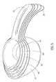
- FIG. 5is a top perspective view of a preferred set of measuring cups, shown nested together.
- FIG. 6is a perspective view of an alternate preferred set of measuring cups, shown separated from one another.
- FIG. 7is a top view of the set of measuring cups of FIG. 6 , shown nested together.
- FIG. 8is a side sectional view of the set of measuring cups of FIG. 7 , taken along line A-A of FIG. 7 .
- a preferred measuring container 10includes a measuring vessel 20 and a handle 30 .
- the measuring vesselis in the form of a measuring cup.
- the measuring vesselhas a nominal or predetermined volume such as 3 ⁇ 4 cup.
- measuring cups of other sizesmay also be formed in accordance with the invention, including for example cups having vessels with volumes of 1 ⁇ 4 cup, 1 ⁇ 3 cup, 1 ⁇ 2 cup, 2 ⁇ 3 cup, or other particular volumes.
- the same principles of the inventionare also applicable to measuring devices having smaller measuring vessels, such as measuring spoons.
- the measuring spoonsmay have volumes such as 1 ⁇ 8 teaspoon, 1 ⁇ 4 teaspoon, 1 ⁇ 2 teaspoon, 1 teaspoon, 1 tablespoon, or other volumes.
- the preferred vessel 20includes a floor having sidewalls 24 extending upward and terminating in a rim 22 .
- the flooris substantially flat along at least a portion of its surface, though the bottom portion of the vessel may have any shape.
- the vesselpreferably is formed with a known volume in order to serve as a measuring cup or spoon. The vessel may, however, have an indeterminate or less precise volume.
- the vesselincludes a handle 30 extending laterally away from the vessel. Most preferably a proximal end 32 of the handle is attached to the vessel substantially at the rim 22 of the vessel, though the handle may alternatively be secured to the vessel at a different location such as along the sidewalls at a location below the rim.
- the handleextends laterally away from the vessel, terminating in a distal end 34 of the handle.
- the handleincludes a feature for connecting the handle of a first cup to the handle of a second cup having a mating feature.
- the lower side 35 of the handleincludes a downwardly-depending rib 36 .
- the ribprojects substantially vertically downward from the handle, in a direction substantially perpendicular to the lower side of the handle.
- the rib 36is elongated, having a length (in the direction from the proximal end of the handle toward the distal end of the handle) that is much greater than the width of the rib.
- the length of the ribis approximately half the length of the handle.
- the ribmay be much smaller, such as 1 ⁇ 3 or 1 ⁇ 4 of the length of the handle.
- the ribmay be longer and may extend along the entire length of the handle.
- the ribextends in a direction that is generally parallel with the direction of the handle.
- the longest side of the ribis one that extends in a direction from the proximal end of the handle toward the distal end of the handle.
- the ribmay be substantially square in cross-section, having a length and width that are equal.
- the ribmay be wider than it is long, therefore being formed in a way that is generally perpendicular to the version as illustrated.
- the lateral rib as illustratedis preferred however, in part because it allows for a long rib with a large surface area of contact between the rib and mating surface of another measuring device, thereby providing a stronger connection between two devices.
- the nature of the rib and the handlesallows a user to separate them from one another readily, as described further below.
- an upper surface of the handleincludes a channel 38 .
- the channelis formed to receive the rib 36 of a mating measuring cup, and therefore has a depth, length, and width to allow the interconnection.
- the width of the channelis equal to or slightly less than that of the rib so that the rib will be frictionally and snugly received within the channel.
- the sidewalls of the rib and the channelare each substantially vertical, thereby relying on the snugness of the fit between the rib and the channel to provide a frictional force to hold two measuring devices together.
- the rib and the channelare each trapezoidal in cross section.
- the ribis somewhat narrower and then the sides of the rib flare outwardly somewhat to form a wider base.
- the opening of the channel adjacent the upper surface of the handleis narrower than the bottom surface of the channel, with the sidewalls of the channel flaring outwardly somewhat.
- the channelwidens to form a mouth 39 that is larger than the width of the opening of the channel along the rest of the length of the channel.
- the widened mouthfacilitates removal of the first device from the second device.
- the handle of the measuring devicemay curve downwardly in a direction from the rim toward the floor of the vessel as the handle extends laterally away from the proximal end toward the distal end.
- the handlemay be generally or completely flat or horizontal.
- a set of several measuring devicesis provided.
- a set of five measuring cupsis provided together.
- Each measuring deviceincludes a vessel or cup 10 , 40 , 50 , 60 , 70 .
- Eachalso includes a corresponding handle (e.g., 30 , 72 ).
- the handle 30 of the largest cup 10has a sharper angle of curvature than the handle 72 of the smallest cup. This gradual reduction of curvature from the largest to the smallest aids in the nesting of the cups within one another.
- the handle lengths, together with the curvature,are preferably formed such that the handle 72 of the smallest cup is the shortest, with the handles within the set becoming progressively longer as the size of the cup increases.
- the handle 30 for the largest cup 10is the longest in the preferred version of the invention. As shown in FIG. 5 , this progressive curvature and increase in size of the invention allows the handle of each one of the separate cups to have a portion of its upper surface that is not covered by the handle of a cup nested within it. Consequently, intermediate sized cups are readily accessible and separable from the others by quickly grasping the exposed portion of the distal end of the desired cup.
- the width of the channel and the ribmust also increase as the size of the cups progresses in one direction or the other.
- the smallest measuring devicehas a rib and channel that is smaller than that of any of the others, with the largest measuring device having the largest rib and channel.
- Intermediate deviceshave ribs and channels that gradually increase in width from the smallest one to the largest one, with each individual rib being sized to be snugly received within the channel of the next-largest measuring device.
- the progression in sizes of channels and ribsmay be configured in the opposite way in other versions of the invention.
- the smallest measuring devicemay have the largest channel and rib while the largest measuring device having the smallest channel and rib.
- the intermediate devicesthen will have channels and ribs that decrease in size from the smallest vessel to the device having the largest vessel.
- each one of a set of measuring spoonsmay include a vessel that is smaller than the measuring cups.
- the measuring spoonshave predetermined volumes in fractions or multiples of teaspoons or tablespoons.
- the handles of the measuring spoonsare formed in accordance with the handles of the measuring cups as described above, each one of the handles having a feature for joining the handle to an adjacent handle of a measuring spoon of a different size.
- a set of measuring spoonspreferably has handles of varying curvature, with a smallest measuring spoon having a handle that is relatively flatter than the others and a largest measuring spoon having a handle that is relatively more curved than the others.
- the attachment featureis in the form of a rib and a channel, the rib being formed on the lower side and the channel being formed on the upper side of the handle.
- the ribmay extend upwardly from the upper side of the handle, thereby forming a channel within the lower surface of the handle.
- the rib and mating channelmay be formed on a handle surface such that they extend substantially laterally toward one another rather than vertically as in the examples primarily described above.
- FIGS. 6-8an alternate set of measuring cups is shown, in this case containing five cups 110 , 120 , 130 , 140 , 150 .
- the preferred cupincludes a front portion that may be inclined in the shape of a pouring spout and a rearward portion with a substantially vertical or otherwise upwardly extending sidewall.
- the rear sidewallis attached to a handle having a proximal lateral portion adjacent the rear sidewall and a distal portion extending away from the proximal portion, with a central angled portion between the distal and proximal portions.
- the central angled portionextends downward from the proximal portion at an angle of about 45 degrees or greater.
- the central sectionis angled downward at between about 30 degrees and 60 degrees with respect to the proximal portion. Thereafter the distal portion extends laterally away from the central portion.
- the distal portionmay be substantially horizontal, while in the illustrated version the distal portion is inclined slightly such that it terminates at a point at approximately the same height as that of the proximal portion.
- a first cup 150includes a rearward sidewall 151 that transitions to a proximal handle portion 152 , with a central handle portion 158 extending between the proximal handle portion 152 and distal handle portion 153 .
- a first rib 155is formed on the rear sidewall 151 along an outer surface adjacent the proximal portion of the handle.
- a second rib 156is formed on a lower surface of the central portion of the handle such that it projects inward, toward the first rib and the rear sidewall.
- the handle portionsdefine a width generally perpendicular to the length from the proximal portion to the distal portion.
- the ribmay extend across the entire width of the handle, while in other versions the rib may be narrower than the width of the handle.
- the channelmay extend across the entire width or may be narrower than the width of the handle.
- the channelneed not be recessed below the handle surfaced, but may be formed as a well between two adjacent raised surfaces.
- a second cup 140is formed with mating surface is configured to engage the first rib and the second rib of the first cup 150 .
- the second cup 140includes a rear sidewall 141 that transitions to a proximal handle portion 142 and terminates in a distal handle portion 143 , with a central handle portion between the proximal and distal handle portions.
- the second cupincludes a pair of inward-facing ribs, one formed on an outer surface of the rear sidewall and one formed on the lower surface of the central portion.
- the handle of the second cup 140includes a pair of channels configured to receive the pair of ribs formed on the first cup 150 .
- the second cupincludes a first channel 145 formed along the rear sidewall of the second cup and a second channel 146 formed on an upper surface of the central portion.
- the channels formed on the second cup 140are positioned such that they can snugly receive the ribs formed on the first cup 150 when the first cup is nested fully within the second cup as illustrated in FIG. 8 .
- the handleincludes a pair of ribs extending laterally inward and a pair of channels facing laterally outward.
- the top cup(which is the smallest) only includes an internal pair of inward facing ribs, while the bottom cup (which is the largest) only includes a pair of outward facing channels.
- the set as illustratedis configured such that five cups can be nested and secured together.
- an upper nesting cupincludes a first mating surface formed on an outer surface of the rear sidewall of the cup and a second mating surface formed on an inner surface of the angled central section of the handle.
- a lower nesting cupincludes a third mating surface formed on an inner surface of the rear sidewall of the cup and a fourth mating surface formed on an outer surface of the central section of the handle.
- the downward angled nature of the central section of the handlefurther serves to facilitate separation of the cups from one another.
- the central portion of the upper cupwill be urged laterally outward, away from the rear sidewall 151 of the upper cup, thereby disengaging the rib 156 from the channel 146 of the lower cup. This separation will allow the upper cup 150 to be readily removed from the lower cup 140 .
Landscapes
- Physics & Mathematics (AREA)
- Fluid Mechanics (AREA)
- General Physics & Mathematics (AREA)
- Table Devices Or Equipment (AREA)
- Details Of Rigid Or Semi-Rigid Containers (AREA)
Abstract
Description
Claims (9)
Priority Applications (1)
| Application Number | Priority Date | Filing Date | Title |
|---|---|---|---|
| US13/537,590US8714011B2 (en) | 2011-02-08 | 2012-06-29 | Snap-fit measuring container |
Applications Claiming Priority (2)
| Application Number | Priority Date | Filing Date | Title |
|---|---|---|---|
| US13/023,252US8806935B2 (en) | 2011-02-08 | 2011-02-08 | Snap-fit measuring container |
| US13/537,590US8714011B2 (en) | 2011-02-08 | 2012-06-29 | Snap-fit measuring container |
Related Parent Applications (1)
| Application Number | Title | Priority Date | Filing Date |
|---|---|---|---|
| US13/023,252Continuation-In-PartUS8806935B2 (en) | 2011-02-08 | 2011-02-08 | Snap-fit measuring container |
Publications (2)
| Publication Number | Publication Date |
|---|---|
| US20120273380A1 US20120273380A1 (en) | 2012-11-01 |
| US8714011B2true US8714011B2 (en) | 2014-05-06 |
Family
ID=47067075
Family Applications (1)
| Application Number | Title | Priority Date | Filing Date |
|---|---|---|---|
| US13/537,590Active2031-03-06US8714011B2 (en) | 2011-02-08 | 2012-06-29 | Snap-fit measuring container |
Country Status (1)
| Country | Link |
|---|---|
| US (1) | US8714011B2 (en) |
Cited By (5)
| Publication number | Priority date | Publication date | Assignee | Title |
|---|---|---|---|---|
| US20160067860A1 (en)* | 2014-09-10 | 2016-03-10 | Mark Prommel | Nesting Kitchen Knife Set |
| US10106296B2 (en) | 2016-01-08 | 2018-10-23 | Wki Holding Company, Inc. | Nesting cooking vessels |
| US20220061564A1 (en)* | 2020-09-02 | 2022-03-03 | Dart Container Corporation | Stackable cutlery |
| US20220160486A1 (en)* | 2020-11-26 | 2022-05-26 | Jui Yuan SHIH | Bone graft carrier |
| USD1061180S1 (en)* | 2023-04-26 | 2025-02-11 | World Centric | Scoop |
Families Citing this family (4)
| Publication number | Priority date | Publication date | Assignee | Title |
|---|---|---|---|---|
| USD678006S1 (en)* | 2012-06-01 | 2013-03-19 | Cotapaxi Custom Design And Manufacturing Llc | Scoop with lip |
| USD678007S1 (en)* | 2012-06-01 | 2013-03-19 | Cotapaxi Custom Design And Manufacturing Llc | Scoop with lip |
| US9675196B2 (en)* | 2012-07-12 | 2017-06-13 | Progressive International Corporation | Snap-fit scoop set |
| USD787956S1 (en)* | 2015-05-20 | 2017-05-30 | Dart Industries Inc. | Measuring cup |
Citations (49)
| Publication number | Priority date | Publication date | Assignee | Title |
|---|---|---|---|---|
| US153159A (en) | 1874-07-21 | Improvement in graduated evaporating x d dishes | ||
| US423018A (en) | 1890-03-11 | Medicine-spoon | ||
| CA111366A (en) | 1907-09-16 | 1908-04-14 | John Alexander Watt | Buoy anchor |
| US1228373A (en) | 1914-04-21 | 1917-05-29 | Brown & Bigelow | Scoop. |
| US1959857A (en)* | 1933-09-20 | 1934-05-22 | Waterbury Brass Goods Corp | Mug |
| US2099430A (en) | 1936-10-17 | 1937-11-16 | Thomas S Quea | Can opener |
| US2654253A (en) | 1948-06-29 | 1953-10-06 | Qualitrol Corp | Bezel for indicating instruments |
| US2758771A (en) | 1954-11-09 | 1956-08-14 | Milton E Bauer | Disposable measuring cup |
| US3381849A (en)* | 1967-05-26 | 1968-05-07 | Sprinter Pack Ab | Stackable cups |
| US3400591A (en) | 1967-05-18 | 1968-09-10 | Foley Mfg Company | Stacked measuring utensils having releasable snap fastening means in the handles |
| US3490290A (en) | 1968-06-10 | 1970-01-20 | Edward B Bilson | Measuring device for mixed drinks |
| US3526138A (en)* | 1968-08-12 | 1970-09-01 | Dart Ind Inc | Nestable and dripless measuring cup |
| US3795062A (en) | 1972-09-20 | 1974-03-05 | T Lamb | Child{40 s hand trainer |
| US3931741A (en) | 1973-11-02 | 1976-01-13 | Jovanna Ceccarelli | Combined measuring spoon and receptacle |
| USD247412S (en) | 1976-06-23 | 1978-03-07 | Dart Industries Inc. | Measuring spoon set |
| USD257549S (en) | 1978-05-01 | 1980-11-25 | Gerber Products Company | Combined bottle warmer and measuring spoon |
| USD294213S (en) | 1985-02-21 | 1988-02-16 | Coats & Clark, Inc. | Measuring cup |
| USD302920S (en) | 1988-12-23 | 1989-08-22 | M. Kamenstein, Inc. | Measuring cup |
| USD306324S (en) | 1986-12-05 | 1990-02-27 | Tyco Industries, Inc. | Scoop container |
| USD321328S (en) | 1988-05-17 | 1991-11-05 | The Procter & Gamble Company | Measuring cup |
| US5137316A (en)* | 1991-04-05 | 1992-08-11 | Plastofilm Industries, Inc. | Stackable plastic scoop |
| USD332579S (en) | 1991-07-15 | 1993-01-19 | Goldman Sarah A | Measuring spoon |
| USD344686S (en) | 1992-11-30 | 1994-03-01 | Robbins Industries, Inc. | Adjustable measuring container |
| US5419454A (en) | 1994-03-21 | 1995-05-30 | General Housewares Corp. | Mixing bowl |
| USD396011S (en) | 1997-01-07 | 1998-07-14 | AB Mekanoverken | Measure for household use |
| USD403660S (en) | 1997-01-22 | 1999-01-05 | Flying Dragon Development Ltd. | Portable rechargeable battery pack |
| USD404663S (en) | 1998-02-09 | 1999-01-26 | Robinson Knife Company | Measuring cup |
| US5918922A (en) | 1997-12-29 | 1999-07-06 | Lever Brothers Company | Scoop |
| USD412448S (en) | 1998-06-26 | 1999-08-03 | L&P Property Management Company | Measuring cup |
| US6116772A (en) | 1998-06-03 | 2000-09-12 | Millennium Advantage Products | Disposable bowl and spatula |
| USD438125S1 (en) | 2000-01-07 | 2001-02-27 | Progressive International Corporation | Measuring spoon set |
| USD440164S1 (en)* | 2000-06-07 | 2001-04-10 | Browne & Co. Ltd. | Measuring cups |
| USD443836S1 (en) | 2000-04-11 | 2001-06-19 | Progressive International Corp. | Measuring spoon set |
| US6263732B1 (en) | 1999-05-18 | 2001-07-24 | Bang Zoom Design | Measuring cup |
| USD450605S1 (en) | 2000-04-12 | 2001-11-20 | Progressive International Corp. | Measuring cup set |
| US6543284B2 (en) | 1999-05-18 | 2003-04-08 | Wki Holding Company, Inc. | Vessel with measuring capability |
| USD480318S1 (en) | 2002-08-05 | 2003-10-07 | Maxpat Trading & Marketing Limited | Measuring spoon |
| USD486745S1 (en) | 2003-02-24 | 2004-02-17 | Amco Houseworks, Llc | Measuring cup |
| USD494877S1 (en) | 2003-04-22 | 2004-08-24 | Linden International Ab | Measuring spoon |
| USD514458S1 (en) | 2004-08-31 | 2006-02-07 | Bliss (Flights Of Fancy) Ltd. | Measuring jug |
| USD518391S1 (en) | 2004-08-06 | 2006-04-04 | Robbins Industries, Inc. | Measuring cup set |
| USD518392S1 (en) | 2004-11-12 | 2006-04-04 | Progressive International Corp. | Measuring cup |
| USD532321S1 (en) | 2005-12-06 | 2006-11-21 | Wilton Industries, Inc. | Measuring cup |
| USD548115S1 (en)* | 2006-07-19 | 2007-08-07 | Zyliss Usa Corporation | Stackable measuring cups |
| USD548116S1 (en) | 2006-10-16 | 2007-08-07 | Progressive International Corp. | Double-ended measuring spoons |
| US20080017540A1 (en)* | 2006-07-19 | 2008-01-24 | Zyliss Usa Corporation | Nestable measuring cups |
| USD582798S1 (en)* | 2008-05-15 | 2008-12-16 | Wki Holding Company, Inc. | Measuring cup set |
| US20110272317A1 (en)* | 2003-11-11 | 2011-11-10 | Wnek Patrick H | Nestable Container With Uniform Stacking Features |
| US8123067B2 (en)* | 2006-06-24 | 2012-02-28 | Gavin Thomson | Stacking pan set |
- 2012
- 2012-06-29USUS13/537,590patent/US8714011B2/enactiveActive
Patent Citations (52)
| Publication number | Priority date | Publication date | Assignee | Title |
|---|---|---|---|---|
| US153159A (en) | 1874-07-21 | Improvement in graduated evaporating x d dishes | ||
| US423018A (en) | 1890-03-11 | Medicine-spoon | ||
| CA111366A (en) | 1907-09-16 | 1908-04-14 | John Alexander Watt | Buoy anchor |
| US1228373A (en) | 1914-04-21 | 1917-05-29 | Brown & Bigelow | Scoop. |
| US1959857A (en)* | 1933-09-20 | 1934-05-22 | Waterbury Brass Goods Corp | Mug |
| US2099430A (en) | 1936-10-17 | 1937-11-16 | Thomas S Quea | Can opener |
| US2654253A (en) | 1948-06-29 | 1953-10-06 | Qualitrol Corp | Bezel for indicating instruments |
| US2758771A (en) | 1954-11-09 | 1956-08-14 | Milton E Bauer | Disposable measuring cup |
| US3400591A (en) | 1967-05-18 | 1968-09-10 | Foley Mfg Company | Stacked measuring utensils having releasable snap fastening means in the handles |
| US3381849A (en)* | 1967-05-26 | 1968-05-07 | Sprinter Pack Ab | Stackable cups |
| US3490290A (en) | 1968-06-10 | 1970-01-20 | Edward B Bilson | Measuring device for mixed drinks |
| US3526138A (en)* | 1968-08-12 | 1970-09-01 | Dart Ind Inc | Nestable and dripless measuring cup |
| US3795062A (en) | 1972-09-20 | 1974-03-05 | T Lamb | Child{40 s hand trainer |
| US3931741A (en) | 1973-11-02 | 1976-01-13 | Jovanna Ceccarelli | Combined measuring spoon and receptacle |
| USD247412S (en) | 1976-06-23 | 1978-03-07 | Dart Industries Inc. | Measuring spoon set |
| USD257549S (en) | 1978-05-01 | 1980-11-25 | Gerber Products Company | Combined bottle warmer and measuring spoon |
| USD294213S (en) | 1985-02-21 | 1988-02-16 | Coats & Clark, Inc. | Measuring cup |
| USD306324S (en) | 1986-12-05 | 1990-02-27 | Tyco Industries, Inc. | Scoop container |
| USD321328S (en) | 1988-05-17 | 1991-11-05 | The Procter & Gamble Company | Measuring cup |
| USD302920S (en) | 1988-12-23 | 1989-08-22 | M. Kamenstein, Inc. | Measuring cup |
| US5137316A (en)* | 1991-04-05 | 1992-08-11 | Plastofilm Industries, Inc. | Stackable plastic scoop |
| USD332579S (en) | 1991-07-15 | 1993-01-19 | Goldman Sarah A | Measuring spoon |
| USD344686S (en) | 1992-11-30 | 1994-03-01 | Robbins Industries, Inc. | Adjustable measuring container |
| US5419454A (en) | 1994-03-21 | 1995-05-30 | General Housewares Corp. | Mixing bowl |
| USD396011S (en) | 1997-01-07 | 1998-07-14 | AB Mekanoverken | Measure for household use |
| USD403660S (en) | 1997-01-22 | 1999-01-05 | Flying Dragon Development Ltd. | Portable rechargeable battery pack |
| US5918922A (en) | 1997-12-29 | 1999-07-06 | Lever Brothers Company | Scoop |
| USD404663S (en) | 1998-02-09 | 1999-01-26 | Robinson Knife Company | Measuring cup |
| US6116772A (en) | 1998-06-03 | 2000-09-12 | Millennium Advantage Products | Disposable bowl and spatula |
| USD412448S (en) | 1998-06-26 | 1999-08-03 | L&P Property Management Company | Measuring cup |
| US6263732B1 (en) | 1999-05-18 | 2001-07-24 | Bang Zoom Design | Measuring cup |
| US6543284B2 (en) | 1999-05-18 | 2003-04-08 | Wki Holding Company, Inc. | Vessel with measuring capability |
| USD438125S1 (en) | 2000-01-07 | 2001-02-27 | Progressive International Corporation | Measuring spoon set |
| USD443836S1 (en) | 2000-04-11 | 2001-06-19 | Progressive International Corp. | Measuring spoon set |
| USD450605S1 (en) | 2000-04-12 | 2001-11-20 | Progressive International Corp. | Measuring cup set |
| USD440164S1 (en)* | 2000-06-07 | 2001-04-10 | Browne & Co. Ltd. | Measuring cups |
| USD480318S1 (en) | 2002-08-05 | 2003-10-07 | Maxpat Trading & Marketing Limited | Measuring spoon |
| USD484425S1 (en) | 2002-08-05 | 2003-12-30 | Maxpat Trading & Marketing (Far East) Limited | Measuring spoon |
| USD486745S1 (en) | 2003-02-24 | 2004-02-17 | Amco Houseworks, Llc | Measuring cup |
| USD494877S1 (en) | 2003-04-22 | 2004-08-24 | Linden International Ab | Measuring spoon |
| US20110272317A1 (en)* | 2003-11-11 | 2011-11-10 | Wnek Patrick H | Nestable Container With Uniform Stacking Features |
| USD518391S1 (en) | 2004-08-06 | 2006-04-04 | Robbins Industries, Inc. | Measuring cup set |
| USD514458S1 (en) | 2004-08-31 | 2006-02-07 | Bliss (Flights Of Fancy) Ltd. | Measuring jug |
| USD518392S1 (en) | 2004-11-12 | 2006-04-04 | Progressive International Corp. | Measuring cup |
| USD530632S1 (en) | 2004-11-12 | 2006-10-24 | Progressive International Corp. | Measuring cup |
| USD532321S1 (en) | 2005-12-06 | 2006-11-21 | Wilton Industries, Inc. | Measuring cup |
| US8123067B2 (en)* | 2006-06-24 | 2012-02-28 | Gavin Thomson | Stacking pan set |
| USD548115S1 (en)* | 2006-07-19 | 2007-08-07 | Zyliss Usa Corporation | Stackable measuring cups |
| US20080017540A1 (en)* | 2006-07-19 | 2008-01-24 | Zyliss Usa Corporation | Nestable measuring cups |
| US7753206B2 (en)* | 2006-07-19 | 2010-07-13 | Zyliss Usa Corporation | Nestable measuring cups |
| USD548116S1 (en) | 2006-10-16 | 2007-08-07 | Progressive International Corp. | Double-ended measuring spoons |
| USD582798S1 (en)* | 2008-05-15 | 2008-12-16 | Wki Holding Company, Inc. | Measuring cup set |
Cited By (5)
| Publication number | Priority date | Publication date | Assignee | Title |
|---|---|---|---|---|
| US20160067860A1 (en)* | 2014-09-10 | 2016-03-10 | Mark Prommel | Nesting Kitchen Knife Set |
| US10106296B2 (en) | 2016-01-08 | 2018-10-23 | Wki Holding Company, Inc. | Nesting cooking vessels |
| US20220061564A1 (en)* | 2020-09-02 | 2022-03-03 | Dart Container Corporation | Stackable cutlery |
| US20220160486A1 (en)* | 2020-11-26 | 2022-05-26 | Jui Yuan SHIH | Bone graft carrier |
| USD1061180S1 (en)* | 2023-04-26 | 2025-02-11 | World Centric | Scoop |
Also Published As
| Publication number | Publication date |
|---|---|
| US20120273380A1 (en) | 2012-11-01 |
Similar Documents
| Publication | Publication Date | Title |
|---|---|---|
| US8714011B2 (en) | Snap-fit measuring container | |
| US8806935B2 (en) | Snap-fit measuring container | |
| US7753206B2 (en) | Nestable measuring cups | |
| US10060665B2 (en) | Ice handling container | |
| US11890167B2 (en) | Ear cleaner | |
| US8574647B1 (en) | Container for semi-solid foods | |
| DK2344394T3 (en) | Stackable cup | |
| US20130075563A1 (en) | Suction Disc | |
| US20120297628A1 (en) | Utensils with integrated stand | |
| US8807368B1 (en) | Serving vessel set | |
| US8993022B1 (en) | Carry out bowl having convertible base | |
| US20060191146A1 (en) | Disposable spoon | |
| US20120234864A1 (en) | Liquid container | |
| US20080282797A1 (en) | Measuring bowl having handle | |
| CN206417332U (en) | storage container with pivotable divider | |
| TW201615138A (en) | Measuring device and container | |
| US20110180547A1 (en) | Tilting tool crock | |
| US9675196B2 (en) | Snap-fit scoop set | |
| JP2016537266A (en) | Drinking container lid | |
| KR20180127813A (en) | Chopsticks combined spoon | |
| CN209403845U (en) | Lunch box cover structure and lunch box structure | |
| KR101959279B1 (en) | Portable drink container including portion pack and holdercap | |
| KR200456504Y1 (en) | Kitchen product packaging case | |
| JP3198204U (en) | Food packaging container | |
| JP6356991B2 (en) | Lid and container |
Legal Events
| Date | Code | Title | Description |
|---|---|---|---|
| AS | Assignment | Owner name:PROGRESSIVE INTERNATIONAL CORPORATION, WASHINGTON Free format text:ASSIGNMENT OF ASSIGNORS INTEREST;ASSIGNORS:HOOD, LANCE L.;COTTER, JENNIFER K.;BAGLEY, JUSTIN;SIGNING DATES FROM 20120627 TO 20120628;REEL/FRAME:028469/0558 | |
| STCF | Information on status: patent grant | Free format text:PATENTED CASE | |
| AS | Assignment | Owner name:WELLS FARGO BANK, NATIONAL ASSOCIATION, OREGON Free format text:SECURITY INTEREST;ASSIGNOR:PROGRESSIVE INTERNATIONAL CORPORATION;REEL/FRAME:043479/0304 Effective date:20170731 | |
| MAFP | Maintenance fee payment | Free format text:PAYMENT OF MAINTENANCE FEE, 4TH YR, SMALL ENTITY (ORIGINAL EVENT CODE: M2551) Year of fee payment:4 | |
| MAFP | Maintenance fee payment | Free format text:PAYMENT OF MAINTENANCE FEE, 8TH YR, SMALL ENTITY (ORIGINAL EVENT CODE: M2552); ENTITY STATUS OF PATENT OWNER: SMALL ENTITY Year of fee payment:8 | |
| AS | Assignment | Owner name:PROGRESSIVE INTERNATIONAL CORPORATION, WASHINGTON Free format text:RELEASE BY SECURED PARTY;ASSIGNOR:WELLS FARGO BANK, NATIONAL ASSOCIATION;REEL/FRAME:066366/0813 Effective date:20240123 | |
| AS | Assignment | Owner name:ALTER DOMUS (US) LLC, AS ADMINISTRATIVE AGENT, ILLINOIS Free format text:SECURITY INTEREST;ASSIGNORS:BASE4 VENTURES, LLC;EXCITE USA, LLC;PROGRESSIVE INTERNATIONAL CORPORATION;REEL/FRAME:066836/0803 Effective date:20240229 |