US8713844B2 - Firearm laser sight alignment assembly - Google Patents
Firearm laser sight alignment assemblyDownload PDFInfo
- Publication number
- US8713844B2 US8713844B2US13/759,768US201313759768AUS8713844B2US 8713844 B2US8713844 B2US 8713844B2US 201313759768 AUS201313759768 AUS 201313759768AUS 8713844 B2US8713844 B2US 8713844B2
- Authority
- US
- United States
- Prior art keywords
- laser module
- frame
- firearm
- alignment pin
- movement
- Prior art date
- Legal status (The legal status is an assumption and is not a legal conclusion. Google has not performed a legal analysis and makes no representation as to the accuracy of the status listed.)
- Active
Links
Images


Classifications
- F—MECHANICAL ENGINEERING; LIGHTING; HEATING; WEAPONS; BLASTING
- F41—WEAPONS
- F41G—WEAPON SIGHTS; AIMING
- F41G1/00—Sighting devices
- F41G1/32—Night sights, e.g. luminescent
- F41G1/34—Night sights, e.g. luminescent combined with light source, e.g. spot light
- F41G1/35—Night sights, e.g. luminescent combined with light source, e.g. spot light for illuminating the target, e.g. flash lights
- F—MECHANICAL ENGINEERING; LIGHTING; HEATING; WEAPONS; BLASTING
- F41—WEAPONS
- F41A—FUNCTIONAL FEATURES OR DETAILS COMMON TO BOTH SMALLARMS AND ORDNANCE, e.g. CANNONS; MOUNTINGS FOR SMALLARMS OR ORDNANCE
- F41A19/00—Firing or trigger mechanisms; Cocking mechanisms
- F41A19/06—Mechanical firing mechanisms, e.g. counterrecoil firing, recoil actuated firing mechanisms
- F41A19/11—Trigger guards; Trigger-guard mountings
- F—MECHANICAL ENGINEERING; LIGHTING; HEATING; WEAPONS; BLASTING
- F41—WEAPONS
- F41G—WEAPON SIGHTS; AIMING
- F41G1/00—Sighting devices
- F—MECHANICAL ENGINEERING; LIGHTING; HEATING; WEAPONS; BLASTING
- F41—WEAPONS
- F41G—WEAPON SIGHTS; AIMING
- F41G11/00—Details of sighting or aiming apparatus; Accessories
- F41G11/001—Means for mounting tubular or beam shaped sighting or aiming devices on firearms
- F—MECHANICAL ENGINEERING; LIGHTING; HEATING; WEAPONS; BLASTING
- F41—WEAPONS
- F41G—WEAPON SIGHTS; AIMING
- F41G11/00—Details of sighting or aiming apparatus; Accessories
- F41G11/001—Means for mounting tubular or beam shaped sighting or aiming devices on firearms
- F41G11/004—Mountings with clamping means on the device embracing at least a part of the firearm, e.g. the receiver or a dustcover
- Y—GENERAL TAGGING OF NEW TECHNOLOGICAL DEVELOPMENTS; GENERAL TAGGING OF CROSS-SECTIONAL TECHNOLOGIES SPANNING OVER SEVERAL SECTIONS OF THE IPC; TECHNICAL SUBJECTS COVERED BY FORMER USPC CROSS-REFERENCE ART COLLECTIONS [XRACs] AND DIGESTS
- Y10—TECHNICAL SUBJECTS COVERED BY FORMER USPC
- Y10T—TECHNICAL SUBJECTS COVERED BY FORMER US CLASSIFICATION
- Y10T29/00—Metal working
- Y10T29/49—Method of mechanical manufacture
- Y10T29/49826—Assembling or joining
Definitions
- the present disclosuregenerally relates to sights for firearms and particularly to laser sights for firearms, and more particularly to a firearm laser sight alignment assembly.
- Laser sighting devices for firearmshave been used for a number of years. Laser sighting devices use a laser to assist in sighting the firearm. However, as the laser beam will follow an effectively straight line, and the bullet will follow a ballistic trajectory so that, despite a high muzzle velocity, at long distances the trajectory of the bullet will deviate significantly from the straight line. Also, the laser sight must be mounted to the firearm, which means that the laser beam cannot propagate concentric with the barrel. Consequently, it is necessary to aim the laser sight so that, for a given distance, the beam will illuminate the target with a spot at the position where the bullet will be after traveling that distance.
- the vertical setting of the laser beamis known as “elevation” and the lateral adjustment of the beam is known as “windage.”
- U.S. Pat. No. 5,784,823 to Chendiscloses a laser centrally mounted in a semi-spherical fixture which is disposed in a casing. The laser is positioned in the casing by rotation of the fixture therein, and held at the desired angle by frictional force.
- U.S. Pat. No. 5,581,898 to Thummeldiscloses a laser module disposed within a housing adapted to be mounted on a firearm, wherein the back of the laser module is seated in the back of the housing and orthogonal set screws are positioned to move the front of the module to set the elevation and windage.
- 5,253,443 to Baikrichdiscloses a laser sighting device having a laser module disposed in a housing and seated against the back of the housing, wherein the front of the module is moved laterally by longitudinally moving cam members having threads which engage axially rotatable rings disposed around the housing.
- the needexists for an alignment system for a firearm laser sight, wherein the number of components is reduced, thereby providing more efficient manufacture.
- the needfurther exists for an alignment system that can accommodate manufacturing tolerances of the components to provide a ready and reproducible alignment.
- the present disclosurerelates to a firearm which may include a frame with a first outer wall, and a second outer wall opposite the first outer wall.
- a laser modulemay be disposed between the first and second outer walls.
- An alignment pinmay be in communication with the first outer wall and may be configured to move the laser module relative to the frame.
- the present disclosurerelates to a firearm which may include a barrel having a firing axis parallel to the length of the barrel and a frame forming a substantially hollow-muzzle portion beneath the barrel.
- a laser modulemay be disposed within the muzzle portion and may be movable relative to the frame.
- the laser modulemay be configured to selectively emit a beam of radiation exiting the muzzle portion along a beam path.
- An alignment pinmay be movably connected to the frame and may contact the laser module. In some embodiments, movement of the alignment pin may result in movement of the laser module relative to the frame.
- the present disclosurerelates to a method of moving a laser module disposed within a frame of a firearm.
- the methodmay include moving an alignment pin that is movably connected to an outer wall of the frame and in contact with the laser module. In such an embodiment, movement of the alignment pin results in movement of the laser module relative to the frame.
- FIG. 1is a perspective view of a laser sight having an alignment assembly, wherein the laser sight is connected to a firearm.
- FIG. 2is a perspective view of the laser sight having the alignment assembly.
- FIG. 3Ais a perspective view of the alignment assembly of FIG. 2 , taken along line 3 A- 3 A.
- FIG. 3Bis a perspective view of the alignment assembly of FIG. 2 , taken along line 3 B- 3 B.
- FIG. 3Cis a perspective view of the alignment assembly of FIG. 2 , taken along line 3 C- 3 C.
- FIG. 4is a perspective view of the alignment assembly with a portion of the housing removed.
- FIG. 5is a perspective view of the alignment assembly of FIG. 2 , having the laser cover removed.
- FIG. 6is a perspective view of the alignment assembly of FIG. 2 , having the laser cover and the coupling removed.
- FIG. 7is a perspective view of the alignment assembly of FIG. 2 , having the laser cover, the coupling and the laser module removed.
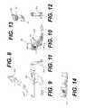
- FIG. 8is a perspective view of a right half of the housing.
- FIG. 9is a right side elevation view of the right housing half of FIG. 8 .
- FIG. 10is a left side elevation view of the right housing half of FIG. 8 .
- FIG. 11is a front elevation view of the right housing half of FIG. 8 .
- FIG. 12is a rear elevation view of the right housing half of FIG. 8 .
- FIG. 13is a cross sectional view taken along lines 13 - 13 of the right housing half of FIG. 10 .
- FIG. 14is a cross sectional view taken along lines 14 - 14 of the right housing half of FIG. 9 .
- FIG. 15is a perspective view of a left half of the housing.
- FIG. 16is a right side elevation view of the left housing half of FIG. 15 .
- FIG. 17is a left side elevation view of the left housing half of FIG. 15 .
- FIG. 18is a front elevation view of the left housing half of FIG. 15 .
- FIG. 19is a perspective view of the laser module with connected circuit board.
- FIG. 20is a plan view of the laser module.
- FIG. 21is a perspective view of a portion of the switch.
- FIG. 22is a side elevation view of the coupling.
- FIG. 23is a cross section view taken along line 23 - 23 of the coupling of FIG. 22 .
- FIG. 24is a front elevation view of the coupling of FIG. 22 .
- FIG. 25is a left side elevation view of the laser cover.
- FIG. 26is a right side elevation view of the laser cover of FIG. 25 .
- FIG. 27is a rear elevation view of the laser cover of FIG. 25 .
- FIG. 28is a bottom plan view of the laser cover of FIG. 25 .
- FIG. 29is a cross section view taken along line 29 - 29 of FIG. 26 .
- FIG. 30is a cross section view taken along line 30 - 30 of FIG. 29 .
- FIG. 31illustrates a perspective view of an exemplary firearm with a target marker according to another embodiment of the present disclosure.
- FIG. 32is a perspective view of the firearm shown in FIG. 31 .
- FIG. 33is another cross-sectional perspective view of the firearm shown in FIG. 31 .
- FIG. 34is a cross-sectional view of the firearm shown in FIG. 31 .
- the present firearm laser sight alignment assembly 20is embodied in a laser sight 22 shown operably engaged with a firearm 10 .
- the alignment assembly 20is not limited to use with handguns, but can be employed with any pistol, gun, revolver, or rifle that selectively launches a projectile, whether by compressed gas, combustion or electromagnetic actuation. Further, although the assembly 20 is shown in conjunction with a firearm that does not have any mounting rail, it is understood the assembly can be employed with laser sight 22 that engages a mounting rail. The assembly 20 is not limited by the particular laser sight or mechanism for engaging the firearm 10 .
- the firearm 10includes in relevant part a barrel 12 , a frame 14 , and a trigger guard 16 .
- the alignment assembly 20is shown as engaging the trigger guard 16 of the firearm 10 , it is understood the alignment assembly 20 can be cooperatively engaged with any portion of the firearm 10 .
- the term “longitudinal”means the dimensions along the direction of the barrel 12 .
- the term “width”means the dimension along a direction transverse to the axis of the barrel 12 .
- the term “axial”means in a direction transverse to the axis of the barrel 12 .
- the term “forward”means nearer to or towards a muzzle 13 .
- the term “rearward”means further from or away from the muzzle 13 .
- the term “below”means lower than, in the intended operating orientation of the firearm 10 .
- the term “above”means higher than, in the intended operating orientation of the firearm 10 .
- the term “preclude movement”means to prevent movement which would otherwise prevent functioning in an intended manner.
- the term “angular”means rotating about at least one of the longitudinal and axial directions.
- the alignment assembly 20includes a housing 30 , a laser module 60 , a resilient coupling 90 and a laser cover 120 .
- the housing 30retains the laser module 60 , the coupling 90 and the laser cover 120 .
- the housing 30is formed of mating halves ( 30 a , 30 b ).
- the housing 30can be formed as a single integral component or from a multitude of interconnected components. It has been found satisfactory to injection mold the housing 30 out of an elastomer such as a glass-filled nylon and particularly a nylon 6.6 compound reinforced with 33% glass fiber; suitable for processing by injection molding, wherein the material is lubricated for ease of mold release.
- the housing 30includes at least one and in some configurations, two alignment pins 32 , 34 .
- the alignment pins 32 , 34are moveable relative to the housing 30 to contact the laser module 60 .
- the alignment pins 32 , 34can be perpendicular to each other, wherein one pin provides for movement of the laser module 60 for elevation control and movement of the remaining pin provides for windage control.
- the alignment pins 32 , 34are threadingly engaged with the housing in corresponding through holes 33 , 35 .
- the through holes 33 , 35are sized so that the alignment pins cut at least a portion of corresponding threads in the housing 30 .
- the alignment pinscut the threads in the housing 30 .
- a portion of each through hole 33 , 35may be formed with threads and a remaining of the through holes is formed without threads, such that the threads are formed in the remaining portion by initial engagement of the alignment pins 32 , 34 .
- the housing 30includes a socket 42 sized to cooperatively engage a portion of the coupling 90 in an interference fit.
- the socket 42is formed in one of the halves of the housing 30 .
- the socket 42can be formed by any of a variety of constructions which provide the interference fit with the coupling 90 .
- the socket 42includes at least one, and can have two generally planar mating surfaces 44 , 46 that incline with respect to corresponding surfaces of the coupling 90 .
- the socket 42 of the housing 30has the first mating surface 44 inclined toward the muzzle 13 and the second mating surface 46 inclined away from the muzzle.
- the laser module 60includes a laser for selectively emitting a beam of radiation, such as coherent radiation, along an optical axis.
- the laser module 60includes an outer seat 64 in the form of an annular ridge.
- the outer seat 64includes a pair of contact faces 66 , 68 , wherein the faces are non-parallel.
- the outer seat 64can be arranged as a groove or recess, at least partially defined by the pair of contact faces 66 , 68 .
- the contact faces 66 , 68 of the outer seat 64 of the laser module 60can be oppositely inclined with respect to the longitudinal dimension.
- At least one of the laser module 60 and the housing 30can include a lens or window 70 through which the laser module can project, wherein the lens can function to provide a contained environment for the laser module as well as provide optical manipulation of the passing beam, such as focusing or polarization.
- the laser module 60is a commercially available assembly and is operably connected to a power supply 72 and a control board 74 shown in FIGS. 4-7 and 19 .
- a satisfactory laser 60 moduleincludes a red laser at 650 nm with an output power of 3.5 to 4.8 mW when powered by 3 volt lithium battery.
- the laser in the laser module 60can be any of a variety of lasers such as, but not limited to infrared lasers, lasers emitting at 532 nm; 635 nm or 850 nm.
- the laser module 60may comprise, for example, one or more of a green laser, a red laser, an infrared laser, an infrared light emitting diode (“LED”), a white and colored LED, a laser having an output of approximately 5 mW (it is understood that lasers having an output greater than approximately 5 mW or less than approximately 5 mW may also be used), and a short wavelength infrared laser (“SWIR”). It is understood that a SWIR may emit a signal, beam, pulse, and/or other radiation having a wavelength of between, approximately 0.9 ⁇ m and approximately 2.5 ⁇ m.
- a SWIRmay emit a signal, beam, pulse, and/or other radiation having a wavelength of between, approximately 0.9 ⁇ m and approximately 2.5 ⁇ m.
- the power supply 72can be any of a variety of commercially available batteries, either rechargeable or disposable.
- the power supply 72may be housed and/or otherwise disposed anywhere within the frame 14 and/or within the housing 30 of the alignment assembly 20 . Such a configuration is illustrate in, for example, FIGS. 4 , 5 , and 7 .
- the power supply 72may be disposed beneath or rearward of the laser module 60 .
- the power supply 72may be substantially and/or completely disposed within the frame 14 .
- the power supply 72may be disposed beneath, forward, or rearward of the control board 74 .
- control board 74is also commercially available and sold in conjunction with the laser module 60 .
- the control board 74is connected to the power supply 72 and includes a switch 76 for selectively operating or supplying the laser module 60 with power.
- the switch 76can include or be connected to an arm 78 that is accessible outside of the housing 3 .
- the switch 76is located longitudinally intermediate the muzzle 13 and the trigger guard and below the barrel 12 of the firearm 10 . Further, the switch 76 is disposed outside of the periphery of the trigger guard 16 and forward of the trigger guard.
- the switch 76can be configured such that the switch is moveable from a center, off, position to a left or a right on position. Therefore, in the center off position a portion of the switch 76 is accessible to each of the left and right sides of the housing 30 —by virtue of the construction of the housing, such as by associated depressions or recesses 31 as seen FIGS. 1-3 and the sizing of the arm 78 .
- the switch 76can therefore be actuated by the user through contact from either side of the housing 30 , thus providing non-handed actuation. That is, an outside surface of the housing 30 can include recesses, depressions or dimples 31 adjacent to the switch 76 so that the switch is moveable relative to the housing while at least initially being with the width of the housing.
- the arm 78can be sized so that the dimension of the switch transverse to the barrel 12 is no greater than the width of the firearm 10 or frame 14 .
- the arm 78being dimensioned to be within the width of the firearm 10 or frame 14 does not contact the holster and thus minimizes unintended operation of the sight 22 .
- the arm 78would have a dimension along the transverse direction of approximately 0.74 inches, or less. Therefore, in the off (centered) position of the arm 78 , the arm lies within the width of the frame 14 or the firearm 10 .
- the coupling 90cooperative engages the laser module 60 to form a laser module/coupling subassembly.
- the coupling 90includes an internal seat 92 for engaging the laser module 60 and an external seat 102 for engaging the housing 30 and the laser cover 120 .
- the internal seat 92can include facets 94 , 96 for contacting the contact faces 66 , 68 of the outer seat 64 of the laser module 60 such that an interference fit is formed between the coupling 90 and the laser module.
- interference fitmeans a fit between mating assembled surfaces (parts) that provides an interference and a deviation from nominal dimensions in at least one of the mating surfaces.
- the interference fitis sufficient to preclude relative longitudinal or axial movement between the coupling 90 and the laser module 60 (or the coupling and the housing 30 or laser cover 120 ).
- the interference fitincorporates the contact of two non-parallel generally planar surfaces, such as along a line of contact.
- the external seat 102 of the coupling 90includes at least one facet 104 for forming an interference fit with at least one of the housing 30 and the laser cover 120 .
- the external seat 102includes a pair of facets 104 , 106 for engaging the housing 30 and laser cover 120 .
- the engagement of the coupling 90 and the laser module 60is free of adhesive. That is, the interface between the components is without an outside substance that causes the parts to be held closely or firmly.
- the coupling 90can be referred to as a grommet, ring or collar extending about the laser module 60 .
- the coupling 90has a substantially uniform cross section.
- the coupling 90can include a non uniform cross section, wherein selected portions of the coupling are sized to contact the laser module 60 , the laser cover 120 and the housing 30 .
- the coupling 90can be formed to define inwardly projecting tabs or teeth, wherein the outer seat 64 of the laser module 60 includes corresponding recesses to capture the tabs, thereby retaining the coupling relative to the laser module in the desired degree of retention.
- a satisfactory material of the coupling 90provides for a resilient but deformable shape.
- An available material for the coupling 90is Santoprene®, a thermoplastic vulcanizate (TPV) sold by Exxon Mobile. The TPV is believed to be a mixture of in-situ cross linking of EPDM rubber and polypropylene. Santoprene® 101-64 with a 69 durometer has been found satisfactory for the coupling 90 .
- the laser cover 120contacts the coupling 90 as the coupling is engaged with the laser module 60 to retain the laser module relative to the housing 30 .
- the laser cover 120is shown as a separate component than the housing halves 30 , it is understood the structure and function of the laser cover can be accomplished by a structured housing half or other component for engaging the housing.
- the laser cover 120includes a socket 122 sized to cooperatively engage a portion of the coupling 90 in an interference fit.
- the socket 122is formed in laser cover 120 to engage the external seat 102 of the coupling 90 in an interference fit.
- the socket 122includes at least one, and in selected configurations two inclined surfaces 124 , 126 for contacting the facets 104 , 106 of the coupling 90 in the interference fit, as shown in FIGS. 3B and 3C .
- the laser cover 120further includes a capture recess 138 for retaining a bias member 140 , such as a coil spring, to contact the laser module 60 .
- a bias member 140such as a coil spring
- the engagement of the coupling 90 and the laser cover 120is free of adhesive.
- the laser cover 120 and the housing 30include corresponding apertures and the housing includes threaded (or threadable) recesses for cooperatively engaging the laser cover and the housing.
- threaded connectionis shown in the Figures, it is understood any available mechanical fastening could be employed, such as snap fit, press fit or friction fit.
- connection of the laser cover 120 to the housing 30is defined by contacting stop surfaces on the housing and the laser cover 36 , 136 , respectively. That is, the laser cover 120 and the housing 30 are engaged, such as threaded together, to retain the laser module/coupling subassembly until the stop surfaces contact 36 , 136 . Thus, any deviation from nominal in the laser module/coupling subassembly does not vary the engagement of the laser cover 120 and the housing 30 .
- the sockets 42 , 122 of the housing 30 and the laser cover 120are configured, such that upon engagement of the laser cover and the housing to retain the laser module/coupling subassembly, the laser module 60 is disposed in a predetermined nonaligned orientation. That is, the laser module 60 is initially aligned in a predetermined orientation that is not an intended operating orientation. For example, if the laser module were operated upon initial engagement between the housing 30 and the laser cover 120 , the projected beam would always be in the same quadrant relative to the longitudinal axis.
- the remaining half 30 b of the housing 30is then connected to encapsulate the laser module 60 , the coupling 90 and the laser cover 120 .
- the coupling 90is connected to the laser module 60 by virtue of the interference fit between the outer seat 64 of the laser module 60 and the internal seat 92 of the coupling 90 .
- the connection of the coupling 90 and the laser module 60is operably achieved without requiring or employing any adhesives.
- the coupling 90is then located within the socket 42 of the housing 30 , and the laser cover 120 is engaged with the housing to dispose the coupling within the socket 122 of the laser cover 120 .
- the laser module 60is thus disposed in the predetermined non aligned orientation with respect to a nominal aligned position.
- the laser module 60can then be readily brought to a nominal alignment position by moving the alignment pins 32 , 34 in a known direction (as the non alignment position is known). Further, as the non aligned position is known, the amount of movement of the respective alignment pin 32 , 34 is generally known, and thus adjustment to the nominal alignment is readily accomplished. It is understood that there may be a de minimis amount of translation of the laser module 60 along the longitudinal or axial direction relative to the coupling 90 , the housing 30 or the laser cover 120 during angular movement of the laser module. However, any such translation is merely a residual effect of the angular movement (rotation) of the laser module about at least one of longitudinal or axial directions.
- the laser module 60pivots about a point that is within the dimension of the coupling 90 as the coupling extends along the longitudinal direction. In a further configuration, the laser module 60 pivots about a point that is within the volume defined by the coupling 90 (the volume including a volume of a through hole in the coupling for receiving the laser module.
- the resiliency of the coupling 90allows the laser module 60 to be moved angularly with respect to the housing 30 and laser cover 120 , without requiring longitudinal or axial movement. Further, as the interference fits are without adhesives and the engagement of the laser cover and housing is set by the stop surfaces, the movement of the laser module 60 by the alignment pins 32 , 34 is limited to angular movement and does not result in misaligning axial or longitudinal movement.
- the housing 30is then engaged with the firearm 10 , and depending on the desired sighting in of the user, the laser module 60 can be further aligned by the alignment pins 32 , 34 .
- the bias of the spring 140 and the coupling 90 along with the alignment pins 32 , 34act on the laser module 60 and tend to retain the laser module in a given position.
- a driversuch as an Allen wrench or a screw driver.
- the alignment pins 32 , 34can change the angular position the laser module 60 relative to the housing 30 and hence firearm 10 to provide the desired alignment position, such as the laser beam coinciding with a point of impact of a projectile fired from the firearm at a desired or predetermined distance.
- the second housing halfcould engage the first housing half and form the recited interference fits and position the laser module 60 in the predetermined non aligned position.
- the frame of firearm 10may comprise a grip 141 .
- the bottom of the grip 141may include a magazine well 142 , which may have a magazine 144 inserted into it.
- the magazine 144may include a number of rounds of ammunition (not shown) and/or other like projectiles disposed therein.
- the firearm 10may include a trigger 146 which, when depressed properly, may cause the firearm 10 to discharge a projectile from the magazine 144 via a firing process known in the art.
- the barrel 12may be housed within a slide 148 . When the projectile is discharged from the firearm 10 , the projectile may exit the firearm 10 along a firing axis 150 via the muzzle end 152 of the barrel 12 .
- the firing axis 150may be substantially parallel to the barrel 12 of the firearm 10 and, further, may be longitudinal.
- the barrel 12may be selectively removable from the frame 14 . Further, the barrel 12 may be held in place by the slide 148 , such that when the slide 148 is removed, the barrel 12 may also be removed.
- the barrel 12may be otherwise rigidly connected and removable from the frame 14 .
- the laser module 60may be disposed within a chamber 200 ( FIG. 32 ) formed by the frame 10 beneath the barrel 12 of the firearm 10 .
- the laser module 60may be configured to emit a beam of radiation along a beam path 156 , which may exit the frame 14 of the firearm 10 through an opening 158 in the muzzle end 152 of the frame 14 .
- the housing 30 and/or other components of the alignment assembly 20 described abovemay be omitted. Wherever possible, like item numbers have been used to identify like components of the embodiment shown in FIGS. 31-34 .
- one or more optical componentsmay be disposed optically downstream of the laser module 60 along and/or within the beam path 156 .
- the optical componentmay be configured to collimate radiation emitted by the laser module 60 and/or otherwise condition a beam emitted from the laser module 60 extending along the beam path 156 .
- the optical componentmay include any of a variety of lenses, such as the lens or window 70 described above, zoom components, magnification components, domes, diffraction gratings, filters, prisms, mirrors, and/or other like optical components, mechanical components, or combinations thereof.
- one or more beams of radiation emitted by the laser module 60may pass through, be shaped by, be conditioned by, and/or otherwise optically interact with the optical component before exiting the firearm 10 .
- the chamber 200may be formed by and/or included within a substantially hollow portion of the muzzle 13 (i.e., a “muzzle portion”) beneath the barrel 12 ( FIG. 31 ) of the firearm 10 .
- the chamber 200may be disposed between a first outer wall 202 of the frame 14 , and a second outer wall 204 opposite the first outer wall 202 .
- the laser module 60may be disposed within the chamber 200 .
- the first outer wall 202may include a first surface 206 , and a second surface 208 ( FIG. 34 ) opposite the first surface 206 .
- a first passage 210may be disposed within the first outer wall 202 .
- the passage 210may include a first opening on the first surface 206 , and a second opening opposite the first opening on the second surface 208 of the outer wall 202 .
- the passage 210may extend substantially in the axial direction and, in further embodiments, the passage 210 may be a tapped hole.
- the passage 210may be substantially cylindrically-shaped and may be configured with a series of threads.
- a second passage 212may be included within the first outer wall 202 .
- the first surface 206may include a first opening of the passage 212
- the second surface 208may include a second opening of the passage 212 opposite the first opening.
- the passage 212may be substantially cylindrical, substantially square, and/or any other known shape.
- the passage 212may be configured to accept a switch and/or a switch arm (not shown). Such a switch and/or switch arm may be the substantially similar to the switch 76 and arm 78 described above.
- a portion of such a switch and/or switch armmay be disposed within the chamber 200 for selectively activating the laser module 60 by forming an electrical connection between the laser module 60 and the power supply 72 .
- the switch, power supply 72 , and/or laser module 60may be operably connected to the control board 74 described above with respect to FIGS. 4-7 and 19 .
- the switch 76may comprise multiple positions such that the switch 76 may create a closed and/or open circuit either enabling or disabling the flow of power between the laser module 60 and the power supply 72 . For example, when the switch 76 is in a closed position, the switch 76 may create a closed electrical circuit which may selectively power the laser module 60 .
- the switch 76may also include an open position such that the switch 76 creates an open circuit which may prevent electricity from flowing to the laser module 60 .
- the switch 76may comprise any tap-on/tap-off switch known in the art.
- the switch 76may be configured to direct a signal to a microprocessor or other like control component associated with the control board 74 directing the control component to activate or deactivate the laser module 60 .
- the switch 76may be accessible by the user on both sides of the firearm 10 .
- the switch 76may be accessible via both the first and second outer walls 202 , 204 .
- a first switch 76may be disposed on a first side of the control board 74 and a second switch 76 may be disposed on a second side of the control board 74 opposite the first side thereof.
- the first switch 76may be accessible via the first outer wall 202 and the second switch 76 may be accessible via the second outer wall 204 .
- Such switches 76may be interrelated and may both be connected to the control component of the control board 74 for activation/deactivation of the laser module 60 .
- switches 76may also be used in the exemplary embodiments described above with respect to FIGS. 1-30 .
- the switch 76may not be disposed within the chamber 200 .
- the switch 76may be disposed on and/or otherwise attached to the frame 14 of the firearm 10 .
- the second wall 204may include an additional passage (not shown) opposite the passage 212 .
- the additional passagemay have an opening disposed on a first side of the second wall 204 , and a second opening opposite the first opening, on a second side of the second wall 204 .
- the additional passagemay be substantially opposite the passage 212 and may be configured to accept a portion of the switch 76 such that the switch 76 may be operable from either side of the firearm 10 .
- Such passagesmay be included in both the first and second outer walls 202 , 204 and, in exemplary embodiments, such passages may facilitate usage of a tap-on/tap-off switch 76 .
- one or both of the resilient coupling 90 and the laser cover 120may be disposed at least partially within the chamber 200 of the firearm 10 .
- the resilient coupling 90may facilitate angular movement of the laser module 60 within the chamber 200 and relative to, for example, the frame 14 , without requiring longitudinal or axial movement. Such movement may be substantially similar to the movement of laser module 60 described above with respect to the exemplary embodiments of FIGS. 1-30 .
- the cover 120 and/or the frame 14may be configured to accept the outer diameter geometry of the resilient coupling 90 .
- the frame 14may include a first groove 316 which may have a shape complimentary to the outer surface of the resilient coupling 90 .
- the first groove 316may be configured to cooperate and/or form an interference fit with the facets 104 , 106 of the external seat 102 .
- the cover 120may contain a corresponding second groove 318 which may also be configured to accept the outer surface of the resilient coupling 90 .
- the first and second grooves 316 , 318may be disposed substantially opposite each other when the cover 120 is assembled within the chamber 200 .
- the resilient coupling 90 and the grooves 316 , 318may form a connection, such as an adhesive-free interference fit, and/or other similar connection.
- such engagement between the resilient coupling 90 and the grooves 316 , 318may allow for angular movement (rotation) of the laser module 60 about at least one of the longitudinal or axial directions described above.
- the laser module 60may be disposed between at least one alignment pin 34 , the cover 120 , and the frame 14 . In further embodiments, the laser module 60 may further be disposed between a pair of alignment pins 32 , 34 , the cover 120 , and the frame 14 .
- the alignment pins 32 , 34may be disposed within respective passages 210 , 322 formed in the frame 14 of the firearm 10 .
- the passages 210 , 322may each extend in an axial direction transverse to the axis of the barrel 12 . In such embodiments, the passages 210 , 322 may be spaced approximately 90 degrees from one another.
- the passages 210 , 332may comprise tapped thru holes configured with a series of threads similar to the through holes 33 , 35 described above with respect to the housing 30 .
- the alignment pins 32 , 34may comprise flat or Phillips-head screws, set screws, bolts, dowels, clips, clamps and/or any other known type of fasteners.
- the alignment pins 32 , 34may be configured with a series of threads that may mate with a series of threads of the respective passages 210 , 322 , such that the alignment pins 32 , 34 are threadingly engaged with the frame 14 via the passages 210 , 322 .
- the alignment pins 23 , 34may be movable in relation to the frame 14 .
- the alignment pin 34may be configured to translate along an axis 324 extending in the axial direction. Rotation of the alignment pin 34 around the axis 324 may cause the alignment pin 34 to move in a direction L and/or a direction P ( FIG. 34 ) relative to the frame 14 .
- rotation of the alignment pin 34 around the axis 324 in a clockwise directionmay move the alignment pin 34 in the L direction and rotation in a counter-clockwise direction may move the alignment pin 34 in the P direction, or vice versa.
- the alignment pin 32may be configured to translate along an axis 402 extending in the axial direction substantially perpendicular to axis 324 . Rotation of the alignment pin 32 around the axis 402 may cause the alignment pin 32 to move in a direction M and/or a direction N ( FIG. 34 ) relative to the frame 14 . For example, rotation of the alignment pin 32 around the axis 402 in a clockwise direction may move the alignment pin 32 in the N direction and rotation in a counter-clockwise direction may move the alignment pin 32 in the M direction, or vice versa.
- the alignment pins 32 , 34may be configured to contact an outer surface 321 of the laser module 60 at respective locations forward or rearward of the outer seat 64 .
- a first end of the alignment pin 34may be disposed within the passage 322 , and a second end of the alignment pin 34 may contact the outer surface 321 of the laser module 60 .
- the outer surface 321 of the laser module 60may contain one or more features (not shown) configured to accept the respective alignment pins 32 , 34 .
- the outer surface 321 of the laser module 60may contain one or more grooves, notches, or indents configured to assist with alignment of the laser module 60 .
- the respective second ends of the alignment pins 32 , 34may mate with the respective indents while aligning the laser module 60 . It is understood, however, that when the cover 120 has been properly installed within the chamber 200 such that the laser module 60 is disposed within the chamber 200 between the cover 120 and the frame 14 , and the cover 120 may form an interference fit with the resilient coupling 90 to hold the laser module 60 stationary within the chamber 200 . In such a configuration, the alignment pins 32 , 34 may contact the outer surface 321 while the cover 120 is spaced from the outer surface 321 by the resilient coupling 90 . Such spacing may allow for alignment of the laser module 60 relative to the frame 14 and the cover 120 by the alignment pins 32 , 34 .
- the laser module 60may be further disposed between a biasing device 404 and the alignment pins 32 , 34 .
- the biasing device 404may comprise any compressible component known in the art such as a spring, a flexible compressible rod, and/or other known biasing device.
- the biasing device 404may be disposed within a pocket 406 formed by the cover 120 and/or the frame 14 of the firearm 10 .
- the frame 14 of the firearm 10may form a bottom portion of the pocket 406 and the cover 120 may form a top portion of the pocket 406 .
- the pocket 406may be substantially cylindrically-shaped.
- the frame 14may contain a semi-cylindrical cutout which may have a substantially similar diameter to a complimentary semi-cylindrical cutout in the cover 120 .
- the two semi-cylindrical cutoutsmay form the pocket 406 which may have a resulting substantially cylindrical shape.
- the pocket 406may be any other shape, for example, the pocket 406 may be substantially square, substantially rectangular, and/or any other shape configured to accept the biasing device 404 .
- the biasing device 404may be disposed between an end surface 410 of the pocket 406 and the laser module 60 .
- the biasing device 404when compressed the biasing device 404 may exert a force, such as a biasing force, on the laser module 60 and the end surface 410 .
- a first end of the biasing device 404may contact the laser module 60
- a second end opposite the first endmay contact the end surface 410 of the pocket 406 .
- the biasing forcemay be in direction S and/or direction R, which may be between approximately 130 degrees and approximately 150 degrees from the axis 402 and/or the axis 324 . It is understood that in further exemplary embodiments, the biasing force may be directed at other orientations relative to one or more of the axes 402 , 324 .
- the laser module 60may be further disposed between a second biasing device (not shown).
- the first biasing device 404may be substantially opposite the alignment pin 34 such that a center axis of the pocket 406 may be parallel to and align with the axis 324 of the alignment pin 34 .
- the first biasing device 404may be disposed within a pocket formed by the cover 120 and/or the frame 14 . In such a configuration, the first biasing device 404 may exert a biasing force on the laser module 60 in the L and/or P direction.
- the second biasing deviceon the other hand, may be located substantially opposite the second alignment pin 32 and may be disposed within a second pocket (not shown).
- the second pocketmay be formed by the cover 120 and/or the frame 14 .
- the frame 10may contain a first semi-cylindrical cutout and the cover 120 may contain a second semi-cylindrical cutout with a diameter substantially similar to the first cutout such that when the cover 120 is fixed to the frame 14 , the two cutouts form a substantially cylindrical pocket.
- the second pocketmay have a center axis which may align with the axis 402 of the second alignment pin 32 .
- the second biasing devicemay exert a biasing force on the laser module 60 in the M and/or N direction.
- the one or more biasing devices described hereinmay assist in biasing the laser module 60 in a predetermined orientation that is not an intended operating orientation.
- the one or more biasing devices, chamber 200 , and cover 120may be configured such that upon engagement of the cover 120 and the frame 14 to retain the laser module 60 within the chamber 200 , the laser module 60 may be disposed in a predetermined nonaligned orientation.
- the one or more biasing devicesmay bias the laser module 60 toward each alignment pin 32 , 34 by between approximately 1 degree and approximately 5 degrees relative to the beam path 156 .
- the communication between, for example, the cover 120 and the resilient coupling 90may also bias the laser module 60 in the direction of one or both of the alignment pins 32 , 34 .
- the trajectory of the beam path 156may intersect with the trajectory of the firing axis 150 at a point of impact disposed a predetermined distance from the firearm 10 .
- the beam path 156may comprise an optical axis highlighting a point of impact on a target located a set distance from the firearm 10 .
- accurately aligning the beam path 156 and the firing axis 150may require relative movement of the laser module 60 to the firearm 10 .
- the laser module 60may be movable in the L and/or P direction.
- the alignment pin 34may be configured to move the laser module 60 in relation to the frame 14 of the firearm 10 .
- rotation of the alignment pin 34 around the axis 324may pivot, rotate, and/or otherwise move the laser module 60 in relation to the frame 14 .
- Rotation of the alignment pin 34may cause the laser module 60 to pivot, rotate, and/or otherwise move in a direction substantially transverse to the firing axis 150 ( FIG. 31 ) in the L and/or P direction.
- the biasing device 404may be configured to exert a biasing force in the R direction against the outer surface 321 of the laser module 60 and may further facilitate movement of the laser module 60 .
- movement of the alignment pin 34 in the P directionmay cause the biasing device 404 to expand and pivot, rotate, and/or otherwise move the laser module 60 substantially in the P and/or R direction.
- movement of the alignment pin 34 in the L directionmay compress the biasing device 404 and may pivot, rotate, and/or otherwise move the laser module 60 in the substantially in the L and/or S direction.
- Movement of the laser module 60 in the L, P, S, R, M, N, and/or any other direction facilitated by movement of one or both of the alignment pins 32 , 34 and biasing device 404may assist in aligning the beam path 156 with the firing axis 150 of the firearm 10 .
- the laser module 60may be further pivotable, rotateable, and/or otherwise moveable in the M and/or N direction substantially transverse to the firing axis 150 .
- rotation of the alignment pin 32 about the axis 402may move the alignment pin 32 in the M and/or N direction, which may, through contact with the laser module 60 , also pivot, rotate, and/or otherwise move the laser module 60 in the M and/or N direction.
- movement of the alignment pin 32 in the M directionmay cause the biasing device 404 to exert a positive bias on the laser module 60 in the R direction such that movement of the alignment pin 32 in the M direction may enable the biasing device 404 to pivot, rotate, and/or otherwise move the laser module 60 substantially in the R and/or M direction.
- movement of the alignment pin 32 in the N directionmay pivot, rotate, and/or otherwise move the laser module 60 in the same direction and may cause the biasing device 404 to compress.
- such angular movement of the laser module 60may cause the beam path 156 to align with the firing axis 150 at a predetermined distance from the firearm 10 .
Landscapes
- Engineering & Computer Science (AREA)
- General Engineering & Computer Science (AREA)
- Physics & Mathematics (AREA)
- Optics & Photonics (AREA)
- Aiming, Guidance, Guns With A Light Source, Armor, Camouflage, And Targets (AREA)
- Lasers (AREA)
- Semiconductor Lasers (AREA)
Abstract
Description
Claims (26)
Priority Applications (5)
| Application Number | Priority Date | Filing Date | Title |
|---|---|---|---|
| US13/759,768US8713844B2 (en) | 2011-09-26 | 2013-02-05 | Firearm laser sight alignment assembly |
| US14/269,892US9879945B2 (en) | 2011-09-26 | 2014-05-05 | Firearm laser sight alignment assembly |
| US15/882,444US10718593B2 (en) | 2011-09-26 | 2018-01-29 | Firearm laser sight alignment assembly |
| US16/932,061US11965710B2 (en) | 2011-09-26 | 2020-07-17 | Firearm laser sight alignment assembly |
| US18/642,671US12422221B2 (en) | 2011-09-26 | 2024-04-22 | Firearm laser sight alignment assembly |
Applications Claiming Priority (2)
| Application Number | Priority Date | Filing Date | Title |
|---|---|---|---|
| US13/245,309US8683731B2 (en) | 2011-09-26 | 2011-09-26 | Firearm laser sight alignment assembly |
| US13/759,768US8713844B2 (en) | 2011-09-26 | 2013-02-05 | Firearm laser sight alignment assembly |
Related Parent Applications (1)
| Application Number | Title | Priority Date | Filing Date |
|---|---|---|---|
| US13/245,309Continuation-In-PartUS8683731B2 (en) | 2011-09-26 | 2011-09-26 | Firearm laser sight alignment assembly |
Related Child Applications (1)
| Application Number | Title | Priority Date | Filing Date |
|---|---|---|---|
| US14/269,892ContinuationUS9879945B2 (en) | 2011-09-26 | 2014-05-05 | Firearm laser sight alignment assembly |
Publications (2)
| Publication Number | Publication Date |
|---|---|
| US20130145672A1 US20130145672A1 (en) | 2013-06-13 |
| US8713844B2true US8713844B2 (en) | 2014-05-06 |
Family
ID=48570729
Family Applications (5)
| Application Number | Title | Priority Date | Filing Date |
|---|---|---|---|
| US13/759,768ActiveUS8713844B2 (en) | 2011-09-26 | 2013-02-05 | Firearm laser sight alignment assembly |
| US14/269,892Active2033-04-28US9879945B2 (en) | 2011-09-26 | 2014-05-05 | Firearm laser sight alignment assembly |
| US15/882,444ActiveUS10718593B2 (en) | 2011-09-26 | 2018-01-29 | Firearm laser sight alignment assembly |
| US16/932,061Active2032-07-06US11965710B2 (en) | 2011-09-26 | 2020-07-17 | Firearm laser sight alignment assembly |
| US18/642,671ActiveUS12422221B2 (en) | 2011-09-26 | 2024-04-22 | Firearm laser sight alignment assembly |
Family Applications After (4)
| Application Number | Title | Priority Date | Filing Date |
|---|---|---|---|
| US14/269,892Active2033-04-28US9879945B2 (en) | 2011-09-26 | 2014-05-05 | Firearm laser sight alignment assembly |
| US15/882,444ActiveUS10718593B2 (en) | 2011-09-26 | 2018-01-29 | Firearm laser sight alignment assembly |
| US16/932,061Active2032-07-06US11965710B2 (en) | 2011-09-26 | 2020-07-17 | Firearm laser sight alignment assembly |
| US18/642,671ActiveUS12422221B2 (en) | 2011-09-26 | 2024-04-22 | Firearm laser sight alignment assembly |
Country Status (1)
| Country | Link |
|---|---|
| US (5) | US8713844B2 (en) |
Cited By (29)
| Publication number | Priority date | Publication date | Assignee | Title |
|---|---|---|---|---|
| USD741391S1 (en)* | 2014-08-21 | 2015-10-20 | Field Sport Inc. | Compact video camera for pistol |
| USD747757S1 (en)* | 2014-09-12 | 2016-01-19 | Isaac S. Daniel | Camera recording device for use with a gun |
| US9772163B2 (en) | 2015-01-15 | 2017-09-26 | Streamlight, Inc. | Modular light mountable on a handgun |
| US20180010880A1 (en)* | 2013-11-13 | 2018-01-11 | Recover, Llc | Integrated Handgun Grip and Rail |
| US20180094900A1 (en)* | 2016-10-03 | 2018-04-05 | Streamlight, Inc. | Modular light mountable on a handgun |
| US10344959B2 (en) | 2017-11-20 | 2019-07-09 | Streamlight, Inc. | Portable and/or mountable light |
| USD857268S1 (en) | 2017-10-24 | 2019-08-20 | Streamlight, Inc. | Mountable light |
| USD857960S1 (en) | 2017-10-24 | 2019-08-27 | Streamlight, Inc. | Mountable light |
| USD898260S1 (en) | 2019-05-24 | 2020-10-06 | Streamlight, Inc. | Mountable light |
| USD898261S1 (en) | 2019-05-24 | 2020-10-06 | Streamlight, Inc. | Mountable light |
| USD907268S1 (en) | 2019-07-23 | 2021-01-05 | Streamlight, Inc. | Mountable light |
| USD907270S1 (en) | 2019-07-23 | 2021-01-05 | Streamlight, Inc. | Mountable light |
| USD907269S1 (en) | 2019-07-23 | 2021-01-05 | Streamlight, Inc. | Mountable light |
| USD907267S1 (en) | 2019-07-23 | 2021-01-05 | Streamlight, Inc. | Mountable light |
| US10962314B2 (en) | 2017-04-12 | 2021-03-30 | Laser Aiming Systems Corporation | Firearm including electronic components to enhance user experience |
| USD919149S1 (en) | 2019-07-23 | 2021-05-11 | Streamlight, Inc. | Mountable light |
| US11506366B2 (en) | 2020-08-07 | 2022-11-22 | Streamlight, Inc. | Mountable light having interchangeable clamping elements |
| USD997285S1 (en) | 2020-08-07 | 2023-08-29 | Streamlight, Inc. | Mountable light |
| USD997413S1 (en) | 2020-08-07 | 2023-08-29 | Streamlight, Inc. | Mountable light |
| USD999332S1 (en) | 2018-10-09 | 2023-09-19 | Streamlight, Inc. | Rail mountable gun light with rotationally keyed mount assembly |
| USD999624S1 (en) | 2020-08-07 | 2023-09-26 | Streamlight, Inc. | Clamping members |
| USD1005541S1 (en) | 2019-07-23 | 2023-11-21 | Streamlight, Inc. | Mountable light |
| US12130121B1 (en) | 2020-07-21 | 2024-10-29 | Laser Aiming Systems Corporation | Data redundancy and hardware tracking system for gun-mounted recording device |
| US12173992B1 (en) | 2020-07-21 | 2024-12-24 | Laser Aiming Systems Corporation | Gun mounted recording device with quick release battery |
| USD1061979S1 (en) | 2021-01-07 | 2025-02-11 | Streamlight, Inc. | Mountable light |
| USD1091907S1 (en) | 2021-01-07 | 2025-09-02 | Streamlight, Inc. | Mountable light |
| USD1092809S1 (en) | 2021-01-07 | 2025-09-09 | Streamlight, Inc. | Mountable light |
| US12422221B2 (en) | 2011-09-26 | 2025-09-23 | Crosman Corporation | Firearm laser sight alignment assembly |
| US12431737B2 (en) | 2016-10-14 | 2025-09-30 | Laser Aiming Systems Corporation | Gun-mounted recording device |
Families Citing this family (27)
| Publication number | Priority date | Publication date | Assignee | Title |
|---|---|---|---|---|
| US8683731B2 (en) | 2011-09-26 | 2014-04-01 | Lasermax, Inc. | Firearm laser sight alignment assembly |
| PL3019812T3 (en) | 2013-07-09 | 2019-04-30 | Zieger Cory | Modular holographic sighting system |
| US9500442B2 (en) | 2013-07-15 | 2016-11-22 | OptiFlow, Inc. | Holographic gun sight |
| WO2015105677A1 (en)* | 2014-01-07 | 2015-07-16 | Ochoco Arms | Laser adjustment slide system |
| US10809037B2 (en)* | 2015-01-09 | 2020-10-20 | Hogue, Inc. | Firearm handgrip assembly with laser gunsight system |
| USD796622S1 (en) | 2015-01-15 | 2017-09-05 | Streamlight, Inc. | Light mountable on a handgun |
| US10247515B2 (en) | 2015-06-26 | 2019-04-02 | Ziel Optics, Inc. | Holographic sight with optimized reflection and image angles |
| US10254532B2 (en) | 2015-06-26 | 2019-04-09 | Ziel Optics, Inc. | Hybrid holographic sight |
| US10161705B2 (en)* | 2015-12-04 | 2018-12-25 | Shane Keng | Magazine floorplate with one or more retaining clips for a firearm |
| US10024629B2 (en)* | 2016-01-18 | 2018-07-17 | Sig Sauer, Inc. | Accessory mounting system |
| USD802704S1 (en)* | 2016-07-28 | 2017-11-14 | Crimson Trace Corporation | Laser device |
| USD812180S1 (en)* | 2016-07-28 | 2018-03-06 | Crimson Trace Corporation | Laser device |
| USD812179S1 (en)* | 2016-07-28 | 2018-03-06 | Crimson Trace Corporation | Laser device |
| USD812707S1 (en)* | 2016-07-28 | 2018-03-13 | Crimson Trace Corporation | Laser device |
| USD812182S1 (en)* | 2016-08-02 | 2018-03-06 | Crimson Trace Corporation | Laser device |
| US10222171B2 (en)* | 2016-12-01 | 2019-03-05 | Bushnell Inc. | Forward grip laser (FGL) |
| USD837928S1 (en)* | 2017-01-13 | 2019-01-08 | Crimson Trace Corporation | Laser device |
| USD837332S1 (en)* | 2017-01-13 | 2019-01-01 | Crimson Trace Corporation | Laser device |
| USD860375S1 (en) | 2017-10-06 | 2019-09-17 | Bushnell Inc. | Forward grip laser sight |
| USD915541S1 (en) | 2017-10-06 | 2021-04-06 | Vista Outdoor Operations Llc | Forward grip laser sight |
| US10704859B2 (en)* | 2018-11-06 | 2020-07-07 | Gi Sportz Direct Llc | Compressed gas gun front grip having battery access panel |
| USD961714S1 (en) | 2019-11-21 | 2022-08-23 | Eotech, Llc | Weapon sight |
| US11486675B2 (en) | 2019-11-21 | 2022-11-01 | Eotech, Llc | Weapon sight with tapered housing |
| US12235075B1 (en) | 2020-09-02 | 2025-02-25 | Laser Aiming Systems Corporation | Firearm accessory device |
| USD1035813S1 (en) | 2020-09-02 | 2024-07-16 | Laser Aiming Systems Corporation | Laser finger stop |
| US11808546B2 (en)* | 2021-01-18 | 2023-11-07 | Trajectory, LLC | Aiming apparatus for a firearm |
| US12196526B2 (en) | 2021-06-02 | 2025-01-14 | Multitasker Tools Llc | Tool and pistol magazine base plate |
Citations (45)
| Publication number | Priority date | Publication date | Assignee | Title |
|---|---|---|---|---|
| US4916713A (en)* | 1988-01-26 | 1990-04-10 | Peter Gerber | Laser or light target designator device |
| US5056254A (en)* | 1990-10-09 | 1991-10-15 | Bechtel Daniel L | Method and apparatus for attaching an auxiliary aiming device to a semi-automatic pistol |
| US5179235A (en)* | 1991-09-10 | 1993-01-12 | Toole Ronald L | Pistol sighting device |
| US5253443A (en) | 1990-06-06 | 1993-10-19 | Michel Baikrich | Laser-beam aiming device |
| US5282594A (en)* | 1993-05-20 | 1994-02-01 | Huang Chao C | Laser sight mounting device |
| US5375362A (en)* | 1993-10-07 | 1994-12-27 | Sturm, Ruger & Company, Inc. | Laser sighted firearm |
| US5485695A (en)* | 1993-09-21 | 1996-01-23 | Glock; Gaston | Laser aiming device |
| US5531040A (en)* | 1993-01-14 | 1996-07-02 | Tac Star Industries, Inc. | Laser module mounting means for weapons and other applications |
| US5581898A (en) | 1993-07-30 | 1996-12-10 | Laser Devices, Inc. | Modular sighting laser for a firearm |
| US5590486A (en)* | 1994-12-27 | 1997-01-07 | Tac Star Industries, Inc. | Externally mountable laser sight for weapons and other applications |
| US5621999A (en)* | 1994-12-27 | 1997-04-22 | Tac Star Industries, Inc. | Externally mountable laser sight with slide switch |
| US5706600A (en)* | 1994-07-08 | 1998-01-13 | Crimson Trace Corporation | Laser sighting device for a weapon |
| US5758448A (en)* | 1997-01-02 | 1998-06-02 | Laser Devices, Inc. | Laser system mounting device |
| US5784823A (en) | 1997-04-18 | 1998-07-28 | Quarton Inc. | Laser sight assembly |
| US6230431B1 (en)* | 1999-07-07 | 2001-05-15 | Limate Corporation | Night laser sight |
| US6393752B1 (en)* | 1999-10-04 | 2002-05-28 | Keith P. Oliver | Mounting device of pistol laser site |
| US20020100202A1 (en)* | 2001-02-01 | 2002-08-01 | Paul Lin | Sliding sheath type fixture for pistol accessory |
| US20040128900A1 (en)* | 2003-01-03 | 2004-07-08 | Chen Tony K.T. | Connecting device for weapon accessory |
| US20050257415A1 (en)* | 1998-07-02 | 2005-11-24 | Solinsky Kenneth S | Auxiliary device for a weapon and attachment thereof |
| US7117627B2 (en)* | 2004-06-02 | 2006-10-10 | Tactical And Rescue Equipment, Llc | Mounting assembly and methods of using same |
| US20070113462A1 (en)* | 2005-11-23 | 2007-05-24 | Shu-Li Ho | Structure for fixing a gun scope |
| US20070193103A1 (en)* | 2006-01-20 | 2007-08-23 | Daniel Cheng | Gun system and accessory thereof |
| US7331137B2 (en) | 2003-07-03 | 2008-02-19 | Yao-Hsi Hsu | Laser pointer as auxiliary sight of firearm |
| US7395627B2 (en)* | 2006-03-29 | 2008-07-08 | Surefire, Llc | Accessory mount for a firearm |
| US7472830B2 (en) | 2005-01-25 | 2009-01-06 | Crimson Trace Corporation | Compact laser aiming assembly for a firearm |
| USD603478S1 (en) | 2008-09-30 | 2009-11-03 | Crimson Trace Corporation | Laser gunsight system for a firearm trigger guard |
| US20090307955A1 (en)* | 2007-06-18 | 2009-12-17 | Nudyke Richard | Switch for the control of weapon mounted electronic assemblies, a weapon having a control switch and a method for using weapon |
| US20100064568A1 (en)* | 2007-06-18 | 2010-03-18 | Nudyke Richard | Switch for the control of weapon mounted electronic assemblies, a weapon having a control switch and a method for using a weapon |
| US7726061B1 (en)* | 2004-03-13 | 2010-06-01 | Laser Devices, Inc. | Dual beam laser module |
| US20100154279A1 (en)* | 2008-12-23 | 2010-06-24 | Para Usa, Inc. | Firearm |
| US20100162610A1 (en)* | 2008-10-10 | 2010-07-01 | Moore Larry E | Side-mounted lighting device |
| US20110035984A1 (en)* | 2008-10-01 | 2011-02-17 | Ming-Yen Liu | Wireless Camera Device for a Gun |
| US20110047851A1 (en)* | 2007-12-14 | 2011-03-03 | Lasermax, Inc. | Removable foregrip with laser sight |
| US20110061283A1 (en)* | 2009-09-11 | 2011-03-17 | NiteScout LLC | Attachment system used to mount accessory devices to a firearm |
| USD636049S1 (en) | 2010-03-25 | 2011-04-12 | Crimson Trace Corporation | Laser gunsight system for a firearm |
| US7926218B2 (en) | 2007-01-17 | 2011-04-19 | Surefire, Llc | Laser aiming apparatus using a rocker |
| USD636837S1 (en) | 2010-03-25 | 2011-04-26 | Crimson Trace Corporation | Laser gunsight system for a firearm |
| US20110107648A1 (en)* | 2004-05-21 | 2011-05-12 | Michael Tuz | Pistol concealment device |
| US20110167707A1 (en)* | 2008-03-11 | 2011-07-14 | Gross Barbara R | Tactical illuminator |
| US20110232151A1 (en)* | 2010-03-29 | 2011-09-29 | Smith & Wesson Corp. | Integral, frame-mounted laser aiming device |
| US8109024B2 (en)* | 2008-10-19 | 2012-02-07 | Terrill Abst | Trigger activated switch |
| US20120047787A1 (en)* | 2010-08-30 | 2012-03-01 | Smith & Wesson Corp. | Frame-mounted laser aiming device |
| US20120085015A1 (en)* | 2010-10-07 | 2012-04-12 | Ho-Sheng Wei | Toy gun having a laser sight |
| US20120144718A1 (en)* | 2008-09-30 | 2012-06-14 | Crimson Trace Corporation | Laser gunsight system for a firearm trigger guard |
| US20120198748A1 (en)* | 2011-02-07 | 2012-08-09 | Ignacio Vicente Ospino Orozco | Automatic Aligning Aiming Device |
Family Cites Families (9)
| Publication number | Priority date | Publication date | Assignee | Title |
|---|---|---|---|---|
| JP3154645B2 (en) | 1995-01-23 | 2001-04-09 | セントラル硝子株式会社 | Automotive laminated glass |
| US5727346A (en)* | 1997-01-15 | 1998-03-17 | Lazzarini; Donald Lawrence | Apparatus for quick-releasable attachment of a target illuminating device to a firearm |
| EP1447860A1 (en) | 2003-02-17 | 2004-08-18 | Rijksuniversiteit Groningen | Organic material photodiode |
| US8371729B2 (en)* | 2004-11-15 | 2013-02-12 | Streamlight, Inc. | Light with keying arrangement mountable on a mounting rail |
| US7579782B2 (en)* | 2004-12-07 | 2009-08-25 | Mag Instrument, Inc. | Circuitry for portable lighting devices and portable rechargeable electronic devices |
| CN101772561B (en) | 2007-08-31 | 2013-11-20 | Jnc株式会社 | Liquid crystal composition and liquid crystal display element |
| US8683731B2 (en) | 2011-09-26 | 2014-04-01 | Lasermax, Inc. | Firearm laser sight alignment assembly |
| US8713844B2 (en) | 2011-09-26 | 2014-05-06 | Lasermax Inc | Firearm laser sight alignment assembly |
| US9772163B2 (en)* | 2015-01-15 | 2017-09-26 | Streamlight, Inc. | Modular light mountable on a handgun |
- 2013
- 2013-02-05USUS13/759,768patent/US8713844B2/enactiveActive
- 2014
- 2014-05-05USUS14/269,892patent/US9879945B2/enactiveActive
- 2018
- 2018-01-29USUS15/882,444patent/US10718593B2/enactiveActive
- 2020
- 2020-07-17USUS16/932,061patent/US11965710B2/enactiveActive
- 2024
- 2024-04-22USUS18/642,671patent/US12422221B2/enactiveActive
Patent Citations (48)
| Publication number | Priority date | Publication date | Assignee | Title |
|---|---|---|---|---|
| US4916713A (en)* | 1988-01-26 | 1990-04-10 | Peter Gerber | Laser or light target designator device |
| US5253443A (en) | 1990-06-06 | 1993-10-19 | Michel Baikrich | Laser-beam aiming device |
| US5056254A (en)* | 1990-10-09 | 1991-10-15 | Bechtel Daniel L | Method and apparatus for attaching an auxiliary aiming device to a semi-automatic pistol |
| US5179235A (en)* | 1991-09-10 | 1993-01-12 | Toole Ronald L | Pistol sighting device |
| US5531040A (en)* | 1993-01-14 | 1996-07-02 | Tac Star Industries, Inc. | Laser module mounting means for weapons and other applications |
| US5282594A (en)* | 1993-05-20 | 1994-02-01 | Huang Chao C | Laser sight mounting device |
| US5581898A (en) | 1993-07-30 | 1996-12-10 | Laser Devices, Inc. | Modular sighting laser for a firearm |
| US5485695A (en)* | 1993-09-21 | 1996-01-23 | Glock; Gaston | Laser aiming device |
| US5375362A (en)* | 1993-10-07 | 1994-12-27 | Sturm, Ruger & Company, Inc. | Laser sighted firearm |
| US5706600A (en)* | 1994-07-08 | 1998-01-13 | Crimson Trace Corporation | Laser sighting device for a weapon |
| US5590486A (en)* | 1994-12-27 | 1997-01-07 | Tac Star Industries, Inc. | Externally mountable laser sight for weapons and other applications |
| US5621999A (en)* | 1994-12-27 | 1997-04-22 | Tac Star Industries, Inc. | Externally mountable laser sight with slide switch |
| US5758448A (en)* | 1997-01-02 | 1998-06-02 | Laser Devices, Inc. | Laser system mounting device |
| US5784823A (en) | 1997-04-18 | 1998-07-28 | Quarton Inc. | Laser sight assembly |
| US20050257415A1 (en)* | 1998-07-02 | 2005-11-24 | Solinsky Kenneth S | Auxiliary device for a weapon and attachment thereof |
| US6230431B1 (en)* | 1999-07-07 | 2001-05-15 | Limate Corporation | Night laser sight |
| US6393752B1 (en)* | 1999-10-04 | 2002-05-28 | Keith P. Oliver | Mounting device of pistol laser site |
| US20020100202A1 (en)* | 2001-02-01 | 2002-08-01 | Paul Lin | Sliding sheath type fixture for pistol accessory |
| US20040128900A1 (en)* | 2003-01-03 | 2004-07-08 | Chen Tony K.T. | Connecting device for weapon accessory |
| US7331137B2 (en) | 2003-07-03 | 2008-02-19 | Yao-Hsi Hsu | Laser pointer as auxiliary sight of firearm |
| US7726061B1 (en)* | 2004-03-13 | 2010-06-01 | Laser Devices, Inc. | Dual beam laser module |
| US20110107648A1 (en)* | 2004-05-21 | 2011-05-12 | Michael Tuz | Pistol concealment device |
| US7117627B2 (en)* | 2004-06-02 | 2006-10-10 | Tactical And Rescue Equipment, Llc | Mounting assembly and methods of using same |
| US7275344B2 (en)* | 2004-06-02 | 2007-10-02 | Tactical And Rescue Gear, Ltd. | Mounting assembly and methods of using same |
| US7472830B2 (en) | 2005-01-25 | 2009-01-06 | Crimson Trace Corporation | Compact laser aiming assembly for a firearm |
| US20070113462A1 (en)* | 2005-11-23 | 2007-05-24 | Shu-Li Ho | Structure for fixing a gun scope |
| US20070193103A1 (en)* | 2006-01-20 | 2007-08-23 | Daniel Cheng | Gun system and accessory thereof |
| US7395627B2 (en)* | 2006-03-29 | 2008-07-08 | Surefire, Llc | Accessory mount for a firearm |
| US7926218B2 (en) | 2007-01-17 | 2011-04-19 | Surefire, Llc | Laser aiming apparatus using a rocker |
| US20090307955A1 (en)* | 2007-06-18 | 2009-12-17 | Nudyke Richard | Switch for the control of weapon mounted electronic assemblies, a weapon having a control switch and a method for using weapon |
| US20100064568A1 (en)* | 2007-06-18 | 2010-03-18 | Nudyke Richard | Switch for the control of weapon mounted electronic assemblies, a weapon having a control switch and a method for using a weapon |
| US20110047851A1 (en)* | 2007-12-14 | 2011-03-03 | Lasermax, Inc. | Removable foregrip with laser sight |
| US8117782B2 (en)* | 2008-03-11 | 2012-02-21 | Powertech, Inc. | Tactical illuminator |
| US20110167707A1 (en)* | 2008-03-11 | 2011-07-14 | Gross Barbara R | Tactical illuminator |
| USD603478S1 (en) | 2008-09-30 | 2009-11-03 | Crimson Trace Corporation | Laser gunsight system for a firearm trigger guard |
| US8256154B2 (en)* | 2008-09-30 | 2012-09-04 | Crimson Trace Corporation | Laser gunsight system for a firearm trigger guard |
| US20120144718A1 (en)* | 2008-09-30 | 2012-06-14 | Crimson Trace Corporation | Laser gunsight system for a firearm trigger guard |
| US20110035984A1 (en)* | 2008-10-01 | 2011-02-17 | Ming-Yen Liu | Wireless Camera Device for a Gun |
| US20100162610A1 (en)* | 2008-10-10 | 2010-07-01 | Moore Larry E | Side-mounted lighting device |
| US8109024B2 (en)* | 2008-10-19 | 2012-02-07 | Terrill Abst | Trigger activated switch |
| US20100154279A1 (en)* | 2008-12-23 | 2010-06-24 | Para Usa, Inc. | Firearm |
| US20110061283A1 (en)* | 2009-09-11 | 2011-03-17 | NiteScout LLC | Attachment system used to mount accessory devices to a firearm |
| USD636049S1 (en) | 2010-03-25 | 2011-04-12 | Crimson Trace Corporation | Laser gunsight system for a firearm |
| USD636837S1 (en) | 2010-03-25 | 2011-04-26 | Crimson Trace Corporation | Laser gunsight system for a firearm |
| US20110232151A1 (en)* | 2010-03-29 | 2011-09-29 | Smith & Wesson Corp. | Integral, frame-mounted laser aiming device |
| US20120047787A1 (en)* | 2010-08-30 | 2012-03-01 | Smith & Wesson Corp. | Frame-mounted laser aiming device |
| US20120085015A1 (en)* | 2010-10-07 | 2012-04-12 | Ho-Sheng Wei | Toy gun having a laser sight |
| US20120198748A1 (en)* | 2011-02-07 | 2012-08-09 | Ignacio Vicente Ospino Orozco | Automatic Aligning Aiming Device |
Cited By (38)
| Publication number | Priority date | Publication date | Assignee | Title |
|---|---|---|---|---|
| US12422221B2 (en) | 2011-09-26 | 2025-09-23 | Crosman Corporation | Firearm laser sight alignment assembly |
| US20180010880A1 (en)* | 2013-11-13 | 2018-01-11 | Recover, Llc | Integrated Handgun Grip and Rail |
| US11015898B2 (en)* | 2013-11-13 | 2021-05-25 | Recover, Llc | Integrated handgun grip and rail |
| USD741391S1 (en)* | 2014-08-21 | 2015-10-20 | Field Sport Inc. | Compact video camera for pistol |
| USD747757S1 (en)* | 2014-09-12 | 2016-01-19 | Isaac S. Daniel | Camera recording device for use with a gun |
| US10001343B2 (en) | 2015-01-15 | 2018-06-19 | Streamlight, Inc. | Electrical lighting circuit for a portable light |
| US9772163B2 (en) | 2015-01-15 | 2017-09-26 | Streamlight, Inc. | Modular light mountable on a handgun |
| US20180094900A1 (en)* | 2016-10-03 | 2018-04-05 | Streamlight, Inc. | Modular light mountable on a handgun |
| US10001342B2 (en)* | 2016-10-03 | 2018-06-19 | Streamlight, Inc. | Modular light mountable on a handgun |
| US12431737B2 (en) | 2016-10-14 | 2025-09-30 | Laser Aiming Systems Corporation | Gun-mounted recording device |
| US10962314B2 (en) | 2017-04-12 | 2021-03-30 | Laser Aiming Systems Corporation | Firearm including electronic components to enhance user experience |
| US12253327B2 (en) | 2017-04-12 | 2025-03-18 | Laser Aiming Systems Corporation | Firearm including electronic components to enhance user experience |
| US11561057B2 (en) | 2017-04-12 | 2023-01-24 | Laser Aiming Systems Corporation | Firearm including electronic components to enhance user experience |
| USD857960S1 (en) | 2017-10-24 | 2019-08-27 | Streamlight, Inc. | Mountable light |
| USD857268S1 (en) | 2017-10-24 | 2019-08-20 | Streamlight, Inc. | Mountable light |
| US10344959B2 (en) | 2017-11-20 | 2019-07-09 | Streamlight, Inc. | Portable and/or mountable light |
| US10612761B1 (en) | 2017-11-20 | 2020-04-07 | Streamlight, Inc. | Portable and/or mountable light having a mode selecting face cap |
| US10697623B2 (en) | 2017-11-20 | 2020-06-30 | Streamlight, Inc. | Portable and/or mountable light having an adjustable laser aiming light |
| USD999332S1 (en) | 2018-10-09 | 2023-09-19 | Streamlight, Inc. | Rail mountable gun light with rotationally keyed mount assembly |
| USD898260S1 (en) | 2019-05-24 | 2020-10-06 | Streamlight, Inc. | Mountable light |
| USD898261S1 (en) | 2019-05-24 | 2020-10-06 | Streamlight, Inc. | Mountable light |
| USD919149S1 (en) | 2019-07-23 | 2021-05-11 | Streamlight, Inc. | Mountable light |
| USD1005541S1 (en) | 2019-07-23 | 2023-11-21 | Streamlight, Inc. | Mountable light |
| USD907268S1 (en) | 2019-07-23 | 2021-01-05 | Streamlight, Inc. | Mountable light |
| USD907270S1 (en) | 2019-07-23 | 2021-01-05 | Streamlight, Inc. | Mountable light |
| USD907269S1 (en) | 2019-07-23 | 2021-01-05 | Streamlight, Inc. | Mountable light |
| USD919150S1 (en) | 2019-07-23 | 2021-05-11 | Streamlight, Inc. | Mountable light |
| USD907267S1 (en) | 2019-07-23 | 2021-01-05 | Streamlight, Inc. | Mountable light |
| US12130121B1 (en) | 2020-07-21 | 2024-10-29 | Laser Aiming Systems Corporation | Data redundancy and hardware tracking system for gun-mounted recording device |
| US12173992B1 (en) | 2020-07-21 | 2024-12-24 | Laser Aiming Systems Corporation | Gun mounted recording device with quick release battery |
| USD1013501S1 (en) | 2020-08-07 | 2024-02-06 | Streamlight, Inc. | Clamping members |
| US11506366B2 (en) | 2020-08-07 | 2022-11-22 | Streamlight, Inc. | Mountable light having interchangeable clamping elements |
| USD999624S1 (en) | 2020-08-07 | 2023-09-26 | Streamlight, Inc. | Clamping members |
| USD997413S1 (en) | 2020-08-07 | 2023-08-29 | Streamlight, Inc. | Mountable light |
| USD997285S1 (en) | 2020-08-07 | 2023-08-29 | Streamlight, Inc. | Mountable light |
| USD1061979S1 (en) | 2021-01-07 | 2025-02-11 | Streamlight, Inc. | Mountable light |
| USD1091907S1 (en) | 2021-01-07 | 2025-09-02 | Streamlight, Inc. | Mountable light |
| USD1092809S1 (en) | 2021-01-07 | 2025-09-09 | Streamlight, Inc. | Mountable light |
Also Published As
| Publication number | Publication date |
|---|---|
| US10718593B2 (en) | 2020-07-21 |
| US12422221B2 (en) | 2025-09-23 |
| US20140283431A1 (en) | 2014-09-25 |
| US20210003368A1 (en) | 2021-01-07 |
| US9879945B2 (en) | 2018-01-30 |
| US20130145672A1 (en) | 2013-06-13 |
| US20240302132A1 (en) | 2024-09-12 |
| US11965710B2 (en) | 2024-04-23 |
| US20180172402A1 (en) | 2018-06-21 |
Similar Documents
| Publication | Publication Date | Title |
|---|---|---|
| US12422221B2 (en) | Firearm laser sight alignment assembly | |
| US11994363B2 (en) | Firearm laser sight alignment assembly | |
| US10086527B2 (en) | Combined reflex and laser sight with elevation macro-adjustment mechanism | |
| EP2161532B1 (en) | Gun with mounted sighting device | |
| US5351429A (en) | Laser sighting device for firearms | |
| US10371365B2 (en) | Redirected light beam for weapons | |
| EP2208960B1 (en) | Slot-mounted sighting device | |
| EP0728292B1 (en) | Self-aligned laser sight | |
| EP2470853B1 (en) | Practice firearm with adjustable trigger | |
| US8256154B2 (en) | Laser gunsight system for a firearm trigger guard | |
| US9175924B1 (en) | Tactical attachment system for firearms | |
| US9080836B1 (en) | Tactical attachment system for firearms | |
| US10578395B2 (en) | Grip activation system for firearm accessory | |
| JP3006998U (en) | Ballistic adjustment aid | |
| EP2192374B1 (en) | Gun with mounted sighting device |
Legal Events
| Date | Code | Title | Description |
|---|---|---|---|
| AS | Assignment | Owner name:LASERMAX, INC., NEW YORK Free format text:ASSIGNMENT OF ASSIGNORS INTEREST;ASSIGNORS:TULLER, JEFFREY D.;MOCK, JEFFREY W.;KOWALCZYK, JOHN A., JR.;REEL/FRAME:029758/0193 Effective date:20130204 | |
| AS | Assignment | Owner name:MANUFACTURERS AND TRADERS TRUST COMPANY, NEW YORK Free format text:SECURITY AGREEMENT;ASSIGNOR:LASERMAX, INC.;REEL/FRAME:030936/0883 Effective date:20120629 | |
| AS | Assignment | Owner name:LASERMAX, INC. (A DELAWARE CORPORATION), NEW YORK Free format text:MERGER;ASSIGNOR:LASERMAX, INC. (A NEW YORK CORPORATION);REEL/FRAME:031777/0020 Effective date:20130918 | |
| STCF | Information on status: patent grant | Free format text:PATENTED CASE | |
| AS | Assignment | Owner name:LASERMAX, INC., NEW YORK Free format text:RELEASE BY SECURED PARTY;ASSIGNOR:MANUFACTURERS AND TRADERS TRUST COMPANY;REEL/FRAME:043081/0723 Effective date:20170720 | |
| AS | Assignment | Owner name:CROSMAN CORPORATION, NEW YORK Free format text:ASSIGNMENT OF ASSIGNORS INTEREST;ASSIGNOR:LASERMAX, INC.;REEL/FRAME:043296/0238 Effective date:20170720 | |
| FEPP | Fee payment procedure | Free format text:ENTITY STATUS SET TO UNDISCOUNTED (ORIGINAL EVENT CODE: BIG.) | |
| MAFP | Maintenance fee payment | Free format text:PAYMENT OF MAINTENANCE FEE, 4TH YEAR, LARGE ENTITY (ORIGINAL EVENT CODE: M1551) Year of fee payment:4 | |
| AS | Assignment | Owner name:CROSMAN CORPORATION, NEW YORK Free format text:CORRECTIVE ASSIGNMENT TO CORRECT THE INCORRECT SERIAL NO. 29/599,068 PREVIOUSLY RECORDED AT REEL: 043296 FRAME: 0238. ASSIGNOR(S) HEREBY CONFIRMS THE ASSIGNMENT;ASSIGNOR:LASERMAX, INC.;REEL/FRAME:044376/0214 Effective date:20170720 Owner name:LASERMAX, INC., NEW YORK Free format text:CORRECTIVE ASSIGNMENT TO CORRECT THE INCORRECT SERIAL NO. 29/599,068 PREVIOUSLY RECORDED AT REEL: 043081 FRAME: 0723. ASSIGNOR(S) HEREBY CONFIRMS THE RELEASE OF SECURITY INTEREST;ASSIGNOR:MANUFACTURERS AND TRADERS TRUST COMPANY;REEL/FRAME:044697/0478 Effective date:20170720 | |
| AS | Assignment | Owner name:COMPASS GROUP DIVERSIFIED HOLDINGS LLC, CONNECTICUT Free format text:AMENDED AND RESTATED INTELLECTUAL PROPERTY SECURITY AGREEMENT;ASSIGNOR:CROSMAN CORPORATION;REEL/FRAME:044777/0026 Effective date:20170831 Owner name:COMPASS GROUP DIVERSIFIED HOLDINGS LLC, CONNECTICU Free format text:AMENDED AND RESTATED INTELLECTUAL PROPERTY SECURITY AGREEMENT;ASSIGNOR:CROSMAN CORPORATION;REEL/FRAME:044777/0026 Effective date:20170831 | |
| AS | Assignment | Owner name:COMPASS GROUP DIVERSIFIED HOLDINGS LLC, CONNECTICUT Free format text:CORRECTIVE ASSIGNMENT TO CORRECT THE DELETION OF APPLICATION NO. 15089782 PREVIOUSLY RECORDED ON REEL 044777 FRAME 0026. ASSIGNOR(S) HEREBY CONFIRMS THE SECURITY AGREEMENT;ASSIGNOR:CROSMAN CORPORATION;REEL/FRAME:045864/0685 Effective date:20170831 Owner name:CROSMAN CORPORATION, NEW YORK Free format text:CORRECTIVE ASSIGNMENT TO CORRECT THE APPLICATION NO. 15089782 PREVIOUSLY RECORDED ON REEL 044376 FRAME 0214. ASSIGNOR(S) HEREBY CONFIRMS THE CORRECTIVE ASSIGNMENT;ASSIGNOR:LASERMAX, INC.;REEL/FRAME:045864/0363 Effective date:20170720 Owner name:COMPASS GROUP DIVERSIFIED HOLDINGS LLC, CONNECTICU Free format text:CORRECTIVE ASSIGNMENT TO CORRECT THE DELETION OF APPLICATION NO. 15089782 PREVIOUSLY RECORDED ON REEL 044777 FRAME 0026. ASSIGNOR(S) HEREBY CONFIRMS THE SECURITY AGREEMENT;ASSIGNOR:CROSMAN CORPORATION;REEL/FRAME:045864/0685 Effective date:20170831 | |
| MAFP | Maintenance fee payment | Free format text:PAYMENT OF MAINTENANCE FEE, 8TH YEAR, LARGE ENTITY (ORIGINAL EVENT CODE: M1552); ENTITY STATUS OF PATENT OWNER: LARGE ENTITY Year of fee payment:8 | |
| AS | Assignment | Owner name:JPMORGAN CHASE BANK, N.A., AS COLLATERAL AGENT, ILLINOIS Free format text:SECURITY INTEREST;ASSIGNOR:CROSMAN CORPORATION;REEL/FRAME:067275/0210 Effective date:20240430 | |
| AS | Assignment | Owner name:JPMORGAN CHASE BANK, N.A., AS COLLATERAL AGENT, ILLINOIS Free format text:SECURITY INTEREST;ASSIGNORS:DAISY MANUFACTURING COMPANY;CROSMAN CORPORATION;REEL/FRAME:067289/0588 Effective date:20240430 | |
| AS | Assignment | Owner name:CROSMAN CORPORATION, NEW YORK Free format text:RELEASE BY SECURED PARTY;ASSIGNOR:COMPASS GROUP DIVERSIFIED HOLDINGS LLC;REEL/FRAME:067310/0011 Effective date:20240430 |