US8713617B2 - Systems and methods for providing television signals using a network interface device - Google Patents
Systems and methods for providing television signals using a network interface deviceDownload PDFInfo
- Publication number
- US8713617B2 US8713617B2US10/444,941US44494103AUS8713617B2US 8713617 B2US8713617 B2US 8713617B2US 44494103 AUS44494103 AUS 44494103AUS 8713617 B2US8713617 B2US 8713617B2
- Authority
- US
- United States
- Prior art keywords
- transport medium
- external
- customer premises
- telecommunication information
- internal
- Prior art date
- Legal status (The legal status is an assumption and is not a legal conclusion. Google has not performed a legal analysis and makes no representation as to the accuracy of the status listed.)
- Active, expires
Links
Images


Classifications
- H—ELECTRICITY
- H04—ELECTRIC COMMUNICATION TECHNIQUE
- H04L—TRANSMISSION OF DIGITAL INFORMATION, e.g. TELEGRAPHIC COMMUNICATION
- H04L63/00—Network architectures or network communication protocols for network security
- H04L63/02—Network architectures or network communication protocols for network security for separating internal from external traffic, e.g. firewalls
- H—ELECTRICITY
- H04—ELECTRIC COMMUNICATION TECHNIQUE
- H04M—TELEPHONIC COMMUNICATION
- H04M3/00—Automatic or semi-automatic exchanges
- H04M3/005—Interface circuits for subscriber lines
- H—ELECTRICITY
- H04—ELECTRIC COMMUNICATION TECHNIQUE
- H04N—PICTORIAL COMMUNICATION, e.g. TELEVISION
- H04N21/00—Selective content distribution, e.g. interactive television or video on demand [VOD]
- H04N21/40—Client devices specifically adapted for the reception of or interaction with content, e.g. set-top-box [STB]; Operations thereof
- H04N21/43—Processing of content or additional data, e.g. demultiplexing additional data from a digital video stream; Elementary client operations, e.g. monitoring of home network or synchronising decoder's clock; Client middleware
- H04N21/436—Interfacing a local distribution network, e.g. communicating with another STB or one or more peripheral devices inside the home
- H04N21/4363—Adapting the video stream to a specific local network, e.g. a Bluetooth® network
- H04N21/43632—Adapting the video stream to a specific local network, e.g. a Bluetooth® network involving a wired protocol, e.g. IEEE 1394
- H—ELECTRICITY
- H04—ELECTRIC COMMUNICATION TECHNIQUE
- H04N—PICTORIAL COMMUNICATION, e.g. TELEVISION
- H04N21/00—Selective content distribution, e.g. interactive television or video on demand [VOD]
- H04N21/40—Client devices specifically adapted for the reception of or interaction with content, e.g. set-top-box [STB]; Operations thereof
- H04N21/47—End-user applications
- H04N21/478—Supplemental services, e.g. displaying phone caller identification, shopping application
- H04N21/4782—Web browsing, e.g. WebTV
- H—ELECTRICITY
- H04—ELECTRIC COMMUNICATION TECHNIQUE
- H04N—PICTORIAL COMMUNICATION, e.g. TELEVISION
- H04N21/00—Selective content distribution, e.g. interactive television or video on demand [VOD]
- H04N21/60—Network structure or processes for video distribution between server and client or between remote clients; Control signalling between clients, server and network components; Transmission of management data between server and client, e.g. sending from server to client commands for recording incoming content stream; Communication details between server and client
- H04N21/63—Control signaling related to video distribution between client, server and network components; Network processes for video distribution between server and clients or between remote clients, e.g. transmitting basic layer and enhancement layers over different transmission paths, setting up a peer-to-peer communication via Internet between remote STB's; Communication protocols; Addressing
- H04N21/643—Communication protocols
- H04N21/64322—IP
- H—ELECTRICITY
- H04—ELECTRIC COMMUNICATION TECHNIQUE
- H04N—PICTORIAL COMMUNICATION, e.g. TELEVISION
- H04N5/00—Details of television systems
- H04N5/44—Receiver circuitry for the reception of television signals according to analogue transmission standards
- H04N5/445—Receiver circuitry for the reception of television signals according to analogue transmission standards for displaying additional information
- H04N5/45—Picture in picture, e.g. displaying simultaneously another television channel in a region of the screen
- H—ELECTRICITY
- H04—ELECTRIC COMMUNICATION TECHNIQUE
- H04N—PICTORIAL COMMUNICATION, e.g. TELEVISION
- H04N7/00—Television systems
- H04N7/14—Systems for two-way working
- H04N7/141—Systems for two-way working between two video terminals, e.g. videophone
- H—ELECTRICITY
- H04—ELECTRIC COMMUNICATION TECHNIQUE
- H04N—PICTORIAL COMMUNICATION, e.g. TELEVISION
- H04N7/00—Television systems
- H04N7/16—Analogue secrecy systems; Analogue subscription systems
- H04N7/173—Analogue secrecy systems; Analogue subscription systems with two-way working, e.g. subscriber sending a programme selection signal
- H04N2007/1739—Analogue secrecy systems; Analogue subscription systems with two-way working, e.g. subscriber sending a programme selection signal the upstream communication being transmitted via a separate link, e.g. telephone line
- H—ELECTRICITY
- H04—ELECTRIC COMMUNICATION TECHNIQUE
- H04N—PICTORIAL COMMUNICATION, e.g. TELEVISION
- H04N7/00—Television systems
- H04N7/10—Adaptations for transmission by electrical cable
- H04N7/108—Adaptations for transmission by electrical cable the cable being constituted by a pair of wires
Definitions
- This applicationrelates generally to telecommunication systems. More specifically, this application relates to methods and systems for providing television signals using a network interface device.
- set-top boxesare devices configured to decode incoming signals for transmission to the television, sometimes in accordance with terms of a user subscription.
- set-top boxesare devices configured to decode incoming signals for transmission to the television, sometimes in accordance with terms of a user subscription.
- the use of such set-top boxesis especially dominant in applications providing digital television signals, but is also used in many applications providing analog television signals as well.
- a usermay have a subscription agreement with a cable-television provider to receive a premium television channel that is not accessible to customers who have not paid for the subscription agreement.
- the signal for that premium channelis transmitted uniformly to customers, but in an encoded form that may be decoded only by those set-top boxes that have been instructed to do so.
- set-top boxesare often used to provide programming on a pay-per-view basis, with a signal for a particular program being decoded only when a user has agreed to pay the associated fee for viewing that program.
- set-top boxesmay be used to provide a user interface between a user's television and the Internet by incorporating a browser module within the set-top box.
- set-top boxesare typically provided as integrated devices adapted to rest on top of television sets, with connections between the set-top box and television allowing transmission of information between them.
- set-top boxesare thus useful because of the diverse range of services, including individualized services, that may be provided to users, the need for each user to have a set-top box is a significant deterrent to their use.
- Many usersdo not have set-top boxes because they are inconvenient to acquire from the programming provider.
- an individualneeds to stay at home when the set-top box is delivered so that it can be installed by a technician.
- an individualmay alternatively pick up a set-top box at an outlet of the programming provider, but must do so when the outlet is open and must perform the installation himself. This inconvenience is then repeated when the user moves or otherwise decides to discontinue the service.
- individualssimply dislike the clutter of still another device peripheral to the operation of their television, in addition to a DVD player, VCR, and the like.
- the inconvenience of having to use a set-top boxis exacerbated further in locations where there are relatively high turnover rates of residents.
- the length of an individual's stay in a hotel, apartment, or other large-turnover residencemay be sufficiently short that the individual decides not to subscribe to services because of the inconveniences associated with the set-top box.
- Embodiments of the inventionthus provide a network interface device that improves providing television signals.
- An isolation deviceis adapted to isolate a transport medium internal to a customer premises from a transport medium external to the customer premises such that operational changes to one of the internal and external transport media do not affect the other of the internal and external transport media.
- a first interfaceis coupled with the isolation device and adapted to communicate with the external transport medium, which is in communication with a distribution point.
- a second interfaceis coupled with the isolation device and adapted to communicate with the internal transport medium.
- An addressable set-top boxis disposed external to the customer premises and coupled with the first and second interfaces. The set-top box is adapted to receive encoded telecommunication information from the external transport medium and to generate television signals from the encoded telecommunication information for transmission over the internal transport medium.
- the network interface devicemay be disposed on an exterior wall of the customer premises.
- an addressable application deviceis also coupled with the first and second interfaces and adapted to implement a supplementary application over the internal transport medium with telecommunication information received from the external transport medium.
- a third interfacemay be coupled with the isolation device and adapted to communicate with a second transport medium external to the customer premises.
- an addressable application devicemay be coupled with the third and second interfaces and adapted to implement a supplementary application over the internal transport medium with telecommunication information received from the second external transport medium.
- the addressable set-top box and addressable application devicemay be disposed within a common housing.
- the encoded telecommunication informationcomprises encoded digital telecommunication information.
- the addressable set-top boxcomprises a digital decoder adapted to decode the encoded digital telecommunication information.
- the encoded telecommunication informationcomprises encoded IP telecommunication information.
- the addressable set-top boxcomprises an IP decoder adapted to decode the encoded IP telecommunication information.
- the addressable set-top boxmay further comprise a buffer data store.
- a plurality of addressable set-top boxesmay conveniently be used to accommodate multi-dwelling units such as apartment buildings or hotels.
- the internal transport mediumthus comprises a plurality of transport media internal to a plurality of respective customer premises.
- the second interfacecomprises a plurality of second interfaces coupled with the isolation device, each of which may be adapted to communicate with a respective one of the internal transport media.
- the addressable set-top boxcomprises a plurality of addressable set-top boxes, each of which is coupled with the first interface and with a respective one of the second interfaces.
- Each addressable set-top boxis adapted to receive encoded telecommunication information from the external transport medium and to generate television signals from the encoded telecommunication information for transmission over the respective one of the internal transport media.
- the plurality of customer premisesmay be located within a common physical structure, in which case the network interface may be disposed on an exterior wall of the common physical structure or within the common physical structure but external to each of the respective customer premises in different embodiments.
- a methodprovides television signals.
- a transport medium internal to a customer premisesis isolated from a transport medium external to the customer premises such that operational changes to one of the internal and external transport media do not affect the other of the internal and external transport media.
- Encoded telecommunication informationis received from the external transport medium.
- the encoded telecommunication informationis decoded with an addressable set-top box disposed external to the customer premises.
- the television signalsare generated from the decoded telecommunication information and transmitted to the internal transport medium for display on a television within the customer premises.
- an instructionis received to change a state of the addressable set-top box and the state is changed in accordance with the received instruction.
- a supplementary applicationis implemented over the internal transport medium with telecommunication information received from the external transport medium.
- telecommunication informationis received from a second transport medium external to the customer premises and a supplementary application is implemented over the internal transport medium with the telecommunication information received from the second external transport medium.
- the encoded telecommunication informationmay include such information as encoded digital telecommunication information or encoded IP telecommunication information.
- the television signalsmay be stored with a buffer data store comprised by the set-top box.
- telecommunication informationmay be decoded with a plurality of set-top boxes and respective television signals transmitted to respective ones of a plurality of transport media internal to respective ones of a plurality of customer premises.
- FIGS. 1A-1Gprovide schematic illustrations of embodiments of the invention that use demarcation and application devices to provide a network interface system
- FIGS. 2A-2Dprovide schematic illustrations of network interface systems according to embodiments of the invention.
- FIG. 3is a flow diagram illustrating methods of providing television signals according to embodiments of the invention.
- Embodiments of the inventionare directed to methods and systems for providing television signals using a network interface device that includes an external set-top box (“ESTB”).
- an external set-top box(“ESTB”).
- the terms “external set-top box” and “ESTB”are intentionally analogized with a traditional set-top box because they may perform similar functionality to a traditional set-top box, although in some embodiments the functionality extends beyond what may be performed using a traditional set-top box.
- the termis not intended to connote that the “external set-top box” or “ESTB” is to be disposed on top of a television set.
- the “external set-top box” or “ESTB”is disposed external to a customer premises as defined below, and may be specifically associated with a network interface device (“NID”), detailed descriptions of which are also provided below for specific embodiments.
- NIDnetwork interface device
- the “external set-top box” or “ESTB”may be embedded within the NID.
- the NIDmay be configured in some embodiments to provide additional application services supplementary to those provided with the “external set-top box” or “ESTB”.
- the scope of such supplementary application servicesmay be broad, and includes such examples as may be broadly classified as including communications application services, informational application services, diagnostic application services, monitoring application services, and data storage application services, among others.
- the NIDis capable of interfacing between a customer premises and a telecommunication service provider's network.
- the interfacing capability of the NIDmay additionally include a “demarcation capability,” which is described in further detail below with specific examples of how the demarcation capabilities arise in different embodiments.
- the NIDmay additionally include other capabilities, including, for example, the capability to separate received telecommunication information into discrete sets; the capability to process certain of the separated sets independently from other sets; and/or the capability to transmit different of the separated sets to different locations, perhaps through the use of different interfaces.
- references to “customer premises”are intended to refer to physical structures under the control of a customer through ownership, leasehold, or any other property right.
- the termis not intended to encompass open real property external to the physical structures, even if such open real property is also under the control of the customer.
- Such a definitionreflects differences in accessibility to the physical structures and surrounding open real property. Access to the physical structures generally requires the presence of the customer or a representative of the customer, while access to the surrounding open real property may be obtained by permission from customer, through an easement, or by other means that does not require the physical presence of the customer.
- the customer premisesmay correspond to the customer's home, but does not include the yard surrounding the home. Access to the yard may be obtained even when the customer is not home, such as when the customer is at work, is shopping, or is otherwise unavailable to be physically present.
- telecommunication informationis broadly defined to include any information that can be transmitted or carried by a telecommunication service provider's network (e.g., the Public Switched Telephone Network or “PSTN”) or by any other telecommunication network, including but not limited to the Internet.
- PSTNPublic Switched Telephone Network
- Such informationincludes, for example, voice signals (e.g., Plain Old Telephone Service or “POTS,” as the term is known to those skilled in the art), audio and video signals (encoded in any standard and/or proprietary, digital and/or analog format now known or hereafter developed, using any of a variety of means known to those skilled in the art, such as HDTV, NTSC, PAL, and SECAM formatting, as well as, for example any of the MPEG digital encoding and/or compression algorithms), and data.
- voice signalse.g., Plain Old Telephone Service or “POTS,” as the term is known to those skilled in the art
- audio and video signalsencoded in any standard and/or proprietary, digital and/or analog format now known or hereafter developed, using any of a variety of means known to those skilled in the art, such as HDTV, NTSC, PAL, and SECAM formatting, as well as, for example any of the MPEG digital encoding and/or compression algorithms
- datacan be formatted according any of a variety of protocols familiar in the art,
- the term “telecommunication service provider”refers to any entity that provides telecommunication service to a customer's premises, including, merely by way of example, incumbent local exchange carriers, competitive local exchange carriers, cable television carriers, and satellite providers, to name a few.
- the term “telecommunication information provider,”means any entity that is capable of serving as a source of telecommunication information.
- a particular entitymay be considered both a telecommunication service provider and a telecommunication information provider, for instance, when a local exchange carrier provides Internet service to a customer, as well as the external transport medium attached to that customer's premises.
- the twomay be separate entities.
- a cable television providercould contract with a local exchange carrier to provide broadcast television signals to a customer premises using the local exchange carrier's network and/or an external transport medium operated by the local exchange carrier.
- telecommunication information setis intended to describe a discrete subset of the telecommunication information transmitted across a particular transport medium and/or received by a device having demarcation capabilities.
- the telecommunication information that is classified part of a particular information setshares a common characteristic.
- an information setcan comprise telecommunication information of a particular type, such as voice, IP data, encoded video, and such; information associated with a particular application, such as information assigned to a specific IP port, as is known in the art; information addressed to or received from a particular device or network segment; information received within a particular reception window; and the like.
- demarcation capabilitiescan support the one-way flow of telecommunication information, such as exemplified by the case of a simple set top box, which can receive data representing a video signal, decode that data, and transmit a video signal to an attached television.
- demarcation capabilitiescan support bidirectional flow of telecommunication information.
- the demarcation capabilitycan support both unidirectional and bidirectional information flows simultaneously, depending on the type of telecommunication information transmitted or the source of the information.
- the demarcation capabilitiesmay also function to isolate the telecommunication service provider's network from the network at the customer premises.
- the service provider's networkis one example of an “external transport medium” and the customer's network is one example of an “internal transport medium.”
- the external transport medium and internal transport mediumare each examples of a “transport medium,” which is used herein to describe any cable, wire, or other medium capable of carrying telecommunication information, including, but not limited to, twisted pair copper wiring (shielded or unshielded, including, for example, unshielded cables complying with industry-standard categories 3, 5, 5e and 6), optical fiber, and coaxial cable.
- transport mediainclude universal serial bus (“USB”) cable, cable complying with the Institute of Electrical and Electronics Engineers' (“IEEE”) 1394 standard, as well as any medium capable of complying with the many local-area networking standards known in the art.
- USBuniversal serial bus
- IEEEInstitute of Electrical and Electronics Engineers'
- a transport mediummay comprise any of a wide variety of wireless transmissions, including infra-red transmissions, radio frequency (“RF”) transmissions, and transmissions complying with standards developed by any of the IEEE's working groups governing wireless communication (e.g., the 802.11, 802.15, 802.16 and 802.20 working groups), as well as point-to-point microwave, satellite, cellular/PCS, and/or ultra wideband transmissions, among others.
- RFradio frequency
- demarcation capabilitiescan define an active demarcation point, serving to isolate the external transport medium from the internal transport medium (perhaps via an isolation device, discussed below), such that operational changes in one network do not affect the other network.
- “Operational changes”can include any changes in the structure, topology, format, protocol, bandwidth, media, and/or other operational parameters of a network. This isolation feature can provide many benefits; for instance, the demarcation capability can be realized by a disclosed interface between a customer premises and a provider's network, allowing the provider to implement changes in its network without disrupting the service provided to the customer.
- the isolation of the internal transport medium from the external transport mediumcan allow for any variety of customer premises equipment (“CPE”) to be used at the customer premises without fear that the equipment might be incompatible with a particular telecommunication service provider's standards.
- CPEcustomer premises equipment
- “Customer premises equipment” and “CPE”are intended to refer to any device that sends, receives, or otherwise utilizes telecommunication information.
- the demarcation capabilitiesmight serve to couple a plurality of external and/or internal transport media, allowing interoperation among them all, and to provide the same isolation features among all of these media.
- demarcation capabilitiescan allow for sales of a wide variety of CPE on a consumer electronics model, instead of the proprietary model necessitated by many of today's telecommunication networks, where, for example, differing implementations of xDSL among providers virtually force consumers to purchase modems from the providers to ensure compatibility between the modem and the provider's xDSL implementation.
- embodiments of the present inventioncan create a disclosed interface between the provider's network and the customer's network, allowing much greater flexibility in both the provider's networking options and the customer's choice of telecommunication appliances.
- the isolation abilitiesalso allow insulation between different transport media coupled to the internal and external transport media in order. This may permit, for example, preventing unwanted telecommunication information of one network from entering the other network.
- a demarcation capability of a network interface system in accordance with particular embodimentscan serve to prevent propagation of certain telecommunication information from an internal network (including particular signals or frequencies) into one or more external transport media, preventing interference in the internal transport medium from interfering with the telecommunication service provider's network.
- demarcation capabilitiescan prevent the contamination of the internal transport medium with unwanted information from the external medium, interference between two or more external transport media coupled, and unwanted interference or crosstalk between multiple internal media.
- the isolation of the internal transport medium from the external transport medium resulting from the demarcation capabilitiesalso allows enhanced security to be provided for the customer and/or to control customer access to certain features or services.
- demarcation capabilitiescan prevent unauthorized access to the customer's data network, such as by a telecommunication service provider and/or a third party, or can screen or filter telecommunication information entering or leaving the customer's premises. This enables features such as parental controls to be placed on incoming and outgoing information, as well as filtering of outgoing sensitive information, such as credit card information and the like.
- the demarcation capabilitiesmay be used to define a consolidation point for all telecommunication information entering or leaving the customer premises. Definition of such a consolidation point permits a variety of enhanced features to be provided to the entire premises, including features such as caller identification, premises-wide telephone, video and data distribution, content on demand, including video, audio, and/or data on demand, and the like. These and other features resulting from demarcation capabilities also allow for a variety of new and useful telecommunication applications to be provided to customers. Specific details of some exemplary applications are discussed below; given the disclosure herein, those skilled in the art can appreciate the wide variety of such applications that are possible using various embodiments of the invention.
- the demarcation capabilityis applied specifically to a customer premises, thereby separating a transport medium internal to the customer premises from a transport medium external to the customer premises.
- the demarcationis exploited to provide the ESTB, perhaps with supplementary addressable application devices in a configuration that permits ESTB and perhaps other services to be provided to the entire premises.
- the ESTB and other addressable application devicesmay be disposed external to the customer premises, as may be one or more processors.
- the ESTB and other addressable application devicesmay be adapted to interface with the transport medium internal to the customer premises, and the processors may be adapted to selectively process telecommunication information originating from the transport medium external to the customer premises.
- ESTB and other applicationsmay be implemented through transmission of the processed telecommunication information from the processors to the ESTB and other addressable application devices. Not only does such a configuration permit applications to service the entire premises, disposing the ESTB and other addressable application devices external to the customer premises makes them easily accessible by technicians as need for service or to change their operational states.
- FIGS. 1A-1GThere are numerous organizational configurations that may be used- in accordance with embodiments of the invention. Several examples are shown schematically in FIGS. 1A-1G , although such examples are not intended to be exhaustive.
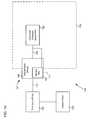
- FIG. 1Aillustrates a configuration 100 for providing television signals using an ESTB.
- the configuration 100includes a distribution point 104 in communication with a device 108 having demarcation capabilities via an external transport medium 112 .
- the external transport medium 112comprises a transport medium external to a customer premises 116 .
- the device 108is shown in FIG. 1A as including an ESTB 109 adapted to interface with an internal transport medium 124 .
- the internal transport medium 124comprises a transport medium internal to the customer premises 116 .
- the ESTB 109is shown as part of the demarcation device 108 , this is not a requirement. In other instances, the ESTB 109 may be distinct from, but coupled with, the demarcation device 108 , such as by using a modular design with plug-and-play technology. Other examples discussed below illustrate different ways in which the demarcation and ESTB devices 108 and 109 may be configured as integrated or separate devices. For convenience, however, the combination of the demarcation 108 device and ESTB 109 is sometimes referred to in a particular embodiment as an “set-top-box network interface device” (“SNID”) 107 irrespective of whether they are integrated or separate.
- SNIDset-top-box network interface device
- an SNIDmay correspond to one of a plurality of “application network interface devices” (“ANIDs”) that may be provided.
- An ANIDcorresponds generally to a combination of a network interface device and an application device, of which the ESTB 109 may be considered to be an example.
- an SNIDmay be considered to correspond specifically to an ANID that includes an ESTB as one of its application devices.
- the distribution point 104may be considered to be a source of telecommunication information transmitted to the customer premises and a recipient of telecommunication information transmitted from the customer premises; as described below, however, the distribution point 104 need not be either the ultimate source nor the ultimate recipient of telecommunication information.
- the distribution point 104may correspond to a telecommunication service provider's local office.
- the distribution pointmay correspond to another network element in the service provider's network, such as a remote termination cabinet and/or a digital subscriber line access multiplier (“DSLAM”). More generally, the distribution point 104 may correspond to any facility operated by a telecommunication service provider that is capable of transmitting telecommunication information to, and/or receiving telecommunication information from, a customer premises 116 .
- DSLAMdigital subscriber line access multiplier
- distribution pointscan be classified, inter alia, as discrete distribution points or complex distribution points. With respect to a particular information set, a discrete distribution point often transmits only the necessary or desired information to the SNID 107 . In contrast, a complex distribution point can transmit the entire information set to the SNID 107 .
- the contrastmay be illustrated with regard to video distribution: A discrete distribution point may perform channel switching (at the request of the demarcation device 108 ), encoding and sending only the desired channel information to the demarcation device 108 . In contrast, a complex distribution point might rely upon the demarcation device 108 to perform all channel switching.
- Distribution point 104can be capable of transmitting and/or receiving any type of telecommunication information to/from the SNID 107 , and such telecommunication information can be organized into a plurality of telecommunication information sets, as necessary.
- FIG. 1Adoes not show any additional sources or recipients of telecommunication information in communication with distribution point 104 , but, those skilled in the art will recognize that, in many embodiments, distribution point 104 can be coupled to multiple customer premises 116 (perhaps via an SNID 107 at each customer premises) and often is neither the ultimate source nor the ultimate recipient of telecommunication information.
- distribution point 104usually serves as an intermediary between one or more customer premises 116 and one or more larger telecommunication networks and/or telecommunication information providers, which, as discussed above, can include cable television networks, telephone networks, data networks, and the like. Further, many such networks (as well as, in some embodiments, distribution point 104 ) can be coupled to the Internet, so that distribution point 104 can serve as a gateway between customer premises 116 and any source and/or recipient of telecommunication information that has a connection to the Internet.
- distribution point 104can be configured to transmit telecommunication information to (and receive telecommunication information from) virtually any source or recipient of telecommunication information, through either direct or indirect (e.g., through the Internet) communication.
- a distribution point 104can transmit video signals received from a television programming provider to customer premises equipment, as described in the applications referenced above.
- distribution point 104can be in communication with one or more other customer locations, allowing for private virtual circuits, vlan tags and wavelengths, or rf connections between customer premises 116 and those locations.
- the SNID 107can serve as the interface between external transport medium 112 and customer premises 116 .
- the demarcation device 108 and the 109 comprised by the SNID 107are interfaced with the internal transport medium 124 , with the demarcation device interfaced with the external transport medium 112 , although other interfacing configurations are also within the scope of the invention.
- the ESTB 109may additionally be interfaced with the external transport medium 112 .
- the ESTB 109may also include a service interface 111 for addressing the ESTB 109 .
- the service interface 111may comprise a physical interface, such as a universal serial bus (“USB”), FireWire (IEEE 1394), registered jack 11 (“RJ-11”), registered jack 13 (“RJ-13”), registered-jack 45 (“RJ-45”), serial, coax, or other physical interface known to those of skill in the art.
- the service interface 111may comprise a logical interface, such as may be provided through a logical connection with an IP address.
- demarcation device 108 and/or ESTB 109may be attached to an external wall of the customer premises 116 . Such attachment may be performed of an integrated SNID 107 or may be performed with the components separately of a separated SNID 107 .
- Such a configurationprovides many advantages. For instance, if the telecommunication service provider desires to upgrade or otherwise change its network, including, perhaps, external transport medium 112 , a technician can perform any necessary changes at demarcation device 108 and/or ESTB 109 as appropriate without entering the customer premises.
- demarcation device 108 and/or ESTB 109may be located at a variety of alternative locations, and, as previously noted, an SNID 107 may also be divided, with different portions situated at different locations, according to the requirements of the implementation.
- the ESTB 109is configured so that it may communicate with CPE 120 , which may include a television device and may be located interior to the customer premises through internal transport medium 124 . Such communication is used to implement the ESTB 109 functionality with the CPE 120 in accordance with telecommunication information received from the distribution point 104 .
- the demarcation device 108may communicate directly with CPE 120 to implement other functions, including functions that may be defined by other applications comprised by the demarcation device 108 .
- the internal transport medium 124may comprise any of the media discussed above, in one embodiment it comprises existing wiring in customer premises 116 and, in some embodiments, is capable of carrying voice, data, and video information. For instance, as described in Edward H.
- telecommunication informationmay be transmitted via the reverse path to the distribution point 104 .
- telecommunication information received at the distribution point 104may be transmitted to an information recipient, such as a service provider.
- an information recipientsuch as a service provider.
- telecommunication information received at the distribution point 104may be transmitted across the Internet, such as may be used in the case of sending an email message where the ESTB 109 supports Internet functionality.
- the SNID 107can receive state information from a control point 128 , which is shown in the illustrated embodiment as associated with distribution point 104 .
- control point 128can be software and/or hardware operated by a telecommunication service provider for controlling certain features of the operation of the SNID 107 .
- control point 128can instruct the SNID 107 to provide (or cease to provide) particular applications and/or telecommunication services with the ESTB 109 to the customer premises 116 .
- Control point 128can also provide other directions to the SNID 107 through the demarcation device 108 , including, for instance, instructions to save or record a particular information set (e.g., data representing a movie), such that the information set may quickly (and, in some cases), repeatedly be transmitted to customer premises 116 , allowing the provision of voice, data, video, etc. on demand.
- a particular information sete.g., data representing a movie
- control point 128may have a web interface, such that the customer or any authorized person, such as an employee of the telecommunication service provider or telecommunication information provider, may log onto the web interface and configure options for the SNID 107 , perhaps resulting in state commands being transmitted from the distribution point 104 to the SNID 107 .
- control point 128can be a web interface to the SNID 107 itself, allowing the customer or other authorized person to configure the SNID 107 directly.
- control point 128can communicate with the SNID 107 through an application programming interface (“API”).
- APIapplication programming interface
- control point 128can interface with the SNID 107 through an API.
- the APIcorresponds to the service interface 111 of the application device.
- the APIcan include a set of software, hardware, or firmware routines or libraries that may be invoked programmatically to configure or relay information to the ESTB 109 .
- control point 128can be understood to be a program running on a computer, perhaps located at distribution point 104 or customer premises 116 , among other locations, that provides state information to the ESTB 109 via a software API.
- the APTmay be accessed locally, such as by a service technician.
- the service techniciancould visit property outside the customer premises 116 or a utility room in an MDU that is external to individual customer premises 116 , attach a laptop computer or other device to the physical service interface 111 , and upload information to the ESTB 109 , including state information and perhaps other telecommunication information.
- the ESTB 109can accept state information through other means, including, for example, through a web interface by receiving a specially formatted electronic message. This is especially the case in embodiments where the ESTB 109 is capable of acting as a web server, as discussed below.
- the addressability of the ESTB 109may be used in various embodiments to change the state of the ESTB 109 .
- state informationcan include any set of data or other information that may be interpreted by the ESTB 109 as defining operational instructions. This includes, for example, commands to process certain information sets in certain ways, e.g., to provide protocol conversion, to allow transmission of the information set, to deny transmission of the information set, to direct transmission on a particular interface, and the like, as well as commands to provide or cease providing a particular service, such as to provide access to a pay-per-view movie.
- a telecommunication service providercan control the services provided to a customer in several ways.
- the providercan only transmit a telecommunication information set to an SNID 107 if the user of that device is authorized to receive that information set.
- the service providercould send a plurality of information sets to a customer's SNID 107 , and rely on the state of the component ESTB 109 to determine access to those information sets that are authorized.
- control methodsare more well-suited to certain services than to others.
- the same set of informationmay be broadcast to many households, and the SNID 107 is well-suited to control access to those services, allowing for greater efficiency in the providing of such services.
- video-on-demand servicesmay instead be controlled at a distribution point 104 or elsewhere such that a particular SNID 107 only receives video-on-demand information if the customer already has requested and been authorized to receive that service. In such cases, the SNID 107 may not need to provide access control functions with respect to that service.
- the SNID 107can implement either of these access control schemes, or both in combination, as well as others. Moreover, the SNID 107 can, in some cases, be configured to support a plurality of schemes transparently. For instance, the customer could request a service from the SNID 107 , perhaps using one of the methods discussed above, and the SNID 107 could relay that request to the appropriate telecommunication service provider and/or telecommunication information provider, as well as reconfigure itself to allow access to that service, if necessary.
- the SNID 107can also be configured to take any necessary validating or authenticating action, such as notifying the distribution point 104 and/or control point 128 that the service has been requested, and, optionally, receiving a return confirmation that the service has been authorized.
- state information sent to the SNID 107can include one or more commands to interface with a particular CPE in a certain way. State information can further include instructions to modify one or more security settings of the SNID 107 .
- the SNID 107can include a computer virus scanner, and state information can include updated virus definitions and/or heuristics.
- the SNID 107often will be configured with access controls, such as to prevent unauthorized access through the SNID 107 by third parties.
- State informationcan include instructions on how to deal with particular third-party attempts to access the SNTD 107 or internal transport medium 124 .
- some security settingsmay specify the level of access the customer has to the functions of the SNID 107 , such as to prevent unauthorized use of certain telecommunication services, and that these settings also may be modified by received state information.
- the various access-control and security functionalities of the SNID 107discussed above may be implemented. In different embodiments, these functionalities may be performed by the demarcation device 108 , by the ESTB 109 , by a combination of the demarcation and ESTB devices 108 and 109 , and/or by still other supplementary application devices that may additionally be comprised by the SNID 107 . Moreover, the state information that manages such functionalities may sometimes be sent periodically to the SNID 107 to ensure that it is current. Those skilled in the art will also recognize that state information can be considered a subset of the broader category of telecommunication information.
- configuration 100 ′is illustrative of certain embodiments that can provide multiple ANIDs at customer premises 116 , at least of which may be an SNID 107 A.
- the SNID 107 Acomprises demarcation device 108 A and ESTB 109 A
- another ANID 107 Bcomprises demarcation device 108 B and application device 109 B.
- ANID 107 Bmay specifically not include an ESTB, so that all set-top-box functions are performed by SNID 107 A, although more generally ANID 107 B could also include an ESTB.
- the both the ESTB device 109 A and the other application device 109 Bare shown as separated from their respective demarcation devices 108 , although one or more of the multiple SNID or ANID may alternatively comprise structures in which they are integrated. In instances where the components are separated, the separate components may both be affixed to an exterior wall of the customer premises 116 . This has the same advantages discussed previously in connection with integrated SNIDs, namely ease of upgrading or otherwise changing the network by a telecommunication service provider.
- the separate componentsmay be provided in different locations, such as by providing the demarcation device 108 A or 108 B at a facility operated by the telecommunication service provider while keeping the ESTB 109 A or other application device 109 B on the exterior wall of the customer premises 116 .
- ESTB 109 Amay be in communication with CPE 120 A through internal transport medium 124 A and other application device 109 B may be in communication with CPE 120 B through internal transport medium 124 B.
- Implementation of the applications provided by ESTB 109 A and application device 109 Bcan thus be achieved respectively with telecommunication information received and transmitted by demarcation devices 108 A and 108 B.
- demarcation device 108 Acan be in direct communication with CPE 120 A through internal transport medium 124 A
- demarcation device 108 Bcan likewise be in direct communication with CPE 120 B through internal transport medium 124 B.
- Each of the SNID 107 A and ANID 107 Bmay be provided in communication with a common distribution point 104 through their respective demarcation devices 108 .
- demarcation device 108 Bcan communicate with distribution point 104 through external transport medium 112 B which, as illustrated by FIG. 1B , can simply be spliced into external transport medium 112 A, such as by using an active or passive splitting device, which could be optical, as in a fiber environment, or electrical.
- demarcation devices 108 and/or distribution point 104can include control logic to prevent unauthorized access by demarcation device 108 A to telecommunication information sent to or received from demarcation device 108 B, and vice versa.
- external transport medium 112 Bcould run directly from demarcation device 108 B to distribution point 104 .
- external transport medium 112 Bcould be omitted, with demarcation device 108 B coupled to demarcation device 108 A, which could then provide connectivity between demarcation device 108 B and distribution point 104 through external transport medium 112 A.
- ANID 107 Bcould comprise an SNID by including an ESTB as application device 109 B, such that separate SNIDs are provided for each separate resident or family.
- a single demarcation deviceperhaps with more interfaces, can service multiple dwelling or business units.
- demarcation devices 108 A, 108 Bcan include security functionality, for example to prevent telecommunication signals intended for CPE 120 A from reaching CPE 120 B and vice versa.
- demarcation devices 108can provide a variety of such security, encryption, and authentication functions.
- SNIDsare daisy-chained together, using any of the telecommunication media discussed herein. This allows a telecommunication service provider to provide service to additional customers without requiring any additional external transport media.
- SNIDs at multiple premisescan be coupled together, such that if the external transport medium coupled to one of the SNIDs fails, that device can maintain connectivity to the distribution point through its connection to another SNID.
- An SNID in accordance with specific embodimentsthus may have an interface for securely connecting to one or more additional SNIDs, and thus forming a mesh network of SNIDs and/or distribution points.
- This secure interfacecan be included, for instance, in a portion of the SNID that is inaccessible to customers, as illustrated in FIG. 2A and described below.
- configuration 100 ′′includes a distribution point 104 A coupled to an SNID 107 A via external transport medium 112 A and also includes a second distribution point 104 B coupled to an ANID 107 B via external transport medium 112 B.
- SNID 107 Aprovides an example of an SNID that includes a supplementary application device 109 C in addition to the ESTB 109 A.
- Each of these devices 109 A and 109 Cmay have a respective service interface 111 A and 111 C, and may be connected with different internal transport media 124 A or 124 C to reflect the different application capabilities.
- distribution point 104 Acould, for example, be associated with a cable television provider, while distribution point 104 B could be associated with a telephone company.
- configuration 100 ′′illustrates that multiple CPE 120 A and 120 C may be coupled with a single SNID 107 A. This may be done with multiple internal transport media 124 A and 124 C as illustrated by FIG. 1C , or may alternatively be done through a common internal transport medium as discussed below.
- the other application devices 109 B and 109 Cdo not comprise an ESTB, but in other embodiments they may.
- application device 109 Bcomprises an ESTB
- ANID 107 Bthus corresponds to a second SNID provided to customer premises 116 .
- SNID 107 Athus corresponds to a multi-ESTB SNID that may provide separate set-top-box capabilities to different CPE 120 A and 120 C.
- Each of these configurationsprovides a mechanism for providing separate set-top-box capabilities to different CPE within the customer premises, as may be desirable, for example, where different individuals wish to watch different pay-per-view programming on different televisions.
- an SNID 107can provide connectivity to a plurality of distribution points 104 A and 104 B, as well to a plurality of CPE 120 A, 120 B, and 120 C.
- the SNID 107is provided in a separated form with an ESTB 109 A and two other application devices 109 B and 109 C for providing supplementary application services.
- the ESTB 109 A and one of the other application devices 109 Bare provided external to the customer premises 116 and have service interfaces 111 A and 111 B.
- the second other application device 109 Cis provided interior to the customer premises, illustrating that it is not a requirement that all of the supplementary application devices comprised by the SNID 107 be disposed external to the customer premises 116 .
- the SNID 107corresponds to a multi-ESTB SNID that may provide separate set-top-box capabilities to different CPE 120 A and 120 B.
- application device 109 Ccould comprise an ESTB, whereby the overall arrangement comprises set-top-box capabilities not only in the external SNID 107 , but also comprises one or more set-top boxes interior to the premises.
- the connectivity of a single SNID 107 to a plurality of distribution points 104 A and 104 B and to a plurality of CPE 120 A, 120 B, and 120 Cmay be effected through attachments for multiple internal transport media 124 A, 124 B, and 124 C and for multiple external transport media 112 A and 112 B.
- each distribution point 104 A and 104 Bmay be associated with a different control point 128 A and 128 B, respectively.
- a single control point 128could provide configuration information to the SNID 107 with respect to both distribution points 104 A and 104 B.
- FIG. 1Eanother exemplary configuration 100 ′′′′ is presented in accordance with certain embodiments of the invention.
- the SNID 107is shown having a configuration similar to that of FIG. 1D , with a structure in which the demarcation-, ESTB-, and other application-device components are separated, including one of the other application devices 109 C in the interior of the customer premises 116 .
- FIG. 1Eshows an embodiment in which such communication is achieved with a common distribution point 104 .
- This distribution point 104which may be operated by a telecommunication service provider, can be in communication with one or more telecommunication information providers 130 A and 130 B.
- Each telecommunication information provider 130 A and 130 Bcan be the source or recipient of one or more telecommunication information sets, each of which may be associated with a particular telecommunication service.
- Each of the telecommunication information setsmay thus be transmitted to, or received from, the distribution point 104 .
- Distribution point 104can also transmit these information sets to, or received them from, the SNID 107 through demarcation device 108 , via external transport medium 112 .
- Such an configuration 100 ′′′′thus exploits a capability of the SNID 107 to process a plurality of such information sets in a variety of ways, as discussed below.
- each telecommunication information provider 130 A or 130 Bmay have an individual control point 128 B or 128 C.
- control points 128 B and 128 Ccan be in communication with the SNID 107 via distribution point 104 or, alternatively, could have a separate means of communication with the SNID 107 , such as via a modem and telephone line.
- the SNID 107can receive state information from each control point 128 B, and 128 C through the demarcation device 108 .
- state informationcan direct the behavior of the demarcation device 108 , ESTB I 09 A, and/or other application devices 109 B and 109 C comprised by the SNID 107 , in particular with respect to how to handle telecommunication information to implement various applications on the CPE 120 A, 120 B, and/or 120 C.
- state informationmay be received by the SNID 107 over the external transport medium 112 or through the service interfaces 111 A and 111 B of the ESTB 109 A and other application device 109 B.
- the SNID 107can be configured to accept state information related only to the telecommunication information and/or services provided by the telecommunication information provider sending the state information.
- the SNID 107can be protected against inadvertent or malicious misconfiguration, which could interrupt a telecommunication service provided by another telecommunication information provider.
- the SNID 107could be configured to automatically request updated state information from control point 128 A associated with distribution point 104 in the case of misconfiguration, and control point 128 A could maintain a master set of configuration information to be able to accommodate such a request.
- telecommunication information providers 130 A and 130 Bmay not have an associated control point.
- telecommunication information providers 130 A and 130 Bcan send state information to control point 128 A, perhaps via distribution point 104 A, and control point 128 A can relay that state information to the demarcation device 108 (again, perhaps through distribution point 104 ). In this way the telecommunication service provider can control which state information is transmitted to the SNID 107 .
- the demarcation device 108can submit a request for state information to one or more control points 128 A, 128 B, and/or 128 C, perhaps via distribution point 104 .
- a requestmight be made if, for instance, the customer would like to watch a pay-per-view movie.
- the appropriate control point, e.g., 128 B,could then provide the proper state information to the SNID 107 as described above, allowing transmission of the movie to customer premises 116 .
- embodiments of the inventionenable a single SNID 107 to serve multiple CPE 134 A-F, each of which can comprise a different appliance, at a single customer premises 136 .
- the flexibility provided by the SNID 107may be exemplified in an embodiment where the SNID 107 includes other application devices 109 B and 109 C in addition to the ESTB 109 A for providing a variety of supplementary application services.
- CPE 134 Acan be a television
- CPE 134 Bcan be a telephone
- CPE 134 Ccan be a video game system
- CPE 134 Dcan be a computer with an Ethernet interface
- CPE 134 Ecan be a computer with an HPNA interface
- CPE 134 Fcan be a laptop computer equipped with a wireless network card.
- the user functionality of each of these CPE examplesmay be enhanced with the ESTB 109 A and other application devices 109 B and 109 C comprised by the SNID 107 .
- the single SNID 107can support multiple network topologies.
- the SNID 107can serve as a hub for a point-to-point network topology, with multiple point-to-point connections to CPE 134 A and 134 B via internal transport media 138 A and 138 B, respectively.
- the SNID 107can support a bus topology, as illustrated by internal transport medium 140 , which can connect the SNID 107 to CPE 134 C, 134 D, and 134 E.
- the SNID 107can also be equipped with a wireless transmitter 142 for communication with wireless-capable CPE 134 F.
- the SNID 107can support a wide variety of networking media in customer premises 136 , including the existing telephone, satellite, cable, and network wiring.
- the existing telephone wiring in most homesis arranged in a bus topology, as is most coaxial cable (for instance RG 6 or RG 59 ) installed by cable television providers, although each may, in some implementations, be wired using a star topology.
- coaxial cablefor instance RG 6 or RG 59
- many homesalso have 10Base-T Ethernet networks, which sometimes require a central hub.
- 10Base-Tcan be understood to include newer implementations of Ethernet over unshielded twisted pair wiring, including, for instance, 100 megabit Ethernet (100Base-T, 100VG-AnyLAN, etc.) and gigabit Ethernet (1000Base-T) standards.
- the SNID 107can support these and other network topologies, serving as the hub in a 10Base-T network if necessary.
- FIG. 1Gillustrates another exemplary configuration 150 for using an SNID 151 in an xDSL implementation, according to certain embodiments of the invention.
- distribution point 154can comprise a host digital terminal 156 coupled by transport medium 158 to DSLAM 160 .
- DSLAM 160can be considered the distribution point.
- Host digital terminal 156can be coupled to any of a variety of data sources and/or recipients, either directly, or indirectly, such as through the provider's network and/or the Internet.
- transport medium 158can be a Synchronous Optical NETwork (“SONET”) link (e.g., OC-3, OC-12, etc.), although those skilled in the art will recognize that other suitable transport media may be substituted.
- SONETSynchronous Optical NETwork
- distribution point 154also comprises a central office shelf 162 in communication with the PSTN 164 , as well with an asynchronous transfer mode (“ATM”) network 166 , either of which can provide connectivity to any of the variety of data sources and/or recipients discussed above.
- shelf 162is, in turn, coupled to fiber distribution panel 168 , which is connected by transport medium 170 to a digital loop carrier remote termination cabinet 172 .
- Remote termination cabinet 172can also be coupled to DSLAM 160 by transport medium 174 , which may be routed through serving area interface 176 .
- transport medium 174can carry one or more POTS information sets
- transport medium 158can carry one or more non-POTS (in this case xDSL) information sets.
- these two information setscan be combined at DSLAM 160 , which is in communication with serving area interface 176 through transport medium 178 .
- Serving area interface 176can be coupled to demarcation device 152 of SNID 151 with transport medium 180 .
- the SNID 151comprises an ESTB 155 and a plurality of other application devices 153 , the combination being adapted to provide set-top-box and other application functions to various equipment within the customer premises 182 .
- the SNID 151is fixedly attached to an exterior wall at the customer premises 182 .
- the ESTB 155 and other application devices 153 of the SNID 151may then be coupled via one or more internal transport media 184 A-G to a variety of CPE, including without limitation a television set 186 , a video phone 188 , an analog (POTS) telephone 192 , an IP-compatible phone 194 , and a personal computer 196 .
- a television set 186a video phone 188
- POTSanalog
- IP-compatible phone 194an IP-compatible phone 194
- personal computer 196a personal computer 196 .
- an SNID 151can be used to provide a plurality of telecommunication services to a customer premises, including set-top-box functions.
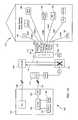
- FIGS. 2A and 2BOne exemplary embodiment of an SNID 200 is illustrated in FIGS. 2A and 2B .
- FIG. 2Aprovides a top view that explicitly shows components within the SNID 200
- FIG. 2Bprovides a side view that shows the logical organization of the SNID 200 without the components.
- SNID 200comprises a clamshell design, with a lid portion 204 and a body portion 208 connected by hinges 212 A and 212 B.
- the body portion 208comprises a network area 216 and a customer area 220 .
- network area 216is adapted to receive a cover and is designed generally to be accessible only to personnel authorized by the telecommunication service provider.
- the customercan access customer area 220 to add or remove components as desired.
- the SNID 200serves to isolate the telecommunication service provider's network from the customer's network, as described above.
- the SNID 200can include a first interface 228 for communicating with the provider's external transport medium.
- the external transport mediummay comprise the twisted-pair copper “local loop” running from the customer's premises to the telecommunication service provider's local office, and interface 228 will allow for the attachment of the local loop to the SNID 200 .
- the external transport mediumcan be any of a variety of other media, including satellite transmissions, wireless transmissions, coaxial cable, and the like.
- the external transport mediumcan comprise multiple transport media (of the same or different types), for which the SNID 200 could include multiple interfaces.
- the SNID 200can function to couple a plurality of external transport media to one another, seamlessly increasing the bandwidth available to the customer premises.
- a customer premisesmight have a satellite link to one telecommunication service provider and an ADSL link to another provider, and the SNID 200 could combine or multiplex these two links to provide an apparent single, higher-bandwidth to the customer premises.
- a particular external transport mediumsuch as a satellite link
- the SNID 200could use a second external transport medium, such as an ADSL link, to allow transmission in the other direction.
- Interface 228can be coupled to a discrimination device 232 , which can be operative to separate information sets received on interface 228 , and, conversely, aggregate information sets for transmission on interface 22 ).
- discrimination device 232can separate POTS information from other telecommunication information and/or isolate signals on the internal transport medium from the external transport medium and vice versa.
- discrimination device 232can comprise one or more filters. Such filters can include, but are not limited to, high-pass, low-pass, and/or band-pass filters.
- discrimination device 232might include a high-pass and/or low-pass filter for separating high-frequency (e.g., data) from low frequency (e.g., POTS) information.
- discrimination device 232can comprise many other types of filters, including both digital and analog filters.
- Discrimination device 232can be operable to separate information sets through a variety of criteria, including for example, by frequency, by destination device, information type, and/or frequency.
- information setscan be multiplexed (for instance, using various time-division multiplexing or wave-division multiplexing schemes known in the art) for transmission over an external transport medium
- discrimination device 232can comprise a demultiplexer capable of separating multiplexed signals and, optionally, routing each signal to the necessary destination.
- discrimination device 232is in communication with a second interface 236 , which can interface with the telephone wires at the customer premises to provide traditional analog telephone service.
- an aggregator 240can be situated between discrimination device 232 and interface 236 to allow additional, perhaps non-POTS, information sets to be sent and received through interface 236 simultaneously with the POTS information. This can include, for example, aggregating information sets for transmission of an HPNA signal over an internal transport medium.
- the discrimination devicecan also be coupled to a processing system 244 , which in the illustrated embodiment is located in the lid portion 204 , and all non-POTS information sets can be routed to processing system 244 for additional processing.
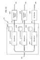
- Processing system 244is described in detail below, but can, in general, comprise one or microprocessors, including digital signal processor (“DSP”) chips, memory devices, including both volatile and nonvolatile memories, and storage devices, including hard disk drives, optical drives and other media.
- processing system 244can comprise the equivalent of one or more personal computers, running any of a variety of operating systems, including variants of Microsoft's WindowsTM operating system, as well as various flavors of the UNIXTTM operating system, including open source implementations such as the several LinuxTM and FreeBSDTM operating systems.
- Telecommunication information or information setscan be processed by processing system 244 in a variety of ways, including, for example, routing a given information set to a particular interface, transforming information such as by encoding and/or decoding information and converting between different transport protocols, storing information, filtering information, and any of the other functions described herein with respect to processing systems.
- processing system 244can serve as the termination point for an external transport medium; for instance processing system 244 can incorporate the functionality of an xDSL modem.
- processing system 244can serve to identify quality-of-service requirements (for instance, latency requirements for voice transmissions and bandwidth requirements for streaming media transmissions, to name a few) and enforce those requirements, ensuring that sufficient bandwidth is provided to a particular device, network segment or application to maintain the quality of service required.
- quality-of-service requirementsfor instance, latency requirements for voice transmissions and bandwidth requirements for streaming media transmissions, to name a few
- an SNIDmay comprise another interface in communication with a second distribution point 104 B through an additional external transport medium 112 A, perhaps operated by a different telecommunication service provider.
- the additional external interfacecould be coupled to discrimination device 232 , or it could be coupled to another discrimination device, which could also be in communication with processing system 244 , interface 236 and/or aggregator 240 .
- a single SNIDto serve as a communication gateway between the customer premises and multiple telecommunication service providers, including combining or multiplexing multiple external transport media (each of which may be in communication with a different telecommunication service provider and/or telecommunication information provider) as discussed above.
- processing system 244is in communication with aggregator 240 , which, as discussed above, can aggregate non-POTS information sets received from processing system 244 and POTS information sets received directly from discrimination device 232 for consolidated transmission via interface 236 .
- discrimination device 232 and aggregator 240can function to separate telecommunication information received on interface 228 into a set of POTS telecommunication information and a set of non-POTS telecommunication information.
- POTS informationcan be understood to include ordinary telephone signals, and non-POTS information can be understood to include all other telecommunication information).
- the non-POTS informationis routed via transport medium 248 to processing system 244 for processing, and the POTS information is routed to interface 236 for transmission to the internal transport medium.
- one or more sets of non-POTS informationcan be routed to interface 236 using transport medium 252 for transmission through interface 236 , perhaps in combination with one or more sets of POTS information.
- discrimination device 232 and aggregator 240can perform the same function in reverse, i.e., to separate and recombine different sets of telecommunication information received on interface 236 from the customer's premises.
- both discrimination device 232 and aggregator 240each can perform a combined discrimination-device-aggregator function, depending on the direction of information flow.
- discrimination device 232 and/or aggregator 240can be incorporated into processing system 244 ; likewise discrimination device 232 can incorporate interface 228 and/or aggregator 240 can incorporate interface 236 , such that discrimination device 232 and/or aggregator 240 comprise the necessary components to be coupled directly to the external and internal transport media, respectively.
- Discrimination device 232 and/or aggregator 240can also serve another function in certain embodiments: Since the external transport medium is coupled to first interface 228 and the internal transport medium can be coupled to, inter alia, second interface 236 , the discrimination device 232 and/or aggregator 240 can serve as an isolation device for intermediating between the two media, such that when a topological change occurs in one of the media, only the SNID interface need be changed, and the other transport medium is not affected. In some such embodiments, discrimination device 232 and/or aggregator 240 can serve to intermediate (including protocol translation and the like) between interfaces 232 , 240 , allowing either the internal or the external transport medium to be upgraded or changed without impacting the other transport medium. Of course, in certain embodiments, this isolation function also could be performed by processing system 244 . In yet other embodiments, the isolation device might comprise a separate piece of hardware in communication with discrimination device 232 , aggregator 240 and/or processing system 244 .
- the SNID 200comprises an ESTB 246 A, and may also comprise one or more other application devices 246 B and 246 C to implement supplementary applications.
- the ESTB 246 A and other application devicesare usually disposed in the network area 216 , but as illustrated for other application device 246 B, they may sometimes be disposed in the customer area 208 to permit access by the customer.
- the ESTB 246 Ais provided in communication with the processing system 244 by transport medium 268 .
- the other application devices 246 B and 246 Cmay also be provided in communication with the processing system 244 by transport media 251 and 263 .
- the ESTB 246 Ais also in communication with interface 260 over transport medium 269 , which allows communication with the transport media internal to the customer premises.
- interface 260could be a coaxial interface for connection to RG6 and/or RG59 cable. Similar communication with the transport media internal to the customer premises may also be provided in some embodiments for application devices providing supplementary services.
- application devicesproviding supplementary services.
- Such an exampleis illustrated with other application device 246 B in communication with interface 256 over transport medium 264 .
- interface 256could be an RJ45 and/or RJ11 interface for connection to unshielded twisted pair cable, which can, for instance, form a 10Base-T Ethernet network.
- the information set that includes the encoded video signalscan be routed by discrimination device 232 to processing system 244 .
- the signalscan be decoded into RF-modulated NTSC, HDTV, PAL and/or SECAM format for transmission via transport medium 269 to coaxial interface 260 , where it can be transmitted via coaxial cable to one or more televisions at the customer premises.
- informationmight be routed from the application device 246 C through the aggregator 240 .
- Such an arrangementmay be suitable for supplementary applications that use IP data, such as a VoIP application.
- the SNID 200might receive IP data combined with television information and perhaps also other types of telecommunication information, on interface 228 .
- the information setscan be routed by the discrimination device 232 via medium 248 to processing system 244 , where they can be processed.
- Television informationcould then be routed via transport medium 268 to the ESTB 246 A for subsequent delivery of that information through interface 260 in accordance with the level of service subscribed for by the customer.
- premium television channelsmay or may not be decoded by the ESTB 246 A and pay-per-view programming may or may not be transmitted by the ESTB 246 A depending on the service level.
- Similar types of routing and processingmay be performed for supplementary applications as well. It will be appreciated that it many instances the supplementary applications act to enhance the functionality provided by the ESTB 246 A. In other instances, the supplementary applications provide functionality in the customer premises that is not directly related to the ESTB 246 A functions, but which is conveniently coordinated by the SNID 200 . For instance, if other application device 246 C comprises a VoIP application device, the corresponding IP data information set received at the processing system 244 could be extracted and routed to other application device 246 C over transport medium 251 . It may then be provided to the customer's existing telephone wiring using interface 236 , optionally in conjunction with aggregator 240 and/or one or more line drivers.
- the SNIDcan allow virtually unlimited connectivity options for each CPE at the customer premises, in addition to providing the set-top-box functionality.
- the processing system 244could include components to serve, for example, as a cable or xDSL modem, as well as components to serve as an Ethernet hub, switch, router, or gateway, the functions of each of which are familiar to those of skill in the art.
- One supplementary application device 246 B or 246 C that may be includedis a digital-recorder application device, which could provide a mechanism for digital recording of all forms of information incoming to the SNID 200 and make them accessible to a user at the customer premises.
- the information that could be recordedincludes video, data, voice, among other types of information.
- Another supplementary application device 246 B or 246 C that may be includedis a digital storage application device, which could provide a supplementary mechanism for storing information presented to user applications.
- the information that could be storedalso includes video, data, voice, and other types of information.
- the combination of a digital-recorder application device and a digital-storage application device in an SNID 200may be used conveniently to provide primary and secondary information-storage capabilities.
- a digital-recorder applicationcould be used to provide a primary, on-line, video storage capability while a digital-storage application could be used to provide a secondary, off-line, video storage capability.
- Still other supplementary application devicescould be included to enhance such functionality further, such as a hard-drive application device to permit expandable storage capabilities.
- supplementary application devices 246 B or 246 Cwhose functions may be conveniently coordinated include digital-asset application devices.
- one of the other application devices 246 B or 246 C in the SNID 200could comprise a digital-asset sharing application device to permit sharing of information among equipment within the customer premises. Such an asset-sharing capability may be used within the customer premises to share video, data, electronic books, games, music, and the like.
- Another of the other application devices 246 B or 246 Ccould comprise a digital-asset caching application device to permit storage and distribution of digital assets.
- a further supplementary application device 246 B or 246 Ccould comprise a digital-asset protection application device to control the distribution of digital assets in accordance with legal restrictions, such as those derived from copyright ownership.
- the other application devices 246 B or 246 Cmay comprise application devices for effecting various voice-related applications within a customer premises.
- a voice application devicecould include functionality to provide such functions as telephone caller identification, call logs, voice mail-storage, voice-mail retrieval, call waiting, solicitation barriers, and the like.
- a VoIP application devicecould provide support for VoIP functions within the customer premises.
- Still further supplementary application devices 246 B or 246 Cthat may be used include various types of informational applications.
- an online digital guide application devicecould be used to provide a digital data guide for television, music, and other types of programming. Such a data guide could be provided alternatively in real time or in non-real-time.
- a further example of an informational applicationcould be realized with a home-utilities application device adapted to provide monitoring and/or billing tracking functions for utilities used within the customer premises. In this way, the use and/or cost of electricity, gas, water, and other utilities may be monitored by the customer.
- a diagnostic-interface application devicemay be provided to permit diagnostic functions of equipment within the customer premises, thereby permitting the customer to obtain information on the functioning of such equipment.
- Other application devices 246may provide security functions.
- a data security application devicemay be used to provide hacker protection for the home, responding to identified attempts to breach the security of the customer premises.
- a home-security application devicecould be provided to monitor the physical security of the customer premises. Such a home-security application device would typically be provided with an interface to door and window monitors to determine whether they are open or shut, and with an interface to motion detectors, glass-breaking detectors, and other physical security equipment known to those of skill in the art.
- the ESTB 246 A and each of the supplementary application devices 246 B or 246 C in the SNIDmay include a service interface 277 to permit their states to be changed and/or updated.
- such interfacesmay comprise physical interfaces such as USB, FireWire (IEEE 1394), RJ-11, RJ-45, serial, coaxial, or other physical interfaces, to permit a service technician to interact with the ESTB 246 A or supplementary application devices 246 B or 246 C while at the site of the SNID 200 .
- the service interfacesmay comprise logical interfaces to permit IP addressing to be used in changing the state of the application devices.
- the SNID 200may also include a future-application device with open architecture to support new applications. The architecture may be configured by use of the service interfaces 277 when the new application is implemented.
- SNID 200can comprise a line driver (not shown on FIG. 2A or 2 B), coupled to processing system 244 and aggregator 240 .
- the line drivercan function to allow conversion between various network formats and media, allowing a variety of different media types, e.g., twisted pair and/or coaxial cable, in accordance with the HPNA and HPNA+ standards, as well, perhaps, as the customer premises' A/C wiring, in accordance, for example, with the HomePlugTM standard, to transport combined POTS and non-POTS information sets.
- SNID 200can comprise a power supply 272 for providing electrical power to the components in SNID 200 .
- Power supply 272can be powered through electrical current carried on the external transport medium and received on interface 228 .
- power supplycan receive electrical current from a coaxial interface, such as interface 256 , or through a dedicated transformer plugged into an AC outlet at customer premises, e.g., through 12V connection 276 .
- Processing system 244can be powered by a connection 280 to power supply 272 , or through one or more separate power sources, including perhaps the A/C power of the customer premises. In some embodiments, processing system 244 might have its own power supply.
- processing system 244can comprise a plurality of processing devices, and each processing device can comprise multiple components, including microservers, memory devices, storage devices and the like.
- a “microserver”is intended to refer to any device programmed to perform a specified limited set of functions, such as an EPROM.
- FIG. 2Cprovides a detailed illustration of an exemplary processing system 244 , which comprises multiple processing devices 291 .
- transport medium 248links processing system 244 with an external transport medium, perhaps via a discrimination device and/or interface, as described above.
- Transport medium 248can be coupled to a plurality of microservers 291 such that any information received by the processing system 244 via transport medium 248 may be routed to any of the microservers 291 .
- Each microservercan, in some embodiments, be the equivalent of a server computer, complete with memory devices, storage devices, and the like, each of which is known in the art.
- FIG. 2Cstorage devices 293 associated with each of the microservers 291 are shown.
- One of the microservers 291 Amay be associated with the ESTB 246 A and each of the other microservers 291 B and 291 C may be associated with a respective one of the supplementary application devices 246 B or 246 C.
- the supplementary microservers 291 B and 291 Cmay individually be adapted to function as, for example, HTML microservers, authentication microservers, FTP microservers, TFTP microservers, DHCP microservers, WebServer microservers, email microservers, critical alert microservers, home-security microservers, VPN microservers, advertising microservers, instant-messaging microservers, wireless microservers, rf microservers, test-access microservers, data-security microservers, and the like.
- microservers 291can be configured to route information sets received via transport medium 248 , according to the type of telecommunication information in the set (e.g., encoded video, IP data, etc.) as well as any addressing information associated with either the set or the information it comprises (e.g., a specified destination port or network address for a particular subset of telecommunication information). In this way, microservers 291 can serve switching functions somewhat similar to that described with respect to discrimination device 232 described in relation to FIG. 2A . For instance, if television-signal data is received by microserver 291 A, such data can be routed to the ESTB 246 A for decoding and transmission as appropriate according to subscription service levels.
- the type of telecommunication information in the sete.g., encoded video, IP data, etc.
- any addressing information associated with either the set or the information it comprisese.g., a specified destination port or network address for a particular subset of telecommunication information.
- microservers 291can serve switching functions somewhat
- microserver 291 Bif IP data is received by microserver 291 B, such data can be routed to an Ethernet connection, to the existing telephone wiring, e.g., in an HPNA implementation, or to any other appropriate medium, perhaps via an appropriate line driver.
- processing system 244and in particular one or more of microservers 291 , can incorporate the functionality of discrimination device 232 and/or aggregator 240 , rendering those components optional.
- one or more of the microserversmay be adapted to function as a controller for the SNID 200 , overseeing the SNID's state and monitoring performance.
- the controller functionscan be accessed using a web browser.
- Processing system 244can have multiple means of input and output.
- microservers 296can communicate with one or more external transport media (perhaps, as discussed above, via intermediary devices) using one or more transport media (e.g., 248 ).
- Processing system 244also can communicate with one or more internal transport media via a variety of information conduits, such as category 5, 5e and/or 6 unshielded twisted pair wire 268 , RG6 and/or RG59 coaxial cable 264 , and category 3 unshielded twisted pair copper (telephone) wire 252 , again possibly via intermediary devices, as discussed with reference to FIG. 2A .
- processing system 244can include interfaces for multiple transport media of a particular type, for instance, if processing system 244 serves as a networking hub, switch or router.
- Processing system 244can also have infra-red and radio-frequency receivers and transmitters, for instance to allow use of a remote control device, as well as wireless transceivers, for instance to allow wireless (e.g., IEEE 802.11) networking.
- FIG. 2Dprovides an exemplary architecture for the ESTB 246 A that may be used in embodiments of the invention.
- the components in this exemplary architectureare provided for purposes of illustration and it will be appreciated that additional or fewer components may be provided in alternative embodiments.
- Signals incoming to the ESTB 246 A over transport medium 268may be directed to one of a plurality of decoders, shown to include an analog decoder 281 suitable for decoding analog television signals, a digital MPEG decoder 282 suitable for decoding digital television signals, and an IP decoder 283 suitable for decoding IP signals.
- the analog decoder 281may receive composite analog video signals that it separates as red, green, blue, and sync (“RGBS”) signals, using the NTSC, PAL, or SECAM standards as may be appropriate.
- the digital decoder 282may receive digital audio and video signals, which are decompressed according to the MPEG-2 or a related standard, such as MPEG-1 or MPEG-4.
- the IP decoder 283may be used in applications discussed below that are integrate IP functions within the ESTB 246 A.
- the processor 284controls operation of the decoders 281 , 282 , and 283 to receive signals decoded from the incoming signals and to transmit suitable signals to an encoder 286 according to appropriate service-level conditions.
- the encoder 286converts the individual components of signals into composite signals for display on a television, transmitting the composite signals over transport medium 269 .
- the encoder 286could combine luminance Y and chrominance C signals to produce a video image, or could perform encoding according the NTSC, PAL, or SECAM standards.
- the encodermay also act to synchronize video and audio streams in producing the television signals.
- the ESTB 246 Amay itself include a buffer 285 in communication with the processor for implementing personal-video-recording (“PVR”) functionality within the ESTB 246 A.
- PVRpersonal-video-recording
- SNIDcan provide several benefits, including simultaneous video, data and voice transmission, while maintaining required Quality of Service levels for each particular information set.
- some embodiments of the SNIDcan comprise a router that is capable of multi-protocol label switching (“MPLS”), which, those skilled in the art will recognize, allows the telecommunication service provider tremendous flexibility in designing the architecture of the external transport medium, including options, such as “Ethernet in the last mile” and tag switching, that provide enhanced features and performance across the provider's network.
- MPLSmulti-protocol label switching
- Various embodiments of the SNIDalso allow for a plurality of virtual private networks to be established through the SNID, allowing one or more secure data connections from the customer premises to other locations.
- the ESTBmay be used to provide middleware support, programming guides, pay-per-view functionality, video-on-demand functionality, encryption and decryption support for video signals and authentication functions, billing interfaces, closed-captioning functionality, macrovision functionality, and the like.
- the ESTBmay provide various forms of management support, including fault monitoring, internal ESTB monitoring, remote reboot support, remote shutdown, and the like.
- FIG. 3provides a summary of several such embodiments. Since specific details of how each of the steps shown in FIG. 3 may be implemented have been provided in detail above, these steps are described relatively briefly in connection with FIG. 3 .
- a transport medium internal to a customer premisesis isolated from transport media external to the customer premises. Such isolation permits a flow of telecommunication information between the internal and external transport media to be mediated by the SNID.
- telecommunication informationis received from a first transport medium external to the customer premises, such as by the SNID.
- this telecommunication informationis provided to the ESTB, which is located external to the customer premises so that the ESTB may decode it according to the format in which it is received at block 316 .
- a television signalis generated by subsequently encoding the information at block 320 according to NTSC, PAL, SECAM, or similar formats.
- Subsequent actions taken by the ESTBmay depend on a level of service that the ESTB is configured to provide to a particular customer premises, as checked at block 324 . For example, if the service level includes providing access to regular television programming and the received telecommunication information includes such regular programming, the corresponding television signal is provided to the internal transport medium at block 328 . Similarly, if the service level includes providing access to certain premium television programming and the received telecommunication information includes that premium programming, the corresponding television signal is provided to the internal transport medium at block 332 .
- the service levelmay include providing access to a certain pay-per-view program; usually such a service level is of short duration and in response to a specific request transmitted to the ESTB in accordance with the nature of pay-per-view programming.
- the corresponding television signalis provided to the internal transport medium at block 336 .
- the ESTBmay also provide PVR functionality in some embodiments, as indicated at block 340 .
- Such functionalitymay make use of a buffer data-storage facility included within the ESTB and is implemented by responding to interactivity between the ESTB and the internal transport medium.
- instructions from a user transmitted over the internal transport medium to the ESTBmay cause the ESTB to change the manner in which television signals are transmitted.
- the ESTBmay write information to the buffer data-storage facility, may transmit information from the buffer at normal speed, increased speed, or in reverse order, and may pause transmission. In this way, the user is provided with the ability to control transmission of the television signals by pausing, fast-forwarding, rewinding, and the like.
- this functionalitymay be provided in concert with a remote-controlled signalling in which the ESTB is equipped with the capacity to be controlled with a remote transmitter.
- multiple remote transmitters within the customer premisesmay be equipped to control the ESTB, with addressibility of the remote transmitters being used by the ESTB to distinguish them.
- infrared-over-coax signallingcould be used with an addressable controller that receives infrared signals from the transmitters, converts the signals, and transmits them back to the SNID.
- Such interactivitymay also be used in providing web-browsing functionality, as indicated at block 344 .
- Such functionalitymay be provided in those embodiments where the ESTB includes an IP decoder with which the web-browsing capability may be implemented.
- the ESTBacts as an interface between the internal transport medium, onto which a user puts instructions for accessing particular web sites, transmitting information to those web sites, downloading information from those web sites, and the like, and the external transport media, from which corresponding information is retrieved or onto which corresponding information is transmitted.
- This functionalitypermits, for example, such users to engage in electronic commerce and other applications.
- the ESTBmay be configured to provide data-caching functionality in some embodiments.
- the ESTBcould be configured automatically to receive certain subscription data, such as news, shopping catalogs, brochures, premium programming, web pages, magazines, and the like, and to write such data to a data-storage facility comprised by the SNID. The user could then access such information at her convenience.
- the ESTBcould be configured automatically to overwrite old information with new information as it is received so that the user always has access to the most recent “issue” of her subscription.
- the right columnindicates that this functionality may be enhanced and/or integrated with supplementary functionality in various embodiments.
- a state of the ESTBmay be used, for example, to change service levels so that more or fewer of the functions described in connection with the left column become accessible to a specific customer premises.
- Such changes in statemay be made for indefinite periods of time or may be more transient, such as in the case of providing a pay-per-view program, in which case the change in state may be effected only for approximately the length of the program.
Landscapes
- Engineering & Computer Science (AREA)
- Signal Processing (AREA)
- Multimedia (AREA)
- Computer Networks & Wireless Communication (AREA)
- Computer Hardware Design (AREA)
- Computer Security & Cryptography (AREA)
- Computing Systems (AREA)
- General Engineering & Computer Science (AREA)
- Two-Way Televisions, Distribution Of Moving Picture Or The Like (AREA)
Abstract
Description
Claims (29)
Priority Applications (9)
| Application Number | Priority Date | Filing Date | Title |
|---|---|---|---|
| US10/444,941US8713617B2 (en) | 2003-01-31 | 2003-05-22 | Systems and methods for providing television signals using a network interface device |
| US10/624,454US7793003B2 (en) | 2003-01-31 | 2003-07-21 | Systems and methods for integrating microservers with a network interface device |
| US10/676,429US8490129B2 (en) | 2003-01-31 | 2003-09-30 | Methods, systems and apparatus for selectively distributing urgent public information |
| US10/676,418US7194249B2 (en) | 2003-01-31 | 2003-09-30 | Methods, systems and apparatus for providing urgent public information |
| US10/854,738US8050281B2 (en) | 2003-01-31 | 2004-05-25 | Alert gateway, systems and methods |
| US11/670,923US7389104B2 (en) | 2003-01-31 | 2007-02-02 | Methods, systems and apparatus for providing urgent public information |
| US12/841,877US20100299407A1 (en) | 2003-01-31 | 2010-07-22 | Systems and Methods for Integrating Microservers with a Network Interface Device |
| US13/243,706US9542830B2 (en) | 2003-01-31 | 2011-09-23 | Alert gateway, systems and methods |
| US13/915,930US10362468B2 (en) | 2003-01-31 | 2013-06-12 | Methods, systems and apparatus for selectively distributing urgent public information |
Applications Claiming Priority (5)
| Application Number | Priority Date | Filing Date | Title |
|---|---|---|---|
| US10/356,338US8537814B2 (en) | 2003-01-31 | 2003-01-31 | Configurable network interface device and systems and methods for its use |
| US10/356,688US7454006B2 (en) | 2003-01-31 | 2003-01-31 | Systems, methods and apparatus for providing a plurality of telecommunication services |
| US10/356,364US7180988B2 (en) | 2003-01-31 | 2003-01-31 | Packet network interface device and systems and methods for its use |
| US10/367,597US7433465B2 (en) | 2003-01-31 | 2003-02-14 | Systems and methods for providing application services |
| US10/444,941US8713617B2 (en) | 2003-01-31 | 2003-05-22 | Systems and methods for providing television signals using a network interface device |
Related Parent Applications (5)
| Application Number | Title | Priority Date | Filing Date |
|---|---|---|---|
| US10/356,338Continuation-In-PartUS8537814B2 (en) | 2003-01-31 | 2003-01-31 | Configurable network interface device and systems and methods for its use |
| US10/356,688Continuation-In-PartUS7454006B2 (en) | 2003-01-31 | 2003-01-31 | Systems, methods and apparatus for providing a plurality of telecommunication services |
| US10/356,364Continuation-In-PartUS7180988B2 (en) | 2003-01-31 | 2003-01-31 | Packet network interface device and systems and methods for its use |
| US10/367,597Continuation-In-PartUS7433465B2 (en) | 2003-01-31 | 2003-02-14 | Systems and methods for providing application services |
| US10/448,249Continuation-In-PartUS20040163126A1 (en) | 2003-01-31 | 2003-05-29 | Methods and apparatus for delivering a computer data stream to a video appliance with a network interface device |
Related Child Applications (6)
| Application Number | Title | Priority Date | Filing Date |
|---|---|---|---|
| US10/367,597Continuation-In-PartUS7433465B2 (en) | 2003-01-31 | 2003-02-14 | Systems and methods for providing application services |
| US10/377,281Continuation-In-PartUS20040150748A1 (en) | 2003-01-31 | 2003-02-27 | Systems and methods for providing and displaying picture-in-picture signals |
| US10/624,454Continuation-In-PartUS7793003B2 (en) | 2003-01-31 | 2003-07-21 | Systems and methods for integrating microservers with a network interface device |
| US10/676,418Continuation-In-PartUS7194249B2 (en) | 2003-01-31 | 2003-09-30 | Methods, systems and apparatus for providing urgent public information |
| US10/676,429Continuation-In-PartUS8490129B2 (en) | 2003-01-31 | 2003-09-30 | Methods, systems and apparatus for selectively distributing urgent public information |
| US11/670,923Continuation-In-PartUS7389104B2 (en) | 2003-01-31 | 2007-02-02 | Methods, systems and apparatus for providing urgent public information |
Publications (2)
| Publication Number | Publication Date |
|---|---|
| US20040163125A1 US20040163125A1 (en) | 2004-08-19 |
| US8713617B2true US8713617B2 (en) | 2014-04-29 |
Family
ID=32931688
Family Applications (1)
| Application Number | Title | Priority Date | Filing Date |
|---|---|---|---|
| US10/444,941Active2030-06-02US8713617B2 (en) | 2003-01-31 | 2003-05-22 | Systems and methods for providing television signals using a network interface device |
Country Status (1)
| Country | Link |
|---|---|
| US (1) | US8713617B2 (en) |
Cited By (6)
| Publication number | Priority date | Publication date | Assignee | Title |
|---|---|---|---|---|
| US20170303009A1 (en)* | 2013-04-05 | 2017-10-19 | Media Global Links Co., Ltd. | Ip uncompressed video encoder and decoder |
| US9807459B2 (en) | 2015-05-14 | 2017-10-31 | At&T Intellectual Property I, L.P. | Media interface device |
| US10136470B2 (en) | 2012-07-05 | 2018-11-20 | Centurylink Intellectual Property Llc | Multi-service provider wireless access point |
| US10142023B2 (en) | 2003-01-31 | 2018-11-27 | Centurylink Intellectual Property Llc | Antenna system and methods for wireless optical network termination |
| US10362468B2 (en) | 2003-01-31 | 2019-07-23 | Centurylink Intellectual Property Llc | Methods, systems and apparatus for selectively distributing urgent public information |
| US10462846B2 (en) | 2012-07-05 | 2019-10-29 | Centurylink Intellectual Property Llc | Multi-service provider wireless access point |
Families Citing this family (32)
| Publication number | Priority date | Publication date | Assignee | Title |
|---|---|---|---|---|
| US7725919B1 (en)* | 2002-05-23 | 2010-05-25 | Microsoft Corporation | Manage content in a short-term content buffer with content identifiers |
| US7954127B2 (en)* | 2002-09-25 | 2011-05-31 | The Directv Group, Inc. | Direct broadcast signal distribution methods |
| US7474742B2 (en)* | 2003-01-31 | 2009-01-06 | Qwest Communications International Inc. | Environmentally-controlled network interface device and methods |
| US7921443B2 (en) | 2003-01-31 | 2011-04-05 | Qwest Communications International, Inc. | Systems and methods for providing video and data services to a customer premises |
| US8050281B2 (en)* | 2003-01-31 | 2011-11-01 | Qwest Communications International Inc. | Alert gateway, systems and methods |
| US8713617B2 (en) | 2003-01-31 | 2014-04-29 | Qwest Communications International Inc. | Systems and methods for providing television signals using a network interface device |
| US7194249B2 (en) | 2003-01-31 | 2007-03-20 | Qwest Communications International Inc. | Methods, systems and apparatus for providing urgent public information |
| US8813142B2 (en) | 2003-01-31 | 2014-08-19 | Qwest Communications International Inc. | Methods, systems and apparatus for providing video transmissions over multiple media |
| US8112449B2 (en) | 2003-08-01 | 2012-02-07 | Qwest Communications International Inc. | Systems and methods for implementing a content object access point |
| WO2005038555A2 (en)* | 2003-09-12 | 2005-04-28 | Aristocrat Technologies Australia Pty Ltd | Communications interface for a gaming machine |
| KR100700806B1 (en) | 2004-11-26 | 2007-03-27 | 엘지전자 주식회사 | Method and apparatus for setting broadcast channel in DMb receiving terminal |
| US8549565B2 (en)* | 2005-04-01 | 2013-10-01 | The Directv Group, Inc. | Power balancing signal combiner |
| US8024759B2 (en) | 2005-04-01 | 2011-09-20 | The Directv Group, Inc. | Backwards-compatible frequency translation module for satellite video delivery |
| US8621525B2 (en) | 2005-04-01 | 2013-12-31 | The Directv Group, Inc. | Signal injection via power supply |
| US8789115B2 (en)* | 2005-09-02 | 2014-07-22 | The Directv Group, Inc. | Frequency translation module discovery and configuration |
| US7937732B2 (en)* | 2005-09-02 | 2011-05-03 | The Directv Group, Inc. | Network fraud prevention via registration and verification |
| US20080016535A1 (en)* | 2005-09-02 | 2008-01-17 | The Directv Group, Inc. | Frequency shift key control in video delivery systems |
| US7971247B2 (en)* | 2006-07-21 | 2011-06-28 | Agere Systems Inc. | Methods and apparatus for prevention of excessive control message traffic in a digital networking system |
| US8719875B2 (en)* | 2006-11-06 | 2014-05-06 | The Directv Group, Inc. | Satellite television IP bitstream generator receiving unit |
| US20080120655A1 (en)* | 2006-11-22 | 2008-05-22 | The Directv Group, Inc. | Integrated satellite master antenna television unit |
| US8409270B2 (en)* | 2007-04-16 | 2013-04-02 | Boston Scientific Scimed, Inc. | Radiopaque compositions, stents and methods of preparation |
| US8266648B2 (en)* | 2007-04-20 | 2012-09-11 | United Video Properties, Inc. | Systems and methods for determining subscription data |
| US8712318B2 (en)* | 2007-05-29 | 2014-04-29 | The Directv Group, Inc. | Integrated multi-sat LNB and frequency translation module |
| US8238813B1 (en) | 2007-08-20 | 2012-08-07 | The Directv Group, Inc. | Computationally efficient design for broadcast satellite single wire and/or direct demod interface |
| US9942618B2 (en)* | 2007-10-31 | 2018-04-10 | The Directv Group, Inc. | SMATV headend using IP transport stream input and method for operating the same |
| US20090225221A1 (en)* | 2008-03-04 | 2009-09-10 | Andrew Robert Gordon | Flexible router |
| US10021437B1 (en) | 2008-09-15 | 2018-07-10 | The Directv Group, Inc. | Method and system for discontinuing a channel stream in a multi-terminal system |
| US9992525B1 (en) | 2008-09-15 | 2018-06-05 | The Directv Group, Inc. | Method and system for inserting local channel insertion in a multi-terminal system |
| US8132216B1 (en) | 2008-11-07 | 2012-03-06 | The Directv Group, Inc. | Method and system for controlling a multi-terminal system |
| US8437468B2 (en) | 2009-10-09 | 2013-05-07 | At&T Intellectual Property I, L. P. | Methods, systems and products for providing modem functions |
| US9641692B2 (en) | 2013-06-25 | 2017-05-02 | Siemens Schweiz Ag | Incident-centric mass notification system |
| US10136276B2 (en) | 2013-06-25 | 2018-11-20 | Siemens Schweiz Ag | Modality-centric mass notification system |
Citations (185)
| Publication number | Priority date | Publication date | Assignee | Title |
|---|---|---|---|---|
| US4775997A (en) | 1984-09-18 | 1988-10-04 | Metrofone, Inc. | System for interfacing a standard telephone set with a radio transceiver |
| US4959719A (en) | 1988-12-21 | 1990-09-25 | North American Philips Corporation | Picture-in-picture television receiver control |
| US4989230A (en) | 1988-09-23 | 1991-01-29 | Motorola, Inc. | Cellular cordless telephone |
| US5202765A (en) | 1991-05-06 | 1993-04-13 | Thomson Consumer Electronics, Inc. | Television receiver with picture in picture and non-linear processing |
| US5327156A (en) | 1990-11-09 | 1994-07-05 | Fuji Photo Film Co., Ltd. | Apparatus for processing signals representative of a computer graphics image and a real image including storing processed signals back into internal memory |
| US5361098A (en) | 1992-11-30 | 1994-11-01 | Scientific Atlanta, Inc. | Methods and apparatus for generating a picture-in-picture digital television frame by inserting a mean-only frame into a full-size frame |
| US5398074A (en) | 1992-11-24 | 1995-03-14 | Thomson Consumer Electronics, Inc. | Programmable picture-outside-picture display |
| US5418559A (en) | 1992-10-23 | 1995-05-23 | At&T Corp. | Multi-channel television converter for conventional and interactive signals |
| US5463422A (en) | 1993-10-13 | 1995-10-31 | Auravision Corporation | Data processing technique for limiting the bandwidth of data to be stored in a buffer |
| US5485221A (en) | 1993-06-07 | 1996-01-16 | Scientific-Atlanta, Inc. | Subscription television system and terminal for enabling simultaneous display of multiple services |
| US5488412A (en) | 1994-03-31 | 1996-01-30 | At&T Corp. | Customer premises equipment receives high-speed downstream data over a cable television system and transmits lower speed upstream signaling on a separate channel |
| US5526403A (en) | 1993-01-19 | 1996-06-11 | Novatel Communications Ltd. | Wireline interface for cellular telephone |
| US5541671A (en) | 1995-02-06 | 1996-07-30 | Thomson Consumer Electronics Inc. | User channel selection control for a video reciever RF modulator |
| US5559549A (en) | 1992-12-09 | 1996-09-24 | Discovery Communications, Inc. | Television program delivery system |
| US5585837A (en) | 1995-03-15 | 1996-12-17 | Nixon; Dale B. | Distribution of local video signal with consumer cable television signal |
| US5602598A (en) | 1992-12-02 | 1997-02-11 | Sony Corporation | Television receiver with caption display |
| US5621787A (en) | 1995-09-13 | 1997-04-15 | Bell Atlantic Network Services, Inc. | Prepaid cash card |
| US5621429A (en) | 1993-03-16 | 1997-04-15 | Hitachi, Ltd. | Video data display controlling method and video data display processing system |
| US5621482A (en) | 1994-12-22 | 1997-04-15 | U.S. Philips Corporation | Interface system for a television receiver |
| US5633683A (en) | 1994-04-15 | 1997-05-27 | U.S. Philips Corporation | Arrangement and method for transmitting and receiving mosaic video signals including sub-pictures for easy selection of a program to be viewed |
| US5635980A (en) | 1995-04-04 | 1997-06-03 | Bell Communications Research, Inc. | System and method for customer premises broadband interface with on-hook alerting |
| US5638112A (en) | 1995-08-07 | 1997-06-10 | Zenith Electronics Corp. | Hybrid analog/digital STB |
| US5657076A (en) | 1993-01-12 | 1997-08-12 | Tapp; Hollis M. | Security and surveillance system |
| US5671019A (en) | 1993-12-24 | 1997-09-23 | Kabushiki Kaisha Toshiba | Character information display apparatus for a partial and a full-screen display |
| US5691777A (en) | 1988-10-17 | 1997-11-25 | Kassatly; Lord Samuel Anthony | Method and apparatus for simultaneous compression of video, audio and data signals |
| US5694616A (en) | 1994-12-30 | 1997-12-02 | International Business Machines Corporation | Method and system for prioritization of email items by selectively associating priority attribute with at least one and fewer than all of the recipients |
| US5748255A (en) | 1994-12-22 | 1998-05-05 | Philips Electronics North America Corporation | Interface system for a television receiver |
| US5760842A (en) | 1995-05-30 | 1998-06-02 | Samsung Electronics Co., Ltd. | Method of selecting input/output source in double/wide television set and apparatus therefor |
| US5771465A (en) | 1995-06-05 | 1998-06-23 | Telefonaktiebolaget Lm Ericsson | Apparatus for providing a mobility adjunct for the public switched telephone network |
| US5774885A (en) | 1995-11-21 | 1998-06-30 | International Billing Services, Inc. | System and method for combining individual statements into a single mailing envelope |
| US5774172A (en) | 1996-02-12 | 1998-06-30 | Microsoft Corporation | Interactive graphics overlay on video images for entertainment |
| US5781620A (en) | 1995-07-19 | 1998-07-14 | Bell Atlantic Network Services, Inc. | Method and system for toll carrier selection |
| US5790201A (en) | 1996-08-08 | 1998-08-04 | Antos; Jeffrey David | Television and computer capability integration |
| US5815208A (en) | 1994-12-09 | 1998-09-29 | Methode Electronics, Inc. | VGA to NTSC converter and a method for converting VGA image to NTSC images |
| US5815216A (en) | 1995-09-14 | 1998-09-29 | Samsung Electronics Co., Ltd. | Display device capable of displaying external signals and information data using a double-picture type screen |
| US5831591A (en) | 1995-09-01 | 1998-11-03 | Samsung Electronics Co., Ltd. | Information picture display device using a double-picture type screen |
| US5844552A (en) | 1997-01-23 | 1998-12-01 | Zenith Electronics Corporation | Communication of character data in a web television |
| US5894320A (en) | 1996-05-29 | 1999-04-13 | General Instrument Corporation | Multi-channel television system with viewer-selectable video and audio |
| US5900867A (en) | 1995-07-17 | 1999-05-04 | Gateway 2000, Inc. | Self identifying remote control device having a television receiver for use in a computer |
| US5900916A (en) | 1996-12-30 | 1999-05-04 | Mitsubishi Consumer Electronics America, Inc. | Apparatus for control of images from multiple sources |
| US5912711A (en) | 1997-05-07 | 1999-06-15 | Umax Data Systems, Inc. | Apparatus for converting and scaling non-interlaced VGA signal to interlaced TV signal |
| US5923379A (en) | 1996-12-02 | 1999-07-13 | Samsung Electronics Co., Ltd. | DSS/DVD picture in picture with internet |
| US5970386A (en)* | 1997-01-27 | 1999-10-19 | Hughes Electronics Corporation | Transmodulated broadcast delivery system for use in multiple dwelling units |
| US5969769A (en) | 1995-10-18 | 1999-10-19 | Kabushiki Kaisha Toshiba | Television set having a multiple-division screen |
| US5971921A (en) | 1998-06-11 | 1999-10-26 | Advanced Monitoring Devices, Inc. | Medical alarm system and methods |
| US5977963A (en) | 1997-01-23 | 1999-11-02 | Zenith Electronics Corporation | Transmission of displacement information in a web television |
| US6012100A (en) | 1997-07-14 | 2000-01-04 | Freegate Corporation | System and method of configuring a remotely managed secure network interface |
| US6061719A (en) | 1997-11-06 | 2000-05-09 | Lucent Technologies Inc. | Synchronized presentation of television programming and web content |
| US6073171A (en) | 1997-01-23 | 2000-06-06 | Zenith Electronics Corporation | Two-way communication protocol for a web television |
| US6097383A (en) | 1997-01-23 | 2000-08-01 | Zenith Electronics Corporation | Video and audio functions in a web television |
| US6134320A (en) | 1996-02-01 | 2000-10-17 | Nortel Networks Corporation | Telecommunications functions management system providing selective alerting based on caller identifier |
| US6202212B1 (en) | 1997-04-01 | 2001-03-13 | Compaq Computer Corporation | System for changing modalities |
| US6201538B1 (en) | 1998-01-05 | 2001-03-13 | Amiga Development Llc | Controlling the layout of graphics in a television environment |
| US6256785B1 (en) | 1996-12-23 | 2001-07-03 | Corporate Media Patners | Method and system for providing interactive look-and-feel in a digital broadcast via an X-Y protocol |
| US6259440B1 (en) | 1997-03-31 | 2001-07-10 | Compaq Computer Corporation | Device with converged functionality |
| US6288749B1 (en) | 1996-11-16 | 2001-09-11 | Altec Lansing Technologies, Inc. | Computer system with remote television display |
| US20010021997A1 (en) | 2000-03-07 | 2001-09-13 | Samsung Electro-Mechanics Co., Ltd. | Multichannel-type radio frequency modulation circuit |
| US20010024239A1 (en) | 1998-07-27 | 2001-09-27 | Webtv Networks, Inc. | Bandwidth optimization |
| US6313851B1 (en) | 1997-08-27 | 2001-11-06 | Microsoft Corporation | User friendly remote system interface |
| US6317164B1 (en) | 1999-01-28 | 2001-11-13 | International Business Machines Corporation | System for creating multiple scaled videos from encoded video sources |
| US6324184B1 (en) | 1996-03-18 | 2001-11-27 | General Instrument Corporation | Dynamic bandwidth allocation for a communication network |
| US6326982B1 (en) | 1999-06-24 | 2001-12-04 | Enreach Technology, Inc. | Method and apparatus for automatically accessing web pages based on television programming information |
| US20010048481A1 (en) | 2000-05-24 | 2001-12-06 | Minolta Co., Ltd. | Broadcasting system, transmitter, and receiver |
| US6330285B1 (en) | 1998-02-11 | 2001-12-11 | Tektronix, Inc. | Video clock and framing signal extraction by transport stream “snooping” |
| US6331852B1 (en) | 1999-01-08 | 2001-12-18 | Ati International Srl | Method and apparatus for providing a three dimensional object on live video |
| US6333976B2 (en) | 1996-11-12 | 2001-12-25 | Telefonaktiebolaget Lm Ericsson (Publ) | Method and apparatus for providing prepaid telecommunications services |
| US6337717B1 (en) | 1997-11-21 | 2002-01-08 | Xsides Corporation | Alternate display content controller |
| US20020026642A1 (en) | 1999-12-15 | 2002-02-28 | Augenbraun Joseph E. | System and method for broadcasting web pages and other information |
| US6357045B1 (en) | 1997-03-31 | 2002-03-12 | Matsushita Electric Industrial Co., Ltd. | Apparatus and method for generating a time-multiplexed channel surfing signal at television head-end sites |
| US6359973B1 (en) | 1998-11-16 | 2002-03-19 | Conexant Systems, Inc. | Data access arrangement utilizing a serialized digital data path across an isolation barrier |
| US20020037004A1 (en) | 1998-03-13 | 2002-03-28 | Ameritech Corporation | Home gateway system and method |
| US20020044225A1 (en) | 2000-01-14 | 2002-04-18 | Rakib Selim Shlomo | Remote control for wireless control of system and displaying of compressed video on a display on the remote |
| US20020054062A1 (en) | 1998-02-04 | 2002-05-09 | George Gerba | Method and system for providing user interface for electronic program guide |
| US20020057372A1 (en) | 1998-11-13 | 2002-05-16 | Philips Electronics North America Corporation | Method and device for detecting an event in a program of a video and/or audio signal and for providing the program to a display upon detection of the event |
| US6392664B1 (en) | 1998-11-30 | 2002-05-21 | Webtv Networks, Inc. | Method and system for presenting television programming and interactive entertainment |
| US6396480B1 (en)* | 1995-07-17 | 2002-05-28 | Gateway, Inc. | Context sensitive remote control groups |
| US6405371B1 (en) | 1997-06-03 | 2002-06-11 | Konklijke Philips Electronics N.V. | Navigating through television programs |
| US20020089605A1 (en) | 2001-01-05 | 2002-07-11 | Lg Electronics Inc. | Digital television receiver |
| US20020110115A1 (en) | 1998-07-20 | 2002-08-15 | Ameritech Corporation | Telecommunication system, method and subscriber unit for use therein |
| US6441861B2 (en) | 1997-03-31 | 2002-08-27 | Compaq Information Technologies Group, L.P. | Computer convergence device controller for managing disparate video sources |
| US6452611B1 (en) | 1998-02-04 | 2002-09-17 | Corporate Media Partners | Method and system for providing dynamically changing programming categories |
| US6452923B1 (en)* | 1998-12-31 | 2002-09-17 | At&T Corp | Cable connected wan interconnectivity services for corporate telecommuters |
| US6456335B1 (en) | 1998-02-19 | 2002-09-24 | Fujitsu Limited | Multiple picture composing method and multiple picture composing apparatus |
| US6456340B1 (en) | 1998-08-12 | 2002-09-24 | Pixonics, Llc | Apparatus and method for performing image transforms in a digital display system |
| US6463273B1 (en) | 1999-05-11 | 2002-10-08 | J. Cameron Day | Wireless warning system |
| US20020147987A1 (en) | 2001-03-20 | 2002-10-10 | Steven Reynolds | Video combiner |
| US6481013B1 (en) | 1998-11-09 | 2002-11-12 | Peracom Networks, Inc. | Entertainment and computer coaxial network and method of distributing signals therethrough |
| US6481012B1 (en) | 1999-10-27 | 2002-11-12 | Diva Systems Corporation | Picture-in-picture and multiple video streams using slice-based encoding |
| US20020171552A1 (en) | 2001-05-18 | 2002-11-21 | Peter Tate | Method and system for providing a warning alert |
| US6493036B1 (en) | 1999-11-17 | 2002-12-10 | Teralogic, Inc. | System and method for scaling real time video |
| US6493878B1 (en) | 1988-10-17 | 2002-12-10 | Lord Samuel A Kassatly | Method and apparatus for tv broadcasting and reception |
| US6492997B1 (en) | 1998-02-04 | 2002-12-10 | Corporate Media Partners | Method and system for providing selectable programming in a multi-screen mode |
| US6493038B1 (en) | 2000-06-21 | 2002-12-10 | Koninklijke Philips Electronics N.V. | Multi-window pip television with the ability to watch two sources of video while scanning an electronic program guide |
| US6502242B1 (en) | 1995-04-25 | 2002-12-31 | Bellsouth Intellectual Property Corporation | System and method for providing television services |
| US6505123B1 (en) | 2000-07-24 | 2003-01-07 | Weatherbank, Inc. | Interactive weather advisory system |
| US20030013441A1 (en) | 2001-07-12 | 2003-01-16 | International Business Machines Corporation | Tracking dropped communications |
| US6510557B1 (en) | 1997-01-03 | 2003-01-21 | Texas Instruments Incorporated | Apparatus for the integration of television signals and information from an information service provider |
| US20030016304A1 (en) | 1999-10-01 | 2003-01-23 | John P. Norsworthy | System and method for providing fast acquire time tuning of multiple signals to present multiple simultaneous images |
| US6512551B1 (en) | 1996-11-12 | 2003-01-28 | Compaq Computer Corporation | Platform for displaying information from multiple sources |
| US6512552B1 (en) | 1999-03-29 | 2003-01-28 | Sony Corporation | Subpicture stream change control |
| US20030028879A1 (en) | 1999-10-27 | 2003-02-06 | Gordon Donald F. | Picture-in-picture and multiple video streams using slice-based encoding |
| US20030026416A1 (en) | 2001-08-01 | 2003-02-06 | Fusco Marc E. | Personalized telephone announcement |
| US6519283B1 (en) | 1999-01-25 | 2003-02-11 | International Business Machines Corporation | Integrated video processing system having multiple video sources and implementing picture-in-picture with on-screen display graphics |
| US20030030652A1 (en) | 2001-04-17 | 2003-02-13 | Digeo, Inc. | Apparatus and methods for advertising in a transparent section in an interactive content page |
| US20030035075A1 (en) | 2001-08-20 | 2003-02-20 | Butler Michelle A. | Method and system for providing improved user input capability for interactive television |
| US6526579B2 (en) | 1996-04-30 | 2003-02-25 | Sony Corporation | Internet downloaded programmable remote control for registered devices |
| US6526581B1 (en)* | 1999-08-03 | 2003-02-25 | Ucentric Holdings, Llc | Multi-service in-home network with an open interface |
| US6536041B1 (en) | 1998-06-16 | 2003-03-18 | United Video Properties, Inc. | Program guide system with real-time data sources |
| US20030056215A1 (en) | 1998-11-30 | 2003-03-20 | Rajesh Kanungo | Tv pip using java api classes and java implementation classes |
| US6538701B1 (en) | 1998-02-17 | 2003-03-25 | Gemstar Development Corporation | Simulated pip window in EPG |
| US6542500B1 (en) | 1997-12-31 | 2003-04-01 | At&T Corp. | Network server platform (NSP) for a hybrid coaxial/twisted pair local loop network service architecture |
| US20030069002A1 (en) | 2001-10-10 | 2003-04-10 | Hunter Charles Eric | System and method for emergency notification content delivery |
| US20030067926A1 (en) | 1999-06-30 | 2003-04-10 | Sandeep K. Golikeri | System, device, and method for address management in a distributed communication environment |
| US20030072330A1 (en) | 2001-10-13 | 2003-04-17 | Doo-Yong Yang | Internet protocol telephony exchange system and call control method thereof |
| US6556251B1 (en) | 2000-01-05 | 2003-04-29 | Zenith Electronics Corporation | Apparatus and method for receiving and combining digital broadcast data with an analog composite signal |
| US6556252B1 (en) | 1999-02-08 | 2003-04-29 | Lg Electronics Inc. | Device and method for processing sub-picture |
| US6563515B1 (en) | 1998-05-19 | 2003-05-13 | United Video Properties, Inc. | Program guide system with video window browsing |
| US6567984B1 (en) | 1997-12-31 | 2003-05-20 | Research Investment Network, Inc. | System for viewing multiple data streams simultaneously |
| US6567106B1 (en) | 1998-01-05 | 2003-05-20 | Amiga Development Llc | Multipurpose channel banner |
| US6590615B2 (en) | 1998-03-24 | 2003-07-08 | Mitsubishi Denki Kabushiki Kaisha | Digital video receiving apparatus |
| US6593937B2 (en) | 1998-06-18 | 2003-07-15 | Sony Corporation | Method of and apparatus for handling high bandwidth on-screen-display graphics data over a distributed IEEE 1394 network utilizing an isochronous data transmission format |
| US6621870B1 (en) | 1999-04-15 | 2003-09-16 | Diva Systems Corporation | Method and apparatus for compressing video sequences |
| US20030179858A1 (en) | 2002-03-14 | 2003-09-25 | Greg Bella | Method and system for testing XDSL wiring |
| US6628302B2 (en) | 1998-11-30 | 2003-09-30 | Microsoft Corporation | Interactive video programming methods |
| US20030184679A1 (en) | 2002-03-29 | 2003-10-02 | Meehan Joseph Patrick | Method, apparatus, and program for providing slow motion advertisements in video information |
| US6658464B2 (en) | 1994-05-31 | 2003-12-02 | Richard R. Reisman | User station software that controls transport, storage, and presentation of content from a remote source |
| US20030226143A1 (en) | 2002-05-31 | 2003-12-04 | Comverse, Ltd. | Method and system for conveying SMS messages via a TV communication infrastructure for receipt by a TV set-top box |
| US6678009B2 (en) | 2001-02-27 | 2004-01-13 | Matsushita Electric Industrial Co., Ltd. | Adjustable video display window |
| US6687374B2 (en) | 2001-06-12 | 2004-02-03 | At&T Wireless Services, Inc. | Multi-service network interface for FDM communications systems |
| US20040027487A1 (en) | 2002-08-09 | 2004-02-12 | Rzadzki Robert J. | System to provide custom text and graphic information to a television system infrastructure |
| US6700625B1 (en) | 1994-05-18 | 2004-03-02 | Fuji Photo Film Co., Ltd. | Image processing apparatus and method for accepting image signals from a medium or source of a plurality of types to display images of a plurality of frames simultaneously on a screen |
| US20040049785A1 (en) | 2002-09-06 | 2004-03-11 | General Instrument Corporation | Method and apparatus for delivering personalized alerts to set top box users without user intervention |
| US20040052578A1 (en) | 2002-09-18 | 2004-03-18 | Pitney Bowes Incorporated | Module latching mechanism for mailing machine |
| US20040073941A1 (en) | 2002-09-30 | 2004-04-15 | Ludvig Edward A. | Systems and methods for dynamic conversion of web content to an interactive walled garden program |
| US6727918B1 (en) | 2000-02-18 | 2004-04-27 | Xsides Corporation | Method and system for controlling a complementary user interface on a display surface |
| US6727886B1 (en) | 1994-04-01 | 2004-04-27 | Koninklijke Philips Electronics N.V. | Method of operating an interactive image display system and image source device for implementing the method |
| US6727960B2 (en) | 1997-07-25 | 2004-04-27 | Samsung Electronics Co., Ltd. | Television channel selection method and apparatus |
| US6732373B2 (en) | 1995-06-15 | 2004-05-04 | Intel Corporation | Host apparatus for simulating two way connectivity for one way data streams |
| US20040092276A1 (en) | 2002-11-13 | 2004-05-13 | Kevin Dooley | Cellular telephone system |
| US6738820B2 (en) | 2000-08-23 | 2004-05-18 | Sony International (Europe) Gmbh | System using home gateway to analyze information received in an email message for controlling devices connected in a home network |
| US6741617B2 (en) | 1995-04-14 | 2004-05-25 | Koninklijke Philips Electronics N.V. | Arrangement for decoding digital video signals |
| US6745021B1 (en) | 2000-11-21 | 2004-06-01 | Alcatel | System, controller and method for alerting mobile subscribers about emergency situations |
| US6757707B1 (en) | 2000-02-01 | 2004-06-29 | America Online, Inc. | Displayed complementary content sources in a web-based TV system |
| US6760782B1 (en) | 2000-08-04 | 2004-07-06 | Schneider Automation Inc. | Apparatus for controlling internetwork communications |
| US20040136373A1 (en) | 2003-01-13 | 2004-07-15 | Bareis Bernard F. | Broadband multi-drop local network, interface and method for multimedia access |
| US20040151161A1 (en) | 2003-01-31 | 2004-08-05 | Qwest Communications International Inc. | Systems and methods for providing application services |
| US20040151168A1 (en) | 2003-01-31 | 2004-08-05 | Qwest Communications International Inc (Patent Prosecution) | Configurable network interface device and systems and methods for its use |
| US20040150751A1 (en) | 2003-01-31 | 2004-08-05 | Qwest Communications International Inc. | Systems and methods for forming picture-in-picture signals |
| US20040150749A1 (en) | 2003-01-31 | 2004-08-05 | Qwest Communications International Inc. | Systems and methods for displaying data over video |
| US20040150158A1 (en) | 2003-02-04 | 2004-08-05 | Palo Alto Research Center Incorporated | Media path modules |
| US20040151289A1 (en) | 2003-01-31 | 2004-08-05 | Qwest Communications International Inc (Patent Prosecution) | Packet network interface device and systems and methods for its use |
| US20040150748A1 (en) | 2003-01-31 | 2004-08-05 | Qwest Communications International Inc. | Systems and methods for providing and displaying picture-in-picture signals |
| US20040150750A1 (en) | 2003-01-31 | 2004-08-05 | Qwest Communications International Inc. | Systems and methods for monitoring visual information |
| US20040163125A1 (en) | 2003-01-31 | 2004-08-19 | Qwest Communication International Inc. | Systems and methods for providing television signals using a network interface device |
| US20040160460A1 (en) | 2003-02-14 | 2004-08-19 | Qwest Communications International Inc. | Systems and methods for delivering a data stream to a video appliance |
| US20040172657A1 (en) | 2003-01-31 | 2004-09-02 | Qwest Communications International Inc | ADSL/DBS network interface device and methods and systems for using the same |
| US20040176085A1 (en) | 2003-01-31 | 2004-09-09 | Qwest Communications International Inc (Patent Prosecution) | Systems, methods and apparatus for providing a plurality of telecommunication services |
| US6795506B1 (en) | 1999-10-05 | 2004-09-21 | Cisco Technology, Inc. | Methods and apparatus for efficient scheduling and multiplexing |
| US20040184523A1 (en) | 2003-02-25 | 2004-09-23 | Dawson Thomas Patrick | Method and system for providing reduced bandwidth for picture in picture video transmissions |
| US6809776B1 (en) | 1997-04-23 | 2004-10-26 | Thomson Licensing S.A. | Control of video level by region and content of information displayed |
| US6816878B1 (en) | 2000-02-11 | 2004-11-09 | Steven L. Zimmers | Alert notification system |
| US6833877B2 (en) | 2002-01-15 | 2004-12-21 | Trans Electric Co., Ltd. | RF converter having multiple AV/S terminals |
| US6833874B2 (en) | 2001-03-27 | 2004-12-21 | Sony Corporation | Ticker tape picture-in-picture system |
| US6842628B1 (en) | 2001-08-31 | 2005-01-11 | Palmone, Inc. | Method and system for event notification for wireless PDA devices |
| US20050034155A1 (en) | 1999-10-27 | 2005-02-10 | Gordon Donald F. | Apparatus and method for combining realtime and non-realtime encoded content |
| US6857131B1 (en) | 1996-12-25 | 2005-02-15 | Hitachi, Ltd. | Method and apparatus for displaying an image and data related to the image conditioned on user identifier |
| US6882714B2 (en) | 2002-03-27 | 2005-04-19 | Sharp Laboratories Of America, Inc. | Universal call-log system and method for a home network telephone |
| US6896276B1 (en) | 1998-09-09 | 2005-05-24 | Ultimate Sports Engineering Limited | Anti-dive front suspension |
| US6898413B2 (en) | 2001-08-01 | 2005-05-24 | Clearwire Corporation | Method for seamless port capability for an alternative service provider |
| US6903753B1 (en) | 2000-10-31 | 2005-06-07 | Microsoft Corporation | Compositing images from multiple sources |
| US6909903B2 (en) | 2000-07-20 | 2005-06-21 | 3E Technologies International, Inc. | Method and system for location-aware wireless mobile devices including mobile user network message interfaces and protocol |
| US6924846B2 (en) | 2000-05-22 | 2005-08-02 | Sony Computer Entertainment Inc. | Information processing apparatus, graphic processing unit, graphic processing method, storage medium, and computer program |
| US6934753B2 (en) | 2000-04-21 | 2005-08-23 | Planty Net Co., Ltd. | Apparatus and method for blocking access to undesirable web sites on the internet |
| US6948076B2 (en) | 2000-08-31 | 2005-09-20 | Kabushiki Kaisha Toshiba | Communication system using home gateway and access server for preventing attacks to home network |
| US6957275B1 (en) | 1999-06-03 | 2005-10-18 | Panasonic Communications Co., Ltd. | Gateway apparatus for controlling apparatuses on home network |
| US6975324B1 (en) | 1999-11-09 | 2005-12-13 | Broadcom Corporation | Video and graphics system with a video transport processor |
| US6978474B1 (en) | 1997-02-19 | 2005-12-20 | Next Level Communications, Inc | Media interface device |
| US20060020992A1 (en) | 2002-11-12 | 2006-01-26 | Pugel Michael A | Weather/disaster alert system using a data network |
| US20060031582A1 (en) | 2002-11-12 | 2006-02-09 | Pugel Michael A | Conversion of alert messages for dissemination in a program distribution network |
| US7010608B2 (en) | 2001-09-28 | 2006-03-07 | Intel Corporation | System and method for remotely accessing a home server while preserving end-to-end security |
| US7023492B2 (en) | 2000-10-19 | 2006-04-04 | Microsoft Corporation | Method and apparatus for encoding video content |
| US7035270B2 (en) | 1999-12-30 | 2006-04-25 | General Instrument Corporation | Home networking gateway |
| US20060156368A1 (en) | 2000-02-28 | 2006-07-13 | Qwest Communications International Inc. | Gateway power synchronization |
| US7263362B1 (en) | 2002-09-30 | 2007-08-28 | Digeo, Inc. | System and method for deploying multi-function access points in a data network |
| US20130273962A1 (en) | 2003-01-31 | 2013-10-17 | Centurylink Intellectual Property Llc | Methods, Systems and Apparatus for Selectively Distributing Urgent Public Information |
Family Cites Families (4)
| Publication number | Priority date | Publication date | Assignee | Title |
|---|---|---|---|---|
| GB0008691D0 (en)* | 2000-04-07 | 2000-05-31 | Post Impressions Systems Ltd | Input and output systems for data processing |
| EP1576777A1 (en)* | 2002-12-19 | 2005-09-21 | Koninklijke Philips Electronics N.V. | A residential gateway system having a handheld controller with a display for displaying video signals |
| US7635360B2 (en)* | 2003-07-22 | 2009-12-22 | Kimberly-Clark Worldwide, Inc. | Method for the manufacture of a disposable undergarment having a cutout |
| US10264029B2 (en)* | 2009-10-30 | 2019-04-16 | Time Warner Cable Enterprises Llc | Methods and apparatus for packetized content delivery over a content delivery network |
- 2003
- 2003-05-22USUS10/444,941patent/US8713617B2/enactiveActive
Patent Citations (195)
| Publication number | Priority date | Publication date | Assignee | Title |
|---|---|---|---|---|
| US4775997A (en) | 1984-09-18 | 1988-10-04 | Metrofone, Inc. | System for interfacing a standard telephone set with a radio transceiver |
| US4989230A (en) | 1988-09-23 | 1991-01-29 | Motorola, Inc. | Cellular cordless telephone |
| US6493878B1 (en) | 1988-10-17 | 2002-12-10 | Lord Samuel A Kassatly | Method and apparatus for tv broadcasting and reception |
| US5691777A (en) | 1988-10-17 | 1997-11-25 | Kassatly; Lord Samuel Anthony | Method and apparatus for simultaneous compression of video, audio and data signals |
| US4959719A (en) | 1988-12-21 | 1990-09-25 | North American Philips Corporation | Picture-in-picture television receiver control |
| US5327156A (en) | 1990-11-09 | 1994-07-05 | Fuji Photo Film Co., Ltd. | Apparatus for processing signals representative of a computer graphics image and a real image including storing processed signals back into internal memory |
| US5202765A (en) | 1991-05-06 | 1993-04-13 | Thomson Consumer Electronics, Inc. | Television receiver with picture in picture and non-linear processing |
| US5418559A (en) | 1992-10-23 | 1995-05-23 | At&T Corp. | Multi-channel television converter for conventional and interactive signals |
| US5398074A (en) | 1992-11-24 | 1995-03-14 | Thomson Consumer Electronics, Inc. | Programmable picture-outside-picture display |
| US5361098A (en) | 1992-11-30 | 1994-11-01 | Scientific Atlanta, Inc. | Methods and apparatus for generating a picture-in-picture digital television frame by inserting a mean-only frame into a full-size frame |
| US5602598A (en) | 1992-12-02 | 1997-02-11 | Sony Corporation | Television receiver with caption display |
| US5559549A (en) | 1992-12-09 | 1996-09-24 | Discovery Communications, Inc. | Television program delivery system |
| US5657076A (en) | 1993-01-12 | 1997-08-12 | Tapp; Hollis M. | Security and surveillance system |
| US5526403A (en) | 1993-01-19 | 1996-06-11 | Novatel Communications Ltd. | Wireline interface for cellular telephone |
| US5621429A (en) | 1993-03-16 | 1997-04-15 | Hitachi, Ltd. | Video data display controlling method and video data display processing system |
| US5485221A (en) | 1993-06-07 | 1996-01-16 | Scientific-Atlanta, Inc. | Subscription television system and terminal for enabling simultaneous display of multiple services |
| US5463422A (en) | 1993-10-13 | 1995-10-31 | Auravision Corporation | Data processing technique for limiting the bandwidth of data to be stored in a buffer |
| US5671019A (en) | 1993-12-24 | 1997-09-23 | Kabushiki Kaisha Toshiba | Character information display apparatus for a partial and a full-screen display |
| US5488412A (en) | 1994-03-31 | 1996-01-30 | At&T Corp. | Customer premises equipment receives high-speed downstream data over a cable television system and transmits lower speed upstream signaling on a separate channel |
| US6727886B1 (en) | 1994-04-01 | 2004-04-27 | Koninklijke Philips Electronics N.V. | Method of operating an interactive image display system and image source device for implementing the method |
| US5633683A (en) | 1994-04-15 | 1997-05-27 | U.S. Philips Corporation | Arrangement and method for transmitting and receiving mosaic video signals including sub-pictures for easy selection of a program to be viewed |
| US6700625B1 (en) | 1994-05-18 | 2004-03-02 | Fuji Photo Film Co., Ltd. | Image processing apparatus and method for accepting image signals from a medium or source of a plurality of types to display images of a plurality of frames simultaneously on a screen |
| US6658464B2 (en) | 1994-05-31 | 2003-12-02 | Richard R. Reisman | User station software that controls transport, storage, and presentation of content from a remote source |
| US5815208A (en) | 1994-12-09 | 1998-09-29 | Methode Electronics, Inc. | VGA to NTSC converter and a method for converting VGA image to NTSC images |
| US5621482A (en) | 1994-12-22 | 1997-04-15 | U.S. Philips Corporation | Interface system for a television receiver |
| US5748255A (en) | 1994-12-22 | 1998-05-05 | Philips Electronics North America Corporation | Interface system for a television receiver |
| US5694616A (en) | 1994-12-30 | 1997-12-02 | International Business Machines Corporation | Method and system for prioritization of email items by selectively associating priority attribute with at least one and fewer than all of the recipients |
| US5541671A (en) | 1995-02-06 | 1996-07-30 | Thomson Consumer Electronics Inc. | User channel selection control for a video reciever RF modulator |
| US5585837A (en) | 1995-03-15 | 1996-12-17 | Nixon; Dale B. | Distribution of local video signal with consumer cable television signal |
| US5635980A (en) | 1995-04-04 | 1997-06-03 | Bell Communications Research, Inc. | System and method for customer premises broadband interface with on-hook alerting |
| US6741617B2 (en) | 1995-04-14 | 2004-05-25 | Koninklijke Philips Electronics N.V. | Arrangement for decoding digital video signals |
| US6502242B1 (en) | 1995-04-25 | 2002-12-31 | Bellsouth Intellectual Property Corporation | System and method for providing television services |
| US5760842A (en) | 1995-05-30 | 1998-06-02 | Samsung Electronics Co., Ltd. | Method of selecting input/output source in double/wide television set and apparatus therefor |
| US5771465A (en) | 1995-06-05 | 1998-06-23 | Telefonaktiebolaget Lm Ericsson | Apparatus for providing a mobility adjunct for the public switched telephone network |
| US6732373B2 (en) | 1995-06-15 | 2004-05-04 | Intel Corporation | Host apparatus for simulating two way connectivity for one way data streams |
| US6396480B1 (en)* | 1995-07-17 | 2002-05-28 | Gateway, Inc. | Context sensitive remote control groups |
| US5900867A (en) | 1995-07-17 | 1999-05-04 | Gateway 2000, Inc. | Self identifying remote control device having a television receiver for use in a computer |
| US5781620A (en) | 1995-07-19 | 1998-07-14 | Bell Atlantic Network Services, Inc. | Method and system for toll carrier selection |
| US5638112A (en) | 1995-08-07 | 1997-06-10 | Zenith Electronics Corp. | Hybrid analog/digital STB |
| US5831591A (en) | 1995-09-01 | 1998-11-03 | Samsung Electronics Co., Ltd. | Information picture display device using a double-picture type screen |
| US5621787A (en) | 1995-09-13 | 1997-04-15 | Bell Atlantic Network Services, Inc. | Prepaid cash card |
| US5815216A (en) | 1995-09-14 | 1998-09-29 | Samsung Electronics Co., Ltd. | Display device capable of displaying external signals and information data using a double-picture type screen |
| US5969769A (en) | 1995-10-18 | 1999-10-19 | Kabushiki Kaisha Toshiba | Television set having a multiple-division screen |
| US5774885A (en) | 1995-11-21 | 1998-06-30 | International Billing Services, Inc. | System and method for combining individual statements into a single mailing envelope |
| US6134320A (en) | 1996-02-01 | 2000-10-17 | Nortel Networks Corporation | Telecommunications functions management system providing selective alerting based on caller identifier |
| US5774172A (en) | 1996-02-12 | 1998-06-30 | Microsoft Corporation | Interactive graphics overlay on video images for entertainment |
| US6324184B1 (en) | 1996-03-18 | 2001-11-27 | General Instrument Corporation | Dynamic bandwidth allocation for a communication network |
| US6526579B2 (en) | 1996-04-30 | 2003-02-25 | Sony Corporation | Internet downloaded programmable remote control for registered devices |
| US5894320A (en) | 1996-05-29 | 1999-04-13 | General Instrument Corporation | Multi-channel television system with viewer-selectable video and audio |
| US5790201A (en) | 1996-08-08 | 1998-08-04 | Antos; Jeffrey David | Television and computer capability integration |
| US6333976B2 (en) | 1996-11-12 | 2001-12-25 | Telefonaktiebolaget Lm Ericsson (Publ) | Method and apparatus for providing prepaid telecommunications services |
| US6512551B1 (en) | 1996-11-12 | 2003-01-28 | Compaq Computer Corporation | Platform for displaying information from multiple sources |
| US6288749B1 (en) | 1996-11-16 | 2001-09-11 | Altec Lansing Technologies, Inc. | Computer system with remote television display |
| US5923379A (en) | 1996-12-02 | 1999-07-13 | Samsung Electronics Co., Ltd. | DSS/DVD picture in picture with internet |
| US6256785B1 (en) | 1996-12-23 | 2001-07-03 | Corporate Media Patners | Method and system for providing interactive look-and-feel in a digital broadcast via an X-Y protocol |
| US6857131B1 (en) | 1996-12-25 | 2005-02-15 | Hitachi, Ltd. | Method and apparatus for displaying an image and data related to the image conditioned on user identifier |
| US5900916A (en) | 1996-12-30 | 1999-05-04 | Mitsubishi Consumer Electronics America, Inc. | Apparatus for control of images from multiple sources |
| US6510557B1 (en) | 1997-01-03 | 2003-01-21 | Texas Instruments Incorporated | Apparatus for the integration of television signals and information from an information service provider |
| US6097383A (en) | 1997-01-23 | 2000-08-01 | Zenith Electronics Corporation | Video and audio functions in a web television |
| US20030192057A1 (en) | 1997-01-23 | 2003-10-09 | Gaughan Kevin J. | Web television having a two-way communication bus interconnecting a television controller and an internet module |
| US6785906B1 (en) | 1997-01-23 | 2004-08-31 | Zenith Electronics Corporation | Polling internet module of web TV |
| US6272680B1 (en) | 1997-01-23 | 2001-08-07 | Zenith Electronics Corporation | Video display initiated by internet module of web TV |
| US5844552A (en) | 1997-01-23 | 1998-12-01 | Zenith Electronics Corporation | Communication of character data in a web television |
| US6073171A (en) | 1997-01-23 | 2000-06-06 | Zenith Electronics Corporation | Two-way communication protocol for a web television |
| US5977963A (en) | 1997-01-23 | 1999-11-02 | Zenith Electronics Corporation | Transmission of displacement information in a web television |
| US5970386A (en)* | 1997-01-27 | 1999-10-19 | Hughes Electronics Corporation | Transmodulated broadcast delivery system for use in multiple dwelling units |
| US6978474B1 (en) | 1997-02-19 | 2005-12-20 | Next Level Communications, Inc | Media interface device |
| US6259440B1 (en) | 1997-03-31 | 2001-07-10 | Compaq Computer Corporation | Device with converged functionality |
| US6441861B2 (en) | 1997-03-31 | 2002-08-27 | Compaq Information Technologies Group, L.P. | Computer convergence device controller for managing disparate video sources |
| US6357045B1 (en) | 1997-03-31 | 2002-03-12 | Matsushita Electric Industrial Co., Ltd. | Apparatus and method for generating a time-multiplexed channel surfing signal at television head-end sites |
| US6202212B1 (en) | 1997-04-01 | 2001-03-13 | Compaq Computer Corporation | System for changing modalities |
| US6809776B1 (en) | 1997-04-23 | 2004-10-26 | Thomson Licensing S.A. | Control of video level by region and content of information displayed |
| US5912711A (en) | 1997-05-07 | 1999-06-15 | Umax Data Systems, Inc. | Apparatus for converting and scaling non-interlaced VGA signal to interlaced TV signal |
| US6405371B1 (en) | 1997-06-03 | 2002-06-11 | Konklijke Philips Electronics N.V. | Navigating through television programs |
| US6012100A (en) | 1997-07-14 | 2000-01-04 | Freegate Corporation | System and method of configuring a remotely managed secure network interface |
| US6727960B2 (en) | 1997-07-25 | 2004-04-27 | Samsung Electronics Co., Ltd. | Television channel selection method and apparatus |
| US6313851B1 (en) | 1997-08-27 | 2001-11-06 | Microsoft Corporation | User friendly remote system interface |
| US6061719A (en) | 1997-11-06 | 2000-05-09 | Lucent Technologies Inc. | Synchronized presentation of television programming and web content |
| US6337717B1 (en) | 1997-11-21 | 2002-01-08 | Xsides Corporation | Alternate display content controller |
| US6678007B2 (en) | 1997-11-21 | 2004-01-13 | Xsides Corporation | Alternate display content controller |
| US6542500B1 (en) | 1997-12-31 | 2003-04-01 | At&T Corp. | Network server platform (NSP) for a hybrid coaxial/twisted pair local loop network service architecture |
| US6567984B1 (en) | 1997-12-31 | 2003-05-20 | Research Investment Network, Inc. | System for viewing multiple data streams simultaneously |
| US6567106B1 (en) | 1998-01-05 | 2003-05-20 | Amiga Development Llc | Multipurpose channel banner |
| US6201538B1 (en) | 1998-01-05 | 2001-03-13 | Amiga Development Llc | Controlling the layout of graphics in a television environment |
| US20030083533A1 (en) | 1998-02-04 | 2003-05-01 | George Gerba | Remote control for navigating through content in an organized and categorized fashion |
| US6452611B1 (en) | 1998-02-04 | 2002-09-17 | Corporate Media Partners | Method and system for providing dynamically changing programming categories |
| US20020054062A1 (en) | 1998-02-04 | 2002-05-09 | George Gerba | Method and system for providing user interface for electronic program guide |
| US6492997B1 (en) | 1998-02-04 | 2002-12-10 | Corporate Media Partners | Method and system for providing selectable programming in a multi-screen mode |
| US6330285B1 (en) | 1998-02-11 | 2001-12-11 | Tektronix, Inc. | Video clock and framing signal extraction by transport stream “snooping” |
| US6538701B1 (en) | 1998-02-17 | 2003-03-25 | Gemstar Development Corporation | Simulated pip window in EPG |
| US6456335B1 (en) | 1998-02-19 | 2002-09-24 | Fujitsu Limited | Multiple picture composing method and multiple picture composing apparatus |
| US20020037004A1 (en) | 1998-03-13 | 2002-03-28 | Ameritech Corporation | Home gateway system and method |
| US6590615B2 (en) | 1998-03-24 | 2003-07-08 | Mitsubishi Denki Kabushiki Kaisha | Digital video receiving apparatus |
| US6563515B1 (en) | 1998-05-19 | 2003-05-13 | United Video Properties, Inc. | Program guide system with video window browsing |
| US5971921A (en) | 1998-06-11 | 1999-10-26 | Advanced Monitoring Devices, Inc. | Medical alarm system and methods |
| US6536041B1 (en) | 1998-06-16 | 2003-03-18 | United Video Properties, Inc. | Program guide system with real-time data sources |
| US6593937B2 (en) | 1998-06-18 | 2003-07-15 | Sony Corporation | Method of and apparatus for handling high bandwidth on-screen-display graphics data over a distributed IEEE 1394 network utilizing an isochronous data transmission format |
| US20020110115A1 (en) | 1998-07-20 | 2002-08-15 | Ameritech Corporation | Telecommunication system, method and subscriber unit for use therein |
| US20010024239A1 (en) | 1998-07-27 | 2001-09-27 | Webtv Networks, Inc. | Bandwidth optimization |
| US20050091695A1 (en) | 1998-07-27 | 2005-04-28 | Webtv Networks, Inc. | Providing compressed video |
| US6456340B1 (en) | 1998-08-12 | 2002-09-24 | Pixonics, Llc | Apparatus and method for performing image transforms in a digital display system |
| US6896276B1 (en) | 1998-09-09 | 2005-05-24 | Ultimate Sports Engineering Limited | Anti-dive front suspension |
| US6481013B1 (en) | 1998-11-09 | 2002-11-12 | Peracom Networks, Inc. | Entertainment and computer coaxial network and method of distributing signals therethrough |
| US20020057372A1 (en) | 1998-11-13 | 2002-05-16 | Philips Electronics North America Corporation | Method and device for detecting an event in a program of a video and/or audio signal and for providing the program to a display upon detection of the event |
| US6359973B1 (en) | 1998-11-16 | 2002-03-19 | Conexant Systems, Inc. | Data access arrangement utilizing a serialized digital data path across an isolation barrier |
| US6628302B2 (en) | 1998-11-30 | 2003-09-30 | Microsoft Corporation | Interactive video programming methods |
| US20030056215A1 (en) | 1998-11-30 | 2003-03-20 | Rajesh Kanungo | Tv pip using java api classes and java implementation classes |
| US6392664B1 (en) | 1998-11-30 | 2002-05-21 | Webtv Networks, Inc. | Method and system for presenting television programming and interactive entertainment |
| US6452923B1 (en)* | 1998-12-31 | 2002-09-17 | At&T Corp | Cable connected wan interconnectivity services for corporate telecommuters |
| US6331852B1 (en) | 1999-01-08 | 2001-12-18 | Ati International Srl | Method and apparatus for providing a three dimensional object on live video |
| US6519283B1 (en) | 1999-01-25 | 2003-02-11 | International Business Machines Corporation | Integrated video processing system having multiple video sources and implementing picture-in-picture with on-screen display graphics |
| US6317164B1 (en) | 1999-01-28 | 2001-11-13 | International Business Machines Corporation | System for creating multiple scaled videos from encoded video sources |
| US6556252B1 (en) | 1999-02-08 | 2003-04-29 | Lg Electronics Inc. | Device and method for processing sub-picture |
| US6512552B1 (en) | 1999-03-29 | 2003-01-28 | Sony Corporation | Subpicture stream change control |
| US6621870B1 (en) | 1999-04-15 | 2003-09-16 | Diva Systems Corporation | Method and apparatus for compressing video sequences |
| US6463273B1 (en) | 1999-05-11 | 2002-10-08 | J. Cameron Day | Wireless warning system |
| US6957275B1 (en) | 1999-06-03 | 2005-10-18 | Panasonic Communications Co., Ltd. | Gateway apparatus for controlling apparatuses on home network |
| US6326982B1 (en) | 1999-06-24 | 2001-12-04 | Enreach Technology, Inc. | Method and apparatus for automatically accessing web pages based on television programming information |
| US20030067926A1 (en) | 1999-06-30 | 2003-04-10 | Sandeep K. Golikeri | System, device, and method for address management in a distributed communication environment |
| US6526581B1 (en)* | 1999-08-03 | 2003-02-25 | Ucentric Holdings, Llc | Multi-service in-home network with an open interface |
| US20030016304A1 (en) | 1999-10-01 | 2003-01-23 | John P. Norsworthy | System and method for providing fast acquire time tuning of multiple signals to present multiple simultaneous images |
| US6784945B2 (en) | 1999-10-01 | 2004-08-31 | Microtune (Texas), L.P. | System and method for providing fast acquire time tuning of multiple signals to present multiple simultaneous images |
| US6795506B1 (en) | 1999-10-05 | 2004-09-21 | Cisco Technology, Inc. | Methods and apparatus for efficient scheduling and multiplexing |
| US6481012B1 (en) | 1999-10-27 | 2002-11-12 | Diva Systems Corporation | Picture-in-picture and multiple video streams using slice-based encoding |
| US20030028879A1 (en) | 1999-10-27 | 2003-02-06 | Gordon Donald F. | Picture-in-picture and multiple video streams using slice-based encoding |
| US20050034155A1 (en) | 1999-10-27 | 2005-02-10 | Gordon Donald F. | Apparatus and method for combining realtime and non-realtime encoded content |
| US6975324B1 (en) | 1999-11-09 | 2005-12-13 | Broadcom Corporation | Video and graphics system with a video transport processor |
| US6493036B1 (en) | 1999-11-17 | 2002-12-10 | Teralogic, Inc. | System and method for scaling real time video |
| US20020026642A1 (en) | 1999-12-15 | 2002-02-28 | Augenbraun Joseph E. | System and method for broadcasting web pages and other information |
| US20050149981A1 (en) | 1999-12-15 | 2005-07-07 | Sedna Patent Services, Llc | System and method for broadcasting web pages and other information |
| US7035270B2 (en) | 1999-12-30 | 2006-04-25 | General Instrument Corporation | Home networking gateway |
| US6556251B1 (en) | 2000-01-05 | 2003-04-29 | Zenith Electronics Corporation | Apparatus and method for receiving and combining digital broadcast data with an analog composite signal |
| US20020044225A1 (en) | 2000-01-14 | 2002-04-18 | Rakib Selim Shlomo | Remote control for wireless control of system and displaying of compressed video on a display on the remote |
| US6970127B2 (en) | 2000-01-14 | 2005-11-29 | Terayon Communication Systems, Inc. | Remote control for wireless control of system and displaying of compressed video on a display on the remote |
| US6757707B1 (en) | 2000-02-01 | 2004-06-29 | America Online, Inc. | Displayed complementary content sources in a web-based TV system |
| US6816878B1 (en) | 2000-02-11 | 2004-11-09 | Steven L. Zimmers | Alert notification system |
| US6727918B1 (en) | 2000-02-18 | 2004-04-27 | Xsides Corporation | Method and system for controlling a complementary user interface on a display surface |
| US20060156368A1 (en) | 2000-02-28 | 2006-07-13 | Qwest Communications International Inc. | Gateway power synchronization |
| US20010021997A1 (en) | 2000-03-07 | 2001-09-13 | Samsung Electro-Mechanics Co., Ltd. | Multichannel-type radio frequency modulation circuit |
| US6934753B2 (en) | 2000-04-21 | 2005-08-23 | Planty Net Co., Ltd. | Apparatus and method for blocking access to undesirable web sites on the internet |
| US6924846B2 (en) | 2000-05-22 | 2005-08-02 | Sony Computer Entertainment Inc. | Information processing apparatus, graphic processing unit, graphic processing method, storage medium, and computer program |
| US20010048481A1 (en) | 2000-05-24 | 2001-12-06 | Minolta Co., Ltd. | Broadcasting system, transmitter, and receiver |
| US6493038B1 (en) | 2000-06-21 | 2002-12-10 | Koninklijke Philips Electronics N.V. | Multi-window pip television with the ability to watch two sources of video while scanning an electronic program guide |
| US6909903B2 (en) | 2000-07-20 | 2005-06-21 | 3E Technologies International, Inc. | Method and system for location-aware wireless mobile devices including mobile user network message interfaces and protocol |
| US6505123B1 (en) | 2000-07-24 | 2003-01-07 | Weatherbank, Inc. | Interactive weather advisory system |
| US6760782B1 (en) | 2000-08-04 | 2004-07-06 | Schneider Automation Inc. | Apparatus for controlling internetwork communications |
| US6738820B2 (en) | 2000-08-23 | 2004-05-18 | Sony International (Europe) Gmbh | System using home gateway to analyze information received in an email message for controlling devices connected in a home network |
| US6948076B2 (en) | 2000-08-31 | 2005-09-20 | Kabushiki Kaisha Toshiba | Communication system using home gateway and access server for preventing attacks to home network |
| US7023492B2 (en) | 2000-10-19 | 2006-04-04 | Microsoft Corporation | Method and apparatus for encoding video content |
| US6903753B1 (en) | 2000-10-31 | 2005-06-07 | Microsoft Corporation | Compositing images from multiple sources |
| US6745021B1 (en) | 2000-11-21 | 2004-06-01 | Alcatel | System, controller and method for alerting mobile subscribers about emergency situations |
| US20020089605A1 (en) | 2001-01-05 | 2002-07-11 | Lg Electronics Inc. | Digital television receiver |
| US6678009B2 (en) | 2001-02-27 | 2004-01-13 | Matsushita Electric Industrial Co., Ltd. | Adjustable video display window |
| US20020147987A1 (en) | 2001-03-20 | 2002-10-10 | Steven Reynolds | Video combiner |
| US6833874B2 (en) | 2001-03-27 | 2004-12-21 | Sony Corporation | Ticker tape picture-in-picture system |
| US20030030652A1 (en) | 2001-04-17 | 2003-02-13 | Digeo, Inc. | Apparatus and methods for advertising in a transparent section in an interactive content page |
| US20020171552A1 (en) | 2001-05-18 | 2002-11-21 | Peter Tate | Method and system for providing a warning alert |
| US6687374B2 (en) | 2001-06-12 | 2004-02-03 | At&T Wireless Services, Inc. | Multi-service network interface for FDM communications systems |
| US20030013441A1 (en) | 2001-07-12 | 2003-01-16 | International Business Machines Corporation | Tracking dropped communications |
| US6898413B2 (en) | 2001-08-01 | 2005-05-24 | Clearwire Corporation | Method for seamless port capability for an alternative service provider |
| US20030026416A1 (en) | 2001-08-01 | 2003-02-06 | Fusco Marc E. | Personalized telephone announcement |
| US20030035075A1 (en) | 2001-08-20 | 2003-02-20 | Butler Michelle A. | Method and system for providing improved user input capability for interactive television |
| US6842628B1 (en) | 2001-08-31 | 2005-01-11 | Palmone, Inc. | Method and system for event notification for wireless PDA devices |
| US7010608B2 (en) | 2001-09-28 | 2006-03-07 | Intel Corporation | System and method for remotely accessing a home server while preserving end-to-end security |
| US20030069002A1 (en) | 2001-10-10 | 2003-04-10 | Hunter Charles Eric | System and method for emergency notification content delivery |
| US20030072330A1 (en) | 2001-10-13 | 2003-04-17 | Doo-Yong Yang | Internet protocol telephony exchange system and call control method thereof |
| US6833877B2 (en) | 2002-01-15 | 2004-12-21 | Trans Electric Co., Ltd. | RF converter having multiple AV/S terminals |
| US20030179858A1 (en) | 2002-03-14 | 2003-09-25 | Greg Bella | Method and system for testing XDSL wiring |
| US6882714B2 (en) | 2002-03-27 | 2005-04-19 | Sharp Laboratories Of America, Inc. | Universal call-log system and method for a home network telephone |
| US20030184679A1 (en) | 2002-03-29 | 2003-10-02 | Meehan Joseph Patrick | Method, apparatus, and program for providing slow motion advertisements in video information |
| US20030226143A1 (en) | 2002-05-31 | 2003-12-04 | Comverse, Ltd. | Method and system for conveying SMS messages via a TV communication infrastructure for receipt by a TV set-top box |
| US20040027487A1 (en) | 2002-08-09 | 2004-02-12 | Rzadzki Robert J. | System to provide custom text and graphic information to a television system infrastructure |
| US20040049785A1 (en) | 2002-09-06 | 2004-03-11 | General Instrument Corporation | Method and apparatus for delivering personalized alerts to set top box users without user intervention |
| US20040052578A1 (en) | 2002-09-18 | 2004-03-18 | Pitney Bowes Incorporated | Module latching mechanism for mailing machine |
| US7263362B1 (en) | 2002-09-30 | 2007-08-28 | Digeo, Inc. | System and method for deploying multi-function access points in a data network |
| US20040073941A1 (en) | 2002-09-30 | 2004-04-15 | Ludvig Edward A. | Systems and methods for dynamic conversion of web content to an interactive walled garden program |
| US20060020992A1 (en) | 2002-11-12 | 2006-01-26 | Pugel Michael A | Weather/disaster alert system using a data network |
| US20060031582A1 (en) | 2002-11-12 | 2006-02-09 | Pugel Michael A | Conversion of alert messages for dissemination in a program distribution network |
| US20040092276A1 (en) | 2002-11-13 | 2004-05-13 | Kevin Dooley | Cellular telephone system |
| US20040136373A1 (en) | 2003-01-13 | 2004-07-15 | Bareis Bernard F. | Broadband multi-drop local network, interface and method for multimedia access |
| US20040151289A1 (en) | 2003-01-31 | 2004-08-05 | Qwest Communications International Inc (Patent Prosecution) | Packet network interface device and systems and methods for its use |
| US20040163125A1 (en) | 2003-01-31 | 2004-08-19 | Qwest Communication International Inc. | Systems and methods for providing television signals using a network interface device |
| US20040150749A1 (en) | 2003-01-31 | 2004-08-05 | Qwest Communications International Inc. | Systems and methods for displaying data over video |
| US20130273962A1 (en) | 2003-01-31 | 2013-10-17 | Centurylink Intellectual Property Llc | Methods, Systems and Apparatus for Selectively Distributing Urgent Public Information |
| US20040150748A1 (en) | 2003-01-31 | 2004-08-05 | Qwest Communications International Inc. | Systems and methods for providing and displaying picture-in-picture signals |
| US20040150751A1 (en) | 2003-01-31 | 2004-08-05 | Qwest Communications International Inc. | Systems and methods for forming picture-in-picture signals |
| US20040150750A1 (en) | 2003-01-31 | 2004-08-05 | Qwest Communications International Inc. | Systems and methods for monitoring visual information |
| US20040172657A1 (en) | 2003-01-31 | 2004-09-02 | Qwest Communications International Inc | ADSL/DBS network interface device and methods and systems for using the same |
| US7180988B2 (en) | 2003-01-31 | 2007-02-20 | Qwest Communications International Inc. | Packet network interface device and systems and methods for its use |
| US20040151168A1 (en) | 2003-01-31 | 2004-08-05 | Qwest Communications International Inc (Patent Prosecution) | Configurable network interface device and systems and methods for its use |
| US20040151161A1 (en) | 2003-01-31 | 2004-08-05 | Qwest Communications International Inc. | Systems and methods for providing application services |
| US20040176085A1 (en) | 2003-01-31 | 2004-09-09 | Qwest Communications International Inc (Patent Prosecution) | Systems, methods and apparatus for providing a plurality of telecommunication services |
| US20040150158A1 (en) | 2003-02-04 | 2004-08-05 | Palo Alto Research Center Incorporated | Media path modules |
| US20040160460A1 (en) | 2003-02-14 | 2004-08-19 | Qwest Communications International Inc. | Systems and methods for delivering a data stream to a video appliance |
| US20040184523A1 (en) | 2003-02-25 | 2004-09-23 | Dawson Thomas Patrick | Method and system for providing reduced bandwidth for picture in picture video transmissions |
Non-Patent Citations (52)
| Title |
|---|
| 2004-March-Quality Validation-Implementation Guide-A Customer-Public Information Publication-26 Pages. |
| 2004—March—Quality Validation—Implementation Guide—A Customer—Public Information Publication—26 Pages. |
| U.S. Appl. No. 10/254,179, Office Action dated Sep. 11, 2006, 15 pages. |
| U.S. Appl. No. 10/356,364, Final Office Action dated Apr. 7, 2006, 9 pages. |
| U.S. Appl. No. 10/356,364, Notice of Allowance dated Oct. 17, 2006, 4pgs. |
| U.S. Appl. No. 10/356,364, Supplemental Notice of Allowance dated Dec. 5, 2006, 2 pgs. |
| U.S. Appl. No. 10/356,688, Office Action dated Jul. 29, 2005, 15 pages. |
| U.S. Appl. No. 10/356,688, Office Action dated Jun. 19, 2006, 13 pages. |
| U.S. Appl. No. 10/367,596, Appeal Brief dated Jul. 7, 2006, 17 pgs. |
| U.S. Appl. No. 10/367,596, Final Office Action dated Feb. 10, 2006, 7 pgs. |
| U.S. Appl. No. 10/367,596, Final Office Action dated May 25, 2007, 7 pgs. |
| U.S. Appl. No. 10/367,596, Final Office Action dated Sep. 28, 2007, 6 pgs. |
| U.S. Appl. No. 10/367,596, Final Office Action dated Sep. 8, 2006, 6 pgs. |
| U.S. Appl. No. 10/367,596, Office Action dated Dec. 18, 2006, 6 pgs. |
| U.S. Appl. No. 10/367,596, Office Action dated Mar. 31, 2008, 6 pgs. |
| U.S. Appl. No. 10/367,596, Office Action dated Sep. 30, 2005, 9 pages. |
| U.S. Appl. No. 10/367,596; Decision on Appeal dated Apr. 23, 2012;10 pages. |
| U.S. Appl. No. 10/367,596; Final Rejection dated Dec. 5, 2012; 11 pages. |
| U.S. Appl. No. 10/367,596; Non-Final Rejection dated Aug. 24, 2012; 12 pages. |
| U.S. Appl. No. 10/377,281, Final Office Action dated May 24, 2006, 10 pages. |
| U.S. Appl. No. 10/377,281, Office Action dated Dec. 21, 2005, 13 pages. |
| U.S. Appl. No. 10/377,282, Final Office Action dated May 24, 2006, 15 pages. |
| U.S. Appl. No. 10/377,282, Office Action dated Dec. 21, 2005, 14 pages. |
| U.S. Appl. No. 10/377,283, Advisory Action dated Jul. 2, 2007, 3 pgs. |
| U.S. Appl. No. 10/377,283, Advisory Action dated Jun. 3, 2008, 3 pgs. |
| U.S. Appl. No. 10/377,283, Final Office Action dated Jun. 26, 2007, 8 pgs. |
| U.S. Appl. No. 10/377,283, Final Office Action dated Mar. 26, 2008, 10 pgs. |
| U.S. Appl. No. 10/377,283, Final Office Action dated May 24, 2006, 11 pages. |
| U.S. Appl. No. 10/377,283, Final Office Action dated May 24, 2006, 9 pgs. |
| U.S. Appl. No. 10/377,283, Office Action dated Dec. 15, 2005, 14 pages. |
| U.S. Appl. No. 10/377,283, Office Action dated Dec. 15, 2005, 7 pgs. |
| U.S. Appl. No. 10/377,283, Office Action dated Jul. 25, 1998, 10 pgs. |
| U.S. Appl. No. 10/377,283, Office Action dated Oct. 11, 2006, 8 pgs. |
| U.S. Appl. No. 10/377,283, Office Action dated Sep. 28, 2007, 8 pgs. |
| U.S. Appl. No. 10/377,290, Final Office Action dated May 24, 2006, 10 pages. |
| U.S. Appl. No. 10/377,290, Office Action dated Dec. 15, 2005, 12 pages. |
| U.S. Appl. No. 10/377,584, Notice of Allowance dated Oct. 2, 2006, 4 pages. |
| U.S. Appl. No. 10/377,584, Office Action dated May 11, 2006, 7 pages. |
| U.S. Appl. No. 10/377,584, Office Action dated Nov. 17, 2005, 8 pages. |
| U.S. Appl. No. 10/448,249, Final Office Action dated Feb. 6, 2008, 18 pgs. |
| U.S. Appl. No. 10/448,249, Office Action dated Aug. 15, 2007, 16 pgs. |
| U.S. Appl. No. 10/448,249, Office Action dated Sep. 4, 2008, 19 pgs. |
| U.S. Appl. No. 10/624,454, Advisory Action dated Jun. 19, 2008, 3 pgs. |
| U.S. Appl. No. 10/624,454, Final Office Action dated Apr. 7, 2008, 10 pgs. |
| U.S. Appl. No. 10/624,454, Office Action dated Jul. 24, 2008, 11 pgs. |
| U.S. Appl. No. 10/676,418, Final Office Action dated Aug. 9, 2006, 14 pages. |
| U.S. Appl. No. 10/676,418, Notice of Allowance dated Oct. 19, 2006, 4 pgs. |
| U.S. Appl. No. 10/676,418, Office Action dated Feb. 23, 2006, 13 pgs. |
| U.S. Appl. No. 10/676,429, Advisory Action dated Dec. 8, 2008, 3 pgs. |
| U.S. Appl. No. 10/676,429, Final Office Action dated Sep. 26, 2008, 21 pages. |
| U.S. Appl. No. 10/676,429, Office Action dated Mar. 17, 2008, 19 pgs. |
| U.S. Appl. No. 13/915,930; Non-Final Rejection dated Oct. 25, 2013; 65 pages. |
Cited By (8)
| Publication number | Priority date | Publication date | Assignee | Title |
|---|---|---|---|---|
| US10142023B2 (en) | 2003-01-31 | 2018-11-27 | Centurylink Intellectual Property Llc | Antenna system and methods for wireless optical network termination |
| US10362468B2 (en) | 2003-01-31 | 2019-07-23 | Centurylink Intellectual Property Llc | Methods, systems and apparatus for selectively distributing urgent public information |
| US10136470B2 (en) | 2012-07-05 | 2018-11-20 | Centurylink Intellectual Property Llc | Multi-service provider wireless access point |
| US10462846B2 (en) | 2012-07-05 | 2019-10-29 | Centurylink Intellectual Property Llc | Multi-service provider wireless access point |
| US20170303009A1 (en)* | 2013-04-05 | 2017-10-19 | Media Global Links Co., Ltd. | Ip uncompressed video encoder and decoder |
| US10104451B2 (en)* | 2013-04-05 | 2018-10-16 | Media Global Links Co., Ltd. | IP uncompressed video encoder and decoder |
| US9807459B2 (en) | 2015-05-14 | 2017-10-31 | At&T Intellectual Property I, L.P. | Media interface device |
| US10757479B2 (en) | 2015-05-14 | 2020-08-25 | At&T Intellectual Property I, L.P. | Media interface device |
Also Published As
| Publication number | Publication date |
|---|---|
| US20040163125A1 (en) | 2004-08-19 |
Similar Documents
| Publication | Publication Date | Title |
|---|---|---|
| US8713617B2 (en) | Systems and methods for providing television signals using a network interface device | |
| US7187418B2 (en) | Systems and methods for delivering picture-in-picture signals at diverse compressions and bandwidths | |
| US8537814B2 (en) | Configurable network interface device and systems and methods for its use | |
| US7180988B2 (en) | Packet network interface device and systems and methods for its use | |
| US7376386B2 (en) | Systems and methods for distributing content objects in a telecommunication system | |
| US7474742B2 (en) | Environmentally-controlled network interface device and methods | |
| US7454006B2 (en) | Systems, methods and apparatus for providing a plurality of telecommunication services | |
| US20040150748A1 (en) | Systems and methods for providing and displaying picture-in-picture signals | |
| US7480369B2 (en) | Network interface device having virtual private network capability | |
| US7099443B2 (en) | Fiber optic internet protocol network interface device and methods and systems for using the same | |
| US7921443B2 (en) | Systems and methods for providing video and data services to a customer premises | |
| US7239698B2 (en) | DOCSIS network interface device and methods and systems for using the same | |
| US7793003B2 (en) | Systems and methods for integrating microservers with a network interface device | |
| US20040150751A1 (en) | Systems and methods for forming picture-in-picture signals | |
| US10327039B2 (en) | Methods, systems and apparatus for providing video transmissions over multiple media | |
| US7433465B2 (en) | Systems and methods for providing application services | |
| US10142023B2 (en) | Antenna system and methods for wireless optical network termination | |
| US20040150749A1 (en) | Systems and methods for displaying data over video | |
| US20040163126A1 (en) | Methods and apparatus for delivering a computer data stream to a video appliance with a network interface device | |
| US8655979B2 (en) | Method for replacing a network interface device | |
| US20020031120A1 (en) | Remote control for wireless control of system including home gateway and headend, either or both of which have digital video recording functionality | |
| US20020059637A1 (en) | Home gateway for video and data distribution from various types of headend facilities and including digital video recording functions | |
| US20020019984A1 (en) | Headend cherrypicker with digital video recording capability | |
| US20040150750A1 (en) | Systems and methods for monitoring visual information |
Legal Events
| Date | Code | Title | Description |
|---|---|---|---|
| AS | Assignment | Owner name:QWEST COMMUNICATIONS INTERNATIONAL INC, COLORADO Free format text:ASSIGNMENT OF ASSIGNORS INTEREST;ASSIGNORS:PHILLIPS, BRUCE A.;CASEY, STEVEN M.;BRODIGAN, DONALD;AND OTHERS;REEL/FRAME:014398/0109 Effective date:20030731 | |
| STCF | Information on status: patent grant | Free format text:PATENTED CASE | |
| MAFP | Maintenance fee payment | Free format text:PAYMENT OF MAINTENANCE FEE, 4TH YEAR, LARGE ENTITY (ORIGINAL EVENT CODE: M1551) Year of fee payment:4 | |
| AS | Assignment | Owner name:BANK OF AMERICA, N.A., AS COLLATERAL AGENT, NORTH CAROLINA Free format text:SECURITY INTEREST;ASSIGNOR:QWEST COMMUNICATIONS INTERNATIONAL INC.;REEL/FRAME:044652/0829 Effective date:20171101 Owner name:BANK OF AMERICA, N.A., AS COLLATERAL AGENT, NORTH Free format text:SECURITY INTEREST;ASSIGNOR:QWEST COMMUNICATIONS INTERNATIONAL INC.;REEL/FRAME:044652/0829 Effective date:20171101 | |
| AS | Assignment | Owner name:WELLS FARGO BANK, NATIONAL ASSOCIATION, NEW YORK Free format text:NOTES SECURITY AGREEMENT;ASSIGNOR:QWEST COMMUNICATIONS INTERNATIONAL INC.;REEL/FRAME:051692/0646 Effective date:20200124 | |
| MAFP | Maintenance fee payment | Free format text:PAYMENT OF MAINTENANCE FEE, 8TH YEAR, LARGE ENTITY (ORIGINAL EVENT CODE: M1552); ENTITY STATUS OF PATENT OWNER: LARGE ENTITY Year of fee payment:8 | |
| AS | Assignment | Owner name:BANK OF AMERICA, N.A., AS COLLATERAL AGENT, NORTH CAROLINA Free format text:SECURITY AGREEMENT (FIRST LIEN);ASSIGNOR:QWEST COMMUNICATIONS INTERNATIONAL INC.;REEL/FRAME:066874/0793 Effective date:20240322 | |
| AS | Assignment | Owner name:QWEST COMMUNICATIONS INTERNATIONAL INC., LOUISIANA Free format text:RELEASE BY SECURED PARTY;ASSIGNOR:COMPUTERSHARE TRUST COMPANY, N.A, AS SUCCESSOR TO WELLS FARGO BANK, NATIONAL ASSOCIATION, AS NOTES COLLATERAL AGENT;REEL/FRAME:066885/0917 Effective date:20240322 |