US8712624B1 - Positioning vehicles to improve quality of observations at intersections - Google Patents
Positioning vehicles to improve quality of observations at intersectionsDownload PDFInfo
- Publication number
- US8712624B1 US8712624B1US13/441,800US201213441800AUS8712624B1US 8712624 B1US8712624 B1US 8712624B1US 201213441800 AUS201213441800 AUS 201213441800AUS 8712624 B1US8712624 B1US 8712624B1
- Authority
- US
- United States
- Prior art keywords
- vehicle
- lane
- sub
- feature
- visibility information
- Prior art date
- Legal status (The legal status is an assumption and is not a legal conclusion. Google has not performed a legal analysis and makes no representation as to the accuracy of the status listed.)
- Active
Links
- 230000006399behaviorEffects0.000claimsabstractdescription37
- 238000000034methodMethods0.000claimsabstractdescription27
- 230000004044responseEffects0.000claimsabstractdescription10
- 230000006870functionEffects0.000claimsdescription13
- 238000004519manufacturing processMethods0.000claimsdescription11
- 238000004891communicationMethods0.000description18
- 238000004422calculation algorithmMethods0.000description11
- 230000005540biological transmissionEffects0.000description10
- 238000004364calculation methodMethods0.000description6
- 230000004927fusionEffects0.000description6
- 238000010586diagramMethods0.000description5
- 230000033001locomotionEffects0.000description5
- 230000002093peripheral effectEffects0.000description5
- 230000001133accelerationEffects0.000description4
- 239000000446fuelSubstances0.000description4
- 230000007246mechanismEffects0.000description4
- 238000010276constructionMethods0.000description3
- 238000001514detection methodMethods0.000description3
- 238000011156evaluationMethods0.000description3
- 238000012545processingMethods0.000description3
- LFQSCWFLJHTTHZ-UHFFFAOYSA-NEthanolChemical compoundCCOLFQSCWFLJHTTHZ-UHFFFAOYSA-N0.000description2
- ATUOYWHBWRKTHZ-UHFFFAOYSA-NPropaneChemical compoundCCCATUOYWHBWRKTHZ-UHFFFAOYSA-N0.000description2
- 230000003247decreasing effectEffects0.000description2
- 230000007613environmental effectEffects0.000description2
- 239000003502gasolineSubstances0.000description2
- 239000003550markerSubstances0.000description2
- 239000000463materialSubstances0.000description2
- 238000005259measurementMethods0.000description2
- 230000003287optical effectEffects0.000description2
- 230000008569processEffects0.000description2
- HBBGRARXTFLTSG-UHFFFAOYSA-NLithium ionChemical compound[Li+]HBBGRARXTFLTSG-UHFFFAOYSA-N0.000description1
- 239000002253acidSubstances0.000description1
- 238000013459approachMethods0.000description1
- QVGXLLKOCUKJST-UHFFFAOYSA-Natomic oxygenChemical compound[O]QVGXLLKOCUKJST-UHFFFAOYSA-N0.000description1
- -1batteriesSubstances0.000description1
- 239000003990capacitorSubstances0.000description1
- 230000001413cellular effectEffects0.000description1
- 230000008859changeEffects0.000description1
- 230000001427coherent effectEffects0.000description1
- 238000002485combustion reactionMethods0.000description1
- 238000004590computer programMethods0.000description1
- 230000000694effectsEffects0.000description1
- 238000005516engineering processMethods0.000description1
- 230000005057finger movementEffects0.000description1
- 239000002828fuel tankSubstances0.000description1
- 239000007789gasSubstances0.000description1
- 238000005305interferometryMethods0.000description1
- 229910001416lithium ionInorganic materials0.000description1
- 230000007774longtermEffects0.000description1
- 239000002184metalSubstances0.000description1
- 239000010705motor oilSubstances0.000description1
- 239000001301oxygenSubstances0.000description1
- 229910052760oxygenInorganic materials0.000description1
- 230000002085persistent effectEffects0.000description1
- 239000003208petroleumSubstances0.000description1
- 239000001294propaneSubstances0.000description1
- 230000001172regenerating effectEffects0.000description1
- 230000002441reversible effectEffects0.000description1
- 238000001228spectrumMethods0.000description1
- 238000010897surface acoustic wave methodMethods0.000description1
- 238000002366time-of-flight methodMethods0.000description1
Images


Classifications
- G—PHYSICS
- G05—CONTROLLING; REGULATING
- G05D—SYSTEMS FOR CONTROLLING OR REGULATING NON-ELECTRIC VARIABLES
- G05D1/00—Control of position, course, altitude or attitude of land, water, air or space vehicles, e.g. using automatic pilots
- G05D1/02—Control of position or course in two dimensions
- G05D1/021—Control of position or course in two dimensions specially adapted to land vehicles
- G05D1/0212—Control of position or course in two dimensions specially adapted to land vehicles with means for defining a desired trajectory
- B—PERFORMING OPERATIONS; TRANSPORTING
- B60—VEHICLES IN GENERAL
- B60W—CONJOINT CONTROL OF VEHICLE SUB-UNITS OF DIFFERENT TYPE OR DIFFERENT FUNCTION; CONTROL SYSTEMS SPECIALLY ADAPTED FOR HYBRID VEHICLES; ROAD VEHICLE DRIVE CONTROL SYSTEMS FOR PURPOSES NOT RELATED TO THE CONTROL OF A PARTICULAR SUB-UNIT
- B60W30/00—Purposes of road vehicle drive control systems not related to the control of a particular sub-unit, e.g. of systems using conjoint control of vehicle sub-units
- B60W30/18—Propelling the vehicle
- B60W30/18009—Propelling the vehicle related to particular drive situations
- B60W30/18154—Approaching an intersection
- B—PERFORMING OPERATIONS; TRANSPORTING
- B60—VEHICLES IN GENERAL
- B60W—CONJOINT CONTROL OF VEHICLE SUB-UNITS OF DIFFERENT TYPE OR DIFFERENT FUNCTION; CONTROL SYSTEMS SPECIALLY ADAPTED FOR HYBRID VEHICLES; ROAD VEHICLE DRIVE CONTROL SYSTEMS FOR PURPOSES NOT RELATED TO THE CONTROL OF A PARTICULAR SUB-UNIT
- B60W30/00—Purposes of road vehicle drive control systems not related to the control of a particular sub-unit, e.g. of systems using conjoint control of vehicle sub-units
- B60W30/18—Propelling the vehicle
- B60W30/18009—Propelling the vehicle related to particular drive situations
- B60W30/18159—Traversing an intersection
- G—PHYSICS
- G05—CONTROLLING; REGULATING
- G05D—SYSTEMS FOR CONTROLLING OR REGULATING NON-ELECTRIC VARIABLES
- G05D1/00—Control of position, course, altitude or attitude of land, water, air or space vehicles, e.g. using automatic pilots
- G05D1/60—Intended control result
- G05D1/646—Following a predefined trajectory, e.g. a line marked on the floor or a flight path
- B—PERFORMING OPERATIONS; TRANSPORTING
- B60—VEHICLES IN GENERAL
- B60W—CONJOINT CONTROL OF VEHICLE SUB-UNITS OF DIFFERENT TYPE OR DIFFERENT FUNCTION; CONTROL SYSTEMS SPECIALLY ADAPTED FOR HYBRID VEHICLES; ROAD VEHICLE DRIVE CONTROL SYSTEMS FOR PURPOSES NOT RELATED TO THE CONTROL OF A PARTICULAR SUB-UNIT
- B60W2552/00—Input parameters relating to infrastructure
- B60W2552/05—Type of road, e.g. motorways, local streets, paved or unpaved roads
- B—PERFORMING OPERATIONS; TRANSPORTING
- B60—VEHICLES IN GENERAL
- B60W—CONJOINT CONTROL OF VEHICLE SUB-UNITS OF DIFFERENT TYPE OR DIFFERENT FUNCTION; CONTROL SYSTEMS SPECIALLY ADAPTED FOR HYBRID VEHICLES; ROAD VEHICLE DRIVE CONTROL SYSTEMS FOR PURPOSES NOT RELATED TO THE CONTROL OF A PARTICULAR SUB-UNIT
- B60W2552/00—Input parameters relating to infrastructure
- B60W2552/10—Number of lanes
- B—PERFORMING OPERATIONS; TRANSPORTING
- B60—VEHICLES IN GENERAL
- B60W—CONJOINT CONTROL OF VEHICLE SUB-UNITS OF DIFFERENT TYPE OR DIFFERENT FUNCTION; CONTROL SYSTEMS SPECIALLY ADAPTED FOR HYBRID VEHICLES; ROAD VEHICLE DRIVE CONTROL SYSTEMS FOR PURPOSES NOT RELATED TO THE CONTROL OF A PARTICULAR SUB-UNIT
- B60W2555/00—Input parameters relating to exterior conditions, not covered by groups B60W2552/00, B60W2554/00
- B60W2555/60—Traffic rules, e.g. speed limits or right of way
- B—PERFORMING OPERATIONS; TRANSPORTING
- B60—VEHICLES IN GENERAL
- B60W—CONJOINT CONTROL OF VEHICLE SUB-UNITS OF DIFFERENT TYPE OR DIFFERENT FUNCTION; CONTROL SYSTEMS SPECIALLY ADAPTED FOR HYBRID VEHICLES; ROAD VEHICLE DRIVE CONTROL SYSTEMS FOR PURPOSES NOT RELATED TO THE CONTROL OF A PARTICULAR SUB-UNIT
- B60W2556/00—Input parameters relating to data
- B60W2556/45—External transmission of data to or from the vehicle
- B60W2556/50—External transmission of data to or from the vehicle of positioning data, e.g. GPS [Global Positioning System] data
Definitions
- Autonomous vehiclesuse various computing systems to aid in transporting passengers from one location to another. Some autonomous vehicles may require some initial input or continuous input from an operator, such as a pilot, driver, or passenger. Other systems, for example autopilot systems, may be used only when the system has been engaged, which permits the operator to switch from a manual mode (where the operator exercises a high degree of control over the movement of the vehicle) to an autonomous mode (where the vehicle essentially drives itself) to modes that lie somewhere in between.
- a manual modewhere the operator exercises a high degree of control over the movement of the vehicle
- autonomous modewhere the vehicle essentially drives itself
- a mapis stored at a computing device associated with a vehicle.
- the vehicleis configured to operate in an autonomous operation mode that supports a plurality of driving behaviors.
- the mapincludes information about a plurality of roads, a plurality of features, and visibility information for at least a first feature in the plurality of features.
- the computing devicequeries the map for visibility information for the first feature at a first position.
- the computing devicereceives the visibility information for the first feature at the first position.
- the computing deviceselects a driving behavior for the vehicle based on the visibility information.
- the computing devicecontrols the vehicle in accordance with the selected driving behavior.
- an article of manufactureincludes a non-transitory computer-readable storage medium having instructions stored thereon that, when executed by a processor, cause the processor to perform functions.
- the functionsinclude: (a) storing a map for a vehicle, where the vehicle is configured to operate in an autonomous operation mode that supports a plurality of driving behaviors, and where the map comprises information about a plurality of roads, a plurality of features, and visibility information for at least a first feature in the plurality of features, (b) querying the map for visibility information for the first feature at a first position, (c) in response to the query, receiving the visibility information for the first feature at the first position, (d) selecting a driving behavior for the vehicle based on the visibility information, and (e) controlling the vehicle using the computing device in accordance with the selected driving behavior.
- a computing deviceincludes a processor and a non-transitory computer readable medium having stored thereon instructions that, when executed by the processor, cause the computing device to perform functions.
- the functionsinclude: (a) storing a map for a vehicle in the non-transitory computer-readable storage medium, where the vehicle is configured to operate in an autonomous operation mode that supports a plurality of driving behaviors, and where the map comprises information about a plurality of roads, a plurality of features, and visibility information for at least a first feature in the plurality of features, (b) querying the map for visibility information for the first feature at a first position, (c) in response to the query, receiving the visibility information for the first feature at the first position, (d) selecting a driving behavior for the vehicle based on the visibility information, and (e) controlling the vehicle in accordance with the selected driving behavior.
- FIG. 1is a simplified block diagram of an example vehicle, in accordance with an example embodiment.
- FIG. 2illustrates an example vehicle, in accordance with an example embodiment.
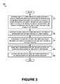
- FIG. 3is a flow chart illustrating a method, in accordance with an example embodiment.
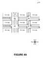
- FIG. 4Ashows an example map with blocks separated with north-south roads and east-west roads, in accordance with an example embodiment.
- FIG. 4Bshows a close-up view of an intersection of the example map shown in FIG. 4A , in accordance with an example embodiment.
- a computing devicecan be programmed to be a vehicle control system that operates a vehicle autonomously or without a human driver being required to direct the vehicle along a route from a start to a destination.
- the vehicle control systemcan generate and select driving behaviors on the way to the destination.
- Example driving behaviorsinclude one or a combination of: heading left/right, turning left/right, performing a U-turn, maintaining course and speed, increasing speed, decreasing speed, slowly moving forward, reversing direction, and stopping. Other driving behaviors are possible as well.
- the vehicle control systemmay be implemented in or may take the form of a vehicle, such as an automobile.
- vehicle control systemmay be implemented in or take the form of another vehicle, such as a truck, motorcycle, off-road vehicle, bus, boat, airplane, helicopter, lawn mower, recreational vehicle, amusement park vehicle, farm vehicle, construction vehicle, tram, golf cart, train, or trolley.
- Other vehiclescan possibly be controlled by vehicle control systems as well.
- the computing device acting as the vehicle control systemcan estimate the current state of the environment surrounding the vehicle based on a number of inputs.
- a collection of inputs to the computing device generating and selecting driving behaviorscan come from sensors on the vehicle.
- the sensorscan provide information about features in the vehicle's driving environment, such as other vehicles, traffic signals and signs, directional information, locations, speeds, and acceleration, fuel information, vehicle status information, roads, intersections, lane information, lane boundaries, speed limits, and other features.
- the mapcan include location information for features along a road such as traffic signs, signals, buildings, parking lots, parks/natural areas, additional information about building and other locations along the road, road geometry information, lane information, and other information.
- the mapcan include and/or be associated with visibility information for features at various places along a road. Visibility information for locations along the road can be generated, stored, and retrieved to aid navigation for the autonomous vehicle. This visibility information can be stored with the map and/or in data that is otherwise associated with the map, such as a database that can be queried with map coordinates, e.g., coordinates of an intersection, and return corresponding visibility information for the map coordinates. Once visibility information is calculated e.g., at a visibility calculation server, the visibility information can be stored and perhaps distributed to multiple autonomous vehicles. In some embodiments, the autonomous vehicle can query the visibility server for visibility information and/or maps during autonomous vehicle operation.
- Intersectionscan pose particular challenges for autonomous vehicle operation. Intersections can have traffic lights that are partially or completely occluded, or blocked from view, by other vehicles, trees, buildings and other objects. Competing features at intersections, such as a number of simultaneously visible traffic lights, traffic signs, and non-traffic lights and signs, can make differentiating traffic-control features from non-traffic-control features challenging. Also, to safely navigate an intersection, an autonomous vehicle may view both a current lane and lanes of one or more cross streets.
- the visibility informationcan indicate, for a given lane at an intersection, which lane(s) provides the best view(s) of feature(s) at the intersection.
- the autonomous vehiclecan query the map or associated data to get visibility information about an intersection, receive retrieved visibility information about the intersection, and use the retrieved visibility information to generate driving behavior(s), perhaps to improve viewing of feature(s) at the intersection.
- the visibility informationcan include visibility information that indicates visibility information at one or more sub-lane positions within a lane.
- the autonomous vehiclecan generate driving behaviors to change to the left lane when safely possible.
- the mapcan store a respective score for each valid position leading up to the intersection based on how well that position allows the vehicle to observe the features of the intersection.
- the scorecan be a combined score for a set of features at the intersection, or can include separate scores for each feature at the intersection.
- the autonomous vehiclecan simply query the map and/or associated data while navigating rather than needing to perform visibility calculations on-the-fly.
- computing resources that may have been used to calculate visibility information in real-timecan be saved by using stored visibility information. Further, these computing resources can be being saved while approaching and/or navigating through an intersection, likely to be a critical time of autonomous vehicle operation during which computing resources may be heavily loaded.
- FIG. 1is a simplified block diagram of an example vehicle 100 , in accordance with an example embodiment.
- Components coupled to or included in the vehicle 100may include a propulsion system 102 , a sensor system 104 , a control system 106 , peripherals 108 , a power supply 110 , a computing device 111 , and a user interface 112 .
- the computing device 111may include a processor 113 , and a memory 114 .
- the memory 114may include instructions 115 executable by the processor 113 , and may also store map data 116 .
- Components of the vehicle 100may be configured to work in an interconnected fashion with each other and/or with other components coupled to respective systems.
- the power supply 110may provide power to all the components of the vehicle 100 .
- the computing device 111may be configured to receive information from and control the propulsion system 102 , the sensor system 104 , the control system 106 , and the peripherals 108 .
- the computing device 111may be configured to generate a display of images on and receive inputs from the user interface 112 .
- Map data 116can include information for one or more roads and features along the roads.
- the road informationcan include locations that the road travels through, connecting roads, intersections, road names and/or numbers, road geometry information, road size (e.g., one lane, two lanes, etc.), lane information, and other information.
- Features along the roadcan include but are not limited to any combination of traffic signs, traffic signals, other signs and signals, buildings, parking lots, parks/natural areas, historical markers, amenities, points-of-interest, businesses, and additional information about locations along the road.
- Map data 116can include and/or be associated with visibility information 117 for features at various places along a road. Visibility information 117 can be generated, stored, and retrieved to aid navigation for the autonomous vehicle. Visibility information 117 can be stored with map data 116 , with data that is otherwise associated with the map, such as a database that can be queried with map coordinates for an intersection and return the corresponding visibility information for the intersection. Once visibility information is calculated e.g., at a visibility calculation server, the visibility information can be stored and distributed to multiple autonomous vehicles. In some embodiments, the autonomous vehicle can query the visibility server for visibility information and/or maps during autonomous vehicle operation.
- the vehicle 100may include more, fewer, or different systems, and each system may include more, fewer, or different components. Additionally, the systems and components shown may be combined or divided in any number of ways.
- the propulsion system 102may be configured to provide powered motion for the vehicle 100 .
- the propulsion system 102includes an engine/motor 118 , an energy source 120 , a transmission 122 , and wheels/tires 124 .
- the propulsion system 102may additionally or alternatively include components other than those shown.
- the engine/motor 118may be or include any combination of an internal combustion engine, an electric motor, a steam engine, and a Stirling engine. Other motors and engines are possible as well.
- the propulsion system 102could include multiple types of engines and/or motors.
- a gas-electric hybrid carcould include a gasoline engine and an electric motor. Other examples are possible.
- the energy source 120may be a source of energy that powers the engine/motor 118 in full or in part. That is, the engine/motor 118 may be configured to convert the energy source 120 into mechanical energy. Examples of energy sources 120 include gasoline, diesel, other petroleum-based fuels, propane, other compressed gas-based fuels, ethanol, solar panels, batteries, and other sources of electrical power. The energy source(s) 120 could additionally or alternatively include any combination of fuel tanks, batteries, capacitors, and/or flywheels. In some examples, the energy source 120 may provide energy for other systems of the vehicle 100 as well.
- the transmission 122may be configured to transmit mechanical power from the engine/motor 118 to the wheels/tires 124 .
- the transmission 122may include a gearbox, clutch, differential, drive shafts, and/or other elements.
- the drive shaftscould include one or more axles that are configured to be coupled to the wheels/tires 124 .
- the wheels/tires 124 of vehicle 100could be configured in various formats, including a unicycle, bicycle/motorcycle, tricycle, or car/truck four-wheel format. Other wheel/tire formats are possible as well, such as those including six or more wheels.
- the wheels/tires 124 of vehicle 100may be configured to rotate differentially with respect to other wheels/tires 124 .
- the wheels/tires 124may include at least one wheel that is fixedly attached to the transmission 122 and at least one tire coupled to a rim of the wheel that could make contact with the driving surface.
- the wheels/tires 124may include any combination of metal and rubber, or combination of other materials.
- the sensor system 104may include a number of sensors configured to sense information about an environment in which the vehicle 100 is located. As shown, the sensors of the sensor system include a Global Positioning System (GPS) module 126 , an inertial measurement unit (IMU) 128 , a RADAR unit 130 , a laser rangefinder and/or LIDAR unit 132 , a camera 134 , and actuators 136 configured to modify a position and/or orientation of the sensors.
- the sensor system 104may include additional sensors as well, including, for example, sensors that monitor internal systems of the vehicle 100 (e.g., an oxygen monitor, a fuel gauge, an engine oil temperature, etc.).
- the sensor system 104may additionally or alternatively include components other than those shown. Other sensors are possible as well
- the GPS module 126may be any sensor configured to estimate a geographic location of the vehicle 100 .
- the GPS module 126may include a transceiver configured to estimate a position of the vehicle 100 with respect to the Earth, based on satellite-based positioning data.
- the computing device 111may be configured to use the GPS module 126 in combination with the map data 116 to estimate a location of a lane boundary on road on which the vehicle 100 may be travelling on.
- the GPS module 126may take other forms as well.
- the IMU 128may be any combination of sensors configured to sense position and orientation changes of the vehicle 100 based on inertial acceleration.
- the combination of sensorsmay include, for example, accelerometers and gyroscopes. Other combinations of sensors are possible as well.
- the RADAR 130 unitmay be any sensor configured to sense objects in the environment in which the vehicle 100 is located using radio signals. In some examples, in addition to sensing the objects, the RADAR unit 130 may additionally be configured to sense the speed and/or direction of motion of the objects.
- the laser rangefinder or LIDAR unit 132may be any sensor configured to sense objects in the environment in which the vehicle 100 is located using lasers.
- the laser rangefinder or LIDAR unit 132may include a laser source and/or laser scanner configured to emit a laser and a detector configured to detect reflections of the laser.
- the laser rangefinder or LIDAR 132may be configured to operate in a coherent (e.g., using heterodyne detection) or an incoherent detection mode.
- the camera 134may be any camera (e.g., a still camera, a video camera, etc.) configured to capture images of the environment in which the vehicle 100 is located. To this end, the camera may take any of the forms described above.
- the control system 106may be configured to control operation of the vehicle 100 and its components. To this end, the control system 106 may include a steering unit 138 , a throttle 140 , a brake unit 142 , a sensor fusion algorithm 144 , a computer vision system 146 , a navigation or pathing system 148 , and an obstacle avoidance system 150 .
- the steering unit 138may be any combination of mechanisms configured to adjust the heading or direction of the vehicle 100 .
- the throttle 140may be any combination of mechanisms configured to control the operating speed and acceleration of the engine/motor 118 and, in turn, the speed and acceleration of the vehicle 100 .
- the brake unit 142may be any combination of mechanisms configured to decelerate the vehicle 100 .
- the brake unit 142may use friction to slow the wheels/tires 124 .
- the brake unit 142may be configured to be regenerative and convert the kinetic energy of the wheels/tires 124 to electric current.
- the brake unit 142may take other forms as well.
- the sensor fusion algorithm 144may include an algorithm (or a computer program product storing an algorithm) executable by the computing device 111 , for example.
- the sensor fusion algorithm 144may be configured to accept data from the sensor system 104 as an input.
- the datamay include, for example, data representing information sensed at the sensors of the sensor system 104 .
- the sensor fusion algorithm 144may include, for example, a Kalman filter, a Bayesian network, or another algorithm.
- the sensor fusion algorithm 144may further be configured to provide various assessments based on the data from the sensor system 104 , including, for example, evaluations of individual objects and/or features in the environment in which the vehicle 100 is located, evaluations of particular situations, and/or evaluations of possible impacts based on particular situations. Other assessments are possible as well
- the computer vision system 146may be any system configured to process and analyze images captured by the camera 134 in order to identify objects and/or features in the environment in which the vehicle 100 is located, including, for example, lane information, traffic signals and obstacles. To this end, the computer vision system 146 may use an object recognition algorithm, a Structure from Motion (SFM) algorithm, video tracking, or other computer vision techniques. In some examples, the computer vision system 146 may additionally be configured to map the environment, track objects, estimate the speed of objects, etc.
- SFMStructure from Motion
- the navigation and pathing system 148may be any system configured to determine a driving path for the vehicle 100 .
- the navigation and pathing system 148may additionally be configured to update the driving path dynamically while the vehicle 100 is in operation.
- the navigation and pathing system 148may be configured to incorporate data from the sensor fusion algorithm 144 , the GPS module 126 , and one or more predetermined maps so as to determine the driving path for the vehicle 100 .
- the obstacle avoidance system 150may be any system configured to identify, evaluate, and avoid or otherwise negotiate obstacles in the environment in which the vehicle 100 is located.
- the control system 106may additionally or alternatively include components other than those shown.
- Peripherals 108may be configured to allow the vehicle 100 to interact with external sensors, other vehicles, and/or a user.
- the peripherals 108may include, for example, a wireless communication system 152 , a touchscreen 154 , a microphone 156 , and/or a speaker 158 .
- the wireless communication system 152may be any system configured to be wirelessly coupled to one or more other vehicles, sensors, or other entities, either directly or via a communication network.
- the wireless communication system 152may include an antenna and a chipset for communicating with the other vehicles, sensors, or other entities either directly or over an air interface.
- the chipset or wireless communication system 152in general may be arranged to communicate according to one or more other types of wireless communication (e.g., protocols) such as Bluetooth, communication protocols described in IEEE 802.11 (including any IEEE 802.11 revisions), cellular technology (such as GSM, CDMA, UMTS, EV-DO, WiMAX, or LTE), Zigbee, dedicated short range communications (DSRC), and radio frequency identification (RFID) communications, among other possibilities.
- the wireless communication system 152may take other forms as well.
- the touchscreen 154may be used by a user to input commands to the vehicle 100 .
- the touchscreen 154may be configured to sense at least one of a position and a movement of a user's finger via capacitive sensing, resistance sensing, or a surface acoustic wave process, among other possibilities.
- the touchscreen 154may be capable of sensing finger movement in a direction parallel or planar to the touchscreen surface, in a direction normal to the touchscreen surface, or both, and may also be capable of sensing a level of pressure applied to the touchscreen surface.
- the touchscreen 154may be formed of one or more translucent or transparent insulating layers and one or more translucent or transparent conducting layers.
- the touchscreen 154may take other forms as well
- the microphone 156may be configured to receive audio (e.g., a voice command or other audio input) from a user of the vehicle 100 .
- the speakers 158may be configured to output audio to the user of the vehicle 100 .
- the peripherals 108may additionally or alternatively include components other than those shown.
- the power supply 110may be configured to provide power to some or all of the components of the vehicle 100 .
- the power supply 110may include, for example, a rechargeable lithium-ion or lead-acid battery.
- one or more banks of batteriescould be configured to provide electrical power.
- Other power supply materials and configurationsare possible as well.
- the power supply 110 and energy source 120may be implemented together, as in some all-electric cars.
- the processor 113 included in the computing device 111may comprise one or more general-purpose processors and/or one or more special-purpose processors. To the extent the processor 113 includes more than one processor; such processors could work separately or in combination.
- the computing device 111may be configured to control functions of the vehicle 100 based on input received through the user interface 112 , for example.
- the memory 114may comprise one or more volatile and/or one or more non-volatile storage components, such as optical, magnetic, and/or organic storage, and the memory 114 may be integrated in whole or in part with the processor 113 .
- the memory 114may contain the instructions 115 (e.g., program logic) executable by the processor 113 to execute various vehicle functions.
- the components of the vehicle 100could be configured to work in an interconnected fashion with other components within and/or outside their respective systems. To this end, the components and systems of the vehicle 100 may be communicatively linked together by a system bus, network, and/or other connection mechanism (not shown).
- one or more components or systemsmay be removably mounted on or otherwise connected (mechanically or electrically) to the vehicle 100 using wired or wireless connections.
- the vehicle 100may include one or more elements in addition to or instead of those shown.
- the vehicle 100may include one or more additional interfaces and/or power supplies.
- Other additional componentsare possible as well.
- the memory 114may further include instructions executable by the processor 113 to control and/or communicate with the additional components.
- FIG. 2illustrates an example vehicle 200 , in accordance with an embodiment.
- FIG. 2shows a Right Side View, Front View, Back View, and Top View of the vehicle 200 .
- vehicle 200is illustrated in FIG. 2 as an automobile, other examples are possible.
- the vehicle 200could represent a truck, motorcycle, off-road vehicle, bus, boat, airplane, helicopter, lawn mower, recreational vehicle, amusement park vehicle, farm vehicle, construction vehicle, tram, golf cart, train, trolley, or some other vehicle.
- the vehicle 200includes a first sensor unit 202 , a second sensor unit 204 , a third sensor unit 206 , a wireless communication system 208 , and a camera 210 .
- vehicle 200can include one or more other components in addition to or instead of those shown.
- Each of the first, second, and third sensor units 202 - 206may include any combination of global positioning system sensors, inertial measurement units, RADAR units, laser rangefinders, LIDAR units, cameras, lane detection sensors, and acoustic sensors. Other types of sensors are possible as well.
- first, second, and third sensor units 202are shown to be mounted in particular locations on the vehicle 200 , in some examples the sensor unit 202 may be mounted elsewhere on the vehicle 200 , either inside or outside the vehicle 200 . Further, while only three sensor units are shown, in some examples more or fewer sensor units may be included in the vehicle 200 .
- one or more of the first, second, and third sensor units 202 - 206may include one or more movable mounts on which the sensors may be movably mounted.
- the movable mountmay include, for example, a rotating platform. Sensors mounted on the rotating platform could be rotated so that the sensors may obtain information from each direction around the vehicle 200 .
- the movable mountmay include a tilting platform. Sensors mounted on the tilting platform could be tilted within a particular range of angles and/or azimuths so that the sensors may obtain information from a variety of angles.
- the movable mountmay take other forms as well.
- one or more of the first, second, and third sensor units 202 - 206may include one or more actuators configured to adjust the position and/or orientation of sensors in the sensor unit by moving the sensors and/or movable mounts.
- Example actuatorsinclude motors, pneumatic actuators, hydraulic pistons, relays, solenoids, and piezoelectric actuators. Other actuators are possible as well.
- the wireless communication system 208may be any system configured to wirelessly couple to one or more other vehicles, sensors, or other entities, either directly or via a communication network as described above with respect to the wireless communication system 152 in FIG. 1 . While the wireless communication system 208 is shown to be positioned on a roof of the vehicle 200 , in other examples the wireless communication system 208 could be located, fully or in part, elsewhere.
- the camera 210may be any camera (e.g., a still camera, a video camera, etc.) configured to capture images of the environment in which the vehicle 200 is located. To this end, the camera 210 may be configured to detect visible light, or may be configured to detect light from other portions of the spectrum, such as infrared or ultraviolet light, or x-rays. Other types of cameras are possible as well.
- the camera 210may be a two-dimensional detector, or may have a three-dimensional spatial range. In some examples, the camera 210 may be, for example, a range detector configured to generate a two-dimensional image indicating a distance from the camera 210 to a number of points in the environment. To this end, the camera 210 may use one or more range detecting techniques.
- the camera 210may use a structured light technique in which the vehicle 200 illuminates an object in the environment with a predetermined light pattern, such as a grid or checkerboard pattern and uses the camera 210 to detect a reflection of the predetermined light pattern off the object. Based on distortions in the reflected light pattern, the vehicle 200 may determine the distance to the points on the object.
- the predetermined light patternmay comprise infrared light, or light of another wavelength.
- the camera 210may use a laser scanning technique in which the vehicle 200 emits a laser and scans across a number of points on an object in the environment. While scanning the object, the vehicle 200 uses the camera 210 to detect a reflection of the laser off the object for each point. Based on a length of time it takes the laser to reflect off the object at each point, the vehicle 200 may determine the distance to the points on the object.
- the camera 210may use a time-of-flight technique in which the vehicle 200 emits a light pulse and uses the camera 210 to detect a reflection of the light pulse off an object at a number of points on the object.
- the camera 210may include a number of pixels, and each pixel may detect the reflection of the light pulse from a point on the object. Based on a length of time it takes the light pulse to reflect off the object at each point, the vehicle 200 may determine the distance to the points on the object.
- the light pulsemay be a laser pulse, for example.
- Other range detecting techniquesare possible as well, including stereo triangulation, sheet-of-light triangulation, interferometry, and coded aperture techniques, among others.
- the camera 210may take other forms as well.
- the camera 210may include a movable mount and/or an actuator configured to adjust the position and/or orientation of the camera 210 . While FIG. 2 shows camera 210 mounted inside a front windshield of the vehicle 200 , in other examples the camera 210 may be mounted elsewhere on the vehicle 200 , either inside or outside the vehicle 200 .
- a control system of the vehicle 200may be configured to control the vehicle 200 in accordance with a given driving behavior from among multiple possible driving behaviors.
- the control systemmay be configured to receive information from sensors coupled to the vehicle 200 (on or off the vehicle 200 ), select a driving behavior based on the information, and control the vehicle 200 in accordance with the selected driving behavior.
- the control systemfurther may be configured to continuously monitor the information received from the sensors to continuously evaluate driving conditions and also may be configured to modify the driving behavior or select another driving behavior based on changes in the driving conditions.
- FIG. 3is a flow chart illustrating an example method 300 .
- method 300begins at block 310 , where a map can be stored at a computing device associated with a vehicle.
- the vehiclecan be configured to operate in an autonomous operation mode that supports a plurality of driving behaviors.
- the mapcan include information about a plurality of roads, a plurality of features, and visibility information for at least a first feature in the plurality of features.
- the first positioncan be associated with an intersection of at least two roads in the plurality of roads. In other embodiments, the first position can be associated with a lane position on a road in the plurality of roads, where the lane position is associated with a lane of the road. In particular of these other embodiments, the first position can be associated with both the lane position and a sub-lane position within the lane of the road.
- the first featureis associated with a first traffic control device.
- the first traffic control deviceis further associated with a second feature, where the first feature includes a traffic light and the second feature includes a turn-control signal.
- the computing devicecan query the map for visibility information for the first feature at a first position.
- the visibility informationcan be stored with the map, while in other embodiments, the visibility information can be stored in data associated with the map, such as a visibility-information database configured to be queried based on map coordinates, or other reference(s) to the map.
- the visibility informationcan include a visibility index, perhaps a numerical visibility index.
- the first positioncan be associated with a plurality of sub-positions, and where the visibility index can include an ordering of best-to-worst sub-positions at the first location.
- querying the map for visibility information for the first featurecan include querying the map for visibility information for the first feature based on a time of day.
- the visibility information of the first feature at the first positioncan be based on an occluding object associated with the first feature.
- the computing devicecan, in response to querying the map, receive the visibility information for the first feature at the first position.
- the computing devicecan select a driving behavior for the vehicle based on the visibility information.
- Example driving behaviorsinclude but are not limited to, one or a combination of: heading left/right, turning left/right, performing a U-turn, maintaining course and speed, increasing speed, decreasing speed, slowly moving forward, reversing direction, and stopping.
- the computing devicecan control the vehicle in accordance with the selected driving behavior.
- FIG. 4Ashows an example map 400 with nine blocks 450 - 466 separated by north-south roads Main St. 414 and Oak St. 416 and east-west roads One Way St. 410 and Two-Way St. 412 .
- the north-south roads and east-west roadsmake four intersections 422 , 424 , 426 , and 428 .
- Intersection 422 between One-Way St. 410 and Main St. 414includes several traffic lights, shown with boxes surrounding the letter “L” on FIG. 4A .
- Intersections 424 , 426 , and 428respectively have three, two, and four stop signs for traffic control. Each stop sign is shown on FIG. 4A as an octagon surrounding the letter “S”.
- the autonomous vehiclecan use visibility information to position itself to observe key information at each intersection.
- visibility informationcan include data at various lane positions that indicates which lane position provides the best view of features at each intersection.
- These featurescan include but are not limited to any combination of traffic signs, traffic signals, other signs and signals, buildings, parking lots, parks/natural areas, historical markers, amenities, points-of-interest, businesses, and additional information about locations associated with the intersection. Other features are possible as well.
- This visibility informationcan be stored with the map and/or in data that is otherwise associated with the map, such as a database that can be queried with map coordinates for an intersection and return the corresponding visibility information for the intersection.
- the autonomous vehiclecan simply query the map and/or associate data while navigating rather than needing to perform visibility calculations on-the-fly to estimate the best lane position for visibility and perhaps whether or not a current lane position will suffice.
- FIG. 4Bshows a close-up view of intersection 422 of map 400 .
- Intersection 422is an intersection between One-way St. 410 and Main St. 414 , with five traffic lights 432 , 434 , 436 , 438 , and 440 .
- Light 434can be further sub-divided into two features: vertical traffic lights 434 a and right-turn signal 434 b .
- FIG. 4Bshows that Main St. 414 has 4 lanes: Southbound Lanes 1 and 2, and Northbound Lanes 1 and 2.
- a position within a lane of a roadcan be termed to be a lane position of the road.
- Main St.has four lane positions: Southbound Lane 1, Southbound Lane 2, Northbound Lane 1, and Northbound Lane 2.
- a lane positioncan be divided into sub-positions.
- FIG. 4Bshows various lane positions and sub-lane positions on the south side of intersection 422 .
- Lane Position (LP) 441.10shows a position in Northbound Lane 1 approximately 1/10 th of the way between the left-side lane marker (shown as a thick dark line on FIG. 4B ) and the right-side lane marker separating Northbound Lanes 1 and 2.
- LPs 441.50 and 441.90respectively show positions in Northbound Lane 1 approximately halfway and approximately 9/10 th of the way between the left-side and right-side lane markers.
- LPs 442.10, 442.50, and 442.90respectively show positions in Northbound Lane 2 approximately 1/10 th , halfway, and 9/10 th of the way between the left-side and right-side lane markers.
- Visibility informationcan be calculated for each feature visible at each lane position and sub-lane position.
- visible featuresinclude One-Way St. 410 , Main St. 414 , intersection 422 , lights 432 , 434 a , 434 b , 436 , 438 , 440 , trees 444 , 446 , 448 , and blocks 450 and 452 .
- Example visibility information for feature 434 b at lane positions 441.10-442.90is shown in Table 1 below.
- the visibility information shown in Table 1is expressed as a visibility index expressing a visibility value from 0 (cannot be seen) to 10 (wholly visible).
- the autonomous vehiclecan move into the most-visible lane on its approach to the intersection, if feasible based on traffic conditions, desired routing, and perhaps other criteria. Once the autonomous vehicle gets in the most-visible lane, the autonomous vehicle can get a more reliable estimate of key information, such as a state of the traffic light (e.g., red, green or yellow) and locations of other vehicles.
- a state of the traffic lighte.g., red, green or yellow
- FIG. 4Bshows that tree 448 can occlude a view of light 438 from lane positions 442.10 through 442.90.
- light 438may be partially visible between trees 446 and 448 .
- a visibility index at position 442.90 of feature light 438can be 0, with an indication of occlusion by trees 448 .
- the visibility index of light 438can be updated to be greater than zero and the indication of occlusion can be removed.
- the map and/or associated datamay store where in a particular lane (e.g., slightly to left or right) the vehicle should try to be in order to get better information regarding the intersection, etc.
- One possible implementationis to store a score associated with every possible (legal) position leading up to the intersection (in all lanes) based on how well that position allows the vehicle to observe the key features of the intersection.
- visibility informationcan be or include a binary indication of whether a feature F is visible or not visible at a particular location. In other embodiments, the visibility information can be stored as an ordered list of best-to-worst locations.
- visibility informationcan be stored for points along the road as well.
- the visibility informationcan be stored at distance-based intervals along the road e.g., every 200 yards, or 0.5 km, at points where the visibility changes a relatively-large amount such as going into and/or leaving a bend in a road, as features become visible along the road, and/or based on other criteria.
- a visibility calculationcan take several criteria into account: time of day, temporary road hazards (e.g., effects of road construction), occluding features such as nearby-vegetation and bright lights, road conditions, traffic patterns, weather-related conditions, and/or other criteria.
- a feature F4may be visible at a location L4 traveling in a direction D during daylight and nighttime hours, but F4 is not readily visible at L4 traveling in direction D from a time about one half hour before sunset until dusk, due to sensors being in direct sunlight at L4 looking in direction D at F4.
- the visibility informationcan indicate that visibility of F4 from L4 is relatively low during a time interval.
- Stored visibility informationmay include environmental lighting information, such as sunset/sunrise information, moon-phase information, etc.
- environmental lighting informationsuch as sunset/sunrise information, moon-phase information, etc.
- use of a sunset/sunrise tablecan determine that on Mar. 2, 2012 for L4 in “Mountain View, Calif.”, “dawn” is at 6:11 AM, “sunrise” is at 6:37 AM, “sunset” is at 6:04 PM, and “dusk” is at 6:30 PM. Then, based on the sunset/sunrise data, a visibility calculation can determine a not-visible interval for F4 at L4, in Mountain View, Calif., traveling in direction D from a time about one half hour before sunset, or about 5:34 PM, until dusk, or 3:1 PM.
- a feature F5 that is relatively far from a road R that is visible during the daymay not be visible while driving at night and using headlights.
- the visibility informationcan indicate that visibility of F5 from various locations along R is relatively low during night hours and is relatively high during day hours. If night or day hours are defined based on sunset and sunrise, then the visibility data can use the environmental lighting information to determine visibility time intervals for F5.
- F5has a visible time interval during day hours between 6:37 AM to 6:04 PM, and a not-visible time interval during night hours from 6:05 PM until 6:35 AM on Mar. 3, 2012, as sunrise in Mountain View, Calif. on Mar. 3, 2012 is at 6:36 AM.
- certain features along a truck routecan be occluded by large trucks that typically operate during business hours, but those same features are typically not occluded by vehicles operating along the truck route during non-business hours.
- time of day visibility informationcan further be based on typically traffic flows for that time of day.
- each block and/or communicationmay represent a processing of information and/or a transmission of information in accordance with example embodiments.
- Alternative embodimentsare included within the scope of these example embodiments.
- functions described as blocks, transmissions, communications, requests, responses, and/or messagesmay be executed out of order from that shown or discussed, including substantially concurrent or in reverse order, depending on the functionality involved.
- more or fewer blocks and/or functionsmay be used with any of the ladder diagrams, scenarios, and flow charts discussed herein, and these ladder diagrams, scenarios, and flow charts may be combined with one another, in part or in whole.
- a block that represents a processing of informationmay correspond to circuitry that can be configured to perform the specific logical functions of a herein-described method or technique.
- a block that represents a processing of informationmay correspond to a module, a segment, or a portion of program code (including related data).
- the program codemay include one or more instructions executable by a processor for implementing specific logical functions or actions in the method or technique.
- the program code and/or related datamay be stored on any type of computer readable medium such as a storage device including a disk or hard drive or other storage medium.
- the computer readable mediummay also include non-transitory computer readable media such as computer-readable media that stores data for short periods of time like register memory, processor cache, and random access memory (RAM).
- the computer readable mediamay also include non-transitory computer readable media that stores program code and/or data for longer periods of time, such as secondary or persistent long term storage, like read only memory (ROM), optical or magnetic disks, compact-disc read only memory (CD-ROM), for example.
- the computer readable mediamay also be any other volatile or non-volatile storage systems.
- a computer readable mediummay be considered a computer readable storage medium, for example, or a tangible storage device.
- a block that represents one or more information transmissionsmay correspond to information transmissions between software and/or hardware modules in the same physical device. However, other information transmissions may be between software modules and/or hardware modules in different physical devices.
Landscapes
- Engineering & Computer Science (AREA)
- Automation & Control Theory (AREA)
- Transportation (AREA)
- Mechanical Engineering (AREA)
- General Physics & Mathematics (AREA)
- Radar, Positioning & Navigation (AREA)
- Remote Sensing (AREA)
- Physics & Mathematics (AREA)
- Aviation & Aerospace Engineering (AREA)
- Traffic Control Systems (AREA)
- Business, Economics & Management (AREA)
- Health & Medical Sciences (AREA)
- Artificial Intelligence (AREA)
- Evolutionary Computation (AREA)
- Game Theory and Decision Science (AREA)
- Medical Informatics (AREA)
- Navigation (AREA)
Abstract
Description
| TABLE 1 | |||
| Lane Position | Visibility Index | ||
| (LP) | of | ||
| 441.10 | 9.9 | ||
| 441.50 | 9.8 | ||
| 441.90 | 9.5 | ||
| 442.10 | 9.4 | ||
| 442.50 | 9.3 | ||
| 442.90 | 9.0 | ||
Claims (19)
Priority Applications (7)
| Application Number | Priority Date | Filing Date | Title |
|---|---|---|---|
| US13/441,800US8712624B1 (en) | 2012-04-06 | 2012-04-06 | Positioning vehicles to improve quality of observations at intersections |
| US14/193,674US9280156B1 (en) | 2012-04-06 | 2014-02-28 | Positioning vehicles to improve quality of observations at intersections |
| US15/006,657US9910439B1 (en) | 2012-04-06 | 2016-01-26 | Positioning vehicles to improve quality of observations at intersections |
| US15/879,222US10782695B1 (en) | 2012-04-06 | 2018-01-24 | Positioning vehicles to improve quality of observations at intersections |
| US17/000,981US11300962B1 (en) | 2012-04-06 | 2020-08-24 | Positioning vehicles to improve quality of observations at intersections |
| US17/654,259US12153432B2 (en) | 2012-04-06 | 2022-03-10 | Positioning vehicles to improve quality of observations at intersections |
| US18/929,174US20250053172A1 (en) | 2012-04-06 | 2024-10-28 | Positioning Vehicles to Improve Quality of Observations at Intersections |
Applications Claiming Priority (1)
| Application Number | Priority Date | Filing Date | Title |
|---|---|---|---|
| US13/441,800US8712624B1 (en) | 2012-04-06 | 2012-04-06 | Positioning vehicles to improve quality of observations at intersections |
Related Child Applications (1)
| Application Number | Title | Priority Date | Filing Date |
|---|---|---|---|
| US14/193,674ContinuationUS9280156B1 (en) | 2012-04-06 | 2014-02-28 | Positioning vehicles to improve quality of observations at intersections |
Publications (1)
| Publication Number | Publication Date |
|---|---|
| US8712624B1true US8712624B1 (en) | 2014-04-29 |
Family
ID=50514315
Family Applications (7)
| Application Number | Title | Priority Date | Filing Date |
|---|---|---|---|
| US13/441,800ActiveUS8712624B1 (en) | 2012-04-06 | 2012-04-06 | Positioning vehicles to improve quality of observations at intersections |
| US14/193,674Active2032-07-16US9280156B1 (en) | 2012-04-06 | 2014-02-28 | Positioning vehicles to improve quality of observations at intersections |
| US15/006,657Active2032-07-22US9910439B1 (en) | 2012-04-06 | 2016-01-26 | Positioning vehicles to improve quality of observations at intersections |
| US15/879,222Active2033-02-17US10782695B1 (en) | 2012-04-06 | 2018-01-24 | Positioning vehicles to improve quality of observations at intersections |
| US17/000,981ActiveUS11300962B1 (en) | 2012-04-06 | 2020-08-24 | Positioning vehicles to improve quality of observations at intersections |
| US17/654,259Active2033-04-05US12153432B2 (en) | 2012-04-06 | 2022-03-10 | Positioning vehicles to improve quality of observations at intersections |
| US18/929,174PendingUS20250053172A1 (en) | 2012-04-06 | 2024-10-28 | Positioning Vehicles to Improve Quality of Observations at Intersections |
Family Applications After (6)
| Application Number | Title | Priority Date | Filing Date |
|---|---|---|---|
| US14/193,674Active2032-07-16US9280156B1 (en) | 2012-04-06 | 2014-02-28 | Positioning vehicles to improve quality of observations at intersections |
| US15/006,657Active2032-07-22US9910439B1 (en) | 2012-04-06 | 2016-01-26 | Positioning vehicles to improve quality of observations at intersections |
| US15/879,222Active2033-02-17US10782695B1 (en) | 2012-04-06 | 2018-01-24 | Positioning vehicles to improve quality of observations at intersections |
| US17/000,981ActiveUS11300962B1 (en) | 2012-04-06 | 2020-08-24 | Positioning vehicles to improve quality of observations at intersections |
| US17/654,259Active2033-04-05US12153432B2 (en) | 2012-04-06 | 2022-03-10 | Positioning vehicles to improve quality of observations at intersections |
| US18/929,174PendingUS20250053172A1 (en) | 2012-04-06 | 2024-10-28 | Positioning Vehicles to Improve Quality of Observations at Intersections |
Country Status (1)
| Country | Link |
|---|---|
| US (7) | US8712624B1 (en) |
Cited By (35)
| Publication number | Priority date | Publication date | Assignee | Title |
|---|---|---|---|---|
| US8838321B1 (en)* | 2012-11-15 | 2014-09-16 | Google Inc. | Modifying a vehicle state based on the presence of a special-purpose vehicle |
| US9092977B1 (en) | 2012-11-15 | 2015-07-28 | Google Inc. | Leveraging of behavior of vehicles to detect likely presence of an emergency vehicle |
| US20150316387A1 (en)* | 2014-04-30 | 2015-11-05 | Toyota Motor Engineering & Manufacturing North America, Inc. | Detailed map format for autonomous driving |
| US9280156B1 (en) | 2012-04-06 | 2016-03-08 | Google Inc. | Positioning vehicles to improve quality of observations at intersections |
| US20160144857A1 (en)* | 2014-11-26 | 2016-05-26 | Denso Corporation | Automatic driving system for automatically driven vehicle |
| EP3028914A1 (en)* | 2014-12-03 | 2016-06-08 | HERE Global B.V. | Method and apparatus for providing an operational configuration for an autonomous vehicle |
| WO2016094224A1 (en)* | 2014-12-09 | 2016-06-16 | Toyota Motor Engineering & Manufacturing North America, Inc. | Autonomous vehicle detection of and response to yield scenarios |
| US9511767B1 (en) | 2015-07-01 | 2016-12-06 | Toyota Motor Engineering & Manufacturing North America, Inc. | Autonomous vehicle action planning using behavior prediction |
| US20170057496A1 (en)* | 2015-08-25 | 2017-03-02 | Toyota Motor Engineering & Manufacturing North America, Inc. | Autonomous vehicle operation within a center turn lane |
| WO2017070127A1 (en)* | 2015-10-21 | 2017-04-27 | Google Inc. | Methods and systems for clearing sensor occlusions |
| US9701306B2 (en) | 2014-12-23 | 2017-07-11 | Toyota Motor Engineering & Manufacturing North America, Inc. | Risk mitigation for autonomous vehicles relative to turning objects |
| US20170356746A1 (en)* | 2016-06-14 | 2017-12-14 | nuTonomy Inc. | Route Planning for an Autonomous Vehicle |
| US9911330B2 (en)* | 2014-08-21 | 2018-03-06 | Nissan Motor Co., Ltd. | Driving assistance device and driving assistance method |
| US10005464B2 (en) | 2015-08-27 | 2018-06-26 | Toyota Motor Engineering & Manufacturing North America, Inc. | Autonomous vehicle operation at multi-stop intersections |
| US10013508B2 (en) | 2014-10-07 | 2018-07-03 | Toyota Motor Engineering & Manufacturing North America, Inc. | Joint probabilistic modeling and inference of intersection structure |
| US10118614B2 (en) | 2014-04-30 | 2018-11-06 | Toyota Motor Engineering & Manufacturing North America, Inc. | Detailed map format for autonomous driving |
| US10169678B1 (en) | 2017-12-21 | 2019-01-01 | Luminar Technologies, Inc. | Object identification and labeling tool for training autonomous vehicle controllers |
| US10168702B2 (en)* | 2014-08-25 | 2019-01-01 | Clarion Co., Ltd. | Autonomous driving control device |
| US10309792B2 (en) | 2016-06-14 | 2019-06-04 | nuTonomy Inc. | Route planning for an autonomous vehicle |
| WO2020180881A1 (en)* | 2019-03-07 | 2020-09-10 | Zoox, Inc. | State machine for traversing junctions |
| US10829116B2 (en) | 2016-07-01 | 2020-11-10 | nuTonomy Inc. | Affecting functions of a vehicle based on function-related information about its environment |
| US10909866B2 (en) | 2018-07-20 | 2021-02-02 | Cybernet Systems Corp. | Autonomous transportation system and methods |
| US11094197B2 (en) | 2019-02-26 | 2021-08-17 | Toyota Research Institute, Inc. | System and method for switching from a curbside lane to a lane-of-interest |
| US11106922B2 (en)* | 2019-02-26 | 2021-08-31 | Toyota Research Institute, Inc. | System and method for collecting data from lanes-of-interest |
| US20210303882A1 (en)* | 2020-03-28 | 2021-09-30 | Deka Products Limited Partnership | System and method for intersection management by an autonomous vehicle |
| US11156468B2 (en)* | 2016-11-26 | 2021-10-26 | Thinkware Corporation | Device, method, computer program, and computer-readable recording medium for route guidance |
| US11347241B2 (en)* | 2017-02-21 | 2022-05-31 | Nec Corporation | Control device, control method, and non-transitory program recording medium |
| US20220204032A1 (en)* | 2020-12-31 | 2022-06-30 | Waymo Llc | Traffic light viewsheds |
| US11427191B2 (en) | 2019-10-31 | 2022-08-30 | Zoox, Inc. | Obstacle avoidance action |
| US11480962B1 (en) | 2019-06-28 | 2022-10-25 | Zoox, Inc. | Dynamic lane expansion |
| US11532167B2 (en) | 2019-10-31 | 2022-12-20 | Zoox, Inc. | State machine for obstacle avoidance |
| EP4174611A1 (en) | 2021-10-18 | 2023-05-03 | Yandex Self Driving Group Llc | Mobile robot and a method for controlling the mobile robot |
| RU2800529C1 (en)* | 2021-10-18 | 2023-07-24 | Общество с ограниченной ответственностью "Яндекс Беспилотные Технологии" | Mobile robot and method for mobile robot control |
| US11920942B2 (en) | 2016-11-26 | 2024-03-05 | Thinkware Corporation | Device, method, computer program, and computer readable-recording medium for route guidance |
| US12013250B2 (en) | 2016-11-26 | 2024-06-18 | Thinkware Corporation | Apparatus, method, computer program, and computer readable recording medium for route guidance |
Families Citing this family (10)
| Publication number | Priority date | Publication date | Assignee | Title |
|---|---|---|---|---|
| JP6604577B2 (en)* | 2016-07-07 | 2019-11-13 | パナソニックIpマネジメント株式会社 | Driving support method, driving support apparatus, driving support system, automatic driving control apparatus, vehicle and program using the same |
| US10640121B2 (en) | 2017-04-28 | 2020-05-05 | International Business Machines Corporation | Vehicle control for reducing road wear |
| US10564638B1 (en) | 2017-07-07 | 2020-02-18 | Zoox, Inc. | Teleoperator situational awareness |
| US10606259B2 (en) | 2017-07-07 | 2020-03-31 | Zoox, Inc. | Interactions between vehicle and teleoperations system |
| US10386836B2 (en) | 2017-07-07 | 2019-08-20 | Zoox, Inc. | Interactions between vehicle and teleoperations system |
| US11334753B2 (en)* | 2018-04-30 | 2022-05-17 | Uatc, Llc | Traffic signal state classification for autonomous vehicles |
| EP3599141B1 (en)* | 2018-07-25 | 2022-12-14 | Continental Autonomous Mobility Germany GmbH | A multi hypothesis prediction device for a vehicle |
| KR102673300B1 (en)* | 2019-04-24 | 2024-06-11 | 현대자동차주식회사 | Apparatus and method for controlling driving of vehicle |
| WO2021025214A1 (en)* | 2019-08-08 | 2021-02-11 | 엘지전자 주식회사 | Route providing device and method for providing route by same |
| US12172638B2 (en) | 2021-07-19 | 2024-12-24 | Embark Trucks, Inc. | Dynamically modifiable map |
Citations (9)
| Publication number | Priority date | Publication date | Assignee | Title |
|---|---|---|---|---|
| US5963148A (en)* | 1995-03-23 | 1999-10-05 | Honda Giken Kogyo Kabushiki Kaisha | Road situation perceiving system |
| US6151539A (en)* | 1997-11-03 | 2000-11-21 | Volkswagen Ag | Autonomous vehicle arrangement and method for controlling an autonomous vehicle |
| US20070124072A1 (en)* | 2005-11-30 | 2007-05-31 | Aisin Aw Co., Ltd. | Route guidance systems, methods, and programs |
| US20080162027A1 (en)* | 2006-12-29 | 2008-07-03 | Robotic Research, Llc | Robotic driving system |
| US20090118909A1 (en)* | 2007-10-31 | 2009-05-07 | Valeo Vision | Process for detecting a phenomenon limiting the visibility for a motor vehicle |
| US20100004856A1 (en)* | 2006-06-21 | 2010-01-07 | Toyota Jidosha Kabushiki Kaisha | Positioning device |
| US20100106356A1 (en)* | 2008-10-24 | 2010-04-29 | The Gray Insurance Company | Control and systems for autonomously driven vehicles |
| US7979172B2 (en)* | 1997-10-22 | 2011-07-12 | Intelligent Technologies International, Inc. | Autonomous vehicle travel control systems and methods |
| US8031062B2 (en)* | 2008-01-04 | 2011-10-04 | Smith Alexander E | Method and apparatus to improve vehicle situational awareness at intersections |
Family Cites Families (7)
| Publication number | Priority date | Publication date | Assignee | Title |
|---|---|---|---|---|
| US5349533A (en)* | 1992-05-08 | 1994-09-20 | Lockheed Missiles & Space Company, Inc. | System and method for collision checking between solid objects and vectors |
| JP3412684B2 (en)* | 1999-03-01 | 2003-06-03 | アイシン・エィ・ダブリュ株式会社 | Navigation device and recording medium of the device |
| EP1751499B1 (en)* | 2004-06-03 | 2012-04-04 | Making Virtual Solid, L.L.C. | En-route navigation display method and apparatus using head-up display |
| JP4466238B2 (en)* | 2004-07-07 | 2010-05-26 | 株式会社デンソー | Vehicle navigation device |
| JP2007127419A (en)* | 2005-10-31 | 2007-05-24 | Aisin Aw Co Ltd | System and method for route guidance |
| US8364398B2 (en)* | 2009-08-28 | 2013-01-29 | Navteq B.V. | Method of operating a navigation system to provide route guidance |
| US8712624B1 (en) | 2012-04-06 | 2014-04-29 | Google Inc. | Positioning vehicles to improve quality of observations at intersections |
- 2012
- 2012-04-06USUS13/441,800patent/US8712624B1/enactiveActive
- 2014
- 2014-02-28USUS14/193,674patent/US9280156B1/enactiveActive
- 2016
- 2016-01-26USUS15/006,657patent/US9910439B1/enactiveActive
- 2018
- 2018-01-24USUS15/879,222patent/US10782695B1/enactiveActive
- 2020
- 2020-08-24USUS17/000,981patent/US11300962B1/enactiveActive
- 2022
- 2022-03-10USUS17/654,259patent/US12153432B2/enactiveActive
- 2024
- 2024-10-28USUS18/929,174patent/US20250053172A1/enactivePending
Patent Citations (9)
| Publication number | Priority date | Publication date | Assignee | Title |
|---|---|---|---|---|
| US5963148A (en)* | 1995-03-23 | 1999-10-05 | Honda Giken Kogyo Kabushiki Kaisha | Road situation perceiving system |
| US7979172B2 (en)* | 1997-10-22 | 2011-07-12 | Intelligent Technologies International, Inc. | Autonomous vehicle travel control systems and methods |
| US6151539A (en)* | 1997-11-03 | 2000-11-21 | Volkswagen Ag | Autonomous vehicle arrangement and method for controlling an autonomous vehicle |
| US20070124072A1 (en)* | 2005-11-30 | 2007-05-31 | Aisin Aw Co., Ltd. | Route guidance systems, methods, and programs |
| US20100004856A1 (en)* | 2006-06-21 | 2010-01-07 | Toyota Jidosha Kabushiki Kaisha | Positioning device |
| US20080162027A1 (en)* | 2006-12-29 | 2008-07-03 | Robotic Research, Llc | Robotic driving system |
| US20090118909A1 (en)* | 2007-10-31 | 2009-05-07 | Valeo Vision | Process for detecting a phenomenon limiting the visibility for a motor vehicle |
| US8031062B2 (en)* | 2008-01-04 | 2011-10-04 | Smith Alexander E | Method and apparatus to improve vehicle situational awareness at intersections |
| US20100106356A1 (en)* | 2008-10-24 | 2010-04-29 | The Gray Insurance Company | Control and systems for autonomously driven vehicles |
Cited By (68)
| Publication number | Priority date | Publication date | Assignee | Title |
|---|---|---|---|---|
| US12153432B2 (en) | 2012-04-06 | 2024-11-26 | Waymo Llc | Positioning vehicles to improve quality of observations at intersections |
| US11300962B1 (en) | 2012-04-06 | 2022-04-12 | Waymo Llc | Positioning vehicles to improve quality of observations at intersections |
| US10782695B1 (en)* | 2012-04-06 | 2020-09-22 | Waymo Llc | Positioning vehicles to improve quality of observations at intersections |
| US9910439B1 (en)* | 2012-04-06 | 2018-03-06 | Waymo Llc | Positioning vehicles to improve quality of observations at intersections |
| US9280156B1 (en) | 2012-04-06 | 2016-03-08 | Google Inc. | Positioning vehicles to improve quality of observations at intersections |
| US11718297B1 (en) | 2012-11-15 | 2023-08-08 | Waymo Llc | Modifying a vehicle state based on the presence of a special-purpose vehicle |
| US9937924B1 (en) | 2012-11-15 | 2018-04-10 | Waymo Llc | Modifying a vehicle state based on the presence of a special-purpose vehicle |
| US10427684B1 (en) | 2012-11-15 | 2019-10-01 | Waymo Llc | Modifying a vehicle state based on the presence of a special-purpose vehicle |
| US9213338B1 (en) | 2012-11-15 | 2015-12-15 | Google Inc. | Modifying a vehicle state based on the presence of a special-purpose vehicle |
| US9092977B1 (en) | 2012-11-15 | 2015-07-28 | Google Inc. | Leveraging of behavior of vehicles to detect likely presence of an emergency vehicle |
| US11008008B1 (en) | 2012-11-15 | 2021-05-18 | Waymo Llc | Modifying a vehicle state based on the presence of a special-purpose vehicle |
| US9694818B1 (en) | 2012-11-15 | 2017-07-04 | Waymo Llc | Modifying a vehicle state based on the presence of a special-purpose vehicle |
| US8838321B1 (en)* | 2012-11-15 | 2014-09-16 | Google Inc. | Modifying a vehicle state based on the presence of a special-purpose vehicle |
| US10118614B2 (en) | 2014-04-30 | 2018-11-06 | Toyota Motor Engineering & Manufacturing North America, Inc. | Detailed map format for autonomous driving |
| US20160282879A1 (en)* | 2014-04-30 | 2016-09-29 | Toyota Motor Engineering & Manufacturing North America, Inc. | Detailed map format for autonomous driving |
| US9921585B2 (en)* | 2014-04-30 | 2018-03-20 | Toyota Motor Engineering & Manufacturing North America, Inc. | Detailed map format for autonomous driving |
| US20150316387A1 (en)* | 2014-04-30 | 2015-11-05 | Toyota Motor Engineering & Manufacturing North America, Inc. | Detailed map format for autonomous driving |
| US9911330B2 (en)* | 2014-08-21 | 2018-03-06 | Nissan Motor Co., Ltd. | Driving assistance device and driving assistance method |
| US10168702B2 (en)* | 2014-08-25 | 2019-01-01 | Clarion Co., Ltd. | Autonomous driving control device |
| US10013508B2 (en) | 2014-10-07 | 2018-07-03 | Toyota Motor Engineering & Manufacturing North America, Inc. | Joint probabilistic modeling and inference of intersection structure |
| US10005458B2 (en)* | 2014-11-26 | 2018-06-26 | Denso Corporation | Automatic driving system for automatically driven vehicle |
| US10625734B2 (en) | 2014-11-26 | 2020-04-21 | Denso Corporation | Automatic driving system for automatically driven vehicle |
| US20160144857A1 (en)* | 2014-11-26 | 2016-05-26 | Denso Corporation | Automatic driving system for automatically driven vehicle |
| US9499175B2 (en) | 2014-12-03 | 2016-11-22 | Here Global B.V. | Method and apparatus for providing an operational configuration for an autonomous vehicle |
| EP3028914A1 (en)* | 2014-12-03 | 2016-06-08 | HERE Global B.V. | Method and apparatus for providing an operational configuration for an autonomous vehicle |
| US9534910B2 (en) | 2014-12-09 | 2017-01-03 | Toyota Motor Engineering & Manufacturing North America, Inc. | Autonomous vehicle detection of and response to yield scenarios |
| WO2016094224A1 (en)* | 2014-12-09 | 2016-06-16 | Toyota Motor Engineering & Manufacturing North America, Inc. | Autonomous vehicle detection of and response to yield scenarios |
| US9701306B2 (en) | 2014-12-23 | 2017-07-11 | Toyota Motor Engineering & Manufacturing North America, Inc. | Risk mitigation for autonomous vehicles relative to turning objects |
| US9511767B1 (en) | 2015-07-01 | 2016-12-06 | Toyota Motor Engineering & Manufacturing North America, Inc. | Autonomous vehicle action planning using behavior prediction |
| US9694813B2 (en)* | 2015-08-25 | 2017-07-04 | Toyota Motor Engineering & Manufacturing North America, Inc. | Autonomous vehicle operation within a center turn lane |
| US20170057496A1 (en)* | 2015-08-25 | 2017-03-02 | Toyota Motor Engineering & Manufacturing North America, Inc. | Autonomous vehicle operation within a center turn lane |
| US10005464B2 (en) | 2015-08-27 | 2018-06-26 | Toyota Motor Engineering & Manufacturing North America, Inc. | Autonomous vehicle operation at multi-stop intersections |
| US10267908B2 (en) | 2015-10-21 | 2019-04-23 | Waymo Llc | Methods and systems for clearing sensor occlusions |
| WO2017070127A1 (en)* | 2015-10-21 | 2017-04-27 | Google Inc. | Methods and systems for clearing sensor occlusions |
| US11249182B2 (en) | 2015-10-21 | 2022-02-15 | Waymo Llc | Methods and systems for clearing sensor occlusions |
| US10309792B2 (en) | 2016-06-14 | 2019-06-04 | nuTonomy Inc. | Route planning for an autonomous vehicle |
| US11092446B2 (en)* | 2016-06-14 | 2021-08-17 | Motional Ad Llc | Route planning for an autonomous vehicle |
| US20170356746A1 (en)* | 2016-06-14 | 2017-12-14 | nuTonomy Inc. | Route Planning for an Autonomous Vehicle |
| US11022449B2 (en) | 2016-06-14 | 2021-06-01 | Motional Ad Llc | Route planning for an autonomous vehicle |
| US11022450B2 (en) | 2016-06-14 | 2021-06-01 | Motional Ad Llc | Route planning for an autonomous vehicle |
| US10829116B2 (en) | 2016-07-01 | 2020-11-10 | nuTonomy Inc. | Affecting functions of a vehicle based on function-related information about its environment |
| US11156468B2 (en)* | 2016-11-26 | 2021-10-26 | Thinkware Corporation | Device, method, computer program, and computer-readable recording medium for route guidance |
| US11920942B2 (en) | 2016-11-26 | 2024-03-05 | Thinkware Corporation | Device, method, computer program, and computer readable-recording medium for route guidance |
| US12013250B2 (en) | 2016-11-26 | 2024-06-18 | Thinkware Corporation | Apparatus, method, computer program, and computer readable recording medium for route guidance |
| US12442651B2 (en) | 2016-11-26 | 2025-10-14 | Thinkware Corporation | Apparatus, method, computer program, and computer readable recording medium for route guidance |
| US12416507B2 (en) | 2016-11-26 | 2025-09-16 | Thinkware Corporation | Device, method, computer program, and computer readable-recording medium for route guidance |
| US11347241B2 (en)* | 2017-02-21 | 2022-05-31 | Nec Corporation | Control device, control method, and non-transitory program recording medium |
| US10169678B1 (en) | 2017-12-21 | 2019-01-01 | Luminar Technologies, Inc. | Object identification and labeling tool for training autonomous vehicle controllers |
| US10535191B2 (en) | 2017-12-21 | 2020-01-14 | Luminar Technologies, Inc. | Object identification and labeling tool for training autonomous vehicle controllers |
| US10275689B1 (en) | 2017-12-21 | 2019-04-30 | Luminar Technologies, Inc. | Object identification and labeling tool for training autonomous vehicle controllers |
| US10175697B1 (en)* | 2017-12-21 | 2019-01-08 | Luminar Technologies, Inc. | Object identification and labeling tool for training autonomous vehicle controllers |
| US10169680B1 (en) | 2017-12-21 | 2019-01-01 | Luminar Technologies, Inc. | Object identification and labeling tool for training autonomous vehicle controllers |
| US10909866B2 (en) | 2018-07-20 | 2021-02-02 | Cybernet Systems Corp. | Autonomous transportation system and methods |
| US11106922B2 (en)* | 2019-02-26 | 2021-08-31 | Toyota Research Institute, Inc. | System and method for collecting data from lanes-of-interest |
| US11094197B2 (en) | 2019-02-26 | 2021-08-17 | Toyota Research Institute, Inc. | System and method for switching from a curbside lane to a lane-of-interest |
| US11137766B2 (en) | 2019-03-07 | 2021-10-05 | Zoox, Inc. | State machine for traversing junctions |
| WO2020180881A1 (en)* | 2019-03-07 | 2020-09-10 | Zoox, Inc. | State machine for traversing junctions |
| US11480962B1 (en) | 2019-06-28 | 2022-10-25 | Zoox, Inc. | Dynamic lane expansion |
| US11532167B2 (en) | 2019-10-31 | 2022-12-20 | Zoox, Inc. | State machine for obstacle avoidance |
| US11427191B2 (en) | 2019-10-31 | 2022-08-30 | Zoox, Inc. | Obstacle avoidance action |
| US11927445B2 (en)* | 2020-03-28 | 2024-03-12 | Deka Products Limited Partnership | System and method for intersection management by an autonomous vehicle |
| US12276504B2 (en) | 2020-03-28 | 2025-04-15 | Deka Products Limited Partnership | System and method for intersection management by an autonomous vehicle |
| US20210303882A1 (en)* | 2020-03-28 | 2021-09-30 | Deka Products Limited Partnership | System and method for intersection management by an autonomous vehicle |
| US12005926B2 (en)* | 2020-12-31 | 2024-06-11 | Waymo Llc | Traffic light viewsheds |
| US20220204032A1 (en)* | 2020-12-31 | 2022-06-30 | Waymo Llc | Traffic light viewsheds |
| EP4174611A1 (en) | 2021-10-18 | 2023-05-03 | Yandex Self Driving Group Llc | Mobile robot and a method for controlling the mobile robot |
| RU2800529C1 (en)* | 2021-10-18 | 2023-07-24 | Общество с ограниченной ответственностью "Яндекс Беспилотные Технологии" | Mobile robot and method for mobile robot control |
| US12248325B2 (en) | 2021-10-18 | 2025-03-11 | Y.E. Hub Armenia LLC | Mobile robot and a method for controlling the mobile robot |
Also Published As
| Publication number | Publication date |
|---|---|
| US11300962B1 (en) | 2022-04-12 |
| US9910439B1 (en) | 2018-03-06 |
| US10782695B1 (en) | 2020-09-22 |
| US9280156B1 (en) | 2016-03-08 |
| US20220197290A1 (en) | 2022-06-23 |
| US20250053172A1 (en) | 2025-02-13 |
| US12153432B2 (en) | 2024-11-26 |
Similar Documents
| Publication | Publication Date | Title |
|---|---|---|
| US12153432B2 (en) | Positioning vehicles to improve quality of observations at intersections | |
| US12327415B2 (en) | Use of relationship between activities of different traffic signals in a network to improve traffic signal state estimation | |
| US12134384B2 (en) | Robust method for detecting traffic signals and their associated states | |
| US8527199B1 (en) | Automatic collection of quality control statistics for maps used in autonomous driving | |
| US9261879B2 (en) | Use of uncertainty regarding observations of traffic intersections to modify behavior of a vehicle | |
| US9355562B1 (en) | Using other vehicle trajectories to aid autonomous vehicles driving through partially known areas |
Legal Events
| Date | Code | Title | Description |
|---|---|---|---|
| AS | Assignment | Owner name:GOOGLE INC., CALIFORNIA Free format text:ASSIGNMENT OF ASSIGNORS INTEREST;ASSIGNORS:FERGUSON, DAVE;FAIRFIELD, NATHANIEL;TEMPLETON, BRADLEY;REEL/FRAME:028009/0211 Effective date:20120406 | |
| STCF | Information on status: patent grant | Free format text:PATENTED CASE | |
| AS | Assignment | Owner name:WAYMO HOLDING INC., CALIFORNIA Free format text:ASSIGNMENT OF ASSIGNORS INTEREST;ASSIGNOR:GOOGLE INC.;REEL/FRAME:042084/0741 Effective date:20170321 Owner name:WAYMO LLC, CALIFORNIA Free format text:ASSIGNMENT OF ASSIGNORS INTEREST;ASSIGNOR:WAYMO HOLDING INC.;REEL/FRAME:042085/0001 Effective date:20170322 | |
| AS | Assignment | Owner name:GOOGLE LLC, CALIFORNIA Free format text:CHANGE OF NAME;ASSIGNOR:GOOGLE INC.;REEL/FRAME:044142/0357 Effective date:20170929 | |
| MAFP | Maintenance fee payment | Free format text:PAYMENT OF MAINTENANCE FEE, 4TH YEAR, LARGE ENTITY (ORIGINAL EVENT CODE: M1551) Year of fee payment:4 | |
| AS | Assignment | Owner name:WAYMO LLC, CALIFORNIA Free format text:ASSIGNMENT OF ASSIGNORS INTEREST;ASSIGNOR:WAYMO HOLDING INC.;REEL/FRAME:047142/0817 Effective date:20170322 | |
| AS | Assignment | Owner name:GOOGLE LLC, CALIFORNIA Free format text:CORRECTIVE ASSIGNMENT TO CORRECT THE CORRECTIVE BY NULLIFICATIONTO CORRECT INCORRECTLY RECORDED APPLICATION NUMBERS PREVIOUSLY RECORDED ON REEL 044142 FRAME 0357. ASSIGNOR(S) HEREBY CONFIRMS THE CHANGE OF NAME;ASSIGNOR:GOOGLE INC.;REEL/FRAME:047837/0678 Effective date:20170929 | |
| AS | Assignment | Owner name:WAYMO LLC, CALIFORNIA Free format text:SUBMISSION TO CORRECT AN ERROR MADE IN A PREVIOUSLY RECORDED DOCUMENT THAT ERRONEOUSLY AFFECTS THE IDENTIFIED APPLICATIONS;ASSIGNOR:WAYMO LLC;REEL/FRAME:051093/0861 Effective date:20191001 | |
| MAFP | Maintenance fee payment | Free format text:PAYMENT OF MAINTENANCE FEE, 8TH YEAR, LARGE ENTITY (ORIGINAL EVENT CODE: M1552); ENTITY STATUS OF PATENT OWNER: LARGE ENTITY Year of fee payment:8 |