US8712536B2 - Eye therapy system - Google Patents
Eye therapy systemDownload PDFInfo
- Publication number
- US8712536B2 US8712536B2US12/753,523US75352310AUS8712536B2US 8712536 B2US8712536 B2US 8712536B2US 75352310 AUS75352310 AUS 75352310AUS 8712536 B2US8712536 B2US 8712536B2
- Authority
- US
- United States
- Prior art keywords
- segments
- distal end
- eye
- energy
- conductor
- Prior art date
- Legal status (The legal status is an assumption and is not a legal conclusion. Google has not performed a legal analysis and makes no representation as to the accuracy of the status listed.)
- Expired - Fee Related, expires
Links
- 238000002560therapeutic procedureMethods0.000title1
- 239000004020conductorSubstances0.000claimsabstractdescription193
- 210000004087corneaAnatomy0.000claimsdescription116
- 238000000034methodMethods0.000claimsdescription21
- 230000035515penetrationEffects0.000claimsdescription16
- 238000010438heat treatmentMethods0.000claimsdescription10
- 239000003989dielectric materialSubstances0.000claimsdescription8
- 230000008878couplingEffects0.000claimsdescription7
- 238000010168coupling processMethods0.000claimsdescription7
- 238000005859coupling reactionMethods0.000claimsdescription7
- 230000001419dependent effectEffects0.000claims2
- 239000000463materialSubstances0.000description9
- 102000008186CollagenHuman genes0.000description8
- 108010035532CollagenProteins0.000description8
- 229920001436collagenPolymers0.000description8
- 239000000560biocompatible materialSubstances0.000description7
- 229910052751metalInorganic materials0.000description6
- 239000002184metalSubstances0.000description6
- 230000008901benefitEffects0.000description5
- 230000008859changeEffects0.000description5
- 238000012545processingMethods0.000description5
- 230000003213activating effectEffects0.000description4
- 230000000694effectsEffects0.000description4
- 150000002739metalsChemical class0.000description4
- 208000001491myopiaDiseases0.000description4
- 230000004379myopiaEffects0.000description4
- 210000001519tissueAnatomy0.000description4
- 238000006243chemical reactionMethods0.000description3
- 208000037265diseases, disorders, signs and symptomsDiseases0.000description3
- 230000003902lesionEffects0.000description3
- 239000000615nonconductorSubstances0.000description3
- 238000001356surgical procedureMethods0.000description3
- 238000011282treatmentMethods0.000description3
- 229910001369BrassInorganic materials0.000description2
- RYGMFSIKBFXOCR-UHFFFAOYSA-NCopperChemical compound[Cu]RYGMFSIKBFXOCR-UHFFFAOYSA-N0.000description2
- 206010020675HypermetropiaDiseases0.000description2
- 201000002287KeratoconusDiseases0.000description2
- 230000002159abnormal effectEffects0.000description2
- 229910052782aluminiumInorganic materials0.000description2
- XAGFODPZIPBFFR-UHFFFAOYSA-NaluminiumChemical compound[Al]XAGFODPZIPBFFR-UHFFFAOYSA-N0.000description2
- 238000013459approachMethods0.000description2
- 201000009310astigmatismDiseases0.000description2
- 239000010951brassSubstances0.000description2
- 229910052802copperInorganic materials0.000description2
- 239000010949copperSubstances0.000description2
- 238000006073displacement reactionMethods0.000description2
- 230000004438eyesightEffects0.000description2
- 230000006870functionEffects0.000description2
- 201000006318hyperopiaDiseases0.000description2
- 230000004305hyperopiaEffects0.000description2
- 230000007246mechanismEffects0.000description2
- 229910001092metal group alloyInorganic materials0.000description2
- 230000003287optical effectEffects0.000description2
- 239000004033plasticSubstances0.000description2
- 229920003023plasticPolymers0.000description2
- 230000008569processEffects0.000description2
- 230000005855radiationEffects0.000description2
- 210000001525retinaAnatomy0.000description2
- 238000007493shaping processMethods0.000description2
- 239000010935stainless steelSubstances0.000description2
- 229910001220stainless steelInorganic materials0.000description2
- 239000002470thermal conductorSubstances0.000description2
- 208000003556Dry Eye SyndromesDiseases0.000description1
- 206010013774Dry eyeDiseases0.000description1
- 239000004642PolyimideSubstances0.000description1
- 229920006362Teflon®Polymers0.000description1
- 238000003491arrayMethods0.000description1
- 238000004590computer programMethods0.000description1
- 239000002826coolantSubstances0.000description1
- 238000001816coolingMethods0.000description1
- 210000003683corneal stromaAnatomy0.000description1
- 230000007423decreaseEffects0.000description1
- 230000008021depositionEffects0.000description1
- 238000013461designMethods0.000description1
- 238000011161developmentMethods0.000description1
- 238000009792diffusion processMethods0.000description1
- 229920001746electroactive polymerPolymers0.000description1
- 230000003511endothelial effectEffects0.000description1
- 210000000981epitheliumAnatomy0.000description1
- 238000011156evaluationMethods0.000description1
- 208000030533eye diseaseDiseases0.000description1
- 239000000835fiberSubstances0.000description1
- 238000005290field theoryMethods0.000description1
- 230000005484gravityEffects0.000description1
- 230000035876healingEffects0.000description1
- 238000011065in-situ storageMethods0.000description1
- 238000012977invasive surgical procedureMethods0.000description1
- 238000012986modificationMethods0.000description1
- 230000004048modificationEffects0.000description1
- 210000005036nerveAnatomy0.000description1
- 229920001721polyimidePolymers0.000description1
- 229920002635polyurethanePolymers0.000description1
- 239000004814polyurethaneSubstances0.000description1
- 238000002360preparation methodMethods0.000description1
- 230000000135prohibitive effectEffects0.000description1
- 238000013515scriptMethods0.000description1
- 229920000260silasticPolymers0.000description1
- 230000002277temperature effectEffects0.000description1
Images


Classifications
- A—HUMAN NECESSITIES
- A61—MEDICAL OR VETERINARY SCIENCE; HYGIENE
- A61B—DIAGNOSIS; SURGERY; IDENTIFICATION
- A61B18/00—Surgical instruments, devices or methods for transferring non-mechanical forms of energy to or from the body
- A61B18/18—Surgical instruments, devices or methods for transferring non-mechanical forms of energy to or from the body by applying electromagnetic radiation, e.g. microwaves
- A61B18/1815—Surgical instruments, devices or methods for transferring non-mechanical forms of energy to or from the body by applying electromagnetic radiation, e.g. microwaves using microwaves
- A—HUMAN NECESSITIES
- A61—MEDICAL OR VETERINARY SCIENCE; HYGIENE
- A61F—FILTERS IMPLANTABLE INTO BLOOD VESSELS; PROSTHESES; DEVICES PROVIDING PATENCY TO, OR PREVENTING COLLAPSING OF, TUBULAR STRUCTURES OF THE BODY, e.g. STENTS; ORTHOPAEDIC, NURSING OR CONTRACEPTIVE DEVICES; FOMENTATION; TREATMENT OR PROTECTION OF EYES OR EARS; BANDAGES, DRESSINGS OR ABSORBENT PADS; FIRST-AID KITS
- A61F9/00—Methods or devices for treatment of the eyes; Devices for putting in contact-lenses; Devices to correct squinting; Apparatus to guide the blind; Protective devices for the eyes, carried on the body or in the hand
- A61F9/007—Methods or devices for eye surgery
- A61F9/008—Methods or devices for eye surgery using laser
- A61F2009/00861—Methods or devices for eye surgery using laser adapted for treatment at a particular location
- A61F2009/00872—Cornea
- A—HUMAN NECESSITIES
- A61—MEDICAL OR VETERINARY SCIENCE; HYGIENE
- A61F—FILTERS IMPLANTABLE INTO BLOOD VESSELS; PROSTHESES; DEVICES PROVIDING PATENCY TO, OR PREVENTING COLLAPSING OF, TUBULAR STRUCTURES OF THE BODY, e.g. STENTS; ORTHOPAEDIC, NURSING OR CONTRACEPTIVE DEVICES; FOMENTATION; TREATMENT OR PROTECTION OF EYES OR EARS; BANDAGES, DRESSINGS OR ABSORBENT PADS; FIRST-AID KITS
- A61F9/00—Methods or devices for treatment of the eyes; Devices for putting in contact-lenses; Devices to correct squinting; Apparatus to guide the blind; Protective devices for the eyes, carried on the body or in the hand
- A61F9/007—Methods or devices for eye surgery
- A61F9/0079—Methods or devices for eye surgery using non-laser electromagnetic radiation, e.g. non-coherent light or microwaves
- A—HUMAN NECESSITIES
- A61—MEDICAL OR VETERINARY SCIENCE; HYGIENE
- A61F—FILTERS IMPLANTABLE INTO BLOOD VESSELS; PROSTHESES; DEVICES PROVIDING PATENCY TO, OR PREVENTING COLLAPSING OF, TUBULAR STRUCTURES OF THE BODY, e.g. STENTS; ORTHOPAEDIC, NURSING OR CONTRACEPTIVE DEVICES; FOMENTATION; TREATMENT OR PROTECTION OF EYES OR EARS; BANDAGES, DRESSINGS OR ABSORBENT PADS; FIRST-AID KITS
- A61F9/00—Methods or devices for treatment of the eyes; Devices for putting in contact-lenses; Devices to correct squinting; Apparatus to guide the blind; Protective devices for the eyes, carried on the body or in the hand
- A61F9/007—Methods or devices for eye surgery
- A61F9/013—Instruments for compensation of ocular refraction ; Instruments for use in cornea removal, for reshaping or performing incisions in the cornea
- A—HUMAN NECESSITIES
- A61—MEDICAL OR VETERINARY SCIENCE; HYGIENE
- A61N—ELECTROTHERAPY; MAGNETOTHERAPY; RADIATION THERAPY; ULTRASOUND THERAPY
- A61N1/00—Electrotherapy; Circuits therefor
- A61N1/40—Applying electric fields by inductive or capacitive coupling ; Applying radio-frequency signals
- A61N1/403—Applying electric fields by inductive or capacitive coupling ; Applying radio-frequency signals for thermotherapy, e.g. hyperthermia
Definitions
- the inventionpertains to the field of keratoplasty and, more particularly, to a system configured to achieve adjustable contact with an eye to apply thermokeratoplasty.
- a variety of eye disorderssuch as myopia, keratoconus, and hyperopia, involve abnormal shaping of the cornea. Keratoplasty reshapes the cornea to correct such disorders. For example, with myopia, the shape of the cornea causes the refractive power of an eye to be too great and images to be focused in front of the retina. Flattening aspects of the cornea's shape through keratoplasty decreases the refractive power of an eye with myopia and causes the image to be properly focused at the retina.
- Invasive surgical proceduressuch as laser-assisted in-situ keratomileusis (LASIK) may be employed to reshape the cornea.
- LASIKlaser-assisted in-situ keratomileusis
- Such surgical procedurestypically require a healing period after surgery.
- such surgical proceduresmay involve complications, such as dry eye syndrome caused by the severing of corneal nerves.
- Thermokeratoplastyis a noninvasive procedure that may be used to correct the vision of persons who have disorders associated with abnormal shaping of the cornea, such as myopia, keratoconus, and hyperopia.
- Thermokeratoplastymay be performed by applying electrical energy, for example, in the microwave band or radio frequency (RF) band.
- microwave thermokeratoplastymay employ a near field microwave applicator to apply energy to the cornea and raise the corneal temperature. At about 60° C., the collagen fibers in the cornea shrink. The onset of shrinkage is rapid, and stresses resulting from this shrinkage reshape the corneal surface.
- application of heat energy according to particular patternsincluding, but not limited to, circular or annular patterns, may cause aspects of the cornea to flatten and improve vision in the eye.
- the pattern of energy applied to a cornea during thermokeratoplastydepends on how the energy applicator is applied against the cornea.
- Embodiments according to aspects of the present inventionaccount for the shape of the cornea when the applicator is positioned to deliver energy and can be selectively configured to apply energy to the cornea according to a selected pattern and/or penetration depth.
- An electrical energy applicatorin one embodiment extends from a proximal end to a distal end.
- the energy conducting applicatorincludes, at the proximal end, a connection to one or more electrical energy sources.
- the energy conducting applicatordirects electrical energy from the one or more electrical energy sources to the distal end.
- the distal endis positionable at a surface of an eye.
- the energy conducting applicatorincludes an outer conductor and an inner conductor extending to the distal end.
- the outer conductor and the inner conductorare separated by a gap.
- the outer conductorincludes a plurality of moveable outer segments and the inner conductor includes a plurality of moveable inner segments.
- the plurality of outer segments and the plurality of inner segmentsform a total contact surface at the distal end.
- the total contact surfaceis positionable at a surface of an eye.
- the electrical energyis applied to the eye according to the total contact surface.
- the total contact surface area of the electrical energy applicatoris positioned at a surface of an eye, and electrical energy is applied through the electrical energy conducting applicator to the eye according to the total contact surface.
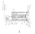
- FIG. 1illustrates a system for applying heat to a cornea of an eye to cause reshaping of the cornea.
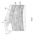
- FIG. 2Aillustrates a high resolution image of a cornea after heat has been applied.
- FIG. 2Billustrates another high resolution image of the cornea of FIG. 2A .
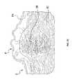
- FIG. 2Cillustrates a histology image of the cornea of FIG. 2A .
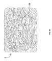
- FIG. 2Dillustrates another histology image of the cornea of FIG. 2A .
- FIG. 3Aillustrates a view of a system that achieves adjustable contact between the energy conducting element and the eye according to aspects of the present invention.
- FIG. 3Billustrates a view of the energy conducting element of the system of FIG. 3A .
- FIG. 3Cillustrates another view of the energy conducting element of the system of FIG. 3A .
- FIG. 4Aillustrates a view of an energy conducting element according further aspects of the present invention.
- FIG. 4Billustrates a view of an energy conducting element according to still further aspects of the present invention.
- FIG. 4Cillustrates a view of an energy conducting element according to still further aspects of the present invention.
- FIG. 4Dillustrates a view of an energy conducting element according to still further aspects of the present invention.
- an energy conducting element of the applicatorincludes a plurality of movable segments that can adjust to the shape of the cornea.
- the plurality of movable segmentstherefore defines a total contact surface that corresponds to the shape of the cornea and provides the desired contact for the delivery of energy.
- the plurality of movable segmentscan also be selectively configured to apply energy to the cornea according to a selected pattern and/or penetration depth.
- FIG. 1illustrates an example system for applying energy to a cornea 2 of an eye 1 to generate heat and cause reshaping of the cornea.
- FIG. 1shows an applicator 110 with an electrical energy conducting element 111 that is operably connected to an electrical energy source 120 , for example, via conventional conducting cables.
- the electrical energy conducting element 111extends from a proximal end 110 A to a distal end 110 B of the applicator 110 .
- the electrical energy conducting element 111conducts electrical energy from the source 120 to the distal end 110 B to apply heat energy to the cornea 2 , which is positioned at the distal end 110 B.
- the electrical energy source 120may include a microwave oscillator for generating microwave energy.
- the oscillatormay operate at a microwave frequency range of about 400 MHz to about 3000 MHz, and more specifically at a frequency of around 915 MHz or around 2450 MHz, which has been safely used in other applications.
- microwavemay generally correspond to a frequency range from about 10 MHz to about 10 GHz.
- the electrical energy conducting element 111may include two microwave conductors 111 A and 111 B, which extend from the proximal end 110 A to the distal end 110 B of the applicator 110 .
- the conductor 111 Amay be a substantially cylindrical outer conductor
- the conductor 111 Bmay be a substantially cylindrical inner conductor that extends through an inner passage extending through the conductor 111 A.
- the outer conductors 111 A and the inner conductors 111 Bmay be formed, for example, of aluminum, stainless steel, brass, copper, other metals, coated metals, metal-coated plastic, metal alloys, combinations thereof, or any other suitable conductive material.
- FIG. 1shows that the inner conductor 111 B may be recessed within the outer conductor 111 A to partially accommodate the shape of the cornea 2 .
- a substantially annular gap 111 C of a selected distanceis defined between the conductors 111 A and 111 B.
- the annular gap 111 Cextends from the proximal end 110 A to the distal end 110 B.
- a dielectric material 111 Dmay be used in portions of the annular gap 111 C to separate the conductors 111 A and 111 B.
- the distance of the annular gap 111 C between conductors 111 A and 111 Bdetermines, in part, the penetration depth of microwave energy into the cornea 2 according to established microwave field theory.
- the energy conducting element 111receives, at the proximal end 110 A, the electrical energy generated by the electrical energy source 120 , and directs microwave energy to the distal end 110 B, where the cornea 2 is positioned.
- the outer diameter of the inner conductor 111 Bmay be selected to achieve an appropriate change in corneal shape, i.e. keratometry, induced by the exposure to microwave energy.
- the inner diameter of the outer conductor 111 Amay be selected to achieve a desired gap between the conductors 111 A and 111 B.
- the outer diameter of the inner conductor 111 Branges from about 2 mm to about 10 mm while the inner diameter of the outer conductor 111 A ranges from about 2.1 mm to about 12 mm.
- the annular gap 111 Cmay be sufficiently small, e.g., in a range of about 0.1 mm to about 2.0 mm, to minimize exposure of the endothelial layer of the cornea (posterior surface) to elevated temperatures during the application of energy by the applicator 110 .
- a controller 140may be employed to selectively apply the energy in the form of heat any number of times according to any predetermined or calculated sequence.
- the heatmay be applied for any length of time.
- the magnitude of heat being applied to the corneamay also be varied. Adjusting such parameters for the application of heat determines the extent of changes that are brought about within the cornea 2 .
- the systemattempts to limit the changes in the cornea 2 to an appropriate amount of shrinkage of collagen fibrils in a selected region and according to a selected pattern.
- the microwave energymay be applied with low power (e.g., of the order of 40 W) and in long pulse lengths (e.g., of the order of one second).
- microwave energymay be applied in short pulses.
- the microwave energymay be applied in pulses having a higher power in the range of about 500 W to about 3 kW and a pulse duration in the range of about 5 milliseconds to about one second.
- each of the conductors 111 A and 111 Bmay be coated or covered with an electrical insulator to minimize the concentration of electrical current in the area of contact between the corneal surface (epithelium) 2 A and the conductors 111 A and 111 B.
- the conductors 111 A and 111 B, or at least a portion thereof,may be coated or covered with a material that can function both as an electrical insulator as well as a thermal conductor.
- a dielectric layer 110 Dis disposed along the distal end 111 B of the applicator 110 to protect the cornea 2 from electrical conduction current that would otherwise flow into the cornea 2 via conductors 111 A and 111 B. Such current flow may cause unwanted temperature effects in the cornea 2 and interfere with achieving a maximum temperature within the collagen fibrils in a mid-depth region 2 B of the cornea 2 . Accordingly, the dielectric layer 110 D is positioned between the conductors 111 A and 111 B and the cornea 2 . The dielectric layer 110 D may be sufficiently thin to minimize interference with microwave emissions and thick enough to prevent superficial deposition of electrical energy by flow of conduction current.
- the dielectric layer 110 Dmay be a biocompatible material deposited to a thickness of about 20-100 micrometers, preferably about 50 micrometers.
- the dielectric layer 110 Dcan be a flexible sheath-like structure of biocompatible material that covers the conductors 111 A and 111 B at the distal end 110 B and extends over a portion of the exterior wall of the outer conductor 111 B.
- the dielectric layer 110 Dcan include a first flexible sheath-like structure of biocompatible material that covers the distal end of the inner conductor 111 A and a second flexible sheath-like structure of biocompatible material that covers the distal end of the outer conductor 111 B.
- an interposing layersuch as the dielectric layer 110 D, may be employed between the conductors 111 A and 111 B and the cornea 2 as long as the interposing layer does not substantially interfere with the strength and penetration of the microwave radiation field in the cornea 2 and does not prevent sufficient penetration of the microwave field and generation of a desired heating pattern in the cornea 2 .
- the dielectric materialmay be elastic (e.g., polyurethane, silastic, combinations thereof and/or the like) or nonelastic (e.g., Teflon®, polyimides, combinations thereof and/or the like).
- the dielectric materialmay have a fixed dielectric constant or varying dielectric constant by mixing materials or doping the sheet, the variable dielectric being spatially distributed so that it may affect the microwave hearing pattern in a customized way.
- the thermal conductivity of the materialmay have fixed thermal properties (e.g., thermal conductivity and/or specific heat), or may also vary spatially, through mixing of materials or doping, and thus provide a means to alter the heating pattern in a prescribed manner.
- Another approach for spatially changing the heating patternis to make the dielectric sheet material of variable thickness. The thicker region will heat less than the thinner region and provides a further means of spatial distribution of microwave heating.
- the distal end 110 B of the applicator 110 as shown in FIG. 1is positioned on or near the corneal surface 2 A.
- the applicator 110makes direct contact with the corneal surface 2 A.
- such direct contactpositions the conductors 111 A and 111 B at the corneal surface 2 A (or substantially near the corneal surface 2 A if there is a thin interposing layer between the conductors 111 A and 111 B and the corneal surface 2 A). Accordingly, direct contact helps ensure that the pattern of microwave heating in the corneal tissue has substantially the same shape and dimension as the gap 111 C between the two microwave conductors 111 A and 111 B.
- FIG. 1The system of FIG. 1 is provided for illustrative purposes only, and other systems may be employed to apply heat to cause reshaping of the cornea.
- Other systemsare described, for example, in U.S. patent application Ser. No. 12/208,963, filed Sep. 11, 2008, which is a continuation-in-part application of U.S. patent application Ser. No. 11/898,189, filed on Sep. 10, 2007, the contents of these applications being entirely incorporated herein by reference.
- a cooling systemmay also be employed in combination with the applicator 110 to apply coolant to the cornea 2 and determine how the energy is applied to the cornea 2 .
- FIGS. 2A-Dillustrate an example of the effect of applying heat to corneal tissue with a system for applying heat, such as the system illustrated in FIG. 1 .
- FIGS. 2A and 2Billustrate high resolution images of cornea 2 after heat has been applied.
- a lesion 4extends from the corneal surface 2 A to a mid-depth region 2 B in the corneal stroma 2 C.
- the lesion 4is the result of changes in corneal structure induced by the application of heat as described above. These changes in structure result in an overall reshaping of the cornea 2 . It is noted that the application of heat, however, has not resulted in heat-related damage to the corneal tissue.
- the energy conducting element 111includes a contact surface 111 G at the distal end 110 B of the outer conductor 111 A and a contact surface 111 H at the distal end 110 B of the inner conductor 111 B.
- the contact surfaces 111 G and 111 H, or portions thereof,come into direct contact with the corneal surface 2 A.
- the pattern of energy applied to the cornea 2depends in part on the position of the contact surfaces 111 G and 111 H relative to the corneal surface 2 A.
- the contact surfaces 111 G and 111 Hare shown to be contoured in FIG. 1 , but it is understood that the contact surfaces 111 G and 111 H may have other predetermined shapes.
- the contact surfaces 111 G and 111 Hmay be designed to have a contoured shape, this predetermined shape may not correspond sufficiently to the actual shape of the corneal surface 2 A. Moreover, the contact surfaces 111 G and 111 H may be formed as integral surfaces from a rigid material, so that they cannot be dynamically changed to correspond more closely to the actual shape of the corneal surface 2 A. In general, the cost of providing a customized applicator, such as the applicator 110 in FIG. 1 , for each individual application may be prohibitive, so the contact surface 111 G and 111 H may be designed to approximate the general shape of the corneal surface 2 A as best as possible and to offer the broadest possible use.
- the contact surfaces 111 G and 111 Hmay each be a single surface shaped according to a symmetric concave model of the cornea 2 . Because the actual shapes of corneal surfaces 2 A may vary according to different individuals, however, the contact surfaces 111 G and 111 H may not provide the desired contact between the energy conducting element 111 and the corneal surface 2 A. In some cases, individuals may have asymmetric corneas 2 which are likely to experience non-uniform contact when symmetric contact surfaces 111 G and 111 H are applied. Non-uniform contact may result in imprecise and inaccurate delivery of energy to the cornea 2 and may prevent the desired reshaping of the cornea 2 .
- the energy conducting element 111is applied to the corneal surface 2 A to cause an observable amount of flattening, or applanation, of the cornea 2 .
- applanationmay provide a good indication that contact between the contact surfaces 111 G and 111 H and the corneal surface 2 A has been achieved
- pressure applied by the contact surfaces 111 G and 111 Hmay be non-uniform over the contact surfaces 111 G and 111 H if the shape of the contact surfaces 111 G and 111 H does not correspond sufficiently with the corneal surface 2 A.
- the application of non-uniform pressure against the corneal surface 2 Amay produce mechanical deformation that may affect the results of thermokeratoplasty.
- an energy conducting element of the applicatorincludes a plurality of movable segments that can adjust to the shape of the cornea when positioned against the cornea.
- the plurality of movable segmentsdefines a total contact surface that corresponds to the shape of the cornea and provides the desired contact for the delivery of energy.
- the ability to adjust the shape of the total contact surfacedynamically allows a single applicator design to be employed on varying corneal shapes.
- the segments 212 A and 212 Bmay extend along the longitudinal axis 210 C from an intermediate section 210 D of the energy conducting element 211 to the distal end 210 B.
- the outer conductor segments 212 Amay be organized within a region bounded by dashed lines A, which might generally correspond with the exterior walls of the outer conductor 111 A of FIG. 1 .
- the inner conductor segments 212 Bmay be organized within a region bounded by dashed line B, which might generally correspond with the exterior walls of the inner conductor 111 B of FIG. 1 .
- the segments 212 A and 212 Bmay be formed as cylindrical or pin-like structures from electrically conducting materials.
- aspects of the conductors 211 A and 211 Bmay be formed, for example, from aluminum, stainless steel, brass, copper, other metals, coated metals, metal-coated plastic, other metal alloys, combinations thereof or any other suitable conductive material. Although a specific number of segments 212 A and 212 B may be illustrated, it is contemplated that any number of segments 212 A and 212 B may be employed as long as the configuration provides the appropriate conducting characteristics for delivering energy to the cornea 2 .
- Each of the segments 212 Aincludes a segment contact surface 212 C
- each of the segments 212 Bincludes a segment contact surface 212 D.
- the segment contact surfaces 212 Cdefine a total contact surface 211 G for the outer conductor 211 A
- the segment contact surfaces 212 Ddefine a total contact surface 211 H for the inner conductor 211 B.
- the conductors 211 A and 211 Bmay be coated with or covered by a material that can function both as an electrical insulator as well as a thermal conductor.
- the materialmay be a dielectric layer employed along the distal end 210 B of the applicator 210 to protect the cornea 2 from electrical conduction current that would otherwise flow into the cornea 2 via conductors 211 A and 211 B.
- the dielectric layermay be employed between the conductors 211 A and 211 B and the cornea 2 as long as the interposing layer does not substantially interfere with the strength and penetration of the microwave radiation field in the cornea 2 and does not prevent sufficient penetration of the microwave field and generation of a desired heating pattern in the cornea 2 .
- the dielectric layercan be a flexible sheath-like structure of biocompatible material that covers the conductors 211 A and 211 B at the distal end 210 B and extends over a portion of the exterior wall of the outer conductor 211 B.
- the dielectric layercan include a first flexible sheath-like structure of biocompatible material that covers the distal end of the inner conductor 211 A and a second flexible sheath-like structure of biocompatible material that covers the distal end of the outer conductor 211 B.
- the dielectric layercan be formed as a plurality of sheath-like structures that are individually positioned over the outer surface of each of the conductor segments 212 A and 212 B.
- the segments 212 A and 212 Bmay be spaced apart from each other. However, the proximity of the segments 212 A allows the segments 212 A collectively to act as a single outer conductor, and the proximity of the segments 212 B allows the segments 212 B collectively to act as a single inner conductor.
- the segments 212 Amay be arranged so that the effect of delivering energy through one segment 212 A extends across the spaces to adjacent segments 212 A, and the segments 212 B are arranged so that the effect of delivering energy through one segment 212 B extends across the spaces to adjacent segments 212 B.
- the combination of the outer conductor 211 A and the inner conductor 211 Bdelivers energy from an energy source 220 to a distal end 210 B.
- the energyis delivered to the cornea 2 in a pattern that depends, in part, on a gap 211 C at the distal end 210 B defined between the outer conductor 211 A and the inner conductor 211 B.
- the energy conducting element 211may be applied to the eye 1 in a manner similar to the energy conducting element 111 to generate heat and cause reshaping of the cornea 2 .
- each outer conductor segment 212 Acan move along the longitudinal axis 210 C, relative to each of the other outer conductor segments 212 A.
- each inner conductor segment 212 Bcan move along the longitudinal axis 210 C, relative to each of the other inner conductor segments 212 B.
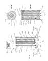
- the segments 212 A and 212 Bare movable to define different shapes for total contact surfaces 211 G and 211 H, respectively. As shown in FIG. 3A , the segments 212 A and 212 B may be moved so that the total contact surfaces 211 G and 211 H fit the actual shape of the corneal surface 2 A more closely.
- FIGS. 3A and 3Cshow that the applicator 210 may employ biasing devices 211 K and 211 L that provide a slight bias in the +x direction against corresponding segments 212 A and 212 B.
- the biasing devices 211 K and 211 Lmay be springs or a material with spring-like characteristics.
- the biasing devices 211 K and 211 Lmay additionally or alternatively be employed to provide a force in the +x direction.
- the biasing devices 211 K and 211 Lensure that the segments 212 A and 212 B remain in contact with the corneal surface 2 A without creating an undesired level of pressure against the corneal surface 2 A that may affect the thermokeratoplasty.
- the inner conductor segments 212 Bmay be recessed within the outer conductor segments 212 A (i.e., the inner conductor segments 212 B may be shorter than the outer conductor segments 212 A) or the biasing devices 211 K and 211 L may be configured such that the biasing force applied to the outer segments 212 A is greater than the biasing force applied to the inner segments 212 B.
- the biasing devices 211 K and 211 Lmay be employed in combination with the couplings 211 I and 211 J, respectively, where they can act on the ends of the corresponding segments 212 A and 212 B.
- the applicator 210can also include one or more devices for determining whether sufficient contact has been established between the applicator 210 (i.e., the individual conductor segments 212 A and 212 B) and the eye for accurate and precise delivery of energy to the eye.
- the applicator 210i.e., the individual conductor segments 212 A and 212 B
- Such devicesare described in U.S. application Ser. No. 12/617,544, filed Nov. 12, 2009, the contents of which being entirely incorporated herein by reference.
- the energy conducting element 211is moved in the +x direction to position each of the segments 212 A and 212 B against the corneal surface 2 A.
- some segments 212 A and 212 Bmay come into contact with the corneal surface 2 A, while the other segments 212 A and 212 B require further movement of the energy conducting element 211 in the +x direction to reach the corneal surface 2 A.
- the inner conductor segments 212 Bmay reach the corneal surface 2 A before the outer conductor segments 212 A, because the central region of the cornea 2 extends farther from the rest of the eye 1 and toward the oncoming energy conducting element 211 .
- the corneal surface 2 Aapplies a reaction force against the segments 212 A and 212 B already in contact.
- This reaction forcecauses the corresponding segments 212 A and 212 B to move in the ⁇ x direction, i.e., opposite to the other segments 212 A that are not in contact with the corneal surface 2 A and that are still moving toward the corneal surface 2 A.
- the reaction force in the ⁇ x directionis able to overcome the bias and cause movement of the segments 212 A and 212 B.
- this biaspromotes contact between the corneal surface 2 A and the segments 212 A and 212 B, but does not apply undesired levels of pressure as the segments 212 A and 212 B move against the bias.
- the energy conducting element 211is moved until all the segments 212 A and 212 B are in contact with the corneal surface 2 A.
- the relative movement between the segments 212 A and 212 Ballows the total contact surfaces 211 G and 211 H to change according to the shape of the corneal surface 2 A.
- the relative movementallows the contact and pressure applied by the energy conducting element 211 to be more uniform.
- aspects of the present inventionprovide a self-adjusting applicator that promotes desired contact with more uniform pressure. Once the appropriate contact has been achieved between the total contact surfaces 211 G and 211 H and the corneal surface 2 A, energy can be delivered, via the conductors 211 A and 211 B, to the cornea 2 in the desired reshaping pattern.
- the segments 212 Aextend from the distal end 210 B to the intermediate section 210 D of the outer conductor 211 A where they may be electrically connected by a coupling 211 I.
- the segments 212 Bextend from the distal end 210 B to the intermediate section 210 D of the inner conductor 211 B where they may be electrically connected by a coupling 211 J.
- the couplings 211 I and 211 Jmay be formed of a conductive material, such as those described previously, and facilitate the delivery of energy from the energy source 220 to the segments 212 A and 212 B, respectively.
- the segments 212 A and 212 Bmay, for example, slide within openings in the corresponding couplings 211 I and 211 J while remaining in conductive contact with the couplings 211 I and 211 J.
- 211 I or 2121 Jmay be flexible and may bend as the segments 212 A or 212 B slide up or down.
- the penetration depth of the energy into the cornea 2is determined, in part, by the distance of the gap 211 C between the outer conductor 211 A and the inner conductor 211 B. If, for example, the inner row of segments 212 A of the outer conductor 211 A is raised and no longer makes direct contact with the cornea surface 2 A, only the outer ring of segments 212 A of the outer conductor 211 A will be in contact with the cornea surface 2 A and the gap 211 C will be widened between the inner conductor 211 B and outer conductor 211 A at or near the cornea surface 2 A.
- the distance of the gap 211 Ccan be controlled by selectively raising one or more of the inner rows of the outer conductor segments 212 A and/or one or more of the outer rows of the inner conductor segments 212 B.
- FIGS. 3A-3Cillustrate the outer conductor 211 A having two rows of outer conductor segments 212 A and the inner conductor 211 B having six rows of inner conductor segments 212 B
- any other number of rows of outer conductor segments 212 A or inner conductor segments 212 Bcan be provided.
- the pattern of energy applied to the cornea 2is determined, in part, by the contact surfaces 211 G and 211 H at or near the cornea surface 2 A.
- various effective contact surface 211 G and 211 H configurationscan be achieved.
- the heating patternwill be based on a ring shaped inner conductor. If a smaller ring of conductor segments 212 B is left in contact with the cornea surface 2 A due to the elevation of the remaining conductor segments 212 B, the heating zone will be a smaller ring.
- the heating zonewill be biased away from the noncontact region.
- non-annular energy patternswhich may be formed by the conductor segments 212 A and 212 B are described in U.S. patent application Ser. No. 12/113,672, filed on May 1, 2008, the contents of which is entirely incorporated herein by reference.
- each conductor segment 212 A and 212 Bcan be coupled to an actuator device in addition to or instead of the biasing devices described above.
- the actuator devicescan be any devices capable of moving conductor segments 212 A and 212 B in the ⁇ x and/or +x direction along the longitudinal axis 210 C.
- suitable actuator devicesinclude electrical motors, pneumatic actuators, hydraulic pistons, relays, electroactive polymers, combinations thereof, and/or any other transducer device.
- the actuator devicescan be further coupled to a controller for providing automated control of the elevation of the segments 212 A and 212 B relative to the cornea surface 2 A.
- a locking mechanismcan be employed to ensure that the segments 212 A and 212 B are locked at a specific elevation relative to the cornea surface 2 A after the actuator device has moved the segments 212 A and 212 B into the appropriate position.
- a particular configuration of the conductor segments 212 A and 212 Bcan be achieved by first moving all segments 212 A and 212 B into contact with the cornea surface 2 A to achieve uniform pressure as described above and then raising specific segments 212 A and 212 B to one or more elevations above the cornea surface 2 A.
- a particular configuration of conductor segments 212 A and 212 Bcan be achieved by first moving specific segments 212 A and 212 B to one or more raised positions and then moving the remaining segments 212 A and 212 B into contact with the cornea surface 2 A to achieve uniform pressure over the remaining segments 212 A and 212 B.
- a system having multiple outer conductor segments 212 A and inner conductor segments 212 Balso advantageously allows for selective application of energy through the individual segments 212 A and/or 212 B to the cornea 2 .
- energycan be applied to the cornea 2 by some segments 212 A and 212 B but not other segments 212 A and 212 B.
- the depth of penetrationcan be selectively configured by activating or deactivating conductor segments 212 A and 212 B to achieve a selected distance for the gap 211 C.
- a pattern of energy applied to the corneacan be selectively configured by activating or deactivating the individual segments 212 A and 212 B.
- each of the segments 212 A and 212 Bis individually coupled to the energy source 220 .
- electrical energy from the energy source 220can be conducted from the proximal end 210 A to the distal end 210 B via the outer conductor segments 212 A and inner conductor segments 212 B that are activated.
- a controllercan be employed to select and activate the conductor segments 212 A and 212 B.
- a dielectric materialmay be disposed between neighbor (i.e., adjacent) segments to prevent or inhibit conduction of electrical current between the conductors 212 A and 212 B.
- the dielectric materialmay be formed as a part of sheath-like structures positioned over the outer surface of the conductors 212 A-B.
- each conductor segment 212 A and/or 212 Bcan be activated/deactivated when positioned in an elevated position relative to the cornea surface 2 A, or when positioned in contact with the cornea surface 2 A.
- the depth of penetration and/or the pattern of energy applied to the corneacan be controlled by selectively configuring the elevation of the conductor segments 212 A and 212 B and/or selectively activating or deactivating the conductor segments 212 A and 212 B.
- the applicator 210provides a single convenient and versatile tool that allows an operator to apply energy to the cornea according to different patterns and different penetration depths to suit different treatment cases, without requiring multiple applicators or interchangeable components.
- the applicator 210may be employed for a single application of energy according to a single outer conductor/inner conductor pair, the applicator 210 may be particularly advantageous when multiple applications of energy according to multiple patterns are required to achieve the desired change in the shape of the cornea. For example, energy is incrementally applied to the cornea in precise and measured steps in multiple ring-shaped patterns.
- An example of a multi-step approachis described in U.S. patent application Ser. No. 61/098,489, filed on Sep.
- energymay be applied multiple times according to different patterns and pulses, i.e., duration and magnitude, to achieve the desired shape change.
- an asymmetric shape changefor example to treat astigmatism, may be effected by multiple applications of energy in different ring-shaped patterns that are centered at different areas of the cornea.
- the conductor segments 212 A and 212 B illustrated in FIGS. 3A-3Cwere formed as cylindrical or pin-like structures, it is contemplated that in other embodiments, the segments can have any suitable shape or size.
- the conductors 311 A-B, 411 A-B, 511 B and 611 Bmay include segments that are formed as discrete sectors or sections of a cylinder. It is further contemplated that in some embodiments, the segments may include a combination of different shapes and sizes.
- controller(s) described abovemay be a programmable processing device that executes software, or stored instructions, and that may be operably connected to the other devices described above.
- physical processors and/or machines employed by embodiments of the present invention for any processing or evaluationmay include one or more networked or non-networked general purpose computer systems, microprocessors, field programmable gate arrays (FPGAs), digital signal processors (DSPs), micro-controllers, and the like, programmed according to the teachings of the exemplary embodiments of the present invention, as is appreciated by those skilled in the computer and software arts.
- the physical processors and/or machinesmay be externally networked with the image capture device, or may be integrated to reside within the image capture device.
- Computer code devices of the exemplary embodiments of the present inventionscan include any suitable interpretable or executable code mechanism, including but not limited to scripts, interpretable programs, dynamic link libraries (DLLs), Java classes and applets, complete executable programs, and the like. Moreover, parts of the processing of the exemplary embodiments of the present inventions can be distributed for better performance, reliability, cost, and the like.
- interpretable or executable code mechanismincluding but not limited to scripts, interpretable programs, dynamic link libraries (DLLs), Java classes and applets, complete executable programs, and the like.
- Computer-readable mediamay include, for example, a floppy disk, a flexible disk, hard disk, magnetic tape, any other suitable magnetic medium, a CD-ROM, CDRW, DVD, any other suitable optical medium, punch cards, paper tape, optical mark sheets, any other suitable physical medium with patterns of holes or other optically recognizable indicia, a RAM, a PROM, an EPROM, a FLASH-EPROM, any other suitable memory chip or cartridge, a carrier wave or any other suitable medium from which a computer can read.
- a floppy diska flexible disk, hard disk, magnetic tape, any other suitable magnetic medium, a CD-ROM, CDRW, DVD, any other suitable optical medium, punch cards, paper tape, optical mark sheets, any other suitable physical medium with patterns of holes or other optically recognizable indicia, a RAM, a PROM, an EPROM, a FLASH-EPROM, any other suitable memory chip or cartridge, a carrier wave or any other suitable medium from which a computer can read.
Landscapes
- Health & Medical Sciences (AREA)
- Surgery (AREA)
- Life Sciences & Earth Sciences (AREA)
- Biomedical Technology (AREA)
- Medical Informatics (AREA)
- Nuclear Medicine, Radiotherapy & Molecular Imaging (AREA)
- Electromagnetism (AREA)
- Engineering & Computer Science (AREA)
- Physics & Mathematics (AREA)
- Heart & Thoracic Surgery (AREA)
- Otolaryngology (AREA)
- Molecular Biology (AREA)
- Animal Behavior & Ethology (AREA)
- General Health & Medical Sciences (AREA)
- Public Health (AREA)
- Veterinary Medicine (AREA)
- Surgical Instruments (AREA)
Abstract
Description
Claims (33)
Priority Applications (1)
| Application Number | Priority Date | Filing Date | Title |
|---|---|---|---|
| US12/753,523US8712536B2 (en) | 2009-04-02 | 2010-04-02 | Eye therapy system |
Applications Claiming Priority (2)
| Application Number | Priority Date | Filing Date | Title |
|---|---|---|---|
| US16600209P | 2009-04-02 | 2009-04-02 | |
| US12/753,523US8712536B2 (en) | 2009-04-02 | 2010-04-02 | Eye therapy system |
Publications (2)
| Publication Number | Publication Date |
|---|---|
| US20100256705A1 US20100256705A1 (en) | 2010-10-07 |
| US8712536B2true US8712536B2 (en) | 2014-04-29 |
Family
ID=42826846
Family Applications (1)
| Application Number | Title | Priority Date | Filing Date |
|---|---|---|---|
| US12/753,523Expired - Fee RelatedUS8712536B2 (en) | 2009-04-02 | 2010-04-02 | Eye therapy system |
Country Status (2)
| Country | Link |
|---|---|
| US (1) | US8712536B2 (en) |
| WO (1) | WO2010115121A1 (en) |
Cited By (5)
| Publication number | Priority date | Publication date | Assignee | Title |
|---|---|---|---|---|
| US10575986B2 (en) | 2012-03-29 | 2020-03-03 | Cxl Ophthalmics, Llc | Ophthalmic treatment solution delivery devices and delivery augmentation methods |
| US10729716B2 (en) | 2012-03-29 | 2020-08-04 | Cxl Ophthalmics, Llc | Compositions and methods for treating or preventing diseases associated with oxidative stress |
| US10932864B2 (en) | 2018-11-28 | 2021-03-02 | Rxsight, Inc. | Tracking-based illumination control system |
| US11013593B2 (en) | 2018-12-02 | 2021-05-25 | Rxsight, Inc. | Light adjustable lens tracking system and method |
| US11033429B2 (en) | 2010-09-30 | 2021-06-15 | Cxl Ophthalmics, Llc | Ophthalmic treatment device, system, and method of use |
Families Citing this family (4)
| Publication number | Priority date | Publication date | Assignee | Title |
|---|---|---|---|---|
| US8992516B2 (en) | 2007-07-19 | 2015-03-31 | Avedro, Inc. | Eye therapy system |
| US8202272B2 (en) | 2007-07-19 | 2012-06-19 | Avedro, Inc. | Eye therapy system |
| JP2012508087A (en)* | 2008-11-11 | 2012-04-05 | アヴェドロ・インコーポレーテッド | Eye treatment system |
| EP2413832A1 (en)* | 2009-04-02 | 2012-02-08 | Avedro, INC. | Eye therapy system |
Citations (154)
| Publication number | Priority date | Publication date | Assignee | Title |
|---|---|---|---|---|
| US3073310A (en) | 1957-08-05 | 1963-01-15 | Zenon R Mocarski | Surgical instrument positioning device |
| US3776230A (en) | 1973-04-18 | 1973-12-04 | C Neefe | Method of rapidly reshaping the cornea to eliminate refractive errors |
| US4043342A (en) | 1974-08-28 | 1977-08-23 | Valleylab, Inc. | Electrosurgical devices having sesquipolar electrode structures incorporated therein |
| US4326529A (en) | 1978-05-26 | 1982-04-27 | The United States Of America As Represented By The United States Department Of Energy | Corneal-shaping electrode |
| US4381007A (en) | 1981-04-30 | 1983-04-26 | The United States Of America As Represented By The United States Department Of Energy | Multipolar corneal-shaping electrode with flexible removable skirt |
| US4429960A (en) | 1980-10-31 | 1984-02-07 | Mocilac Joseph P | Keratometric device |
| US4481948A (en) | 1980-12-29 | 1984-11-13 | Sole Gary M | Medical instrument, and methods of constructing and utilizing same |
| US4490022A (en) | 1982-01-04 | 1984-12-25 | Reynolds Alvin E | Apparatus for corneal corrective techniques |
| US4546773A (en) | 1981-01-23 | 1985-10-15 | Accutome, Inc. | Apparatus to measure conical thickness |
| US4712543A (en) | 1982-01-20 | 1987-12-15 | Baron Neville A | Process for recurving the cornea of an eye |
| US4743725A (en) | 1985-12-05 | 1988-05-10 | Skandinavisk Torkteknik Ab | Coaxial line microwave heating applicator with asymmetrical radiation pattern |
| US4796623A (en) | 1987-07-20 | 1989-01-10 | The Cooper Companies, Inc. | Corneal vacuum trephine system |
| US4805616A (en) | 1980-12-08 | 1989-02-21 | Pao David S C | Bipolar probes for ophthalmic surgery and methods of performing anterior capsulotomy |
| US4881543A (en) | 1988-06-28 | 1989-11-21 | Massachusetts Institute Of Technology | Combined microwave heating and surface cooling of the cornea |
| US4891043A (en) | 1987-05-28 | 1990-01-02 | Board Of Trustees Of The University Of Illinois | System for selective release of liposome encapsulated material via laser radiation |
| US4943296A (en) | 1986-03-28 | 1990-07-24 | Life Technology Research Foundation | Robot for surgical operation |
| US4994058A (en) | 1986-03-19 | 1991-02-19 | Summit Technology, Inc. | Surface shaping using lasers |
| US5019074A (en) | 1987-03-09 | 1991-05-28 | Summit Technology, Inc. | Laser reprofiling system employing an erodable mask |
| US5080660A (en) | 1990-05-11 | 1992-01-14 | Applied Urology, Inc. | Electrosurgical electrode |
| US5103005A (en) | 1989-07-21 | 1992-04-07 | Coors Biotech, Inc. | Method for recovery of riboflavin |
| US5123422A (en)* | 1988-04-08 | 1992-06-23 | Societe Anonyme Mxm | Electrode-carrier devices able to be implanted in the cochlea so as to electrically stimulate the nervus acusticus |
| US5171254A (en) | 1991-11-19 | 1992-12-15 | Sher Neal A | Eye fixation device |
| US5281211A (en) | 1989-06-07 | 1994-01-25 | University Of Miami, School Of Medicine, Dept. Of Ophthalmology | Noncontact laser microsurgical apparatus |
| US5332802A (en) | 1988-02-18 | 1994-07-26 | Autogenesis Technologies, Inc. | Human collagen processing and autoimplant use |
| US5368604A (en) | 1989-12-14 | 1994-11-29 | Corneal Contouring Inc. | Method and apparatus for surgically profiling the cornea using vacuum |
| US5370644A (en) | 1988-11-25 | 1994-12-06 | Sensor Electronics, Inc. | Radiofrequency ablation catheter |
| US5395385A (en) | 1989-12-14 | 1995-03-07 | Corneal Contouring, Inc. | Apparatus for surgically re-profiling the cornea |
| US5437658A (en) | 1992-10-07 | 1995-08-01 | Summit Technology, Incorporated | Method and system for laser thermokeratoplasty of the cornea |
| US5461212A (en) | 1993-06-04 | 1995-10-24 | Summit Technology, Inc. | Astigmatic laser ablation of surfaces |
| US5490849A (en) | 1990-07-13 | 1996-02-13 | Smith; Robert F. | Uniform-radiation caustic surface for photoablation |
| US5586134A (en) | 1992-11-13 | 1996-12-17 | Cymer Laser Technologies | Excimer laser |
| US5591185A (en) | 1989-12-14 | 1997-01-07 | Corneal Contouring Development L.L.C. | Method and apparatus for reprofiling or smoothing the anterior or stromal cornea by scraping |
| US5618284A (en) | 1985-09-27 | 1997-04-08 | Sunrise Technologies | Collagen treatment apparatus |
| US5624456A (en) | 1996-02-07 | 1997-04-29 | Hellenkamp; Johann F. | Automatic surgical device for cutting a cornea |
| US5626595A (en) | 1992-02-14 | 1997-05-06 | Automated Medical Instruments, Inc. | Automated surgical instrument |
| US5634921A (en) | 1993-08-23 | 1997-06-03 | Hood; Larry | Method and apparatus for modifications of visual acuity by thermal means |
| US5658278A (en) | 1992-12-01 | 1997-08-19 | Cardiac Pathways, Inc. | Catheter for RF ablation with cooled electrode and method |
| US5695448A (en) | 1994-08-29 | 1997-12-09 | Olympus Optical Co., Ltd. | Endoscopic sheath |
| US5766171A (en) | 1994-02-09 | 1998-06-16 | Keravision, Inc. | Electrosurgical procedure for the treatment of the cornea |
| US5779696A (en) | 1990-07-23 | 1998-07-14 | Sunrise Technologies International, Inc. | Method and apparatus for performing corneal reshaping to correct ocular refractive errors |
| US5814040A (en) | 1994-04-05 | 1998-09-29 | The Regents Of The University Of California | Apparatus and method for dynamic cooling of biological tissues for thermal mediated surgery |
| US5830139A (en) | 1996-09-04 | 1998-11-03 | Abreu; Marcio M. | Tonometer system for measuring intraocular pressure by applanation and/or indentation |
| US5873901A (en) | 1995-06-30 | 1999-02-23 | Space Vacuum Epitaxy Center University Of Houston | Treating retinal damage by implanting thin film optical detectors |
| US5885275A (en) | 1998-01-15 | 1999-03-23 | Diomed, Inc. | Medical spacing guide |
| US5910110A (en) | 1995-06-07 | 1999-06-08 | Mentor Ophthalmics, Inc. | Controlling pressure in the eye during surgery |
| US5919222A (en) | 1998-01-06 | 1999-07-06 | Medtronic Inc. | Adjustable medical electrode lead |
| US5938674A (en) | 1998-03-23 | 1999-08-17 | Terry; Clifford M. | Astigmatism reducing cutter |
| US5941834A (en) | 1997-03-17 | 1999-08-24 | Polartechnics Limited | Sheath for a side view probe |
| US6033396A (en) | 1995-11-06 | 2000-03-07 | Huang; David | Apparatus and method for performing laser thermal keratoplasty with minimized regression |
| US6036688A (en) | 1998-06-17 | 2000-03-14 | Edwards; Stuart D. | Radio frequency refractive keratectomy apparatus and method |
| US6053909A (en) | 1998-03-27 | 2000-04-25 | Shadduck; John H. | Ionothermal delivery system and technique for medical procedures |
| US6101411A (en) | 1998-09-24 | 2000-08-08 | Newsome; David A. | Dilation enhancer |
| US6104959A (en) | 1997-07-31 | 2000-08-15 | Microwave Medical Corp. | Method and apparatus for treating subcutaneous histological features |
| US6110182A (en) | 1998-06-22 | 2000-08-29 | Ohio Medical Instruments Company, Inc. | Target socket |
| US6139876A (en) | 1995-04-26 | 2000-10-31 | Jozsef Ladanyi | Gel with increased oxygen content |
| US6149646A (en) | 1999-02-02 | 2000-11-21 | Linvatec Corporation | Monopolar tissue ablator |
| US6159194A (en)* | 1992-01-07 | 2000-12-12 | Arthrocare Corporation | System and method for electrosurgical tissue contraction |
| WO2000074648A2 (en) | 1999-06-04 | 2000-12-14 | Sunrise Technologies International, Inc. | Prevention of regression in refractive keratoplasty |
| US6161544A (en) | 1998-01-28 | 2000-12-19 | Keratoform, Inc. | Methods for accelerated orthokeratology |
| US6162210A (en) | 1998-08-06 | 2000-12-19 | Shadduck; John H. | Laser mediated treatments for presbyopia and hyperopia |
| US6213997B1 (en) | 1993-08-23 | 2001-04-10 | Refractec, Inc. | Apparatus for modifications of visual acuity by thermal means |
| US20010021844A1 (en) | 1998-10-15 | 2001-09-13 | Kurtz Ronald M. | Device and method for reducing corneal induced aberrations during ophthalmic laser surgery |
| US6293938B1 (en) | 1994-04-08 | 2001-09-25 | Summit Technology, Inc. | Photo-refractive keratectomy |
| US20010034502A1 (en) | 2000-03-29 | 2001-10-25 | Moberg Sheldon B. | Methods, apparatuses, and uses for infusion pump fluid pressure and force detection |
| US20010039422A1 (en) | 1994-09-30 | 2001-11-08 | Ohio Medical Instrument Company, Inc. | Apparatus and method for surgical stereotactic procedures |
| US6319273B1 (en) | 1999-12-16 | 2001-11-20 | Light Sciences Corporation | Illuminating device for treating eye disease |
| US6325792B1 (en) | 1991-11-06 | 2001-12-04 | Casimir A. Swinger | Ophthalmic surgical laser and method |
| US20020002369A1 (en) | 1993-08-23 | 2002-01-03 | Hood Larry L. | Method and apparatus for modifying visual acuity by moving a focal point of energy within a cornea |
| US6342053B1 (en) | 1990-07-23 | 2002-01-29 | Laser Biotech, Inc. | Apparatus for cornea reshaping |
| US20020013579A1 (en) | 1997-10-03 | 2002-01-31 | Thomas A. Silvestrini | Rotating electrosurgical blade for corneal reshaping |
| US20020022873A1 (en)* | 2000-08-10 | 2002-02-21 | Erickson John H. | Stimulation/sensing lead adapted for percutaneous insertion |
| US20020035345A1 (en) | 1999-05-25 | 2002-03-21 | Beck Jon E. | Methods and apparatus for ocular iontophopesis |
| US6402739B1 (en) | 1998-12-08 | 2002-06-11 | Y-Beam Technologies, Inc. | Energy application with cooling |
| US20020077699A1 (en) | 2000-09-08 | 2002-06-20 | Luigi Olivieri | Apparatus and method for corneal surgery |
| US6413255B1 (en) | 1999-03-09 | 2002-07-02 | Thermage, Inc. | Apparatus and method for treatment of tissue |
| US20020091323A1 (en) | 1994-04-18 | 2002-07-11 | Laser Diagnostics Technologies Inc. | Eye examination apparatus employing polarized light probe |
| US20020099363A1 (en) | 2001-01-23 | 2002-07-25 | Woodward Benjamin W. | Radiation treatment system and method of using same |
| US20020143326A1 (en) | 2000-02-11 | 2002-10-03 | Lotek, Inc. | Surgical devices and methods for use in tissue ablation procedures |
| US20020164379A1 (en) | 2000-06-29 | 2002-11-07 | Toru Nishihara | Oxygen-containing ophthalmic composition |
| US20030018255A1 (en) | 1997-10-31 | 2003-01-23 | Martin Roy W. | Method and apparatus for medical procedures using high-intensity focused ultrasound |
| US6520956B1 (en) | 1995-11-06 | 2003-02-18 | David Huang | Apparatus and method for performing laser thermal keratoplasty with minimized regression |
| US20030097130A1 (en) | 1997-09-04 | 2003-05-22 | Gerhard Muller | Electrode arrangement for electrothermal treatment of human or animal bodies |
| US20030167061A1 (en) | 2000-07-01 | 2003-09-04 | Wolfgang Schlegel | Medical device for stereotaxis and patient positioning |
| FR2818119B1 (en) | 2000-12-14 | 2003-09-05 | Khalil Hanna | BIT FOR TAKING A CORNEOSCLERAL CAP FROM A DONOR'S EYE |
| US6617963B1 (en) | 1999-02-26 | 2003-09-09 | Sri International | Event-recording devices with identification codes |
| US20030175259A1 (en) | 1998-03-09 | 2003-09-18 | Hamper Karageozian | Use of corneal hardening agents in enzymeorthokeratology |
| US20030181903A1 (en) | 1993-08-23 | 2003-09-25 | Hood Larry L. | Method and apparatus for modifications of visual acuity by thermal means |
| US20030216728A1 (en) | 1996-01-05 | 2003-11-20 | Stern Roger A. | RF electrode assembly for handpiece |
| US20040001821A1 (en) | 2000-10-13 | 2004-01-01 | Silver David M. | Plasminogen activator to prevent corneal and subepithelial haze after laser vision correction surgery |
| US20040002640A1 (en) | 2002-07-01 | 2004-01-01 | Luce David A. | Method for eliminating error in tonometric measurements |
| US20040049186A1 (en) | 1993-08-23 | 2004-03-11 | Hood Larry L. | Method and apparatus for modifications of visual acuity by thermal means |
| US20040111086A1 (en) | 2002-12-09 | 2004-06-10 | Trembly B. Stuart | Feedback control of thermokeratoplasty treatments |
| US6749604B1 (en) | 1993-05-10 | 2004-06-15 | Arthrocare Corporation | Electrosurgical instrument with axially-spaced electrodes |
| US20040243160A1 (en) | 2003-05-27 | 2004-12-02 | Yichieh Shiuey, M.D. | System for cutting the cornea of an eye |
| US20050033202A1 (en) | 2001-06-29 | 2005-02-10 | Chow Alan Y. | Mechanically activated objects for treatment of degenerative retinal disease |
| US20050070977A1 (en) | 2003-04-28 | 2005-03-31 | Molina Sherry L. | Light and magnetic emitting mask |
| US20050131401A1 (en) | 2003-03-27 | 2005-06-16 | Cierra, Inc. | Energy based devices and methods for treatment of anatomic tissue defects |
| US6918906B2 (en) | 2001-03-30 | 2005-07-19 | Gary L. Long | Endoscopic ablation system with improved electrode geometry |
| US20050183732A1 (en) | 1999-05-18 | 2005-08-25 | Edwards Stuart D. | Surgical weight control device |
| US20050197657A1 (en) | 2004-03-02 | 2005-09-08 | Goth Paul R. | Thermokeratoplasty system with a regulated power generator |
| US6946440B1 (en) | 1999-09-15 | 2005-09-20 | Dewoolfson Bruce H | Composition for stabilizing corneal tissue during or after orthokeratology lens wear |
| US20050241653A1 (en) | 2004-04-20 | 2005-11-03 | Wavetec Vision Systems, Inc. | Integrated surgical microscope and wavefront sensor |
| US20050267332A1 (en) | 2004-05-27 | 2005-12-01 | Saurav Paul | Spring-tip, flexible electrode catheter for tissue ablation |
| US20050287217A1 (en) | 2002-10-31 | 2005-12-29 | Galit Levin | Transdermal delivery system for water insoluble drugs |
| US7044945B2 (en) | 2001-03-30 | 2006-05-16 | Sand Bruce J | Prevention of regression in thermal ciliary muscle tendinoplasty |
| US20060135957A1 (en) | 2004-12-21 | 2006-06-22 | Dorin Panescu | Method and apparatus to align a probe with a cornea |
| US20060149343A1 (en) | 1996-12-02 | 2006-07-06 | Palomar Medical Technologies, Inc. | Cooling system for a photocosmetic device |
| US20060189964A1 (en) | 2004-05-07 | 2006-08-24 | Anderson Robert S | Apparatus and method to apply substances to tissue |
| US20060206110A1 (en) | 1996-01-05 | 2006-09-14 | Thermage, Inc. | Handpiece with RF electrode and non-volative memory |
| US7130835B2 (en) | 2002-03-28 | 2006-10-31 | Bausch & Lomb Incorporated | System and method for predictive ophthalmic correction |
| US20060254851A1 (en) | 2005-05-10 | 2006-11-16 | Phonak Ag | Replaceable microphone protective membrane for hearing devices |
| US7141049B2 (en) | 1999-03-09 | 2006-11-28 | Thermage, Inc. | Handpiece for treatment of tissue |
| WO2006128038A2 (en) | 2005-05-26 | 2006-11-30 | Ntk Enterprises, Inc. | Device, system, and method for epithelium protection during cornea reshaping |
| US20060287649A1 (en) | 1998-12-14 | 2006-12-21 | Ormsby Theodore C | Radio-frequency based catheter system and method for ablating biological tissues |
| US20070048340A1 (en) | 2005-08-31 | 2007-03-01 | Searete Llc, A Limited Liability Corporation Of The State Of Delaware | Multi step patterning of a skin surface |
| US20070055227A1 (en) | 2005-09-08 | 2007-03-08 | Refractec, Inc. | Probe used for an ocular procedure |
| US20070074730A1 (en) | 2005-10-03 | 2007-04-05 | Nanduri Padma | Conductive keratoplasty probe guide device and methods thereof |
| US20070074722A1 (en) | 2005-09-21 | 2007-04-05 | Kurve Technology, Inc. | Medicament delivery control, monitoring, and reporting system and method |
| US20070114946A1 (en) | 2005-11-18 | 2007-05-24 | Xtreme Technologies Gmbh | Arrangement for the generation of short-wavelength radiation based on a gas discharge plasma and method for the production of coolant-carrying electrode housing |
| US20070123845A1 (en) | 2005-11-29 | 2007-05-31 | Holger Lubatschowski | Method and device for processing a workpiece |
| US20070161976A1 (en) | 2002-12-09 | 2007-07-12 | Trembly B S | Thermokeratoplasty systems |
| US20070179564A1 (en) | 2004-02-06 | 2007-08-02 | Harold Thomas W | Treatment of vision disorders using electrical, light, and/or sound energy |
| US20070191909A1 (en)* | 2006-02-15 | 2007-08-16 | Doheny Eye Institute | Wide-field retinal prosthesis |
| US20070203547A1 (en) | 2005-12-15 | 2007-08-30 | Costello Benedict J | Medical device identification |
| US7270658B2 (en) | 2000-05-12 | 2007-09-18 | Arthrocare Corporation | Systems and methods for electrosurgery |
| US20070244470A1 (en) | 2006-04-17 | 2007-10-18 | Sdgi Holdings, Inc. | Method and apparatus for embedding a transmitter into a tool, and a system for monitoring the tool |
| US20070244496A1 (en) | 1996-02-07 | 2007-10-18 | Hellenkamp Johann F | Automatic surgical device and control assembly for cutting a cornea |
| WO2007120457A2 (en) | 2006-04-13 | 2007-10-25 | Euclid Systems Corporation | Composition and method for stabilizing corneal tissue after refractive surgery |
| US20080015660A1 (en) | 2006-07-13 | 2008-01-17 | Priavision, Inc. | Method And Apparatus For Photo-Chemical Oculoplasty/Keratoplasty |
| US20080027328A1 (en) | 1997-12-29 | 2008-01-31 | Julia Therapeutics, Llc | Multi-focal treatment of skin with acoustic energy |
| US20080300590A1 (en) | 2006-12-07 | 2008-12-04 | Cierra, Inc. | Apparatus and methods for multipolar tissue welding |
| US20090024117A1 (en)* | 2007-07-19 | 2009-01-22 | Avedro, Inc. | Eye therapy system |
| US20090054879A1 (en) | 2007-08-23 | 2009-02-26 | Ntk Enterprises, Inc. | System and method for defining and controlling ltk and other surgical eye procedures to produce little or no stromal collagen shrinkage |
| US20090069798A1 (en) | 2007-07-19 | 2009-03-12 | David Muller | Eye therapy system |
| EP1561440B1 (en) | 2004-02-03 | 2009-04-08 | Iroc AG | Ophtalmological device |
| US20090149923A1 (en) | 2007-12-07 | 2009-06-11 | 21X Corporation Dba Priavision, Inc. | Method for equi-dosed time fractionated pulsed uva irradiation of collagen/riboflavin mixtures for ocular structural augmentation |
| US20090149842A1 (en) | 2007-12-05 | 2009-06-11 | David Muller | Eye therapy system |
| US20090171305A1 (en) | 2006-01-05 | 2009-07-02 | El Hage Sami G | Combination therapy for long-lasting ckr |
| US20090187178A1 (en) | 2008-01-23 | 2009-07-23 | David Muller | System and method for positioning an eye therapy device |
| US20090187173A1 (en) | 2008-01-23 | 2009-07-23 | David Muller | System and method for reshaping an eye feature |
| US20090209954A1 (en) | 2008-01-23 | 2009-08-20 | David Muller | System and method for reshaping an eye feature |
| US20090275936A1 (en) | 2008-05-01 | 2009-11-05 | David Muller | System and method for applying therapy to an eye using energy conduction |
| US7651506B2 (en) | 2003-10-02 | 2010-01-26 | University Of Florida Research Foundation, Inc. | Frameless stereotactic guidance of medical procedures |
| US20100094197A1 (en) | 2008-09-30 | 2010-04-15 | John Marshall | Eye therapy system |
| US20100094280A1 (en) | 2008-10-01 | 2010-04-15 | Avedro, Inc. | Eye therapy system |
| US20100179531A1 (en) | 2009-01-09 | 2010-07-15 | Solta Medical, Inc. | Tissue treatment apparatus and systems with pain mitigation and methods for mitigating pain during tissue treatments |
| US20100185192A1 (en) | 2008-11-11 | 2010-07-22 | Avedro, Inc. | Eye therapy system |
| US20100256626A1 (en) | 2009-04-02 | 2010-10-07 | Avedro, Inc. | Eye therapy system |
| US20100280509A1 (en) | 2009-04-02 | 2010-11-04 | Avedro, Inc. | Eye Therapy System |
| US7875024B2 (en) | 2003-07-18 | 2011-01-25 | Vivant Medical, Inc. | Devices and methods for cooling microwave antennas |
| US7976542B1 (en) | 2006-03-02 | 2011-07-12 | Cosman Eric R | Adjustable high frequency electrode |
| US8177778B2 (en) | 2009-10-30 | 2012-05-15 | Avedro, Inc. | System and method for stabilizing corneal tissue after treatment |
| US8398628B2 (en) | 2008-09-19 | 2013-03-19 | Avedro, Inc. | Eye therapy system |
| US8409189B2 (en) | 2008-01-23 | 2013-04-02 | Avedro, Inc. | System and method for reshaping an eye feature |
Family Cites Families (1)
| Publication number | Priority date | Publication date | Assignee | Title |
|---|---|---|---|---|
| TW541286B (en)* | 1999-12-26 | 2003-07-11 | Inst State Physics Of Natural | Novel aqueous composition and use of the same |
- 2010
- 2010-04-02WOPCT/US2010/029806patent/WO2010115121A1/enactiveApplication Filing
- 2010-04-02USUS12/753,523patent/US8712536B2/ennot_activeExpired - Fee Related
Patent Citations (169)
| Publication number | Priority date | Publication date | Assignee | Title |
|---|---|---|---|---|
| US3073310A (en) | 1957-08-05 | 1963-01-15 | Zenon R Mocarski | Surgical instrument positioning device |
| US3776230A (en) | 1973-04-18 | 1973-12-04 | C Neefe | Method of rapidly reshaping the cornea to eliminate refractive errors |
| US4043342A (en) | 1974-08-28 | 1977-08-23 | Valleylab, Inc. | Electrosurgical devices having sesquipolar electrode structures incorporated therein |
| US4326529A (en) | 1978-05-26 | 1982-04-27 | The United States Of America As Represented By The United States Department Of Energy | Corneal-shaping electrode |
| US4429960A (en) | 1980-10-31 | 1984-02-07 | Mocilac Joseph P | Keratometric device |
| US4805616A (en) | 1980-12-08 | 1989-02-21 | Pao David S C | Bipolar probes for ophthalmic surgery and methods of performing anterior capsulotomy |
| US4481948A (en) | 1980-12-29 | 1984-11-13 | Sole Gary M | Medical instrument, and methods of constructing and utilizing same |
| US4546773A (en) | 1981-01-23 | 1985-10-15 | Accutome, Inc. | Apparatus to measure conical thickness |
| US4381007A (en) | 1981-04-30 | 1983-04-26 | The United States Of America As Represented By The United States Department Of Energy | Multipolar corneal-shaping electrode with flexible removable skirt |
| US4490022A (en) | 1982-01-04 | 1984-12-25 | Reynolds Alvin E | Apparatus for corneal corrective techniques |
| US4712543A (en) | 1982-01-20 | 1987-12-15 | Baron Neville A | Process for recurving the cornea of an eye |
| US5618284A (en) | 1985-09-27 | 1997-04-08 | Sunrise Technologies | Collagen treatment apparatus |
| US4743725A (en) | 1985-12-05 | 1988-05-10 | Skandinavisk Torkteknik Ab | Coaxial line microwave heating applicator with asymmetrical radiation pattern |
| US4994058A (en) | 1986-03-19 | 1991-02-19 | Summit Technology, Inc. | Surface shaping using lasers |
| US4943296A (en) | 1986-03-28 | 1990-07-24 | Life Technology Research Foundation | Robot for surgical operation |
| US5019074A (en) | 1987-03-09 | 1991-05-28 | Summit Technology, Inc. | Laser reprofiling system employing an erodable mask |
| US4891043A (en) | 1987-05-28 | 1990-01-02 | Board Of Trustees Of The University Of Illinois | System for selective release of liposome encapsulated material via laser radiation |
| US4796623A (en) | 1987-07-20 | 1989-01-10 | The Cooper Companies, Inc. | Corneal vacuum trephine system |
| US5332802A (en) | 1988-02-18 | 1994-07-26 | Autogenesis Technologies, Inc. | Human collagen processing and autoimplant use |
| US5123422A (en)* | 1988-04-08 | 1992-06-23 | Societe Anonyme Mxm | Electrode-carrier devices able to be implanted in the cochlea so as to electrically stimulate the nervus acusticus |
| US4881543A (en) | 1988-06-28 | 1989-11-21 | Massachusetts Institute Of Technology | Combined microwave heating and surface cooling of the cornea |
| US5370644A (en) | 1988-11-25 | 1994-12-06 | Sensor Electronics, Inc. | Radiofrequency ablation catheter |
| US5281211A (en) | 1989-06-07 | 1994-01-25 | University Of Miami, School Of Medicine, Dept. Of Ophthalmology | Noncontact laser microsurgical apparatus |
| US5103005A (en) | 1989-07-21 | 1992-04-07 | Coors Biotech, Inc. | Method for recovery of riboflavin |
| US5368604A (en) | 1989-12-14 | 1994-11-29 | Corneal Contouring Inc. | Method and apparatus for surgically profiling the cornea using vacuum |
| US5395385A (en) | 1989-12-14 | 1995-03-07 | Corneal Contouring, Inc. | Apparatus for surgically re-profiling the cornea |
| US5591185A (en) | 1989-12-14 | 1997-01-07 | Corneal Contouring Development L.L.C. | Method and apparatus for reprofiling or smoothing the anterior or stromal cornea by scraping |
| US5080660A (en) | 1990-05-11 | 1992-01-14 | Applied Urology, Inc. | Electrosurgical electrode |
| US5490849A (en) | 1990-07-13 | 1996-02-13 | Smith; Robert F. | Uniform-radiation caustic surface for photoablation |
| US6342053B1 (en) | 1990-07-23 | 2002-01-29 | Laser Biotech, Inc. | Apparatus for cornea reshaping |
| US5779696A (en) | 1990-07-23 | 1998-07-14 | Sunrise Technologies International, Inc. | Method and apparatus for performing corneal reshaping to correct ocular refractive errors |
| US6325792B1 (en) | 1991-11-06 | 2001-12-04 | Casimir A. Swinger | Ophthalmic surgical laser and method |
| US5171254A (en) | 1991-11-19 | 1992-12-15 | Sher Neal A | Eye fixation device |
| US6159194A (en)* | 1992-01-07 | 2000-12-12 | Arthrocare Corporation | System and method for electrosurgical tissue contraction |
| US5626595A (en) | 1992-02-14 | 1997-05-06 | Automated Medical Instruments, Inc. | Automated surgical instrument |
| US5437658A (en) | 1992-10-07 | 1995-08-01 | Summit Technology, Incorporated | Method and system for laser thermokeratoplasty of the cornea |
| US5586134A (en) | 1992-11-13 | 1996-12-17 | Cymer Laser Technologies | Excimer laser |
| US5658278A (en) | 1992-12-01 | 1997-08-19 | Cardiac Pathways, Inc. | Catheter for RF ablation with cooled electrode and method |
| US6749604B1 (en) | 1993-05-10 | 2004-06-15 | Arthrocare Corporation | Electrosurgical instrument with axially-spaced electrodes |
| US5461212A (en) | 1993-06-04 | 1995-10-24 | Summit Technology, Inc. | Astigmatic laser ablation of surfaces |
| US5634921A (en) | 1993-08-23 | 1997-06-03 | Hood; Larry | Method and apparatus for modifications of visual acuity by thermal means |
| US6213997B1 (en) | 1993-08-23 | 2001-04-10 | Refractec, Inc. | Apparatus for modifications of visual acuity by thermal means |
| US20020002369A1 (en) | 1993-08-23 | 2002-01-03 | Hood Larry L. | Method and apparatus for modifying visual acuity by moving a focal point of energy within a cornea |
| US20030181903A1 (en) | 1993-08-23 | 2003-09-25 | Hood Larry L. | Method and apparatus for modifications of visual acuity by thermal means |
| US20040049186A1 (en) | 1993-08-23 | 2004-03-11 | Hood Larry L. | Method and apparatus for modifications of visual acuity by thermal means |
| US20040199158A1 (en) | 1993-08-23 | 2004-10-07 | Hood Larry L. | Method and apparatus for modifications of visual acuity by thermal means |
| US20020049437A1 (en) | 1994-02-09 | 2002-04-25 | Thomas A. Silvestrini | Electrosurgical procedure for the treatment of the cornea |
| US5766171A (en) | 1994-02-09 | 1998-06-16 | Keravision, Inc. | Electrosurgical procedure for the treatment of the cornea |
| US5814040A (en) | 1994-04-05 | 1998-09-29 | The Regents Of The University Of California | Apparatus and method for dynamic cooling of biological tissues for thermal mediated surgery |
| US6293938B1 (en) | 1994-04-08 | 2001-09-25 | Summit Technology, Inc. | Photo-refractive keratectomy |
| US20020091323A1 (en) | 1994-04-18 | 2002-07-11 | Laser Diagnostics Technologies Inc. | Eye examination apparatus employing polarized light probe |
| US5695448A (en) | 1994-08-29 | 1997-12-09 | Olympus Optical Co., Ltd. | Endoscopic sheath |
| US6120434A (en) | 1994-08-29 | 2000-09-19 | Olympus Optical Co., Ltd. | Method of securing a cavity using a rigid sheath with transparent cap |
| US20010039422A1 (en) | 1994-09-30 | 2001-11-08 | Ohio Medical Instrument Company, Inc. | Apparatus and method for surgical stereotactic procedures |
| US6139876A (en) | 1995-04-26 | 2000-10-31 | Jozsef Ladanyi | Gel with increased oxygen content |
| US5910110A (en) | 1995-06-07 | 1999-06-08 | Mentor Ophthalmics, Inc. | Controlling pressure in the eye during surgery |
| US5873901A (en) | 1995-06-30 | 1999-02-23 | Space Vacuum Epitaxy Center University Of Houston | Treating retinal damage by implanting thin film optical detectors |
| US6033396A (en) | 1995-11-06 | 2000-03-07 | Huang; David | Apparatus and method for performing laser thermal keratoplasty with minimized regression |
| US6520956B1 (en) | 1995-11-06 | 2003-02-18 | David Huang | Apparatus and method for performing laser thermal keratoplasty with minimized regression |
| US20060206110A1 (en) | 1996-01-05 | 2006-09-14 | Thermage, Inc. | Handpiece with RF electrode and non-volative memory |
| US20030216728A1 (en) | 1996-01-05 | 2003-11-20 | Stern Roger A. | RF electrode assembly for handpiece |
| US20020091401A1 (en) | 1996-02-07 | 2002-07-11 | Hellenkamp Johann F. | Automatic surgical device for cutting a cornea |
| US20070244496A1 (en) | 1996-02-07 | 2007-10-18 | Hellenkamp Johann F | Automatic surgical device and control assembly for cutting a cornea |
| US5624456A (en) | 1996-02-07 | 1997-04-29 | Hellenkamp; Johann F. | Automatic surgical device for cutting a cornea |
| US5830139A (en) | 1996-09-04 | 1998-11-03 | Abreu; Marcio M. | Tonometer system for measuring intraocular pressure by applanation and/or indentation |
| US20060149343A1 (en) | 1996-12-02 | 2006-07-06 | Palomar Medical Technologies, Inc. | Cooling system for a photocosmetic device |
| US5941834A (en) | 1997-03-17 | 1999-08-24 | Polartechnics Limited | Sheath for a side view probe |
| US6104959A (en) | 1997-07-31 | 2000-08-15 | Microwave Medical Corp. | Method and apparatus for treating subcutaneous histological features |
| US6334074B1 (en) | 1997-07-31 | 2001-12-25 | Microwave Medical Corp. | Microwave applicator for therapeutic uses |
| US20030097130A1 (en) | 1997-09-04 | 2003-05-22 | Gerhard Muller | Electrode arrangement for electrothermal treatment of human or animal bodies |
| US20020013579A1 (en) | 1997-10-03 | 2002-01-31 | Thomas A. Silvestrini | Rotating electrosurgical blade for corneal reshaping |
| US20030018255A1 (en) | 1997-10-31 | 2003-01-23 | Martin Roy W. | Method and apparatus for medical procedures using high-intensity focused ultrasound |
| US20080027328A1 (en) | 1997-12-29 | 2008-01-31 | Julia Therapeutics, Llc | Multi-focal treatment of skin with acoustic energy |
| US5919222A (en) | 1998-01-06 | 1999-07-06 | Medtronic Inc. | Adjustable medical electrode lead |
| US5885275A (en) | 1998-01-15 | 1999-03-23 | Diomed, Inc. | Medical spacing guide |
| US6161544A (en) | 1998-01-28 | 2000-12-19 | Keratoform, Inc. | Methods for accelerated orthokeratology |
| US20030175259A1 (en) | 1998-03-09 | 2003-09-18 | Hamper Karageozian | Use of corneal hardening agents in enzymeorthokeratology |
| US5938674A (en) | 1998-03-23 | 1999-08-17 | Terry; Clifford M. | Astigmatism reducing cutter |
| US6053909A (en) | 1998-03-27 | 2000-04-25 | Shadduck; John H. | Ionothermal delivery system and technique for medical procedures |
| US6036688A (en) | 1998-06-17 | 2000-03-14 | Edwards; Stuart D. | Radio frequency refractive keratectomy apparatus and method |
| US6110182A (en) | 1998-06-22 | 2000-08-29 | Ohio Medical Instruments Company, Inc. | Target socket |
| US6162210A (en) | 1998-08-06 | 2000-12-19 | Shadduck; John H. | Laser mediated treatments for presbyopia and hyperopia |
| US6101411A (en) | 1998-09-24 | 2000-08-08 | Newsome; David A. | Dilation enhancer |
| US20010021844A1 (en) | 1998-10-15 | 2001-09-13 | Kurtz Ronald M. | Device and method for reducing corneal induced aberrations during ophthalmic laser surgery |
| US6402739B1 (en) | 1998-12-08 | 2002-06-11 | Y-Beam Technologies, Inc. | Energy application with cooling |
| US20060287649A1 (en) | 1998-12-14 | 2006-12-21 | Ormsby Theodore C | Radio-frequency based catheter system and method for ablating biological tissues |
| US6149646A (en) | 1999-02-02 | 2000-11-21 | Linvatec Corporation | Monopolar tissue ablator |
| US6617963B1 (en) | 1999-02-26 | 2003-09-09 | Sri International | Event-recording devices with identification codes |
| US6413255B1 (en) | 1999-03-09 | 2002-07-02 | Thermage, Inc. | Apparatus and method for treatment of tissue |
| US7141049B2 (en) | 1999-03-09 | 2006-11-28 | Thermage, Inc. | Handpiece for treatment of tissue |
| US20050183732A1 (en) | 1999-05-18 | 2005-08-25 | Edwards Stuart D. | Surgical weight control device |
| US20020035345A1 (en) | 1999-05-25 | 2002-03-21 | Beck Jon E. | Methods and apparatus for ocular iontophopesis |
| WO2000074648A2 (en) | 1999-06-04 | 2000-12-14 | Sunrise Technologies International, Inc. | Prevention of regression in refractive keratoplasty |
| US7402562B2 (en) | 1999-09-15 | 2008-07-22 | Euclid Systems Corporation | Composition for stabilizing corneal tissue during or after orthokeratology lens wear |
| US6946440B1 (en) | 1999-09-15 | 2005-09-20 | Dewoolfson Bruce H | Composition for stabilizing corneal tissue during or after orthokeratology lens wear |
| US6319273B1 (en) | 1999-12-16 | 2001-11-20 | Light Sciences Corporation | Illuminating device for treating eye disease |
| US20020143326A1 (en) | 2000-02-11 | 2002-10-03 | Lotek, Inc. | Surgical devices and methods for use in tissue ablation procedures |
| US20010034502A1 (en) | 2000-03-29 | 2001-10-25 | Moberg Sheldon B. | Methods, apparatuses, and uses for infusion pump fluid pressure and force detection |
| US7270658B2 (en) | 2000-05-12 | 2007-09-18 | Arthrocare Corporation | Systems and methods for electrosurgery |
| US20020164379A1 (en) | 2000-06-29 | 2002-11-07 | Toru Nishihara | Oxygen-containing ophthalmic composition |
| US20030167061A1 (en) | 2000-07-01 | 2003-09-04 | Wolfgang Schlegel | Medical device for stereotaxis and patient positioning |
| US20020022873A1 (en)* | 2000-08-10 | 2002-02-21 | Erickson John H. | Stimulation/sensing lead adapted for percutaneous insertion |
| US20020077699A1 (en) | 2000-09-08 | 2002-06-20 | Luigi Olivieri | Apparatus and method for corneal surgery |
| US20040001821A1 (en) | 2000-10-13 | 2004-01-01 | Silver David M. | Plasminogen activator to prevent corneal and subepithelial haze after laser vision correction surgery |
| FR2818119B1 (en) | 2000-12-14 | 2003-09-05 | Khalil Hanna | BIT FOR TAKING A CORNEOSCLERAL CAP FROM A DONOR'S EYE |
| US20020099363A1 (en) | 2001-01-23 | 2002-07-25 | Woodward Benjamin W. | Radiation treatment system and method of using same |
| US6918906B2 (en) | 2001-03-30 | 2005-07-19 | Gary L. Long | Endoscopic ablation system with improved electrode geometry |
| US7044945B2 (en) | 2001-03-30 | 2006-05-16 | Sand Bruce J | Prevention of regression in thermal ciliary muscle tendinoplasty |
| US20050033202A1 (en) | 2001-06-29 | 2005-02-10 | Chow Alan Y. | Mechanically activated objects for treatment of degenerative retinal disease |
| US7130835B2 (en) | 2002-03-28 | 2006-10-31 | Bausch & Lomb Incorporated | System and method for predictive ophthalmic correction |
| US20040002640A1 (en) | 2002-07-01 | 2004-01-01 | Luce David A. | Method for eliminating error in tonometric measurements |
| US20050287217A1 (en) | 2002-10-31 | 2005-12-29 | Galit Levin | Transdermal delivery system for water insoluble drugs |
| EP2269531B1 (en) | 2002-12-09 | 2013-08-07 | The Trustees of Dartmouth College | Thermokeratoplasty system |
| US20040111086A1 (en) | 2002-12-09 | 2004-06-10 | Trembly B. Stuart | Feedback control of thermokeratoplasty treatments |
| US20040143250A1 (en) | 2002-12-09 | 2004-07-22 | Trembly B. Stuart | Thermokeratoplasty systems |
| US20070161976A1 (en) | 2002-12-09 | 2007-07-12 | Trembly B S | Thermokeratoplasty systems |
| US7192429B2 (en) | 2002-12-09 | 2007-03-20 | The Trustees Of Dartmouth College | Thermokeratoplasty systems |
| US7713268B2 (en) | 2002-12-09 | 2010-05-11 | The Trustees Of Dartmouth College | Thermokeratoplasty systems |
| US20050131401A1 (en) | 2003-03-27 | 2005-06-16 | Cierra, Inc. | Energy based devices and methods for treatment of anatomic tissue defects |
| US20050070977A1 (en) | 2003-04-28 | 2005-03-31 | Molina Sherry L. | Light and magnetic emitting mask |
| US20040243160A1 (en) | 2003-05-27 | 2004-12-02 | Yichieh Shiuey, M.D. | System for cutting the cornea of an eye |
| US7875024B2 (en) | 2003-07-18 | 2011-01-25 | Vivant Medical, Inc. | Devices and methods for cooling microwave antennas |
| US7651506B2 (en) | 2003-10-02 | 2010-01-26 | University Of Florida Research Foundation, Inc. | Frameless stereotactic guidance of medical procedures |
| EP1561440B1 (en) | 2004-02-03 | 2009-04-08 | Iroc AG | Ophtalmological device |
| US20070179564A1 (en) | 2004-02-06 | 2007-08-02 | Harold Thomas W | Treatment of vision disorders using electrical, light, and/or sound energy |
| US20050197657A1 (en) | 2004-03-02 | 2005-09-08 | Goth Paul R. | Thermokeratoplasty system with a regulated power generator |
| US20050241653A1 (en) | 2004-04-20 | 2005-11-03 | Wavetec Vision Systems, Inc. | Integrated surgical microscope and wavefront sensor |
| US20060189964A1 (en) | 2004-05-07 | 2006-08-24 | Anderson Robert S | Apparatus and method to apply substances to tissue |
| US20050267332A1 (en) | 2004-05-27 | 2005-12-01 | Saurav Paul | Spring-tip, flexible electrode catheter for tissue ablation |
| US20060135957A1 (en) | 2004-12-21 | 2006-06-22 | Dorin Panescu | Method and apparatus to align a probe with a cornea |
| US20060254851A1 (en) | 2005-05-10 | 2006-11-16 | Phonak Ag | Replaceable microphone protective membrane for hearing devices |
| WO2006128038A2 (en) | 2005-05-26 | 2006-11-30 | Ntk Enterprises, Inc. | Device, system, and method for epithelium protection during cornea reshaping |
| US20060287662A1 (en) | 2005-05-26 | 2006-12-21 | Ntk Enterprises, Inc. | Device, system, and method for epithelium protection during cornea reshaping |
| US20070048340A1 (en) | 2005-08-31 | 2007-03-01 | Searete Llc, A Limited Liability Corporation Of The State Of Delaware | Multi step patterning of a skin surface |
| US20070055227A1 (en) | 2005-09-08 | 2007-03-08 | Refractec, Inc. | Probe used for an ocular procedure |
| US20070074722A1 (en) | 2005-09-21 | 2007-04-05 | Kurve Technology, Inc. | Medicament delivery control, monitoring, and reporting system and method |
| US20070074730A1 (en) | 2005-10-03 | 2007-04-05 | Nanduri Padma | Conductive keratoplasty probe guide device and methods thereof |
| US20070114946A1 (en) | 2005-11-18 | 2007-05-24 | Xtreme Technologies Gmbh | Arrangement for the generation of short-wavelength radiation based on a gas discharge plasma and method for the production of coolant-carrying electrode housing |
| EP1790383B1 (en) | 2005-11-29 | 2010-07-28 | Rowiak GmbH | Method and device for machining of a workpiece |
| US20070123845A1 (en) | 2005-11-29 | 2007-05-31 | Holger Lubatschowski | Method and device for processing a workpiece |
| US20070203547A1 (en) | 2005-12-15 | 2007-08-30 | Costello Benedict J | Medical device identification |
| US20090171305A1 (en) | 2006-01-05 | 2009-07-02 | El Hage Sami G | Combination therapy for long-lasting ckr |
| US20070191909A1 (en)* | 2006-02-15 | 2007-08-16 | Doheny Eye Institute | Wide-field retinal prosthesis |
| US7976542B1 (en) | 2006-03-02 | 2011-07-12 | Cosman Eric R | Adjustable high frequency electrode |
| WO2007120457A2 (en) | 2006-04-13 | 2007-10-25 | Euclid Systems Corporation | Composition and method for stabilizing corneal tissue after refractive surgery |
| US20070244470A1 (en) | 2006-04-17 | 2007-10-18 | Sdgi Holdings, Inc. | Method and apparatus for embedding a transmitter into a tool, and a system for monitoring the tool |
| US20080015660A1 (en) | 2006-07-13 | 2008-01-17 | Priavision, Inc. | Method And Apparatus For Photo-Chemical Oculoplasty/Keratoplasty |
| US20080300590A1 (en) | 2006-12-07 | 2008-12-04 | Cierra, Inc. | Apparatus and methods for multipolar tissue welding |
| US20130131664A1 (en) | 2007-07-19 | 2013-05-23 | Avedro, Inc. | Eye Therapy System |
| US20090069798A1 (en) | 2007-07-19 | 2009-03-12 | David Muller | Eye therapy system |
| US8202272B2 (en) | 2007-07-19 | 2012-06-19 | Avedro, Inc. | Eye therapy system |
| US20090024117A1 (en)* | 2007-07-19 | 2009-01-22 | Avedro, Inc. | Eye therapy system |
| US20090054879A1 (en) | 2007-08-23 | 2009-02-26 | Ntk Enterprises, Inc. | System and method for defining and controlling ltk and other surgical eye procedures to produce little or no stromal collagen shrinkage |
| US20090149842A1 (en) | 2007-12-05 | 2009-06-11 | David Muller | Eye therapy system |
| US20090149923A1 (en) | 2007-12-07 | 2009-06-11 | 21X Corporation Dba Priavision, Inc. | Method for equi-dosed time fractionated pulsed uva irradiation of collagen/riboflavin mixtures for ocular structural augmentation |
| US20090187173A1 (en) | 2008-01-23 | 2009-07-23 | David Muller | System and method for reshaping an eye feature |
| US20090209954A1 (en) | 2008-01-23 | 2009-08-20 | David Muller | System and method for reshaping an eye feature |
| US20090187178A1 (en) | 2008-01-23 | 2009-07-23 | David Muller | System and method for positioning an eye therapy device |
| US8409189B2 (en) | 2008-01-23 | 2013-04-02 | Avedro, Inc. | System and method for reshaping an eye feature |
| US8348935B2 (en) | 2008-01-23 | 2013-01-08 | Avedro, Inc. | System and method for reshaping an eye feature |
| US20090275936A1 (en) | 2008-05-01 | 2009-11-05 | David Muller | System and method for applying therapy to an eye using energy conduction |
| US8398628B2 (en) | 2008-09-19 | 2013-03-19 | Avedro, Inc. | Eye therapy system |
| US20100094197A1 (en) | 2008-09-30 | 2010-04-15 | John Marshall | Eye therapy system |
| US20100094280A1 (en) | 2008-10-01 | 2010-04-15 | Avedro, Inc. | Eye therapy system |
| US20100185192A1 (en) | 2008-11-11 | 2010-07-22 | Avedro, Inc. | Eye therapy system |
| US20100179531A1 (en) | 2009-01-09 | 2010-07-15 | Solta Medical, Inc. | Tissue treatment apparatus and systems with pain mitigation and methods for mitigating pain during tissue treatments |
| US20100280509A1 (en) | 2009-04-02 | 2010-11-04 | Avedro, Inc. | Eye Therapy System |
| US20100256626A1 (en) | 2009-04-02 | 2010-10-07 | Avedro, Inc. | Eye therapy system |
| US8177778B2 (en) | 2009-10-30 | 2012-05-15 | Avedro, Inc. | System and method for stabilizing corneal tissue after treatment |
Non-Patent Citations (80)
| Title |
|---|
| Acosta et al., Cornea. Aug. 2006;25(7):830-8. |
| Alió JL, Amparo F, Ortiz D, Moreno L, "Corneal Multifocality With Excimer Laser for Presbyopia Correction," Current Opinion in Ophthalmology, vol. 20, Jul. 2009, pp. 264-271 (8 pages). |
| Alió JL, Chaubard JJ, Caliz A, Sala E, Patel S, "Correction of Presbyopia by Technovision Central Multifocal LASIK (PresbyLASIK)," Journal of Refractive Surgery, vol. 22, May 2006, pp. 453-460 (8 pages). |
| Anderson K, El-Sheikh A, Newson T, "Application of Structural Analysis to the Mechanical Behavior of the Cornea," Journal of the Royal Society Interface, vol. 1, May 2004, pp. 3-15 (13 pages). |
| Andreassen TT, Simonsen AH, Oxlund H, "Biomechanical Properties of Keratoconus and Normal Corneas," Experimental Eye Research, vol. 31, Oct. 1980, pp. 435-441 (7 pages). |
| Anschutz T, "Laser Correction of Hyperopia and Presbyopia," International Ophthalmology Clinics, vol. 34, No. 4, Fall 1994, pp. 107-137 (33 pages). |
| Bailey MD, Zadnik K, "Outcomes of LASIK for Myopia With FDA-Approved Lasers," Cornea, vol. 26, No. 3, Apr. 2007, pp. 246-254 (9 pages). |
| Berjano et al.; "Radio-Frequency Heating of the Cornea: Theoretical Model and In Vitro Experiments"; IEEE Transactions on Biomedical Engineering; vol. 49; No. 3; Mar. 2002; pp. 196-205. |
| Berjano et. al.; "Ring Electrode for Radio-Frequency Heating of the Cornea: Modelling and In Vitro Experiments"; Medical & Biological Engineering & Computing 2003; vol. 41; pp. 630-639. |
| Borja D, Manns F, Lamar P, Rosen A, Fernandez V, Parel JM, "Preparation and Hydration Control of Corneal Tissue Strips for Experimental Use," Cornea, vol. 23, No. 1, Jan. 2004, pp. 61-66 (7 pages). |
| Bower KS, Weichel ED, Kim TJ, "Overview of Refractive Surgery," Am Fam Physician, vol. 64, No. 7, Oct. 2001, pp. 1183-1190 (8 pages). |
| Braun EH, Lee J, Steinert RF, "Monovision in LASIK," Ophthalmology, vol. 115, No. 7, Jul. 2008, pp. 1196-1202 (7 pages). |
| Bryant MR, Marchi V, Juhasz T, "Mathematical Models of Picosecond Laser Keratomileusis for High Myopia," Journal of Refractive Surgery, vol. 16, No. 2, Mar.-Apr. 2000, pp. 155-162 (9 pages). |
| Bryant MR, McDonnell PJ, "Constitutive Laws for Biomechanical Modeling of Refractive Surgery," Journal of Biomechanical Engineering, vol. 118, Nov. 1996, pp. 473-481 (10 pages). |
| Buzard KA, Fundingsland BR, "Excimer Laser Assisted in Situ Keratomileusis for Hyperopia," Journal of Cataract & Refractive Surgery, vol. 25, Feb. 1999, pp. 197-204 (8 pages). |
| Chandonnet, CO2 Laser Annular Thermokeratoplasty: A Preliminary Study, Lasers in Surgery and Medicine 12:264-273 (1992), Wiley-Lill, Inc. |
| Charman WN, "The Eye in Focus: Accommodation and Presbyopia," Clinical and Experimental Optometry, vol. 91, May 2008, pp. 207-225 (19 pages). |
| Corbett et al, "Effect of Collagenase Inhibitors on Coreal Haze after PRK", Exp. Eye Res., vol. 72, Issue 3, pp. 253-259, dated Jan. 29, 2001 (7 pages). |
| Cox CA, Krueger RR, "Monovision with Laser Vision Correction," Ophthalmology Clinics of North Amermica, vol. 19, No. 1, Mar. 2006, pp. 71-75 (7 pages). |
| Doss JD, Albillar JI, "A Technique for the Selective Heating of Corneal Stroma," Contact & Intraocular Lens Medical Journal, vol. 6, No. 1, Jan.-Mar. 1980, pp. 13-17 (8 pages). |
| Elsheikh A, Anderson K, "Comparative Study of Corneal Strip Extensometry and Inflation Tests," Journal of the Royal Society Interface, vol. 2, May 2005, pp. 177-185 (10 pages). |
| Evans BJW, "Monovision: a Review," Ophthalmic and Physiological Optics, vol. 27, Jan. 2007, pp. 417-439 (23 pages). |
| Gasset AR, Kaufman HE, "Thermokeratoplasty in the Treatment of Keratoconus," American Journal of Ophthalmology, vol. 79, Feb. 1975, pp. 226-232 (8 pages). |
| Gloster J, Perkins ES, "The Validity of the Imbert-Flick Law as Applied to Applanation Tonometry," Experimental Eye Research, vol. 2, Jul. 1963, pp. 274-283 (10 pages). |
| Gupta N, Naroo SA, "Factors Influencing Patient Choice of Refractive Surgery or Contact Lenses and Choice of Centre," Contact Lens & Anterior Eye, vol. 29, Mar. 2006, pp. 17-23 (7 pages). |
| Hamilton DR, Hardten DR, Lindstrom RL, "Thermal Keratoplasty," Cornea, 2nd Edition, Chapter 167, 2005, pp. 2033-2045 (13 pages). |
| Hersh PS, "Optics of Conductive Keratoplasty: Implication for Presbyopia Management," Transactions of the American Ophthalmological Society, vol. 103, 2005, pp. 412-456 (45 pages). |
| Hjortdal JO, "Extensibility of the Normo-Hydrated Human Cornea," Acta Ophthalmologica Scandinavica, vol. 73, No. 1, Feb. 1995, pp. 12-17 (7 pages). |
| Hori-Komai Y, Toda I, Asano-Kato N, Tsubota K, "Reasons for Not Performing Refractive Surgery," Journal of Cataract & Refractive Surgery, vol. 28, May 2002, pp. 795-797 (3 pages). |
| Illueca C, Aliö Jl, Mas D, Ortiz D, Perez J, Espinosa J, Esperanza S, "Pseudoaccommodation and Visual Acuity with Technovision PresbyLASIK and a Theoretical Simulated Array® Multifocal Intraocular Lens," Journal of Refractive Surgery, vol. 24, Apr. 2008, pp. 344-349 (6 pages). |
| International Search Report for PCT/US2010/029791 dated Jun. 1, 2010 (3 pages). |
| International Search Report for PCT/US2010/029806 dated Jun. 1, 2010 (3 pages). |
| International Search Report mailed Aug. 14, 2009 for PCT/US2009/042204, (5 pages). |
| International Search Report mailed Nov. 20, 2009 for PCT/2009/059061 (3 pages). |
| International Search Report mailed Nov. 6, 2009 for PCT/US2009/057481 (2 pages). |
| Jain S, Arora I, Azar DT, "Success of Monovision in Presbyopes: Review of the Literature and Potential Applications to Refractive Surgery," Survey of Ophthalmology, vol. 40, No. 6, May-Jun. 1996, pp. 491-499 (9 pages). |
| Kaliske M, "A Formulation of Elasticity and Viscoelasticity for Fibre Reinforced Material at Small and Finite Strains," Computer Methods in Applied Mechanics and Engineering, vol. 185, 2000, pp. 225-243 (19 pages). |
| Llovet F, Galal A, Benitez-del-Castillo J-M, Ortega J, Martin C, Baviera J, "One-Year Results of Excimer Laser in Situ Keratomileusis for Hyperopia," Journal of Cataract & Refractive Surgery, vol. 35, Jul. 2009, pp. 1156-1165 (10 pages). |
| Louie TM, Applegate D, Kuenne CB, Choi LJ, Horowitz DP, "Use of Market Segmentation to Identify Untapped Consumer Needs in Vision Correction Surgery for Future Growth," Journal of Refractive Surgery, vol. 19, No. 5, Sep.-Oct. 2003, pp. 566-576 (12 pages). |
| Maxwell WA, Lane SS, Zhou F, "Performance of Presbyopia-Correcting Intraocular Lenses in Distance Optical Bench Tests," Journal of Cataract & Refractive Surgery, vol. 35, Jan. 2009, pp. 166-171 (6 pages). |
| McDonald MB, "Conductive Keratoplasty: a Radiofrequency-Based Technique for the Correction of Hyperopia," Transactions of the American Ophthalmological Society, vol. 103, Dec. 2005, pp. 512-536 (25 pages). |
| McDonald MB, Durrie D, Asbell P, Maloney R, Nichamin L, "Treatment of Presbyopia With Conductive Keratoplasty: Six-Month Results of the 1-Year United States FDA Clinical Trial," Cornea, vol. 23, No. 7, Oct. 2004, pp. 661-668 (8 pages). |
| Moriera MD, Garbus JJ, Fasano A, Lee M, Clapham TN, McDonnel PJ, "Multifocal Corneal Topographic Changes With Excimer Laser Photorefractive Keratectomy," Archives of Ophthalmology, vol. 110, Jul. 1992, pp. 994-999 (6 pages). |
| Morlet N., Minassian D., Dart J., "Astigmatism and the analysis of its surgical correction", Br f Ophthalmol 2001; 85: pp. 1127-1138. |
| Muller et al., Br. J. Opthalmol 2001; 85:437-443 (Apr.). |
| Naoumidi et al., J. Cataract Refract Surg. May 2006; 32(5):732-41. |
| Nash IS, Greene PR, Foster CS, "Comparison of Mechanical Properties of Keratoconus and Normal Corneas," Experimental Eye Research, vol. 35, 1982, pp. 413-424 (12 pages). |
| Newman JM, "Analysis, Interpretation, and Prescription for the Ametropias and Heterophorias," Borish's Clinical Refraction, 1998, pp. 776-822 (49 pages). |
| Pallikaris et al., J. Cataract Refract Surg. Aug. 2005; 31(8):1520-29. |
| Pandolfi A, Manganiello F, "A Model for the Human Cornea: Formulation and Numerical Analysis," Biomechanics and Modeling in Mechanobiology, vol. 5, Jan. 2006, pp. 237-246 (10 pages). |
| Pertaub R, Ryan TP, "Numerical Model and Analysis of an Energy-Based System Using Microwaves for Vision Correction," Proceedings of SPIE, vol. 7181, Feb. 2009, p. 718105-1 to 718105-14 (14 pages). |
| Petroll WM, Roy P, Chuong CJ, Hall B, Cavanagh HD, Jester JV, "Measurement of Surgically Induced Corneal Deformations Using Three-Dimensional Confocal Microscopy," Cornea, vol. 15, No. 2, Mar. 1996, pp. 154-164 (12 pages). |
| Pinelli R, Ortiz D, Simonetto A, Bacchi C, Sala E, Alió JL, "Correction of Presbyopia in Hyperopia With a Center-Distance Paracentral-Near Technique Using the Technolas 217Z Platform," Journal of Refractive Surgery, vol. 24, May 2008, pp. 494-500 (7 pages). |
| Pinsky PM, Datye DV, "A Microstructurally-Based Finite Element Model of the Incised Human Cornea," Journal of Biomechanics, vol. 24, No. 10, Apr. 1991, pp. 907-922 (15 pages). |
| Pinsky PM, Datye DV, "Numerical Modeling of Radial, Astigmatic, and Hexagonal Keratotomy," Refractive and Corneal Surgery, vol. 8, No. 2, Mar.-Apr. 1992, pp. 164-172 (11 pages). |
| Pinsky PM, van der Heide D, Chernyak D, "Computational Modeling of Mechanical Anisotropy in the Cornea and Sclera," Journal of Cataract & Refractive Surgery, vol. 31, Jan. 2005, pp. 136-145 (10 pages). |
| Riley C, Chalmers RL, "Survey of Contact Lens-Wearing Habits and Attitudes Toward Methods of Refractive Correction: 2002 Versus 2004," Optometry and Vision Science, vol. 82, No. 6, Jun. 2005, pp. 555-561 (7 pages). |
| Rosenbloom A, "New Aged and Old Aged: Impact of the Baby Boomer," Journal of the American Optometry Association, vol. 74, No. 4, Apr. 2003, pp. 211-213 (5 pages). |
| Rutzen AR, Roberts CW, Driller J, Gomez D, Lucas BC, Lizzi FL, Coleman DJ., "Production of Corneal Lesions Using High-Intensity Focused Ultrasound," Cornea, vol. 9, No. 4, Oct. 1990, pp. 324-330 (8 pages). |
| Ryan TP, Pertaub R, Meyers SR, Dresher RP, Scharf R., "Experimental Results of a New System Using Microwaves for Vision Correction," Proceedings of SPIE, vol. 7181, Feb. 2009, pp. 718106.1 to 718106.17 (17 pages). |
| Seiler T, Matallana M, Bende T, "Laser Thermokeratoplasty by Means of a Pulsed Holmium: YAG Laser for Hyperopic Correction," Refractive and Corneal Surgery, vol. 6, No. 5, Sep.-Oct. 1990, pp. 335-339 (6 pages). |
| Seiler T, Matallana M, Sendler S, Bende T, "Does Bowman's Layer Determine the Biomechanical Properties of the Cornea?" Refractive and Corneal Surgery, vol. 8, No. 2, Mar.-Apr. 1992, pp. 139-142 (6 pages). |
| Shin TJ, Vito RP, Johnson LW, McCarey BE, "The Distribution of Strain in the Human Cornea," Journal of Biomechanics, vol. 30, No. 5, May 1997, pp. 497-503 (7 pages). |
| Solomon KD, Fernandez de Castro LE, Sandoval HP, Biber JM, Groat B, Neff KD, Ying MS, French JW, Donnenfeld ED, Lindstrom RL, "LASIK World Literature Review: Quality of Life and Patient Satisfaction," Ophthalmology, vol. 116, No. 4, Apr. 2009, pp. 691-701 (11 pages). |
| Stanley PF, Tanzer DJ, Schallhorn SC, "Laser Refractive Surgery in the United States Navy," Current Opinion Ophthalmology, vol. 19, Jul. 2008, pp. 321-324 (4 pages). |
| Strenk SA, Strenk LM, Koretz JF, "The Mechanism of Presbyopia," Progress in Retinal Eye Research, vol. 24, May 2005, pp. 379-393 (15 pages). |
| Stringer H, Parr J., "Shrinkage Temperature of Eye Collagen," Nature, Dec. 1964, p. 1307 (1 page). |
| Sutton G., Patmore A.L., Joussen A.M., Marshall J., "Mannose 6-Phosphate Reduces Haze Following Excimer Laser Photorefractive Keratectomry," Lasers and Light, vol. 7, No. 2/3, 1996, pp. 117-119 (3 pages). |
| Telandro A., "Pseudo-Accommodation Cornea: a New Concept for Correction of Presbyopia," Journal of Refractive Surgery, vol. 20, No. 5, Sep.-Oct. 2004, pp. S714-S717 (5 pages). |
| Tin GJC, Lyle A, Merkley KH, "Laser in Situ Keratomileusis for Primary Hyperopia," Journal of Cataract & Refractive Surgery, vol. 31, Apr. 2005, pp. 776-784 (9 pages). |
| Trembly BS, Hashizume N, Moodie KL, Cohen KL, Tripoli NK, Hoopes PJ, "Microwave Thermal Keratoplasty for Myopia: Keratoscopic Evaluation in Porcine Eyes," Journal of Refractive Surgery, vol. 17, No. 6, Nov.-Dec. 2001, pp. 682-688 (8 pages). |
| Trembly BS, Keates RH, "Combined Microwave Heating and Surface Cooling of the Cornea," IEEE Transactions on Biomedical Engineering, vol. 38, No. 1, Jan. 1991, pp. 85-91 (8 pages). |
| Trembly et al.; Microwave Thermal Keratoplasty for Myopia: Keratoscopic Evaluation in Procine Eyes; Journal of Refractive Surgery; vol. 17; Nov./Dec. 2001; (8 pages). |
| Truscott RJ, "Presbyopia Emerging from a Blur Towards an Understanding of the Molecular Basis for this Most Common Eye Condition," Experimental Eye Research, vol. 88, Feb. 2009, pp. 241-247 (7 pages). |
| Uchio E, Ohno S, Kudoh J, Aoki K, Kisielewicz LT, "Simulation Model of an Eyeball Based on Finite Element Analysis on a Supercomputer," British Journal of Ophthalmology, vol. 83, Jun. 1999, pp. 1106-0011 (7 pages). |
| Wang JQ, Zeng YJ, Li XY, "Influence of Some Operational Variables on the Radial Keratotomy Operation," British Journal of Ophthalmology, vol. 84, Jan. 2000, pp. 651-6533 (4 pages). |
| Wollensak, G., et al., "Riboflavin/Ultraviolet-A-Induced Collagen Crosslinking for the Treatment of Keratoconus," American Journal of Ophthalmology, Ophthalmic Publ., Chicago, IL, US, vol. 135, No. 5, May 1, 2003, pp. 620-627 (8 pages). |
| Written Opinion for PCT/US2010/029791 dated Jun. 1, 2010 (6 pages). |
| Written Opinion for PCT/US2010/029806 dated Jun. 1, 2010 (6 pages). |
| Zelichowska B, Rekas M, Stankiewicz A, Cervino A, Montés-Micó R., "Apodized Diffractive Versus Refractive Multifocal Intraocular Lenses: Optical and Visual Evaluation," Journal of Cataract & Refractive Surgery , vol. 34, Dec. 2008, pp. 2036-2042 (7 pages). |
Cited By (9)
| Publication number | Priority date | Publication date | Assignee | Title |
|---|---|---|---|---|
| US11033429B2 (en) | 2010-09-30 | 2021-06-15 | Cxl Ophthalmics, Llc | Ophthalmic treatment device, system, and method of use |
| US11135090B2 (en) | 2010-09-30 | 2021-10-05 | Cxl Ophthalmics, Llc | Ophthalmic treatment device, system, and method of use |
| US12156834B2 (en) | 2010-09-30 | 2024-12-03 | Cxl Ophthalmics, Llc | Ophthalmic treatment device, system, and method of use |
| US10575986B2 (en) | 2012-03-29 | 2020-03-03 | Cxl Ophthalmics, Llc | Ophthalmic treatment solution delivery devices and delivery augmentation methods |
| US10729716B2 (en) | 2012-03-29 | 2020-08-04 | Cxl Ophthalmics, Llc | Compositions and methods for treating or preventing diseases associated with oxidative stress |
| US11497766B2 (en) | 2012-03-29 | 2022-11-15 | Cxl Ophthalmics, Llc | Compositions and methods for treating or preventing diseases associated with oxidative stress |
| US11931291B2 (en) | 2012-03-29 | 2024-03-19 | Epion Therapeutics, Inc. | Ophthalmic treatment solution delivery devices and delivery augmentation methods |
| US10932864B2 (en) | 2018-11-28 | 2021-03-02 | Rxsight, Inc. | Tracking-based illumination control system |
| US11013593B2 (en) | 2018-12-02 | 2021-05-25 | Rxsight, Inc. | Light adjustable lens tracking system and method |
Also Published As
| Publication number | Publication date |
|---|---|
| US20100256705A1 (en) | 2010-10-07 |
| WO2010115121A1 (en) | 2010-10-07 |
Similar Documents
| Publication | Publication Date | Title |
|---|---|---|
| US8712536B2 (en) | Eye therapy system | |
| US20100256626A1 (en) | Eye therapy system | |
| US20100280509A1 (en) | Eye Therapy System | |
| US8366689B2 (en) | Method for making structural changes in corneal fibrils | |
| US8882757B2 (en) | Eye therapy system | |
| US8545487B2 (en) | Eye therapy system | |
| US8460278B2 (en) | Eye therapy system | |
| US8202272B2 (en) | Eye therapy system | |
| US8348935B2 (en) | System and method for reshaping an eye feature | |
| US8409189B2 (en) | System and method for reshaping an eye feature | |
| US8177778B2 (en) | System and method for stabilizing corneal tissue after treatment | |
| EP2346457A1 (en) | Eye therapy system | |
| US20230364438A1 (en) | Electrical Methods and Devices for Ophthalmic Treatment | |
| JP2012502668A (en) | Eye treatment system | |
| US20090275936A1 (en) | System and method for applying therapy to an eye using energy conduction | |
| EP2341860A1 (en) | Eye therapy system |
Legal Events
| Date | Code | Title | Description |
|---|---|---|---|
| AS | Assignment | Owner name:VENTURE LENDING & LEASING VI, INC., CALIFORNIA Free format text:SECURITY AGREEMENT;ASSIGNOR:AVEDRO, INC.;REEL/FRAME:027697/0305 Effective date:20120208 | |
| AS | Assignment | Owner name:AVEDRO, INC., MASSACHUSETTS Free format text:ASSIGNMENT OF ASSIGNORS INTEREST;ASSIGNORS:MULLER, DAVID;RYAN, THOMAS;SCHARF, RONALD;SIGNING DATES FROM 20100421 TO 20100422;REEL/FRAME:027792/0641 | |
| AS | Assignment | Owner name:ORBIMED ROYALTY OPPORTUNITIES II, LP, NEW YORK Free format text:SECURITY INTEREST;ASSIGNOR:AVEDRO, INC.;REEL/FRAME:042167/0671 Effective date:20170320 | |
| AS | Assignment | Owner name:ORBIMED ROYALTY OPPORTUNITIES II, LP, NEW YORK Free format text:CORRECTIVE ASSIGNMENT TO CORRECT THE INCORRECT SERIAL NO. 14/140,184 PREVIOUSLY RECORDED AT REEL: 042167 FRAME: 0671. ASSIGNOR(S) HEREBY CONFIRMS THE ASSIGNMENT;ASSIGNOR:AVEDRO, INC.;REEL/FRAME:042390/0659 Effective date:20170320 | |
| FEPP | Fee payment procedure | Free format text:MAINTENANCE FEE REMINDER MAILED (ORIGINAL EVENT CODE: REM.) | |
| LAPS | Lapse for failure to pay maintenance fees | Free format text:PATENT EXPIRED FOR FAILURE TO PAY MAINTENANCE FEES (ORIGINAL EVENT CODE: EXP.) | |
| STCH | Information on status: patent discontinuation | Free format text:PATENT EXPIRED DUE TO NONPAYMENT OF MAINTENANCE FEES UNDER 37 CFR 1.362 | |
| FP | Lapsed due to failure to pay maintenance fee | Effective date:20180429 | |
| AS | Assignment | Owner name:AVEDRO, INC., MASSACHUSETTS Free format text:RELEASE BY SECURED PARTY;ASSIGNOR:ORBIMED ROYALTY OPPORTUNITIES II, LP;REEL/FRAME:051080/0756 Effective date:20191121 | |
| FEPP | Fee payment procedure | Free format text:ENTITY STATUS SET TO UNDISCOUNTED (ORIGINAL EVENT CODE: BIG.); ENTITY STATUS OF PATENT OWNER: LARGE ENTITY |