US8712460B2 - Methods of reverse link power control - Google Patents
Methods of reverse link power controlDownload PDFInfo
- Publication number
- US8712460B2 US8712460B2US11/355,977US35597706AUS8712460B2US 8712460 B2US8712460 B2US 8712460B2US 35597706 AUS35597706 AUS 35597706AUS 8712460 B2US8712460 B2US 8712460B2
- Authority
- US
- United States
- Prior art keywords
- sinr
- power control
- node
- fixed target
- measured
- Prior art date
- Legal status (The legal status is an assumption and is not a legal conclusion. Google has not performed a legal analysis and makes no representation as to the accuracy of the status listed.)
- Active, expires
Links
Images


Classifications
- H—ELECTRICITY
- H04—ELECTRIC COMMUNICATION TECHNIQUE
- H04W—WIRELESS COMMUNICATION NETWORKS
- H04W52/00—Power management, e.g. Transmission Power Control [TPC] or power classes
- H04W52/04—Transmission power control [TPC]
- H04W52/06—TPC algorithms
- H04W52/14—Separate analysis of uplink or downlink
- H04W52/143—Downlink power control
- H—ELECTRICITY
- H04—ELECTRIC COMMUNICATION TECHNIQUE
- H04W—WIRELESS COMMUNICATION NETWORKS
- H04W52/00—Power management, e.g. Transmission Power Control [TPC] or power classes
- H04W52/04—Transmission power control [TPC]
- H04W52/06—TPC algorithms
- H04W52/14—Separate analysis of uplink or downlink
- H04W52/146—Uplink power control
- H—ELECTRICITY
- H04—ELECTRIC COMMUNICATION TECHNIQUE
- H04W—WIRELESS COMMUNICATION NETWORKS
- H04W52/00—Power management, e.g. Transmission Power Control [TPC] or power classes
- H04W52/02—Power saving arrangements
- H04W52/0209—Power saving arrangements in terminal devices
- H—ELECTRICITY
- H04—ELECTRIC COMMUNICATION TECHNIQUE
- H04W—WIRELESS COMMUNICATION NETWORKS
- H04W52/00—Power management, e.g. Transmission Power Control [TPC] or power classes
- H04W52/04—Transmission power control [TPC]
- H04W52/18—TPC being performed according to specific parameters
- H04W52/24—TPC being performed according to specific parameters using SIR [Signal to Interference Ratio] or other wireless path parameters
- H04W52/241—TPC being performed according to specific parameters using SIR [Signal to Interference Ratio] or other wireless path parameters taking into account channel quality metrics, e.g. SIR, SNR, CIR or Eb/lo
- H—ELECTRICITY
- H04—ELECTRIC COMMUNICATION TECHNIQUE
- H04W—WIRELESS COMMUNICATION NETWORKS
- H04W52/00—Power management, e.g. Transmission Power Control [TPC] or power classes
- H04W52/04—Transmission power control [TPC]
- H04W52/18—TPC being performed according to specific parameters
- H04W52/24—TPC being performed according to specific parameters using SIR [Signal to Interference Ratio] or other wireless path parameters
- H04W52/243—TPC being performed according to specific parameters using SIR [Signal to Interference Ratio] or other wireless path parameters taking into account interferences
- H—ELECTRICITY
- H04—ELECTRIC COMMUNICATION TECHNIQUE
- H04W—WIRELESS COMMUNICATION NETWORKS
- H04W52/00—Power management, e.g. Transmission Power Control [TPC] or power classes
- H04W52/04—Transmission power control [TPC]
- H04W52/18—TPC being performed according to specific parameters
- H04W52/24—TPC being performed according to specific parameters using SIR [Signal to Interference Ratio] or other wireless path parameters
- H04W52/247—TPC being performed according to specific parameters using SIR [Signal to Interference Ratio] or other wireless path parameters where the output power of a terminal is based on a path parameter sent by another terminal
Definitions
- Example embodiments of the present inventionrelate generally to communications systems, and, more particularly, to wireless communication systems.
- FIG. 1illustrates a conventional Code Division Multiple Access (CDMA) 100 .
- the CDMA systemincludes a plurality of user equipments (UEs) 105 in communication with one or more serving Node Bs 120 / 125 over an air interface.
- the plurality of Node Bsare connected to a radio network controller (RNC) 130 with a wired interface.
- RNCradio network controller
- the functionality of both the RNC 130 and Node Bs 120 / 125may be collapsed into a single entity referred to as a “base station router”.
- the RNC 130accesses an internet 160 through a gateway support node (GSN) 150 and/or accesses a public switched telephone network (PSTN) 170 through a mobile switching center (MSC) 140 .
- GSNgateway support node
- PSTNpublic switched telephone network
- MSCmobile switching center
- a power control mechanismis typically used to minimize power consumption and interference while maintaining a desired level of performance.
- this power control mechanismis implemented with two power control loops.
- the first power control loop(often referred to as an “inner” power control loop, or “inner loop”) adjusts the transmit power to each mobile station or UE 105 / 110 such that the signal quality of the transmission received at the UE receiver (e.g., as measured by a signal-to-noise ratio) is maintained at a target signal-to-interference+noise (SINR) ratio, or target E b /N 0 .
- SINRtarget signal-to-interference+noise
- the target SINR or E b /N 0is often referred to as a power control set point, or threshold.
- the second power control loop(often referred to as an “outer” power control loop, or “outer loop”) adjusts the threshold such that the desired level of performance, e.g., as measured by a particular target block error rate (BLER), frame error rate (FER), or bit error rate (BER) for example, is maintained.
- BLERtarget block error rate
- FERframe error rate
- BERbit error rate
- the inner loopcompares a measured SINR or E b /N 0 of the received signal to the target SINR or target threshold.
- the SINR of the received signalis periodically measured, for example, at 1.25 ms interval. If the measured SINR or E b /N 0 is smaller than the threshold, there may be too many decoding errors when the receiver is decoding frames of a received transmission, such that the FER is outside an acceptable range (i.e., too high). Accordingly, the receiver requests an increase in power on the link. If the measured SINR or E b /N 0 is larger than the threshold, the receiver requests a decrease in power on the link.
- the decoded transmissionmay contain little or no errors, thus the system may be too efficient (FER is far below the acceptable range) and transmit power is being wasted.
- the outer loopsurrounds the inner loop and operates at a much lower rate than the inner loop, such as at 20 ms intervals, for example.
- the outer loopmaintains the quality of service (QoS) of the link.
- QoSquality of service
- the outer loopestablishes and updates the SINR threshold, which is responsive to changing channel/environmental conditions.
- the outer looplooks at quality of the link, and if the quality is too poor, the outer loop increases the threshold accordingly.
- the link qualityis too good, (e.g., an FER less than a target FER of about 1% voice transmissions, higher for data transmissions)
- the outer loopreadjusts the threshold so as not to unduly waste system resources.
- the target SINRis said to be adaptive. And, because this process is performed for each link, each receiver has its own adaptive target SINR such that the target SINRs of different receivers (e.g., UE receivers) differ.
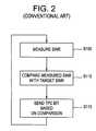
- FIG. 2illustrates a conventional inner loop CDMA reverse link power control process.
- the process of FIG. 2is described below as performed with respect to the reverse link from the UE 105 to the Node B 120 .
- the process of FIG. 2is representative of a conventional CDMA reverse link power control between any UE in connection with any Node B.
- the Node B(e.g., Node B 120 ) measures the SINR for pilot transmissions received from a UE (e.g., UE 105 ) in step S 105 .
- the measured SINR measurement(step S 105 ) is either a pre- or post-interference cancellation (IC) measurement.
- ICpost-interference cancellation
- the Node B 120measures the pilot SINR prior to interference cancellation, and then measures the residual interference-to-total interference ratio after the interference cancellation. The ratio of these two quantities is a measure of the post-interference cancellation SINR.
- the Node B 120compares the measured pilot SINR with an adaptive target SINR in step S 110 .
- the adaptive SINR targetis previously set by the outer loop at the RNC 130 so as to satisfy a level of Quality of Service (QoS), reflected by an expected packet error rate (PER) or FER, for each served UE (e.g., UE 105 , 120 , etc.).
- QoSQuality of Service
- PERpacket error rate
- FERpacket error rate
- the adaptive SINR targetis not the only factor affecting the QoS, however, and the adaptive SINR is set with a consideration of such other factors so as to more accurately tune to the desired level of QoS.
- another factor potentially affecting the QoSis a traffic-to-pilot ratio (TPR) at the UE 105 .
- TPRtraffic-to-pilot ratio
- the TPR at the UE 105is fixed, and does not “adapt” as described above with respect to the adaptive target SINR.
- “fixed” TPRmeans that,
- the Node B 120sends a transmit power control (TPC) bit to the UE 105 in step S 115 .
- a TPC bitis a single bit binary indicator, which is set to a first logic level (e.g., a higher logic level or “1”) to instruct a UE (e.g., UE 105 ) to increase transmission power by a fixed amount and a second logic level (e.g., a lower logic level or “0”) to instruct a UE (e.g., UE 105 ) to decrease transmission power by the fixed amount.
- a first logic levele.g., a higher logic level or “1”
- a second logic levele.g., a lower logic level or “0”
- step S 110if the comparison of step S 110 indicates that the measured pilot SINR is less than the adaptive target SINR, the Node B 120 sends a TPC bit having the first logic level (e.g., a higher logic level or “1”) to the UE 105 . Otherwise, the Node B 120 sends a TPC bit having the second logic level (e.g., a lower logic level or “0”) to the UE 105 . After the Node B 120 sends the TPC bit to the UE 105 in step S 115 , the process returns to step S 105 .
- the first logic levele.g., a higher logic level or “1”
- the Node B 120sends a TPC bit having the second logic level (e.g., a lower logic level or “0”) to the UE 105 .
- the processreturns to step S 105 .
- the frequency at which the Node B 120 measures(step S 105 ) the pilot SINR, compares the measured pilot SINR with the adaptive target SINR (step S 110 ) and sends TPC bits (step S 115 ) may be based on a desired “tightness” of power control as determined by a system engineer.
- the RNC 130While the process of FIG. 2 is being performed at the Node B 120 , at the outer loop, the RNC 130 periodically determines whether to adjust the adaptive target SINR based on an analysis of the inner loop communications. This determination may be based on a number of criteria. For example, the RNC 130 decreases the adaptive target SINR if the PER or FER is relatively low (e.g., very few non-acknowledgments (NACKs) are sent to the UE 105 indicating failed transmissions) so as to satisfy a given level of QoS. In another example, the RNC 130 increases the adaptive target SINR if the PER is relatively high (e.g., too many NACKs are being sent to the UE 105 ) so as to satisfy a given level of QOS. The RNC 130 then updates the adaptive target SINR used by the Node B 120 in the process of FIG. 2 in accordance with the determined adjustment.
- the RNC 130updates the adaptive target SINR used by the Node B 120 in the process of FIG. 2 in
- An example embodiment of the present inventionis directed to a method of controlling reverse link transmission power in a wireless communications network, including measuring a signal-to-interference+noise (SINR) for a plurality of mobile stations, determining a power control adjustment for each of the mobile stations based on the measured SINR for the mobile station and a fixed target SINR, the fixed target SINR being used in the determining step for each mobile station and sending the power control adjustments to the mobile stations.
- SINRsignal-to-interference+noise
- Another example embodiment of the present inventionis directed to a method of controlling reverse link transmission power in a wireless communications network, including transmitting one or more signals to a base station and receiving a power control adjustment indicator indicating an adjustment to a transmission power level, the received power control adjustment having been determined based on a measured signal-to-interference+noise ratio (SINR) for the one or more transmitted signals and a fixed target SINR threshold, the fixed target SINR threshold being used for power control adjustment of a plurality of mobile stations.
- SINRsignal-to-interference+noise ratio
- FIG. 1illustrates a conventional Code Division Multiple Access (CDMA) system.
- CDMACode Division Multiple Access
- FIG. 2illustrates a conventional inner loop CDMA reverse link power control process.
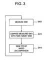
- FIG. 3illustrates a CDMA reverse link power control process according to an example embodiment of the present invention.
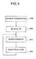
- FIG. 4illustrates a CDMA reverse link power control process according to another example embodiment of the present invention.
- FIG. 5illustrates a process of establishing a maximum transmit power per chip threshold for a mobile station's transmissions according to an example embodiment of the present invention.
- a CDMA reverse link power control processwill be described below with respect to the conventional CDMA system 100 of FIG. 1 . More specifically, the embodiment will be described below as performed with respect to the reverse link from the UE 105 to the Node B 120 . However, it is understood that the embodiment may also be representative of CDMA reverse link power control between any UE in connection with any Node B. Furthermore, it will be appreciated that the processes of the present invention are not limited to the CDMA system of FIG. 1 .
- the RNC 130selects a fixed target SINR or E b /N 0 system.
- the fixed target SINRis fixed for all UEs within the CDMA system 100 , and is used in the inner loop for evaluating measured pilot SINRs in order to determine whether transmission power adjustments should be made.
- the fixed target SINRmay be set in conjunction with an initial traffic-to-pilot ratio or TPR to maintain expected CDMA control channel error rates below an error rate threshold. Error rates (e.g., a frame error rate (FER), a packet error rate (PER), etc.) reflect a Quality of Service (QoS) provided to the UE 105 .
- FERframe error rate
- PERpacket error rate
- the target SINR and the TPRare two factors which potentially affect the QoS for the UE 105 .
- the RNC 130sets the fixed target SINR and the TPRs based on offline link level curves for each served UE conservatively such that the UEs, including the UE 105 , are very likely to attain a threshold QoS level.
- the setting of “initial” values for the target SINR and the TPRsis well known in the art.
- an example embodiment of the present inventionis directed to maintaining the target SINR at a constant level while adapting the TPR for each served UE.
- the inner loop power control performed at, for example, a Node B such as Node B 120is illustrated in FIG. 3 .
- the Node B 120measures an SINR for a pilot signal received from the UE 105 in step S 405 .
- the measured SINR measurement (step S 405 )is either a pre- or post-interference cancellation (IC) measurement.
- ICpost-interference cancellation
- the Node B 120measures the pilot SINR prior to interference cancellation, and then measures the residual interference-to-total interference ratio after the interference cancellation. The ratio of these two quantities is a measure of the post-interference cancellation SINR.
- the Node B 120compares the measured pilot SINR with the fixed target SINR in step S 410 .
- the Node B 120sends a transmit power control (TPC) bit to the UE 105 in step S 415 .
- the TPC bitis a single bit binary indicator which is set to a first logic level (e.g., a higher logic level or “1”) to instruct a UE (e.g., UE 105 ) to increase transmission power by a fixed amount and a second logic level (e.g., a lower logic level or “0”) to instruct a UE (e.g., UE 105 ) to decrease transmission power by the fixed amount.
- a first logic levele.g., a higher logic level or “1”
- a second logic levele.g., a lower logic level or “0”
- step S 410if the comparison of step S 410 indicates that the measured pilot SINR is less than the fixed target SINR, the Node B 120 sends a TPC bit having the first logic level (e.g., a higher logic level or “1”) to the UE 105 . Otherwise, the Node B 120 sends a TPC bit having the second logic level (e.g., a lower logic level or “0”) to the UE 105 .
- the frequency at which the Node B 120 measuresmay be based on a desired “tightness” of power control as determined by a system engineer.
- FIG. 4illustrates a CDMA reverse link power control process according to another example embodiment of the present invention.
- the process of FIG. 4illustrates steps performed at, for example the UE 105 .
- the UE 105may be served by the Node B 120 operating in accordance with the process of FIG. 3 .
- step S 500the UE 105 establishes communication with the Node B 120 using well-known methods. While data is being transferred between the UE 105 and the Node B 120 , the Node B 120 will periodically send acknowledgments (ACKs) and non-ACKs (NACKs) to the UE 105 to indicate successful or unsuccessful transmissions from the UE 105 .
- CDMA transmissionstypically include a pilot channel, a plurality of control channels (e.g., for sending channel quality indicators (CQIs), etc.) and a plurality of traffic channels. The plurality of control channels and the pilot channel do not typically receive error feedback (e.g., ACKs/NACKs). Rather, error feedback is typically isolated to the CDMA traffic channels.
- CQIschannel quality indicators
- a conservative initial traffic-to-pilot ratiois set in step S 505 such that error rates for the plurality of control channels are expected to remain below an error rate threshold.
- the TPR multiplied by the power level of the pilot signal of the UE 105is the power level for transmissions on traffic channels of the UE 105 .
- the initial TPRmay be set in conjunction with the target SINR to conservative levels in order to maintain the control channel error rates below the error rate threshold.
- the target SINR and the TPRare two factors which potentially affect the QoS for the UE 105 .
- the RNC 130sets the fixed target SINR and the initial TPRs for each served UE conservatively such that the UEs, including the UE 105 , are very likely to attain a threshold QoS level, as reflected by FER, PER, etc.
- the initial TPRmay be a system designer's “best guess” for a good starting point for an adaptive TPR.
- the value of the initial TPRis not critical for the operation of the process of FIG. 4 because, as will be discussed below, the initial TPR is updated or adjusted to reflect and respond to actual operating conditions.
- the UE 105receives ACKs/NACKs from the Node B 120 in response to data packets transmitted to the Node B 120 in step S 510 . Based on the received ACKs/NACKs, the UE 105 determines whether the actual, current error rate is below the error rate threshold in step S 515 . As discussed above, the initial TPR is set (step S 505 ) based on an expected error rate. Thereafter, the TPR is adjusted by the UE 105 in step S 515 based on actual operating conditions. If the actual operating conditions indicate that the error rate is above the error rate threshold (e.g., worse than expected), the TPR is increased (e.g., by a first fixed amount) in step 515 .
- the initial TPRis set (step S 505 ) based on an expected error rate.
- the TPRis adjusted by the UE 105 in step S 515 based on actual operating conditions. If the actual operating conditions indicate that the error rate is above the error rate threshold (e.g., worse than expected),
- the TPRis increased by the first fixed amount.
- the TPRis decreased (e.g., by a second fixed amount) in step S 515 .
- the TPRis decreased by the second fixed amount.
- the TPR_downstep/TPR_upstepx/(1 ⁇ x) . In this case, whenever a packet succeeds in less than 4 attempts, the TPR is decreased by TPR_downstep, and if it fails after 4 attempts, the TPR is increased by TPR_upstep.
- the transmit power levels set by the TPRmay have both physical constraints and software constraints.
- a physical constraint of the transmit power level set by the TPRis an actual physical transmission threshold (i.e., a maximum transmission power level for the UE 105 at its highest power settings).
- a software constraintis an artificial maximum transmit power level (e.g., hereinafter referred to as a “maximum transmit power per chip threshold”) typically set by the outer loop so as to reduce overall system interference by not allowing all users to transmit at their highest possible levels. An example of establishing the maximum transmit power per chip threshold is described later with respect to FIG. 5 .
- the continual adjustment of the TPR in step S 515 for Hybrid-ARQ (HARQ) channelsmay allow a target PER or QoS to achieve a given threshold after a given number of transmissions based on the ACKs/NACKs received in step S 510 .
- HARQHybrid-ARQ
- the UE 105if the UE 105 is engaged in soft handoff (e.g., with Node Bs 120 and 125 ), the UE 105 receives ACKs/NACKs on multiple legs (e.g., from multiple Node Bs) and the determination of the actual error rate in step S 515 is thereby based on ACKs/NACKs in a plurality of sectors.
- the TPR adjustment performed in step S 515is based on the ACKs/NACKs received from the Node Bs 120 / 125 involved in the soft handoff.
- a SINR target update procedureconventionally performed at the outer loop (e.g., at RNC 130 ), need not be performed. Thereby, numerous frames conventionally devoted to the SINR target update procedures may be used for other purposes.
- the processing conventionally performed by the outer loop or RNC 130is offloaded onto the UE 105 in example embodiments of the present invention because the UE 105 , when engaged in soft handoff, uses the ACKs/NACKs from all Node Bs 120 / 125 in its active set (e.g., a set of Node Bs with which the UE 105 communicates with during soft handoff) to determine whether to adjust the TPR, in contrast to the outer loop or RNC 130 determining whether to adjust the target SINR.
- the active sete.g., a set of Node Bs with which the UE 105 communicates with during soft handoff
- CDMA reverse link power control processwas described as implemented within the conventional CDMA system 100 of FIG. 1 , the CDMA reverse link power control process may alternatively be applied in any system capable of operating in accordance with CDMA protocols, such as a hybrid Orthogonal Frequency Division Multiple Access (OFDMA)/CDMA system.
- OFDMAOrthogonal Frequency Division Multiple Access
- maintaining the fixed target SINRmay simplify OFDMA reverse link power control because the CDMA measured pilot SINR (e.g., which may be used in an OFDMA reverse link power control process) may be predicted with greater accuracy at the UE 105 .
- the CDMA measured pilot SINRe.g., which may be used in an OFDMA reverse link power control process
- the above-described CDMA reverse link power control processmay be employed at an interference cancellation receiver because the TPRs at the UEs (e.g., UE 105 ) may be adjusted in step S 520 to account for interference at a plurality of traffic channels.
- UEs located near edges or boundaries of cellshave more affect on neighboring cell's interference as compared to UEs located in close proximity to a serving Node B (e.g., near a centered position of the cell). If no control is maintained on the peak power with which a given UE may transmit, overall system interference may increase.
- the following example of establishing a peak power per chip or maximum transmit power level for a UE within the conventional CDMA system 100is given as a function of the UE's location with respect to a plurality of cells.
- Each of the Node Bs(e.g., Node Bs 120 , 125 , etc.) within the CDMA system 100 periodically measures an amount of received outer-cell interference (e.g., interference from cells other than a Node B's own cell).
- Each of the Node Bscompares the measured outer-cell interference with an outer-cell interference threshold Io thresh .
- the RNC 130may set the outer-cell interference threshold Io thresh for the Node Bs 120 / 125
- Each of the k Node Bstransmits (e.g., to all UEs within range, such as the UE 105 ) an Interference Activity Bit (IAB) based on the comparison.
- IABInterference Activity Bit
- the IABsmay be transmitted from one or more Node Bs at once such that multiple IABs may be received by a UE within the CDMA system 100 , in part based on the UE's position relative to neighboring or serving Node Bs within the CDMA system 100 .
- a maximum transmit power per chip threshold adjustment process, performed at the UEs within the CDMA system 100 , taking into account the IABs transmitted by the Node Bswill now be described below with respect to a representative UE 105 in FIG. 5 .
- FIG. 5illustrates a process of establishing a maximum transmit power per chip threshold for a UE's transmissions according to an example embodiment of the present invention.
- the example embodiment of FIG. 5is described below with respect to a representative UE (e.g., UE 105 ) and k Node Bs (e.g., Node B 120 , 125 , etc.) within the conventional CDMA system 100 , wherein k is an integer greater than or equal to 1.
- the steps illustrated in FIG. 5 and described beloware performed at, for example, the UE 105 of FIG. 1 .
- the representative UE 105is not necessarily in active communication with more than one of the k Node Bs (e.g., although it may be, such as in soft handoff mode), but the representative UE 105 is capable of “listening” to or receiving signals from all of the k Node Bs. Accordingly, it will be appreciated that the number k may vary based on the UE 105 's position within the CDMA system 100 . For example, if the UE 105 is in very close proximity to a serving Node B such as Node B 120 , k typically equals 1. As the UE 105 becomes closer to an edge of a cell, k is typically greater than 1.
- Pmax( 1 )denotes a maximum power for an initial time period
- Io threshdenotes an outer-cell interference threshold (e.g., an amount of outer-cell interference that can be tolerated)
- G(d)denotes an average channel gain from the UE 105 to a dth Node B among the k Node Bs, wherein d is an integer from 1 to k.
- the G(d) measurementsare based on SINR measurements on the common pilot and preamble
- the outer-cell interference threshold Io threshis determined by a design engineer.
- the UE 105receives the IABs (discussed above prior to FIG. 5 ) from each of the k Node Bs in step 605 and determines whether an adjustment to the maximum transmit power per chip threshold is required in step S 610 . If step S 610 determines that an adjustment is necessary, a power adjustment is calculated for the UE 305 in step S 615 . Otherwise, the process returns to step S 605 .
- the probability “x”is based on a coverage requirement for the given Node B (e.g., Node B 120 ).
- the probability “x”is determined during deployment or installation of the CDMA system 100 .
- P marginis an offset value which is greater than or equal to 0 to ensure the bucket does not become empty during the transmission of the encoder packet.
- a data rate for the new encoder packetis selected such that P max (t) is set to a sufficient power level so as to achieve a threshold level of spectral efficiency.
- step S 615Once the maximum transmit power per chip threshold P max (t) is set in accordance with one of Equations 7 and 8 in step S 615 , the process returns to step S 605 .
- UEs closer to a greater number of Node Bsadjust the maximum transmit power per chip threshold with larger steps, whereas UEs closer in proximity to the serving Node B react more slowly to the IAB bits.
- the combination of the pilot reference power (Po(t)) and the maximum allowed data/pilot power per chipmay be used in the computation of the spectral efficiency as requested by the UE.
- a Node B and a UEmay alternatively be referred to as a base station (BS) and a mobile station (MS) or mobile unit (MU), respectively.
- BSbase station
- MSmobile station
- MUmobile unit
Landscapes
- Engineering & Computer Science (AREA)
- Computer Networks & Wireless Communication (AREA)
- Signal Processing (AREA)
- Quality & Reliability (AREA)
- Mobile Radio Communication Systems (AREA)
Abstract
Description
Pmax(1)=Iothresh/max(G(d)),d=1, . . . , k Equation 3
wherein Pmax(1) denotes a maximum power for an initial time period, Iothreshdenotes an outer-cell interference threshold (e.g., an amount of outer-cell interference that can be tolerated), and G(d) denotes an average channel gain from the
Pcbucket(t)=Pcbucket(t−1)−ΔPdown Equation 4
if any of the IABs received by the
Pcbucket(t)=Pcbucket(t−1)+ΔPup Equation 5
if all of the IABs received by the
ΔPup=[x/(1−x)]ΔPdown
wherein x is equal to the probability that the outer-cell interference measured by a given Node Bis greater than the outer-cell interference threshold Iothresh. In an example, the probability “x” is based on a coverage requirement for the given Node B (e.g., Node B120). In a further example, the probability “x” is determined during deployment or installation of the CDMA system100.
Pbucket(t)=Pbucket(t−1)+Pcbucket(t)−Pmax(t−1) Equation 6
Pmax(t)=min(Pmax(t−1),Pbucket(t)) Equation 7
Pmax(t)=Pbucket(t)−Pmargin Equation 8
Claims (8)
Priority Applications (14)
| Application Number | Priority Date | Filing Date | Title |
|---|---|---|---|
| US11/355,977US8712460B2 (en) | 2006-02-17 | 2006-02-17 | Methods of reverse link power control |
| CN201510992943.1ACN105554866B (en) | 2006-02-17 | 2007-02-13 | The method of power of reverse link control |
| CNA2007800056147ACN101385251A (en) | 2006-02-17 | 2007-02-13 | Method for reverse link power control |
| PCT/US2007/003900WO2007097960A1 (en) | 2006-02-17 | 2007-02-13 | Methods of reverse link power control |
| RU2008137034/09ARU2433534C2 (en) | 2006-02-17 | 2007-02-13 | Method of regulating return channel power |
| EP07750721.8AEP1985033B1 (en) | 2006-02-17 | 2007-02-13 | Methods of reverse link power control |
| JP2008555323AJP2009527198A (en) | 2006-02-17 | 2007-02-13 | Reverse link power control method |
| AU2007217989AAU2007217989B2 (en) | 2006-02-17 | 2007-02-13 | Methods of reverse link power control |
| KR1020087019634AKR101395582B1 (en) | 2006-02-17 | 2007-02-13 | Methods of reverse link power control |
| BRPI0707774-2ABRPI0707774B1 (en) | 2006-02-17 | 2007-02-13 | REVERSE LINK POWER CONTROL METHODS |
| TW096106362ATWI437836B (en) | 2006-02-17 | 2007-02-16 | Reverse link power control method |
| IL193389AIL193389A (en) | 2006-02-17 | 2008-08-12 | Methods of reverse link power control |
| JP2013147316AJP5869528B2 (en) | 2006-02-17 | 2013-07-16 | Reverse link power control method |
| US14/245,103US8989799B2 (en) | 2006-02-17 | 2014-04-04 | Methods of reverse link power control |
Applications Claiming Priority (1)
| Application Number | Priority Date | Filing Date | Title |
|---|---|---|---|
| US11/355,977US8712460B2 (en) | 2006-02-17 | 2006-02-17 | Methods of reverse link power control |
Related Child Applications (1)
| Application Number | Title | Priority Date | Filing Date |
|---|---|---|---|
| US14/245,103ContinuationUS8989799B2 (en) | 2006-02-17 | 2014-04-04 | Methods of reverse link power control |
Publications (2)
| Publication Number | Publication Date |
|---|---|
| US20070197251A1 US20070197251A1 (en) | 2007-08-23 |
| US8712460B2true US8712460B2 (en) | 2014-04-29 |
Family
ID=38162218
Family Applications (2)
| Application Number | Title | Priority Date | Filing Date |
|---|---|---|---|
| US11/355,977Active2028-10-09US8712460B2 (en) | 2006-02-17 | 2006-02-17 | Methods of reverse link power control |
| US14/245,103ActiveUS8989799B2 (en) | 2006-02-17 | 2014-04-04 | Methods of reverse link power control |
Family Applications After (1)
| Application Number | Title | Priority Date | Filing Date |
|---|---|---|---|
| US14/245,103ActiveUS8989799B2 (en) | 2006-02-17 | 2014-04-04 | Methods of reverse link power control |
Country Status (11)
| Country | Link |
|---|---|
| US (2) | US8712460B2 (en) |
| EP (1) | EP1985033B1 (en) |
| JP (2) | JP2009527198A (en) |
| KR (1) | KR101395582B1 (en) |
| CN (2) | CN101385251A (en) |
| AU (1) | AU2007217989B2 (en) |
| BR (1) | BRPI0707774B1 (en) |
| IL (1) | IL193389A (en) |
| RU (1) | RU2433534C2 (en) |
| TW (1) | TWI437836B (en) |
| WO (1) | WO2007097960A1 (en) |
Families Citing this family (39)
| Publication number | Priority date | Publication date | Assignee | Title |
|---|---|---|---|---|
| US8260340B2 (en) | 2006-02-17 | 2012-09-04 | Alcatel Lucent | Methods of reverse link power control |
| US20070237217A1 (en)* | 2006-04-06 | 2007-10-11 | Zukang Shen | User scheduling methods and apparatus for high-speed uplink packet access systems |
| WO2007144956A1 (en)* | 2006-06-16 | 2007-12-21 | Mitsubishi Electric Corporation | Mobile communication system and mobile terminal |
| KR100961888B1 (en)* | 2006-08-07 | 2010-06-09 | 삼성전자주식회사 | Apparatus and Method for Eliminating Interference in Wireless Communication Systems |
| US8005026B2 (en)* | 2007-06-29 | 2011-08-23 | Intel Corporation | Multiple radio platform transmission power control |
| CN101897129B (en)* | 2007-12-14 | 2013-03-13 | 艾利森电话股份有限公司 | Method and device for adjusting transmission power by adjusting gain factor in communication system |
| US7974197B2 (en)* | 2008-01-25 | 2011-07-05 | Alcatel-Lucent Usa Inc. | Method of prioritizing user throughput and user throughput limits for best-effort application in cdma2000 1xEV-DO wireless communication system |
| US8285321B2 (en)* | 2008-05-15 | 2012-10-09 | Qualcomm Incorporated | Method and apparatus for using virtual noise figure in a wireless communication network |
| KR20100019010A (en)* | 2008-08-08 | 2010-02-18 | 삼성전자주식회사 | Signal receiving apparatus, broadcasting receiving apparatus and signal processing method using the same |
| CN101651476B (en)* | 2008-08-14 | 2013-02-27 | 华为技术有限公司 | Method and wireless access device for limiting terminal transmission power |
| WO2010098970A2 (en)* | 2009-02-24 | 2010-09-02 | Elliott Hoole | Usage-based output power level adjustments for self-optimizing radio access nodes |
| US9351340B2 (en)* | 2009-04-08 | 2016-05-24 | Nokia Technologies Oy | Apparatus and method for mode selection for device-to-device communications |
| US20100332871A1 (en)* | 2009-06-30 | 2010-12-30 | International Buisness Machines Corporation | Capping power consumption in a data storage system |
| KR101273082B1 (en)* | 2009-12-15 | 2013-06-10 | 한국전자통신연구원 | Method and system for generating feedback for uplink transmit power control |
| US9515773B2 (en) | 2010-04-13 | 2016-12-06 | Qualcomm Incorporated | Channel state information reporting in a wireless communication network |
| US9350475B2 (en) | 2010-07-26 | 2016-05-24 | Qualcomm Incorporated | Physical layer signaling to user equipment in a wireless communication system |
| US8886250B2 (en) | 2010-06-18 | 2014-11-11 | Qualcomm Incorporated | Channel quality reporting for different types of subframes |
| US20110250919A1 (en) | 2010-04-13 | 2011-10-13 | Qualcomm Incorporated | Cqi estimation in a wireless communication network |
| US9307431B2 (en) | 2010-04-13 | 2016-04-05 | Qualcomm Incorporated | Reporting of channel properties in heterogeneous networks |
| CN102271389B (en)* | 2010-06-04 | 2014-03-19 | 中兴通讯股份有限公司 | Uplink power control method and system |
| US9136953B2 (en)* | 2010-08-03 | 2015-09-15 | Qualcomm Incorporated | Interference estimation for wireless communication |
| US8855000B2 (en) | 2011-04-28 | 2014-10-07 | Qualcomm Incorporated | Interference estimation using data traffic power and reference signal power |
| US8849298B2 (en)* | 2012-01-18 | 2014-09-30 | Lg-Ericsson Co., Ltd. | Transmit power setting method and mobile telecommunication system using the same |
| US20130201917A1 (en)* | 2012-02-08 | 2013-08-08 | Qualcomm Incorporated | Dynamic indication of traffic to pilot (t/p) ratios |
| WO2013166729A1 (en)* | 2012-05-11 | 2013-11-14 | 华为技术有限公司 | Method, device, and system for reporting signal quality measurement result |
| US9185661B2 (en) | 2012-06-04 | 2015-11-10 | Nokia Solutions And Networks Oy | Performing power control based on nominal packet size |
| EP2862394B1 (en)* | 2012-06-14 | 2017-08-09 | Telefonaktiebolaget LM Ericsson (publ) | Transmit power control |
| US9319916B2 (en) | 2013-03-15 | 2016-04-19 | Isco International, Llc | Method and appartus for signal interference processing |
| EP3005800B1 (en)* | 2013-06-03 | 2018-09-26 | Telefonaktiebolaget LM Ericsson (publ) | Method and arrangement for d2d communication |
| US9794888B2 (en) | 2014-05-05 | 2017-10-17 | Isco International, Llc | Method and apparatus for increasing performance of a communication link of a communication node |
| CN105142160B (en)* | 2015-09-15 | 2018-12-11 | 中国联合网络通信集团有限公司 | A kind of method and device of interference coordination |
| EP3385859B1 (en)* | 2017-04-03 | 2025-06-04 | Mitsubishi Electric R & D Centre Europe B.V. | Method for building sinr data from power measurements data |
| US10298279B2 (en) | 2017-04-05 | 2019-05-21 | Isco International, Llc | Method and apparatus for increasing performance of communication paths for communication nodes |
| CN107172694A (en)* | 2017-05-18 | 2017-09-15 | 迈锐数据(北京)有限公司 | A kind of power adaptive adjusting method and device |
| US10284313B2 (en) | 2017-08-09 | 2019-05-07 | Isco International, Llc | Method and apparatus for monitoring, detecting, testing, diagnosing and/or mitigating interference in a communication system |
| CN109561509B (en)* | 2017-09-25 | 2023-04-07 | 中兴通讯股份有限公司 | Method and device for reverse resource allocation of wireless communication system |
| US10863570B2 (en) | 2018-01-09 | 2020-12-08 | Comcast Cable Communications, Llc | Beam selection in beam failure recovery request retransmission |
| CN109362098B (en)* | 2018-11-23 | 2022-06-14 | 赛尔通信服务技术股份有限公司 | Method and device for identifying 4G mobile communication interference signal |
| EP3716681B1 (en)* | 2019-03-28 | 2021-05-05 | Mitsubishi Electric R&D Centre Europe B.V. | Admission control delegation for moving iab |
Citations (15)
| Publication number | Priority date | Publication date | Assignee | Title |
|---|---|---|---|---|
| EP0682418A2 (en) | 1994-05-12 | 1995-11-15 | Ntt Mobile Communications Network Inc. | Transmission power control for mobile radio |
| KR20010021080A (en) | 1999-07-16 | 2001-03-15 | 루센트 테크놀러지스 인크 | Synchronization of transmit power level settings for soft-handoff in wireless systems by the use of power level constraints |
| KR20010023790A (en) | 1997-09-08 | 2001-03-26 | 밀러 럿셀 비 | Method and system for changing forward traffic channel power allocation during soft handoff |
| JP2002026747A (en) | 2000-07-13 | 2002-01-25 | Matsushita Electric Ind Co Ltd | Wireless communication terminal device and transmission power control method |
| EP1311076A1 (en) | 2001-11-12 | 2003-05-14 | Lucent Technologies Inc. | Control of the transmission power of a CMDA based system |
| US6587696B1 (en)* | 1998-07-31 | 2003-07-01 | Nokia Mobile Phones Limited | Power control technique utilizing forward pilot channel |
| US6690944B1 (en)* | 1999-04-12 | 2004-02-10 | Nortel Networks Limited | Power control of a multi-subchannel mobile station in a mobile communication system |
| WO2004059875A1 (en) | 2002-12-30 | 2004-07-15 | Koninklijke Philips Electronics N.V. | An adaptive step size method for power control in wireless communication system and a system for the same |
| WO2004093343A1 (en) | 2003-04-11 | 2004-10-28 | Qualcomm Incorporated | System and method for fluid power control of a reverse link communication |
| US20050111397A1 (en)* | 2002-12-06 | 2005-05-26 | Attar Rashid A. | Hybrid TDM/OFDM/CDM reverse link transmission |
| JP2005159577A (en) | 2003-11-21 | 2005-06-16 | Toshiba Corp | Wireless communication system, mobile communication terminal apparatus, base station apparatus, and wireless communication method |
| US20050143120A1 (en) | 2003-11-17 | 2005-06-30 | Interdigital Technology Corporation | Method, access point and WTRU for controlling transmission power levels of uplink/downlink communication in a wireless communication system |
| US6968201B1 (en) | 1999-10-06 | 2005-11-22 | Lucent Technologies, Inc. | Method and apparatus for controlling reverse link interference rise and power control instability in a wireless system |
| US20060211441A1 (en)* | 2005-03-15 | 2006-09-21 | Murat Mese | Power control and overlapping control for a quasi-orthogonal communication system |
| US20080009244A1 (en)* | 2004-07-27 | 2008-01-10 | Nec Corporation | Method Of Uplink Radio Resource Control, Base Station Apparatus, And Radio Network Controller |
Family Cites Families (11)
| Publication number | Priority date | Publication date | Assignee | Title |
|---|---|---|---|---|
| US6512925B1 (en)* | 1998-12-03 | 2003-01-28 | Qualcomm, Incorporated | Method and apparatus for controlling transmission power while in soft handoff |
| FI115268B (en)* | 2000-05-12 | 2005-03-31 | Nokia Corp | Power control in a radio system |
| US8605686B2 (en)* | 2001-02-12 | 2013-12-10 | Qualcomm Incorporated | Method and apparatus for power control in a wireless communication system |
| CN1184764C (en)* | 2001-09-25 | 2005-01-12 | 华为技术有限公司 | Backward external ring power control method in CDMA communication system |
| JP4105920B2 (en)* | 2002-08-23 | 2008-06-25 | 松下電器産業株式会社 | Target SIR setting method for outer loop transmission power control |
| US20040047305A1 (en)* | 2002-08-27 | 2004-03-11 | Fatih Ulupinar | Distributed reverse channel outer loop power control for a wireless communications system |
| JP4127805B2 (en)* | 2003-04-11 | 2008-07-30 | 株式会社エヌ・ティ・ティ・ドコモ | Base station, mobile station, communication system, transmission control method, and mobile station control program |
| US7738901B2 (en)* | 2003-07-10 | 2010-06-15 | Telefonaktiebolaget Lm Ericsson (Publ) | Secondary link power control in a wireless communication network |
| US7724701B2 (en)* | 2003-09-30 | 2010-05-25 | Qualcomm Incorporated | Method and apparatus for controlling reverse link data rate of a mobile station in a communication system with reverse link common rate control |
| US8452316B2 (en)* | 2004-06-18 | 2013-05-28 | Qualcomm Incorporated | Power control for a wireless communication system utilizing orthogonal multiplexing |
| CN102105418A (en) | 2008-07-03 | 2011-06-22 | 日立金属株式会社 | Silicon nitride board, method for manufacturing the silicon nitride board, and silicon nitride circuit board and semiconductor module using the silicon nitride board |
- 2006
- 2006-02-17USUS11/355,977patent/US8712460B2/enactiveActive
- 2007
- 2007-02-13CNCNA2007800056147Apatent/CN101385251A/enactivePending
- 2007-02-13WOPCT/US2007/003900patent/WO2007097960A1/enactiveApplication Filing
- 2007-02-13EPEP07750721.8Apatent/EP1985033B1/enactiveActive
- 2007-02-13RURU2008137034/09Apatent/RU2433534C2/enactive
- 2007-02-13CNCN201510992943.1Apatent/CN105554866B/enactiveActive
- 2007-02-13JPJP2008555323Apatent/JP2009527198A/enactivePending
- 2007-02-13AUAU2007217989Apatent/AU2007217989B2/enactiveActive
- 2007-02-13BRBRPI0707774-2Apatent/BRPI0707774B1/enactiveIP Right Grant
- 2007-02-13KRKR1020087019634Apatent/KR101395582B1/ennot_activeExpired - Fee Related
- 2007-02-16TWTW096106362Apatent/TWI437836B/ennot_activeIP Right Cessation
- 2008
- 2008-08-12ILIL193389Apatent/IL193389A/enactiveIP Right Grant
- 2013
- 2013-07-16JPJP2013147316Apatent/JP5869528B2/enactiveActive
- 2014
- 2014-04-04USUS14/245,103patent/US8989799B2/enactiveActive
Patent Citations (19)
| Publication number | Priority date | Publication date | Assignee | Title |
|---|---|---|---|---|
| US5566165A (en)* | 1994-05-12 | 1996-10-15 | Ntt Mobile Communications Network Inc. | Transmission power control method and a communication system using the same |
| EP0682418A2 (en) | 1994-05-12 | 1995-11-15 | Ntt Mobile Communications Network Inc. | Transmission power control for mobile radio |
| KR20010023790A (en) | 1997-09-08 | 2001-03-26 | 밀러 럿셀 비 | Method and system for changing forward traffic channel power allocation during soft handoff |
| US6307849B1 (en) | 1997-09-08 | 2001-10-23 | Qualcomm Incorporated | Method and system for changing forward traffic channel power allocation during soft handoff |
| US6587696B1 (en)* | 1998-07-31 | 2003-07-01 | Nokia Mobile Phones Limited | Power control technique utilizing forward pilot channel |
| US6690944B1 (en)* | 1999-04-12 | 2004-02-10 | Nortel Networks Limited | Power control of a multi-subchannel mobile station in a mobile communication system |
| US6628957B1 (en) | 1999-07-16 | 2003-09-30 | Lucent Technologies Inc. | Synchronization of transmit power level settings for soft-handoff in wireless systems by the use of level constraints |
| KR20010021080A (en) | 1999-07-16 | 2001-03-15 | 루센트 테크놀러지스 인크 | Synchronization of transmit power level settings for soft-handoff in wireless systems by the use of power level constraints |
| US6968201B1 (en) | 1999-10-06 | 2005-11-22 | Lucent Technologies, Inc. | Method and apparatus for controlling reverse link interference rise and power control instability in a wireless system |
| JP2002026747A (en) | 2000-07-13 | 2002-01-25 | Matsushita Electric Ind Co Ltd | Wireless communication terminal device and transmission power control method |
| EP1311076A1 (en) | 2001-11-12 | 2003-05-14 | Lucent Technologies Inc. | Control of the transmission power of a CMDA based system |
| US20050111397A1 (en)* | 2002-12-06 | 2005-05-26 | Attar Rashid A. | Hybrid TDM/OFDM/CDM reverse link transmission |
| WO2004059875A1 (en) | 2002-12-30 | 2004-07-15 | Koninklijke Philips Electronics N.V. | An adaptive step size method for power control in wireless communication system and a system for the same |
| WO2004093343A1 (en) | 2003-04-11 | 2004-10-28 | Qualcomm Incorporated | System and method for fluid power control of a reverse link communication |
| US20050143120A1 (en) | 2003-11-17 | 2005-06-30 | Interdigital Technology Corporation | Method, access point and WTRU for controlling transmission power levels of uplink/downlink communication in a wireless communication system |
| US20080132267A1 (en)* | 2003-11-17 | 2008-06-05 | Interdigital Technology Corporation | Method, access point and wtru for controlling transmission power levels of uplink/downlink communication in a wireless communication system |
| JP2005159577A (en) | 2003-11-21 | 2005-06-16 | Toshiba Corp | Wireless communication system, mobile communication terminal apparatus, base station apparatus, and wireless communication method |
| US20080009244A1 (en)* | 2004-07-27 | 2008-01-10 | Nec Corporation | Method Of Uplink Radio Resource Control, Base Station Apparatus, And Radio Network Controller |
| US20060211441A1 (en)* | 2005-03-15 | 2006-09-21 | Murat Mese | Power control and overlapping control for a quasi-orthogonal communication system |
Non-Patent Citations (6)
| Title |
|---|
| Chinese Office Action dated Jun. 5, 2012, issued in Chinese Application No. 200780005614.7 and English translation thereof. |
| Examiner's Office Letter dated Mar. 21, 2012, issued in Japanese Patent Application No. 2008-555323 and English translation thereof. |
| Examiner's Refusal Decision dated Mar. 14, 2013 for related Japanese Application No. 2008-555323 (full translation provided). |
| International Search Report and Written Opinion dated Jul. 3, 2007. |
| Office Action for corresponding Israeli Application No. 193389 dated Jan. 19, 2012. |
| Taiwanese Office Action dated Mar. 29, 2013 for related Taiwanese Application No. 096106362 (full translation provided). |
Also Published As
| Publication number | Publication date |
|---|---|
| IL193389A0 (en) | 2009-05-04 |
| US20140219172A1 (en) | 2014-08-07 |
| RU2008137034A (en) | 2010-03-27 |
| US8989799B2 (en) | 2015-03-24 |
| RU2433534C2 (en) | 2011-11-10 |
| BRPI0707774A2 (en) | 2011-05-10 |
| EP1985033B1 (en) | 2017-07-05 |
| AU2007217989B2 (en) | 2010-09-30 |
| CN105554866B (en) | 2019-07-09 |
| TWI437836B (en) | 2014-05-11 |
| US20070197251A1 (en) | 2007-08-23 |
| KR101395582B1 (en) | 2014-05-16 |
| TW200742304A (en) | 2007-11-01 |
| CN101385251A (en) | 2009-03-11 |
| KR20080101896A (en) | 2008-11-21 |
| JP5869528B2 (en) | 2016-02-24 |
| IL193389A (en) | 2014-02-27 |
| BRPI0707774B1 (en) | 2019-10-08 |
| JP2009527198A (en) | 2009-07-23 |
| WO2007097960A1 (en) | 2007-08-30 |
| JP2014003620A (en) | 2014-01-09 |
| CN105554866A (en) | 2016-05-04 |
| AU2007217989A1 (en) | 2007-08-30 |
| EP1985033A1 (en) | 2008-10-29 |
Similar Documents
| Publication | Publication Date | Title |
|---|---|---|
| US8712460B2 (en) | Methods of reverse link power control | |
| US6473624B1 (en) | Determining a reference power level for diversity handover base stations | |
| US7136666B2 (en) | Control of the transmission power of a CDMA based system | |
| JP5336515B2 (en) | TPC command transmission method | |
| US6430398B1 (en) | Method for improving performance of a mobile radiocommunication system using power control | |
| US8009607B2 (en) | Method and apparatus for uplink transmission timing in a mobile communications system | |
| US20070041429A1 (en) | Reverse link power control for an OFDMA system | |
| US20040152422A1 (en) | Method and device for controlling admission of users to a cellular radio network | |
| US20080051126A1 (en) | Method for allocating transmit power in a wireless communication system | |
| US8929941B2 (en) | Method of power control | |
| US20060099985A1 (en) | Apparatus and method for radio transmission in a cellular communication system | |
| WO2009091304A1 (en) | System and method for resuming power control after interruption | |
| WO2008066431A1 (en) | Power offset variation in relation to different transmission channels | |
| CA2622980A1 (en) | Power control in wireless communications networks during hand-over | |
| WO2008115700A1 (en) | Method for switching between power control modes | |
| KR20020075647A (en) | Power control method of using automatic repeat request in tdd system | |
| MX2008010458A (en) | Methods of reverse link power control | |
| JP2008505511A (en) | The process of allocating radio resources among multiple multiplexed transport channels within a physical channel | |
| WO2004086650A1 (en) | A method for determining reference power in the downlink power balance technology in the case of soft hand-off |
Legal Events
| Date | Code | Title | Description |
|---|---|---|---|
| AS | Assignment | Owner name:LUCENT TECHNOLOGIES INC., NEW JERSEY Free format text:ASSIGNMENT OF ASSIGNORS INTEREST;ASSIGNORS:DAS, SUMAN;NAGARAJ, SHIRISH;VISWANATHAN, HARISH;SIGNING DATES FROM 20060329 TO 20060417;REEL/FRAME:017895/0383 Owner name:LUCENT TECHNOLOGIES INC., NEW JERSEY Free format text:ASSIGNMENT OF ASSIGNORS INTEREST;ASSIGNORS:DAS, SUMAN;NAGARAJ, SHIRISH;VISWANATHAN, HARISH;REEL/FRAME:017895/0383;SIGNING DATES FROM 20060329 TO 20060417 | |
| AS | Assignment | Owner name:CREDIT SUISSE AG, NEW YORK Free format text:SECURITY INTEREST;ASSIGNOR:ALCATEL-LUCENT USA INC.;REEL/FRAME:030510/0627 Effective date:20130130 | |
| FEPP | Fee payment procedure | Free format text:PAYOR NUMBER ASSIGNED (ORIGINAL EVENT CODE: ASPN); ENTITY STATUS OF PATENT OWNER: LARGE ENTITY | |
| AS | Assignment | Owner name:ALCATEL-LUCENT USA INC., NEW JERSEY Free format text:MERGER;ASSIGNOR:LUCENT TECHNOLOGIES INC.;REEL/FRAME:032213/0119 Effective date:20081101 | |
| AS | Assignment | Owner name:ALCATEL LUCENT, FRANCE Free format text:ASSIGNMENT OF ASSIGNORS INTEREST;ASSIGNOR:ALCATEL-LUCENT USA INC.;REEL/FRAME:032267/0721 Effective date:20140219 | |
| STCF | Information on status: patent grant | Free format text:PATENTED CASE | |
| AS | Assignment | Owner name:ALCATEL-LUCENT USA INC., NEW JERSEY Free format text:RELEASE BY SECURED PARTY;ASSIGNOR:CREDIT SUISSE AG;REEL/FRAME:033949/0016 Effective date:20140819 | |
| MAFP | Maintenance fee payment | Free format text:PAYMENT OF MAINTENANCE FEE, 4TH YEAR, LARGE ENTITY (ORIGINAL EVENT CODE: M1551) Year of fee payment:4 | |
| MAFP | Maintenance fee payment | Free format text:PAYMENT OF MAINTENANCE FEE, 8TH YEAR, LARGE ENTITY (ORIGINAL EVENT CODE: M1552); ENTITY STATUS OF PATENT OWNER: LARGE ENTITY Year of fee payment:8 |