US8712093B2 - Millimeter wave imaging method and system to detect concealed objects - Google Patents
Millimeter wave imaging method and system to detect concealed objectsDownload PDFInfo
- Publication number
- US8712093B2 US8712093B2US13/540,340US201213540340AUS8712093B2US 8712093 B2US8712093 B2US 8712093B2US 201213540340 AUS201213540340 AUS 201213540340AUS 8712093 B2US8712093 B2US 8712093B2
- Authority
- US
- United States
- Prior art keywords
- millimeter wave
- wave energy
- cells
- image
- pixels
- Prior art date
- Legal status (The legal status is an assumption and is not a legal conclusion. Google has not performed a legal analysis and makes no representation as to the accuracy of the status listed.)
- Expired - Fee Related
Links
- 238000003384imaging methodMethods0.000titleclaimsabstractdescription48
- 239000002131composite materialSubstances0.000claimsabstractdescription16
- 230000003287optical effectEffects0.000claimsabstractdescription5
- 238000000034methodMethods0.000claimsdescription8
- 238000010586diagramMethods0.000description13
- 238000013461designMethods0.000description6
- 238000004519manufacturing processMethods0.000description5
- 230000001360synchronised effectEffects0.000description5
- 238000001514detection methodMethods0.000description4
- 230000008901benefitEffects0.000description3
- 238000004891communicationMethods0.000description3
- 239000002360explosiveSubstances0.000description3
- 238000011990functional testingMethods0.000description3
- 238000012545processingMethods0.000description3
- 230000005855radiationEffects0.000description3
- 239000000523sampleSubstances0.000description3
- 238000001179sorption measurementMethods0.000description3
- 238000004590computer programMethods0.000description2
- 238000005259measurementMethods0.000description2
- 239000002184metalSubstances0.000description2
- 230000008569processEffects0.000description2
- 239000000126substanceSubstances0.000description2
- 230000009471actionEffects0.000description1
- 230000003466anti-cipated effectEffects0.000description1
- 230000000712assemblyEffects0.000description1
- 238000000429assemblyMethods0.000description1
- 238000010276constructionMethods0.000description1
- 230000008878couplingEffects0.000description1
- 238000010168coupling processMethods0.000description1
- 238000005859coupling reactionMethods0.000description1
- 230000007812deficiencyEffects0.000description1
- 230000005670electromagnetic radiationEffects0.000description1
- 238000005516engineering processMethods0.000description1
- 238000005286illuminationMethods0.000description1
- 230000003071parasitic effectEffects0.000description1
- 238000000206photolithographyMethods0.000description1
- 238000012827research and developmentMethods0.000description1
- 239000004065semiconductorSubstances0.000description1
- 230000035945sensitivityEffects0.000description1
- 229910000679solderInorganic materials0.000description1
- 239000007787solidSubstances0.000description1
- 238000001228spectrumMethods0.000description1
- 239000000758substrateSubstances0.000description1
- 238000012360testing methodMethods0.000description1
- XLYOFNOQVPJJNP-UHFFFAOYSA-NwaterSubstancesOXLYOFNOQVPJJNP-UHFFFAOYSA-N0.000description1
Images


Classifications
- H—ELECTRICITY
- H01—ELECTRIC ELEMENTS
- H01Q—ANTENNAS, i.e. RADIO AERIALS
- H01Q21/00—Antenna arrays or systems
- H01Q21/06—Arrays of individually energised antenna units similarly polarised and spaced apart
- H01Q21/061—Two dimensional planar arrays
- H01Q21/064—Two dimensional planar arrays using horn or slot aerials
- G—PHYSICS
- G01—MEASURING; TESTING
- G01V—GEOPHYSICS; GRAVITATIONAL MEASUREMENTS; DETECTING MASSES OR OBJECTS; TAGS
- G01V8/00—Prospecting or detecting by optical means
- G01V8/005—Prospecting or detecting by optical means operating with millimetre waves, e.g. measuring the black losey radiation
Definitions
- the present inventionrelates generally to security systems, and more specifically to a multi channel radiometer that is expandable to increase the number of pixels and utilizes single pixel subassemblies to increase the functional test yield performance.
- Security systemscan be found at transportation centers such as airports, train stations or at other public facilities such as courthouses, government buildings, or public schools.
- One of the principal concerns of operators of security systemsis the need to protect security personnel and other individuals (e.g. the general public) in the course of conducting a search of a person for concealed objects.
- the concealed objects that present a dangerare weapons, explosives, contraband and other similar items.
- Prior art security systemsinclude metal or chemical residue detectors that require security personnel to be in proximity of the individual. One or more security personnel are required to conduct a hands-on or “wand-based” scan of an individual for whom the metal or chemical residue detector has generated an alarm.
- An inherent deficiency of this type of security systemis the fact that it exposes not only the security personnel to danger, but also other individuals (e.g., travelers in an airport) in the vicinity of the security system to the dangers posed by such concealed objects. Accordingly, there is a need in the relevant art for a security system that has the ability to perform from a stand-off perspective so that security personnel and innocent by-standers are not exposed to any potential threat or danger.
- the radiometer that is subject of this inventionrelates to millimeter wave engineering.
- MMICMonolithic Millimeter-wave Integrated Circuit
- the microscopic circuit elementsare defined through photolithography from a scaled up mask to eliminate parasitics associated with component packages, leads and solder pads.
- the MMICis smaller in mass and volume compared to conventional circuit assemblies.
- MMICprovides high performance.
- millimeter wave frequenciesare between 30 and 300 GHz. The higher the frequency results in higher adsorption.
- the relatively high adsorption of the millimeter wave bandmakes long distance wireless communication not practical.
- the high adsorption of millimeter wave frequenciesis attractive for other purposes. This includes the detection of concealed objects under an individual's clothing. Accordingly, radiometers have been developed using MMIC technology to detect millimeter wave frequencies for that purpose.
- a millimeter wave imaging radiometeruses passive detection and measurement of electromagnetic radiation at millimeter wavelengths.
- the contrast in radiation between the surrounding background environment and individual undergoing a scanidentifies concealed objects under clothing.
- a conical feedhornis commonly used. Feedhorns are packed close together in the focal plane. The feedhorn defines the detector field of view and gives a tapered illumination of the scene. Maximum efficiency for the detection of a point source is achieved for a feedhorn diameter is close to 2F ⁇ where F is the focal ratio of the final optics and ⁇ is the wavelength. To fully sample the image plane requires the feedhorn diameter and spacing to be 0.5F ⁇ . Feedhorns are readily understood in terms of their control of the beam coupling, are easy to fabricate, and offer good rejection of electromagnetic interference as the feedhorn and detector cavity act as a Faraday enclosure.
- a focal plane arrayis a two-dimensional array of detectors placed in the focal plane of a lens and used to collect information about an image positioned some distance from the lens.
- the choice of pixel architecture of a radiometeris critical to the design on a focal plane array where each pixel is coupled to the feedhorn.
- LNAlow noise amplifier
- U.S. Pat. No. 7,132,648 to Vaidyais directed to improving the quality of a millimeter wave image using a set number of pixels. This is accomplished by compensating for the variation of the output signals from each channel receiving radiant energy emanating from a scene.
- the radiometer of Vaidyais not expandable to increase the number of pixels and thereby the resolution of an image.
- the inventionprovides for an expandable multi channel radiometer imaging system.
- the systemincludes scanning an imaging zone of a scene; focusing millimeter wave energy to a focal plane array; receiving millimeter wave energy; calculating values for a grid of cells representing millimeter wave energy; analyzing differences of millimeter wave energy between cells of said grid using algorithms; recognizing contrast cells from said grid of cells; forming image of contrast cells; synchronizing said image of contrast cells with image of imaging zone in real-time; forming a composite image showing a video image of the imaging zone scene in real-time overlaid with said discrete image of contrast cells representing values of millimeter wave energy; and displaying said composite image.
- the imaging zoneis illuminated using one or more projection optics devices with low millimeter wave energy that is emitted from a natural source.
- the natural sourcecould be a temperature-controlled container of water.
- the millimeter wave radiometerscan then generate images representative of sensed differences or contrast in low millimeter wave energy (e.g. electromagnetic wave energy lying in the 80-100 GHz range) naturally emitted by the human body and low millimeter wave energy that is reflected by any object concealed on the individual being searched/imaged.
- low millimeter wave energye.g. electromagnetic wave energy lying in the 80-100 GHz range
- the millimeter wave contrast-based imagesare superimposed on the images of the person produced by video cameras to realize a set of composite images. Accordingly, the composite image shows both the person being searched and also any concealed object(s) revealed by the contrast-based images produced by the millimeter wave radiometers.
- the operations of both the video cameras and millimeter wave radiometers of the imaging systemare temporally synchronized so that their respective images correspond to multiple images of the individual produced at the same instant in time.
- the imaging systemgenerates a continuous view of the individual being searched.
- a digital communication link from the video cameras and radiometersis coupled to a computer workstation for display to security personnel.
- the workstation display and the radiometers of the imaging systemare synchronized to a common time base.
- the security personnel at the workstationmay execute a “start” command to control the operation of the video cameras and radiometers.
- a start scan commandis effective to cause the video cameras and radiometers to begin scanning at an absolute time.
- Each image frame produced by the systemincludes both a timestamp and a sequence number. This information enables the workstation computer to determine whether the system is synchronized to within a prescribed tolerance or to take corrective action.
- a “pause” commandmay be used selectively to provide adjustment of the operation of the system. For example, a pause command can be executed to the system if the workstation computer determines the lack of synchronization between the radiometers and video cameras. Accordingly, the pause command will result in the imaging system being synchronized again.
- Another aspect of the inventionrelates to the expandability of the radiometer to increase the number of pixels and resolution produced by the radiometer. This is accomplished by providing RF boards that each comprise sixteen (16) pixels and are adapted to couple together. For example, with the present invention, a radiometer initially provided with a RF board with sixteen (16) pixels can be upgraded to thirty-two (32) pixels by the addition of another RF board with sixteen (16) pixels. Accordingly, there is a cost savings by the design of the radiometer having the ability to increase the number of pixels and thereby resolution, using the same radiometer housing and other electrical hardware components.
- a primary object of the inventionis to provide lower fabrication costs of millimeter wave radiometers.
- Another very important object of the inventionis to provide a single pixel subassembly to increase functional test yield and performance of the system.
- Still another important object of the inventionis to provide a radiometer having the ability to increase the number of pixels and thereby resolution, using the same radiometer housing and other electrical hardware components.
- Another very important object of the inventionis to provide a security system that has the ability to successfully perform without exposing security personnel and innocent by-standers to any potential threat or danger from a concealed object.
- Another important object of the inventionis to provide a security system that is non-invasive to the individual being searched for concealed objects.
- Still another very important object of the inventionis to provide an improved security system that is easy for security personnel to operate and to synchronize.
- Another object of the inventionis to provide an improved security system to identify non-metallic concealed objects on an individual such as explosives.
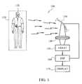
- FIG. 1diagrammatically illustrates an embodiment of the present invention
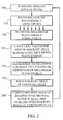
- FIG. 2provides a flowchart illustrating logic that may be used to implement a multi channel radiometer imaging system according to preferred embodiments of the present invention
- FIG. 3shows a conceptual view of an image generated by the present invention
- FIG. 4shows a conceptual view of a millimeter wave image generated in accordance with the present invention
- FIG. 5shows a conceptual view of a composite image formed in accordance with the present invention
- FIG. 6provides a block diagram of a pixel of the present invention.
- FIG. 7shows a conceptual view of a grid formed in accordance with the present invention.
- FIG. 8provides a conceptual view of a pixel in accordance with the present invention.
- FIG. 9shows a conceptual view of a sixteen pixel radiometer in accordance with the present invention.
- FIG. 10shows a conceptual view of a thirty-two pixel radiometer in accordance with the present invention.
- An imaging system 100is shown in accordance with the present invention.
- An imaging zone 110is formed by the area prescribed by scanning apparatus 130 that reflects millimeter wave energy 125 radiating from imaging zone 110 .
- Scanning apparatus 130is constrained to oscillate in a vertical plane to reflect millimeter wave energy 125 .
- Millimeter wave energy 125is reflected through an optical lens 140 to focus the millimeter wave energy 125 to an array of radiometers 150 .
- a digital signal processor 160correlates the movement of scanning apparatus 130 to specific x-y coordinates in the imaging zone 110 .
- algorithmsprocess the signals received by array 150 to form a composite image on display 170 showing the location of concealed objects on an individual 120 .
- FIG. 2shows a flow chart illustrating logic that may be used to implement preferred embodiments of the method of the present invention.
- imaging zoneis scanned 210 .
- millimeter wave energyis focused using optics 215 onto an array of pixels adapted to receive millimeter wave energy 220 .
- the array of pixelssends signals representing millimeter wave energy values to a CPU.
- Algorithmsprocess the signals, which recognize and calculate differences of millimeter wave energy 230 .
- a discrete image of contrast cellsis formed and a millimeter wave image is generated 235 .
- a real-time video image of imaging zone 110is overlaid by the respective discrete image of contrast cells forming a composite image showing the location of concealed objects on an individual 240 .
- a real-time video image of imaging zone 110is overlaid by the respective discrete image of contrast cells forming a composite image showing the location of concealed objects on an individual 240 .
- only the area of the millimeter wave image recognized as a possible location of a concealed object on an individualoverlays the real-time video image.
- FIG. 3shows a conceptual view of monitor 310 such that a real-time image 315 of an individual 120 is displayed.
- FIG. 4shows a conceptual view of individual 120 on monitor 410 representing a millimeter wave image 415 .
- a concealed object 115 on individual 120is displayed on monitor 410 , which is readily visible to security personnel. The location of concealed object 115 is determined by differences in millimeter wave energy received between individual 120 and the concealed object 115 .
- FIG. 5shows a conceptual view on monitor 510 with a composite image 515 formed by real-time video image 315 overlaid by millimeter wave image 415 .
- Composite image 515clearly shows the location of a concealed object 115 on individual 120 and circumscribed by box 530 .
- FIG. 6shows a block diagram of a pixel 600 of a millimeter wave radiometer in accordance with the present invention.
- An antennae 610is provided to receive millimeter wave energy.
- a RF switch 630is coupled between antennae 610 and radiometer receiver 650 thereby allowing receiver 650 to alternate between antenna 610 and a known reference load termination 620 .
- the signal from antennae 610is amplified by a single low noise amplifier 640 followed by a video amplifier 660 .
- the output of the video amplifier 660is used to produce an output voltage proportional to a difference between signal received by antenna 610 and the reference temperature to generate a millimeter wave pixel image for display 670 .
- a grid of discrete cells 700is shown. Each cell represents the millimeter wave energy received by a particular pixel that represents a specific x-y coordinate within the imaging zone 110 .
- Scene cells 725form the background for determining the contrast between millimeter wave energy emanating from the imaging zone 110 and individual 715 .
- the brightness of identification cells 730are used to define the outline of individual 715 within imaging zone 110 .
- Contrast cells 710are identified as those cells where the contrast between solid cells 730 is such that a concealed object is revealed. Once contrast cells 720 are determined, a box 720 is formed around the contrast cells for easy identification of the concealed object by security personnel.
- the sensitivity of the contrastis adjustable as determined by factors such as high or low ambient temperature.
- FIG. 8shows a pixel 800 of the radiometer in accordance with the present invention.
- a feedhorn 810is used as an antennae to receive millimeter wave energy.
- a MMIC 820 including a Dickey Switch followed by a single LNA per pixelis formed as part of pixel 800 .
- Pixel 800is adaptable to couple to an RF board known in the art.
- a focal plane array 920is formed by a plurality of pixels 800 . Each pixel is in electrical communication with RF board 910 and each pixel comprises a detection channel. For clarity, the housing and certain electrical components well known in the art are not shown.
- the array 920has two rows of pixels as the spacing of the pixels is limited by the size of the feedhorns. Offsetting the pixels in two rows reduces the line spacing between the center of the pixels to provide more resolution. In the preferred embodiment the offset is 1 ⁇ 2 pitch to effectively reduce the pixel spacing by a half in the horizontal direction.
- FIG. 10is a multi channel radiometer 950 in accordance with the present invention showing an expansion to thirty-two pixels in the focal plane array. Accordingly, the resolution of a millimeter wave is increased with the addition of pixels coupled to an RF board. A portion of housing 960 is shown to illustrate that radiometer 950 is enclosed to protect electrical components.
- each flow and/or block of the flow diagrams and/or block diagrams, and combinations of flows and/or blocks in the flow diagrams and/or block diagramscan be implemented by computer program instructions.
- These computer program instructionsmay be provided to a processor of a general purpose computer, special purpose computer, embedded processor, or other programmable data processing apparatus to produce a machine, such that the instructions, which execute via the processor of the computer or other programmable data processing apparatus, create means for implementing the functions specified in the flow diagram flow or flows and/or block diagram block or blocks.
Landscapes
- Physics & Mathematics (AREA)
- Life Sciences & Earth Sciences (AREA)
- General Life Sciences & Earth Sciences (AREA)
- General Physics & Mathematics (AREA)
- Geophysics (AREA)
- Radiation Pyrometers (AREA)
Abstract
Description
Claims (9)
Priority Applications (1)
| Application Number | Priority Date | Filing Date | Title |
|---|---|---|---|
| US13/540,340US8712093B2 (en) | 2007-08-08 | 2012-07-02 | Millimeter wave imaging method and system to detect concealed objects |
Applications Claiming Priority (2)
| Application Number | Priority Date | Filing Date | Title |
|---|---|---|---|
| US11/835,886US8213672B2 (en) | 2007-08-08 | 2007-08-08 | Millimeter wave imaging method and system to detect concealed objects |
| US13/540,340US8712093B2 (en) | 2007-08-08 | 2012-07-02 | Millimeter wave imaging method and system to detect concealed objects |
Related Parent Applications (1)
| Application Number | Title | Priority Date | Filing Date |
|---|---|---|---|
| US11/835,886ContinuationUS8213672B2 (en) | 2007-08-08 | 2007-08-08 | Millimeter wave imaging method and system to detect concealed objects |
Publications (2)
| Publication Number | Publication Date |
|---|---|
| US20120288137A1 US20120288137A1 (en) | 2012-11-15 |
| US8712093B2true US8712093B2 (en) | 2014-04-29 |
Family
ID=40346566
Family Applications (2)
| Application Number | Title | Priority Date | Filing Date |
|---|---|---|---|
| US11/835,886Expired - Fee RelatedUS8213672B2 (en) | 2007-08-08 | 2007-08-08 | Millimeter wave imaging method and system to detect concealed objects |
| US13/540,340Expired - Fee RelatedUS8712093B2 (en) | 2007-08-08 | 2012-07-02 | Millimeter wave imaging method and system to detect concealed objects |
Family Applications Before (1)
| Application Number | Title | Priority Date | Filing Date |
|---|---|---|---|
| US11/835,886Expired - Fee RelatedUS8213672B2 (en) | 2007-08-08 | 2007-08-08 | Millimeter wave imaging method and system to detect concealed objects |
Country Status (1)
| Country | Link |
|---|---|
| US (2) | US8213672B2 (en) |
Cited By (1)
| Publication number | Priority date | Publication date | Assignee | Title |
|---|---|---|---|---|
| CN106485077A (en)* | 2016-10-11 | 2017-03-08 | 深圳万发创新进出口贸易有限公司 | A kind of supervision place medical monitoring systems |
Families Citing this family (25)
| Publication number | Priority date | Publication date | Assignee | Title |
|---|---|---|---|---|
| US8213672B2 (en)* | 2007-08-08 | 2012-07-03 | Microsemi Corporation | Millimeter wave imaging method and system to detect concealed objects |
| US8421668B2 (en)* | 2008-04-21 | 2013-04-16 | Stalix Llc | Sub-millimeter wave RF and ultrasonic concealed object detection and identification |
| US20110084868A1 (en)* | 2009-10-08 | 2011-04-14 | Brijot Imaging Systems, Inc. | Variable range millimeter wave method and system |
| CN102313907B (en)* | 2010-06-30 | 2014-04-09 | 清华大学 | Millimeter wave inspection equipment |
| US20120026336A1 (en)* | 2010-07-29 | 2012-02-02 | Brijot Imaging Systems, Inc. | Method and system of enhanced integration of millimeter wave imagery |
| KR20120072048A (en)* | 2010-12-23 | 2012-07-03 | 한국전자통신연구원 | Apparatus of body measurement using millimeter-wave |
| US8903128B2 (en)* | 2011-02-16 | 2014-12-02 | Siemens Aktiengesellschaft | Object recognition for security screening and long range video surveillance |
| US10949677B2 (en) | 2011-03-29 | 2021-03-16 | Thermal Matrix USA, Inc. | Method and system for detecting concealed objects using handheld thermal imager |
| US12087142B2 (en) | 2011-03-29 | 2024-09-10 | Thermal Matrix USA, Inc. | Method and system for detecting concealed objects using handheld thermal imager |
| US20150181136A1 (en)* | 2011-03-29 | 2015-06-25 | Thermal Matrix USA, Inc. | Method and system for detecting concealed objects using handheld thermal imager |
| US8938114B2 (en)* | 2012-01-11 | 2015-01-20 | Sony Corporation | Imaging device and method for imaging hidden objects |
| CN103901490B (en)* | 2012-12-27 | 2017-02-08 | 同方威视技术股份有限公司 | Human body security check device and human body security check method |
| KR101538221B1 (en)* | 2013-09-23 | 2015-07-22 | 고려대학교 산학협력단 | Image sensing device using RF signal |
| US10416436B2 (en)* | 2016-04-11 | 2019-09-17 | Dante Duby | Advancements in reflective monocular, binocular, and night vision applications including multi-wave |
| US9869583B1 (en) | 2016-10-27 | 2018-01-16 | Northrop Grumman Systems Corporation | Image scanning on a sparsely populated focal plane array to achieve nyquist sampling |
| CN109521490B (en)* | 2018-11-12 | 2020-01-10 | 北京航空航天大学 | Millimeter wave array radiometer front end capable of realizing analog beam forming |
| CN109799544B (en)* | 2018-12-28 | 2021-03-19 | 深圳市重投华讯太赫兹科技有限公司 | Intelligent detection method and device applied to millimeter wave security check instrument and storage device |
| JP7170365B2 (en)* | 2019-07-16 | 2022-11-14 | ボディデータ インコーポレイテッド | Systems and methods for improving radar scanning coverage and efficiency |
| CN110443158B (en)* | 2019-07-18 | 2021-10-08 | 华中科技大学 | A Human Hidden Object Detection Method Based on Millimeter Wave Images |
| KR20210057516A (en) | 2019-11-12 | 2021-05-21 | 중앙대학교 산학협력단 | Symbol Recognition System and Method in Engineering Diagrams using Multi-Channel Data Augmentation |
| EP4176231A4 (en)* | 2020-09-15 | 2024-05-15 | Vayyar Imaging Ltd. | SYSTEMS AND METHODS FOR IMAGING A HIDDEN SURFACE |
| US20220107406A1 (en)* | 2020-10-05 | 2022-04-07 | Charles Partee | Combination optical and millimeter wavelength camera |
| US20250189662A1 (en)* | 2020-10-05 | 2025-06-12 | Syght, Inc. | Millimeter wavelength camera arrangement |
| DE102021202841A1 (en) | 2021-03-23 | 2022-09-29 | Fraunhofer-Gesellschaft zur Förderung der angewandten Forschung eingetragener Verein | Multi-channel catadioptric setup for recording an infrared image |
| CN113777605B (en)* | 2021-09-10 | 2024-06-18 | 哈尔滨工业大学 | A passive millimeter wave three-dimensional imaging system and imaging method thereof |
Citations (27)
| Publication number | Priority date | Publication date | Assignee | Title |
|---|---|---|---|---|
| US5379336A (en) | 1992-05-21 | 1995-01-03 | Hughes Aircraft Company | Hybridized semiconductor pixel detector arrays for use in digital radiography |
| US5606283A (en) | 1995-05-12 | 1997-02-25 | Trw Inc. | Monolithic multi-function balanced switch and phase shifter |
| US5821987A (en)* | 1992-06-23 | 1998-10-13 | Larson; Craig R. | Videophone for simultaneous audio and video communication via a standard telephone line |
| US5933120A (en) | 1996-12-16 | 1999-08-03 | Waveband Corporation | 2-D scanning antenna and method for the utilization thereof |
| US5982326A (en) | 1997-07-21 | 1999-11-09 | Chow; Yung Leonard | Active micropatch antenna device and array system |
| US6154174A (en) | 1999-04-20 | 2000-11-28 | General Atomics | Large aperture vibration compensated millimeter wave sensor |
| US20020044276A1 (en)* | 1998-08-05 | 2002-04-18 | Microvision, Inc. | Millimeter wave scanning imaging system |
| US20020090184A1 (en) | 2000-12-20 | 2002-07-11 | Michel Sayag | Light stimulating and collecting methods and apparatus for storage-phosphor image plates |
| US6677571B1 (en) | 2001-04-26 | 2004-01-13 | The United States Of America As Represented By The Secretary Of The Air Force | Rocket launch detection process |
| US20040057496A1 (en) | 2002-09-23 | 2004-03-25 | Raytheon Company | Radiometer with programmable noise source calibration |
| US20040066327A1 (en) | 2001-02-21 | 2004-04-08 | Salmon Neil A | Calibrating radiometers |
| US6777684B1 (en) | 1999-08-23 | 2004-08-17 | Rose Research L.L.C. | Systems and methods for millimeter and sub-millimeter wave imaging |
| US20050122254A1 (en) | 2003-09-18 | 2005-06-09 | Xytrans, Inc. | Multi-channel radiometer imaging system |
| US20050230604A1 (en) | 2004-04-14 | 2005-10-20 | Rowe Richard L | Multi-sensor surveillance portal |
| US20060088000A1 (en)* | 2004-10-27 | 2006-04-27 | Hans Hannu | Terminal having plural playback pointers for jitter buffer |
| US20060104480A1 (en)* | 2004-11-12 | 2006-05-18 | Safeview, Inc. | Active subject imaging with body identification |
| US7075080B2 (en) | 2003-01-31 | 2006-07-11 | Millivision Technologies | Offset drift compensating flat fielding method and camera used in millimeter wave imaging |
| US20060164064A1 (en) | 2003-09-18 | 2006-07-27 | Xytrans, Inc. | Multi-channel radiometer imaging system |
| US7132649B2 (en) | 2003-01-31 | 2006-11-07 | Vaidya Nitin M | Weighted noise compensating method and camera used in millimeter wave imaging |
| US20070001895A1 (en)* | 2003-08-12 | 2007-01-04 | Trex Enterprises | Multi-channel millimeter wave imaging system |
| US20070080850A1 (en)* | 2003-09-11 | 2007-04-12 | Kyoichi Abe | Object detection system and object detection method |
| US20070232222A1 (en)* | 2006-03-29 | 2007-10-04 | De Jong Dick | Method and system for managing audio data |
| US20090041293A1 (en) | 2007-08-08 | 2009-02-12 | Brian Andrew | Multiple camera imaging method and system for detecting concealed objects |
| US20090041292A1 (en) | 2007-08-08 | 2009-02-12 | Robert Daly | Multi channel radiometer imaging method and system |
| US20090060272A1 (en) | 2007-06-20 | 2009-03-05 | Reinpoldt Iii Willem H | System and method for overlaying computer generated highlights in a display of millimeter wave imagery |
| US20090251355A1 (en) | 2006-06-30 | 2009-10-08 | Toyota Jidosha Kabushiki Kaisha | Automotive drive assist system with sensor fusion of radar and camera and probability estimation of object existence for varying a threshold in the radar |
| US20100306701A1 (en)* | 2009-05-29 | 2010-12-02 | Sean Glen | Creation, Previsualization, Communication, and Documentation of Choreographed Movement |
- 2007
- 2007-08-08USUS11/835,886patent/US8213672B2/ennot_activeExpired - Fee Related
- 2012
- 2012-07-02USUS13/540,340patent/US8712093B2/ennot_activeExpired - Fee Related
Patent Citations (34)
| Publication number | Priority date | Publication date | Assignee | Title |
|---|---|---|---|---|
| US5379336A (en) | 1992-05-21 | 1995-01-03 | Hughes Aircraft Company | Hybridized semiconductor pixel detector arrays for use in digital radiography |
| US5821987A (en)* | 1992-06-23 | 1998-10-13 | Larson; Craig R. | Videophone for simultaneous audio and video communication via a standard telephone line |
| US5606283A (en) | 1995-05-12 | 1997-02-25 | Trw Inc. | Monolithic multi-function balanced switch and phase shifter |
| US5933120A (en) | 1996-12-16 | 1999-08-03 | Waveband Corporation | 2-D scanning antenna and method for the utilization thereof |
| US5982326A (en) | 1997-07-21 | 1999-11-09 | Chow; Yung Leonard | Active micropatch antenna device and array system |
| US20020044276A1 (en)* | 1998-08-05 | 2002-04-18 | Microvision, Inc. | Millimeter wave scanning imaging system |
| US6154174A (en) | 1999-04-20 | 2000-11-28 | General Atomics | Large aperture vibration compensated millimeter wave sensor |
| US6777684B1 (en) | 1999-08-23 | 2004-08-17 | Rose Research L.L.C. | Systems and methods for millimeter and sub-millimeter wave imaging |
| US20020090184A1 (en) | 2000-12-20 | 2002-07-11 | Michel Sayag | Light stimulating and collecting methods and apparatus for storage-phosphor image plates |
| US6900756B2 (en) | 2001-02-21 | 2005-05-31 | Qinetiq Limited | Calibrating radiometers |
| US20040066327A1 (en) | 2001-02-21 | 2004-04-08 | Salmon Neil A | Calibrating radiometers |
| US6677571B1 (en) | 2001-04-26 | 2004-01-13 | The United States Of America As Represented By The Secretary Of The Air Force | Rocket launch detection process |
| US6834991B2 (en) | 2002-09-23 | 2004-12-28 | Raytheon Company | Radiometer with programmable noise source calibration |
| US20040057496A1 (en) | 2002-09-23 | 2004-03-25 | Raytheon Company | Radiometer with programmable noise source calibration |
| US7075080B2 (en) | 2003-01-31 | 2006-07-11 | Millivision Technologies | Offset drift compensating flat fielding method and camera used in millimeter wave imaging |
| US7132649B2 (en) | 2003-01-31 | 2006-11-07 | Vaidya Nitin M | Weighted noise compensating method and camera used in millimeter wave imaging |
| US20070001895A1 (en)* | 2003-08-12 | 2007-01-04 | Trex Enterprises | Multi-channel millimeter wave imaging system |
| US20070080850A1 (en)* | 2003-09-11 | 2007-04-12 | Kyoichi Abe | Object detection system and object detection method |
| US20060164064A1 (en) | 2003-09-18 | 2006-07-27 | Xytrans, Inc. | Multi-channel radiometer imaging system |
| US7088086B2 (en) | 2003-09-18 | 2006-08-08 | Xytrans, Inc. | Multi-channel radiometer imaging system |
| US20050122254A1 (en) | 2003-09-18 | 2005-06-09 | Xytrans, Inc. | Multi-channel radiometer imaging system |
| US7239122B2 (en) | 2003-09-18 | 2007-07-03 | Xytrans, Inc. | Multi-channel radiometer imaging system |
| US20050230604A1 (en) | 2004-04-14 | 2005-10-20 | Rowe Richard L | Multi-sensor surveillance portal |
| US7180441B2 (en) | 2004-04-14 | 2007-02-20 | Safeview, Inc. | Multi-sensor surveillance portal |
| US20060088000A1 (en)* | 2004-10-27 | 2006-04-27 | Hans Hannu | Terminal having plural playback pointers for jitter buffer |
| US20060104480A1 (en)* | 2004-11-12 | 2006-05-18 | Safeview, Inc. | Active subject imaging with body identification |
| US20070232222A1 (en)* | 2006-03-29 | 2007-10-04 | De Jong Dick | Method and system for managing audio data |
| US20090251355A1 (en) | 2006-06-30 | 2009-10-08 | Toyota Jidosha Kabushiki Kaisha | Automotive drive assist system with sensor fusion of radar and camera and probability estimation of object existence for varying a threshold in the radar |
| US20090060272A1 (en) | 2007-06-20 | 2009-03-05 | Reinpoldt Iii Willem H | System and method for overlaying computer generated highlights in a display of millimeter wave imagery |
| US20090041293A1 (en) | 2007-08-08 | 2009-02-12 | Brian Andrew | Multiple camera imaging method and system for detecting concealed objects |
| US20090041292A1 (en) | 2007-08-08 | 2009-02-12 | Robert Daly | Multi channel radiometer imaging method and system |
| US7873182B2 (en) | 2007-08-08 | 2011-01-18 | Brijot Imaging Systems, Inc. | Multiple camera imaging method and system for detecting concealed objects |
| US8213672B2 (en)* | 2007-08-08 | 2012-07-03 | Microsemi Corporation | Millimeter wave imaging method and system to detect concealed objects |
| US20100306701A1 (en)* | 2009-05-29 | 2010-12-02 | Sean Glen | Creation, Previsualization, Communication, and Documentation of Choreographed Movement |
Non-Patent Citations (1)
| Title |
|---|
| Sheen et al., "Three-Dimensional Millimeter Wave Imaging for Concealed Weapon Detection," IEEE transaction on Microwave Theory and Techniques, vol. 49, No. 9, Sep. 2001, pp. 1581-1592. |
Cited By (2)
| Publication number | Priority date | Publication date | Assignee | Title |
|---|---|---|---|---|
| CN106485077A (en)* | 2016-10-11 | 2017-03-08 | 深圳万发创新进出口贸易有限公司 | A kind of supervision place medical monitoring systems |
| CN106485077B (en)* | 2016-10-11 | 2018-12-14 | 徐州玖胜医疗器械有限公司 | A kind of supervision place medical monitoring systems |
Also Published As
| Publication number | Publication date |
|---|---|
| US8213672B2 (en) | 2012-07-03 |
| US20120288137A1 (en) | 2012-11-15 |
| US20090041292A1 (en) | 2009-02-12 |
Similar Documents
| Publication | Publication Date | Title |
|---|---|---|
| US8712093B2 (en) | Millimeter wave imaging method and system to detect concealed objects | |
| US11002777B2 (en) | Microwave sensor using rydberg particles | |
| US7499583B2 (en) | Optical inspection method for substrate defect detection | |
| US9891314B2 (en) | Ultra wide band detectors | |
| EP1654560B1 (en) | Security system with mm-wave imaging | |
| US20050093733A1 (en) | Security system with metal detection and mm-wave imaging | |
| US20070139248A1 (en) | System and method for standoff microwave imaging | |
| CN109696299B (en) | Terahertz focal plane imaging system comprehensive research and development platform | |
| MXPA03004979A (en) | Off-center tomosynthesis. | |
| Jain et al. | Terahertz light-field imaging | |
| TWI447403B (en) | Display apparatus and method for real-time radiation pattern visualization | |
| US20190227190A1 (en) | System and method for debugging millimeter wave security inspection instrument | |
| Wright et al. | The supernova remnant Cassiopeia A at millimeter wavelengths | |
| US6365425B1 (en) | Method of manufacturing semiconductor device | |
| Ritacco et al. | Absolute reference for microwave polarization experiments. the cosmocal project and its proof of concept | |
| JP2010044026A (en) | Apparatus for visualizing radio wave source | |
| CN211718540U (en) | Dual-polarization detection terahertz safety inspection device | |
| RU2154284C1 (en) | Method for passive, non-scanning, multiple-spectrum, omnibearing and/or coordinate finding and television device implementing it | |
| Enayati et al. | THz holographic imaging: A spatial-domain technique for phase retrieval and image reconstruction | |
| Dallinger et al. | Millimeter-wave imaging of humans-basic experiments | |
| US20250189693A1 (en) | Terahertz signal-based image collection device, image generation system and image generation method | |
| US20090040092A1 (en) | Broadband energy illuminator | |
| Dallinger et al. | Short distance related security millimeter-wave imaging systems | |
| Schreiber et al. | First design investigations on a fully-electronic microwave imaging radiometer system | |
| CN118671025A (en) | Terahertz wave beam scanning imaging system and scanning imaging method |
Legal Events
| Date | Code | Title | Description |
|---|---|---|---|
| AS | Assignment | Owner name:MORGAN STANLEY SENIOR FUNDING, INC., NEW YORK Free format text:PATENT SECURITY AGREEMENT;ASSIGNORS:MICROSEMI CORPORATION;MICROSEMI SEMICONDUCTOR (U.S.) INC. (F/K/A LEGERITY, INC., ZARLINK SEMICONDUCTOR (V.N.) INC., CENTELLAX, INC., AND ZARLINK SEMICONDUCTOR (U.S.) INC.);MICROSEMI FREQUENCY AND TIME CORPORATION (F/K/A SYMMETRICON, INC.);AND OTHERS;REEL/FRAME:037691/0697 Effective date:20160115 | |
| FEPP | Fee payment procedure | Free format text:MAINTENANCE FEE REMINDER MAILED (ORIGINAL EVENT CODE: REM.) | |
| LAPS | Lapse for failure to pay maintenance fees | Free format text:PATENT EXPIRED FOR FAILURE TO PAY MAINTENANCE FEES (ORIGINAL EVENT CODE: EXP.) | |
| STCH | Information on status: patent discontinuation | Free format text:PATENT EXPIRED DUE TO NONPAYMENT OF MAINTENANCE FEES UNDER 37 CFR 1.362 | |
| AS | Assignment | Owner name:MICROSEMI FREQUENCY AND TIME CORPORATION, CALIFORN Free format text:RELEASE BY SECURED PARTY;ASSIGNOR:MORGAN STANLEY SENIOR FUNDING, INC.;REEL/FRAME:046251/0391 Effective date:20180529 Owner name:MICROSEMI COMMUNICATIONS, INC., CALIFORNIA Free format text:RELEASE BY SECURED PARTY;ASSIGNOR:MORGAN STANLEY SENIOR FUNDING, INC.;REEL/FRAME:046251/0391 Effective date:20180529 Owner name:MICROSEMI CORP. - POWER PRODUCTS GROUP, CALIFORNIA Free format text:RELEASE BY SECURED PARTY;ASSIGNOR:MORGAN STANLEY SENIOR FUNDING, INC.;REEL/FRAME:046251/0391 Effective date:20180529 Owner name:MICROSEMI SEMICONDUCTOR (U.S.), INC., CALIFORNIA Free format text:RELEASE BY SECURED PARTY;ASSIGNOR:MORGAN STANLEY SENIOR FUNDING, INC.;REEL/FRAME:046251/0391 Effective date:20180529 Owner name:MICROSEMI CORPORATION, CALIFORNIA Free format text:RELEASE BY SECURED PARTY;ASSIGNOR:MORGAN STANLEY SENIOR FUNDING, INC.;REEL/FRAME:046251/0391 Effective date:20180529 Owner name:MICROSEMI CORP. - RF INTEGRATED SOLUTIONS, CALIFOR Free format text:RELEASE BY SECURED PARTY;ASSIGNOR:MORGAN STANLEY SENIOR FUNDING, INC.;REEL/FRAME:046251/0391 Effective date:20180529 Owner name:MICROSEMI SOC CORP., CALIFORNIA Free format text:RELEASE BY SECURED PARTY;ASSIGNOR:MORGAN STANLEY SENIOR FUNDING, INC.;REEL/FRAME:046251/0391 Effective date:20180529 | |
| FP | Expired due to failure to pay maintenance fee | Effective date:20180429 |