US8711760B2 - Method and apparatus to adjust received signal - Google Patents
Method and apparatus to adjust received signalDownload PDFInfo
- Publication number
- US8711760B2 US8711760B2US12/732,459US73245910AUS8711760B2US 8711760 B2US8711760 B2US 8711760B2US 73245910 AUS73245910 AUS 73245910AUS 8711760 B2US8711760 B2US 8711760B2
- Authority
- US
- United States
- Prior art keywords
- evm
- transmitter
- value
- deviation
- mimo
- Prior art date
- Legal status (The legal status is an assumption and is not a legal conclusion. Google has not performed a legal analysis and makes no representation as to the accuracy of the status listed.)
- Expired - Fee Related, expires
Links
- 238000000034methodMethods0.000titleclaimsabstractdescription22
- 238000007476Maximum LikelihoodMethods0.000claimsabstractdescription32
- 238000004891communicationMethods0.000claimsabstractdescription20
- 230000005540biological transmissionEffects0.000claimsdescription15
- 230000015654memoryEffects0.000claimsdescription7
- 238000001514detection methodMethods0.000claimsdescription6
- 238000010586diagramMethods0.000description7
- 239000011159matrix materialSubstances0.000description6
- 230000010363phase shiftEffects0.000description3
- 238000001228spectrumMethods0.000description3
- 230000008901benefitEffects0.000description2
- 238000012986modificationMethods0.000description2
- 230000004048modificationEffects0.000description2
- 238000012545processingMethods0.000description2
- 230000009471actionEffects0.000description1
- 239000000654additiveSubstances0.000description1
- 230000000996additive effectEffects0.000description1
- 230000015556catabolic processEffects0.000description1
- 230000000295complement effectEffects0.000description1
- 125000004122cyclic groupChemical group0.000description1
- 238000006731degradation reactionMethods0.000description1
- 238000013178mathematical modelMethods0.000description1
- 238000005259measurementMethods0.000description1
- 230000008520organizationEffects0.000description1
- 230000008569processEffects0.000description1
- 238000005070samplingMethods0.000description1
- 230000007480spreadingEffects0.000description1
- 239000000126substanceSubstances0.000description1
- 238000006467substitution reactionMethods0.000description1
- 230000007704transitionEffects0.000description1
Images


Classifications
- H—ELECTRICITY
- H04—ELECTRIC COMMUNICATION TECHNIQUE
- H04L—TRANSMISSION OF DIGITAL INFORMATION, e.g. TELEGRAPHIC COMMUNICATION
- H04L1/00—Arrangements for detecting or preventing errors in the information received
- H04L1/0001—Systems modifying transmission characteristics according to link quality, e.g. power backoff
- H04L1/0023—Systems modifying transmission characteristics according to link quality, e.g. power backoff characterised by the signalling
- H04L1/0026—Transmission of channel quality indication
- H—ELECTRICITY
- H04—ELECTRIC COMMUNICATION TECHNIQUE
- H04L—TRANSMISSION OF DIGITAL INFORMATION, e.g. TELEGRAPHIC COMMUNICATION
- H04L25/00—Baseband systems
- H04L25/02—Details ; arrangements for supplying electrical power along data transmission lines
- H04L25/03—Shaping networks in transmitter or receiver, e.g. adaptive shaping networks
- H04L25/03891—Spatial equalizers
- H—ELECTRICITY
- H04—ELECTRIC COMMUNICATION TECHNIQUE
- H04L—TRANSMISSION OF DIGITAL INFORMATION, e.g. TELEGRAPHIC COMMUNICATION
- H04L5/00—Arrangements affording multiple use of the transmission path
- H04L5/0001—Arrangements for dividing the transmission path
- H04L5/0014—Three-dimensional division
- H04L5/0023—Time-frequency-space
- H—ELECTRICITY
- H04—ELECTRIC COMMUNICATION TECHNIQUE
- H04B—TRANSMISSION
- H04B7/00—Radio transmission systems, i.e. using radiation field
- H04B7/02—Diversity systems; Multi-antenna system, i.e. transmission or reception using multiple antennas
- H04B7/04—Diversity systems; Multi-antenna system, i.e. transmission or reception using multiple antennas using two or more spaced independent antennas
- H04B7/0413—MIMO systems
- H—ELECTRICITY
- H04—ELECTRIC COMMUNICATION TECHNIQUE
- H04L—TRANSMISSION OF DIGITAL INFORMATION, e.g. TELEGRAPHIC COMMUNICATION
- H04L1/00—Arrangements for detecting or preventing errors in the information received
- H04L1/20—Arrangements for detecting or preventing errors in the information received using signal quality detector
- H—ELECTRICITY
- H04—ELECTRIC COMMUNICATION TECHNIQUE
- H04L—TRANSMISSION OF DIGITAL INFORMATION, e.g. TELEGRAPHIC COMMUNICATION
- H04L25/00—Baseband systems
- H04L25/02—Details ; arrangements for supplying electrical power along data transmission lines
- H04L25/03—Shaping networks in transmitter or receiver, e.g. adaptive shaping networks
- H04L25/03006—Arrangements for removing intersymbol interference
- H04L2025/0335—Arrangements for removing intersymbol interference characterised by the type of transmission
- H04L2025/03426—Arrangements for removing intersymbol interference characterised by the type of transmission transmission using multiple-input and multiple-output channels
- H—ELECTRICITY
- H04—ELECTRIC COMMUNICATION TECHNIQUE
- H04L—TRANSMISSION OF DIGITAL INFORMATION, e.g. TELEGRAPHIC COMMUNICATION
- H04L25/00—Baseband systems
- H04L25/02—Details ; arrangements for supplying electrical power along data transmission lines
- H04L25/03—Shaping networks in transmitter or receiver, e.g. adaptive shaping networks
- H04L25/03006—Arrangements for removing intersymbol interference
- H04L25/03343—Arrangements at the transmitter end
- H—ELECTRICITY
- H04—ELECTRIC COMMUNICATION TECHNIQUE
- H04L—TRANSMISSION OF DIGITAL INFORMATION, e.g. TELEGRAPHIC COMMUNICATION
- H04L5/00—Arrangements affording multiple use of the transmission path
- H04L5/0091—Signalling for the administration of the divided path, e.g. signalling of configuration information
- H—ELECTRICITY
- H04—ELECTRIC COMMUNICATION TECHNIQUE
- H04W—WIRELESS COMMUNICATION NETWORKS
- H04W52/00—Power management, e.g. Transmission Power Control [TPC] or power classes
- H04W52/04—Transmission power control [TPC]
- H04W52/18—TPC being performed according to specific parameters
- H04W52/22—TPC being performed according to specific parameters taking into account previous information or commands
- H04W52/226—TPC being performed according to specific parameters taking into account previous information or commands using past references to control power, e.g. look-up-table
- H—ELECTRICITY
- H04—ELECTRIC COMMUNICATION TECHNIQUE
- H04W—WIRELESS COMMUNICATION NETWORKS
- H04W52/00—Power management, e.g. Transmission Power Control [TPC] or power classes
- H04W52/04—Transmission power control [TPC]
- H04W52/18—TPC being performed according to specific parameters
- H04W52/24—TPC being performed according to specific parameters using SIR [Signal to Interference Ratio] or other wireless path parameters
- H04W52/241—TPC being performed according to specific parameters using SIR [Signal to Interference Ratio] or other wireless path parameters taking into account channel quality metrics, e.g. SIR, SNR, CIR or Eb/lo
Definitions
- Wireless local area network (WLAN) devicesmay include a Multiple-Input-Multiple-Output (MIMO) transmitter receiver system.
- MIMOMultiple-Input-Multiple-Output
- a Maximum Likelihood (ML) MIMO receivermay not know the transmitter Error Vector Magnitude (EVM). This may result degradation at the performance of the ML receiver, at least but not limited to, the 3 ⁇ 3 and higher MIMO modulations.
- EVMError Vector Magnitude
- a problem with a MIMO communicationmay be as follows (the following is a simplified model): a transmitter of the MIMO may transmit a vector x. Each element in the vector is a member of a set of a (linear) digital modulation such as, for example a Binary Phase Shift Keying (BPSK), Quadrature Phase Shift Keying (QPSK), 16-Quadrature amplitude modulation (QAM), 64-QAM or the like.
- BPSKBinary Phase Shift Keying
- QPSKQuadrature Phase Shift Keying
- QAM16-Quadrature amplitude modulation
- 64-QAM64-QAM or the like.
- a receiver of the MIMOis able to receive a set of receive channels y.
- the transmitted vector xpasses through a matrix representing a channel H.
- the matrix Hincludes a plurality of rows k and a plurality of columns l. Each element in the row k and the column l represents the channel between the l' th transmit antenna to the k'th receive chain.
- x ⁇arg x ⁇ min ⁇ 1 ( 2 ⁇ ⁇ ) k / 2 ⁇ ⁇ k ⁇ exp ⁇ ( 1 2 ⁇ ⁇ 2 ⁇ ( y - Hx ) H ⁇ ( y - Hx ) ) .
- the model described aboveignores the transmitter noise which is mostly generated from phase noise and power amplifier non-linearity.
- the disregard for the transmitter noisemay cause the ML receiver to place the transmitted constellation point on an error constellation point of a constellation diagram.
- the noise at the receiveris colored and the maximum likelihood search is depicted as
- R nis the combined noise covariance matrix at the ML receiver (for example Gaussian noise of the transmitter).
- R n⁇ R 2 I+ ⁇ T 2 HH H
- ⁇ R 2is the noise variance at each of the receiver chains, as measured at the receiver
- ⁇ T 2is the transmitter noise variance, as measured at the transmitter antenna ports.
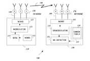
- FIG. 1is a schematic illustration of a wireless communication system according to exemplary embodiments of the present invention
- FIG. 2is a schematic illustration of a packet according to exemplary embodiment of the invention.
- FIG. 3is a flow chart of a method of transmitting EVM deviation value at a wireless communication device according to some embodiments of the present invention.
- FIG. 4is a flow chart of a method of receiving a constellation of data streams to some embodiments of the invention.
- the term EVM(which may be also called receive/transmit constellation error (RCE)) may be defined as a measure used to quantify the performance of the transmitter and/or receiver.
- the EVM measuremay provide an indication of how far transmitter constellation points are from the ideal locations when representing a transmit signal without noise and/or distortion.
- An ideal transmitter EVMmay be measured at the factory and may be stored in a memory for use with embodiment of the invention.
- An error vectoris a vector in the In-phase-Quadrature-phase (I-Q) plane between the ideal constellation point and the point received by the receiver. In other words, it is the difference between actual received symbols and ideal symbols.
- the average power of the error vector, normalized to signal power,is the EVM.
- EVMas defined for multi carrier modulations, is a ratio of two mean powers and is insensitive to the constellation geometry.
- the EVMmay be related to modulation error ratio, the ratio of mean signal power to mean error power.
- a constellation diagramis a representation of a signal modulated by a digital modulation scheme such as, for example a quadrature amplitude modulation, a phase-shift keying or the like.
- the constellation diagrammay display the transmitted signal as a two-dimensional scatter diagram in the complex plane at symbol sampling instants.
- constellation diagramsmay be used to recognize the type of interference and distortion in the transmitter signal, if desired.
- maximum likelihood detection upon reception of the transmitted signalsmay be used.
- a demodulatormay examine a received symbol, which may have been corrupted by a channel and/or a receiver noise.
- the corruptionmay be caused, for example, by an additive white Gaussian noise, a distortion, a phase noise an interference or the like.
- the demodulatormay estimate a point on the constellation diagram which is closest to that of the received symbol in order to detect what was actually transmitted.
- the receivermay adjust the received signal according to the transmitter EVM deviation value, if desired.
- a Gaussian noiseis shown as fuzzy constellation points
- a Non-coherent single frequency interferenceis shown as circular constellation points
- a Phase noiseis shown as rotationally spreading constellation points, although the scope of the present invention is not limited in this respect.
- Types of WLAN stationsintended to be within the scope of the present invention include, although are not limited to, mobile stations, access points, stations for receiving and transmitting spread spectrum signals such as, for example, Frequency Hopping Spread Spectrum (FHSS), Direct Sequence Spread Spectrum (DSSS), Complementary Code Keying (CCK), Orthogonal Frequency-Division Multiplexing (OFDM) and the like.
- FHSSFrequency Hopping Spread Spectrum
- DSSSDirect Sequence Spread Spectrum
- CKComplementary Code Keying
- OFDMOrthogonal Frequency-Division Multiplexing
- wireless communication system 100may employ a WLAN.
- WLAN 100may operate according to the standard developing by the IEEE 802.11.ac or the like.
- WLAN 100may include, but is not limited to including, a multiple-input-multiple-output (MIMO) transmitter 110 , and MIMO receiver 150 .
- MIMO transmitter 110may include noise estimator 111 , an EVM deviation value generator 113 , a modulator 115 , a MIMO 117 , antennas 120 which receive a transmitter noise 130 .
- MIMO receiver 150may include a maximum likelihood (ML) detector 151 , a demodulator 157 , a calibration error table 157 , a MIMO 155 , antennas 160 which may receive noise 170 .
- MLmaximum likelihood
- antennas 120may include three ( 3 ) antennas and antennas 160 may include three ( 3 ) antennas.
- the antennasmay be dipole antennas, internal antennas, Yagi antennas, an antenna array or the like.
- MIMO transmitter 110may estimate a transition noise (e.g., TX noise 130 ) by noise estimator 111 .
- EVM deviation value generator 113may calculate an EVM deviation value by, for example, submitting the noise estimate from a pre-stored noise measure.
- the pre-stored noise measurementmay be stored in a table similar to error table 158 (not shown), if desired.
- EVM deviation value generator 113may generate a frame and/or data packets which include the EVM deviation value.
- modulator 115may be an Orthogonal Frequency Division Multiplexing (OFDM) modulator and/or Orthogonal Frequency Division Multiple Access (OFDMA) modulator or the like.
- Modulator 115may modulate the data packet to a transmission vector x wherein each element in the vector x be a member of a set of a (linear) digital modulation such as, for example, a BPSK, QPSK, 16-QAM, 64-QAM or the like.
- MIMO 117may transmit the vector x by antennas 120 over channel H 140 .
- antennas 160may receive the transmitted signal with additional receive (RX) noise 170 .
- the received signalmay include at least the data packet which includes the EVM deviation value, if desired.
- MIMO receivers 155may receive the received signal.
- Demodulator 153may demodulate the received signal and may provide symbols of the data packet.
- x ⁇arg x ⁇ min ⁇ ⁇ R - 1 2 ⁇ r - R - 1 2 ⁇ Hx ⁇ 2 , although the scope of the present invention is not limited in this respect.
- ML detector 151is operably coupled to memory 157 which may store exemplary table 1 below.
- Table 1may be presorted in memory 157 during a device calibration for example in a factory.
- Exemplary Table 1shows the allowed relative constellation error versus constellation size and coding rate, if desired.
- ML detector 151may receive the EVM deviation value and may add it to the relative constellation error value stored in table 1, although the scope of the present invention is not limited to this example.
- ML detector 151may estimate ⁇ T 2 (e.g. transmitter noise) using the EVM, although the scope of the present invention is not limited to this example.
- FIG. 2a schematic illustration of a frame 200 according to exemplary embodiment of the invention is shown.
- frame 200may include Modulation and Coding Scheme (MCS) field 201 that include 8 bits, a coding field 203 that include 1 bit, an EVE field 204 which include the EVM deviation value of 3 bits, Reserve field 206 , Cyclic Redundancy Check (CRC) field of 4 bits for checking errors in the frame and a tail field 209 of 6 bits, although it should be understood that this frame is an example only and other frames with other data may be used with embodiments of the invention.
- MCSModulation and Coding Scheme
- a MIMO transmittere.g., transmitter 110
- the transmittermay measure a noise level value indicating a quality of the noise level.
- the transmittermay transmit the noise level value indicating a quality of the noise level in relation to a required noise level for a transmitted constellation of data streams.
- the MIMO transmittermay measure before each transmission a transmission noise (e.g., TX noise 130 ) as shown at text box 310 .
- the transmittermay calculate EVM deviation value by, for example, comparing the measured noise to a stored noise values (text box 320 ), if desired.
- the transmittermay enter the calculated EVM deviation value to a frame field (e.g., EVM field 204 ) and transmitted the frame to a ML MIMO receiver e.g., receiver 150 (text box 330 ).
- the EVM deviation valueis transmitted in each transmission to the ML MIMO receiver in order to correct error in the signal which caused by the noise and/or to filter the noise.
- the noisemay be a white noise a Gaussian noise or the like.
- FIG. 4a flow chart of a method of receiving a constellation of data streams to some embodiments of the invention is shown.
- the methodstarts with receiving signals using a LM MIMO receiver (text box 410 ).
- the signalsmay be OFDM signals and may include data packets which include frames.
- the ML MIMO receivere.g. receiver 150
- the ML MIMO receivermay decode from the received signal the frame which include the EVM deviation value (text box 420 ).
- the ML MIMO decodermay adjust the received signals according to the transmitter EVM (text box 430 ) for example, by receiving a Modulation and Coding Scheme (MCS) (e.g., field 201 ) and adding the EVM deviation value to a pre-stored EVM value according to the MCS for placing a detected symbol on a desired constellation point, if desired.
- MCSModulation and Coding Scheme
- the ML MIMO receivermay perform ML detection and/or search on the received frame in order to detect data symbols (text box 440 ).
- the constellation point values and/or error valuesmay be stored in a table such as, for example table 1 above.
- the result of the methodis detection without errors the symbols of the received data packet which may enable the transmitter to transmit at a faster data rate and/or less robust modulation schemes, although other advantage may be achieved by using embodiment of the invention.
Landscapes
- Engineering & Computer Science (AREA)
- Signal Processing (AREA)
- Computer Networks & Wireless Communication (AREA)
- Quality & Reliability (AREA)
- Power Engineering (AREA)
- Radio Transmission System (AREA)
- Noise Elimination (AREA)
- Transmitters (AREA)
- Digital Transmission Methods That Use Modulated Carrier Waves (AREA)
- Detection And Prevention Of Errors In Transmission (AREA)
Abstract
Description
This is equivalent to {circumflex over (x)}=argxmin∥y−Hx∥.
Where Rnis the combined noise covariance matrix at the ML receiver (for example Gaussian noise of the transmitter). Rn=σR2I+σT2HHHwhere, σR2is the noise variance at each of the receiver chains, as measured at the receiver and σT2is the transmitter noise variance, as measured at the transmitter antenna ports. While H is estimated during packet preamble analysis at the ML receiver, the ratio between σR2and σT2is not known to the ML receiver and may impair the ML receiver performance. Thus, there is a need to mitigate the above described problems.
although the scope of the present invention is not limited in this respect.
| TABLE 1 | ||
| Modulation | Coding Rate | Relative constellation error (dB) |
| BPSK | ½ | −5 |
| QPSK | ½ | −10 |
| QPSK | ¾ | −13 |
| 16-QAM | ½ | −16 |
| 16-QAM | ¾ | −19 |
| 64-QAM | ⅔ | −22 |
| 64-QAM | ¾ | −25 |
| 64-QAM | ⅚ | −28 |
| 256-QAM | ⅔ | −28 |
| 256-QAM | ¾ | −31 |
| 256-QAM | ⅚ | −34 |
Claims (19)
Priority Applications (5)
| Application Number | Priority Date | Filing Date | Title |
|---|---|---|---|
| US12/732,459US8711760B2 (en) | 2010-03-26 | 2010-03-26 | Method and apparatus to adjust received signal |
| JP2011034593AJP5182679B2 (en) | 2010-03-26 | 2011-02-21 | Method and apparatus for adjusting a received signal |
| CN2011100821724ACN102201850A (en) | 2010-03-26 | 2011-03-25 | Method and apparatus to adjust received signal |
| PCT/US2011/030117WO2011120031A2 (en) | 2010-03-26 | 2011-03-26 | Method and apparatus to adjust received signal |
| EP11760365.4AEP2553833B1 (en) | 2010-03-26 | 2011-03-26 | Method and apparatus to adjust received signal |
Applications Claiming Priority (1)
| Application Number | Priority Date | Filing Date | Title |
|---|---|---|---|
| US12/732,459US8711760B2 (en) | 2010-03-26 | 2010-03-26 | Method and apparatus to adjust received signal |
Publications (2)
| Publication Number | Publication Date |
|---|---|
| US20110235622A1 US20110235622A1 (en) | 2011-09-29 |
| US8711760B2true US8711760B2 (en) | 2014-04-29 |
Family
ID=44656429
Family Applications (1)
| Application Number | Title | Priority Date | Filing Date |
|---|---|---|---|
| US12/732,459Expired - Fee RelatedUS8711760B2 (en) | 2010-03-26 | 2010-03-26 | Method and apparatus to adjust received signal |
Country Status (5)
| Country | Link |
|---|---|
| US (1) | US8711760B2 (en) |
| EP (1) | EP2553833B1 (en) |
| JP (1) | JP5182679B2 (en) |
| CN (1) | CN102201850A (en) |
| WO (1) | WO2011120031A2 (en) |
Cited By (3)
| Publication number | Priority date | Publication date | Assignee | Title |
|---|---|---|---|---|
| US9602176B2 (en) | 2010-10-01 | 2017-03-21 | Commscope Technologies Llc | Distributed antenna system for MIMO signals |
| US9787385B2 (en) | 2009-12-09 | 2017-10-10 | Andrew Wireless Systems Gmbh | Distributed antenna system for MIMO signals |
| US20210167904A1 (en)* | 2019-12-03 | 2021-06-03 | Telefonaktiebolaget Lm Ericsson (Publ) | Evm for pulse-shaped signaling for high frequency radio networks |
Families Citing this family (13)
| Publication number | Priority date | Publication date | Assignee | Title |
|---|---|---|---|---|
| US8711760B2 (en)* | 2010-03-26 | 2014-04-29 | Intel Corporation | Method and apparatus to adjust received signal |
| JP6050625B2 (en)* | 2012-06-28 | 2016-12-21 | サターン ライセンシング エルエルシーSaturn Licensing LLC | Information processing apparatus and information processing method, computer program, and information communication system |
| CN105284062A (en)* | 2013-09-26 | 2016-01-27 | 华为技术有限公司 | Signal sending and receiving method, apparatus and system |
| CN104954086B (en)* | 2014-03-31 | 2018-08-07 | 电信科学技术研究院 | A kind of signal detecting method and device |
| US10889501B2 (en) | 2016-02-24 | 2021-01-12 | Massachusetts Institute Of Technology | Solar thermal aerogel receiver and materials therefor |
| US11368175B2 (en)* | 2017-03-07 | 2022-06-21 | Qorvo Us, Inc. | Radio frequency control circuit |
| US11283557B2 (en)* | 2017-04-28 | 2022-03-22 | Panasonic Intellectual Property Corporation Of America | Measurement apparatus and measurement method |
| US10790930B2 (en)* | 2017-08-16 | 2020-09-29 | Qualcomm Incorporated | Techniques for distortion correction at a receiver device |
| WO2019210051A1 (en) | 2018-04-25 | 2019-10-31 | Massachusetts Institute Of Technology | Energy efficient soundproofing window retrofits |
| CN108471622B (en)* | 2018-06-12 | 2021-08-17 | Oppo广东移动通信有限公司 | WiFi connection adjustment method, device, mobile terminal, and storage medium |
| CN109547385B (en)* | 2019-01-22 | 2021-03-19 | 北京邮电大学 | Signal coding modulation, demodulation and decoding method based on probability shaping |
| CN117478250A (en)* | 2022-07-21 | 2024-01-30 | 莱特普茵特公司 | Corrected Error Vector Magnitude Measurements |
| CN115102646B (en)* | 2022-07-26 | 2022-11-11 | 中国电力科学研究院有限公司 | Non-ideal receiver EVM test compensation device and method based on OFDM system |
Citations (85)
| Publication number | Priority date | Publication date | Assignee | Title |
|---|---|---|---|---|
| US5596570A (en)* | 1994-07-13 | 1997-01-21 | Qualcomm Incorporated | System and method for simulating interference received by subscriber units in a spread spectrum communication network |
| US6222878B1 (en)* | 1999-09-27 | 2001-04-24 | Sicom, Inc. | Communication system with end-to-end quadrature balance control |
| US20020004369A1 (en)* | 2000-04-14 | 2002-01-10 | Frank Kelly | System and method for managing return channel bandwidth in a two-way satellite system |
| US20020072346A1 (en)* | 2000-12-12 | 2002-06-13 | Mitsubishi Wireless Communications, Inc. | Method and apparatus for error vector magnitude reduction |
| US6421379B1 (en)* | 1996-08-08 | 2002-07-16 | Motorola, Inc. | Digital filter with adaptive coefficients |
| US20020097810A1 (en)* | 2001-01-22 | 2002-07-25 | Tetsuya Seki | Power control apparatus and power control method |
| US20020150170A1 (en)* | 1998-09-22 | 2002-10-17 | Citta Richard W. | Transmission and reception system with guard intervals containing known components unrelated to transmitted data |
| US20020168020A1 (en)* | 2001-05-14 | 2002-11-14 | Justice Scott R. | Methods, transmitters, and computer program products for transmitting a signal by adjusting a delay between an amplitude component of the signal and a phase component of the signal based on the transmission power |
| US20030003882A1 (en)* | 2001-06-29 | 2003-01-02 | John Samuels | Transmitter |
| US20030076874A1 (en)* | 2000-06-05 | 2003-04-24 | Linkair Communications, Inc. | Reverse synchronization method in a wireless system |
| US20030084295A1 (en)* | 2001-10-29 | 2003-05-01 | Xie Wenxiang | System and method for protecting a peripheral device against hot plug attacks |
| US20030099316A1 (en)* | 2000-05-17 | 2003-05-29 | Citta Richard W. | Code enhanced equalization based upon a reliability factor |
| US20030165205A1 (en)* | 2002-03-04 | 2003-09-04 | Chu Jeffrey C. | Detecting and measuring interference contained within a digital carrier |
| US20030176984A1 (en)* | 2000-07-31 | 2003-09-18 | Owen David Paul | Signal measurement |
| US20030206600A1 (en)* | 1999-04-23 | 2003-11-06 | Nokia Networks Oy | QAM Modulator |
| US20040014443A1 (en)* | 2002-07-19 | 2004-01-22 | Sanyo Electric Co., Ltd. | Radio reception apparatus, radio reception method and radio reception program capable of switching modulation methods |
| US20040081193A1 (en)* | 2002-04-16 | 2004-04-29 | Thomas Forest | Method for transmitting data within a communication system |
| US20040137856A1 (en)* | 2002-12-24 | 2004-07-15 | Masayuki Kanazawa | Negative feedback amplifier for transmitter, transmitter, and method of correcting error in the negative feedback amplifier |
| US20040218568A1 (en)* | 2003-02-14 | 2004-11-04 | Goodall David S. | Selecting an access point according to a measure of received signal quality |
| US20050003848A1 (en)* | 2001-03-15 | 2005-01-06 | Tao Chen | Method and apparatus for adjusting power control setpoint in a wireless communication system |
| US20050053033A1 (en)* | 2000-03-10 | 2005-03-10 | Hughes Electronics Corporation | Apparatus and method for efficient TDMA bandwidth allocation for TCP/IP satellite-based networks |
| US20050052990A1 (en)* | 2003-09-10 | 2005-03-10 | Envara Ltd. | Orthogonal frequency division multiplexing error vector magnitude calibration based on separate multi-tone measurement |
| US20050059360A1 (en)* | 2003-09-16 | 2005-03-17 | Andrew Corporation, A Delaware Corporation | Compensation of filters in radio transmitters |
| US6882217B1 (en)* | 2002-09-27 | 2005-04-19 | 3Com Corporation | Cubic spline predistortion, algorithm and training, for a wireless LAN system |
| US20050114711A1 (en)* | 1999-12-02 | 2005-05-26 | Lambertus Hesselink | Managed peer-to-peer applications, systems and methods for distributed data access and storage |
| US6922549B2 (en)* | 2003-10-31 | 2005-07-26 | Cisco Technology, Inc. | Error vector magnitude selection diversity metric for OFDM |
| US20050195744A1 (en) | 2003-02-14 | 2005-09-08 | Ryan Philip J. | Selecting the data rate of a wireless network link according to a measure of error vector magnitude |
| US20050220209A1 (en)* | 2004-03-31 | 2005-10-06 | Infineon Technologies Ag | Operation for backward-compatible transmission |
| US20060117138A1 (en)* | 2003-12-25 | 2006-06-01 | Hitachi, Ltd. | Disk array device and remote coping control method for disk array device |
| US7058369B1 (en)* | 2001-11-21 | 2006-06-06 | Pmc-Sierra Inc. | Constant gain digital predistortion controller for linearization of non-linear amplifiers |
| US20060154622A1 (en)* | 2005-01-07 | 2006-07-13 | Olli Piirainen | Clipping of transmission signal |
| US20060183432A1 (en)* | 2005-01-12 | 2006-08-17 | Donald Breslin | Calibration using range of transmit powers |
| US20060209866A1 (en)* | 2004-11-16 | 2006-09-21 | Steenkiste Peter A | Device and method for programmable wideband network emulation |
| US20060227909A1 (en)* | 2005-04-07 | 2006-10-12 | Thomas John K | Optimal feedback weighting for soft-decision cancellers |
| US20070009021A1 (en)* | 2005-07-05 | 2007-01-11 | Christian Olgaard | Method for efficient calibration of evm using compression characteristics |
| US20070030915A1 (en)* | 2005-08-04 | 2007-02-08 | Texas Instruments Incorporated | Receiver Block Providing Signal Quality Information in a Communication System with Signal Constellation not Having multiple Symbols in Same Angle |
| US20070063886A1 (en)* | 2004-09-17 | 2007-03-22 | Pegasus Global Strategic Solutions Llc | System and method for suppressing radio frequency transmissions |
| US20070070881A1 (en)* | 2005-09-23 | 2007-03-29 | Litepoint Corporation | Apparatus and method for simultaneous testing of multiple orthogonal frequency division multiplexed transmitters with single vector signal analyzer |
| US20070109046A1 (en) | 2003-06-25 | 2007-05-17 | Koninklijke Philips Electronics N.V. | Distortrion/efficiency adaptation in a variable-data-rate radio transmitter |
| US20070147692A1 (en)* | 2002-12-30 | 2007-06-28 | Dwyer Michael K | Match MSB digital image compression |
| US20070201575A1 (en)* | 2006-02-24 | 2007-08-30 | Sirikiat Lek Ariyavisitakul | Method and system for minimizing effects of transmitter impairments in multiple input multiple output (MIMO) beamforming communication systems |
| US20070206695A1 (en) | 2005-01-12 | 2007-09-06 | Huanchun Ye | Selecting MCS in a MIMO system |
| US20070226289A1 (en)* | 2006-03-22 | 2007-09-27 | Semiconductor Technology Academic Research Center | Wireless receiver and its demodulating method |
| US20070242894A1 (en)* | 2004-10-08 | 2007-10-18 | Kautzer Matthias | Coding scheme for a data stream representing a temporally varying graphics model |
| US20070254592A1 (en)* | 2006-04-27 | 2007-11-01 | Mccallister Ronald D | Method and apparatus for adaptively controlling signals |
| US7295614B1 (en)* | 2000-09-08 | 2007-11-13 | Cisco Technology, Inc. | Methods and apparatus for encoding a video signal |
| US20080007346A1 (en)* | 2006-06-20 | 2008-01-10 | Broadcom Corporation | Two-point modulation polar transmitter architecture and method for performance enhancement |
| US20080019453A1 (en)* | 2005-10-27 | 2008-01-24 | Georgia Tech Research Corporation | Constrained clipping for peak-to-average power ratio (crest factor) reduction in multicarrier transmission systems |
| US20080019433A1 (en)* | 2004-06-23 | 2008-01-24 | Nec Corporation | Linearity Evaluation Method Using Integrations Weighted by Probability Density Function, and Circuit simulator, Evaluation Device, Communication Circuit, andvProgram Using the Method |
| US20080069195A1 (en)* | 2006-04-21 | 2008-03-20 | Tektronix International Sales Gmbh | Systems and Methods for Producing Constellation Patterns Including Average Error Values |
| US20080074209A1 (en)* | 2006-09-26 | 2008-03-27 | Nazim Ceylan | Modulator arrangement and method for signal modulation |
| US20080101281A1 (en)* | 2006-10-27 | 2008-05-01 | Motorola, Inc. | Method and apparatus for reducing overhead for signaling |
| JP2008109300A (en) | 2006-10-24 | 2008-05-08 | Sanyo Electric Co Ltd | COMMUNICATION METHOD AND RADIO DEVICE USING THE SAME |
| US20080120529A1 (en)* | 2006-11-21 | 2008-05-22 | Denso Corporation | Soft decision correction method, receiver using the same, and program therefor |
| US20080137562A1 (en)* | 2004-05-01 | 2008-06-12 | Neocific, Inc. | Methods And Apparatus For Communication With Time-Division Duplexing |
| US20080155373A1 (en)* | 2006-12-26 | 2008-06-26 | Provigent Ltd. | Adaptive coding and modulation based on link performance prediction |
| US7397758B1 (en)* | 2002-08-12 | 2008-07-08 | Cisco Technology, Inc. | Channel tracking in a OFDM wireless receiver |
| US20080187072A1 (en)* | 2007-02-07 | 2008-08-07 | Matsushita Electric Industrial Co., Ltd. | Method and Apparatus for Pulse Optimization for Hardware Implementation |
| US20080317165A1 (en)* | 2007-06-19 | 2008-12-25 | Wilinx Inc. | Systems and methods of calibrating a transmitter |
| US20090034599A1 (en)* | 2007-08-01 | 2009-02-05 | Jungerman Roger L | Method and apparatus for indicating the performance of a digital signal, based on a mapping of symbols extracted from the digital signal to one or more target symbol states |
| US7502420B2 (en)* | 2001-10-15 | 2009-03-10 | Qualcomm Incorporated | Method and apparatus for determining power allocation in a MIMO communication system |
| US20090129257A1 (en)* | 2005-03-31 | 2009-05-21 | Alexander Maltsev | System and method for compensation of non-linear transmitter distortion |
| US20090232101A1 (en)* | 2008-02-04 | 2009-09-17 | Samsung Electronics Co., Ltd. | Control and data multiplexing in communication systems |
| US20090296664A1 (en)* | 2001-06-08 | 2009-12-03 | Kolze Thomas J | Detection and Mitigation of Temporary (Bursts) Impairments in Channels Using SCDMA |
| US20090316826A1 (en)* | 2008-06-21 | 2009-12-24 | Vyycore Corporation | Predistortion and post-distortion correction of both a receiver and transmitter during calibration |
| US20090318100A1 (en)* | 2005-03-31 | 2009-12-24 | Broadcom Corporation | Wireless transmitter having multiple power amplifier drivers (PADs) that are selectively biased to provide substantially linear magnitude and phase responses |
| JP2010098379A (en) | 2008-10-14 | 2010-04-30 | Nippon Telegr & Teleph Corp <Ntt> | Radio relay system, radio relay method, relay station, and transmission/reception station |
| US20100172398A1 (en)* | 2007-09-26 | 2010-07-08 | Fujitsu Limited | Transceiver Amplifier And Delay Deviation Compensation Method |
| US20100177833A1 (en)* | 2009-01-15 | 2010-07-15 | Entropic Communications Inc. | Systems and methods for determining the number of channel estimation symbols based on the channel coherence bandwidth |
| US20100183088A1 (en)* | 2004-04-02 | 2010-07-22 | Qualcomm Incorporated | Calibration of transmit and receive chains in a mimo communication system |
| US20100195817A1 (en)* | 2009-01-30 | 2010-08-05 | Futurewei Technologies, Inc. | Reducing the Feedback Overhead During Crosstalk Precoder Initialization |
| US20100202301A1 (en)* | 2009-02-12 | 2010-08-12 | Ralink Technology Corporation | Method for switching between a long guard interval and a short guard interval and module using the same |
| US20100208853A1 (en)* | 2009-02-17 | 2010-08-19 | Nec Laboratories America, Inc. | Feedback adjustable constellation de-mapper |
| US20100232413A1 (en)* | 2009-03-11 | 2010-09-16 | Beceem Communications Inc. | Processing of Multi-Carrier Signals Before Power Amplifier Amplification |
| US7801228B2 (en)* | 2006-03-22 | 2010-09-21 | Virginia Tech Intellectual Properties, Inc. | Analog fourier transform channelizer and OFDM receiver |
| JP2010232934A (en) | 2009-03-26 | 2010-10-14 | Kyocera Corp | Modulation method switching method, data communication apparatus, and data communication system |
| US20110110409A1 (en)* | 2008-07-01 | 2011-05-12 | Sands Nicholas P | Reduced memory vectored dsl |
| US20110159914A1 (en)* | 2009-12-30 | 2011-06-30 | Qualcomm Incorporated | Interaction Between Accumulative Power Control And Minimum/Maximum Transmit Power In LTE Systems |
| JP2011229124A (en)* | 2010-03-26 | 2011-11-10 | Intel Corp | Method and apparatus to adjust received signal |
| US8144722B2 (en)* | 2005-05-13 | 2012-03-27 | Samsung Electronics Co., Ltd. | Multi-channel scheduling method for WLAN devices with a single radio interface |
| US20120169414A1 (en)* | 2009-02-18 | 2012-07-05 | Alexandre Dupuy | Metamaterial power amplifier systems |
| US20120176984A1 (en)* | 2009-08-31 | 2012-07-12 | Riikka Susitaival | Methods and Arrangements for Scheduling Radio Resources in a Wireless Communication System |
| US20120195395A1 (en)* | 2009-10-15 | 2012-08-02 | Telefonaktiebolaget Lm Ericsson (Publ) | EVM Pooling for Multi-Standard and Multi-Carrier Systems |
| US20120207073A1 (en)* | 2009-12-15 | 2012-08-16 | Jeong Ki Kim | Method for allocating resource for multicast and broadcast service data in wireless communication system and an apparatus therefor |
| US20130034144A1 (en)* | 2009-12-02 | 2013-02-07 | Mark Doherty | System and method of prebias for rapid power amplifier response correction |
Family Cites Families (1)
| Publication number | Priority date | Publication date | Assignee | Title |
|---|---|---|---|---|
| CN101375523B (en)* | 2005-01-12 | 2012-12-12 | 高通创锐讯有限公司 | Selecting MCS in a MIMO system |
- 2010
- 2010-03-26USUS12/732,459patent/US8711760B2/ennot_activeExpired - Fee Related
- 2011
- 2011-02-21JPJP2011034593Apatent/JP5182679B2/ennot_activeExpired - Fee Related
- 2011-03-25CNCN2011100821724Apatent/CN102201850A/enactivePending
- 2011-03-26WOPCT/US2011/030117patent/WO2011120031A2/enactiveApplication Filing
- 2011-03-26EPEP11760365.4Apatent/EP2553833B1/enactiveActive
Patent Citations (97)
| Publication number | Priority date | Publication date | Assignee | Title |
|---|---|---|---|---|
| US5596570A (en)* | 1994-07-13 | 1997-01-21 | Qualcomm Incorporated | System and method for simulating interference received by subscriber units in a spread spectrum communication network |
| US6421379B1 (en)* | 1996-08-08 | 2002-07-16 | Motorola, Inc. | Digital filter with adaptive coefficients |
| US20020150170A1 (en)* | 1998-09-22 | 2002-10-17 | Citta Richard W. | Transmission and reception system with guard intervals containing known components unrelated to transmitted data |
| US20030206600A1 (en)* | 1999-04-23 | 2003-11-06 | Nokia Networks Oy | QAM Modulator |
| US6222878B1 (en)* | 1999-09-27 | 2001-04-24 | Sicom, Inc. | Communication system with end-to-end quadrature balance control |
| US20050114711A1 (en)* | 1999-12-02 | 2005-05-26 | Lambertus Hesselink | Managed peer-to-peer applications, systems and methods for distributed data access and storage |
| US20050053033A1 (en)* | 2000-03-10 | 2005-03-10 | Hughes Electronics Corporation | Apparatus and method for efficient TDMA bandwidth allocation for TCP/IP satellite-based networks |
| US20020004369A1 (en)* | 2000-04-14 | 2002-01-10 | Frank Kelly | System and method for managing return channel bandwidth in a two-way satellite system |
| US20030099316A1 (en)* | 2000-05-17 | 2003-05-29 | Citta Richard W. | Code enhanced equalization based upon a reliability factor |
| US20030076874A1 (en)* | 2000-06-05 | 2003-04-24 | Linkair Communications, Inc. | Reverse synchronization method in a wireless system |
| US20030176984A1 (en)* | 2000-07-31 | 2003-09-18 | Owen David Paul | Signal measurement |
| US7295614B1 (en)* | 2000-09-08 | 2007-11-13 | Cisco Technology, Inc. | Methods and apparatus for encoding a video signal |
| US20020072346A1 (en)* | 2000-12-12 | 2002-06-13 | Mitsubishi Wireless Communications, Inc. | Method and apparatus for error vector magnitude reduction |
| US20020097810A1 (en)* | 2001-01-22 | 2002-07-25 | Tetsuya Seki | Power control apparatus and power control method |
| US20050003848A1 (en)* | 2001-03-15 | 2005-01-06 | Tao Chen | Method and apparatus for adjusting power control setpoint in a wireless communication system |
| US20020168020A1 (en)* | 2001-05-14 | 2002-11-14 | Justice Scott R. | Methods, transmitters, and computer program products for transmitting a signal by adjusting a delay between an amplitude component of the signal and a phase component of the signal based on the transmission power |
| US20090296664A1 (en)* | 2001-06-08 | 2009-12-03 | Kolze Thomas J | Detection and Mitigation of Temporary (Bursts) Impairments in Channels Using SCDMA |
| US20030003882A1 (en)* | 2001-06-29 | 2003-01-02 | John Samuels | Transmitter |
| US7502420B2 (en)* | 2001-10-15 | 2009-03-10 | Qualcomm Incorporated | Method and apparatus for determining power allocation in a MIMO communication system |
| US20030084295A1 (en)* | 2001-10-29 | 2003-05-01 | Xie Wenxiang | System and method for protecting a peripheral device against hot plug attacks |
| US7058369B1 (en)* | 2001-11-21 | 2006-06-06 | Pmc-Sierra Inc. | Constant gain digital predistortion controller for linearization of non-linear amplifiers |
| US20030165205A1 (en)* | 2002-03-04 | 2003-09-04 | Chu Jeffrey C. | Detecting and measuring interference contained within a digital carrier |
| US20040081193A1 (en)* | 2002-04-16 | 2004-04-29 | Thomas Forest | Method for transmitting data within a communication system |
| CN1933473A (en) | 2002-07-19 | 2007-03-21 | 三洋电机株式会社 | Radio reception apparatus, radio reception method capable of switching modulation methods |
| US20080112510A1 (en)* | 2002-07-19 | 2008-05-15 | Sanyo Electric Co., Ltd. | Radio reception apparatus, radio reception method and radio reception program capable of switching modulation methods |
| JP2004056499A (en) | 2002-07-19 | 2004-02-19 | Sanyo Electric Co Ltd | Radio receiver, radio receiving method and radio receiving program |
| US20040014443A1 (en)* | 2002-07-19 | 2004-01-22 | Sanyo Electric Co., Ltd. | Radio reception apparatus, radio reception method and radio reception program capable of switching modulation methods |
| US20080232497A1 (en)* | 2002-08-12 | 2008-09-25 | Brian Hart | Channel tracking in an ofdm wireless receiver |
| US7821915B2 (en)* | 2002-08-12 | 2010-10-26 | Cisco Technology, Inc. | Channel tracking in an OFDM wireless receiver |
| US7397758B1 (en)* | 2002-08-12 | 2008-07-08 | Cisco Technology, Inc. | Channel tracking in a OFDM wireless receiver |
| US6882217B1 (en)* | 2002-09-27 | 2005-04-19 | 3Com Corporation | Cubic spline predistortion, algorithm and training, for a wireless LAN system |
| US20040137856A1 (en)* | 2002-12-24 | 2004-07-15 | Masayuki Kanazawa | Negative feedback amplifier for transmitter, transmitter, and method of correcting error in the negative feedback amplifier |
| US20070147692A1 (en)* | 2002-12-30 | 2007-06-28 | Dwyer Michael K | Match MSB digital image compression |
| US20050195744A1 (en) | 2003-02-14 | 2005-09-08 | Ryan Philip J. | Selecting the data rate of a wireless network link according to a measure of error vector magnitude |
| US20040218568A1 (en)* | 2003-02-14 | 2004-11-04 | Goodall David S. | Selecting an access point according to a measure of received signal quality |
| US7593699B2 (en)* | 2003-06-25 | 2009-09-22 | Nxp B.V. | Distortion/efficiency adaptation in a variable-data-rate radio transmitter |
| US20070109046A1 (en) | 2003-06-25 | 2007-05-17 | Koninklijke Philips Electronics N.V. | Distortrion/efficiency adaptation in a variable-data-rate radio transmitter |
| US20050052990A1 (en)* | 2003-09-10 | 2005-03-10 | Envara Ltd. | Orthogonal frequency division multiplexing error vector magnitude calibration based on separate multi-tone measurement |
| US20050059360A1 (en)* | 2003-09-16 | 2005-03-17 | Andrew Corporation, A Delaware Corporation | Compensation of filters in radio transmitters |
| US6922549B2 (en)* | 2003-10-31 | 2005-07-26 | Cisco Technology, Inc. | Error vector magnitude selection diversity metric for OFDM |
| CN1875644A (en) | 2003-11-03 | 2006-12-06 | 思科技术公司 | Selecting an access point according to a measure of received signal quality |
| JP2007510358A (en) | 2003-11-03 | 2007-04-19 | シスコ テクノロジー,インコーポレイテッド | Access point selection based on received signal quality measurements |
| WO2005046267A1 (en) | 2003-11-03 | 2005-05-19 | Cisco Technology, Inc. | Selecting an access point according to a measure of received signal quality |
| US20060117138A1 (en)* | 2003-12-25 | 2006-06-01 | Hitachi, Ltd. | Disk array device and remote coping control method for disk array device |
| US20050220209A1 (en)* | 2004-03-31 | 2005-10-06 | Infineon Technologies Ag | Operation for backward-compatible transmission |
| US20100183088A1 (en)* | 2004-04-02 | 2010-07-22 | Qualcomm Incorporated | Calibration of transmit and receive chains in a mimo communication system |
| US20080137562A1 (en)* | 2004-05-01 | 2008-06-12 | Neocific, Inc. | Methods And Apparatus For Communication With Time-Division Duplexing |
| US20080019433A1 (en)* | 2004-06-23 | 2008-01-24 | Nec Corporation | Linearity Evaluation Method Using Integrations Weighted by Probability Density Function, and Circuit simulator, Evaluation Device, Communication Circuit, andvProgram Using the Method |
| US20070063886A1 (en)* | 2004-09-17 | 2007-03-22 | Pegasus Global Strategic Solutions Llc | System and method for suppressing radio frequency transmissions |
| US20070242894A1 (en)* | 2004-10-08 | 2007-10-18 | Kautzer Matthias | Coding scheme for a data stream representing a temporally varying graphics model |
| US20060209866A1 (en)* | 2004-11-16 | 2006-09-21 | Steenkiste Peter A | Device and method for programmable wideband network emulation |
| US20060154622A1 (en)* | 2005-01-07 | 2006-07-13 | Olli Piirainen | Clipping of transmission signal |
| US20070206695A1 (en) | 2005-01-12 | 2007-09-06 | Huanchun Ye | Selecting MCS in a MIMO system |
| US20060183432A1 (en)* | 2005-01-12 | 2006-08-17 | Donald Breslin | Calibration using range of transmit powers |
| US20090129257A1 (en)* | 2005-03-31 | 2009-05-21 | Alexander Maltsev | System and method for compensation of non-linear transmitter distortion |
| US20090318100A1 (en)* | 2005-03-31 | 2009-12-24 | Broadcom Corporation | Wireless transmitter having multiple power amplifier drivers (PADs) that are selectively biased to provide substantially linear magnitude and phase responses |
| US20060227909A1 (en)* | 2005-04-07 | 2006-10-12 | Thomas John K | Optimal feedback weighting for soft-decision cancellers |
| US8144722B2 (en)* | 2005-05-13 | 2012-03-27 | Samsung Electronics Co., Ltd. | Multi-channel scheduling method for WLAN devices with a single radio interface |
| US20070009021A1 (en)* | 2005-07-05 | 2007-01-11 | Christian Olgaard | Method for efficient calibration of evm using compression characteristics |
| US20070030915A1 (en)* | 2005-08-04 | 2007-02-08 | Texas Instruments Incorporated | Receiver Block Providing Signal Quality Information in a Communication System with Signal Constellation not Having multiple Symbols in Same Angle |
| US20070070881A1 (en)* | 2005-09-23 | 2007-03-29 | Litepoint Corporation | Apparatus and method for simultaneous testing of multiple orthogonal frequency division multiplexed transmitters with single vector signal analyzer |
| US7944991B2 (en)* | 2005-10-27 | 2011-05-17 | Georgia Tech Research Corporation | Constrained clipping for peak-to-average power ratio (crest factor) reduction in multicarrier transmission systems |
| US20080019453A1 (en)* | 2005-10-27 | 2008-01-24 | Georgia Tech Research Corporation | Constrained clipping for peak-to-average power ratio (crest factor) reduction in multicarrier transmission systems |
| US20070201575A1 (en)* | 2006-02-24 | 2007-08-30 | Sirikiat Lek Ariyavisitakul | Method and system for minimizing effects of transmitter impairments in multiple input multiple output (MIMO) beamforming communication systems |
| US7801228B2 (en)* | 2006-03-22 | 2010-09-21 | Virginia Tech Intellectual Properties, Inc. | Analog fourier transform channelizer and OFDM receiver |
| US20070226289A1 (en)* | 2006-03-22 | 2007-09-27 | Semiconductor Technology Academic Research Center | Wireless receiver and its demodulating method |
| US20080069195A1 (en)* | 2006-04-21 | 2008-03-20 | Tektronix International Sales Gmbh | Systems and Methods for Producing Constellation Patterns Including Average Error Values |
| US20070254592A1 (en)* | 2006-04-27 | 2007-11-01 | Mccallister Ronald D | Method and apparatus for adaptively controlling signals |
| US20090097581A1 (en)* | 2006-04-27 | 2009-04-16 | Mccallister Ronald D | Method and apparatus for adaptively controlling signals |
| US20080007346A1 (en)* | 2006-06-20 | 2008-01-10 | Broadcom Corporation | Two-point modulation polar transmitter architecture and method for performance enhancement |
| US20080074209A1 (en)* | 2006-09-26 | 2008-03-27 | Nazim Ceylan | Modulator arrangement and method for signal modulation |
| US20080125045A1 (en) | 2006-10-24 | 2008-05-29 | Seigo Nakao | Communication method for performing communications between two radio apparatuses according to channel characteristics and a radio apparatus using the communication method |
| JP2008109300A (en) | 2006-10-24 | 2008-05-08 | Sanyo Electric Co Ltd | COMMUNICATION METHOD AND RADIO DEVICE USING THE SAME |
| US20080101281A1 (en)* | 2006-10-27 | 2008-05-01 | Motorola, Inc. | Method and apparatus for reducing overhead for signaling |
| US20080120529A1 (en)* | 2006-11-21 | 2008-05-22 | Denso Corporation | Soft decision correction method, receiver using the same, and program therefor |
| US20080155373A1 (en)* | 2006-12-26 | 2008-06-26 | Provigent Ltd. | Adaptive coding and modulation based on link performance prediction |
| US20080187072A1 (en)* | 2007-02-07 | 2008-08-07 | Matsushita Electric Industrial Co., Ltd. | Method and Apparatus for Pulse Optimization for Hardware Implementation |
| US20080317165A1 (en)* | 2007-06-19 | 2008-12-25 | Wilinx Inc. | Systems and methods of calibrating a transmitter |
| US20090034599A1 (en)* | 2007-08-01 | 2009-02-05 | Jungerman Roger L | Method and apparatus for indicating the performance of a digital signal, based on a mapping of symbols extracted from the digital signal to one or more target symbol states |
| US20100172398A1 (en)* | 2007-09-26 | 2010-07-08 | Fujitsu Limited | Transceiver Amplifier And Delay Deviation Compensation Method |
| US20090232101A1 (en)* | 2008-02-04 | 2009-09-17 | Samsung Electronics Co., Ltd. | Control and data multiplexing in communication systems |
| US20090316826A1 (en)* | 2008-06-21 | 2009-12-24 | Vyycore Corporation | Predistortion and post-distortion correction of both a receiver and transmitter during calibration |
| US20110110409A1 (en)* | 2008-07-01 | 2011-05-12 | Sands Nicholas P | Reduced memory vectored dsl |
| JP2010098379A (en) | 2008-10-14 | 2010-04-30 | Nippon Telegr & Teleph Corp <Ntt> | Radio relay system, radio relay method, relay station, and transmission/reception station |
| US20100177833A1 (en)* | 2009-01-15 | 2010-07-15 | Entropic Communications Inc. | Systems and methods for determining the number of channel estimation symbols based on the channel coherence bandwidth |
| US20100195817A1 (en)* | 2009-01-30 | 2010-08-05 | Futurewei Technologies, Inc. | Reducing the Feedback Overhead During Crosstalk Precoder Initialization |
| US20100202301A1 (en)* | 2009-02-12 | 2010-08-12 | Ralink Technology Corporation | Method for switching between a long guard interval and a short guard interval and module using the same |
| US20100208853A1 (en)* | 2009-02-17 | 2010-08-19 | Nec Laboratories America, Inc. | Feedback adjustable constellation de-mapper |
| US20120169414A1 (en)* | 2009-02-18 | 2012-07-05 | Alexandre Dupuy | Metamaterial power amplifier systems |
| US20100232413A1 (en)* | 2009-03-11 | 2010-09-16 | Beceem Communications Inc. | Processing of Multi-Carrier Signals Before Power Amplifier Amplification |
| JP2010232934A (en) | 2009-03-26 | 2010-10-14 | Kyocera Corp | Modulation method switching method, data communication apparatus, and data communication system |
| US20120176984A1 (en)* | 2009-08-31 | 2012-07-12 | Riikka Susitaival | Methods and Arrangements for Scheduling Radio Resources in a Wireless Communication System |
| US20120195395A1 (en)* | 2009-10-15 | 2012-08-02 | Telefonaktiebolaget Lm Ericsson (Publ) | EVM Pooling for Multi-Standard and Multi-Carrier Systems |
| US20130034144A1 (en)* | 2009-12-02 | 2013-02-07 | Mark Doherty | System and method of prebias for rapid power amplifier response correction |
| US20120207073A1 (en)* | 2009-12-15 | 2012-08-16 | Jeong Ki Kim | Method for allocating resource for multicast and broadcast service data in wireless communication system and an apparatus therefor |
| US20110159914A1 (en)* | 2009-12-30 | 2011-06-30 | Qualcomm Incorporated | Interaction Between Accumulative Power Control And Minimum/Maximum Transmit Power In LTE Systems |
| JP2011229124A (en)* | 2010-03-26 | 2011-11-10 | Intel Corp | Method and apparatus to adjust received signal |
Non-Patent Citations (8)
| Title |
|---|
| "Draft Standard for Information Technology-Telecommunications and information exchange between systems-Local and metropolitan area networks-Specific requirements", IEEE P802.11n/D11.0, Jun. 2009. |
| Bo Goransson et al., "Effect of Transmitter and Receiver Impairments on the Performance of MIMO in HSDPA", Signal Processing Advances in Wireless Communications, 2008. SPAWC 2008., Sep. 7, 2008, pp. 496-500. |
| International Preliminary Report on Patentability for PCT/US2011/030117 mailed on Oct. 11, 2012, 7 pages. |
| International Search Report and Written Opinion received for PCT Patent Application No. PCT/US2011/030117, mailed on Dec. 26, 2011, 9 pages. |
| Office Action for Chinese Patent Application No. 201110082172.4, mailed on Oct. 10, 2013, 10 pages, including 6 pages of English translation. |
| Office Action for Japanese Patent Application No. 2011-034593, Mailed on Sep. 11, 2012, 4 pages of Office Action including 2 pages of English Translation. |
| Office Action received for Chinese Patent Application No. 201110082172.4, mailed on Apr. 11, 2013, 18 pages of Office Action including 10 pages of English translation. |
| Soo-hwan Kim et al. "Adaptive RF front end for low power consumption digital terrestrial television broadcasting receiver", IEICE Tech. Rep., vol. 106, No. 161, MoMuC2006-35, pp. 49-52, Jul. 2006. |
Cited By (7)
| Publication number | Priority date | Publication date | Assignee | Title |
|---|---|---|---|---|
| US10700754B2 (en) | 2001-11-30 | 2020-06-30 | Andrew Wireless Systems Gmbh | Distributed antenna system for MIMO signals |
| US9787385B2 (en) | 2009-12-09 | 2017-10-10 | Andrew Wireless Systems Gmbh | Distributed antenna system for MIMO signals |
| US9602176B2 (en) | 2010-10-01 | 2017-03-21 | Commscope Technologies Llc | Distributed antenna system for MIMO signals |
| US9979443B2 (en) | 2010-10-01 | 2018-05-22 | Commscope Technologies Llc | Distributed antenna system for MIMO signals |
| US10491273B2 (en) | 2010-10-01 | 2019-11-26 | Commscope Technologies Llc | Distributed antenna system for MIMO signals |
| US20210167904A1 (en)* | 2019-12-03 | 2021-06-03 | Telefonaktiebolaget Lm Ericsson (Publ) | Evm for pulse-shaped signaling for high frequency radio networks |
| US11063711B2 (en)* | 2019-12-03 | 2021-07-13 | Telefonaktiebolaget Lm Ericsson (Publ) | EVM for pulse-shaped signaling for high frequency radio networks |
Also Published As
| Publication number | Publication date |
|---|---|
| CN102201850A (en) | 2011-09-28 |
| US20110235622A1 (en) | 2011-09-29 |
| WO2011120031A2 (en) | 2011-09-29 |
| EP2553833A2 (en) | 2013-02-06 |
| WO2011120031A3 (en) | 2012-02-23 |
| EP2553833B1 (en) | 2018-07-18 |
| JP5182679B2 (en) | 2013-04-17 |
| JP2011229124A (en) | 2011-11-10 |
| EP2553833A4 (en) | 2017-04-19 |
Similar Documents
| Publication | Publication Date | Title |
|---|---|---|
| US8711760B2 (en) | Method and apparatus to adjust received signal | |
| US10879992B2 (en) | MIMO receiver that selects candidate vector set and operation method thereof | |
| CN101375523B (en) | Selecting MCS in a MIMO system | |
| JP5730964B2 (en) | Physical broadcast channel (PBCH) transmission for reliable antenna configuration detection | |
| US8238488B1 (en) | Multi-stream maximum-likelihood demodulation based on bitwise constellation partitioning | |
| US7971128B2 (en) | Soft decision correction method, receiver using the same, and program therefor | |
| US7826521B1 (en) | Rate adaptation using error vector magnitude | |
| US20150003545A1 (en) | Method of data modulation adapted to selected modulation rotational angle | |
| US20080151989A1 (en) | Quasi-Pilot Symbol Substitution | |
| US8483328B2 (en) | System for soft symbol decoding MIMO log-map detection | |
| CN1998213A (en) | Method for amplitude insensitive packet detection | |
| US9060287B2 (en) | Measuring device and measurement method for non-intrusive throughput measurement in communication networks | |
| US20110150143A1 (en) | Soft-decision demapping method for digital signal | |
| US20080239936A1 (en) | Method and apparatus for mitigating interference in multicarrier modulation systems | |
| US8761316B2 (en) | Systems and methods for approximating log likelihood ratios in a communication system | |
| CN1823490B (en) | Method and apparatus for determining link quality in an OFDM network | |
| US8644433B1 (en) | MIMO soft demodulation using hard-decision candidate selection | |
| US7590201B2 (en) | Method for detecting signal in multiple input multiple output system and receiving device of multiple input multiple output system | |
| US8837642B2 (en) | Methods and devices for estimating channel quality | |
| US8553794B2 (en) | Full-rate, full-diversity space-time block code technique for multiple transmissions using simple linear decoding complexity | |
| US9137060B2 (en) | Method of cancelling inter-subcarrier interference in distributed antenna system and apparatus for performing the same | |
| US9042490B2 (en) | Systems and methods for carrier phase recovery | |
| US20060203941A1 (en) | Method and apparatus to establish for imperfect channel state information at a receiver | |
| US7154935B1 (en) | Method for receiving radio signals in a mobile station and a mobile station | |
| US8958503B1 (en) | Demodulation that accounts for channel estimation error |
Legal Events
| Date | Code | Title | Description |
|---|---|---|---|
| AS | Assignment | Owner name:INTEL CORPORATION, CALIFORNIA Free format text:ASSIGNMENT OF ASSIGNORS INTEREST;ASSIGNOR:KASHER, ASSAF;REEL/FRAME:025756/0859 Effective date:20100509 | |
| FEPP | Fee payment procedure | Free format text:PAYOR NUMBER ASSIGNED (ORIGINAL EVENT CODE: ASPN); ENTITY STATUS OF PATENT OWNER: LARGE ENTITY | |
| STCF | Information on status: patent grant | Free format text:PATENTED CASE | |
| CC | Certificate of correction | ||
| MAFP | Maintenance fee payment | Free format text:PAYMENT OF MAINTENANCE FEE, 4TH YEAR, LARGE ENTITY (ORIGINAL EVENT CODE: M1551) Year of fee payment:4 | |
| FEPP | Fee payment procedure | Free format text:MAINTENANCE FEE REMINDER MAILED (ORIGINAL EVENT CODE: REM.); ENTITY STATUS OF PATENT OWNER: LARGE ENTITY | |
| LAPS | Lapse for failure to pay maintenance fees | Free format text:PATENT EXPIRED FOR FAILURE TO PAY MAINTENANCE FEES (ORIGINAL EVENT CODE: EXP.); ENTITY STATUS OF PATENT OWNER: LARGE ENTITY | |
| STCH | Information on status: patent discontinuation | Free format text:PATENT EXPIRED DUE TO NONPAYMENT OF MAINTENANCE FEES UNDER 37 CFR 1.362 | |
| FP | Lapsed due to failure to pay maintenance fee | Effective date:20220429 |