US8711538B2 - Externally gapped line arrester - Google Patents
Externally gapped line arresterDownload PDFInfo
- Publication number
- US8711538B2 US8711538B2US13/253,362US201113253362AUS8711538B2US 8711538 B2US8711538 B2US 8711538B2US 201113253362 AUS201113253362 AUS 201113253362AUS 8711538 B2US8711538 B2US 8711538B2
- Authority
- US
- United States
- Prior art keywords
- separating device
- arrester
- varistor
- portions
- strap
- Prior art date
- Legal status (The legal status is an assumption and is not a legal conclusion. Google has not performed a legal analysis and makes no representation as to the accuracy of the status listed.)
- Active, expires
Links
- 239000012212insulatorSubstances0.000claimsabstractdescription55
- 239000004020conductorSubstances0.000claimsabstractdescription7
- 239000002360explosiveSubstances0.000claimsdescription3
- 229910044991metal oxideInorganic materials0.000claimsdescription3
- 150000004706metal oxidesChemical class0.000claimsdescription3
- 230000037361pathwayEffects0.000description4
- 238000000926separation methodMethods0.000description4
- 230000000007visual effectEffects0.000description4
- 230000008901benefitEffects0.000description3
- 238000010438heat treatmentMethods0.000description3
- 229920000642polymerPolymers0.000description3
- XEEYBQQBJWHFJM-UHFFFAOYSA-NIronChemical compound[Fe]XEEYBQQBJWHFJM-UHFFFAOYSA-N0.000description2
- XLOMVQKBTHCTTD-UHFFFAOYSA-NZinc monoxideChemical compound[Zn]=OXLOMVQKBTHCTTD-UHFFFAOYSA-N0.000description2
- 230000005540biological transmissionEffects0.000description2
- 238000010586diagramMethods0.000description2
- 230000003292diminished effectEffects0.000description2
- 238000004880explosionMethods0.000description2
- 239000000463materialSubstances0.000description2
- 230000008439repair processEffects0.000description2
- 229910001369BrassInorganic materials0.000description1
- 229920000271Kevlar®Polymers0.000description1
- 229920000784NomexPolymers0.000description1
- 206010042255Struck by lightningDiseases0.000description1
- 230000004913activationEffects0.000description1
- 229910052782aluminiumInorganic materials0.000description1
- XAGFODPZIPBFFR-UHFFFAOYSA-NaluminiumChemical compound[Al]XAGFODPZIPBFFR-UHFFFAOYSA-N0.000description1
- 239000010951brassSubstances0.000description1
- 239000003795chemical substances by applicationSubstances0.000description1
- 230000001010compromised effectEffects0.000description1
- 230000005611electricityEffects0.000description1
- 230000005484gravityEffects0.000description1
- 238000009413insulationMethods0.000description1
- 229910052742ironInorganic materials0.000description1
- 238000004519manufacturing processMethods0.000description1
- 230000004048modificationEffects0.000description1
- 238000012986modificationMethods0.000description1
- 239000004763nomexSubstances0.000description1
- 230000004044responseEffects0.000description1
- 229910001220stainless steelInorganic materials0.000description1
- 239000010935stainless steelSubstances0.000description1
- 239000011787zinc oxideSubstances0.000description1
Images


Classifications
- H—ELECTRICITY
- H01—ELECTRIC ELEMENTS
- H01T—SPARK GAPS; OVERVOLTAGE ARRESTERS USING SPARK GAPS; SPARKING PLUGS; CORONA DEVICES; GENERATING IONS TO BE INTRODUCED INTO NON-ENCLOSED GASES
- H01T4/00—Overvoltage arresters using spark gaps
- H01T4/10—Overvoltage arresters using spark gaps having a single gap or a plurality of gaps in parallel
- H01T4/14—Arcing horns
- Y—GENERAL TAGGING OF NEW TECHNOLOGICAL DEVELOPMENTS; GENERAL TAGGING OF CROSS-SECTIONAL TECHNOLOGIES SPANNING OVER SEVERAL SECTIONS OF THE IPC; TECHNICAL SUBJECTS COVERED BY FORMER USPC CROSS-REFERENCE ART COLLECTIONS [XRACs] AND DIGESTS
- Y10—TECHNICAL SUBJECTS COVERED BY FORMER USPC
- Y10T—TECHNICAL SUBJECTS COVERED BY FORMER US CLASSIFICATION
- Y10T29/00—Metal working
- Y10T29/49—Method of mechanical manufacture
- Y10T29/49002—Electrical device making
- Y10T29/49117—Conductor or circuit manufacturing
Definitions
- the present inventionrelates generally to high voltage electrical power station, transmission, and distribution systems, and, more particularly, to line arresters for use in protecting such systems.
- Externally Gapped Line Arrestersare a type of line arrester used to mitigate the effects of lightning strikes and electrical surges on electrical power line equipment.
- An EGLAis typically installed in electrical parallel with an insulator that acts to support a power line. With such an EGLA in place, lightning strikes or other types of voltage surges that might cause the insulator to experience flashover are instead diverted to the ground. Damaged equipment and service interruptions are thereby avoided.
- a typical EGLAcomprises an external gap in series with a series varistor unit (SVU).
- the SVUcomprises non-linear metal oxide resistors (MORs) encapsulated in a polymer housing. Because of the non-linear behavior of MORs, the SVU exhibits high resistance at normal operating voltages, but rapidly becomes a low resistance pathway at higher applied voltages such as those produced by lightning strikes.
- the external gapbecause it is arranged in series with the SVU, must spark over before the SVU can begin to conduct electricity.
- Embodiments of the present inventionprovide EGLA designs that may be used to prevent insulators on utility poles from experiencing flashover as a result of lightning strikes or other electrical surge events.
- an arrester for preventing an insulator supporting a power line from experiencing an electrical flashovercomprises an electrode, a varistor, and a separating device.
- the electrodeis spaced apart from the power line or a conductor that is electrically tied to the power line so as to define an external gap therebetween.
- the separating devicecomprises two portions operative to separate from one another when the varistor experiences an electrical condition sufficient to cause the varistor to fail.
- the electrode, the external gap, the separating device, and the varistorare arranged in electrical series with one another and in electrical parallel with the insulator.
- Embodiments of the inventionprovide several benefits over conventional EGLAs.
- Embodiments of the inventionfor example: 1) provide a visual indication after an SVU failure; 2) allow the BIL of the insulator to be restored after an SVU failure to a value that it would have without a line arrester rather than being diminished; 3) do not allow parts to fall to the ground when an SVU failure occurs; and 4) may be configured for use with many different types of insulators.
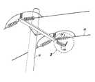
- FIG. 1shows a perspective view of a line arrester according to a first illustrative embodiment of the invention in association with an insulator on a utility pole;
- FIG. 2shows an enlarged perspective view of the FIG. 1 line arrester and insulator
- FIG. 3shows an exploded perspective view of the FIG. 1 line arrester
- FIG. 4shows a simplified schematic diagram of at least some of the elements within a separating device in the FIG. 1 line arrester
- FIG. 5shows a perspective view of the FIG. 1 line arrester after an SVU failure
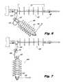
- FIG. 6shows a perspective view of a line arrester according to a second illustrative embodiment of the invention in association with an insulator
- FIG. 7shows a perspective view of the FIG. 6 line arrester after an SVU failure
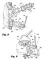
- FIG. 8shows a perspective view of a line arrester according to a third illustrative embodiment of the invention in association with an insulator on a utility pole;
- FIG. 9shows a perspective view of a line arrester according to a fourth illustrative embodiment of the invention in association with an insulator on a utility pole.
- FIGS. 1-3show several views of a line arrester 100 in accordance with an illustrative embodiment of the invention.
- the line arrester 100is presented in association with an insulator 105 tasked with supporting a power line 110 on a utility pole 115 .
- FIG. 1shows a perspective view of the line arrester 100 and the insulator 105 as they might be configured when installed on the utility pole 115 .
- FIG. 2shows an enlarged perspective view of the line arrester 100 and the insulator 105 .
- FIG. 3shows an exploded perspective view of at least some of the elements of the line arrester 100 itself.
- the illustrative line arrester 100comprises an electrode 120 , a separating device 125 , a strap 130 , an SVU 135 , and a bracket 140 .
- the insulator 105is what is commonly called a “dead end insulator,” although this choice for the type of insulator is largely arbitrary.
- the insulator 105comprises an insulator body 145 terminated at both ends by a respective conductive end fitting. As displayed in FIGS. 1 and 2 , the rightmost end fitting forms a line terminal 150 , while the leftmost end fitting forms an earth terminal 155 .
- the line terminal 150is preferably attached to and electrically tied to the power line 110 .
- the earth terminal 155in contrast, is preferably tied to an earth (ground) potential.
- one end of the electrode 120is coupled to the separating device 125 , while the opposite end terminates in the air.
- the air-terminated end of the electrode 120is precisely spaced apart from the line terminal 150 , defining an external gap 160 therebetween.
- the external gap 160is characterized by a distance D 0 .
- the separating device 125is coupled to the SVU 135 .
- the SVU 135is coupled to the bracket 140 , which, in this particular embodiment, ties that end of the line arrester 100 to the earth terminal 155 on the insulator 105 .
- the external gap 160 , the electrode 120 , the separating device 125 , the SVU 135 , and the bracket 140are thereby arranged in electrical series with each other and in electrical parallel with the insulator 105 .
- the strap 130spans between two ends of the separating device 125 .
- the SVU 135preferably comprises one or more non-linear resistors (i.e., varistors) that exhibit high resistances at normal applied voltages and much lower resistances at higher applied voltages such as those produced by lightning strikes.
- the non-linear resistors of the SVU 135may, for example, comprise one or more metal oxide elements such as, but not limited to, disks formed at least in part by zinc oxide.
- Commercial sources of suitable SVUsmay include, for example, Hubbell Power Systems (Centralia, Mo., USA), ABB (Norwalk, Conn., USA), Siemens AG (Er GmbH, Germany), and Cooper Power Systems (Dublin, Ireland).
- the SVU 135is preferably housed in a polymer housing to provide both weatherproofing and strength against electrically-induced explosions.
- the separating device 125preferably provides a low resistance pathway for electrical current until it is exposed to a voltage and associated current flow sufficient to cause the SVU 135 to fail.
- the separating device 125may, for example, take the form of a conventional ground lead disconnector (also sometimes called an “isolator”). Such ground lead disconnectors are commercially available from, as just two examples, DHGate.com (Beijing, China) and Zhejiang Smico Electric Power Equipment Co., Ltd. (Zhejiang, China).
- FIG. 4shows a simplified schematic diagram of at least some of the elements within the separating device 125 .
- the separating device 125comprises a bypass element 400 , a heating element 405 , and a separation element 410 .
- electrical currentis conducted primarily through the bypass element 400 and the heating element 405 is only nominally heated.
- a lightning strike or other power surgeoccurs that is sufficient to cause the SVU 135 to fail, excessive fault current causes the heating element 405 to heat to a point where it activates the separation element 410 .
- the separation element 410is preferably a small explosive device which is heat activated. The exploding separation device 410 acts to split the separating device 125 into two portions. In the present case, a first portion 165 remains attached to the SVU 135 , while a second portion 170 remains attached to the electrode 120 .
- the strap 130is operative to span between the two portions 165 , 170 of the separating device 125 after the separating device 125 is activated.
- the strap 130preferably comprises a flexible material of sufficient strength to support the weight of at least the second portion 170 and the electrode 120 .
- the strap 130will also preferably be of a high enough electrical resistance to not act as a significant current pathway in electrical parallel with the separating device 125 , while also being sufficiently heat resistant to withstand any heat generated by the separating device 125 and any localized electrical arcing.
- Suitable materials for the strap 130may include, as just two examples, Nomex® or Kevlar®, both available from DuPont (Wilmington, Del., USA).
- FIG. 3shows one manner in which the strap 130 can be secured to the separating device 125 , although this particular configuration is merely illustrative and ultimately any suitable means of attachment would still fall within the scope of the invention.
- the strap 130comprises two holes 180 positioned proximate to the strap's respective ends.
- a first threaded pin 185 emanating from the first portion 165 of the separating device 125passes through one of these holes 180 and is screwed into the SVU 135 .
- a second threaded pin 190 emanating from the second portion 170 of the separating device 125is passed through the other hole 180 in the strap 130 and, after passing through a first washer 195 , a hole in the electrode 120 , and a second washer 200 , is ultimately secured by a nut 205 .
- the second threaded pin 190 and associated securing hardware 195 , 200 , 205thereby act to capture both the strap 130 and the electrode 120 .
- the electrode 120 and the bracket 140preferably comprise a conductive material such as brass, iron, aluminum, stainless steel, or the like.
- the line arrester 100may act to protect the insulator 105 from flashover between the line terminal 150 and the earth terminal 155 . If a voltage surge is of sufficient amplitude to spark over the insulator 105 across strike distance D 0 , the surge is instead diverted across external gap 160 into the SVU 135 , which almost instantly becomes a low resistance pathway. In this manner, the surge is directed into the bracket 140 and ultimately to the earth terminal 155 (i.e., ground potential), thereby bypassing the insulator 105 altogether. Assuming that the SVU 135 does not fail, the SVU 135 again returns to its high resistance state and cuts off the current flow after the surge charge has been reduced in amplitude, effectively ending the diversion event. The line arrester 100 remains intact and ready to divert additional surges as necessary.
- the separating device 125preferably activates and separates into the first portion 165 and the second portion 170 , as detailed above.
- the first portion 165 of the separating device 125remains coupled to the SVU 135
- the second portion 170remains coupled to the electrode 120 .
- Gravity or, alternatively, a non-conductive spring built into the separating device 125then causes the second portion 170 and the electrode 120 to fall away from the remainder of the line arrester 100 until their fall is arrested by the strap 130 .
- the second portion 170 of the separating device 125 and the electrode 120end up suspended from the first portion 165 of the separating device 125 by the strap 130 .
- Such a “failed” conditionis shown in the perspective view in FIG. 5 .
- the illustrative line arrester 100provides several advantages when compared to a conventional EGLA.
- the distance between the first portion 165 of the separating device 125 and the line terminal 150becomes D 2 .
- the strike distance of the insulator 105is again D 1 .
- the capacity of the insulator 105 to experience flashoveris reset to the capacity of the insulator 105 to experience flashover without the line arrester 100 .
- the BIL of the systemis reestablished to about what it would be without the line arrester 100 .
- a conventional EGLAarranged in a manner similar to the line arrester 100 , but without a separating device like the separating device 125 , would exhibit very different electrical characteristics. More particularly, despite an SVU failure, the electrode of the conventional EGLA would remain configured as it had been before the failure occurred. The external gap of the conventional EGLA would thereby be maintained even though the SVU had been overloaded and was in a permanent low resistance state. The external gap distance D 0 of the conventional EGLA would then be the critical strike distance that governs the insulator 105 . As a result, in contrast to the line arrester 100 , system BIL with a conventional but failed EGLA would be substantially diminished because D 0 is shorter than D 1 .
- the illustrative line arrester 100is also advantageous because the portions of the line arrester 100 suspended by the strap 130 after a failure, namely, the second portion 170 of the separating device 125 and the electrode 120 , provide an excellent visual indicator that the line arrester 100 has been overloaded, which is not present in conventional EGLAs. Such a visual indicator, which may be seen at substantial distances, makes the discovery and repair of failed line arresters such as the line arrester 100 substantially easier.
- the strap 130assures that no parts are allowed to depart the line arrester 100 and fall from the utility pole 115 when a failure occurs. Thus, people and property underneath the utility pole 115 are protected from falling objects.
- FIG. 6goes on to show a perspective view of a slightly modified version of the line arrester 100 , namely, a line arrester 600 in accordance with a second illustrative embodiment of the invention.
- the line arrester 600comprises an external gap 605 , an electrode 610 , a separating device 615 , a strap 620 , a series varistor unit (SVU) 625 , and a bracket 630 .
- the external gap 605 , the electrode 610 , the separating device 615 , the SVU 625 , and the bracket 630are arranged in electrical series with each other while being in electrical parallel with an insulator 635 that they act to protect.
- the separating device 615 and the strap 620are coupled between the SVU 625 and the bracket 630 rather than being coupled between the SVU 625 and the electrode 610 in the manner of the line arrester 100 . Accordingly, upon failure of the SVU 625 and the activation of the separating device 615 , the SVU 625 and the electrode 610 end up suspended below the remainder of the line arrester 600 , as shown in the perspective view in FIG. 7 . For this reason, the strap 620 may need to be somewhat stronger than the strap 130 .
- the critical strike distance for the insulator 635again reverts to about D 1 , the value it would have been if the line arrester 600 had never been installed.
- the suspended SVU 625 and the suspended electrode 610act as excellent visual indicators of the failure, and, as before, no parts are allowed to drop from the utility pole 115 as a result of that failure.
- insulators 105 and 635While the previous two illustrative embodiments were described in terms of protecting a dead end type of insulator (i.e., insulators 105 and 635 ), aspects of the invention may be utilized with a wide assortment of different types of insulators that are commonly mounted on utility poles. These include, but art not limited to post-type, suspension-type, pin-type, and crossarm-type insulators, and the like. Such insulators and other aspects of power transmission and distribution are described in, for example, A. R. Hileman, Insulation Coordination for Power Systems , Marcel Dekker, Inc., New York, 1999, which is hereby incorporated by reference herein.
- FIG. 8shows a perspective view of a line arrester 800 in accordance with a third illustrative embodiment of the invention.
- the line arrester 800is configured to protect a horizontal post insulator 805 with a line terminal 810 and an earth terminal 815 .
- the line arrester 800comprises an external gap 820 , an electrode 825 , a separating device 830 , a strap 835 , an SVU 840 , and a first bracket 845 .
- the first bracket 845is in electrical communication with the earth terminal 810 of the horizontal post insulator 805 through a second bracket 850 , which is directly attached to a utility pole 855 and is preferably tied to earth potential. Configured in this manner, the line arrester 800 functions in substantially the same manner as the line arrester 100 described in detail above.
- FIG. 9shows a perspective view of a line arrester 900 in accordance with a fourth illustrative embodiment of the invention configured to protect a pin insulator 905 .
- the illustrative line arrester 900comprises an electrode 910 , a separating device 915 , a strap 920 , an SVU 925 , and a bracket 930 .
- the bracket 930is coupled to a pin 935 that passes through a crossbeam of a utility pole 940 and acts to form an earth terminal for the pin insulator 905 .
- a power line 945is supported by the pin insulator 905 and combines with the electrode 910 to define an external gap 950 .
- the line arrester 900functions in substantially the same manner as the line arrester 100 .
- any element in a claim that does not explicitly state “means for” performing a specified function or “step for” performing a specified functionis not to be interpreted as a “means for” or “step for” clause as specified in 35 U.S.C. ⁇ 112, Paragraph 6.
- the use of “step of” in the claims hereinis not intended to invoke the provisions of 35 U.S.C. ⁇ 112, Paragraph 6.
Landscapes
- Thermistors And Varistors (AREA)
Abstract
Description
The present invention relates generally to high voltage electrical power station, transmission, and distribution systems, and, more particularly, to line arresters for use in protecting such systems.
Externally Gapped Line Arresters (EGLAs) are a type of line arrester used to mitigate the effects of lightning strikes and electrical surges on electrical power line equipment. An EGLA is typically installed in electrical parallel with an insulator that acts to support a power line. With such an EGLA in place, lightning strikes or other types of voltage surges that might cause the insulator to experience flashover are instead diverted to the ground. Damaged equipment and service interruptions are thereby avoided.
While not utilized extensively in the United States, EGLAs have been in production and use in Japan and other foreign countries for several years. A typical EGLA comprises an external gap in series with a series varistor unit (SVU). The SVU, in turn, comprises non-linear metal oxide resistors (MORs) encapsulated in a polymer housing. Because of the non-linear behavior of MORs, the SVU exhibits high resistance at normal operating voltages, but rapidly becomes a low resistance pathway at higher applied voltages such as those produced by lightning strikes. The external gap, because it is arranged in series with the SVU, must spark over before the SVU can begin to conduct electricity.
Unfortunately, it is possible for an SVU in a conventional EGLA to experience a voltage condition during a lightning strike or other surge event sufficient to cause that SVU to fail and not revert back to its original high resistance state when the strike or surge is over. With such a failed SVU, system basic impulse level (BIL) is compromised and the EGLA no longer provides optimal protection for the equipment that it is intended to protect. Nevertheless, because SVUs are normally constructed with polymer housings for purposes of strength and explosion control, there is frequently no obvious outer indication that an SVU has failed. This makes the tracking down and repair of failed EGLAs particularly difficult for the utilities charged with maintaining that equipment.
Embodiments of the present invention provide EGLA designs that may be used to prevent insulators on utility poles from experiencing flashover as a result of lightning strikes or other electrical surge events.
In accordance with aspects of the invention, an arrester for preventing an insulator supporting a power line from experiencing an electrical flashover comprises an electrode, a varistor, and a separating device. The electrode is spaced apart from the power line or a conductor that is electrically tied to the power line so as to define an external gap therebetween. The separating device, in turn, comprises two portions operative to separate from one another when the varistor experiences an electrical condition sufficient to cause the varistor to fail. The electrode, the external gap, the separating device, and the varistor are arranged in electrical series with one another and in electrical parallel with the insulator.
Advantageously, the above-described embodiments provide several benefits over conventional EGLAs. Embodiments of the invention, for example: 1) provide a visual indication after an SVU failure; 2) allow the BIL of the insulator to be restored after an SVU failure to a value that it would have without a line arrester rather than being diminished; 3) do not allow parts to fall to the ground when an SVU failure occurs; and 4) may be configured for use with many different types of insulators.
These and other features, aspects, and advantages of the present invention will become better understood with regard to the following description, appended claims, and accompanying drawings where:
The present invention will be described with reference to illustrative embodiments. For this reason, numerous modifications can be made to these embodiments and the results will still come within the scope of the invention. No limitations with respect to the specific embodiments described herein are intended or should be inferred.
Theillustrative line arrester 100 comprises anelectrode 120, aseparating device 125, astrap 130, anSVU 135, and abracket 140. In the present embodiment, theinsulator 105 is what is commonly called a “dead end insulator,” although this choice for the type of insulator is largely arbitrary. Theinsulator 105 comprises an insulator body145 terminated at both ends by a respective conductive end fitting. As displayed inFIGS. 1 and 2 , the rightmost end fitting forms aline terminal 150, while the leftmost end fitting forms anearth terminal 155. When in use, theline terminal 150 is preferably attached to and electrically tied to thepower line 110. Theearth terminal 155, in contrast, is preferably tied to an earth (ground) potential.
Again referring toFIGS. 1-3 , one end of theelectrode 120 is coupled to the separatingdevice 125, while the opposite end terminates in the air. The air-terminated end of theelectrode 120 is precisely spaced apart from theline terminal 150, defining anexternal gap 160 therebetween. Theexternal gap 160 is characterized by a distance D0. Opposite theelectrode 120, theseparating device 125 is coupled to theSVU 135. TheSVU 135, in turn, is coupled to thebracket 140, which, in this particular embodiment, ties that end of the line arrester100 to theearth terminal 155 on theinsulator 105. Theexternal gap 160, theelectrode 120, theseparating device 125, theSVU 135, and thebracket 140 are thereby arranged in electrical series with each other and in electrical parallel with theinsulator 105. Finally, thestrap 130 spans between two ends of theseparating device 125.
TheSVU 135 preferably comprises one or more non-linear resistors (i.e., varistors) that exhibit high resistances at normal applied voltages and much lower resistances at higher applied voltages such as those produced by lightning strikes. The non-linear resistors of theSVU 135, may, for example, comprise one or more metal oxide elements such as, but not limited to, disks formed at least in part by zinc oxide. Commercial sources of suitable SVUs may include, for example, Hubbell Power Systems (Centralia, Mo., USA), ABB (Norwalk, Conn., USA), Siemens AG (Erlangen, Germany), and Cooper Power Systems (Dublin, Ireland). As described earlier, although generally robust, such SVUs may fail (i.e., enter a state wherein they are permanently in a lower resistance state) when exposed to extreme electrical conditions. Accordingly, the SVU135 is preferably housed in a polymer housing to provide both weatherproofing and strength against electrically-induced explosions.
For electrical continuity between theelectrode 120 and theSVU 135, theseparating device 125 preferably provides a low resistance pathway for electrical current until it is exposed to a voltage and associated current flow sufficient to cause theSVU 135 to fail. Theseparating device 125 may, for example, take the form of a conventional ground lead disconnector (also sometimes called an “isolator”). Such ground lead disconnectors are commercially available from, as just two examples, DHGate.com (Beijing, China) and Zhejiang Smico Electric Power Equipment Co., Ltd. (Zhejiang, China).FIG. 4 shows a simplified schematic diagram of at least some of the elements within theseparating device 125. Theseparating device 125 comprises abypass element 400, aheating element 405, and aseparation element 410. During normal, steady state operations, electrical current is conducted primarily through thebypass element 400 and theheating element 405 is only nominally heated. When, in contrast, a lightning strike or other power surge occurs that is sufficient to cause theSVU 135 to fail, excessive fault current causes theheating element 405 to heat to a point where it activates theseparation element 410. Theseparation element 410 is preferably a small explosive device which is heat activated. The explodingseparation device 410 acts to split theseparating device 125 into two portions. In the present case, afirst portion 165 remains attached to theSVU 135, while asecond portion 170 remains attached to theelectrode 120.
As will be further described below, thestrap 130 is operative to span between the twoportions separating device 125 after theseparating device 125 is activated. Accordingly, thestrap 130 preferably comprises a flexible material of sufficient strength to support the weight of at least thesecond portion 170 and theelectrode 120. Thestrap 130 will also preferably be of a high enough electrical resistance to not act as a significant current pathway in electrical parallel with theseparating device 125, while also being sufficiently heat resistant to withstand any heat generated by theseparating device 125 and any localized electrical arcing. Suitable materials for thestrap 130 may include, as just two examples, Nomex® or Kevlar®, both available from DuPont (Wilmington, Del., USA).
Finally, theelectrode 120 and thebracket 140 preferably comprise a conductive material such as brass, iron, aluminum, stainless steel, or the like.
Once so configured, theline arrester 100 may act to protect theinsulator 105 from flashover between theline terminal 150 and theearth terminal 155. If a voltage surge is of sufficient amplitude to spark over theinsulator 105 across strike distance D0, the surge is instead diverted acrossexternal gap 160 into theSVU 135, which almost instantly becomes a low resistance pathway. In this manner, the surge is directed into thebracket 140 and ultimately to the earth terminal155 (i.e., ground potential), thereby bypassing theinsulator 105 altogether. Assuming that theSVU 135 does not fail, theSVU 135 again returns to its high resistance state and cuts off the current flow after the surge charge has been reduced in amplitude, effectively ending the diversion event. Theline arrester 100 remains intact and ready to divert additional surges as necessary.
If, instead, the electrical surge is sufficient to fail theSVU 135, a very different sequence of events occurs. In response to the overloading of theSVU 135, theseparating device 125 preferably activates and separates into thefirst portion 165 and thesecond portion 170, as detailed above. Thefirst portion 165 of theseparating device 125 remains coupled to theSVU 135, while thesecond portion 170 remains coupled to theelectrode 120. Gravity or, alternatively, a non-conductive spring built into theseparating device 125, then causes thesecond portion 170 and theelectrode 120 to fall away from the remainder of theline arrester 100 until their fall is arrested by thestrap 130. At the end of this sequence of events, thesecond portion 170 of theseparating device 125 and theelectrode 120 end up suspended from thefirst portion 165 of theseparating device 125 by thestrap 130. Such a “failed” condition is shown in the perspective view inFIG. 5 .
Notably, theillustrative line arrester 100 provides several advantages when compared to a conventional EGLA. With theelectrode 120 suspended below the remainder of theline arrester 100 after failure of theSVU 135, as shown inFIG. 5 , the distance between thefirst portion 165 of theseparating device 125 and theline terminal 150 becomes D2. Advantageously, if the distance D2 is similar to or greater than the distance D1, as is preferable, the strike distance of theinsulator 105 is again D1. In other words, the capacity of theinsulator 105 to experience flashover is reset to the capacity of theinsulator 105 to experience flashover without theline arrester 100. Accordingly, the BIL of the system is reestablished to about what it would be without theline arrester 100. In contrast, a conventional EGLA, arranged in a manner similar to theline arrester 100, but without a separating device like theseparating device 125, would exhibit very different electrical characteristics. More particularly, despite an SVU failure, the electrode of the conventional EGLA would remain configured as it had been before the failure occurred. The external gap of the conventional EGLA would thereby be maintained even though the SVU had been overloaded and was in a permanent low resistance state. The external gap distance D0 of the conventional EGLA would then be the critical strike distance that governs theinsulator 105. As a result, in contrast to theline arrester 100, system BIL with a conventional but failed EGLA would be substantially diminished because D0 is shorter than D1.
What is more, theillustrative line arrester 100 is also advantageous because the portions of theline arrester 100 suspended by thestrap 130 after a failure, namely, thesecond portion 170 of theseparating device 125 and theelectrode 120, provide an excellent visual indicator that theline arrester 100 has been overloaded, which is not present in conventional EGLAs. Such a visual indicator, which may be seen at substantial distances, makes the discovery and repair of failed line arresters such as theline arrester 100 substantially easier. At the same time, thestrap 130 assures that no parts are allowed to depart theline arrester 100 and fall from theutility pole 115 when a failure occurs. Thus, people and property underneath theutility pole 115 are protected from falling objects.
Nevertheless, in theline arrester 600, theseparating device 615 and thestrap 620 are coupled between theSVU 625 and thebracket 630 rather than being coupled between theSVU 625 and theelectrode 610 in the manner of theline arrester 100. Accordingly, upon failure of theSVU 625 and the activation of theseparating device 615, theSVU 625 and theelectrode 610 end up suspended below the remainder of theline arrester 600, as shown in the perspective view inFIG. 7 . For this reason, thestrap 620 may need to be somewhat stronger than thestrap 130. That said, with theSVU 625 and theelectrode 610 suspended in this manner, the critical strike distance for theinsulator 635 again reverts to about D1, the value it would have been if theline arrester 600 had never been installed. At the same time, the suspendedSVU 625 and the suspendedelectrode 610 act as excellent visual indicators of the failure, and, as before, no parts are allowed to drop from theutility pole 115 as a result of that failure.
While the previous two illustrative embodiments were described in terms of protecting a dead end type of insulator (i.e.,insulators 105 and635), aspects of the invention may be utilized with a wide assortment of different types of insulators that are commonly mounted on utility poles. These include, but art not limited to post-type, suspension-type, pin-type, and crossarm-type insulators, and the like. Such insulators and other aspects of power transmission and distribution are described in, for example, A. R. Hileman,Insulation Coordination for Power Systems, Marcel Dekker, Inc., New York, 1999, which is hereby incorporated by reference herein.
As even another example,FIG. 9 shows a perspective view of aline arrester 900 in accordance with a fourth illustrative embodiment of the invention configured to protect apin insulator 905. Here, theillustrative line arrester 900 comprises anelectrode 910, aseparating device 915, astrap 920, anSVU 925, and abracket 930. Thebracket 930, in turn, is coupled to apin 935 that passes through a crossbeam of autility pole 940 and acts to form an earth terminal for thepin insulator 905. Apower line 945 is supported by thepin insulator 905 and combines with theelectrode 910 to define anexternal gap 950. Again, in such a configuration, theline arrester 900 functions in substantially the same manner as theline arrester 100.
In closing, it should again be emphasized that the above-described embodiments of the invention are intended to be illustrative only. Other embodiments can use different types and arrangements of elements for implementing the described functionality, and these numerous alternative embodiments within the scope of the appended claims will be apparent to one skilled in the art. In addition, it is reiterated that all the features disclosed herein may be replaced by alternative features serving the same, equivalent, or similar purposes, unless expressly stated otherwise. Thus, unless expressly stated otherwise, each feature disclosed is one example only of a generic series of equivalent or similar features.
Moreover, any element in a claim that does not explicitly state “means for” performing a specified function or “step for” performing a specified function is not to be interpreted as a “means for” or “step for” clause as specified in 35 U.S.C. §112, Paragraph 6. In particular, the use of “step of” in the claims herein is not intended to invoke the provisions of 35 U.S.C. §112, Paragraph 6.
Claims (19)
1. An arrester for preventing an insulator supporting a power line from experiencing an electrical flashover, the arrester comprising:
an electrode, the electrode spaced apart from: (a) the power line, or (b) a conductor that is distinct from the power line, so as to define an external gap therebetween;
a varistor;
a separating device, the separating device comprising two portions operative to separate from one another when the varistor experiences an electrical condition sufficient to cause the varistor to fail; and
a strap, the strap being continuous and defining two ends, each of the two ends coupled to a respective one of the two portions of the separating device;
wherein the electrode, the external gap, the separating device, and the varistor are arranged in electrical series with one another and in electrical parallel with the insulator;
wherein the strap is operative to span between the two portions of the separating device after the separating device separates into the two portions.
2. The arrester ofclaim 1 , wherein the strap is substantially flexible.
3. The arrester ofclaim 1 , wherein the strap is operative to allow one of the two portions of the separating device to be suspended from the other after the separating device separates into the two portions.
4. The arrester ofclaim 1 , wherein the strap is operative to allow at least the electrode to be suspended from one of the two portions of the separating device after the separating device separates into the two portions.
5. The arrester ofclaim 1 , wherein the strap is operative to allow at least the varistor to be suspended from one of the two portions of the separating device after the separating device separates into the two portions.
6. The arrester ofclaim 1 , wherein the arrester is arranged such that the electrode is coupled to the separating device, and the separating device is coupled to the varistor.
7. The arrester ofclaim 1 , wherein the arrester is arranged such that the electrode is coupled to the varistor, and the varistor is coupled to the separating device.
8. The arrester ofclaim 1 , wherein the insulator comprises a terminal that is tied to an earth potential.
9. The arrester ofclaim 1 , wherein the arrester is adapted for use on a utility pole.
10. The arrester ofclaim 1 , wherein the separating device comprises an explosive device.
11. The arrester ofclaim 9 , wherein the explosive device is heat activated.
12. The arrester ofclaim 1 , wherein the varistor comprises a series varistor unit.
13. The arrester ofclaim 1 , wherein the varistor is characterized by a higher resistance at a lower applied voltage, and a lower resistance at a higher applied voltage.
14. The arrester ofclaim 1 , wherein a capacity of the insulator to experience an electrical flashover after the separating device separates into the two portions is substantially equal to a capacity of the insulator to experience an electrical flashover without the arrester.
15. The arrester ofclaim 1 , wherein the varistor comprises one or more non-linear metal oxide resistors.
16. The arrester ofclaim 1 , wherein the insulator comprises at least one of a suspension-type, a post-type, a pin-type, and a crossarm-type insulator.
17. A method for preventing an insulator supporting a power line from experiencing an electrical flashover, the method comprising the steps of:
positioning an electrode apart from: (a) the power line, or (b) a conductor that is distinct from the power line, so as to define an external gap therebetween;
receiving a varistor;
receiving a separating device, the separating device comprising two portions operative to separate from one another when the varistor experiences an electrical condition sufficient to cause the varistor to fail;
receiving a strap, the strap being continuous and defining two ends;
arranging the strap such that each of the two ends is coupled to a respective one of the two portions of the separating device; and
arranging the electrode, the external gap, the separating device, and the varistor in electrical series with one another and in electrical parallel with the insulator;
wherein the strap is operative to span between the two portions of the separating device after the separating device separates into the two portions.
18. An apparatus comprising:
an insulator, the insulator supporting a power line;
an electrode, the electrode spaced apart from: (a) the power line, or (b) a conductor that is distinct from the power line, so as to define an external gap therebetween;
a varistor;
a separating device, the separating device comprising two portions operative to separate from one another when the varistor experiences an electrical condition sufficient to cause the varistor to fail; and
a strap, the strap being continuous and defining two ends, each of the two ends coupled to a respective one of the two portions of the separating device;
wherein the electrode, the external gap, the separating device, and the varistor are arranged in electrical series with one another and in electrical parallel with the insulator;
wherein the strap is operative to span between the two portions of the separating device after the separating device separates into the two portions.
19. The line arrester ofclaim 1 , wherein the conductor is electrically tied to the power line.
Priority Applications (1)
| Application Number | Priority Date | Filing Date | Title |
|---|---|---|---|
| US13/253,362US8711538B2 (en) | 2010-10-06 | 2011-10-05 | Externally gapped line arrester |
Applications Claiming Priority (2)
| Application Number | Priority Date | Filing Date | Title |
|---|---|---|---|
| US39021810P | 2010-10-06 | 2010-10-06 | |
| US13/253,362US8711538B2 (en) | 2010-10-06 | 2011-10-05 | Externally gapped line arrester |
Publications (2)
| Publication Number | Publication Date |
|---|---|
| US20120087055A1 US20120087055A1 (en) | 2012-04-12 |
| US8711538B2true US8711538B2 (en) | 2014-04-29 |
Family
ID=45924961
Family Applications (1)
| Application Number | Title | Priority Date | Filing Date |
|---|---|---|---|
| US13/253,362Active2032-09-26US8711538B2 (en) | 2010-10-06 | 2011-10-05 | Externally gapped line arrester |
Country Status (1)
| Country | Link |
|---|---|
| US (1) | US8711538B2 (en) |
Cited By (119)
| Publication number | Priority date | Publication date | Assignee | Title |
|---|---|---|---|---|
| US9674711B2 (en) | 2013-11-06 | 2017-06-06 | At&T Intellectual Property I, L.P. | Surface-wave communications and methods thereof |
| US9685992B2 (en) | 2014-10-03 | 2017-06-20 | At&T Intellectual Property I, L.P. | Circuit panel network and methods thereof |
| US9705561B2 (en) | 2015-04-24 | 2017-07-11 | At&T Intellectual Property I, L.P. | Directional coupling device and methods for use therewith |
| US9705610B2 (en) | 2014-10-21 | 2017-07-11 | At&T Intellectual Property I, L.P. | Transmission device with impairment compensation and methods for use therewith |
| US9729197B2 (en) | 2015-10-01 | 2017-08-08 | At&T Intellectual Property I, L.P. | Method and apparatus for communicating network management traffic over a network |
| US9735833B2 (en) | 2015-07-31 | 2017-08-15 | At&T Intellectual Property I, L.P. | Method and apparatus for communications management in a neighborhood network |
| US9742521B2 (en) | 2014-11-20 | 2017-08-22 | At&T Intellectual Property I, L.P. | Transmission device with mode division multiplexing and methods for use therewith |
| US9742462B2 (en) | 2014-12-04 | 2017-08-22 | At&T Intellectual Property I, L.P. | Transmission medium and communication interfaces and methods for use therewith |
| US9749053B2 (en) | 2015-07-23 | 2017-08-29 | At&T Intellectual Property I, L.P. | Node device, repeater and methods for use therewith |
| US9748626B2 (en) | 2015-05-14 | 2017-08-29 | At&T Intellectual Property I, L.P. | Plurality of cables having different cross-sectional shapes which are bundled together to form a transmission medium |
| US9749013B2 (en) | 2015-03-17 | 2017-08-29 | At&T Intellectual Property I, L.P. | Method and apparatus for reducing attenuation of electromagnetic waves guided by a transmission medium |
| US9769128B2 (en) | 2015-09-28 | 2017-09-19 | At&T Intellectual Property I, L.P. | Method and apparatus for encryption of communications over a network |
| US9769020B2 (en) | 2014-10-21 | 2017-09-19 | At&T Intellectual Property I, L.P. | Method and apparatus for responding to events affecting communications in a communication network |
| US9768833B2 (en) | 2014-09-15 | 2017-09-19 | At&T Intellectual Property I, L.P. | Method and apparatus for sensing a condition in a transmission medium of electromagnetic waves |
| US9780834B2 (en) | 2014-10-21 | 2017-10-03 | At&T Intellectual Property I, L.P. | Method and apparatus for transmitting electromagnetic waves |
| US20170288382A1 (en)* | 2016-04-05 | 2017-10-05 | General Electric Technology Gmbh | Supporting structure for contacts of high-voltage disconnectors |
| US9787412B2 (en) | 2015-06-25 | 2017-10-10 | At&T Intellectual Property I, L.P. | Methods and apparatus for inducing a fundamental wave mode on a transmission medium |
| US9793954B2 (en) | 2015-04-28 | 2017-10-17 | At&T Intellectual Property I, L.P. | Magnetic coupling device and methods for use therewith |
| US9793955B2 (en) | 2015-04-24 | 2017-10-17 | At&T Intellectual Property I, Lp | Passive electrical coupling device and methods for use therewith |
| US9800327B2 (en) | 2014-11-20 | 2017-10-24 | At&T Intellectual Property I, L.P. | Apparatus for controlling operations of a communication device and methods thereof |
| US9820146B2 (en) | 2015-06-12 | 2017-11-14 | At&T Intellectual Property I, L.P. | Method and apparatus for authentication and identity management of communicating devices |
| US9838896B1 (en) | 2016-12-09 | 2017-12-05 | At&T Intellectual Property I, L.P. | Method and apparatus for assessing network coverage |
| US9838078B2 (en) | 2015-07-31 | 2017-12-05 | At&T Intellectual Property I, L.P. | Method and apparatus for exchanging communication signals |
| US9847850B2 (en) | 2014-10-14 | 2017-12-19 | At&T Intellectual Property I, L.P. | Method and apparatus for adjusting a mode of communication in a communication network |
| US9847566B2 (en) | 2015-07-14 | 2017-12-19 | At&T Intellectual Property I, L.P. | Method and apparatus for adjusting a field of a signal to mitigate interference |
| US9853342B2 (en) | 2015-07-14 | 2017-12-26 | At&T Intellectual Property I, L.P. | Dielectric transmission medium connector and methods for use therewith |
| US9860075B1 (en) | 2016-08-26 | 2018-01-02 | At&T Intellectual Property I, L.P. | Method and communication node for broadband distribution |
| US9866276B2 (en) | 2014-10-10 | 2018-01-09 | At&T Intellectual Property I, L.P. | Method and apparatus for arranging communication sessions in a communication system |
| US9866309B2 (en) | 2015-06-03 | 2018-01-09 | At&T Intellectual Property I, Lp | Host node device and methods for use therewith |
| US9865911B2 (en) | 2015-06-25 | 2018-01-09 | At&T Intellectual Property I, L.P. | Waveguide system for slot radiating first electromagnetic waves that are combined into a non-fundamental wave mode second electromagnetic wave on a transmission medium |
| US9871282B2 (en) | 2015-05-14 | 2018-01-16 | At&T Intellectual Property I, L.P. | At least one transmission medium having a dielectric surface that is covered at least in part by a second dielectric |
| US9871558B2 (en) | 2014-10-21 | 2018-01-16 | At&T Intellectual Property I, L.P. | Guided-wave transmission device and methods for use therewith |
| US9871283B2 (en) | 2015-07-23 | 2018-01-16 | At&T Intellectual Property I, Lp | Transmission medium having a dielectric core comprised of plural members connected by a ball and socket configuration |
| US9876571B2 (en) | 2015-02-20 | 2018-01-23 | At&T Intellectual Property I, Lp | Guided-wave transmission device with non-fundamental mode propagation and methods for use therewith |
| US9876264B2 (en) | 2015-10-02 | 2018-01-23 | At&T Intellectual Property I, Lp | Communication system, guided wave switch and methods for use therewith |
| US9876605B1 (en) | 2016-10-21 | 2018-01-23 | At&T Intellectual Property I, L.P. | Launcher and coupling system to support desired guided wave mode |
| US9882257B2 (en) | 2015-07-14 | 2018-01-30 | At&T Intellectual Property I, L.P. | Method and apparatus for launching a wave mode that mitigates interference |
| US9887447B2 (en) | 2015-05-14 | 2018-02-06 | At&T Intellectual Property I, L.P. | Transmission medium having multiple cores and methods for use therewith |
| US9893795B1 (en) | 2016-12-07 | 2018-02-13 | At&T Intellectual Property I, Lp | Method and repeater for broadband distribution |
| US9906269B2 (en) | 2014-09-17 | 2018-02-27 | At&T Intellectual Property I, L.P. | Monitoring and mitigating conditions in a communication network |
| US9904535B2 (en) | 2015-09-14 | 2018-02-27 | At&T Intellectual Property I, L.P. | Method and apparatus for distributing software |
| US9912027B2 (en) | 2015-07-23 | 2018-03-06 | At&T Intellectual Property I, L.P. | Method and apparatus for exchanging communication signals |
| US9911020B1 (en) | 2016-12-08 | 2018-03-06 | At&T Intellectual Property I, L.P. | Method and apparatus for tracking via a radio frequency identification device |
| US9912382B2 (en) | 2015-06-03 | 2018-03-06 | At&T Intellectual Property I, Lp | Network termination and methods for use therewith |
| US9912033B2 (en) | 2014-10-21 | 2018-03-06 | At&T Intellectual Property I, Lp | Guided wave coupler, coupling module and methods for use therewith |
| US9913139B2 (en) | 2015-06-09 | 2018-03-06 | At&T Intellectual Property I, L.P. | Signal fingerprinting for authentication of communicating devices |
| US9917341B2 (en) | 2015-05-27 | 2018-03-13 | At&T Intellectual Property I, L.P. | Apparatus and method for launching electromagnetic waves and for modifying radial dimensions of the propagating electromagnetic waves |
| US9927517B1 (en) | 2016-12-06 | 2018-03-27 | At&T Intellectual Property I, L.P. | Apparatus and methods for sensing rainfall |
| US9929755B2 (en) | 2015-07-14 | 2018-03-27 | At&T Intellectual Property I, L.P. | Method and apparatus for coupling an antenna to a device |
| US9948333B2 (en) | 2015-07-23 | 2018-04-17 | At&T Intellectual Property I, L.P. | Method and apparatus for wireless communications to mitigate interference |
| US9954286B2 (en) | 2014-10-21 | 2018-04-24 | At&T Intellectual Property I, L.P. | Guided-wave transmission device with non-fundamental mode propagation and methods for use therewith |
| US9954287B2 (en) | 2014-11-20 | 2018-04-24 | At&T Intellectual Property I, L.P. | Apparatus for converting wireless signals and electromagnetic waves and methods thereof |
| US9967173B2 (en) | 2015-07-31 | 2018-05-08 | At&T Intellectual Property I, L.P. | Method and apparatus for authentication and identity management of communicating devices |
| US9973416B2 (en) | 2014-10-02 | 2018-05-15 | At&T Intellectual Property I, L.P. | Method and apparatus that provides fault tolerance in a communication network |
| US9973940B1 (en) | 2017-02-27 | 2018-05-15 | At&T Intellectual Property I, L.P. | Apparatus and methods for dynamic impedance matching of a guided wave launcher |
| US9991580B2 (en) | 2016-10-21 | 2018-06-05 | At&T Intellectual Property I, L.P. | Launcher and coupling system for guided wave mode cancellation |
| US9999038B2 (en) | 2013-05-31 | 2018-06-12 | At&T Intellectual Property I, L.P. | Remote distributed antenna system |
| US9997819B2 (en) | 2015-06-09 | 2018-06-12 | At&T Intellectual Property I, L.P. | Transmission medium and method for facilitating propagation of electromagnetic waves via a core |
| US9998870B1 (en) | 2016-12-08 | 2018-06-12 | At&T Intellectual Property I, L.P. | Method and apparatus for proximity sensing |
| US10009067B2 (en) | 2014-12-04 | 2018-06-26 | At&T Intellectual Property I, L.P. | Method and apparatus for configuring a communication interface |
| US10020844B2 (en) | 2016-12-06 | 2018-07-10 | T&T Intellectual Property I, L.P. | Method and apparatus for broadcast communication via guided waves |
| US10027397B2 (en) | 2016-12-07 | 2018-07-17 | At&T Intellectual Property I, L.P. | Distributed antenna system and methods for use therewith |
| US10044409B2 (en) | 2015-07-14 | 2018-08-07 | At&T Intellectual Property I, L.P. | Transmission medium and methods for use therewith |
| US10051630B2 (en) | 2013-05-31 | 2018-08-14 | At&T Intellectual Property I, L.P. | Remote distributed antenna system |
| US10069185B2 (en) | 2015-06-25 | 2018-09-04 | At&T Intellectual Property I, L.P. | Methods and apparatus for inducing a non-fundamental wave mode on a transmission medium |
| US10069535B2 (en) | 2016-12-08 | 2018-09-04 | At&T Intellectual Property I, L.P. | Apparatus and methods for launching electromagnetic waves having a certain electric field structure |
| US10090594B2 (en) | 2016-11-23 | 2018-10-02 | At&T Intellectual Property I, L.P. | Antenna system having structural configurations for assembly |
| US10090606B2 (en) | 2015-07-15 | 2018-10-02 | At&T Intellectual Property I, L.P. | Antenna system with dielectric array and methods for use therewith |
| US10103422B2 (en) | 2016-12-08 | 2018-10-16 | At&T Intellectual Property I, L.P. | Method and apparatus for mounting network devices |
| US10135145B2 (en) | 2016-12-06 | 2018-11-20 | At&T Intellectual Property I, L.P. | Apparatus and methods for generating an electromagnetic wave along a transmission medium |
| US10139820B2 (en) | 2016-12-07 | 2018-11-27 | At&T Intellectual Property I, L.P. | Method and apparatus for deploying equipment of a communication system |
| US10148016B2 (en) | 2015-07-14 | 2018-12-04 | At&T Intellectual Property I, L.P. | Apparatus and methods for communicating utilizing an antenna array |
| US10168695B2 (en) | 2016-12-07 | 2019-01-01 | At&T Intellectual Property I, L.P. | Method and apparatus for controlling an unmanned aircraft |
| US10178445B2 (en) | 2016-11-23 | 2019-01-08 | At&T Intellectual Property I, L.P. | Methods, devices, and systems for load balancing between a plurality of waveguides |
| US10205655B2 (en) | 2015-07-14 | 2019-02-12 | At&T Intellectual Property I, L.P. | Apparatus and methods for communicating utilizing an antenna array and multiple communication paths |
| US10224634B2 (en) | 2016-11-03 | 2019-03-05 | At&T Intellectual Property I, L.P. | Methods and apparatus for adjusting an operational characteristic of an antenna |
| US10225025B2 (en) | 2016-11-03 | 2019-03-05 | At&T Intellectual Property I, L.P. | Method and apparatus for detecting a fault in a communication system |
| US10243784B2 (en) | 2014-11-20 | 2019-03-26 | At&T Intellectual Property I, L.P. | System for generating topology information and methods thereof |
| US10243270B2 (en) | 2016-12-07 | 2019-03-26 | At&T Intellectual Property I, L.P. | Beam adaptive multi-feed dielectric antenna system and methods for use therewith |
| US10264586B2 (en) | 2016-12-09 | 2019-04-16 | At&T Mobility Ii Llc | Cloud-based packet controller and methods for use therewith |
| US10291334B2 (en) | 2016-11-03 | 2019-05-14 | At&T Intellectual Property I, L.P. | System for detecting a fault in a communication system |
| US10298293B2 (en) | 2017-03-13 | 2019-05-21 | At&T Intellectual Property I, L.P. | Apparatus of communication utilizing wireless network devices |
| US10305190B2 (en) | 2016-12-01 | 2019-05-28 | At&T Intellectual Property I, L.P. | Reflecting dielectric antenna system and methods for use therewith |
| US10312567B2 (en) | 2016-10-26 | 2019-06-04 | At&T Intellectual Property I, L.P. | Launcher with planar strip antenna and methods for use therewith |
| US10326494B2 (en) | 2016-12-06 | 2019-06-18 | At&T Intellectual Property I, L.P. | Apparatus for measurement de-embedding and methods for use therewith |
| US10326689B2 (en) | 2016-12-08 | 2019-06-18 | At&T Intellectual Property I, L.P. | Method and system for providing alternative communication paths |
| US10340573B2 (en) | 2016-10-26 | 2019-07-02 | At&T Intellectual Property I, L.P. | Launcher with cylindrical coupling device and methods for use therewith |
| US10340603B2 (en) | 2016-11-23 | 2019-07-02 | At&T Intellectual Property I, L.P. | Antenna system having shielded structural configurations for assembly |
| US10340983B2 (en) | 2016-12-09 | 2019-07-02 | At&T Intellectual Property I, L.P. | Method and apparatus for surveying remote sites via guided wave communications |
| US10340601B2 (en) | 2016-11-23 | 2019-07-02 | At&T Intellectual Property I, L.P. | Multi-antenna system and methods for use therewith |
| US10355367B2 (en) | 2015-10-16 | 2019-07-16 | At&T Intellectual Property I, L.P. | Antenna structure for exchanging wireless signals |
| US10361489B2 (en) | 2016-12-01 | 2019-07-23 | At&T Intellectual Property I, L.P. | Dielectric dish antenna system and methods for use therewith |
| US10359749B2 (en) | 2016-12-07 | 2019-07-23 | At&T Intellectual Property I, L.P. | Method and apparatus for utilities management via guided wave communication |
| US10374316B2 (en) | 2016-10-21 | 2019-08-06 | At&T Intellectual Property I, L.P. | System and dielectric antenna with non-uniform dielectric |
| US10382976B2 (en) | 2016-12-06 | 2019-08-13 | At&T Intellectual Property I, L.P. | Method and apparatus for managing wireless communications based on communication paths and network device positions |
| US10389037B2 (en) | 2016-12-08 | 2019-08-20 | At&T Intellectual Property I, L.P. | Apparatus and methods for selecting sections of an antenna array and use therewith |
| US10389029B2 (en) | 2016-12-07 | 2019-08-20 | At&T Intellectual Property I, L.P. | Multi-feed dielectric antenna system with core selection and methods for use therewith |
| US10411356B2 (en) | 2016-12-08 | 2019-09-10 | At&T Intellectual Property I, L.P. | Apparatus and methods for selectively targeting communication devices with an antenna array |
| US10439675B2 (en) | 2016-12-06 | 2019-10-08 | At&T Intellectual Property I, L.P. | Method and apparatus for repeating guided wave communication signals |
| US10446936B2 (en) | 2016-12-07 | 2019-10-15 | At&T Intellectual Property I, L.P. | Multi-feed dielectric antenna system and methods for use therewith |
| US10498044B2 (en) | 2016-11-03 | 2019-12-03 | At&T Intellectual Property I, L.P. | Apparatus for configuring a surface of an antenna |
| US10530505B2 (en) | 2016-12-08 | 2020-01-07 | At&T Intellectual Property I, L.P. | Apparatus and methods for launching electromagnetic waves along a transmission medium |
| US10535928B2 (en) | 2016-11-23 | 2020-01-14 | At&T Intellectual Property I, L.P. | Antenna system and methods for use therewith |
| US10547348B2 (en) | 2016-12-07 | 2020-01-28 | At&T Intellectual Property I, L.P. | Method and apparatus for switching transmission mediums in a communication system |
| US10601494B2 (en) | 2016-12-08 | 2020-03-24 | At&T Intellectual Property I, L.P. | Dual-band communication device and method for use therewith |
| US10637149B2 (en) | 2016-12-06 | 2020-04-28 | At&T Intellectual Property I, L.P. | Injection molded dielectric antenna and methods for use therewith |
| US10650940B2 (en) | 2015-05-15 | 2020-05-12 | At&T Intellectual Property I, L.P. | Transmission medium having a conductive material and methods for use therewith |
| US10694379B2 (en) | 2016-12-06 | 2020-06-23 | At&T Intellectual Property I, L.P. | Waveguide system with device-based authentication and methods for use therewith |
| US10727599B2 (en) | 2016-12-06 | 2020-07-28 | At&T Intellectual Property I, L.P. | Launcher with slot antenna and methods for use therewith |
| US10755542B2 (en) | 2016-12-06 | 2020-08-25 | At&T Intellectual Property I, L.P. | Method and apparatus for surveillance via guided wave communication |
| US10777873B2 (en) | 2016-12-08 | 2020-09-15 | At&T Intellectual Property I, L.P. | Method and apparatus for mounting network devices |
| US10797781B2 (en) | 2015-06-03 | 2020-10-06 | At&T Intellectual Property I, L.P. | Client node device and methods for use therewith |
| US10811767B2 (en) | 2016-10-21 | 2020-10-20 | At&T Intellectual Property I, L.P. | System and dielectric antenna with convex dielectric radome |
| US10819035B2 (en) | 2016-12-06 | 2020-10-27 | At&T Intellectual Property I, L.P. | Launcher with helical antenna and methods for use therewith |
| US10916969B2 (en) | 2016-12-08 | 2021-02-09 | At&T Intellectual Property I, L.P. | Method and apparatus for providing power using an inductive coupling |
| US10938108B2 (en) | 2016-12-08 | 2021-03-02 | At&T Intellectual Property I, L.P. | Frequency selective multi-feed dielectric antenna system and methods for use therewith |
| US11322934B2 (en)* | 2016-09-13 | 2022-05-03 | Hitachi Energy Switzerland Ag | Protection of a surge arrester with a better protection against failure from thermal overload in case of a temporary overvoltage in an electrical grid line |
| US11322913B2 (en) | 2018-09-28 | 2022-05-03 | Hitachi Energy Switzerland Ag | Externally gapped line arrester |
| US11777298B2 (en) | 2020-07-13 | 2023-10-03 | Sean O'Reilly | Lightning diverter system and methods |
Families Citing this family (4)
| Publication number | Priority date | Publication date | Assignee | Title |
|---|---|---|---|---|
| EP2712038A1 (en) | 2012-09-25 | 2014-03-26 | Siemens Aktiengesellschaft | Guard electrode and line arrester with such a safety electrode |
| EP2854242B1 (en)* | 2013-09-25 | 2019-10-30 | Siemens Aktiengesellschaft | Assembly for fastening an overhead line to a mast |
| US9755420B2 (en)* | 2014-06-02 | 2017-09-05 | Cooper Technologies Company | Electrically insulated tethers for transmission line arresters |
| EP3073588A1 (en) | 2015-03-24 | 2016-09-28 | Siemens Aktiengesellschaft | Insulation kit for an overhead line |
Citations (7)
| Publication number | Priority date | Publication date | Assignee | Title |
|---|---|---|---|---|
| US3017539A (en)* | 1958-09-15 | 1962-01-16 | Porter Co Inc H K | Electrical disconnector for lightning arresters |
| US3474995A (en)* | 1967-06-23 | 1969-10-28 | Joseph C Amidon | Utility pole insulator bracket extension |
| US5172297A (en)* | 1990-05-24 | 1992-12-15 | Ngk Insulators, Ltd. | Lightning arrestor |
| US5237482A (en)* | 1991-07-10 | 1993-08-17 | Joslyn Corporation | High voltage surge arrester with failed surge arrester signaling device |
| US5400207A (en)* | 1993-11-18 | 1995-03-21 | Hubbell Incorporated | Isolator-arrester assembly |
| US5426555A (en)* | 1992-07-03 | 1995-06-20 | Asea Brown Boveri Ab | Surge arrester arrangement |
| US20110216463A1 (en)* | 2010-03-08 | 2011-09-08 | Kester Jeffrey J | Line protection systems |
- 2011
- 2011-10-05USUS13/253,362patent/US8711538B2/enactiveActive
Patent Citations (7)
| Publication number | Priority date | Publication date | Assignee | Title |
|---|---|---|---|---|
| US3017539A (en)* | 1958-09-15 | 1962-01-16 | Porter Co Inc H K | Electrical disconnector for lightning arresters |
| US3474995A (en)* | 1967-06-23 | 1969-10-28 | Joseph C Amidon | Utility pole insulator bracket extension |
| US5172297A (en)* | 1990-05-24 | 1992-12-15 | Ngk Insulators, Ltd. | Lightning arrestor |
| US5237482A (en)* | 1991-07-10 | 1993-08-17 | Joslyn Corporation | High voltage surge arrester with failed surge arrester signaling device |
| US5426555A (en)* | 1992-07-03 | 1995-06-20 | Asea Brown Boveri Ab | Surge arrester arrangement |
| US5400207A (en)* | 1993-11-18 | 1995-03-21 | Hubbell Incorporated | Isolator-arrester assembly |
| US20110216463A1 (en)* | 2010-03-08 | 2011-09-08 | Kester Jeffrey J | Line protection systems |
Non-Patent Citations (2)
| Title |
|---|
| Woodworth, J., Arrester Disconnector, ArresterFacts 005, May 4, 2008, ArresterWorks, USA. |
| Woodworth, J., What is a Transmission Line Arrester, ArresterFacts 017, Mar. 6, 2009, ArresterWorks, USA. |
Cited By (135)
| Publication number | Priority date | Publication date | Assignee | Title |
|---|---|---|---|---|
| US10051630B2 (en) | 2013-05-31 | 2018-08-14 | At&T Intellectual Property I, L.P. | Remote distributed antenna system |
| US9999038B2 (en) | 2013-05-31 | 2018-06-12 | At&T Intellectual Property I, L.P. | Remote distributed antenna system |
| US9674711B2 (en) | 2013-11-06 | 2017-06-06 | At&T Intellectual Property I, L.P. | Surface-wave communications and methods thereof |
| US9768833B2 (en) | 2014-09-15 | 2017-09-19 | At&T Intellectual Property I, L.P. | Method and apparatus for sensing a condition in a transmission medium of electromagnetic waves |
| US10063280B2 (en) | 2014-09-17 | 2018-08-28 | At&T Intellectual Property I, L.P. | Monitoring and mitigating conditions in a communication network |
| US9906269B2 (en) | 2014-09-17 | 2018-02-27 | At&T Intellectual Property I, L.P. | Monitoring and mitigating conditions in a communication network |
| US9973416B2 (en) | 2014-10-02 | 2018-05-15 | At&T Intellectual Property I, L.P. | Method and apparatus that provides fault tolerance in a communication network |
| US9685992B2 (en) | 2014-10-03 | 2017-06-20 | At&T Intellectual Property I, L.P. | Circuit panel network and methods thereof |
| US9866276B2 (en) | 2014-10-10 | 2018-01-09 | At&T Intellectual Property I, L.P. | Method and apparatus for arranging communication sessions in a communication system |
| US9847850B2 (en) | 2014-10-14 | 2017-12-19 | At&T Intellectual Property I, L.P. | Method and apparatus for adjusting a mode of communication in a communication network |
| US9780834B2 (en) | 2014-10-21 | 2017-10-03 | At&T Intellectual Property I, L.P. | Method and apparatus for transmitting electromagnetic waves |
| US9876587B2 (en) | 2014-10-21 | 2018-01-23 | At&T Intellectual Property I, L.P. | Transmission device with impairment compensation and methods for use therewith |
| US9769020B2 (en) | 2014-10-21 | 2017-09-19 | At&T Intellectual Property I, L.P. | Method and apparatus for responding to events affecting communications in a communication network |
| US9912033B2 (en) | 2014-10-21 | 2018-03-06 | At&T Intellectual Property I, Lp | Guided wave coupler, coupling module and methods for use therewith |
| US9871558B2 (en) | 2014-10-21 | 2018-01-16 | At&T Intellectual Property I, L.P. | Guided-wave transmission device and methods for use therewith |
| US9705610B2 (en) | 2014-10-21 | 2017-07-11 | At&T Intellectual Property I, L.P. | Transmission device with impairment compensation and methods for use therewith |
| US9960808B2 (en) | 2014-10-21 | 2018-05-01 | At&T Intellectual Property I, L.P. | Guided-wave transmission device and methods for use therewith |
| US9954286B2 (en) | 2014-10-21 | 2018-04-24 | At&T Intellectual Property I, L.P. | Guided-wave transmission device with non-fundamental mode propagation and methods for use therewith |
| US10243784B2 (en) | 2014-11-20 | 2019-03-26 | At&T Intellectual Property I, L.P. | System for generating topology information and methods thereof |
| US9954287B2 (en) | 2014-11-20 | 2018-04-24 | At&T Intellectual Property I, L.P. | Apparatus for converting wireless signals and electromagnetic waves and methods thereof |
| US9749083B2 (en) | 2014-11-20 | 2017-08-29 | At&T Intellectual Property I, L.P. | Transmission device with mode division multiplexing and methods for use therewith |
| US9742521B2 (en) | 2014-11-20 | 2017-08-22 | At&T Intellectual Property I, L.P. | Transmission device with mode division multiplexing and methods for use therewith |
| US9800327B2 (en) | 2014-11-20 | 2017-10-24 | At&T Intellectual Property I, L.P. | Apparatus for controlling operations of a communication device and methods thereof |
| US10009067B2 (en) | 2014-12-04 | 2018-06-26 | At&T Intellectual Property I, L.P. | Method and apparatus for configuring a communication interface |
| US9742462B2 (en) | 2014-12-04 | 2017-08-22 | At&T Intellectual Property I, L.P. | Transmission medium and communication interfaces and methods for use therewith |
| US9876571B2 (en) | 2015-02-20 | 2018-01-23 | At&T Intellectual Property I, Lp | Guided-wave transmission device with non-fundamental mode propagation and methods for use therewith |
| US9876570B2 (en) | 2015-02-20 | 2018-01-23 | At&T Intellectual Property I, Lp | Guided-wave transmission device with non-fundamental mode propagation and methods for use therewith |
| US9749013B2 (en) | 2015-03-17 | 2017-08-29 | At&T Intellectual Property I, L.P. | Method and apparatus for reducing attenuation of electromagnetic waves guided by a transmission medium |
| US9831912B2 (en) | 2015-04-24 | 2017-11-28 | At&T Intellectual Property I, Lp | Directional coupling device and methods for use therewith |
| US9793955B2 (en) | 2015-04-24 | 2017-10-17 | At&T Intellectual Property I, Lp | Passive electrical coupling device and methods for use therewith |
| US10224981B2 (en) | 2015-04-24 | 2019-03-05 | At&T Intellectual Property I, Lp | Passive electrical coupling device and methods for use therewith |
| US9705561B2 (en) | 2015-04-24 | 2017-07-11 | At&T Intellectual Property I, L.P. | Directional coupling device and methods for use therewith |
| US9793954B2 (en) | 2015-04-28 | 2017-10-17 | At&T Intellectual Property I, L.P. | Magnetic coupling device and methods for use therewith |
| US9871282B2 (en) | 2015-05-14 | 2018-01-16 | At&T Intellectual Property I, L.P. | At least one transmission medium having a dielectric surface that is covered at least in part by a second dielectric |
| US9748626B2 (en) | 2015-05-14 | 2017-08-29 | At&T Intellectual Property I, L.P. | Plurality of cables having different cross-sectional shapes which are bundled together to form a transmission medium |
| US9887447B2 (en) | 2015-05-14 | 2018-02-06 | At&T Intellectual Property I, L.P. | Transmission medium having multiple cores and methods for use therewith |
| US10650940B2 (en) | 2015-05-15 | 2020-05-12 | At&T Intellectual Property I, L.P. | Transmission medium having a conductive material and methods for use therewith |
| US9917341B2 (en) | 2015-05-27 | 2018-03-13 | At&T Intellectual Property I, L.P. | Apparatus and method for launching electromagnetic waves and for modifying radial dimensions of the propagating electromagnetic waves |
| US9912382B2 (en) | 2015-06-03 | 2018-03-06 | At&T Intellectual Property I, Lp | Network termination and methods for use therewith |
| US9866309B2 (en) | 2015-06-03 | 2018-01-09 | At&T Intellectual Property I, Lp | Host node device and methods for use therewith |
| US9967002B2 (en) | 2015-06-03 | 2018-05-08 | At&T Intellectual I, Lp | Network termination and methods for use therewith |
| US10050697B2 (en) | 2015-06-03 | 2018-08-14 | At&T Intellectual Property I, L.P. | Host node device and methods for use therewith |
| US9935703B2 (en) | 2015-06-03 | 2018-04-03 | At&T Intellectual Property I, L.P. | Host node device and methods for use therewith |
| US9912381B2 (en) | 2015-06-03 | 2018-03-06 | At&T Intellectual Property I, Lp | Network termination and methods for use therewith |
| US10797781B2 (en) | 2015-06-03 | 2020-10-06 | At&T Intellectual Property I, L.P. | Client node device and methods for use therewith |
| US10812174B2 (en) | 2015-06-03 | 2020-10-20 | At&T Intellectual Property I, L.P. | Client node device and methods for use therewith |
| US9997819B2 (en) | 2015-06-09 | 2018-06-12 | At&T Intellectual Property I, L.P. | Transmission medium and method for facilitating propagation of electromagnetic waves via a core |
| US9913139B2 (en) | 2015-06-09 | 2018-03-06 | At&T Intellectual Property I, L.P. | Signal fingerprinting for authentication of communicating devices |
| US9820146B2 (en) | 2015-06-12 | 2017-11-14 | At&T Intellectual Property I, L.P. | Method and apparatus for authentication and identity management of communicating devices |
| US9865911B2 (en) | 2015-06-25 | 2018-01-09 | At&T Intellectual Property I, L.P. | Waveguide system for slot radiating first electromagnetic waves that are combined into a non-fundamental wave mode second electromagnetic wave on a transmission medium |
| US10069185B2 (en) | 2015-06-25 | 2018-09-04 | At&T Intellectual Property I, L.P. | Methods and apparatus for inducing a non-fundamental wave mode on a transmission medium |
| US9787412B2 (en) | 2015-06-25 | 2017-10-10 | At&T Intellectual Property I, L.P. | Methods and apparatus for inducing a fundamental wave mode on a transmission medium |
| US10148016B2 (en) | 2015-07-14 | 2018-12-04 | At&T Intellectual Property I, L.P. | Apparatus and methods for communicating utilizing an antenna array |
| US9847566B2 (en) | 2015-07-14 | 2017-12-19 | At&T Intellectual Property I, L.P. | Method and apparatus for adjusting a field of a signal to mitigate interference |
| US9929755B2 (en) | 2015-07-14 | 2018-03-27 | At&T Intellectual Property I, L.P. | Method and apparatus for coupling an antenna to a device |
| US10044409B2 (en) | 2015-07-14 | 2018-08-07 | At&T Intellectual Property I, L.P. | Transmission medium and methods for use therewith |
| US9853342B2 (en) | 2015-07-14 | 2017-12-26 | At&T Intellectual Property I, L.P. | Dielectric transmission medium connector and methods for use therewith |
| US10205655B2 (en) | 2015-07-14 | 2019-02-12 | At&T Intellectual Property I, L.P. | Apparatus and methods for communicating utilizing an antenna array and multiple communication paths |
| US9882257B2 (en) | 2015-07-14 | 2018-01-30 | At&T Intellectual Property I, L.P. | Method and apparatus for launching a wave mode that mitigates interference |
| US10090606B2 (en) | 2015-07-15 | 2018-10-02 | At&T Intellectual Property I, L.P. | Antenna system with dielectric array and methods for use therewith |
| US9871283B2 (en) | 2015-07-23 | 2018-01-16 | At&T Intellectual Property I, Lp | Transmission medium having a dielectric core comprised of plural members connected by a ball and socket configuration |
| US9948333B2 (en) | 2015-07-23 | 2018-04-17 | At&T Intellectual Property I, L.P. | Method and apparatus for wireless communications to mitigate interference |
| US9912027B2 (en) | 2015-07-23 | 2018-03-06 | At&T Intellectual Property I, L.P. | Method and apparatus for exchanging communication signals |
| US9806818B2 (en) | 2015-07-23 | 2017-10-31 | At&T Intellectual Property I, Lp | Node device, repeater and methods for use therewith |
| US9749053B2 (en) | 2015-07-23 | 2017-08-29 | At&T Intellectual Property I, L.P. | Node device, repeater and methods for use therewith |
| US9967173B2 (en) | 2015-07-31 | 2018-05-08 | At&T Intellectual Property I, L.P. | Method and apparatus for authentication and identity management of communicating devices |
| US9838078B2 (en) | 2015-07-31 | 2017-12-05 | At&T Intellectual Property I, L.P. | Method and apparatus for exchanging communication signals |
| US9735833B2 (en) | 2015-07-31 | 2017-08-15 | At&T Intellectual Property I, L.P. | Method and apparatus for communications management in a neighborhood network |
| US9904535B2 (en) | 2015-09-14 | 2018-02-27 | At&T Intellectual Property I, L.P. | Method and apparatus for distributing software |
| US9769128B2 (en) | 2015-09-28 | 2017-09-19 | At&T Intellectual Property I, L.P. | Method and apparatus for encryption of communications over a network |
| US9729197B2 (en) | 2015-10-01 | 2017-08-08 | At&T Intellectual Property I, L.P. | Method and apparatus for communicating network management traffic over a network |
| US9876264B2 (en) | 2015-10-02 | 2018-01-23 | At&T Intellectual Property I, Lp | Communication system, guided wave switch and methods for use therewith |
| US10355367B2 (en) | 2015-10-16 | 2019-07-16 | At&T Intellectual Property I, L.P. | Antenna structure for exchanging wireless signals |
| US10027101B2 (en)* | 2016-04-05 | 2018-07-17 | General Electric Technology Gmbh | Supporting structure for contacts of high-voltage disconnectors |
| US20170288382A1 (en)* | 2016-04-05 | 2017-10-05 | General Electric Technology Gmbh | Supporting structure for contacts of high-voltage disconnectors |
| US9860075B1 (en) | 2016-08-26 | 2018-01-02 | At&T Intellectual Property I, L.P. | Method and communication node for broadband distribution |
| US11682899B2 (en) | 2016-09-13 | 2023-06-20 | Hitachi Energy Switzerland Ag | Protection of a surge arrester with a better protection against failure from thermal overload in case of a temporary overvoltage in an electrical grid line |
| US11322934B2 (en)* | 2016-09-13 | 2022-05-03 | Hitachi Energy Switzerland Ag | Protection of a surge arrester with a better protection against failure from thermal overload in case of a temporary overvoltage in an electrical grid line |
| US9991580B2 (en) | 2016-10-21 | 2018-06-05 | At&T Intellectual Property I, L.P. | Launcher and coupling system for guided wave mode cancellation |
| US10811767B2 (en) | 2016-10-21 | 2020-10-20 | At&T Intellectual Property I, L.P. | System and dielectric antenna with convex dielectric radome |
| US10374316B2 (en) | 2016-10-21 | 2019-08-06 | At&T Intellectual Property I, L.P. | System and dielectric antenna with non-uniform dielectric |
| US9876605B1 (en) | 2016-10-21 | 2018-01-23 | At&T Intellectual Property I, L.P. | Launcher and coupling system to support desired guided wave mode |
| US10340573B2 (en) | 2016-10-26 | 2019-07-02 | At&T Intellectual Property I, L.P. | Launcher with cylindrical coupling device and methods for use therewith |
| US10312567B2 (en) | 2016-10-26 | 2019-06-04 | At&T Intellectual Property I, L.P. | Launcher with planar strip antenna and methods for use therewith |
| US10498044B2 (en) | 2016-11-03 | 2019-12-03 | At&T Intellectual Property I, L.P. | Apparatus for configuring a surface of an antenna |
| US10224634B2 (en) | 2016-11-03 | 2019-03-05 | At&T Intellectual Property I, L.P. | Methods and apparatus for adjusting an operational characteristic of an antenna |
| US10225025B2 (en) | 2016-11-03 | 2019-03-05 | At&T Intellectual Property I, L.P. | Method and apparatus for detecting a fault in a communication system |
| US10291334B2 (en) | 2016-11-03 | 2019-05-14 | At&T Intellectual Property I, L.P. | System for detecting a fault in a communication system |
| US10178445B2 (en) | 2016-11-23 | 2019-01-08 | At&T Intellectual Property I, L.P. | Methods, devices, and systems for load balancing between a plurality of waveguides |
| US10340601B2 (en) | 2016-11-23 | 2019-07-02 | At&T Intellectual Property I, L.P. | Multi-antenna system and methods for use therewith |
| US10340603B2 (en) | 2016-11-23 | 2019-07-02 | At&T Intellectual Property I, L.P. | Antenna system having shielded structural configurations for assembly |
| US10090594B2 (en) | 2016-11-23 | 2018-10-02 | At&T Intellectual Property I, L.P. | Antenna system having structural configurations for assembly |
| US10535928B2 (en) | 2016-11-23 | 2020-01-14 | At&T Intellectual Property I, L.P. | Antenna system and methods for use therewith |
| US10305190B2 (en) | 2016-12-01 | 2019-05-28 | At&T Intellectual Property I, L.P. | Reflecting dielectric antenna system and methods for use therewith |
| US10361489B2 (en) | 2016-12-01 | 2019-07-23 | At&T Intellectual Property I, L.P. | Dielectric dish antenna system and methods for use therewith |
| US10439675B2 (en) | 2016-12-06 | 2019-10-08 | At&T Intellectual Property I, L.P. | Method and apparatus for repeating guided wave communication signals |
| US10755542B2 (en) | 2016-12-06 | 2020-08-25 | At&T Intellectual Property I, L.P. | Method and apparatus for surveillance via guided wave communication |
| US9927517B1 (en) | 2016-12-06 | 2018-03-27 | At&T Intellectual Property I, L.P. | Apparatus and methods for sensing rainfall |
| US10326494B2 (en) | 2016-12-06 | 2019-06-18 | At&T Intellectual Property I, L.P. | Apparatus for measurement de-embedding and methods for use therewith |
| US10819035B2 (en) | 2016-12-06 | 2020-10-27 | At&T Intellectual Property I, L.P. | Launcher with helical antenna and methods for use therewith |
| US10727599B2 (en) | 2016-12-06 | 2020-07-28 | At&T Intellectual Property I, L.P. | Launcher with slot antenna and methods for use therewith |
| US10694379B2 (en) | 2016-12-06 | 2020-06-23 | At&T Intellectual Property I, L.P. | Waveguide system with device-based authentication and methods for use therewith |
| US10020844B2 (en) | 2016-12-06 | 2018-07-10 | T&T Intellectual Property I, L.P. | Method and apparatus for broadcast communication via guided waves |
| US10637149B2 (en) | 2016-12-06 | 2020-04-28 | At&T Intellectual Property I, L.P. | Injection molded dielectric antenna and methods for use therewith |
| US10382976B2 (en) | 2016-12-06 | 2019-08-13 | At&T Intellectual Property I, L.P. | Method and apparatus for managing wireless communications based on communication paths and network device positions |
| US10135145B2 (en) | 2016-12-06 | 2018-11-20 | At&T Intellectual Property I, L.P. | Apparatus and methods for generating an electromagnetic wave along a transmission medium |
| US10027397B2 (en) | 2016-12-07 | 2018-07-17 | At&T Intellectual Property I, L.P. | Distributed antenna system and methods for use therewith |
| US9893795B1 (en) | 2016-12-07 | 2018-02-13 | At&T Intellectual Property I, Lp | Method and repeater for broadband distribution |
| US10139820B2 (en) | 2016-12-07 | 2018-11-27 | At&T Intellectual Property I, L.P. | Method and apparatus for deploying equipment of a communication system |
| US10243270B2 (en) | 2016-12-07 | 2019-03-26 | At&T Intellectual Property I, L.P. | Beam adaptive multi-feed dielectric antenna system and methods for use therewith |
| US10389029B2 (en) | 2016-12-07 | 2019-08-20 | At&T Intellectual Property I, L.P. | Multi-feed dielectric antenna system with core selection and methods for use therewith |
| US10359749B2 (en) | 2016-12-07 | 2019-07-23 | At&T Intellectual Property I, L.P. | Method and apparatus for utilities management via guided wave communication |
| US10168695B2 (en) | 2016-12-07 | 2019-01-01 | At&T Intellectual Property I, L.P. | Method and apparatus for controlling an unmanned aircraft |
| US10446936B2 (en) | 2016-12-07 | 2019-10-15 | At&T Intellectual Property I, L.P. | Multi-feed dielectric antenna system and methods for use therewith |
| US10547348B2 (en) | 2016-12-07 | 2020-01-28 | At&T Intellectual Property I, L.P. | Method and apparatus for switching transmission mediums in a communication system |
| US10411356B2 (en) | 2016-12-08 | 2019-09-10 | At&T Intellectual Property I, L.P. | Apparatus and methods for selectively targeting communication devices with an antenna array |
| US10530505B2 (en) | 2016-12-08 | 2020-01-07 | At&T Intellectual Property I, L.P. | Apparatus and methods for launching electromagnetic waves along a transmission medium |
| US10069535B2 (en) | 2016-12-08 | 2018-09-04 | At&T Intellectual Property I, L.P. | Apparatus and methods for launching electromagnetic waves having a certain electric field structure |
| US10601494B2 (en) | 2016-12-08 | 2020-03-24 | At&T Intellectual Property I, L.P. | Dual-band communication device and method for use therewith |
| US9911020B1 (en) | 2016-12-08 | 2018-03-06 | At&T Intellectual Property I, L.P. | Method and apparatus for tracking via a radio frequency identification device |
| US10326689B2 (en) | 2016-12-08 | 2019-06-18 | At&T Intellectual Property I, L.P. | Method and system for providing alternative communication paths |
| US10224595B2 (en) | 2016-12-08 | 2019-03-05 | At&T Intellectual Property I, L.P. | Method and apparatus for mounting network devices |
| US10389037B2 (en) | 2016-12-08 | 2019-08-20 | At&T Intellectual Property I, L.P. | Apparatus and methods for selecting sections of an antenna array and use therewith |
| US10103422B2 (en) | 2016-12-08 | 2018-10-16 | At&T Intellectual Property I, L.P. | Method and apparatus for mounting network devices |
| US10777873B2 (en) | 2016-12-08 | 2020-09-15 | At&T Intellectual Property I, L.P. | Method and apparatus for mounting network devices |
| US10938108B2 (en) | 2016-12-08 | 2021-03-02 | At&T Intellectual Property I, L.P. | Frequency selective multi-feed dielectric antenna system and methods for use therewith |
| US9998870B1 (en) | 2016-12-08 | 2018-06-12 | At&T Intellectual Property I, L.P. | Method and apparatus for proximity sensing |
| US10916969B2 (en) | 2016-12-08 | 2021-02-09 | At&T Intellectual Property I, L.P. | Method and apparatus for providing power using an inductive coupling |
| US10340983B2 (en) | 2016-12-09 | 2019-07-02 | At&T Intellectual Property I, L.P. | Method and apparatus for surveying remote sites via guided wave communications |
| US9838896B1 (en) | 2016-12-09 | 2017-12-05 | At&T Intellectual Property I, L.P. | Method and apparatus for assessing network coverage |
| US10264586B2 (en) | 2016-12-09 | 2019-04-16 | At&T Mobility Ii Llc | Cloud-based packet controller and methods for use therewith |
| US9973940B1 (en) | 2017-02-27 | 2018-05-15 | At&T Intellectual Property I, L.P. | Apparatus and methods for dynamic impedance matching of a guided wave launcher |
| US10298293B2 (en) | 2017-03-13 | 2019-05-21 | At&T Intellectual Property I, L.P. | Apparatus of communication utilizing wireless network devices |
| US11322913B2 (en) | 2018-09-28 | 2022-05-03 | Hitachi Energy Switzerland Ag | Externally gapped line arrester |
| US11777298B2 (en) | 2020-07-13 | 2023-10-03 | Sean O'Reilly | Lightning diverter system and methods |
Also Published As
| Publication number | Publication date |
|---|---|
| US20120087055A1 (en) | 2012-04-12 |
Similar Documents
| Publication | Publication Date | Title |
|---|---|---|
| US8711538B2 (en) | Externally gapped line arrester | |
| US5237482A (en) | High voltage surge arrester with failed surge arrester signaling device | |
| US7656639B2 (en) | Retainer for surge arrester disconnector | |
| US5583729A (en) | Terminal bushing having integral overvoltage and overcurrent protection | |
| EP0860013B1 (en) | Surge arrester | |
| US20250218628A1 (en) | Deadfront arrester with disconnector device | |
| US6002571A (en) | Lightning arrester assembly for an overhead electricity line with a device for flagging an arrester malfunction | |
| CN201498291U (en) | Detachable lightning arrester | |
| KR20130026295A (en) | Cut out switch having lightning arrester | |
| US11295879B2 (en) | Surge arresters and related assemblies and methods | |
| CA3114211C (en) | Externally gapped line arrester | |
| US11316325B2 (en) | Ground mat coupling systems and methods | |
| KR20130003331A (en) | Discharge gap device and manufaturing method for distribution line protection | |
| CN222940367U (en) | Lightning arrester for power transmission line | |
| WO1999010897A9 (en) | Improvements relating to high voltage electric installations | |
| WO2019220171A1 (en) | Voltage limiter with a short-circuiting device | |
| CN206471823U (en) | A kind of transformer neutral point novel complete set protection device | |
| CN204886178U (en) | LXXH series arc extinction harmonic elimination route selection and overvoltage protection | |
| AU8082498A (en) | Improvements relating to high voltage electric installations | |
| BR112021005318B1 (en) | LINE LIGHTNING ARRESTORS WITH EXTERNAL SPACING AND METHOD FOR IMPULSE PROTECTION FOR TRANSMISSION LINES | |
| Stenstrom et al. | Installation of LSA on a 400 kV double-circuit line in Russia | |
| BiBmeier | High demands on cellular networks-High demands on Surge Protective Devices | |
| JPH0475215A (en) | Lightning insulator device for transmission line | |
| JPS63168921A (en) | Lightning insulator for transmission line | |
| MXPA98008695A (en) | Assembly of lightning lights for aerial electric line with an indicator of a default function indicator |
Legal Events
| Date | Code | Title | Description |
|---|---|---|---|
| STCF | Information on status: patent grant | Free format text:PATENTED CASE | |
| FEPP | Fee payment procedure | Free format text:ENTITY STATUS SET TO MICRO (ORIGINAL EVENT CODE: MICR) | |
| MAFP | Maintenance fee payment | Free format text:PAYMENT OF MAINTENANCE FEE, 4TH YEAR, MICRO ENTITY (ORIGINAL EVENT CODE: M3551) Year of fee payment:4 | |
| FEPP | Fee payment procedure | Free format text:SURCHARGE FOR LATE PAYMENT, MICRO ENTITY (ORIGINAL EVENT CODE: M3555); ENTITY STATUS OF PATENT OWNER: MICROENTITY | |
| MAFP | Maintenance fee payment | Free format text:PAYMENT OF MAINTENANCE FEE, 8TH YEAR, MICRO ENTITY (ORIGINAL EVENT CODE: M3552); ENTITY STATUS OF PATENT OWNER: MICROENTITY Year of fee payment:8 |