US8711011B2 - Systems and methods for implementing pressure sensitive keyboards - Google Patents
Systems and methods for implementing pressure sensitive keyboardsDownload PDFInfo
- Publication number
- US8711011B2 US8711011B2US12/802,468US80246810AUS8711011B2US 8711011 B2US8711011 B2US 8711011B2US 80246810 AUS80246810 AUS 80246810AUS 8711011 B2US8711011 B2US 8711011B2
- Authority
- US
- United States
- Prior art keywords
- pressure sensitive
- pressure
- key
- keys
- given
- Prior art date
- Legal status (The legal status is an assumption and is not a legal conclusion. Google has not performed a legal analysis and makes no representation as to the accuracy of the status listed.)
- Active, expires
Links
Images


Classifications
- G—PHYSICS
- G06—COMPUTING OR CALCULATING; COUNTING
- G06F—ELECTRIC DIGITAL DATA PROCESSING
- G06F3/00—Input arrangements for transferring data to be processed into a form capable of being handled by the computer; Output arrangements for transferring data from processing unit to output unit, e.g. interface arrangements
- G06F3/01—Input arrangements or combined input and output arrangements for interaction between user and computer
- G06F3/02—Input arrangements using manually operated switches, e.g. using keyboards or dials
- G06F3/0202—Constructional details or processes of manufacture of the input device
- G—PHYSICS
- G06—COMPUTING OR CALCULATING; COUNTING
- G06F—ELECTRIC DIGITAL DATA PROCESSING
- G06F3/00—Input arrangements for transferring data to be processed into a form capable of being handled by the computer; Output arrangements for transferring data from processing unit to output unit, e.g. interface arrangements
- G06F3/01—Input arrangements or combined input and output arrangements for interaction between user and computer
- G06F3/016—Input arrangements with force or tactile feedback as computer generated output to the user
- H—ELECTRICITY
- H01—ELECTRIC ELEMENTS
- H01H—ELECTRIC SWITCHES; RELAYS; SELECTORS; EMERGENCY PROTECTIVE DEVICES
- H01H13/00—Switches having rectilinearly-movable operating part or parts adapted for pushing or pulling in one direction only, e.g. push-button switch
- H01H13/70—Switches having rectilinearly-movable operating part or parts adapted for pushing or pulling in one direction only, e.g. push-button switch having a plurality of operating members associated with different sets of contacts, e.g. keyboard
- H01H13/702—Switches having rectilinearly-movable operating part or parts adapted for pushing or pulling in one direction only, e.g. push-button switch having a plurality of operating members associated with different sets of contacts, e.g. keyboard with contacts carried by or formed from layers in a multilayer structure, e.g. membrane switches
- H—ELECTRICITY
- H03—ELECTRONIC CIRCUITRY
- H03K—PULSE TECHNIQUE
- H03K17/00—Electronic switching or gating, i.e. not by contact-making and –breaking
- H03K17/94—Electronic switching or gating, i.e. not by contact-making and –breaking characterised by the way in which the control signals are generated
- H03K17/965—Switches controlled by moving an element forming part of the switch
- H03K17/975—Switches controlled by moving an element forming part of the switch using a capacitive movable element
- H—ELECTRICITY
- H01—ELECTRIC ELEMENTS
- H01H—ELECTRIC SWITCHES; RELAYS; SELECTORS; EMERGENCY PROTECTIVE DEVICES
- H01H2201/00—Contacts
- H01H2201/022—Material
- H01H2201/032—Conductive polymer; Rubber
- H01H2201/036—Variable resistance
- H—ELECTRICITY
- H01—ELECTRIC ELEMENTS
- H01H—ELECTRIC SWITCHES; RELAYS; SELECTORS; EMERGENCY PROTECTIVE DEVICES
- H01H2225/00—Switch site location
- H01H2225/03—Different type of switches
- H—ELECTRICITY
- H01—ELECTRIC ELEMENTS
- H01H—ELECTRIC SWITCHES; RELAYS; SELECTORS; EMERGENCY PROTECTIVE DEVICES
- H01H2239/00—Miscellaneous
- H01H2239/006—Containing a capacitive switch or usable as such
Definitions
- the techniques described hereinrelate to systems and methods for keyboards and, more particularly, for pressure sensitive keyboards.
- An information handling systemgenerally processes, compiles, stores, and/or communicates information or data for business, personal, or other purposes thereby allowing users to take advantage of the value of the information.
- information handling systemsmay also vary regarding what information is handled, how the information is handled, how much information is processed, stored, or communicated, and how quickly and efficiently the information may be processed, stored, or communicated.
- the variations in information handling systemsallow for information handling systems to be general or configured for a specific user or specific use such as financial transaction processing, airline reservations, enterprise data storage, or global communications.
- information handling systemsmay include a variety of hardware and software components that may be configured to process, store, and communicate information and may include one or more computer systems, data storage systems, and networking systems.
- keyboardsto obtain user input.
- Some prior keyboard solutionshave provided pressure sensitive keys.
- the most common technique to provide pressure sensitive keysis to use variable resistance sensing techniques to provide an indication of the pressure applied by a user to a key.
- Variable capacitance sensinghas also been utilized in some prior art products such as console gamepad controllers. While pressure sensitive buttons have been used before, improved techniques and control of pressure sensitive keys are still needed, particularly for gaming keyboards.
- Systems and methodsare disclosed herein for implementing pressure sensitive keys to produce alternating digital open/short signals that emulate actuation of conventional “momentary on” digital keys.
- the disclosed systems and methodsmay be implemented in an manner that allows a pressure sensitive keyboard to be implemented using variable capacitance, variable conductance, variable resistance or other suitable pressure sensitive measurement methodology to generate an alternating open/short digital signal representative of the amount of pressure applied to a given key at any given time.
- the open/short digital signalmay be supplied as a signal representative of applied key pressure to a legacy keyboard controller or other processing device of an information handling system that is configured to measure keyboard input based on “momentary-on” signals.
- the disclosed systems and methodsmay be advantageously implemented to provide a drop-in “replacement” keyboard for a standard-type momentary-on keyboard of an information handling system, e.g., portable information handling system such as a notebook computer that employs a conventional keyboard controller configured to receive momentary-on digital key signals and no analog keyboard signals.
- portable information handling systeminclude, but are not limited to, MP3 players, portable data assistants, cellular phones, tablet computers, etc.
- pressure-sensing digital output circuitrye.g., controller, microcontroller, or other processing device/s
- pressure-sensing digital output circuitrymay be implemented in a manner that supports any number of pressure sensitive keys, is compatible with a legacy keyboard controller and device drivers, and using little additional power.
- falling edge-triggered digital interrupt inputsmay be provided to a processing device of pressure-sensing digital output circuitry rather than feeding analog signals to an ADC. This advantageously allows improved response time to a user's input (e.g., finger pressure).
- circuitrymay be provided in another exemplary embodiment to interface any number of variable pressure sensitive keys to a legacy keyboard (e.g., 8 bit microcontroller, and 24 bit interface to a legacy keyboard matrix).
- Low power capabilitymay be provided by using pressure-sensing digital output circuitry that processes code in an interrupt service routine (ISR) whenever an interrupt due to application of pressure on a pressure-sensitive key is sensed on any of the digital inputs of the circuitry, and then goes to sleep (i.e., low power state) while it continues to actively monitor its interrupt digital inputs for any other event.
- ISRinterrupt service routine
- the pressure-sensing digital output circuitryonly monitors trigger events, runs code when it detects them, and then goes back to sleep again until another trigger event is detected. This translates into ultra low power consumption for this embodiment, which is advantageous for “drop-in replacement” keyboard arrays that are capable of operating on an existing information handling system power supply.
- the disclosed systems and methodsmay be implemented in another embodiment to provide a “drop-in replacement” of a current production keyboard array for an information handling system such as a notebook computer (e.g., for build-to-order specification, after market replacement in an existing previously built information handling system, updated production run, etc.) without requiring any mechanical, electrical, device driver or operating system (OS) changes to the existing information handling system.
- the pressure sensitive keys and the pressure-sensing digital output circuitrymay be integrated into a replacement keyboard assembly that is mechanically and electrically compatible with the information handling system host equipment (e.g., including legacy keyboard controller), and using native OS keyboard drivers to operate the keyboard.
- the disclosed systems and methodsmay also advantageously be implemented in one embodiment to provide pressure-sensitive key capability for use with older games that only accept user key toggling because no special code patches are required to allow applications running on a host information handling system to understand keyboard input from the pressure sensitive keys of the disclosed keyboard systems, i.e., the keyboard input to the game is understood by the game as input from a legacy USB keyboard.
- the disclosed pressure sensitive keyboard measurement methods and systemsmay be optionally implemented in one exemplary embodiment with user configurable pressure sensitive keys and techniques for controlling these keys for keyboards.
- user configuration informationincluding information for user configurable granularity scales, can be communicated from a host system to the keyboard and stored for later use by a keyboard controller or other processing device associated with the keyboard to control the operation of the pressure sensitive keys.
- user configuration informationmay be employed by a software application operating on the host system that communicates with a keyboard controller to control the operation of the pressure sensitive keys. Either way, greater control of the pressure sensitive keys can be provided.
- This configurabilityis of particular use for applications such as where the keyboard is being used for gaming by a user running a gaming application on an information handling system.
- the usercan configure the granularity scale for each pressure sensitive key so that each key can provide a desired gaming response.
- different configuration filescan be stored so that a user can select and use different configurations for different games and/or different users can select and use different configurations based upon their personal preferences.
- a keyboard systemincluding: one or more pressure sensitive keys configured to provide analog output signals corresponding to each given one of the pressure sensitive keys that is representative of pressure applied to the given key; and pressure sensing interface circuitry coupled to receive the analog output signal from each given one of the pressure sensitive keys, the pressure-sensing digital output circuitry being configured to provide a separate alternating open and short digital output signal based thereupon having a frequency that is representative of pressure applied to the corresponding given one of the pressure sensitive keys.
- a method of accepting user input from a keyboardincluding: providing one or more pressure sensitive keys; producing an analog output signal for each given one of the pressure sensitive keys when depressed by a user, the analog output signals being representative of pressure applied to the given pressure sensitive key by the user; and providing a separate alternating open and short (open/short) digital output signal based upon the analog output signal, the alternating open and short (open/short) digital output signals having a frequency that is representative of the pressure applied to the given pressure sensitive key by the user.
- FIG. 1is a block diagram illustrating a keyboard system according to one exemplary embodiment of the disclosed systems and methods.
- FIG. 2is a diagram for a structure having both an analog key and a digital key according to one exemplary embodiment of the disclosed systems and methods.
- FIG. 3Ais a diagram for different depressed states for a half-dome structure according to one exemplary embodiment of the disclosed systems and methods.
- FIG. 3Bis a diagram for a top view of the capacitive contacts for the half-dome structure according to one exemplary embodiment of the disclosed systems and methods.
- FIG. 4is a block diagram illustrating a keyboard system according to one exemplary embodiment of the disclosed systems and methods.
- FIG. 5illustrates methodology for initialization of pressure-sensing digital output circuitry according to one exemplary embodiment of the disclosed systems and methods.
- FIG. 6illustrates methodology for sensing pressure applied to keys and producing a toggled digital signal representative thereof according to one exemplary embodiment of the disclosed systems and methods.
- an information handling systemmay include any instrumentality or aggregate of instrumentalities operable to compute, classify, process, transmit, receive, retrieve, originate, switch, store, display, manifest, detect, record, reproduce, handle, or utilize any form of information, intelligence, or data for business, scientific, control, or other purposes.
- an information handling systemmay be a personal computer, a server computer system, a network storage device, or any other suitable device and may vary in size, shape, performance, functionality, and price.
- the information handling systemmay include random access memory (RAM), one or more processing resources such as a central processing unit (CPU) or hardware or software control logic, ROM, and/or other types of nonvolatile memory.
- Additional components of the information handling systemmay include one or more disk drives, one or more network ports for communicating with external devices as well as various input and output (I/O) devices, such as a keyboard, a mouse, and a video display.
- the information handling systemmay also include one or more buses operable to transmit communications between the various hardware components.
- systems and methodsare provided to implement pressure sensitive keys by producing a digital open/short signal that is representative of the amount of pressure applied to a given key at a given time.
- Conventional keyboardstypically use rubber dome based keys that provide a momentary-on switch contact via a make-or-break contact with two layers of flex PCB (printed circuit board) with a raw exposed conductor pad on both layers that come into contact with one another upon a key press.
- gainerstypically use the W, A, S, and D keys for travel movements (forward, left, backward, right respectively); Q and E keys are typically used for strafing left and right respectively; and the spacebar key is used for jumping, although gaming keys are not restricted to these particular keys or functions.
- variable pressure controlThere are many kinds of game genres.
- the features and ways to utilize variable pressure controlvary from game to game or from genre to genre.
- a particular variable pressure buttonmay be used to control the speed of fire (single shot, multiple shots, faster multiple shots, machine gun rapid fire).
- the variable finger pressure sensitivity of the keymay mean something completely different.
- game genresand even within a particular genre, there are many game titles, where the user will want to save their keyboard's pressure sensitive button definitions in a profile for the game, even with the ability to categorize by game genre. It is also desirable to allow the user to configure how the pressure sensitive button should work. For example, the user may want the full range of gradual variable control.
- the usermay want this button to act like a momentary on/off switch button.
- the usermay want the button to operate as four (4) possible positions (e.g., slow walk, fast walk, jog, sprint) depending on the amount of pressure applied by the finger.
- This user configuration information, and this user configurable granularity control in particular, as described below,can be communicated to and stored by the keyboard to provide the user this capability of configuring how the keyboard pressure sensitive keys will operate.
- the keyboard embodiments described hereinhave from one to all of their keys controlled via pressure-sensitive sensors, such as variable conductance or variable capacitance sensors.
- pressure-sensitive sensorssuch as variable conductance or variable capacitance sensors.
- an injection molded rubber dome sheet and flex circuitrycan be used, in one exemplary embodiment, to accommodate both pressure sensitive keys and traditional momentary-on switch based keys.
- a typical 24-bit digital pathwaycan be used from the keyboard array to the keyboard's microcontroller for any momentary-on keys.
- a keyboard microcontrollerhas three dedicated 8-bit digital input ports to take in this data, though it need not be limited to this.
- Current keyboardsuse rubber-dome momentary-on switches.
- the key caphas a rod or “chimney stack” on its bottom side.
- pressure sensitive keysmay be configured to use rubber dome keys with conductive half-spheres or half-domes located on the underside of the rubber domes.
- the following principlemay be employed: as the conductive sphere is pressed harder against a printed circuit board (PCB) or flexible PCB underneath it, the conductive sphere's surface area contact increases with pressure, thus increasing the capacitance of that contact in relationship with a nearby charged trace.
- the capacitancecan be measured and sent to a keyboard controller as alternating open/short (alternating off/on) digital signals representative of the measured capacitance value without the need for further analog to digital signal conversion.
- the embodiments disclosed hereintherefore, can use analog-based variable-pressure keys and incorporate them with digitally-based momentary-on switches of typical keyboards to make a keyboard that supports both regular make/break keys and keys with variable forger pressure sensitivity, and at the same time that is compatible with legacy “momentary-on” measurement keyboard controllers such as are typically found in information handling systems such as notebook and desktop computers.
- This variable finger pressure sensitivityis particularly useful for gaming applications where there is a consistent need for more intuitive gaming interfaces.
- signal inputs from both types of keyscan be provided in one embodiment to a keyboard controller via a digital input block.
- digital inputcan be provided directly to the keyboard controller by the typical keyboard array of momentary-on switches. These are the keys that operate as either switch on or off, essentially providing a digital 1 or 0 back to the microcontroller.
- Capacitive-sensing or other key pressure-sensing circuitrycan also be present for providing alternating open/short digital input signals for the keyboard controller that are representative of the amount of pressure applied to a given pressure sensitive key at any given time.
- the keyboard controllercan also support any number of digitally based momentary-on switch based keys.
- pressure sensing measurement circuitrysuch as capacitive-sensing digital output circuitry may be, for example, embedded or integrated within a keyboard controller, though it may also be located external to the microcontroller as well. In the latter case, a “drop-in” keyboard having both conventional momentary-on and pressure sensitive keys may be provided that has digital outputs for both types of keys that are compatible with a legacy digital keyboard controller.
- This capabilitymay be advantageously employed, for example, to enable a build-to-order methodology in which either type of keyboard (i.e., traditional keyboard with only momentary-on keys or gaming keyboard with at least some pressure sensitive keys) may be selectively assembled to a common information handling system notebook chassis or common desktop keyboard chassis having a legacy keyboard controller, e.g., based on details of a specific customer order.
- type of keyboardi.e., traditional keyboard with only momentary-on keys or gaming keyboard with at least some pressure sensitive keys
- the pressure sensitive keysmay be variable capacitance pads that are coupled to provide an analog signal input to capacitive-sensing digital output circuitry available from Texas Instruments of Dallas Tex. and having part number MSP430F2111.
- capacitive-sensing digital output circuitryavailable from Texas Instruments of Dallas Tex. and having part number MSP430F2111.
- any other type of suitable capacitive-sensing digital output circuitrymay be employed including, for example, any circuitry that uses RC discharge time to measure sensor capacitance as described in U.S. Pat. No. 3,936,674, which is incorporated herein by reference in its entirety.
- the capacitive-sensing digital output circuitrymay be further optionally provided (integrally or separately) with signal switching circuitry, e.g., switch circuitry configured to interface with the legacy keyboard matrix array (e.g., 16 columns ⁇ 8 rows) which require current sinking capability as well as to provide for capability of providing pressure sensitivity to all keys in a keyboard.
- signal switching circuitrye.g., switch circuitry configured to interface with the legacy keyboard matrix array (e.g., 16 columns ⁇ 8 rows) which require current sinking capability as well as to provide for capability of providing pressure sensitivity to all keys in a keyboard.
- the momentary-on switch based keys inputcan be sent via, for example, a 24-bit digital path to the digital I/O of the keyboard controller, e.g., legacy 8051-based microcontroller available from sources such as Intel, Infineon Technologies, NXP, Silicon Laboratories, etc.
- the keyboard controllercan also have an optional embedded I2C master/slave block used to talk to peripheral ICs (integrated circuits) for additional functionality.
- a serial EEPROMcan also be optionally provided as part of the keyboard to communicate with the keyboard controller, for example, to provide the VID (vendor identification) and DID (device identification) information to the microcontroller via the I2C bus.
- a combination pulse width modulator (PWM) and LED (light emitting diode) driver integrated circuitcan be used, such as part number MAX6964AEG available from Maxim.
- PWMpulse width modulator
- LEDlight emitting diode
- Such integrated circuitscan receive commands from a host system, such as a personal computer, through the keyboard controller to drive RGB (red, green, blue) LEDs for keyboard lighting as instructed by the host system.
- the personal computer or host systemcan be configured to communicate with the keyboard controller through a USB connection, and the keyboard controller can be configured to convert these commands into a serial I2C stream provided to the PWM and LED driver integrated circuit which can in turn pulse width modulate the correct amount of light dimming and color to be provided for the keyboard lighting.
- a common injection-molded silicon rubber sheetcan be used with built in rubber domes and a common flex circuitry to support both digital momentary-on switches and pressure sensitive sensors (e.g., variable resistance or variable capacitance).
- pressure sensitive sensorse.g., variable resistance or variable capacitance
- the plastic keycapit can be configured to press on the depressible rubber dome which has a conductive spherical shaped actuator on the bottom side.
- the conductive spherical shaped actuatorcomes into contact with one plate of a capacitor.
- An insulating layeris located above a second plate for the capacitor so that it is isolated from the first plate.
- plate two 230may be connected to ground, and plate one 231 may have a trace connected to it that is routed to an I/O pin on pressure-sensing digital output circuitry 190 (e.g., TI MSP430 controller).
- the conductive material for the capacitive actuatormay either be impregnated into the rubber dome material, or may be an external piece of material that is attached to the rubber dome via mechanical/snap-in means, via adhesive, or a hot fusing method. Other methods for providing a conductive and flexible actuator can also be used.
- the amount of finger pressure applied by a user to a given keyis sensed by the pressure sensing (e.g., variable capacitance sensing) digital output circuitry and is digitally provided to the keyboard controller via switching circuitry (e.g., optoisolator, MOSFET, etc.) that provides alternating open/short signal current pull down signals to the keyboard controller in a manner that emulates toggling of a conventional momentary off/on digital key.
- switching circuitrye.g., optoisolator, MOSFET, etc.
- configuration information provided by a usermay be employed to adjust the operation of the pressure sensitive keys, e.g., via the pressure-sensing circuitry, other processing device, or software executing on a host system to which the keyboard is coupled.
- This user configuration informationcan optionally adjust the sensitivity and output levels generated by the keyboard controller based upon the pressure sensitive signals received with respect to the pressure sensitive keys as described in U.S. patent application Ser. No. 12/316,703 filed Dec. 16, 2008, which is incorporated herein by reference in its entirety.
- the keyboard controllercan then in turn provide output signals to the host system that indicate pressure amounts.
- the host computercan then use these keyboard output signals with respect to particular software application functions being operated by the host computer.
- such pressure sensitive functionsmay include the variability in the speed of travel (slow walk, trot, run, etc.), the amount of turning (slow, fast, etc.), the amount of strafing for a first-person-shoot game, the amount of braking for a vehicle race game, the degree of the rate of fire, the height of one's jump, and/or any other desired variable gaming feature.
- FIG. 1describes a system including variable keys.
- FIG. 2shows an example structure for variable keys.
- FIGS. 3A and 3Bprovide examples for the operation of the pressure sensitive keys.
- FIG. 4provides a circuit diagram for detection of capacitive sensitive keys and digital alternating open/short output to a keyboard controller.
- FIG. 5is a flow diagram illustrating initialization, detection of variable capacitance provided by pressure sensitive keys.
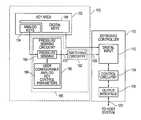
- FIG. 1is a block diagram for a keyboard system 100 including pressure sensitive analog keys 104 and digital keys 106 .
- a keyboard controller 110is coupled through pressure sensing interface circuitry 185 to analog keys 104 of a key area 102 that is part of a keyboard device body.
- the key area 102includes both analog keys 104 and digital keys 106 .
- the digital keys 106represent keys that are momentary on keys that are detected as either depressed or not depressed. When a digital key is depressed, an output signal is sent to an I/O interface in the form of digital input block 112 within the keyboard controller 110 .
- the analog keys 104represent keys that are detected as being depressed by a variable amount or with a variable amount of pressure.
- pressure sensing interface circuitry 185When an analog key is depressed, an indication of the force or extent to which it is depressed is provided to pressure sensing interface circuitry 185 that in the illustrated embodiment includes pressure-sensing digital output circuitry 190 and switching circuitry 192 .
- Pressure sensing interface circuitry 185may be provided in one exemplary embodiment as part of the keyboard device body. However, digital input block 112 and one or more components of pressure sensing interface circuitry 185 may alternatively be integrated within a microcontroller that is operating as the keyboard controller 110 and/or as part of the host system to which the keyboard is connected, if desired. The digital input block 112 and one or more of the components of pressure sensing interface circuitry 185 could also be implemented with external circuitry, as well.
- the pressure-sensing digital output circuitry 190includes a pressure sensing block 198 that receives an analog signal representative of the pressure applied to each of analog keys 104 and then outputs an alternating high and low (high/low) digital output bit stream signal 133 having a frequency that is representative of this pressure being applied to each of analog keys 104 to a corresponding switching element of switching circuitry 192 (e.g., optoisolator, transistor such as MOSFETs, etc.).
- switching circuitry 192e.g., optoisolator, transistor such as MOSFETs, etc.
- Each switching element of switching circuitry 192responds to a digital signal 133 corresponding to a given analog key 104 by providing a toggled alternating open/short (off/on) digital signal 135 to a corresponding intersection point in the 16 ⁇ 8 key matrix which corresponds to that analog key 104 in a manner as described further herein.
- pressure sensing interface circuitry 185may be implemented using any one or more circuitry components suitable for receiving analog signals representative of key pressure from pressure sensitive keys 104 and providing corresponding alternating open/short digital output signals having a toggled frequency that is representative of key pressure from pressure sensitive keys 104 that is suitable, for example, for digital input to a legacy keyboard controller 110 .
- the control circuitry 120 within the keyboard controller 110is coupled to receive on/off signals from the digital input block 112 .
- the control circuitry 120processes this key information and is connected to an output communication interface 118 so that this key information can be communicated to external devices, such as host components of an information handling system, through communication path 122 .
- external devicescan optionally communicate control and/or other configuration information to the keyboard controller though this same output communication interface 118 through communication path 122 . Examples of possible information handling system components may be found described in U.S. patent application Ser. No. 12/586,676, filed Sep. 25, 2009, which is incorporated herein by reference in its entirety.
- the output communication interface 118 and communication path 122can take a variety of forms.
- the communication path 122can be a wired communication path or a wireless communication path, as desired.
- the output communication interface 118will often be a Bluetooth interface if a wireless interface is desired and will often be a USB (universal serial bus) interface if a wired interface is desired.
- USBuniversal serial bus
- any desired communication interfacecan be utilized.
- the keyboard controller 110 and the control circuitry 120can be implemented as a microcontroller (e.g., legacy 8051-based microcontroller or custom microcontroller) that runs firmware stored on a memory device associated with the keyboard controller 110 and/or control circuitry 120 .
- the user configuration information 196can be optionally stored in random access memory (RAM) or other memory storage that is associated with pressure sensing circuitry 190 (either internally or externally).
- RAMrandom access memory
- the configurable analog key control parameters 196can be stored, for example, on a RAM device in the keyboard or on the host system (e.g., on a hard drive) and can provide a wide variety of configurable parameters that can be adjusted by a user through an application programming interface (API) to a software utility application that, for example, has a graphic user interface (GUI) to allow a user to edit the parameters through the software utility.
- APIapplication programming interface
- GUIgraphic user interface
- the user configuration informationmay be stored, for example, in nonvolatile or volatile memory on board the keyboard system 100 .
- the user configuration informationmay be stored on the host system or other device that is coupled by communication path 122 to output interface 118 off keyboard controller.
- the user configuration informationmay be stored on the host system or other device that is coupled by communication path 122 to output interface 118 off keyboard controller.
- single and/or multiple different user configuration files and/or multiple game (or application) configuration filesmay be stored allowing a user to select the applicable or desired keyboard configuration file depending on the game or application being used by the user and/or depending upon the particular user using the keyboard at the time in a manner as described in U.S. patent application Ser. No. 12/316,703 filed Dec. 16, 2008, which is incorporated herein by reference in its entirety.
- FIG. 2is a diagram for an embodiment 200 for key structures including an analog key and a digital key.
- depressing the analog key cap 202causes a variable or analog output 220 to be provided by the keyboard
- depressing digital key cap 203causes a digital or on/off output 222 to be provided by the keyboard.
- the analog keysprovide a variable output
- the digital keysprovide a momentary-on output.
- the embodiment 200has a layered structural approach that is similar to prior techniques except for the use of pressure sensitive keys, such as the capacitive key with a conductive and flexible half-dome structure 216 that is depicted in FIG. 2 .
- This conductive and flexible half-dome structure 216has advantageous operational benefits as described below.
- a base 212represents the bottom of the layered structure and can be made of a material that can support the key structure, such as a hard plastic material.
- a flexible PCB (printed circuit board) 210is then provided on top of the base 212 .
- the PCB 210includes circuit traces or connections that provide for electrical signals to be generated and communicated when keys are depressed.
- circuit connection 236is used to provide digital output 222
- circuit connection pads 230 and 231are used to provide the analog output 220 .
- the next layeris flexible insulator 208 , such as a flexible PCB without circuit connections.
- the next layeris another flexible PCB 206 that can include circuit traces or connections that work in conjunction with the connections on PCB 210 to provide for electrical signals to be generated and communicated when keys are depressed.
- circuit connection 234is used to provide the digital output 222 .
- a relatively thin flexible layer 204can then be provided above PCB 206 and can be made from an injection molded silicon rubber sheet.
- This flexible layer 204is configured to have a molded flexible rubber dome for each key.
- flexible dome 215is provided for analog key cap 202
- flexible dome 213is provided for digital key cap 203 .
- an actuator 214is also provided underneath the dome 213 that causes circuit trace 234 to be engaged with circuit trace 236 when the digital key cap 203 is depressed.
- circuit trace 234 touches the circuit trace 236a signal is now active indicating the key was pressed, causing a digital output 222 to be generated.
- This digital output 222can be configured to provide a momentary-on indication of whether or not the key has been depressed.
- the digital key cap 203can be made from hard plastic.
- a conductive and flexible half-dome 216is provided that flexes when depressed, as described in more detail below, to vary the capacitance associated between circuit pad 231 and circuit pad 230 when analog key cap 202 is depressed.
- pad 231 and pad 230are the two plates of a capacitor. The variable capacitance between these two plates are measured from signal trace 232 by sending this trace to capacitance reading circuitry.
- pad 230can be coupled to ground.
- the conductive and flexible half-dome 216can be made, for example, from a conductive rubber material, that is conductive, flexible and capable of reforming its shape after being depressed and released. Prior art techniques have made this material from a carbon impregnated rubber.
- electrical pad 230is shaped like a donut with an insulative material in the middle.
- Circuit trace 232connects to the circuit pad 231 through a via within the insulative material with the conductive pad 231 being located in the middle of the insulative center of the donut area.
- Pad 230may be attached to a signal trace, but the preferred method of embodiment has pad 230 being coupled to a given charge, such as being attached to ground. Due to insulator layer 208 , the conductive half-dome 216 may only make contact to circuit pad 231 through the hole in the insulator 208 .
- the conductive and flexible half-dome 216makes contact with circuit pad 231 and is deformed by pressure from the analog key cap 202 , the capacitance between pad 231 and pad 230 increases. As more pressure is applied to the analog key cap 202 , the half-dome 216 gradually deforms and flattens-out on top of the insulator, causing a larger conductive surface area to run parallel to pad 230 . Effectively, there are two parallel plates provided by pads 231 and 230 with a fixed thickness insulator/dielectric between them. Pad 230 has a fixed surface area as it is printed onto the PCB 210 .
- pad 231has a variable surface area or is a variable sized parallel plate due to the action of half-dome 216 as it is depressed. As the surface area of pad 231 gradually increases due to action of half-dome 216 as greater force is applied to the analog key cap 202 , the capacitance between plates 231 and 230 gradually increases as well. This variable capacitance can be sensed, measured and used as an indication of the pressure being applied to the analog key cap 202 .
- variable capacitance methodologyover variable resistance is that the sensor is implemented on the PCB directly.
- a sensor materialis required per key that changes impedance when touched. This adds to the keyboard's BOM (build of materials) cost. It also reduces a source of variability of touch performance from PCB to PCB due to the variance of the impedance of printed traces or of the tolerance to passive resistors or other resistive materials used.
- FIG. 3Ais a diagram for different depressed states for the conductive and flexible half-dome structure 216 of FIG. 2 .
- the bottom edge of the half-dome structure 216has a bottom edge position indicated by Line 1 .
- Line 2represents the bottom edge of half-dome structure 216 when it has been depressed some distance.
- Line 3represents the bottom edge of half-dome structure 216 when it has been depressed far enough to touch connection pad 231 through the gap in insulator 208 . It is also noted that bottom edge will have flattened out slightly due to this contact, as shown with respect to Line 3 .
- Line 4shows that the bottom edge of half-dome structure 216 will continue to flatten as it is depressed.
- Line 5is a further indication of this flattening of the half-dome structure 216 . As stated above, as the half-dome structure 216 is moved closer to connection pad 231 , half-dome structure 216 will touch connection pad 231 and will then flatten out causing a larger surface area for electrical plate 231 relative to electrical plate 230 .
- connection pad 231can be coupled to pressure sensing block 198 (of pressure-sensing digital output circuitry 190 ) that operates to sense and measure the electrical information provided from connection pad 231 .
- FIG. 3Bis a diagram for a top view of the capacitive contact pads 230 and 231 for the half-dome structure.
- an insulative material 308sits between the contact pad 230 and the contact pad 231 .
- the contact pad 230can be coupled to ground.
- the variable capacitance (Cx) between the pads 230 and 231 caused by the motion of the half-dome structure 216can be used to provide the analog output 220 .
- the deforming of the half-dome structure 216effectively increases the capacitor plate area associated with the pad 230 , thereby effectively increasing the capacitance between pads 230 and 231 .
- the change in capacitance ( ⁇ C) caused by varying capacitance component (C variable ) due to the half-dome 216can be then used as an indicator of the pressure that has been used to depress the key associated with the half-dome structure 216 .
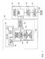
- FIG. 4illustrates one exemplary embodiment of a keyboard system 100 in which analog keys 104 are pressure sensitive capacitive keys as described in relation to FIGS. 2 , 3 A and 3 B, having capacitive pads 231 a - 231 g that are coupled to pressure-sensing digital output circuitry 190 that is implemented by a Texas Instruments 16-bit ultra-low power capacitive sensing microcontroller part number MSP430F2111.
- pressure-sensing digital output circuitry 190is specifically coupled for sensing and measuring capacitance for each key via a corresponding general purpose input output (GPIO) port P 1 . 0 to P 1 . 6 that incorporates a falling edge triggered digital interrupt.
- GPIOgeneral purpose input output
- pressure-sensing digital output circuitry 190employs RC capacitive measurement methodology with falling edge event driven interrupt performed on a per pin basis.
- Information on RC capacitive measurementmay be found, for example, in U.S. Pat. No. 3,936,674, which is incorporated herein by reference in its entirety.
- each capacitive pad 231 a through 231 gis charged and discharged via traces 131 one at a time, and the amount of time for the discharge of each corresponding pad 231 is measured using a timer operating at a high speed (e.g., timer operating at about 16 MHz or other suitable speed).
- pressure-sensing digital output circuitry 190may be implemented by a TI MSP430F2111 microcontroller or other suitable circuitry that employs RC discharge time to measure the variable capacitance of each analog key 104 as follows.
- each signal lines 131acts as a single input/output (I/O) line between a given falling-edge triggered interrupt digital port P 1 .X of pressure-sensing digital output circuitry 190 and a corresponding given analog key 104 .
- the capacitive plate of each analog key 104is also coupled to ground through a resistor 199 (e.g., 6 M ⁇ or other resistor value selected to provide sufficiently slow RC discharge time to provide the desired measurement resolution for the given application).
- each signal line 131is employed to charge, discharge and produce an interrupt when the voltage of the capacitor of analog key 104 crosses a low voltage threshold.
- a given port P 1 .X of a given I/O line 131may be set to output high to charge (e.g., with 500 nA charging current) the capacitive plate of a corresponding analog key 104 to near V CC , and a free-running timer of the pressure-sensing digital output circuitry 190 read to mark the start time.
- the given port P 1 .Xis set to input with negative-edge interrupt enabled and the resistor coupled to the capacitive plate of the corresponding analog key 104 discharges the capacitive plate of the analog key 104 to ground, during which pressure-sensing digital output circuitry 190 may go into low power mode to save power.
- V ILinterrupt voltage
- an interruptis generated which causes the free-running timer to be read again and the elapsed time for discharge of the capacitive plate of the analog key 104 from near V CC to V IL is calculated.
- Pressure-sensing digital output circuitry 190may then return to high power mode.
- the discharge timer count of the capacitive plate of each analog key 104is proportional to its present capacitance, which depends on the amount of pressure currently applied to the key 104 .
- multiple capacitor readings of a given analog key 104may be averaged to filter out common mode noise, e.g., by using a charge cycle followed immediately by a discharge cycle and averaging the two values.
- pressure-sensing digital output circuitry 190provides a corresponding digital output 133 for each capacitive pad 231 and its input 131 .
- Each digital output signal (P 2 . x ) 133corresponds to a respective capacitive pad input (P 1 . x ) 131 .
- each digital output signal 133is produced in an intermittent alternating high/low manner with a frequency that emulates the action of a user's finger toggling away at a conventional digital “momentary on” digital key at a variable speed that is based on the amount of pressure being applied to the corresponding pressure sensitive analog key 104 .
- open/short mechanical user toggling controlmay be advantageously replaced by electrical control based on the key pressure applied by a user to provide a similar intermittent alternating high/low signal output without requiring a user to toggle the keys.
- the exemplary microcontroller of pressure-sensing digital output circuitry 190 of FIG. 4employs 8 digital falling-edge triggered interrupt inputs Port 1 (P 1 . x ), and 8 digital outputs Ports 2 (P 2 . x ), it is possible to select a different chip(s) to support more pressure sensitive keys.
- keyboard system 100is implemented to be interchangeable with a legacy USB keyboard for interconnection with standard 8 bit keyboard controller 110 via a standard 16 ⁇ 8 key matrix 199 with 16 columns ⁇ 8 rows and native device drivers.
- standard 16 ⁇ 8 key matrix 199with 16 columns ⁇ 8 rows and native device drivers.
- one or more features of the disclosed systems and methodsmay be implemented in non-legacy or customized keyboard systems, and in any arrangement of one or more circuitry components as may be suitable for a given application.
- legacy keyboard controller 110has a standard keyboard matrix open/short input 199 provided for the 104 keys on a standard keyboard that is arranged as 16 columns by 8 rows, so that only 24 signals interface with the keyboard controller 110 , rather than a signal line per key which would require over 100 signals to the keyboard controller 110 .
- the keyboard controller 110operates by initially selecting a single row and applying a logic level 1 to it. There are 16 keys in a column, with only one of those keys intersecting with the particular row that's at logic 1. To detect if a key is pressed in a row, each column is sequentially grounded. If a key is pressed, it shorts the column to the row, thus causing the row voltage to drop or go low.
- the keyboard controller 110When the keyboard controller 110 detects the low voltage on the selected row, the pressed key can be determined by the column/row intersection that was electrically shorted. Once all columns have been queried in a single row, the keyboard controller 110 sequences to the next row, and so on until all rows have been queried, thus sampling the logic level for every key.
- switching circuitry 192may be provided as an interface between pressure-sensing digital circuitry 190 and legacy keyboard controller 110 for analog keys 104 . The purpose of the switching circuitry 192 is to convert a high/low digital output stream into a stream of opens/shorts. For example, as shown in FIG.
- a separate optoisolator 180has been provided for each corresponding analog key switch location.
- optoisolatorsinclude, but are not limited to, AVAGO 4N35 or ACPL-227 optocouplers available from Avago Technologies of San Jose, Calif.
- each optoisolator 180provides an electrical control over the make or break (short or open circuit) connection at a given column/row intersection location of keyboard matrix open/short input 198 for that particular key.
- switching circuitry 192allows any key (and/or any number of keys) of a conventional keyboard matrix to be provided with pressure sensing capability.
- FIG. 5illustrates one exemplary embodiment of methodology 500 that may be employed for initialization of pressure-sensing digital output circuitry 190 of keyboard system 100 of FIG. 4 .
- methodology 500starts in step 502 with power up of an information handling system to which keyboard system 100 is coupled.
- the watchdog timeris stopped in step 504 , and timer speed (e.g., digitally controlled crystal oscillator speed) is set in step 506 (e.g., to 16 MHz for TI MSP430F2111 microcontroller).
- timer speede.g., digitally controlled crystal oscillator speed
- step 506e.g., to 16 MHz for TI MSP430F2111 microcontroller. Note that the faster the Timer's clock (e.g., DCO) is running, the more accurate the timing measurement of the RC discharge.
- any embedded low frequency crystal oscillator when presente.g., such as is the case with the TI MSP430F2111
- the I/O pins for this oscillatorcan also function as I/O pins for additional capacitive pads supporting negative edge triggered interrupts.
- these oscillator pinsmay be optionally used as I/O pins to keep the package size (and pin out count) of the microcontroller as small as possible.
- any on-board low speed clockmay be disabled in order to reduce power consumption and eliminate an unnecessary source of electrical noise.
- step 510all I/O pins of pressure-sensing digital output circuitry 190 are initialized to output mode and logic “0” (ground). Then in step 512 , all analog pressure sensitive keys 104 are scanned, one at a time in a sequential or round-robin fashion, by measuring the voltage of each analog key 104 while all other analog keys are grounded. It does this by operating as such:
- a measurement of each of the analog keysmay be performed sequentially (“scanning process”) as labeled in step 512 .
- This scanning processmay be performed multiple times (e.g., 100 times) in order to allow the master clock and PCB conditions to stabilize.
- a base capacitanceis established and tracked, as the base capacitance of the capacitive pad can change due to environmental conditions such as temperature, humidity, voltage drift and/or component tolerances. Note that this is a slow type of change as changes occur in minutes, not microseconds.
- a baseline capacitanceis established as the capacitance of each pad during the open state (when no finger is pressing on the key).
- the base capacitance for each padis updated and stored. If a decrease in capacitance is detected, the software must adjust the base capacitance rapidly since this is not a function of the sensor excitation. We can do this be re-averaging with the current count result. If an increase in capacitance is detected, the base capacitance may be adjusted very slowly as this may be due to a finger hovering over a key, and not because of an environmental drift effect. For example, the base capacitance may be adjusted by 1 with each measurement, but only if no keys are pressed.
- an optional low pass filtermay also help to eliminate the presence of any 50/60 Hz main-power noise that may coupled onto the capacitive pads.
- the low pass noise filtermay be implemented as a software based IIR (infinite impulse response) filter, or essentially as a DC tracking filter.
- step 516sensing for user pressure on each of analog keys 104 is started.
- the endless loop of this sensing processis described further below in relation to FIG. 6 .
- FIG. 6illustrates methodology 600 for sensing, in real time, pressure applied to analog keys 104 , and producing a toggled (alternating open/short) digital signal 133 representative thereof.
- FIG. 6starts in step 602 by taking an averaged capacitance measurement for each pressure sensitive key 104 from signals 131 based on timer counts in a round robin manner as previously described. This may be done by actually taking multiple (e.g., two) measurements at a given pad. If these multiple measurements are conducted in quick succession, the average behaves like a differential measurement, thus helping filter out common-mode noise.
- the baseline countmay be evaluated and updated per pad, as per the rules described above, and run through the low pass filter to generate a filtered count output (also called the adjusted capacitance measurement).
- the present adjusted capacitance measurement value for each key 104is then stored, e.g., in memory of pressure-sensing digital output circuitry 190 .
- all the stored present adjusted capacitance valuesare examined to determine key(s) 104 having a present value of adjusted capacitance that exceeds a pre-determined adjusted capacitance threshold (this is the currently pressed key(s) 104 ).
- step 610the present identity (e.g., key number) of each of the key(s) 104 meeting the threshold adjusted capacitance value is stored along with corresponding present capacitance value(s).
- the key 104 being currently pressedmay be identified as the key 104 having the largest adjusted capacitance measurement of all keys 104 in the current round robin cycle, i.e., rather than using the adjusted capacitance threshold value to determine pressed keys.
- Example code for executing steps 602 - 610is as follows:
- the degree of applied pressure to a presently-pressed keyis next determined, e.g., in a binning operation by comparing the filtered count value to a pre-determined scale of counts per resolution in step 612 based on the stored adjusted capacitance value (or filtered count value) of step 610 . Then, in step 614 , a low active output 133 of pressure-sensing digital output circuitry 190 is toggled that corresponds to the identity of the presently-pressed key (e.g., output P 2 . 1 is toggled for corresponding input P 1 . 1 ).
- This toggled signalmimics or emulates the action of a user repeatedly pressing a conventional digital key 106 for a number of times that is proportional or otherwise relative to the strength of the desired input (i.e. greater pressure on analog key 104 corresponds to more rapid user repeat rate on digital key 106 ).
- alternating toggle rate frequencymay be pre-defined for measured timer counts of a pressed key 104 .
- a maximum toggle ratemay be defined to correspond to a maximum timer count level of 200 with four decreasingly lower toggle rate levels defined for timer counts of 180, 160, 140 and 120, and anything below 120 being disregarded as noise, e.g., toggle rate frequency of 20 times/second for timer count range of 180-200, toggle rate frequency of 16 times/second for timer count range of 160-180, toggle rate frequency of 10 times/second for timer count range of 140-160, toggle rate frequency of 8 times/second for timer count range of 120-140, and no toggling for timer count range of less than 120.
- timer count levels and corresponding timer count valuesare exemplary only and that greater or fewer numbers of timer count levels and/or different timer count values may be employed in other embodiments.
- timer count level embodimentdescribed above:
- step 610 described aboveis optional and only may be employed when the number of analog keys 104 exceeds the number of output lines 133 .
- methodology 600may: pause the round robin measurements whenever a pressed key 104 is identified as exceeding the threshold adjusted capacitance value, determine the degree of applied pressure to pressed key 104 based on its capacitance, and toggle the output signal of the pressed key 104 .
- the count value of the identified pressed key 104may be monitored and reevaluated for as long as it remains pressed by reevaluating the pressed key's timer count by rerunning it through the binning operation to see if the pressure is changed, and outputting an updated digital bit stream signal 133 based thereon.
- the round robin proceduremay resume to the next key 104 and inquire of its count value for this round robin cycle. Either way, the round robin cycle continues for as long as the keyboard system 100 is powered up. After shut down, the pressure-sensing digital output circuitry 190 may be reset on next power up, all keys reinitialized (e.g., per FIG. 5 ), and the round robin key capacitance measurement routine initialized again.
Landscapes
- Engineering & Computer Science (AREA)
- General Engineering & Computer Science (AREA)
- Theoretical Computer Science (AREA)
- Human Computer Interaction (AREA)
- Physics & Mathematics (AREA)
- General Physics & Mathematics (AREA)
- Input From Keyboards Or The Like (AREA)
Abstract
Description
- 1. The I/O pin is set to output high. A Timer is read to mark the start time.
- 2. The I/O pin is set to input mode with negative edge interrupt enabled. The resistor then discharges the capacitive pad. The TI MSP430 microcontroller goes into low power mode for reduced power consumption, however, it's still able to monitor the interrupt enabled input I/O pins.
- 3. When the voltage of the sensor crosses the low level voltage threshold, an interrupt is generated.
- 4. The interrupt service routine (ISR) reads the Timer and calculates the time to discharge to the low voltage threshold level. This is referred to as a “count” value. The MSP430 exits low power mode and continues operation.
| /* TAKE MEASUREMENT ON 4 CAPACITIVE PADS */ |
| int scan_keys(void) |
| { |
| int i; | |
| int margin; | |
| for (i = 0; i < NUM_LINES; i++) | |
| { |
| /* take pad measurement and establish */ |
| margin = measure_key_capacitance(i) − key_line[i].base_capacitance; |
| /* convert measurement to filtered value using a single pole IIR low pass |
| filter */ | |
| key_line[i].filtered += (margin − (key_line[i].filtered >> 4)); |
| /* KEY_LINE[I].FILTERED IS OUR “COUNT” WE WANT TO USE */ |
| } | |
| return 0; |
| } |
| /* FIGURE OUT WHICH KEY LINE IS PRESSED ON (IF ANY) */ |
| int find_finger_position(void) |
| { |
| int i; | |
| int min; | |
| int max; | |
| int max_pos; | |
| /* Find the minimum and maximum responses for all the 4 key lines */ | |
| min = 32767; | |
| max = −32768; | |
| max_pos = −1; | |
| for (i = 0; i < NUM_LINES; i++) | |
| { |
| if (key_line[i].filtered < min) |
| min = key_line[i].filtered; |
| if (key_line[i].filtered > max) | |
| { |
| max = key_line[i].filtered; | |
| max_pos = i; |
| } |
| } | |
| /* If the maximum response isn't that big, there is no finger present. */ | |
| if (max < 200) | |
| { |
| P1OUT &= 0xCF; /* no key pressed = “00” (P1.5, P1.4) */ | |
| P1DIR |= 0x30; | |
| return 0; |
| } | |
| /*P1.5, P1.4 are the 2 bit output pins*/ | |
| /* TRUTH TABLE BELOW FOR KEY PRESS */ | |
| /* P1.5 P1.4 |
| 0 0 NO KEY IS PRESSED | |
| 1 0 P1.0 IS PRESSED | |
| 1 1 P1.2 IS PRESSED | |
| 0 1 P1.3 IS PRESSED |
| */ | |
| if (max_pos == 0) | |
| { |
| P1OUT |= 0x20; /* P1.0 IS PRESSED = “10” */ | |
| P1OUT &= 0xEF; | |
| P1DIR |= 0x30; | |
| return max; |
| } | |
| if (max_pos == 2) | |
| { |
| P1OUT |= 0x30; /* P1.2 IS PRESSED = “11” */ | |
| P1DIR |= 0x30; | |
| return max; |
| } | |
| if (max_pos == 3) | |
| { |
| P1OUT &= 0xDF; /* P1.3 IS PRESSED = “01” */ | |
| P1OUT |= 0x10; | |
| P1DIR |= 0x30; | |
| return max; |
| } | |
| if (max_pos == 1) | |
| { |
| P1OUT &= 0xCF; /* otherwise = “00” */ | |
| P1DIR |= 0x30; | |
| return 0; |
| } | |
| else | |
| { |
| P1OUT &= 0xCF; /* otherwise = “00” */ | |
| P1DIR |= 0x30; | |
| return 0; |
| } |
| } |
| int pressed_key_pressure = 0; |
| void main(void) |
| { |
| . |
| . |
| . |
| /* INITIALIZE ALL PADS TO BE SCANNED TO GROUND */ |
| for (i = 0; i < NUM_LINES; i++) |
| init_key(&key_line[i], &key_line_config[i]); |
| TACTL = TASSEL_2 | MC_2; // | ID_3; | |
| /* Scan the | |
| conditions to stablise */ | |
| for (i = 0; i < 100; i++) |
| scan_keys( ); |
| /* Establish base capacitance and filtered “count” per active pad */ | |
| for (i = 0; i < NUM_LINES; i++) | |
| { |
| key_line[i].base_capacitance = key_line[i].filtered >> 4; | |
| key_line[i].filtered = 0; |
| } | |
| for (;;) | |
| { |
| scan_keys( ); | |
| if ((pressed_key_pressure = find_finger_position( )) > 0) | |
| { |
| /* There is a finger on the pad */ | |
| send_to_host(pressed_key_pressure); |
| } | |
| else | |
| { |
| /* There is no finger on the pad */ | |
| send_to_host(0); |
| } |
| } |
| } |
| if (count > 180) |
| for (num_toggles = 20; num_toggles >0 ; num_toggles−−) |
| { |
| P2OUT {circumflex over ( )}= 0x02; /*Toggle P2.1 low 10 times in | |
| 1 sec */ | |
| /* loop provides delay of 0.05 sec/.000017922 sec = 2789 | |
| loops */ | |
| for (loop=2789; loop>0; loop − −); | |
| } |
| else if ((count > 160) && (count <= 180)) |
| for (num_toggles=16; num_toggles>0; num_toggles − −) |
| { |
| P2OUT {circumflex over ( )}= 0x02; /*Toggle P2.1 low 8 times in | |
| 1 sec */ | |
| /* loop provides delay of 0.0625 sec/.000017922 sec = | |
| 3487 loops */ | |
| for (loop=3487; loop>0; loop − −); | |
| } |
| else if ((count > 140) && (count <= 160)) |
| for (num_toggles=10; num_toggles>0; num_toggles − −) |
| { |
| P2OUT {circumflex over ( )}= 0x02; /*Toggle P2.1 low 5 times in | |
| 1 sec */ | |
| /* loop provides delay of 0.1 sec/.000017922 sec = | |
| 5579 loops */ | |
| for (loop=5579; loop>0; loop − −); | |
| } |
| else if ((count > 120) && (count <= 140)) |
| for (num_toggles=4; num_toggles>0; num_toggles − −) |
| { |
| P2OUT {circumflex over ( )}= 0x02; /*Toggle P2.1 low 2 times | |
| in 1 sec */ | |
| /*loop provides delay of 0.25 sec/.000017922 sec = | |
| 13949 loops */ | |
| for (loop=13949; loop>0; loop − −); | |
| } |
| else |
| { |
| / * DO NOTHING. KEY IS NOT PRESSED ON */ |
| } | ||
Claims (32)
Priority Applications (4)
| Application Number | Priority Date | Filing Date | Title |
|---|---|---|---|
| US12/802,468US8711011B2 (en) | 2008-12-16 | 2010-06-08 | Systems and methods for implementing pressure sensitive keyboards |
| US12/930,125US8674941B2 (en) | 2008-12-16 | 2010-12-29 | Systems and methods for implementing haptics for pressure sensitive keyboards |
| US12/930,118US8760273B2 (en) | 2008-12-16 | 2010-12-29 | Apparatus and methods for mounting haptics actuation circuitry in keyboards |
| US14/044,331US9342149B2 (en) | 2008-12-16 | 2013-10-02 | Systems and methods for implementing haptics for pressure sensitive keyboards |
Applications Claiming Priority (2)
| Application Number | Priority Date | Filing Date | Title |
|---|---|---|---|
| US12/316,703US9246487B2 (en) | 2008-12-16 | 2008-12-16 | Keyboard with user configurable granularity scales for pressure sensitive keys |
| US12/802,468US8711011B2 (en) | 2008-12-16 | 2010-06-08 | Systems and methods for implementing pressure sensitive keyboards |
Related Parent Applications (1)
| Application Number | Title | Priority Date | Filing Date |
|---|---|---|---|
| US12/316,703Continuation-In-PartUS9246487B2 (en) | 2008-12-16 | 2008-12-16 | Keyboard with user configurable granularity scales for pressure sensitive keys |
Related Child Applications (2)
| Application Number | Title | Priority Date | Filing Date |
|---|---|---|---|
| US12/930,125Continuation-In-PartUS8674941B2 (en) | 2008-12-16 | 2010-12-29 | Systems and methods for implementing haptics for pressure sensitive keyboards |
| US12/930,118Continuation-In-PartUS8760273B2 (en) | 2008-12-16 | 2010-12-29 | Apparatus and methods for mounting haptics actuation circuitry in keyboards |
Publications (2)
| Publication Number | Publication Date |
|---|---|
| US20100321301A1 US20100321301A1 (en) | 2010-12-23 |
| US8711011B2true US8711011B2 (en) | 2014-04-29 |
Family
ID=43353869
Family Applications (1)
| Application Number | Title | Priority Date | Filing Date |
|---|---|---|---|
| US12/802,468Active2029-09-21US8711011B2 (en) | 2008-12-16 | 2010-06-08 | Systems and methods for implementing pressure sensitive keyboards |
Country Status (1)
| Country | Link |
|---|---|
| US (1) | US8711011B2 (en) |
Cited By (5)
| Publication number | Priority date | Publication date | Assignee | Title |
|---|---|---|---|---|
| US20130162452A1 (en)* | 2011-12-22 | 2013-06-27 | Tzu-Hung Wang | Apparatus for performing key control with reduced key matrix pin count |
| US10775850B2 (en) | 2017-07-26 | 2020-09-15 | Apple Inc. | Computer with keyboard |
| US11324093B1 (en)* | 2021-01-15 | 2022-05-03 | Dell Products L.P. | Adjusting underlighting of a keyboard input device |
| US20220283629A1 (en)* | 2019-03-27 | 2022-09-08 | Liquid Wire Inc. | Deformable human interface device |
| US11463091B2 (en) | 2018-12-13 | 2022-10-04 | Razer (Asia-Pacific) Pte. Ltd. | Analog input device, computing system and method for receiving and processing analog input |
Families Citing this family (94)
| Publication number | Priority date | Publication date | Assignee | Title |
|---|---|---|---|---|
| US8674941B2 (en) | 2008-12-16 | 2014-03-18 | Dell Products, Lp | Systems and methods for implementing haptics for pressure sensitive keyboards |
| US8711011B2 (en)* | 2008-12-16 | 2014-04-29 | Dell Products, Lp | Systems and methods for implementing pressure sensitive keyboards |
| US9246487B2 (en) | 2008-12-16 | 2016-01-26 | Dell Products Lp | Keyboard with user configurable granularity scales for pressure sensitive keys |
| US20120092263A1 (en)* | 2009-10-15 | 2012-04-19 | Pacinian Corporation | Haptic keyboard featuring a satisfying tactile keypress experience |
| GB2482190A (en)* | 2010-07-23 | 2012-01-25 | New Transducers Ltd | Methods of generating a desired haptic sensation in a touch sensitive device |
| US8735755B2 (en) | 2011-03-07 | 2014-05-27 | Synaptics Incorporated | Capacitive keyswitch technologies |
| US8748767B2 (en) | 2011-05-27 | 2014-06-10 | Dell Products Lp | Sub-membrane keycap indicator |
| US9417754B2 (en) | 2011-08-05 | 2016-08-16 | P4tents1, LLC | User interface system, method, and computer program product |
| US8700829B2 (en) | 2011-09-14 | 2014-04-15 | Dell Products, Lp | Systems and methods for implementing a multi-function mode for pressure sensitive sensors and keyboards |
| US9354748B2 (en) | 2012-02-13 | 2016-05-31 | Microsoft Technology Licensing, Llc | Optical stylus interaction |
| US8873227B2 (en) | 2012-03-02 | 2014-10-28 | Microsoft Corporation | Flexible hinge support layer |
| US9460029B2 (en) | 2012-03-02 | 2016-10-04 | Microsoft Technology Licensing, Llc | Pressure sensitive keys |
| USRE48963E1 (en) | 2012-03-02 | 2022-03-08 | Microsoft Technology Licensing, Llc | Connection device for computing devices |
| US9075566B2 (en) | 2012-03-02 | 2015-07-07 | Microsoft Technoogy Licensing, LLC | Flexible hinge spine |
| US9298236B2 (en) | 2012-03-02 | 2016-03-29 | Microsoft Technology Licensing, Llc | Multi-stage power adapter configured to provide a first power level upon initial connection of the power adapter to the host device and a second power level thereafter upon notification from the host device to the power adapter |
| US9360893B2 (en) | 2012-03-02 | 2016-06-07 | Microsoft Technology Licensing, Llc | Input device writing surface |
| US9426905B2 (en) | 2012-03-02 | 2016-08-23 | Microsoft Technology Licensing, Llc | Connection device for computing devices |
| US9064654B2 (en) | 2012-03-02 | 2015-06-23 | Microsoft Technology Licensing, Llc | Method of manufacturing an input device |
| US9870066B2 (en) | 2012-03-02 | 2018-01-16 | Microsoft Technology Licensing, Llc | Method of manufacturing an input device |
| WO2013169875A2 (en) | 2012-05-09 | 2013-11-14 | Yknots Industries Llc | Device, method, and graphical user interface for displaying content associated with a corresponding affordance |
| AU2013259630B2 (en) | 2012-05-09 | 2016-07-07 | Apple Inc. | Device, method, and graphical user interface for transitioning between display states in response to gesture |
| EP2847662B1 (en) | 2012-05-09 | 2020-02-19 | Apple Inc. | Device, method, and graphical user interface for providing feedback for changing activation states of a user interface object |
| CN108958550B (en) | 2012-05-09 | 2021-11-12 | 苹果公司 | Device, method and graphical user interface for displaying additional information in response to user contact |
| WO2013169849A2 (en) | 2012-05-09 | 2013-11-14 | Industries Llc Yknots | Device, method, and graphical user interface for displaying user interface objects corresponding to an application |
| WO2013169851A2 (en) | 2012-05-09 | 2013-11-14 | Yknots Industries Llc | Device, method, and graphical user interface for facilitating user interaction with controls in a user interface |
| WO2013169843A1 (en) | 2012-05-09 | 2013-11-14 | Yknots Industries Llc | Device, method, and graphical user interface for manipulating framed graphical objects |
| EP3410287B1 (en) | 2012-05-09 | 2022-08-17 | Apple Inc. | Device, method, and graphical user interface for selecting user interface objects |
| WO2013169842A2 (en) | 2012-05-09 | 2013-11-14 | Yknots Industries Llc | Device, method, and graphical user interface for selecting object within a group of objects |
| WO2013169865A2 (en) | 2012-05-09 | 2013-11-14 | Yknots Industries Llc | Device, method, and graphical user interface for moving a user interface object based on an intensity of a press input |
| WO2013169845A1 (en) | 2012-05-09 | 2013-11-14 | Yknots Industries Llc | Device, method, and graphical user interface for scrolling nested regions |
| HK1208275A1 (en) | 2012-05-09 | 2016-02-26 | 苹果公司 | Device, method, and graphical user interface for moving and dropping a user interface object |
| CN108241465B (en) | 2012-05-09 | 2021-03-09 | 苹果公司 | Method and apparatus for providing haptic feedback for operations performed in a user interface |
| US20130300590A1 (en) | 2012-05-14 | 2013-11-14 | Paul Henry Dietz | Audio Feedback |
| US9063693B2 (en) | 2012-06-13 | 2015-06-23 | Microsoft Technology Licensing, Llc | Peripheral device storage |
| US9684382B2 (en) | 2012-06-13 | 2017-06-20 | Microsoft Technology Licensing, Llc | Input device configuration having capacitive and pressure sensors |
| US9073123B2 (en) | 2012-06-13 | 2015-07-07 | Microsoft Technology Licensing, Llc | Housing vents |
| US20130346636A1 (en)* | 2012-06-13 | 2013-12-26 | Microsoft Corporation | Interchangeable Surface Input Device Mapping |
| US9459160B2 (en) | 2012-06-13 | 2016-10-04 | Microsoft Technology Licensing, Llc | Input device sensor configuration |
| US9240296B2 (en) | 2012-08-06 | 2016-01-19 | Synaptics Incorporated | Keyboard construction having a sensing layer below a chassis layer |
| US9218927B2 (en) | 2012-08-06 | 2015-12-22 | Synaptics Incorporated | Touchsurface assembly with level and planar translational responsiveness via a buckling elastic component |
| US9040851B2 (en) | 2012-08-06 | 2015-05-26 | Synaptics Incorporated | Keycap assembly with an interactive spring mechanism |
| US9177733B2 (en) | 2012-08-06 | 2015-11-03 | Synaptics Incorporated | Touchsurface assemblies with linkages |
| WO2014025786A1 (en) | 2012-08-06 | 2014-02-13 | Synaptics Incorporated | Touchsurface assembly utilizing magnetically enabled hinge |
| US8964379B2 (en) | 2012-08-20 | 2015-02-24 | Microsoft Corporation | Switchable magnetic lock |
| US9389711B2 (en) | 2012-12-21 | 2016-07-12 | Dell Products, Lp | Architecture for variable pressure mouse |
| KR102001332B1 (en) | 2012-12-29 | 2019-07-17 | 애플 인크. | Device, method, and graphical user interface for determining whether to scroll or select contents |
| WO2014105279A1 (en) | 2012-12-29 | 2014-07-03 | Yknots Industries Llc | Device, method, and graphical user interface for switching between user interfaces |
| CN105144057B (en) | 2012-12-29 | 2019-05-17 | 苹果公司 | For moving the equipment, method and graphic user interface of cursor according to the cosmetic variation of the control icon with simulation three-dimensional feature |
| WO2014105276A1 (en) | 2012-12-29 | 2014-07-03 | Yknots Industries Llc | Device, method, and graphical user interface for transitioning between touch input to display output relationships |
| CN105264479B (en) | 2012-12-29 | 2018-12-25 | 苹果公司 | Apparatus, method and graphical user interface for navigating a user interface hierarchy |
| KR101755029B1 (en) | 2012-12-29 | 2017-07-06 | 애플 인크. | Device, method, and graphical user interface for forgoing generation of tactile output for a multi-contact gesture |
| US9176538B2 (en) | 2013-02-05 | 2015-11-03 | Microsoft Technology Licensing, Llc | Input device configurations |
| US10578499B2 (en) | 2013-02-17 | 2020-03-03 | Microsoft Technology Licensing, Llc | Piezo-actuated virtual buttons for touch surfaces |
| US9343248B2 (en) | 2013-08-29 | 2016-05-17 | Dell Products Lp | Systems and methods for implementing spring loaded mechanical key switches with variable displacement sensing |
| US9368300B2 (en) | 2013-08-29 | 2016-06-14 | Dell Products Lp | Systems and methods for lighting spring loaded mechanical key switches |
| US9448631B2 (en) | 2013-12-31 | 2016-09-20 | Microsoft Technology Licensing, Llc | Input device haptics and pressure sensing |
| US9781801B2 (en) | 2014-01-06 | 2017-10-03 | Dell Products, Lp | Performance lighting and control method |
| US10804897B2 (en)* | 2014-01-10 | 2020-10-13 | Touchplus Information Corp. | Touch-sensitive keypad control device |
| US9111005B1 (en) | 2014-03-13 | 2015-08-18 | Dell Products Lp | Systems and methods for configuring and controlling variable pressure and variable displacement sensor operations for information handling systems |
| US10120420B2 (en) | 2014-03-21 | 2018-11-06 | Microsoft Technology Licensing, Llc | Lockable display and techniques enabling use of lockable displays |
| US9696793B2 (en) | 2014-05-06 | 2017-07-04 | Dell Products L.P. | Systems and methods for selectably suppressing computing input events triggered by variable pressure and variable displacement sensors |
| US10324733B2 (en) | 2014-07-30 | 2019-06-18 | Microsoft Technology Licensing, Llc | Shutdown notifications |
| US10545545B2 (en) | 2014-07-31 | 2020-01-28 | Dell Products, Lp | Triangular system for modifiable thermal control |
| US9395765B2 (en) | 2014-07-31 | 2016-07-19 | Dell Products, Lp | Unibody construction triangular chassis |
| US10008760B2 (en) | 2014-07-31 | 2018-06-26 | Dell Products, Lp | Antenna method and apparatus |
| US9424048B2 (en) | 2014-09-15 | 2016-08-23 | Microsoft Technology Licensing, Llc | Inductive peripheral retention device |
| CN104571766B (en)* | 2015-01-19 | 2019-11-19 | 深圳市力驰创新科技有限公司 | The input operating method of input unit |
| WO2016115946A1 (en)* | 2015-01-19 | 2016-07-28 | 黄俭安 | Input apparatus and input operation method therefor |
| US9645732B2 (en) | 2015-03-08 | 2017-05-09 | Apple Inc. | Devices, methods, and graphical user interfaces for displaying and using menus |
| US9632664B2 (en) | 2015-03-08 | 2017-04-25 | Apple Inc. | Devices, methods, and graphical user interfaces for manipulating user interface objects with visual and/or haptic feedback |
| US9990107B2 (en) | 2015-03-08 | 2018-06-05 | Apple Inc. | Devices, methods, and graphical user interfaces for displaying and using menus |
| US10048757B2 (en) | 2015-03-08 | 2018-08-14 | Apple Inc. | Devices and methods for controlling media presentation |
| US10095396B2 (en) | 2015-03-08 | 2018-10-09 | Apple Inc. | Devices, methods, and graphical user interfaces for interacting with a control object while dragging another object |
| US9639184B2 (en) | 2015-03-19 | 2017-05-02 | Apple Inc. | Touch input cursor manipulation |
| US9785305B2 (en) | 2015-03-19 | 2017-10-10 | Apple Inc. | Touch input cursor manipulation |
| US10152208B2 (en) | 2015-04-01 | 2018-12-11 | Apple Inc. | Devices and methods for processing touch inputs based on their intensities |
| US20170045981A1 (en) | 2015-08-10 | 2017-02-16 | Apple Inc. | Devices and Methods for Processing Touch Inputs Based on Their Intensities |
| US10222889B2 (en) | 2015-06-03 | 2019-03-05 | Microsoft Technology Licensing, Llc | Force inputs and cursor control |
| US10416799B2 (en) | 2015-06-03 | 2019-09-17 | Microsoft Technology Licensing, Llc | Force sensing and inadvertent input control of an input device |
| US9891811B2 (en) | 2015-06-07 | 2018-02-13 | Apple Inc. | Devices and methods for navigating between user interfaces |
| US9860451B2 (en) | 2015-06-07 | 2018-01-02 | Apple Inc. | Devices and methods for capturing and interacting with enhanced digital images |
| US9830048B2 (en) | 2015-06-07 | 2017-11-28 | Apple Inc. | Devices and methods for processing touch inputs with instructions in a web page |
| US10200598B2 (en) | 2015-06-07 | 2019-02-05 | Apple Inc. | Devices and methods for capturing and interacting with enhanced digital images |
| US10346030B2 (en) | 2015-06-07 | 2019-07-09 | Apple Inc. | Devices and methods for navigating between user interfaces |
| US10248308B2 (en) | 2015-08-10 | 2019-04-02 | Apple Inc. | Devices, methods, and graphical user interfaces for manipulating user interfaces with physical gestures |
| US9880735B2 (en) | 2015-08-10 | 2018-01-30 | Apple Inc. | Devices, methods, and graphical user interfaces for manipulating user interface objects with visual and/or haptic feedback |
| US10235035B2 (en) | 2015-08-10 | 2019-03-19 | Apple Inc. | Devices, methods, and graphical user interfaces for content navigation and manipulation |
| US10416800B2 (en) | 2015-08-10 | 2019-09-17 | Apple Inc. | Devices, methods, and graphical user interfaces for adjusting user interface objects |
| US10061385B2 (en) | 2016-01-22 | 2018-08-28 | Microsoft Technology Licensing, Llc | Haptic feedback for a touch input device |
| US11500538B2 (en)* | 2016-09-13 | 2022-11-15 | Apple Inc. | Keyless keyboard with force sensing and haptic feedback |
| AU2017436073B2 (en) | 2017-10-20 | 2023-10-12 | Razer (Asia-Pacific) Pte. Ltd. | User input devices and methods for identifying a user input in a user input device |
| CN112073047B (en)* | 2020-09-09 | 2024-08-16 | 上海东软载波微电子有限公司 | Capacitive touch key system and control method thereof |
| CN114446665A (en)* | 2022-01-19 | 2022-05-06 | 童宗伟 | Variable capacitance device, implementation method and pressure switch device |
| GB2633763A (en)* | 2023-09-19 | 2025-03-26 | Peratech Ip Ltd | Force sensor apparatus and keyboard |
Citations (83)
| Publication number | Priority date | Publication date | Assignee | Title |
|---|---|---|---|---|
| US3936674A (en) | 1974-03-05 | 1976-02-03 | Sandoz, Inc. | Rate signal generator circuit |
| US4291201A (en)* | 1979-04-09 | 1981-09-22 | American Telecommunications Corporation | Push-button dial assembly for telephones |
| US4302011A (en) | 1976-08-24 | 1981-11-24 | Peptek, Incorporated | Video game apparatus and method |
| US4303811A (en)* | 1979-12-03 | 1981-12-01 | W. H. Brady Co. | Kit for use in the construction of custom prototype membrane switch panels |
| US4334134A (en) | 1980-11-13 | 1982-06-08 | Gte Automatic Electric Labs Inc. | Identification cap actuator assembly |
| US4449024A (en) | 1983-05-03 | 1984-05-15 | Kb Denver, Inc. | Backlighted illuminated keyboard |
| US4527250A (en) | 1980-09-11 | 1985-07-02 | Allen-Bradley Company | Video computer terminal with detachable intelligent keyboard module |
| US4733590A (en)* | 1984-12-04 | 1988-03-29 | Nippon Gakki Seizo Kabushiki Kaisha | Keyboard switch apparatus for electronic musical instrument |
| US4896069A (en) | 1988-05-27 | 1990-01-23 | Makash - Advanced Piezo Technology | Piezoelectric switch |
| US4899631A (en) | 1988-05-24 | 1990-02-13 | Baker Richard P | Active touch keyboard |
| US4977298A (en)* | 1989-09-08 | 1990-12-11 | Matsushita Electric Industrial Co., Ltd. | Panel switch |
| US5220318A (en)* | 1988-12-22 | 1993-06-15 | Ampex Corporation | Apparatus for selectively varying keyboard switching force |
| US5252798A (en) | 1990-11-15 | 1993-10-12 | Alps Electric Co., Ltd. | Illuminated switch apparatus |
| US5285037A (en) | 1992-04-10 | 1994-02-08 | Ampex Systems Corp. | Illuminated dome switch |
| US5408060A (en) | 1991-01-29 | 1995-04-18 | Nokia Mobile Phones Ltd. | Illuminated pushbutton keyboard |
| US5434566A (en)* | 1991-06-10 | 1995-07-18 | Fujitsu Limited | Key touch adjusting method and device |
| US5450078A (en) | 1992-10-08 | 1995-09-12 | Intellitools, Inc. | Membrane computer keyboard and method |
| US5909211A (en) | 1997-03-25 | 1999-06-01 | International Business Machines Corporation | Touch pad overlay driven computer system |
| US6007209A (en) | 1997-03-19 | 1999-12-28 | Teledyne Industries, Inc. | Light source for backlighting |
| US6102802A (en) | 1997-10-01 | 2000-08-15 | Armstrong; Brad A. | Game controller with analog pressure sensor(s) |
| US6135886A (en) | 1997-10-01 | 2000-10-24 | Armstrong; Brad A. | Variable-conductance sensor with elastomeric dome-cap |
| US6275138B1 (en) | 1999-06-10 | 2001-08-14 | Alps Electric Co., Ltd. | Variable resistor changing resistance value by pressing |
| US20020084721A1 (en) | 2001-01-03 | 2002-07-04 | Walczak Thomas J. | Piezo electric keypad assembly with tactile feedback |
| US20030072595A1 (en) | 2001-10-16 | 2003-04-17 | Ziad Al-Safar | Lighted computer keyboard |
| US6559399B2 (en) | 2001-04-11 | 2003-05-06 | Darfon Electronics Corp. | Height-adjusting collapsible mechanism for a button key |
| US6608271B2 (en) | 2001-08-17 | 2003-08-19 | Danger, Inc. | Method of dynamically lighting keyboard glyphs |
| US20030210233A1 (en)* | 2002-05-13 | 2003-11-13 | Touch Controls, Inc. | Computer user interface input device and a method of using same |
| US6684166B2 (en) | 2002-05-02 | 2004-01-27 | International Business Machines Corporation | Pressure sensitive keyboard |
| US20040027385A1 (en)* | 2001-02-19 | 2004-02-12 | Junichi Rekimoto | Information input device |
| US6747867B2 (en) | 2000-12-08 | 2004-06-08 | Darfon Electronics Corp. | Elevated and lower keyboard apparatus |
| US6758615B2 (en) | 2001-09-05 | 2004-07-06 | Logitech Europe S.A. | Pressure sensitive functionality for keyboard keys |
| US20040174200A1 (en) | 2003-02-26 | 2004-09-09 | Mcnutt Alan D. | Pulse output function for programmable logic controller with linear frequency change |
| US20040183783A1 (en) | 2003-03-19 | 2004-09-23 | International Business Machines Corp. | Method and apparatus for improved keyboard accessibility using vibrating keys |
| US6860612B2 (en) | 2001-11-30 | 2005-03-01 | Darfon Electronics Corp | Illuminated keyboard switch structure |
| US20050057514A1 (en) | 2003-09-16 | 2005-03-17 | Microsoft Corporation | Quantitatively force-sensing computer keyboard |
| US20050057515A1 (en) | 2003-09-16 | 2005-03-17 | Microsoft Corporation | Computer keyboard with quantitatively force-sensing keys |
| US20050073446A1 (en) | 2003-10-06 | 2005-04-07 | Mihal Lazaridis | Selective keyboard illumination |
| US6883985B2 (en) | 2002-02-26 | 2005-04-26 | Robin Catherine Roberson | Printable, reusable key masks |
| US6918677B2 (en) | 1999-09-15 | 2005-07-19 | Michael Shipman | Illuminated keyboard |
| US20060022951A1 (en) | 2004-08-02 | 2006-02-02 | Infinium Labs, Inc. | Method and apparatus for backlighting of a keyboard for use with a game device |
| US7059790B2 (en)* | 2003-11-14 | 2006-06-13 | Tareq Risheq | Keyboard and method of making the same |
| US20060148564A1 (en) | 2005-01-06 | 2006-07-06 | Bfg Technologies, Inc. | Game control system |
| US7106305B2 (en) | 1999-12-07 | 2006-09-12 | Immersion Corporation | Haptic feedback using a keyboard device |
| US20060277466A1 (en) | 2005-05-13 | 2006-12-07 | Anderson Thomas G | Bimodal user interaction with a simulated object |
| US20070065215A1 (en) | 2005-04-18 | 2007-03-22 | Ronald Brown | Display-equipped key,key assembly, device and method |
| US7244898B2 (en) | 2004-03-05 | 2007-07-17 | Lg Electronics Inc. | Button assembly for home appliance |
| US20070227256A1 (en) | 2006-03-31 | 2007-10-04 | Cypress Semiconductor Corporation | Method and apparatus for sensing the force with which a button is pressed |
| US20070235307A1 (en) | 2003-03-04 | 2007-10-11 | Darfon Electronics Corp. | Keyboard structure |
| US20070285393A1 (en) | 2003-12-15 | 2007-12-13 | Mark Ishakov | Universal Multifunctional Key for Input/Output Devices |
| US7335844B2 (en) | 2006-03-03 | 2008-02-26 | Samsung Electronics Co., Ltd. | Keypad assembly for electronic device |
| US20080092087A1 (en) | 2005-09-19 | 2008-04-17 | Ronald Brown | Method and Display Data Entry Unit |
| US7394033B2 (en) | 2003-08-26 | 2008-07-01 | Lg Electronics Inc. | Control panel assembly and method for controlling thereof |
| US20080179172A1 (en) | 2007-01-31 | 2008-07-31 | Hewlett-Packard Development Company, L.P. | System for illuminating a keycap on a keyboard |
| US20080251364A1 (en) | 2007-04-11 | 2008-10-16 | Nokia Corporation | Feedback on input actuator |
| US20090007758A1 (en) | 2007-07-06 | 2009-01-08 | James William Schlosser | Haptic Keyboard Systems and Methods |
| US20090079612A1 (en) | 2007-09-21 | 2009-03-26 | Siemens Energy & Automation, Inc. | Systems and/or Devices for Providing an Isolated Analog Output or Analog Input |
| US20090127084A1 (en) | 2007-11-16 | 2009-05-21 | Dell Products L.P. | Illuminated Indicator On An Input Device |
| US20090140985A1 (en) | 2007-11-30 | 2009-06-04 | Eric Liu | Computing device that determines and uses applied pressure from user interaction with an input interface |
| US20090178913A1 (en) | 2007-07-06 | 2009-07-16 | Cody George Peterson | Haptic Keyboard Systems and Methods |
| US20090189873A1 (en) | 2008-01-29 | 2009-07-30 | Cody George Peterson | Projected Field Haptic Actuation |
| US20090189790A1 (en) | 2007-07-06 | 2009-07-30 | Cody George Peterson | Haptic Keyboard Systems and Methods |
| US20090207055A1 (en) | 2003-09-16 | 2009-08-20 | Microsoft Corporation | Method for processing data quantifying force applied to one or more keys of a computer keyboard |
| US7655901B2 (en) | 2005-11-18 | 2010-02-02 | Research In Motion Limited | Light assisted keyboard for mobile communication device |
| US20100027854A1 (en) | 2008-07-31 | 2010-02-04 | Manjirnath Chatterjee | Multi-purpose detector-based input feature for a computing device |
| US7667371B2 (en) | 2007-09-17 | 2010-02-23 | Motorola, Inc. | Electronic device and circuit for providing tactile feedback |
| US20100090813A1 (en) | 2008-10-10 | 2010-04-15 | Richard Je | Electronic Device with Localized Haptic Response |
| US20100089735A1 (en) | 2008-04-17 | 2010-04-15 | Minebea Co., Ltd. | Haptic keyboard apparatus and method |
| US20100090814A1 (en) | 2008-10-10 | 2010-04-15 | Adam Cybart | Electronic Device with Suspension Interface for Localized Haptic Response |
| US20100117809A1 (en) | 2008-11-11 | 2010-05-13 | Motorola Inc. | Display module with piezoelectric haptics |
| US7772987B2 (en) | 2007-11-08 | 2010-08-10 | Dell Products L.P. | Lighting control framework |
| US20100205803A1 (en) | 2007-06-29 | 2010-08-19 | Artificial Muscle, Inc. | Electroactive polymer transducers for sensory feedback applications |
| US20100253552A1 (en) | 2007-07-17 | 2010-10-07 | Senentxu Lanceros Mendez | Keyboard based in polymer, copolymer or composites with piezo- and/or pyroelectric properties and respective use |
| US20100288607A1 (en) | 2007-11-16 | 2010-11-18 | Dell Products L.P. | Illuminated indicator on an input device |
| US20100321301A1 (en)* | 2008-12-16 | 2010-12-23 | Casparian Mark A | Systems and methods for implementing pressure sensitive keyboards |
| US20110102325A1 (en) | 2009-11-05 | 2011-05-05 | Minebea Co., Ltd. | Keyboard device and electronic equipment using same |
| US20110102340A1 (en)* | 2001-11-01 | 2011-05-05 | Immersion Corporation | Method And Apparatus For Providing Tactile Sensations |
| US8217892B2 (en) | 2008-05-06 | 2012-07-10 | Dell Products L.P. | Tactile feedback input device |
| US8224391B2 (en) | 2009-07-20 | 2012-07-17 | Lg Electronics Inc. | Mobile terminal having an LED backlight unit |
| US8307222B2 (en) | 2009-09-25 | 2012-11-06 | Dell Products, Lp | Flexible cell battery systems and methods for powering information handling systems |
| US20120298491A1 (en) | 2011-05-27 | 2012-11-29 | Ozias Orin M | Sub-membrane keycap indicator |
| US8411029B2 (en) | 2007-06-05 | 2013-04-02 | Dell Products L.P. | Gaming keyboard and related methods |
| US20130100028A1 (en) | 2010-06-03 | 2013-04-25 | Apple Inc. | In-Plane Keyboard Illumination |
| US8502094B2 (en) | 2010-10-01 | 2013-08-06 | Primax Electronics, Ltd. | Illuminated keyboard |
Family Cites Families (1)
| Publication number | Priority date | Publication date | Assignee | Title |
|---|---|---|---|---|
| US7485211B2 (en)* | 2003-10-10 | 2009-02-03 | Ohio University | Electro-catalysts for the oxidation of ammonia in alkaline media |
- 2010
- 2010-06-08USUS12/802,468patent/US8711011B2/enactiveActive
Patent Citations (92)
| Publication number | Priority date | Publication date | Assignee | Title |
|---|---|---|---|---|
| US3936674A (en) | 1974-03-05 | 1976-02-03 | Sandoz, Inc. | Rate signal generator circuit |
| US4302011A (en) | 1976-08-24 | 1981-11-24 | Peptek, Incorporated | Video game apparatus and method |
| US4291201A (en)* | 1979-04-09 | 1981-09-22 | American Telecommunications Corporation | Push-button dial assembly for telephones |
| US4303811A (en)* | 1979-12-03 | 1981-12-01 | W. H. Brady Co. | Kit for use in the construction of custom prototype membrane switch panels |
| US4527250A (en) | 1980-09-11 | 1985-07-02 | Allen-Bradley Company | Video computer terminal with detachable intelligent keyboard module |
| US4334134A (en) | 1980-11-13 | 1982-06-08 | Gte Automatic Electric Labs Inc. | Identification cap actuator assembly |
| US4449024A (en) | 1983-05-03 | 1984-05-15 | Kb Denver, Inc. | Backlighted illuminated keyboard |
| US4733590A (en)* | 1984-12-04 | 1988-03-29 | Nippon Gakki Seizo Kabushiki Kaisha | Keyboard switch apparatus for electronic musical instrument |
| US4899631A (en) | 1988-05-24 | 1990-02-13 | Baker Richard P | Active touch keyboard |
| US4896069A (en) | 1988-05-27 | 1990-01-23 | Makash - Advanced Piezo Technology | Piezoelectric switch |
| US5220318A (en)* | 1988-12-22 | 1993-06-15 | Ampex Corporation | Apparatus for selectively varying keyboard switching force |
| US4977298A (en)* | 1989-09-08 | 1990-12-11 | Matsushita Electric Industrial Co., Ltd. | Panel switch |
| US5252798A (en) | 1990-11-15 | 1993-10-12 | Alps Electric Co., Ltd. | Illuminated switch apparatus |
| US5408060A (en) | 1991-01-29 | 1995-04-18 | Nokia Mobile Phones Ltd. | Illuminated pushbutton keyboard |
| US5434566A (en)* | 1991-06-10 | 1995-07-18 | Fujitsu Limited | Key touch adjusting method and device |
| US5285037A (en) | 1992-04-10 | 1994-02-08 | Ampex Systems Corp. | Illuminated dome switch |
| US5450078A (en) | 1992-10-08 | 1995-09-12 | Intellitools, Inc. | Membrane computer keyboard and method |
| US6007209A (en) | 1997-03-19 | 1999-12-28 | Teledyne Industries, Inc. | Light source for backlighting |
| US5909211A (en) | 1997-03-25 | 1999-06-01 | International Business Machines Corporation | Touch pad overlay driven computer system |
| US6102802A (en) | 1997-10-01 | 2000-08-15 | Armstrong; Brad A. | Game controller with analog pressure sensor(s) |
| US6135886A (en) | 1997-10-01 | 2000-10-24 | Armstrong; Brad A. | Variable-conductance sensor with elastomeric dome-cap |
| US6275138B1 (en) | 1999-06-10 | 2001-08-14 | Alps Electric Co., Ltd. | Variable resistor changing resistance value by pressing |
| US6918677B2 (en) | 1999-09-15 | 2005-07-19 | Michael Shipman | Illuminated keyboard |
| US20100182241A1 (en) | 1999-12-07 | 2010-07-22 | Immersion Corporation | Haptic Feedback Using A Keyboard Device |
| US7688310B2 (en) | 1999-12-07 | 2010-03-30 | Immersion Corporation | Haptic feedback using a keyboard device |
| US7106305B2 (en) | 1999-12-07 | 2006-09-12 | Immersion Corporation | Haptic feedback using a keyboard device |
| US6747867B2 (en) | 2000-12-08 | 2004-06-08 | Darfon Electronics Corp. | Elevated and lower keyboard apparatus |
| US20020084721A1 (en) | 2001-01-03 | 2002-07-04 | Walczak Thomas J. | Piezo electric keypad assembly with tactile feedback |
| US20040027385A1 (en)* | 2001-02-19 | 2004-02-12 | Junichi Rekimoto | Information input device |
| US6559399B2 (en) | 2001-04-11 | 2003-05-06 | Darfon Electronics Corp. | Height-adjusting collapsible mechanism for a button key |
| US6608271B2 (en) | 2001-08-17 | 2003-08-19 | Danger, Inc. | Method of dynamically lighting keyboard glyphs |
| US6758615B2 (en) | 2001-09-05 | 2004-07-06 | Logitech Europe S.A. | Pressure sensitive functionality for keyboard keys |
| US20030072595A1 (en) | 2001-10-16 | 2003-04-17 | Ziad Al-Safar | Lighted computer keyboard |
| US20110102340A1 (en)* | 2001-11-01 | 2011-05-05 | Immersion Corporation | Method And Apparatus For Providing Tactile Sensations |
| US8159461B2 (en) | 2001-11-01 | 2012-04-17 | Immersion Corporation | Method and apparatus for providing tactile sensations |
| US6860612B2 (en) | 2001-11-30 | 2005-03-01 | Darfon Electronics Corp | Illuminated keyboard switch structure |
| US6883985B2 (en) | 2002-02-26 | 2005-04-26 | Robin Catherine Roberson | Printable, reusable key masks |
| US6684166B2 (en) | 2002-05-02 | 2004-01-27 | International Business Machines Corporation | Pressure sensitive keyboard |
| US20030210233A1 (en)* | 2002-05-13 | 2003-11-13 | Touch Controls, Inc. | Computer user interface input device and a method of using same |
| US20040174200A1 (en) | 2003-02-26 | 2004-09-09 | Mcnutt Alan D. | Pulse output function for programmable logic controller with linear frequency change |
| US20070235307A1 (en) | 2003-03-04 | 2007-10-11 | Darfon Electronics Corp. | Keyboard structure |
| US20040183783A1 (en) | 2003-03-19 | 2004-09-23 | International Business Machines Corp. | Method and apparatus for improved keyboard accessibility using vibrating keys |
| US7394033B2 (en) | 2003-08-26 | 2008-07-01 | Lg Electronics Inc. | Control panel assembly and method for controlling thereof |
| US20050057514A1 (en) | 2003-09-16 | 2005-03-17 | Microsoft Corporation | Quantitatively force-sensing computer keyboard |
| US7123241B2 (en) | 2003-09-16 | 2006-10-17 | Microsoft Corporation | Quantitatively force-sensing computer keyboard |
| US20050057515A1 (en) | 2003-09-16 | 2005-03-17 | Microsoft Corporation | Computer keyboard with quantitatively force-sensing keys |
| US7256768B2 (en) | 2003-09-16 | 2007-08-14 | Microsoft Corporation | Computer keyboard with quantitatively force-sensing keys |
| US20090207055A1 (en) | 2003-09-16 | 2009-08-20 | Microsoft Corporation | Method for processing data quantifying force applied to one or more keys of a computer keyboard |
| US20050073446A1 (en) | 2003-10-06 | 2005-04-07 | Mihal Lazaridis | Selective keyboard illumination |
| US7059790B2 (en)* | 2003-11-14 | 2006-06-13 | Tareq Risheq | Keyboard and method of making the same |
| US20070285393A1 (en) | 2003-12-15 | 2007-12-13 | Mark Ishakov | Universal Multifunctional Key for Input/Output Devices |
| US7244898B2 (en) | 2004-03-05 | 2007-07-17 | Lg Electronics Inc. | Button assembly for home appliance |
| US20060022951A1 (en) | 2004-08-02 | 2006-02-02 | Infinium Labs, Inc. | Method and apparatus for backlighting of a keyboard for use with a game device |
| US20060148564A1 (en) | 2005-01-06 | 2006-07-06 | Bfg Technologies, Inc. | Game control system |
| US20070065215A1 (en) | 2005-04-18 | 2007-03-22 | Ronald Brown | Display-equipped key,key assembly, device and method |
| US20060277466A1 (en) | 2005-05-13 | 2006-12-07 | Anderson Thomas G | Bimodal user interaction with a simulated object |
| US20080092087A1 (en) | 2005-09-19 | 2008-04-17 | Ronald Brown | Method and Display Data Entry Unit |
| US7655901B2 (en) | 2005-11-18 | 2010-02-02 | Research In Motion Limited | Light assisted keyboard for mobile communication device |
| US20100090957A1 (en) | 2005-11-18 | 2010-04-15 | Research In Motion Limited | Light assisted keyboard for mobile communication device |
| US7335844B2 (en) | 2006-03-03 | 2008-02-26 | Samsung Electronics Co., Ltd. | Keypad assembly for electronic device |
| US20070227256A1 (en) | 2006-03-31 | 2007-10-04 | Cypress Semiconductor Corporation | Method and apparatus for sensing the force with which a button is pressed |
| US20080179172A1 (en) | 2007-01-31 | 2008-07-31 | Hewlett-Packard Development Company, L.P. | System for illuminating a keycap on a keyboard |
| US20080251364A1 (en) | 2007-04-11 | 2008-10-16 | Nokia Corporation | Feedback on input actuator |
| US20130178292A1 (en) | 2007-06-05 | 2013-07-11 | Dell Products L.P. | Gaming Keyboard With Key Rim Lighting And Related Methods |
| US8411029B2 (en) | 2007-06-05 | 2013-04-02 | Dell Products L.P. | Gaming keyboard and related methods |
| US20100205803A1 (en) | 2007-06-29 | 2010-08-19 | Artificial Muscle, Inc. | Electroactive polymer transducers for sensory feedback applications |
| US20090189790A1 (en) | 2007-07-06 | 2009-07-30 | Cody George Peterson | Haptic Keyboard Systems and Methods |
| US20090007758A1 (en) | 2007-07-06 | 2009-01-08 | James William Schlosser | Haptic Keyboard Systems and Methods |
| US20090178913A1 (en) | 2007-07-06 | 2009-07-16 | Cody George Peterson | Haptic Keyboard Systems and Methods |
| US7741979B2 (en) | 2007-07-06 | 2010-06-22 | Pacinian Corporation | Haptic keyboard systems and methods |
| US20100253552A1 (en) | 2007-07-17 | 2010-10-07 | Senentxu Lanceros Mendez | Keyboard based in polymer, copolymer or composites with piezo- and/or pyroelectric properties and respective use |
| US7667371B2 (en) | 2007-09-17 | 2010-02-23 | Motorola, Inc. | Electronic device and circuit for providing tactile feedback |
| US20090079612A1 (en) | 2007-09-21 | 2009-03-26 | Siemens Energy & Automation, Inc. | Systems and/or Devices for Providing an Isolated Analog Output or Analog Input |
| US7772987B2 (en) | 2007-11-08 | 2010-08-10 | Dell Products L.P. | Lighting control framework |
| US20100288607A1 (en) | 2007-11-16 | 2010-11-18 | Dell Products L.P. | Illuminated indicator on an input device |
| US20090127084A1 (en) | 2007-11-16 | 2009-05-21 | Dell Products L.P. | Illuminated Indicator On An Input Device |
| US7786395B2 (en) | 2007-11-16 | 2010-08-31 | Dell Products L.P. | Illuminated indicator on an input device |
| US20090140985A1 (en) | 2007-11-30 | 2009-06-04 | Eric Liu | Computing device that determines and uses applied pressure from user interaction with an input interface |
| US20090189873A1 (en) | 2008-01-29 | 2009-07-30 | Cody George Peterson | Projected Field Haptic Actuation |
| US20100089735A1 (en) | 2008-04-17 | 2010-04-15 | Minebea Co., Ltd. | Haptic keyboard apparatus and method |
| US8217892B2 (en) | 2008-05-06 | 2012-07-10 | Dell Products L.P. | Tactile feedback input device |
| US20100027854A1 (en) | 2008-07-31 | 2010-02-04 | Manjirnath Chatterjee | Multi-purpose detector-based input feature for a computing device |
| US20100090814A1 (en) | 2008-10-10 | 2010-04-15 | Adam Cybart | Electronic Device with Suspension Interface for Localized Haptic Response |
| US20100090813A1 (en) | 2008-10-10 | 2010-04-15 | Richard Je | Electronic Device with Localized Haptic Response |
| US20100117809A1 (en) | 2008-11-11 | 2010-05-13 | Motorola Inc. | Display module with piezoelectric haptics |
| US20100321301A1 (en)* | 2008-12-16 | 2010-12-23 | Casparian Mark A | Systems and methods for implementing pressure sensitive keyboards |
| US8224391B2 (en) | 2009-07-20 | 2012-07-17 | Lg Electronics Inc. | Mobile terminal having an LED backlight unit |
| US8307222B2 (en) | 2009-09-25 | 2012-11-06 | Dell Products, Lp | Flexible cell battery systems and methods for powering information handling systems |
| US20110102325A1 (en) | 2009-11-05 | 2011-05-05 | Minebea Co., Ltd. | Keyboard device and electronic equipment using same |
| US20130100028A1 (en) | 2010-06-03 | 2013-04-25 | Apple Inc. | In-Plane Keyboard Illumination |
| US8502094B2 (en) | 2010-10-01 | 2013-08-06 | Primax Electronics, Ltd. | Illuminated keyboard |
| US20120298491A1 (en) | 2011-05-27 | 2012-11-29 | Ozias Orin M | Sub-membrane keycap indicator |
Non-Patent Citations (34)
| Title |
|---|
| Casparian et al., "Apparatus and Methods for Mounting Haptics Actuation Circuitry in Keyboards", U.S. Appl. No. 12/930,118, filed Dec. 29, 2010, 85 pgs. |
| Casparian et al., "Apparatus and Methods for Mounting Haptics Actuation Circuitry in Keyboards", U.S. Appl. No. 12/930,118, filed Dec. 29, 2010, Amendment, Dec. 27, 2013, 19 pgs. |
| Casparian et al., "Apparatus and Methods for Mounting Haptics Actuation Circuitry in Keyboards", U.S. Appl. No. 12/930,118, filed Dec. 29, 2010, Office Action, Oct. 4, 2013, 21 pgs. |
| Casparian et al., "Keyboard With User Configurable Granularity Scales for Pressure Sensitive Keys", U.S. Appl. No. 12/316,703, filed Dec. 16, 2008, 33 pgs. |
| Casparian et al., "Keyboard With User Configurable Granularity Scales for Pressure Sensitive Keys", U.S. Appl. No. 12/316,703, RCE and Amendment, Nov. 2, 2012, 19 pgs. |
| Casparian et al., "Systems and Methods for Implementing a Multi Function Mode for Pressure Sensitive Sensors and Keyboards", U.S. Appl. No. 13/232,707, filed Sep. 14, 2011, Amendment, Nov. 26, 2013, 19 pgs. |
| Casparian et al., "Systems and Methods for Implementing a Multi-Function Mode for Pressure Sensitive Sensors and Keyboards", Sep. 14, 2011, U.S. Appl. No. 13/232,707; 40 pgs. |
| Casparian et al., "Systems and Methods for Implementing a Multi-Function Mode for Pressure Sensitive Sensors and Keyboards", U.S. Appl. No. 13/232,707, filed Sep. 14, 2011, Office Action, Jul. 29, 2013, 16 pgs. |
| Casparian et al., "Systems and Methods for Implementing Haptics for Pressure Sensitive Keyboards", U.S. Appl. No. 12/930,125, Advisory Action, Apr. 3, 2013, 9 pgs. |
| Casparian et al., "Systems and Methods for Implementing Haptics for Pressure Sensitive Keyboards", U.S. Appl. No. 12/930,125, Amendment, Mar. 1, 2013, 26 pgs. |
| Casparian et al., "Systems and Methods for Implementing Haptics for Pressure Sensitive Keyboards", U.S. Appl. No. 12/930,125, filed Dec. 29, 2010, 87 pgs. |
| Casparian et al., "Systems and Methods for Implementing Haptics for Pressure Sensitive Keyboards", U.S. Appl. No. 12/930,125, Final Office Action, Jan. 2, 2013; 22 pgs. |
| Casparian et al., "Systems and Methods for Implementing Haptics for Pressure Sensitive Keyboards", U.S. Appl. No. 12/930,125, Office Action, Aug. 9, 2012; 16 pgs. |
| Casparian et al., "Systems and Methods for Implementing Haptics for Pressure Sensitive Keyboards", U.S. Appl. No. 12/930,125, Response to Office Action, Nov. 9, 2012; 23 pgs. |
| Casparian et al., "Systems and Methods for Implementing Haptics for Pressure Sensitive Keyboards", U.S. Appl. No. 14/044,331, filed Oct. 2, 2013, 87 pgs. |
| Casparian et al., "Systems and Methods for Implementing Haptics for Pressure Sensitive Keyboards", U.S. Appl. No. 14/044,331, filed Oct. 2, 2013, Preliminary Amendment; 22 pgs. |
| Casparian et al., "Systems and Methods for Implementing Haptics for Pressure Sensitive Keyboards", U.S. Appl. No. 14/044,331, filed Oct. 2, 2013, Third Preliminary Amendment; Dec. 16, 2013, 23 pgs. |
| Casparian et al., "Systems and Methods for Implementing Haptics for Pressure Sensitive Keyboards"; U.S. Appl. No. 12/930,125, filed Dec. 29, 2010; Amendment After Allowance; Dec. 27, 2013, 23 pgs. |
| Casparian et al., "Systems and Methods for Implementing Pressure Sensitive Keyboards", U.S. Appl. No. 12/802,468, filed Jun. 8, 2010, RCE and Amendment, Aug. 12, 2013, 25 pgs. |
| Casparian et al., "Systems and Methods for Implementing Spring Loaded Mechanical Key Switches With Variable Displacement Sensing", U.S. Appl. No. 14/013,724, filed Aug. 29, 2013, 57 pgs. |
| Casparian et al., "Systems and Methods for Lighting Spring Loaded Mechanical Key Switches", U.S. Appl. No. 14/013,603, filed Aug. 29, 2013, 50 pgs. |
| Casparian et al., Keyboard With User Configurable Granularity Scales for Pressure Sensitive Keys, U.S. Appl. No. 12/316,703, Final Office Action, Aug. 2, 2012; 22 pgs. |
| Casparian et al., Keyboard With User Configurable Granularity Scales for Pressure Sensitive Keys, U.S. Appl. No. 12/316,703, Office Action, Feb. 27, 2012; 13 pgs. |
| Casparian et al., Keyboard With User Configurable Granularity Scales for Pressure Sensitive Keys, U.S. Appl. No. 12/316,703, Response, May 29, 2012; 15 pgs. |
| Cherry Corporation, Keymodule MX, Obtained from Internet Jul. 25, 2013, 2 pgs. |
| Cherry Corporation, MX Series Key Switch, Obtained From Internet Aug. 12, 2013, 9 pgs. |
| Cypress Semiconductor Corporation, Cypress Perform, "CY8C21634, CY8C21534, CY8C21434, CY8C21334, CY8C2123; PSoC® Mixed-Signal Array," Apr. 18, 2008, Document No. 38-12025 Rev. M, 43 pgs. |
| Logitech, "Logitech Gaming Keyboard G510", Printed from Internet Aug. 25, 2011, 3 pgs. |
| Saitek, "Saitek Pro Gamer Command Unit", Dec. 6, 2005, 41 pgs. |
| Saitek, "Saitek Pro Gamer Command Unit", Feb. 27, 2011, 7 pgs. |
| Texas Instruments, "MSP430 Capacitive Single-Touch Sensor Design Guide", Application report, SLAA379, Jan. 2008, 19 pgs. |
| The Keyboard Company, An Introduction to Cherry MX Mechanical Switches, Obtained from Internet Jul. 25, 2013, 7 pgs. |
| Wang et al., "Flexible Cell Battery Systems and Methods for Powering Information Handling Systems", U.S. Appl. No. 12/586,676, filed Sep. 25, 2009, 34 pgs. |
| Zhang et al., Systems and Methods for Intelligent System Profile Unique Data Management:, U.S. Appl. No. 13/618,666, filed Sep. 14, 2012, 32 pgs. |
Cited By (14)
| Publication number | Priority date | Publication date | Assignee | Title |
|---|---|---|---|---|
| US8963696B2 (en)* | 2011-12-22 | 2015-02-24 | Mediatek Inc. | Apparatus for performing key control with reduced key matrix pin count |
| US20130162452A1 (en)* | 2011-12-22 | 2013-06-27 | Tzu-Hung Wang | Apparatus for performing key control with reduced key matrix pin count |
| US10775850B2 (en) | 2017-07-26 | 2020-09-15 | Apple Inc. | Computer with keyboard |
| US11409332B2 (en) | 2017-07-26 | 2022-08-09 | Apple Inc. | Computer with keyboard |
| US12079043B2 (en) | 2017-07-26 | 2024-09-03 | Apple Inc. | Computer with keyboard |
| US11619976B2 (en) | 2017-07-26 | 2023-04-04 | Apple Inc. | Computer with keyboard |
| US11955966B2 (en) | 2018-12-13 | 2024-04-09 | Razer (Asia-Pacific) Pte. Ltd. | Analog input device, computing system and method for receiving and processing analog input |
| US12294362B2 (en) | 2018-12-13 | 2025-05-06 | Razer (Asia-Pacific) Pte. Ltd. | Analog input device, computing system and method for receiving and processing analog input |
| US11463091B2 (en) | 2018-12-13 | 2022-10-04 | Razer (Asia-Pacific) Pte. Ltd. | Analog input device, computing system and method for receiving and processing analog input |
| US11863175B2 (en) | 2018-12-13 | 2024-01-02 | Cisco Technology, Inc. | Analog input device, computing system and method for receiving and processing analog input |
| US11880498B2 (en)* | 2019-03-27 | 2024-01-23 | Liquid Wire Inc. | Deformable human interface device |
| US20220283629A1 (en)* | 2019-03-27 | 2022-09-08 | Liquid Wire Inc. | Deformable human interface device |
| US12277261B2 (en) | 2019-03-27 | 2025-04-15 | Liquid Wire Inc. | Deformable human interface device |
| US11324093B1 (en)* | 2021-01-15 | 2022-05-03 | Dell Products L.P. | Adjusting underlighting of a keyboard input device |
Also Published As
| Publication number | Publication date |
|---|---|
| US20100321301A1 (en) | 2010-12-23 |
Similar Documents
| Publication | Publication Date | Title |
|---|---|---|
| US8711011B2 (en) | Systems and methods for implementing pressure sensitive keyboards | |
| US9342149B2 (en) | Systems and methods for implementing haptics for pressure sensitive keyboards | |
| US8760273B2 (en) | Apparatus and methods for mounting haptics actuation circuitry in keyboards | |
| US9791941B2 (en) | Keyboard with user configurable granularity scales for pressure sensitive keys | |
| US12239903B2 (en) | Controller with sensor-rich controls | |
| US11610476B2 (en) | Remote control device | |
| US7158056B2 (en) | Method and apparatus for scanning a key or button matrix | |
| US8994666B2 (en) | Tactile touch-sensing interface system | |
| US8927890B2 (en) | Capacitive keyswitch technologies | |
| US9568524B2 (en) | Multi-state capacitive button | |
| US20100053087A1 (en) | Touch sensors with tactile feedback | |
| US20190291000A1 (en) | Handheld Controllers With Touch-Sensitive Controls | |
| CN219143422U (en) | Pressure measurement and vibration feedback system | |
| US9443667B2 (en) | Touch-sensitive push-button and electronic device using the same | |
| WO2018036066A1 (en) | Pressure-sensing detection device, and pressure-sensing pen | |
| CN110138373A (en) | Key information processing equipment and method | |
| KR200384378Y1 (en) | Pression typed touch pad | |
| CN120077350A (en) | Sensing device |
Legal Events
| Date | Code | Title | Description |
|---|---|---|---|
| AS | Assignment | Owner name:DELL PRODUCTS, L.P., TEXAS Free format text:ASSIGNMENT OF ASSIGNORS INTEREST;ASSIGNORS:CASPARIAN, MARK A.;AZOR, FRANK C.;REEL/FRAME:024922/0350 Effective date:20100621 | |
| FEPP | Fee payment procedure | Free format text:PAYOR NUMBER ASSIGNED (ORIGINAL EVENT CODE: ASPN); ENTITY STATUS OF PATENT OWNER: LARGE ENTITY | |
| AS | Assignment | Owner name:BANK OF AMERICA, N.A., AS COLLATERAL AGENT, NORTH CAROLINA Free format text:PATENT SECURITY AGREEMENT (TERM LOAN);ASSIGNORS:DELL INC.;APPASSURE SOFTWARE, INC.;ASAP SOFTWARE EXPRESS, INC.;AND OTHERS;REEL/FRAME:031899/0261 Effective date:20131029 Owner name:BANK OF AMERICA, N.A., AS ADMINISTRATIVE AGENT, TEXAS Free format text:PATENT SECURITY AGREEMENT (ABL);ASSIGNORS:DELL INC.;APPASSURE SOFTWARE, INC.;ASAP SOFTWARE EXPRESS, INC.;AND OTHERS;REEL/FRAME:031898/0001 Effective date:20131029 Owner name:BANK OF NEW YORK MELLON TRUST COMPANY, N.A., AS FIRST LIEN COLLATERAL AGENT, TEXAS Free format text:PATENT SECURITY AGREEMENT (NOTES);ASSIGNORS:APPASSURE SOFTWARE, INC.;ASAP SOFTWARE EXPRESS, INC.;BOOMI, INC.;AND OTHERS;REEL/FRAME:031897/0348 Effective date:20131029 Owner name:BANK OF AMERICA, N.A., AS COLLATERAL AGENT, NORTH Free format text:PATENT SECURITY AGREEMENT (TERM LOAN);ASSIGNORS:DELL INC.;APPASSURE SOFTWARE, INC.;ASAP SOFTWARE EXPRESS, INC.;AND OTHERS;REEL/FRAME:031899/0261 Effective date:20131029 Owner name:BANK OF NEW YORK MELLON TRUST COMPANY, N.A., AS FI Free format text:PATENT SECURITY AGREEMENT (NOTES);ASSIGNORS:APPASSURE SOFTWARE, INC.;ASAP SOFTWARE EXPRESS, INC.;BOOMI, INC.;AND OTHERS;REEL/FRAME:031897/0348 Effective date:20131029 Owner name:BANK OF AMERICA, N.A., AS ADMINISTRATIVE AGENT, TE Free format text:PATENT SECURITY AGREEMENT (ABL);ASSIGNORS:DELL INC.;APPASSURE SOFTWARE, INC.;ASAP SOFTWARE EXPRESS, INC.;AND OTHERS;REEL/FRAME:031898/0001 Effective date:20131029 | |
| STCF | Information on status: patent grant | Free format text:PATENTED CASE | |
| AS | Assignment | Owner name:APPASSURE SOFTWARE, INC., VIRGINIA Free format text:RELEASE BY SECURED PARTY;ASSIGNOR:BANK OF AMERICA, N.A., AS ADMINISTRATIVE AGENT;REEL/FRAME:040065/0216 Effective date:20160907 Owner name:COMPELLANT TECHNOLOGIES, INC., MINNESOTA Free format text:RELEASE BY SECURED PARTY;ASSIGNOR:BANK OF AMERICA, N.A., AS ADMINISTRATIVE AGENT;REEL/FRAME:040065/0216 Effective date:20160907 Owner name:WYSE TECHNOLOGY L.L.C., CALIFORNIA Free format text:RELEASE BY SECURED PARTY;ASSIGNOR:BANK OF AMERICA, N.A., AS ADMINISTRATIVE AGENT;REEL/FRAME:040065/0216 Effective date:20160907 Owner name:DELL INC., TEXAS Free format text:RELEASE BY SECURED PARTY;ASSIGNOR:BANK OF AMERICA, N.A., AS ADMINISTRATIVE AGENT;REEL/FRAME:040065/0216 Effective date:20160907 Owner name:DELL SOFTWARE INC., CALIFORNIA Free format text:RELEASE BY SECURED PARTY;ASSIGNOR:BANK OF AMERICA, N.A., AS ADMINISTRATIVE AGENT;REEL/FRAME:040065/0216 Effective date:20160907 Owner name:DELL MARKETING L.P., TEXAS Free format text:RELEASE BY SECURED PARTY;ASSIGNOR:BANK OF AMERICA, N.A., AS ADMINISTRATIVE AGENT;REEL/FRAME:040065/0216 Effective date:20160907 Owner name:FORCE10 NETWORKS, INC., CALIFORNIA Free format text:RELEASE BY SECURED PARTY;ASSIGNOR:BANK OF AMERICA, N.A., AS ADMINISTRATIVE AGENT;REEL/FRAME:040065/0216 Effective date:20160907 Owner name:DELL USA L.P., TEXAS Free format text:RELEASE BY SECURED PARTY;ASSIGNOR:BANK OF AMERICA, N.A., AS ADMINISTRATIVE AGENT;REEL/FRAME:040065/0216 Effective date:20160907 Owner name:DELL PRODUCTS L.P., TEXAS Free format text:RELEASE BY SECURED PARTY;ASSIGNOR:BANK OF AMERICA, N.A., AS ADMINISTRATIVE AGENT;REEL/FRAME:040065/0216 Effective date:20160907 Owner name:CREDANT TECHNOLOGIES, INC., TEXAS Free format text:RELEASE BY SECURED PARTY;ASSIGNOR:BANK OF AMERICA, N.A., AS ADMINISTRATIVE AGENT;REEL/FRAME:040065/0216 Effective date:20160907 Owner name:PEROT SYSTEMS CORPORATION, TEXAS Free format text:RELEASE BY SECURED PARTY;ASSIGNOR:BANK OF AMERICA, N.A., AS ADMINISTRATIVE AGENT;REEL/FRAME:040065/0216 Effective date:20160907 Owner name:ASAP SOFTWARE EXPRESS, INC., ILLINOIS Free format text:RELEASE BY SECURED PARTY;ASSIGNOR:BANK OF AMERICA, N.A., AS ADMINISTRATIVE AGENT;REEL/FRAME:040065/0216 Effective date:20160907 Owner name:SECUREWORKS, INC., GEORGIA Free format text:RELEASE BY SECURED PARTY;ASSIGNOR:BANK OF AMERICA, N.A., AS ADMINISTRATIVE AGENT;REEL/FRAME:040065/0216 Effective date:20160907 | |
| AS | Assignment | Owner name:SECUREWORKS, INC., GEORGIA Free format text:RELEASE BY SECURED PARTY;ASSIGNOR:BANK OF NEW YORK MELLON TRUST COMPANY, N.A., AS COLLATERAL AGENT;REEL/FRAME:040065/0618 Effective date:20160907 Owner name:DELL USA L.P., TEXAS Free format text:RELEASE BY SECURED PARTY;ASSIGNOR:BANK OF NEW YORK MELLON TRUST COMPANY, N.A., AS COLLATERAL AGENT;REEL/FRAME:040065/0618 Effective date:20160907 Owner name:FORCE10 NETWORKS, INC., CALIFORNIA Free format text:RELEASE BY SECURED PARTY;ASSIGNOR:BANK OF NEW YORK MELLON TRUST COMPANY, N.A., AS COLLATERAL AGENT;REEL/FRAME:040065/0618 Effective date:20160907 Owner name:DELL PRODUCTS L.P., TEXAS Free format text:RELEASE BY SECURED PARTY;ASSIGNOR:BANK OF NEW YORK MELLON TRUST COMPANY, N.A., AS COLLATERAL AGENT;REEL/FRAME:040065/0618 Effective date:20160907 Owner name:ASAP SOFTWARE EXPRESS, INC., ILLINOIS Free format text:RELEASE BY SECURED PARTY;ASSIGNOR:BANK OF NEW YORK MELLON TRUST COMPANY, N.A., AS COLLATERAL AGENT;REEL/FRAME:040065/0618 Effective date:20160907 Owner name:PEROT SYSTEMS CORPORATION, TEXAS Free format text:RELEASE BY SECURED PARTY;ASSIGNOR:BANK OF NEW YORK MELLON TRUST COMPANY, N.A., AS COLLATERAL AGENT;REEL/FRAME:040065/0618 Effective date:20160907 Owner name:DELL MARKETING L.P., TEXAS Free format text:RELEASE BY SECURED PARTY;ASSIGNOR:BANK OF NEW YORK MELLON TRUST COMPANY, N.A., AS COLLATERAL AGENT;REEL/FRAME:040065/0618 Effective date:20160907 Owner name:DELL INC., TEXAS Free format text:RELEASE BY SECURED PARTY;ASSIGNOR:BANK OF NEW YORK MELLON TRUST COMPANY, N.A., AS COLLATERAL AGENT;REEL/FRAME:040065/0618 Effective date:20160907 Owner name:COMPELLENT TECHNOLOGIES, INC., MINNESOTA Free format text:RELEASE BY SECURED PARTY;ASSIGNOR:BANK OF NEW YORK MELLON TRUST COMPANY, N.A., AS COLLATERAL AGENT;REEL/FRAME:040065/0618 Effective date:20160907 Owner name:WYSE TECHNOLOGY L.L.C., CALIFORNIA Free format text:RELEASE BY SECURED PARTY;ASSIGNOR:BANK OF NEW YORK MELLON TRUST COMPANY, N.A., AS COLLATERAL AGENT;REEL/FRAME:040065/0618 Effective date:20160907 Owner name:APPASSURE SOFTWARE, INC., VIRGINIA Free format text:RELEASE BY SECURED PARTY;ASSIGNOR:BANK OF NEW YORK MELLON TRUST COMPANY, N.A., AS COLLATERAL AGENT;REEL/FRAME:040065/0618 Effective date:20160907 Owner name:CREDANT TECHNOLOGIES, INC., TEXAS Free format text:RELEASE BY SECURED PARTY;ASSIGNOR:BANK OF NEW YORK MELLON TRUST COMPANY, N.A., AS COLLATERAL AGENT;REEL/FRAME:040065/0618 Effective date:20160907 Owner name:DELL SOFTWARE INC., CALIFORNIA Free format text:RELEASE BY SECURED PARTY;ASSIGNOR:BANK OF NEW YORK MELLON TRUST COMPANY, N.A., AS COLLATERAL AGENT;REEL/FRAME:040065/0618 Effective date:20160907 Owner name:SECUREWORKS, INC., GEORGIA Free format text:RELEASE BY SECURED PARTY;ASSIGNOR:BANK OF AMERICA, N.A., AS COLLATERAL AGENT;REEL/FRAME:040040/0001 Effective date:20160907 Owner name:DELL MARKETING L.P., TEXAS Free format text:RELEASE BY SECURED PARTY;ASSIGNOR:BANK OF AMERICA, N.A., AS COLLATERAL AGENT;REEL/FRAME:040040/0001 Effective date:20160907 Owner name:DELL INC., TEXAS Free format text:RELEASE BY SECURED PARTY;ASSIGNOR:BANK OF AMERICA, N.A., AS COLLATERAL AGENT;REEL/FRAME:040040/0001 Effective date:20160907 Owner name:APPASSURE SOFTWARE, INC., VIRGINIA Free format text:RELEASE BY SECURED PARTY;ASSIGNOR:BANK OF AMERICA, N.A., AS COLLATERAL AGENT;REEL/FRAME:040040/0001 Effective date:20160907 Owner name:CREDANT TECHNOLOGIES, INC., TEXAS Free format text:RELEASE BY SECURED PARTY;ASSIGNOR:BANK OF AMERICA, N.A., AS COLLATERAL AGENT;REEL/FRAME:040040/0001 Effective date:20160907 Owner name:DELL USA L.P., TEXAS Free format text:RELEASE BY SECURED PARTY;ASSIGNOR:BANK OF AMERICA, N.A., AS COLLATERAL AGENT;REEL/FRAME:040040/0001 Effective date:20160907 Owner name:WYSE TECHNOLOGY L.L.C., CALIFORNIA Free format text:RELEASE BY SECURED PARTY;ASSIGNOR:BANK OF AMERICA, N.A., AS COLLATERAL AGENT;REEL/FRAME:040040/0001 Effective date:20160907 Owner name:DELL SOFTWARE INC., CALIFORNIA Free format text:RELEASE BY SECURED PARTY;ASSIGNOR:BANK OF AMERICA, N.A., AS COLLATERAL AGENT;REEL/FRAME:040040/0001 Effective date:20160907 Owner name:PEROT SYSTEMS CORPORATION, TEXAS Free format text:RELEASE BY SECURED PARTY;ASSIGNOR:BANK OF AMERICA, N.A., AS COLLATERAL AGENT;REEL/FRAME:040040/0001 Effective date:20160907 Owner name:COMPELLENT TECHNOLOGIES, INC., MINNESOTA Free format text:RELEASE BY SECURED PARTY;ASSIGNOR:BANK OF AMERICA, N.A., AS COLLATERAL AGENT;REEL/FRAME:040040/0001 Effective date:20160907 Owner name:ASAP SOFTWARE EXPRESS, INC., ILLINOIS Free format text:RELEASE BY SECURED PARTY;ASSIGNOR:BANK OF AMERICA, N.A., AS COLLATERAL AGENT;REEL/FRAME:040040/0001 Effective date:20160907 Owner name:DELL PRODUCTS L.P., TEXAS Free format text:RELEASE BY SECURED PARTY;ASSIGNOR:BANK OF AMERICA, N.A., AS COLLATERAL AGENT;REEL/FRAME:040040/0001 Effective date:20160907 Owner name:FORCE10 NETWORKS, INC., CALIFORNIA Free format text:RELEASE BY SECURED PARTY;ASSIGNOR:BANK OF AMERICA, N.A., AS COLLATERAL AGENT;REEL/FRAME:040040/0001 Effective date:20160907 | |
| AS | Assignment | Owner name:CREDIT SUISSE AG, CAYMAN ISLANDS BRANCH, AS COLLATERAL AGENT, NORTH CAROLINA Free format text:SECURITY AGREEMENT;ASSIGNORS:ASAP SOFTWARE EXPRESS, INC.;AVENTAIL LLC;CREDANT TECHNOLOGIES, INC.;AND OTHERS;REEL/FRAME:040134/0001 Effective date:20160907 Owner name:THE BANK OF NEW YORK MELLON TRUST COMPANY, N.A., AS NOTES COLLATERAL AGENT, TEXAS Free format text:SECURITY AGREEMENT;ASSIGNORS:ASAP SOFTWARE EXPRESS, INC.;AVENTAIL LLC;CREDANT TECHNOLOGIES, INC.;AND OTHERS;REEL/FRAME:040136/0001 Effective date:20160907 Owner name:THE BANK OF NEW YORK MELLON TRUST COMPANY, N.A., A Free format text:SECURITY AGREEMENT;ASSIGNORS:ASAP SOFTWARE EXPRESS, INC.;AVENTAIL LLC;CREDANT TECHNOLOGIES, INC.;AND OTHERS;REEL/FRAME:040136/0001 Effective date:20160907 Owner name:CREDIT SUISSE AG, CAYMAN ISLANDS BRANCH, AS COLLAT Free format text:SECURITY AGREEMENT;ASSIGNORS:ASAP SOFTWARE EXPRESS, INC.;AVENTAIL LLC;CREDANT TECHNOLOGIES, INC.;AND OTHERS;REEL/FRAME:040134/0001 Effective date:20160907 | |
| MAFP | Maintenance fee payment | Free format text:PAYMENT OF MAINTENANCE FEE, 4TH YEAR, LARGE ENTITY (ORIGINAL EVENT CODE: M1551) Year of fee payment:4 | |
| AS | Assignment | Owner name:THE BANK OF NEW YORK MELLON TRUST COMPANY, N.A., TEXAS Free format text:SECURITY AGREEMENT;ASSIGNORS:CREDANT TECHNOLOGIES, INC.;DELL INTERNATIONAL L.L.C.;DELL MARKETING L.P.;AND OTHERS;REEL/FRAME:049452/0223 Effective date:20190320 Owner name:THE BANK OF NEW YORK MELLON TRUST COMPANY, N.A., T Free format text:SECURITY AGREEMENT;ASSIGNORS:CREDANT TECHNOLOGIES, INC.;DELL INTERNATIONAL L.L.C.;DELL MARKETING L.P.;AND OTHERS;REEL/FRAME:049452/0223 Effective date:20190320 | |
| AS | Assignment | Owner name:THE BANK OF NEW YORK MELLON TRUST COMPANY, N.A., TEXAS Free format text:SECURITY AGREEMENT;ASSIGNORS:CREDANT TECHNOLOGIES INC.;DELL INTERNATIONAL L.L.C.;DELL MARKETING L.P.;AND OTHERS;REEL/FRAME:053546/0001 Effective date:20200409 | |
| MAFP | Maintenance fee payment | Free format text:PAYMENT OF MAINTENANCE FEE, 8TH YEAR, LARGE ENTITY (ORIGINAL EVENT CODE: M1552); ENTITY STATUS OF PATENT OWNER: LARGE ENTITY Year of fee payment:8 | |
| AS | Assignment | Owner name:WYSE TECHNOLOGY L.L.C., CALIFORNIA Free format text:RELEASE BY SECURED PARTY;ASSIGNOR:CREDIT SUISSE AG, CAYMAN ISLANDS BRANCH;REEL/FRAME:058216/0001 Effective date:20211101 Owner name:SCALEIO LLC, MASSACHUSETTS Free format text:RELEASE BY SECURED PARTY;ASSIGNOR:CREDIT SUISSE AG, CAYMAN ISLANDS BRANCH;REEL/FRAME:058216/0001 Effective date:20211101 Owner name:MOZY, INC., WASHINGTON Free format text:RELEASE BY SECURED PARTY;ASSIGNOR:CREDIT SUISSE AG, CAYMAN ISLANDS BRANCH;REEL/FRAME:058216/0001 Effective date:20211101 Owner name:MAGINATICS LLC, CALIFORNIA Free format text:RELEASE BY SECURED PARTY;ASSIGNOR:CREDIT SUISSE AG, CAYMAN ISLANDS BRANCH;REEL/FRAME:058216/0001 Effective date:20211101 Owner name:FORCE10 NETWORKS, INC., CALIFORNIA Free format text:RELEASE BY SECURED PARTY;ASSIGNOR:CREDIT SUISSE AG, CAYMAN ISLANDS BRANCH;REEL/FRAME:058216/0001 Effective date:20211101 Owner name:EMC IP HOLDING COMPANY LLC, TEXAS Free format text:RELEASE BY SECURED PARTY;ASSIGNOR:CREDIT SUISSE AG, CAYMAN ISLANDS BRANCH;REEL/FRAME:058216/0001 Effective date:20211101 Owner name:EMC CORPORATION, MASSACHUSETTS Free format text:RELEASE BY SECURED PARTY;ASSIGNOR:CREDIT SUISSE AG, CAYMAN ISLANDS BRANCH;REEL/FRAME:058216/0001 Effective date:20211101 Owner name:DELL SYSTEMS CORPORATION, TEXAS Free format text:RELEASE BY SECURED PARTY;ASSIGNOR:CREDIT SUISSE AG, CAYMAN ISLANDS BRANCH;REEL/FRAME:058216/0001 Effective date:20211101 Owner name:DELL SOFTWARE INC., CALIFORNIA Free format text:RELEASE BY SECURED PARTY;ASSIGNOR:CREDIT SUISSE AG, CAYMAN ISLANDS BRANCH;REEL/FRAME:058216/0001 Effective date:20211101 Owner name:DELL PRODUCTS L.P., TEXAS Free format text:RELEASE BY SECURED PARTY;ASSIGNOR:CREDIT SUISSE AG, CAYMAN ISLANDS BRANCH;REEL/FRAME:058216/0001 Effective date:20211101 Owner name:DELL MARKETING L.P., TEXAS Free format text:RELEASE BY SECURED PARTY;ASSIGNOR:CREDIT SUISSE AG, CAYMAN ISLANDS BRANCH;REEL/FRAME:058216/0001 Effective date:20211101 Owner name:DELL INTERNATIONAL, L.L.C., TEXAS Free format text:RELEASE BY SECURED PARTY;ASSIGNOR:CREDIT SUISSE AG, CAYMAN ISLANDS BRANCH;REEL/FRAME:058216/0001 Effective date:20211101 Owner name:DELL USA L.P., TEXAS Free format text:RELEASE BY SECURED PARTY;ASSIGNOR:CREDIT SUISSE AG, CAYMAN ISLANDS BRANCH;REEL/FRAME:058216/0001 Effective date:20211101 Owner name:CREDANT TECHNOLOGIES, INC., TEXAS Free format text:RELEASE BY SECURED PARTY;ASSIGNOR:CREDIT SUISSE AG, CAYMAN ISLANDS BRANCH;REEL/FRAME:058216/0001 Effective date:20211101 Owner name:AVENTAIL LLC, CALIFORNIA Free format text:RELEASE BY SECURED PARTY;ASSIGNOR:CREDIT SUISSE AG, CAYMAN ISLANDS BRANCH;REEL/FRAME:058216/0001 Effective date:20211101 Owner name:ASAP SOFTWARE EXPRESS, INC., ILLINOIS Free format text:RELEASE BY SECURED PARTY;ASSIGNOR:CREDIT SUISSE AG, CAYMAN ISLANDS BRANCH;REEL/FRAME:058216/0001 Effective date:20211101 | |
| AS | Assignment | Owner name:SCALEIO LLC, MASSACHUSETTS Free format text:RELEASE OF SECURITY INTEREST IN PATENTS PREVIOUSLY RECORDED AT REEL/FRAME (040136/0001);ASSIGNOR:THE BANK OF NEW YORK MELLON TRUST COMPANY, N.A., AS NOTES COLLATERAL AGENT;REEL/FRAME:061324/0001 Effective date:20220329 Owner name:EMC IP HOLDING COMPANY LLC (ON BEHALF OF ITSELF AND AS SUCCESSOR-IN-INTEREST TO MOZY, INC.), TEXAS Free format text:RELEASE OF SECURITY INTEREST IN PATENTS PREVIOUSLY RECORDED AT REEL/FRAME (040136/0001);ASSIGNOR:THE BANK OF NEW YORK MELLON TRUST COMPANY, N.A., AS NOTES COLLATERAL AGENT;REEL/FRAME:061324/0001 Effective date:20220329 Owner name:EMC CORPORATION (ON BEHALF OF ITSELF AND AS SUCCESSOR-IN-INTEREST TO MAGINATICS LLC), MASSACHUSETTS Free format text:RELEASE OF SECURITY INTEREST IN PATENTS PREVIOUSLY RECORDED AT REEL/FRAME (040136/0001);ASSIGNOR:THE BANK OF NEW YORK MELLON TRUST COMPANY, N.A., AS NOTES COLLATERAL AGENT;REEL/FRAME:061324/0001 Effective date:20220329 Owner name:DELL MARKETING CORPORATION (SUCCESSOR-IN-INTEREST TO FORCE10 NETWORKS, INC. AND WYSE TECHNOLOGY L.L.C.), TEXAS Free format text:RELEASE OF SECURITY INTEREST IN PATENTS PREVIOUSLY RECORDED AT REEL/FRAME (040136/0001);ASSIGNOR:THE BANK OF NEW YORK MELLON TRUST COMPANY, N.A., AS NOTES COLLATERAL AGENT;REEL/FRAME:061324/0001 Effective date:20220329 Owner name:DELL PRODUCTS L.P., TEXAS Free format text:RELEASE OF SECURITY INTEREST IN PATENTS PREVIOUSLY RECORDED AT REEL/FRAME (040136/0001);ASSIGNOR:THE BANK OF NEW YORK MELLON TRUST COMPANY, N.A., AS NOTES COLLATERAL AGENT;REEL/FRAME:061324/0001 Effective date:20220329 Owner name:DELL INTERNATIONAL L.L.C., TEXAS Free format text:RELEASE OF SECURITY INTEREST IN PATENTS PREVIOUSLY RECORDED AT REEL/FRAME (040136/0001);ASSIGNOR:THE BANK OF NEW YORK MELLON TRUST COMPANY, N.A., AS NOTES COLLATERAL AGENT;REEL/FRAME:061324/0001 Effective date:20220329 Owner name:DELL USA L.P., TEXAS Free format text:RELEASE OF SECURITY INTEREST IN PATENTS PREVIOUSLY RECORDED AT REEL/FRAME (040136/0001);ASSIGNOR:THE BANK OF NEW YORK MELLON TRUST COMPANY, N.A., AS NOTES COLLATERAL AGENT;REEL/FRAME:061324/0001 Effective date:20220329 Owner name:DELL MARKETING L.P. (ON BEHALF OF ITSELF AND AS SUCCESSOR-IN-INTEREST TO CREDANT TECHNOLOGIES, INC.), TEXAS Free format text:RELEASE OF SECURITY INTEREST IN PATENTS PREVIOUSLY RECORDED AT REEL/FRAME (040136/0001);ASSIGNOR:THE BANK OF NEW YORK MELLON TRUST COMPANY, N.A., AS NOTES COLLATERAL AGENT;REEL/FRAME:061324/0001 Effective date:20220329 Owner name:DELL MARKETING CORPORATION (SUCCESSOR-IN-INTEREST TO ASAP SOFTWARE EXPRESS, INC.), TEXAS Free format text:RELEASE OF SECURITY INTEREST IN PATENTS PREVIOUSLY RECORDED AT REEL/FRAME (040136/0001);ASSIGNOR:THE BANK OF NEW YORK MELLON TRUST COMPANY, N.A., AS NOTES COLLATERAL AGENT;REEL/FRAME:061324/0001 Effective date:20220329 | |
| AS | Assignment | Owner name:SCALEIO LLC, MASSACHUSETTS Free format text:RELEASE OF SECURITY INTEREST IN PATENTS PREVIOUSLY RECORDED AT REEL/FRAME (045455/0001);ASSIGNOR:THE BANK OF NEW YORK MELLON TRUST COMPANY, N.A., AS NOTES COLLATERAL AGENT;REEL/FRAME:061753/0001 Effective date:20220329 Owner name:EMC IP HOLDING COMPANY LLC (ON BEHALF OF ITSELF AND AS SUCCESSOR-IN-INTEREST TO MOZY, INC.), TEXAS Free format text:RELEASE OF SECURITY INTEREST IN PATENTS PREVIOUSLY RECORDED AT REEL/FRAME (045455/0001);ASSIGNOR:THE BANK OF NEW YORK MELLON TRUST COMPANY, N.A., AS NOTES COLLATERAL AGENT;REEL/FRAME:061753/0001 Effective date:20220329 Owner name:EMC CORPORATION (ON BEHALF OF ITSELF AND AS SUCCESSOR-IN-INTEREST TO MAGINATICS LLC), MASSACHUSETTS Free format text:RELEASE OF SECURITY INTEREST IN PATENTS PREVIOUSLY RECORDED AT REEL/FRAME (045455/0001);ASSIGNOR:THE BANK OF NEW YORK MELLON TRUST COMPANY, N.A., AS NOTES COLLATERAL AGENT;REEL/FRAME:061753/0001 Effective date:20220329 Owner name:DELL MARKETING CORPORATION (SUCCESSOR-IN-INTEREST TO FORCE10 NETWORKS, INC. AND WYSE TECHNOLOGY L.L.C.), TEXAS Free format text:RELEASE OF SECURITY INTEREST IN PATENTS PREVIOUSLY RECORDED AT REEL/FRAME (045455/0001);ASSIGNOR:THE BANK OF NEW YORK MELLON TRUST COMPANY, N.A., AS NOTES COLLATERAL AGENT;REEL/FRAME:061753/0001 Effective date:20220329 Owner name:DELL PRODUCTS L.P., TEXAS Free format text:RELEASE OF SECURITY INTEREST IN PATENTS PREVIOUSLY RECORDED AT REEL/FRAME (045455/0001);ASSIGNOR:THE BANK OF NEW YORK MELLON TRUST COMPANY, N.A., AS NOTES COLLATERAL AGENT;REEL/FRAME:061753/0001 Effective date:20220329 Owner name:DELL INTERNATIONAL L.L.C., TEXAS Free format text:RELEASE OF SECURITY INTEREST IN PATENTS PREVIOUSLY RECORDED AT REEL/FRAME (045455/0001);ASSIGNOR:THE BANK OF NEW YORK MELLON TRUST COMPANY, N.A., AS NOTES COLLATERAL AGENT;REEL/FRAME:061753/0001 Effective date:20220329 Owner name:DELL USA L.P., TEXAS Free format text:RELEASE OF SECURITY INTEREST IN PATENTS PREVIOUSLY RECORDED AT REEL/FRAME (045455/0001);ASSIGNOR:THE BANK OF NEW YORK MELLON TRUST COMPANY, N.A., AS NOTES COLLATERAL AGENT;REEL/FRAME:061753/0001 Effective date:20220329 Owner name:DELL MARKETING L.P. (ON BEHALF OF ITSELF AND AS SUCCESSOR-IN-INTEREST TO CREDANT TECHNOLOGIES, INC.), TEXAS Free format text:RELEASE OF SECURITY INTEREST IN PATENTS PREVIOUSLY RECORDED AT REEL/FRAME (045455/0001);ASSIGNOR:THE BANK OF NEW YORK MELLON TRUST COMPANY, N.A., AS NOTES COLLATERAL AGENT;REEL/FRAME:061753/0001 Effective date:20220329 Owner name:DELL MARKETING CORPORATION (SUCCESSOR-IN-INTEREST TO ASAP SOFTWARE EXPRESS, INC.), TEXAS Free format text:RELEASE OF SECURITY INTEREST IN PATENTS PREVIOUSLY RECORDED AT REEL/FRAME (045455/0001);ASSIGNOR:THE BANK OF NEW YORK MELLON TRUST COMPANY, N.A., AS NOTES COLLATERAL AGENT;REEL/FRAME:061753/0001 Effective date:20220329 | |
| AS | Assignment | Owner name:DELL MARKETING L.P. (ON BEHALF OF ITSELF AND AS SUCCESSOR-IN-INTEREST TO CREDANT TECHNOLOGIES, INC.), TEXAS Free format text:RELEASE OF SECURITY INTEREST IN PATENTS PREVIOUSLY RECORDED AT REEL/FRAME (053546/0001);ASSIGNOR:THE BANK OF NEW YORK MELLON TRUST COMPANY, N.A., AS NOTES COLLATERAL AGENT;REEL/FRAME:071642/0001 Effective date:20220329 Owner name:DELL INTERNATIONAL L.L.C., TEXAS Free format text:RELEASE OF SECURITY INTEREST IN PATENTS PREVIOUSLY RECORDED AT REEL/FRAME (053546/0001);ASSIGNOR:THE BANK OF NEW YORK MELLON TRUST COMPANY, N.A., AS NOTES COLLATERAL AGENT;REEL/FRAME:071642/0001 Effective date:20220329 Owner name:DELL PRODUCTS L.P., TEXAS Free format text:RELEASE OF SECURITY INTEREST IN PATENTS PREVIOUSLY RECORDED AT REEL/FRAME (053546/0001);ASSIGNOR:THE BANK OF NEW YORK MELLON TRUST COMPANY, N.A., AS NOTES COLLATERAL AGENT;REEL/FRAME:071642/0001 Effective date:20220329 Owner name:DELL USA L.P., TEXAS Free format text:RELEASE OF SECURITY INTEREST IN PATENTS PREVIOUSLY RECORDED AT REEL/FRAME (053546/0001);ASSIGNOR:THE BANK OF NEW YORK MELLON TRUST COMPANY, N.A., AS NOTES COLLATERAL AGENT;REEL/FRAME:071642/0001 Effective date:20220329 Owner name:EMC CORPORATION, MASSACHUSETTS Free format text:RELEASE OF SECURITY INTEREST IN PATENTS PREVIOUSLY RECORDED AT REEL/FRAME (053546/0001);ASSIGNOR:THE BANK OF NEW YORK MELLON TRUST COMPANY, N.A., AS NOTES COLLATERAL AGENT;REEL/FRAME:071642/0001 Effective date:20220329 Owner name:DELL MARKETING CORPORATION (SUCCESSOR-IN-INTEREST TO FORCE10 NETWORKS, INC. AND WYSE TECHNOLOGY L.L.C.), TEXAS Free format text:RELEASE OF SECURITY INTEREST IN PATENTS PREVIOUSLY RECORDED AT REEL/FRAME (053546/0001);ASSIGNOR:THE BANK OF NEW YORK MELLON TRUST COMPANY, N.A., AS NOTES COLLATERAL AGENT;REEL/FRAME:071642/0001 Effective date:20220329 Owner name:EMC IP HOLDING COMPANY LLC, TEXAS Free format text:RELEASE OF SECURITY INTEREST IN PATENTS PREVIOUSLY RECORDED AT REEL/FRAME (053546/0001);ASSIGNOR:THE BANK OF NEW YORK MELLON TRUST COMPANY, N.A., AS NOTES COLLATERAL AGENT;REEL/FRAME:071642/0001 Effective date:20220329 | |
| MAFP | Maintenance fee payment | Free format text:PAYMENT OF MAINTENANCE FEE, 12TH YEAR, LARGE ENTITY (ORIGINAL EVENT CODE: M1553); ENTITY STATUS OF PATENT OWNER: LARGE ENTITY Year of fee payment:12 |