US8710957B2 - Method, apparatus and article for detection of transponder tagged objects, for example during surgery - Google Patents
Method, apparatus and article for detection of transponder tagged objects, for example during surgeryDownload PDFInfo
- Publication number
- US8710957B2 US8710957B2US12/038,593US3859308AUS8710957B2US 8710957 B2US8710957 B2US 8710957B2US 3859308 AUS3859308 AUS 3859308AUS 8710957 B2US8710957 B2US 8710957B2
- Authority
- US
- United States
- Prior art keywords
- frequency band
- signal
- energy
- response
- transmitting
- Prior art date
- Legal status (The legal status is an assumption and is not a legal conclusion. Google has not performed a legal analysis and makes no representation as to the accuracy of the status listed.)
- Active, expires
Links
Images


Classifications
- A—HUMAN NECESSITIES
- A61—MEDICAL OR VETERINARY SCIENCE; HYGIENE
- A61B—DIAGNOSIS; SURGERY; IDENTIFICATION
- A61B5/00—Measuring for diagnostic purposes; Identification of persons
- A61B5/06—Devices, other than using radiation, for detecting or locating foreign bodies ; Determining position of diagnostic devices within or on the body of the patient
Definitions
- This disclosuregenerally relates to the detection of the presence or absence of objects tagged with transponders, which may, for example, allow the detection of surgical objects during surgery.
- the objectsmay take a variety of forms.
- the objectsmay take the form of instruments, for instance scalpels, scissors, forceps, hemostats, and/or clamps.
- the objectsmay take the form of related accessories and/or disposable objects, for instance surgical sponges, gauzes, and/or pads. Failure to locate an object before closing the patient may require additional surgery, and in some instances may have serious adverse medical consequences.
- Some hospitalshave instituted procedures which include checklists or requiring multiple counts to be performed to track the use and return of objects during surgery. Such a manual approach is inefficient, requiring the time of highly trained personnel, and is prone to error.
- Another approachemploys transponders and a wireless interrogation and detection system.
- the interrogation and detection systemincludes a transmitter that emits pulsed wideband wireless signals (e.g., radio or microwave frequency) and a detector for detecting wireless signals returned by the transponders in response to the emitted pulsed wideband signals.
- pulsed wideband wireless signalse.g., radio or microwave frequency
- detector for detecting wireless signals returned by the transponders in response to the emitted pulsed wideband signalse.g., radio or microwave frequency
- Such an automated systemmay advantageously increase accuracy while reducing the amount of time required of highly trained and highly compensated personnel. Examples of such an approach are discussed in U.S. Pat. No. 6,026,818, issued Feb. 22, 2000, and U.S. Patent Publication No. US 2004/0250819, published Dec. 16, 2004.
- a method of operating a transponder detection devicemay be summarized as including automatically determining a first adjustment to spread energy across a first frequency band; automatically determining a second adjustment to spread energy across a second frequency band; transmitting a signal in the first frequency band during a first time; transmitting a signal in the second frequency band during a second time; receiving a response, if any, to the transmission of the signal in the first frequency band; and receiving a response, if any, to the transmission of the signal in the second frequency band.
- a transponder detection devicemay be summarized as including adjustment determination means for automatically determining at least a first adjustment to spread energy across a first frequency band centered around a first center frequency and a second adjustment to spread energy across a second frequency band centered around a second center frequency; transmitting means for transmitting signals in at least the first frequency band during a first time and in the second frequency band during a second time; and adjusting means for adjusting the spread of energy in response to the adjustment determination means; receiving means for receiving a response, if any, from transponders, if any, to the transmissions of the signals in at least the first and the second frequency bands.
- a transponder detection devicemay be summarized as including a transmitter circuit configured to produce signals in a plurality of frequency bands; a dynamic tuning circuit coupled to the transmitter circuit and configured to tune about a respective center channel within each of the frequency bands to increase an equalization of a distribution of energy in the respective frequency band; and a receiver circuit configured to receive signals returned by a transponder in response to the signals in the plurality of frequency bands.
- a method of operating a transponder detection devicemay be summarized as including obtaining a backward looking noise sample during a first time; transmitting an interrogation signal in a first frequency band during a second time; obtaining a signal sample at a second time sufficiently close in time to the interrogation signal such that the obtained signal sample represents a return signal, if any, returned in response to the interrogation signal; obtaining a forward looking noise sample during a third time sufficiently spaced in time from the transmitting of the interrogation signal such that the forward looking sample does not represent the return signal, if any, returned in response to the interrogation signal; and comparing the signal sample to a greater of the forward and the backward looking noise samples to determine whether the signal sample contains the return signal.
- FIG. 1is a schematic diagram showing a surgical environment illustrating a medical provider using an interrogation and detection system to detect an object tagged with a transponder in a patient, according to one illustrated embodiment.
- FIG. 2Ais a schematic diagram of a transponder, according to one illustrated embodiment.
- FIG. 2Bis a schematic diagram of a transponder, according to another illustrated embodiment.
- FIG. 2Cis a schematic diagram of a transponder, according to a further illustrated embodiment.
- FIG. 2Dis a side elevational view of a transponder, according to yet a further illustrated embodiment.
- FIG. 2Eis an end view of the transponder of FIG. 2D .
- FIG. 2Fis a cross-sectional view of the transponder of FIG. 2D , taken along section line 2 F.
- FIG. 2Gis an isometric view of a ferrite core of the transponder of FIG. 2D .
- FIG. 3Ais an exploded view of a wand of the interrogation and detection system, according to one illustrated embodiment.
- FIG. 3Bis an isometric view of the wand of FIG. 3A .
- FIG. 4is an isometric view of a controller of the interrogation and detection system, according to one illustrated embodiment.
- FIG. 5is a schematic diagram of a control system of the interrogation and detection system, according to one illustrated embodiment.
- FIG. 6is a schematic diagram of a software configuration of the interrogation and detection system, according to one illustrated embodiment.
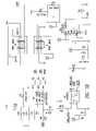
- FIGS. 7A-7Iare an electrical schematic diagram of the interrogation and detection system including a control circuit and antenna, according to one illustrated embodiment.
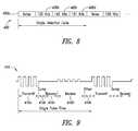
- FIG. 8is a timing diagram illustrating a method of frequency hopping, according to one illustrated embodiment.
- FIG. 9is a timing diagram illustrating pulsed timing, according to one illustrated embodiment.
- FIG. 10is a timing diagram showing activation of a pair of transistors of the control circuit in a push-pull configuration to drive the antenna, according to one illustrated embodiment.
- FIG. 11is a flow diagram of a method of operating an interrogation and control system, according to one illustrated embodiment.
- FIG. 12is a flow diagram of a method of operating an interrogation and control system with reduced false positives, according to one illustrated embodiment.
- FIG. 1shows a surgical environment 10 in which a medical provider 12 operates an interrogation and detection system 14 to ascertain the presence or absence of objects 16 in, or on, a patient 18 .
- the interrogation and detection system 14may include a controller 20 , and an antenna 22 coupled to the controller 20 by one or more communication paths, for example coaxial cable 24 .
- the antenna 22may take the form of a hand-held wand 22 a.
- the object 16may take a variety of forms, for example instruments, accessories and/or disposable objects useful in performing surgical procedures.
- the object 16may take the form of scalpels, scissors, forceps, hemostats, and/or clamps.
- the objects 16may take the form of surgical sponges, gauze and/or padding.
- the object 16is tagged, carrying, attached or otherwise coupled to a transponder 26 .
- Embodiments of the interrogation and detection system 14 disclosed hereinare particularly suited to operate with transponders 26 which are not accurately tuned to a chosen or selected resonant frequency. Consequently, the transponders 26 due not require high manufacturing tolerances or expensive materials, and thus may be inexpensive to manufacture.
- the medical provider 12may position the wand 22 a proximate the patient 18 in order to detect the presence or absence of the transponder 26 , and hence an object 16 .
- the medical provider 12may in some embodiments move the wand 22 a along and/or across the body of the patient 18 .
- the wand 22 amay be sized to fit at least partially in a body cavity 28 of the patient 18 .
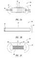
- FIG. 2Ashows a transponder 26 a according to one illustrated embodiment.
- the transponder 26 aincludes a miniature ferrite rod 30 with a conductive coil 32 wrapped about an exterior surface thereof to form an inductor (L), and a capacitor (C) 34 coupled to the conductive coil 32 to form a series LC circuit.
- the conductive coil 32may, for example, take the form of a spiral wound conductive wire with an electrically insulative sheath or sleeve.
- the transponder 26 amay include an encapsulation 36 that encapsulates the ferrite rod 30 , conductive coil 32 , and capacitor 34 .
- the encapsulant 36may be a bio-inert plastic, that protects the ferrite rod 30 , conductive coil 32 and/or capacitor 34 from pressure and/or from fluids, for example bodily fluids.
- the ferrite rod 30may include a passage 38 sized to receive a physical coupler, for example a bonding tie or string 40 .
- the bonding tie or string 40may take the form of an elastomeric x-ray opaque flexible elongated member, that may be used to attach the transponder 26 a to various types of objects 16 , for example surgical sponges.
- the transponder 26 amay have a length of about 8 millimeters and a diameter of about 2 millimeters. Employing such small dimensions ensures that the transponder 26 a does not impede deformation of objects 16 such as sponges.
- the transponder 26 amay include an optional diode (not shown), to protect against over-voltage occurrences caused by other electronic instruments.
- FIG. 2Bshows a transponder 26 b , according to another illustrated embodiment.
- the transponder 26 bincludes a single loop of conductive material 42 , for example a loop of conductive wire forming an inductor (L), coupled in series to a capacitor 44 (C) to form an LC series circuit.
- the loop of conductive material 42 and capacitor 44may be encapsulated in an elastomeric coating or sleeve 46 .
- the dimensions of the transponder 26 bmay be similar to the dimensions of the transponder 26 a . In some embodiments, the dimensions of the transponder 26 b are greater than the dimensions of the transponder 26 a .
- the transponder 26 bis highly flexible, and thus may provide its own thread-like or string-like attachment to various types of objects 16 .
- FIG. 2Cshows a transponder 26 c according to a further embodiment.
- the transponder 26 cincludes a dumbbell-shaped ferrite rod 48 having broad end portions 48 a , 48 b , and a narrow intermediate portion 48 c which is wrapped by a conductive coil 50 .
- the broad portions 48 a , 48 bcontain the conductive coils 50 .
- Such a designmay provide stronger and/or more reliable signal emission than transponders 26 a , 26 b fashioned with cylindrical ferrite rods.
- the transponder 26 cmay optionally include an encapsulant 52 . Further details regarding the transponder 26 c may be found in U.S. Provisional Patent Application No. 60/811,376 filed Jun. 6, 2006.
- the transponder 26 cmay be formed as a fusiform-shaped object, with truncated ends.
- the fusiform shapemay be advantageous over cylindrical shaped transponders 26 a , 26 b in reducing the likelihood of close parallel alignment of the transponders 26 a , 26 b , which may produce transponder-to-transponder interaction and interference.
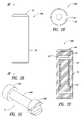
- FIGS. 2D-2Gshow a transponder 26 d according to yet a further embodiment.
- the transponder 26 dincludes a ferrite core 53 , inductor (L) 54 , and capacitor ⁇ 55 electrically coupled to the inductor 54 to form an LC series circuit.
- the transponder 26 dalso includes a capsule 56 with a cavity 57 open at one end to receive the ferrite core 53 , inductor 54 and capacitor 55 , as well as a lid 58 to close the open end of the capsule 56 .
- the drummay have a pair of larger diameter end portions 53 a , 53 b , with a smaller diameter intermediate portion 53 c therebetween.
- the inductor 54may take the form of magnet wire wrapped around the intermediate portion 53 c of the ferrite core 53 .
- the magnet wiremay, for example, have a dimension of approximately 41 American Wire Gauge (AWG), although some embodiments may employ wires or conductors of larger or small gauges.
- Suitable inductors 54may be commercially available from ELEKTISOLA under part no. PN-155 or from ROSEN under part no. 2UEW-F.
- the inductormay, for example, include approximately 432 turns, over approximately 6.5 layers, although some embodiments may include a greater or lesser number of turns and/or layers.
- the transponder 26 dmay include tape and/or epoxy enveloping the inductor 54 . Suitable tape may be commercially available from 3M under part nos. 1298, 1350-1 or PLEO 1P801, while suitable epoxy may be commercially available from LOCKTITE under part no. 3211.
- the capacitor 55may, for example, take the form of a ceramic capacitor.
- the capacitor 55may, for example, have a capacitance of 470PF, 100V, with a Quality factor of Q>2200@1 MHz.
- Suitable capacitors 55may be commercially available from SANJV DIELECTRIC under part no. 0805NPO471J101 or from FENG HUA under part no. 0805CG471J101NT.
- the capsule 56 and lid 58may, for example, be formed of a polypropylene. Suitable capsules 56 and lids 58 may be commercially available from WEITHE ELECTRON (HK) COMPANY, under part specification CASE 4.3 ⁇ 12.6. The combination of the capsule 56 and lid 58 may, for example, have a length of approximately 12.8 mm and a diameter of 4.4 mm. Circuit bonds may, for example, employ UNITED RESINS CORP. part no. 63001500 CIRCUIT BOND LV, while solder may take the form of a lead free 96.5% Ag/3% Sn/0.5Cu solder.
- the transponders 26may be attached to hemostats, scissors, certain forms of forceps, and the like.
- the transponders 26may be coupled to the object 16 by way of a clamp or holder.
- the transponders 26may be retained within a cavity of the holder.
- the holdermay be fashioned of a durable deformable material, such as surgical grade polymer, which may be deformed to clamp securely onto the finger or thumbhole of an instrument.
- the transponders 26may be attached to objects 16 by way of pouches fashioned of sheet material (e.g., surgical fabric) surrounding the transponder 26 .
- the transponder 26is retained within the pouch, and in some embodiments the pouch may be sewn or otherwise sealed. Sealing may be done with adhesive, hot glue, clamping, grommeting, or the like.
- FIGS. 3A and 3Bshow a wand 22 a , according to one illustrated embodiment.
- the wand 22 amay include a first housing structure 60 a and a second housing structure 60 b which mates to the first housing structure 60 a to form a housing 60 .
- the housing 60may include an annular portion 60 c and a handle portion 60 d extending from the annular portion.
- the handle portionmay be sized and dimensioned to be gripped by the hand of a medical provider 12 ( FIG. 1 ).
- the housing portions 60 a , 60 bmay be identical in shape to one another.
- the housing 60may define one or more cavities 62 sized and dimensioned to receive the antenna 22 .
- the antenna 22may, for example, take the form of an annulus or air-coil formed of coils of conductive material, for example wire. In one embodiment, the antenna 22 includes 10 turns evenly spaced between an inner diameter of about 11 inches and an outer diameter of about 14 inches. The antenna 22 acts as an inductor.
- the wand 22 amay include a coupling member 64 which may be positioned in the cavity in the handle portion 60 d to provide a connector to communicatively couple to an end of the coaxial cable 24 to the antenna 22 .
- the coupling member 64may take the form of a standard coaxial connector. Some embodiments may employ other types of communications pathways between the controller 20 and the antenna 22 , and thus may employ other types of coupling members or connectors.
- the wand 22 amay include one or more user interface devices, for example one or more visual indicators to provide visual indications to the medical provider 12 . Such may, for example, take the form of one or more light emitting diodes, which may produce one or more different colors. Such user interface devices may additionally, or alternatively include a speaker or other transducer, operable to produce a sound or other sensory indication, for example a tactile sensation. Such user interface devices may be configured to provide sensory feedback to the medical provider 12 indicative of an operating condition of the interrogation and detection system 14 . For example, such may indicate when the interrogation and detection system 14 is operating, when the presence of a transponder 26 has been identified, and/or when an error has occurred. Locating user interface devices on the wand 22 a may be advantageous since the medical provider 12 will typically focus their attention on the wand 22 a while scanning the patient 18 .
- FIG. 4shows the controller 20 according to one illustrated embodiment.
- the controller 20includes an input port 70 with an appropriate coupling member, for example a connector to allow an end of the coaxial cable 24 to be communicatively coupled to the controller 20 .
- an appropriate coupling memberfor example a connector to allow an end of the coaxial cable 24 to be communicatively coupled to the controller 20 .
- some embodimentsmay employ other communications pathways between the controller 20 and the antenna 22 , hence other types of coupling members or connectors may be employed.
- the controller 20may also include a power switch (not illustrated in FIG. 4 ), for example, positioned on a back or rear of the controller 20 .
- the controller 20may further include a power cord (not shown) to couple the controller 20 to a suitable power supply.
- the power supplymay, for example take the form of a standard wall outlet or any other power supply or source.
- the controller 20may further include one or more user interface devices for providing information to a user.
- the controller 20may include one or more visual indicators 134 , for instance one or more light emitting diodes (LEDs) and/or liquid crystal displays. Additionally, or alternatively, the controller 20 may include one or more speakers 130 or other transducers operable to produce sound or tactile sensations.
- LEDslight emitting diodes
- the controller 20may include one or more speakers 130 or other transducers operable to produce sound or tactile sensations.
- FIG. 5shows a control system 100 of the interrogation and detection system 14 , according to one illustrated embodiment.
- the control system 100includes a field programmable gate array (FPGA) board 102 , analog board 104 and display board 106 , communicatively coupled to one another.
- FPGAfield programmable gate array
- the FPGA boardincludes an FPGA 108 , configuration jumpers 110 , RS-232 drivers 112 , oscillator 114 , random access memory (RAM) 116 , flash memory 118 , and voltage monitoring (VMON) analog-to-digital converter (ADC) 120 .
- the FPGA 108may take the form of a Xilinx Spartan3 FPGA, which runs FPGA and application software. As explained below, on power up, the FPGA reads the configuration information and application software program from the flash memory 118 .
- the configuration jumpers 110are used to select the application software configuration.
- the RS-232 drivers 112are used to allow the application software to communicate using serial RS-232 data for factory test and diagnostics.
- the oscillator 114sets the clock frequency for the operation of the FPGA 108 .
- the oscillator 114may, for example, take the form of 40 MHz oscillator, although other frequencies are possible.
- the RAM 116is connected to the FPGA 108 and is available for use by the application software.
- the application softwareuses this memory space for storage of both the executable program and program data.
- the RAM 116may, for example, have a capacity of 1 MB.
- the flash memory 118contains both the FPGA configuration data and the binary application program. On power up the FPGA 108 reads the flash memory to configure the FPGA 108 and to copy the application program binary data from the flash memory 118 to the RAM 102 .
- the voltage monitor ADC 120is connected to the FPGA 108 and controlled by the application software to monitor a power supply and regulated voltage forms in controller electronics.
- the analog board 104includes transmit control circuits 122 , capacitor selection circuits 124 , wand detection circuit 126 , signal ADC 128 , audible beeper 130 and self-test signal 132 .
- the transmit control circuits 122 on the analog board 104are controlled by signals from the FPGA 108 to generate a transmit waveform. These signals are denominated as LO_FET_ON and HI_FET_ON, which control the transmit or drive transistors Q 1 , Q 2 ( FIG. 7A ) along with a signal denominated as DUMP_ON which controls a dump TRIAC ( FIG. 7A ).
- the capacitor selection circuits 124 on the analog board 104are controlled by the signals from the FPGA 108 to tune the drive circuit to match an inductance of the antenna 22 .
- the wand detection circuit 126detects when a wand 22 a is connected to the controller 20 .
- the output of the wand detection circuit 126drives a signal denominated as the LOOP_LEVEL_OUT signal, which is an input to the FPGA 108 .
- the signal ADC 128is used to sample the signals received at the antenna 22 a from the transponders 26 ( FIGS. 2A-2C ).
- the signal ADC 128may, for example, operate at a 1 MHz sample rate and may have 12-bits of resolution.
- the FPGA board 102generates the timing and control signals for the signal ADC 128 , which signal are denominated as ADC_CTRL, CS1, SCLK, SD0.
- the audible speaker or beeper 130can be controlled by the FPGA 108 to emit sounds to indicate various states, modes or operating conditions to the medical provider 12 ( FIG. 1 ).
- the FPGA 108can cause the generation of the self test signal 132 on the analog board 104 at the signal ADC 128 .
- Self-testingmay be performed at start up, and/or at other times, for example periodically or in response to the occurrence of certain conditions or exceptions.
- the display board 106includes user interface elements, for example a number of light emitting diodes (LEDs) 134 .
- the FPGA board 102can control the LEDs 134 on the display board 106 .
- the display board 106also includes a user selectable activation switch, denominated as front panel button 136 .
- the front panel button 136is connected to the display board 106 which allow the FPGA 108 to monitor when the front panel button 136 is activated (e.g., pressed).
- FIG. 6shows a software configuration 200 of the interrogation and detection system 14 , according to one illustrated embodiment.
- the softwaremay include application software 202 that is responsible for operating the electronics controller 20 ( FIGS. 1 and 4 ).
- the application software 202controls the timing for generating transmit pulses, processes sampled data to detect transponders 26 ( FIGS. 2A-2C ), and indicates status to the user with the display LED's 134 ( FIG. 5 ) on the display board 106 and/or via the audible speaker or beeper 130 on the analog board 104 .
- the application software 202is stored in the flash memory 118 ( FIG. 5 ) and transferred into the RAM 116 by a boot loader 204 .
- the boot loader 204is automatically loaded when the FPGA 108 is configured, and starts execution after a processor core 206 is reset.
- the boot loader 204is responsible for transferring the application software 202 from the flash memory 118 to the external RAM 116 .
- the processor platform 208is configured into the FPGA 108 ( FIG. 5 ) on power up from the configuration information stored in the flash memory 118 .
- the processor platform 208implements a custom microprocessor with a processor core 206 , peripherals 210 a - 210 n , and custom logic 212 .
- the processor core 206may take the form of a soft processor core supplied by XILINX under the name MICROBLAZE, that implements a 32-bit processor including memory cashes and a floating point unit.
- a soft core processoris one that is implemented by interconnected FPGA logic cells instead of by a traditional processor logic.
- the processor core 206is connected to the internal FPGA peripherals 210 a - 210 n using a 32-bit processor bus 211 called the On-Chip Peripheral Bus.
- the XILINX supplied peripherals for the MICROBLAZE processor core 206include external memory interfaces, timers, and general purpose I/O.
- the custom logic 212 to create the transmit signals, sample the ADC, and accumulate the transponder return signalsis designed as a peripheral to the processor core 206 .
- the custom logic 212is the part of the design of the FPGA 108 .
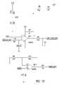
- FIGS. 7A-7Ishow a control circuit 300 according to one illustrated embodiment.
- the control circuit 300is used to drive the antenna 22 to excite or interrogate transponders 26 ( FIGS. 2A-2C ), and to detect and process signals received by the antenna 22 from the transponders 26 .
- the control circuit 300includes a transmitter circuit 302 formed by a pair of drive transistors (e.g., field effect transistors) Q 1 , Q 2 operated in a push-pull configuration between a high voltage rail (e.g., 24 V) and a low voltage rail (e.g., GND).
- the drive transistors Q 1 , Q 2are responsive to respective drive signals DRIVE_HI, DRIVE_LO, which are applied to the gates of the respective drive transistors Q 1 , Q 2 .
- the drive transistors Q 1 , Q 2are coupled to the antenna 22 by a non-switched capacitor C 8 and the coaxial cable 24 .
- the antenna 22 and capacitor C 8as well as capacitance provided by the coaxial cable 24 , form an LC circuit.
- the control circuit 300also includes a dynamic tuning circuit 304 .
- the dynamic tuning circuit 304selectively adjusts the capacitance of the LC circuit.
- the dynamic tuning circuit 304includes a number of switched capacitors C 33 -C 36 and relays U 9 , U 10 .
- the relays U 9 , U 10are operated to selectively couple the switched capacitors C 33 -C 36 in series with the non-switched capacitor C 8 , thereby adjusting the LC characteristics of the LC circuit, and allowing fine tuning of the LC circuit around center frequencies or center channels of a number of wide band frequency bands, as described in more detail below.
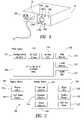
- FIG. 8illustrates a detection cycle 400 that employs frequency hopping, according to one illustrated embodiment.
- the application software 202( FIG. 6 ) implements the detection cycle 400 using transmission or interrogation in frequency bands centered around at least two center channels or frequencies.
- the application software 202sequences through a pattern of four different measurements each detection cycle 400 .
- the transmitteris turned OFF to take a measurement of the ambient noise.
- the next three measurements 400 b - 400 dare taken using different transmit frequency bands, for example around 139 KHz, 145 KHz and 151 KKHZ center channels or center frequencies of respective bands.
- FIG. 9illustrates pulse timing, according to one illustrated embodiment.
- the custom logic in the FPGA 108generates the timing and control signals for each pulse 410 .
- the logic of the FPGA 108drives the drive transistor control lines to generate the transmit signal.
- the FPGA logiccontrols the frequency of the transmit signal.
- the logic of the FPGA 108drives the gate of the dump TRIAC T 1 to quickly drain the transmit energy from the antenna 22 in order to allow detection of the response signal form the transponder 26 , if any.
- a recovery portion 410 c of the pulse 410allows receive filters and amplifiers to recover from the transmitted pulse before detecting the response signal from the transponder 26 , if any.
- the FPGA 108controls the signal ADC 128 to sample the response signal from the transponder 26 , if any.
- the signal ADC 128may, for example, sample at a 1 MHz sample rate with a 12-bit resolution.
- a dither portion 410 e of the pulse 410has a random variable length of time, and may, for example be generated by a pseudo-noise (PN) sequence generator. Adding a random length of time between pulses de-correlates the response signal received from the transponder 26 from constant frequency sources of interference, if any.
- PNpseudo-noise
- FIG. 10shows signal timing for driving the drive transistors Q 1 , Q 2 ( FIG. 7A ), according to one illustrated embodiment.
- the custom logic in the FPGA 108( FIG. 5 ) generates the signals 420 a , 420 b to drive the drive transistors Q 1 , Q 2 ( FIG. 7A ) during the transmit portion 410 a ( FIG. 9 ) of the pulse 410 .
- a transmit (TX) period valueis used by the logic of the FPGA 108 to set the transmit frequency.
- the low transistor (e.g., Low FET) Q 2turns ON at the beginning of the transmit period.
- the Low FET off valuecontrols when the low transistor (e.g., Low FET) Q 2 is turned OFF.
- the low transistor Q 2is turned OFF before the high transistor (e.g., High FET) Q 1 is turned ON to avoid a short circuit through the transistors Q 1 , Q 2 .
- the High FET on valuecontrols when the high transistor (e.g., High FET) Q 1 is turned ON.
- the High FET Off valuecontrols when the high transistor Q 1 is turned OFF.
- the high transistoris turned OFF before the low transistor Q 2 is turned ON to avoid a short circuit through the transistors Q 1 , Q 2 .
- the ADCconverts the signal received from the transponder 26 , if any, from analog to digital. Such conversion may, for example, be performed at a sampling rate of 1 MHz with a 12-bit data resolution. The sampled ADC data is then accumulated together, for example over 400 pulses, to compute the total summed response signal received from the transponder 26 , if any.
- the accumulated received signalis match filtered with both in-phase and quadrature reference signals to determine the signal magnitude.
- Each of the four receive signals from the sequences shownare processed with three match filter frequencies, for example as shown in Table 1 below.
- the maximum value for the nine matched filters with active transmitis compared with a fixed detection threshold. If the maximum value is greater than the detection threshold, then a response signal from a transponder 26 is considered as having been detected.
- FIG. 11shows a method 500 of operating the interrogation and detection system 14 according to one illustrated embodiment.
- the interrogation and detection system 14In response to detecting a disconnect of power, the interrogation and detection system 14 enters a Power OFF mode at 502 .
- the Power OFF mode 502may be entered when the controller 20 ( FIGS. 1 and 4 ) is unplugged or when the power switch on the controller 20 is turned OFF.
- the Power LED 134 a and other front panel LEDs 134will be turned OFF (non-emitting).
- the software 200is inoperative in the Power OFF mode 502 .
- the interrogation and detection system 14enters a Power-Up mode 504 .
- the Power UP mode 502may, for example, in response to the application of power to the controller 20 and turning ON the switch on the back of the controller.
- a Power LED 134 amay be turned ON or illuminated, and may remain ON or illuminated as long as the power is applied and the switch is in the ON state.
- the software 200will perform software initialization, built in tests, and an audio/visual test.
- the software 200progresses to a System Fault Mode 506 . If no faults are detected, the software 200 may turn a System Ready LED green, and enter a Wand Detection Mode 508 .
- the software 200may cause an indication of the detection of a system fault by blinking a System Ready LED 134 b yellow, and/or issuing a sequence of rapid beeps or other sounds.
- the corrective action for the System Fault Mode 506is to cycle power to reinitiate the Power Up mode 504 . Continued failure indicates a failed controller 20 .
- the software 200checks for a wand 22 a connected to the controller 20 .
- the Wand Detection Mode 508may be indicated by turning the System Ready LED 134 b green and turning the Wand Ready LED 134 c OFF. If no wand 22 a is detected, the software 200 remains in the Wand Detection Mode. If a wand 22 a is detected, the software 200 progresses to the Wand Initialization Mode 510 .
- the software 200may turn the Wand Ready LED 134 c yellow and check for the presence of a fuse in the wand 22 a . If a fuse is found, the software 200 may attempt to blow the fuse and verify that the fuse was correctly blown. After the fuse is blown the software 200 may verify that wand 22 a is operating within tolerances. The software 200 may indicate that the wand 22 a is ready by turning the Wand Ready LED 134 c green. The software 200 may also start a timer which will allow the wand 22 a to be disconnected and reconnected to the controller for a period to time (e.g., 5 hours) after the fuse is blown.
- a timerwhich will allow the wand 22 a to be disconnected and reconnected to the controller for a period to time (e.g., 5 hours) after the fuse is blown.
- the controller 20may determine the adjustments or fine tuning to be made about the center frequencies or channels during Wand Initialization Mode 510 .
- the controller 20may determine the particular frequency in each of the frequency bands that elicits the response with the highest voltage.
- the controllermay determine such be varying the capacitance of the LC circuit using the switched capacitors C 33 -C 36 during the Wand Initialization Mode 510 .
- the particular combination of switched capacitors C 33 -C 36 which achieved the response with the highest voltagemay then be automatically employed during the Scan Mode 514 (discussed below) to adjust or fine tune about the center frequency or channel in each broad band of transmission.
- Other approaches to determining the fine tuningmay be employed.
- the software 200If the software 200 does not successfully complete the Wand Initialization Mode 510 , the software 200 enters an Invalid Wand Mode 512 . If the software 200 successfully completes the Wand Initialization Mode 510 , the software 200 progresses to the Scan Mode 514 to automatically start scanning.
- the software 200may blink the Wand Ready LED 134 c yellow and issues a slow beep pattern.
- the Invalid Wand Modemay be entered in response to any of the following conditions:
- the corrective action for the Invalid Wand Mode 512is to remove the invalid wand 22 a and attach a new wand 22 a to the controller 20 that contains a fuse or to reconnect the wand 22 a while holding it in the air at least 2 feet away from large metallic objects.
- the software 200enters the Scan Mode 514 when the wand 22 a is ready and the operator presses a Start/Stop button.
- the software 200may issue a short three beep pattern via the speaker or beeper 130 when entering the Scan Mode 514 to identify the entry to the user.
- the software 200may continuously or periodically perform the following functions.
- the software 200may issue a short three beep pattern and return to the Wand Ready Mode 516 .
- the software 200may turn ON an amber DETECT LEDs 134 d and/or provide an audible alarm.
- the alarmmay, for example, beep a continuous solid tone as long as the transponder is detected, with a minimum of beep duration of, for instance 0.5 second.
- the software 200If the software 200 detects the wand 22 a is disconnected while in the Scan Mode 514 , the software 200 enter the Scan Fault Mode 520 .
- the software 200may issue a sequence of rapid beeps and blink ON and OFF the amber DETECT LEDs 134 d .
- the Scan Fault Mode 520can be cleared by pushing the Start/Stop button. The software 200 will automatically clear the scan fault mode 520 after 10 beeps.
- the software 200While in the Scan Mode 514 , if excess noise or loss of transmit signal is detected, the software 200 will progress to the Environment Error Mode 522 .
- the software 200may issue or produce an appropriate indication. For example, the software 200 may cause the production of a sequence of slow beeps and the blinking ON and OFF the green circle LEDs 134 e .
- the corrective action for the Environment Error Mode 522is to reposition the wand 22 a away from large metal objects or sources of electrical interference.
- the software 200will automatically stop the scan if the environment error condition lasts for more than a set time or number of beeps (e.g., 5 beeps).
- An alternative embodimentmay significantly reduce or eliminate the chance of false positives.
- Such an embodimentmay sample noise in a forward looking fashion in addition to a sample of noise in a backward looking fashion.
- the terms forward looking and backward lookingare relative, being used relative to a given sample. The forward looking samples occur later in time than the given sample and the backward looking samples occur earlier in time than the given sample.
- FIG. 12shows a method 1200 of operating an interrogation and control system with reduced false positives, according to one illustrated embodiment.
- a sampleis taken at a first time sufficiently spaced by the delay in time 1202 from any prior interrogation signals such that the sample represents a “backward looking” noise sample.
- an interrogation signalis transmitted.
- a sampleis taken at a second time sufficiently close to the interrogation signal such that the sample represents a signal sample, which may contain a return signal, if any, returned in response to the interrogation signal.
- a “forward looking” sampleis taken at third time, sufficiently spaced in time from the interrogation signal such that the sample represents a “forward looking” noise sample.
- the greater of the backward looking and forward looking noise samplesare determined.
- the signal sampleis compared with the determined greater one of the backward looking and forward looking noise samples to determine whether a response has been received from a transponder 26 . An appropriate alert may be provided if a response has been received.
- the method 1200may advantageously address issues related to the fluctuation of the noise floor which may, for example, result from movement of the wand 22 a .
- the duration of the signal samplemay be longer than a duration of the noise samples, which will make the operation less sensitive to noise which, as previously noted, drops off as the square root of the sample.
- signal bearing mediainclude, but are not limited to, the following: recordable type media such as floppy disks, hard disk drives, CD ROMs, digital tape, and computer memory; and transmission type media such as digital and analog communication links using TDM or IP based communication links (e.g., packet links).
Landscapes
- Health & Medical Sciences (AREA)
- Life Sciences & Earth Sciences (AREA)
- Engineering & Computer Science (AREA)
- Heart & Thoracic Surgery (AREA)
- Molecular Biology (AREA)
- Biophysics (AREA)
- Pathology (AREA)
- Biomedical Technology (AREA)
- Human Computer Interaction (AREA)
- Medical Informatics (AREA)
- Physics & Mathematics (AREA)
- Surgery (AREA)
- Animal Behavior & Ethology (AREA)
- General Health & Medical Sciences (AREA)
- Public Health (AREA)
- Veterinary Medicine (AREA)
- Radar Systems Or Details Thereof (AREA)
- Near-Field Transmission Systems (AREA)
Abstract
Description
| TABLE 1 | ||||
| Match Freq | 1 | |||
| 139 KHz | 145 KHz | 151 KHz | ||
| 139 KHz | 136 KHz | 139 KHz | 142 KHz | |
| 145 KHz | 142 KHz | 145 KHz | 148 KHz | |
| 151 KHz | 148 KHz | 151 KHz | 154 KHz | |
- The
wand 22aconnected to thecontroller 20 is out of tolerance. - The
controller 20 is unable to blow the fuse in thewand 22a. - The
wand 22adoes not have a fuse and more than the set time period has past (e.g., 5 hours) since a fuse was blown. - The
wand 22adoes not have a fuse and thecontroller 20 has been restarted. - The
wand 22ahas been connected to the controller for more than the set time period (e.g., 5 hours). - The
wand 22ais detuned due to close proximity to metal.
- The
- Look for response signals from
transponders 26 - Monitor the noise level
- Insure the
wand 22ais connected and operating correctly - Blink the LED's in a circular pattern
- Look for response signals from
Claims (35)
Priority Applications (1)
| Application Number | Priority Date | Filing Date | Title |
|---|---|---|---|
| US12/038,593US8710957B2 (en) | 2007-02-28 | 2008-02-27 | Method, apparatus and article for detection of transponder tagged objects, for example during surgery |
Applications Claiming Priority (2)
| Application Number | Priority Date | Filing Date | Title |
|---|---|---|---|
| US89220807P | 2007-02-28 | 2007-02-28 | |
| US12/038,593US8710957B2 (en) | 2007-02-28 | 2008-02-27 | Method, apparatus and article for detection of transponder tagged objects, for example during surgery |
Publications (2)
| Publication Number | Publication Date |
|---|---|
| US20080204245A1 US20080204245A1 (en) | 2008-08-28 |
| US8710957B2true US8710957B2 (en) | 2014-04-29 |
Family
ID=39715253
Family Applications (1)
| Application Number | Title | Priority Date | Filing Date |
|---|---|---|---|
| US12/038,593Active2031-02-22US8710957B2 (en) | 2007-02-28 | 2008-02-27 | Method, apparatus and article for detection of transponder tagged objects, for example during surgery |
Country Status (3)
| Country | Link |
|---|---|
| US (1) | US8710957B2 (en) |
| EP (1) | EP2119025A1 (en) |
| WO (1) | WO2008106552A1 (en) |
Cited By (24)
| Publication number | Priority date | Publication date | Assignee | Title |
|---|---|---|---|---|
| US20160166173A9 (en)* | 2012-11-16 | 2016-06-16 | Integrated Medical Technologies, Inc. | Device For The Detection Of Metallic Surgical Articles And Harmonic And RFID Tagging Markers |
| EP3047815A1 (en) | 2015-01-21 | 2016-07-27 | Covidien LP | Wirelessly detectable objects for use in medical procedures and methods of making same |
| EP3047816A1 (en) | 2015-01-21 | 2016-07-27 | Covidien LP | Wirelessly detectable objects for use in medical procedures and methods of making same |
| US9690963B2 (en) | 2015-03-02 | 2017-06-27 | Covidien Lp | Hand-held dual spherical antenna system |
| US9814540B2 (en) | 2014-03-31 | 2017-11-14 | Covidien Lp | Method, apparatus and article for detection of transponder tagged objects, for example during surgery |
| WO2018013413A1 (en) | 2016-07-11 | 2018-01-18 | Covidien Lp | Method and apparatus to account for transponder tagged objects used during clinical procedures employing a shielded receptacle with antenna |
| US10154885B1 (en) | 2017-05-26 | 2018-12-18 | Medline Industries, Inc. | Systems, apparatus and methods for continuously tracking medical items throughout a procedure |
| US10193209B2 (en) | 2015-04-06 | 2019-01-29 | Covidien Lp | Mat based antenna and heater system, for use during medical procedures |
| US10285775B2 (en) | 2015-02-26 | 2019-05-14 | Covidien Lp | Apparatuses to physically couple transponder to objects, such as surgical objects, and methods of using same |
| US10339269B2 (en) | 2014-03-31 | 2019-07-02 | Covidien Lp | Hand-held spherical antenna system to detect transponder tagged objects, for example during surgery |
| EP3545882A1 (en) | 2018-03-27 | 2019-10-02 | Covidien LP | Apparatus to account for transponder tagged objects used during clinical procedures, employing a trocar |
| EP3581127A1 (en) | 2018-03-27 | 2019-12-18 | Covidien LP | Apparatus to account for transponder tagged objects used during clinical procedures, employing a trocar |
| EP3590461A1 (en) | 2018-07-02 | 2020-01-08 | Covidien LP | Method and apparatus related to fabricated wireless transponder devices to be used in medical procedures |
| US10595958B2 (en) | 2008-10-28 | 2020-03-24 | Covidien Lp | Wirelessly detectable objects for use in medical procedures and methods of making same |
| EP3653118A1 (en) | 2018-10-04 | 2020-05-20 | Covidien LP | Wirelessly detectable object that emits a variable-frequency response signal, and method and system for detecting and locating same |
| US10660726B2 (en) | 2015-01-21 | 2020-05-26 | Covidien Lp | Sterilizable wirelessly detectable objects for use in medical procedures and methods of making same |
| US10709521B2 (en) | 2016-07-11 | 2020-07-14 | Covidien Lp | Method and apparatus to account for transponder tagged objects used during clinical procedures, employing a shielded receptacle |
| US10722323B2 (en) | 2009-11-23 | 2020-07-28 | Covidien Lp | Method and apparatus to account for transponder tagged objects used during medical procedures |
| US10835348B2 (en) | 2016-07-11 | 2020-11-17 | Covidien Lp | Method and apparatus to account for transponder tagged objects used during clinical procedures, for example including count in and/or count out and presence detection |
| US10874560B2 (en) | 2015-01-21 | 2020-12-29 | Covidien Lp | Detectable sponges for use in medical procedures and methods of making, packaging, and accounting for same |
| US11065080B2 (en) | 2016-07-11 | 2021-07-20 | Covidien Lp | Method and apparatus to account for transponder tagged objects used during clinical procedures, employing a trocar |
| US20220185560A1 (en)* | 2020-12-16 | 2022-06-16 | Haldor Advanced Technologies Ltd. | Fluorinated shrink wrap for surgical item identification tags |
| US11617625B2 (en) | 2019-03-12 | 2023-04-04 | Medline Industries, Lp | Systems, apparatus and methods for properly locating items |
| US12059276B2 (en) | 2019-08-21 | 2024-08-13 | Medline Industries, Lp | Systems, apparatus and methods for automatically counting medical objects, estimating blood loss and/or communicating between medical equipment |
Families Citing this family (26)
| Publication number | Priority date | Publication date | Assignee | Title |
|---|---|---|---|---|
| US7696877B2 (en) | 2007-05-01 | 2010-04-13 | Rf Surgical Systems, Inc. | Method, apparatus and article for detection of transponder tagged objects, for example during surgery |
| WO2009151946A2 (en) | 2008-05-27 | 2009-12-17 | Rf Surgical Systems, Inc. | Multi-modal transponder and method and apparatus to detect same |
| WO2009154987A2 (en)* | 2008-05-28 | 2009-12-23 | Rf Surgical Systems, Inc. | Method, apparatus and article for detection of transponder tagged objects, for example during surgery |
| US8354931B2 (en)* | 2008-08-06 | 2013-01-15 | Rf Surgical Systems, Inc. | Transponder device to mark implements, such as surgical implements, and method of manufacturing and using same |
| US8264342B2 (en) | 2008-10-28 | 2012-09-11 | RF Surgical Systems, Inc | Method and apparatus to detect transponder tagged objects, for example during medical procedures |
| EP2182383A1 (en)* | 2008-10-30 | 2010-05-05 | Nederlandse Organisatie voor toegepast-natuurwetenschappelijk Onderzoek TNO | A measurement agent, a tag, a method for measuring, a method for serving measuring and a computer program product |
| US9792408B2 (en) | 2009-07-02 | 2017-10-17 | Covidien Lp | Method and apparatus to detect transponder tagged objects and to communicate with medical telemetry devices, for example during medical procedures |
| US8826473B2 (en) | 2011-07-19 | 2014-09-09 | Hill-Rom Services, Inc. | Moisture detection system |
| US20140276504A1 (en)* | 2013-03-13 | 2014-09-18 | Hill-Rom Services, Inc. | Methods and apparatuses for the detection of incontinence or other moisture, methods of fluid analysis, and multifunctional sensor systems |
| US8692140B1 (en) | 2013-03-15 | 2014-04-08 | Surgitrac Corporation | Surgical object and fluid monitoring system having highly sensitive and reliable detection of objects being placed in a container |
| US8963025B2 (en) | 2013-03-15 | 2015-02-24 | Surgitrac Corporation | Surgical object and fluid monitoring system having highly sensitive and reliable detection of objects being placed in a container |
| US8704178B1 (en) | 2013-03-15 | 2014-04-22 | Surgitrac Corporation | Container for surgical object and fluid monitoring system |
| US9347817B2 (en) | 2013-03-15 | 2016-05-24 | Surgitrac Corporation | Surgical object and comprehensive fluid monitoring system having capability of mobile monitoring and having highly sensitive and reliable detection of objects being placed in a container |
| WO2015061671A1 (en) | 2013-10-24 | 2015-04-30 | Rf Surgical Systems, Inc. | Surgical sponge distribution systems and methods |
| USD775331S1 (en) | 2015-03-02 | 2016-12-27 | Covidien Lp | Hand-held antenna system |
| US10653567B2 (en) | 2015-11-16 | 2020-05-19 | Hill-Rom Services, Inc. | Incontinence detection pad validation apparatus and method |
| US11707387B2 (en) | 2015-11-16 | 2023-07-25 | Hill-Rom Services, Inc. | Incontinence detection method |
| EP3376946A1 (en) | 2015-11-16 | 2018-09-26 | Hill-Rom Services, Inc. | Incontinence detection systems for hospital beds |
| US10115291B2 (en) | 2016-04-26 | 2018-10-30 | Hill-Rom Services, Inc. | Location-based incontinence detection |
| US20180146906A1 (en) | 2016-11-29 | 2018-05-31 | Hill-Rom Services, Inc. | System and method for determining incontinence device replacement interval |
| US10716715B2 (en) | 2017-08-29 | 2020-07-21 | Hill-Rom Services, Inc. | RFID tag inlay for incontinence detection pad |
| US10945892B2 (en) | 2018-05-31 | 2021-03-16 | Hill-Rom Services, Inc. | Incontinence detection system and detectors |
| US11950987B2 (en) | 2019-05-21 | 2024-04-09 | Hill-Rom Services, Inc. | Manufacturing method for incontinence detection pads having wireless communication capability |
| US12048613B2 (en) | 2019-09-30 | 2024-07-30 | Hill-Rom Services, Inc. | Incontinence detection system |
| US11712186B2 (en) | 2019-09-30 | 2023-08-01 | Hill-Rom Services, Inc. | Incontinence detection with real time location information |
| US11620464B2 (en) | 2020-03-31 | 2023-04-04 | Covidien Lp | In-vivo introducible antenna for detection of RF tags |
Citations (226)
| Publication number | Priority date | Publication date | Assignee | Title |
|---|---|---|---|---|
| US2740405A (en) | 1948-08-04 | 1956-04-03 | Howard C Riordan | Surgical sponge with radioactive tracer |
| US3031864A (en) | 1959-06-30 | 1962-05-01 | Freundich Clarence | Earring |
| US3422816A (en) | 1964-12-09 | 1969-01-21 | Johnson & Johnson | Surgical dressing |
| US3587583A (en) | 1969-07-07 | 1971-06-28 | Irving Melbourne Greenberg | Surgical sponge with magnetized means |
| US4034297A (en) | 1976-01-13 | 1977-07-05 | General Electric Company | Circuit for disabling a radio transmitter which is continuously operated longer than a predetermined time |
| US4114601A (en) | 1976-08-09 | 1978-09-19 | Micro Tec Instrumentation, Inc. | Medical and surgical implement detection system |
| US4193405A (en) | 1976-08-09 | 1980-03-18 | Micro Tec Instrumentation Inc. | Detectable medical and surgical implements |
| US4422548A (en) | 1982-01-18 | 1983-12-27 | Ritmed Limited | Surgical sponge counter and blood loss determination system |
| USD272943S (en) | 1981-06-22 | 1984-03-06 | Stone Robert D | Electrode for biomedical signals |
| US4477256A (en) | 1982-02-11 | 1984-10-16 | Win Hirsch | Surgical sponge |
| US4540398A (en) | 1983-03-29 | 1985-09-10 | Johnson & Johnson Products, Inc. | Knitted surgical swabs |
| US4626251A (en) | 1985-02-22 | 1986-12-02 | Albert Shen | Surgical sponge |
| US4636208A (en) | 1984-10-05 | 1987-01-13 | Ewald Rath | Surgical sponge |
| US4639253A (en) | 1984-04-30 | 1987-01-27 | Johnson & Johnson Products, Inc. | Nonwoven surgical sponge with X-ray detectable element |
| US4645499A (en) | 1983-08-22 | 1987-02-24 | The Kendall Company | Surgical sponge |
| US4658818A (en) | 1985-04-12 | 1987-04-21 | Miller Jr George E | Apparatus for tagging and detecting surgical implements |
| US4681111A (en) | 1985-04-05 | 1987-07-21 | Siemens-Pacesetter, Inc. | Analog and digital telemetry system for an implantable device |
| US4704109A (en) | 1983-08-22 | 1987-11-03 | The Kendall Company | Surgical sponge |
| US4718897A (en) | 1985-09-18 | 1988-01-12 | Chicopee | Nonwoven surgical sponge with x-ray detectable element |
| US4893118A (en) | 1986-11-25 | 1990-01-09 | Societe Fontaine | Device for identification by proximity |
| US4917694A (en) | 1982-05-19 | 1990-04-17 | The Kendall Company | Surgical sponge |
| US4935019A (en) | 1986-12-22 | 1990-06-19 | Johnson & Johnson Medical, Inc. | Radiopaque polymeric composition |
| US4938901A (en) | 1986-12-02 | 1990-07-03 | Firma Carl Freudenberg | Process of making a surgical sponge containing an x-ray contrast agent |
| US4992675A (en) | 1989-03-30 | 1991-02-12 | Motorola, Inc. | Adaptive threshold control circuit |
| US5031642A (en) | 1989-04-06 | 1991-07-16 | Nosek Bettie L | Integrator - collector for surgical/medical procedures |
| US5041103A (en) | 1983-08-22 | 1991-08-20 | The Kendall Company | Surgical sponge and method of making |
| US5045080A (en) | 1986-12-22 | 1991-09-03 | Johnson & Johnson Medical, Inc. | Surgical fabric with printed X-ray marker |
| US5049219A (en) | 1990-03-06 | 1991-09-17 | Deroyal Industries, Inc. | Method and apparatus for manufacturing surgical sponges |
| US5057095A (en) | 1989-11-16 | 1991-10-15 | Fabian Carl E | Surgical implement detector utilizing a resonant marker |
| US5105829A (en) | 1989-11-16 | 1992-04-21 | Fabian Carl E | Surgical implement detector utilizing capacitive coupling |
| US5107862A (en) | 1991-05-06 | 1992-04-28 | Fabian Carl E | Surgical implement detector utilizing a powered marker |
| US5112325A (en) | 1989-02-17 | 1992-05-12 | Deroyal Industries, Inc. | Surgical sponge with plurality of radiopaque monofilaments |
| USD330872S (en) | 1990-09-19 | 1992-11-10 | Mary Jane S. Ball | Earring |
| US5181021A (en) | 1991-01-14 | 1993-01-19 | Eastman Kodak Co. | Responder target for theft detection apparatus |
| US5188126A (en) | 1989-11-16 | 1993-02-23 | Fabian Carl E | Surgical implement detector utilizing capacitive coupling |
| US5190059A (en) | 1989-11-16 | 1993-03-02 | Fabian Carl E | Surgical implement detector utilizing a powered marker |
| US5224593A (en) | 1992-01-13 | 1993-07-06 | Allergan, Inc. | Lens shipper/lens case |
| US5235326A (en) | 1991-08-15 | 1993-08-10 | Avid Corporation | Multi-mode identification system |
| US5258742A (en) | 1991-03-14 | 1993-11-02 | Jose Soldevila Domingo | Gauze counter apparatus for surgical use |
| US5329944A (en) | 1989-11-16 | 1994-07-19 | Fabian Carl E | Surgical implement detector utilizing an acoustic marker |
| US5353011A (en) | 1993-01-04 | 1994-10-04 | Checkpoint Systems, Inc. | Electronic article security system with digital signal processing and increased detection range |
| USD353343S (en) | 1992-03-17 | 1994-12-13 | Indala Corporation | Identification transponder tag for fabric-type articles |
| USD354927S (en) | 1992-01-07 | 1995-01-31 | Diamant Applications S.A. | Diamond earring |
| USD359705S (en) | 1994-02-01 | 1995-06-27 | Ball M J Suzie | Condom earring |
| US5446447A (en) | 1994-02-16 | 1995-08-29 | Motorola, Inc. | RF tagging system including RF tags with variable frequency resonant circuits |
| US5450622A (en) | 1991-07-23 | 1995-09-12 | Ericsson Inc. | Method and apparatus for providing a very fast acting noise squelch control system for an RF radio receiver |
| US5456718A (en) | 1992-11-17 | 1995-10-10 | Szymaitis; Dennis W. | Apparatus for detecting surgical objects within the human body |
| US5482036A (en) | 1991-03-07 | 1996-01-09 | Masimo Corporation | Signal processing apparatus and method |
| US5575781A (en) | 1995-10-05 | 1996-11-19 | Deroyal Industries, Inc. | Absorbent article useful in medical applications |
| US5629498A (en) | 1995-01-18 | 1997-05-13 | Richard A. Pollock | Intraoperative tracking devices and processes |
| US5650596A (en) | 1994-08-05 | 1997-07-22 | Surgical Resources, L.L.C. | Automatic surgical sponge counter and blood loss determination system |
| US5664582A (en) | 1992-11-17 | 1997-09-09 | Szymaitis; Dennis W. | Method for detecting, distinguishing and counting objects |
| US5725517A (en) | 1995-10-05 | 1998-03-10 | Deroyal Industries, Inc. | Absorbent woven article including radiopaque element woven therein and anchored at the ends thereof |
| US5792128A (en) | 1995-10-05 | 1998-08-11 | Deroyal Industries, Inc. | Absorbent article having a radiopaque element embedded in a side edge thereof and method for making same |
| US5923001A (en) | 1994-08-05 | 1999-07-13 | Surgical Resources, L.L.C. | Automatic surgical sponge counter and blood loss determination system |
| USD412135S (en) | 1998-09-24 | 1999-07-20 | Toshihiko Saito | Combined double gems and coil spring for fingers |
| US5928151A (en) | 1997-08-22 | 1999-07-27 | Acuson Corporation | Ultrasonic system and method for harmonic imaging in three dimensions |
| US5931824A (en) | 1996-09-04 | 1999-08-03 | Stewart; William W. | Identification and accountability system for surgical sponges |
| US5963132A (en) | 1996-10-11 | 1999-10-05 | Avid Indentification Systems, Inc. | Encapsulated implantable transponder |
| US5969613A (en) | 1997-08-11 | 1999-10-19 | Alpha Enterprises, Inc. | Electronic article surveillance security device |
| USD418773S (en) | 1998-07-10 | 2000-01-11 | Toshihiko Saito | Combined gem and coil spring support for toes |
| US6026818A (en) | 1998-03-02 | 2000-02-22 | Blair Port Ltd. | Tag and detection device |
| USD423673S (en) | 1998-09-01 | 2000-04-25 | Medicotest A/S | Electrode for medical use |
| US6075797A (en) | 1997-10-17 | 2000-06-13 | 3Com Corporation | Method and system for detecting mobility of a wireless-capable modem to minimize data transfer rate renegotiations |
| US6093869A (en) | 1998-06-29 | 2000-07-25 | The Procter & Gamble Company | Disposable article having a responsive system including a feedback control loop |
| US6172608B1 (en) | 1996-06-19 | 2001-01-09 | Integrated Silicon Design Pty. Ltd. | Enhanced range transponder system |
| US6201469B1 (en)* | 1999-02-12 | 2001-03-13 | Sensormatic Electronics Corporation | Wireless synchronization of pulsed magnetic EAS systems |
| US6211666B1 (en) | 1996-02-27 | 2001-04-03 | Biosense, Inc. | Object location system and method using field actuation sequences having different field strengths |
| US6215437B1 (en) | 1998-10-13 | 2001-04-10 | Texas Instruments Incorporated | Procedure for reading the data stored in a transponder and a transponder system for the execution of the procedure |
| US6223137B1 (en) | 1999-03-25 | 2001-04-24 | The University Of Tennessee Research Corporation | Method for marking, tracking, and managing hospital instruments |
| US6232878B1 (en) | 1999-05-20 | 2001-05-15 | Checkpoint Systems, Inc. | Resonant circuit detection, measurement and deactivation system employing a numerically controlled oscillator |
| US6270460B1 (en) | 1999-06-24 | 2001-08-07 | Acuson Corporation | Apparatus and method to limit the life span of a diagnostic medical ultrasound probe |
| US6276033B1 (en) | 1997-05-05 | 2001-08-21 | Lenscrafters, Inc. | Security tag housing |
| US20010030610A1 (en) | 2000-02-08 | 2001-10-18 | Rochelle James M. | Wireless boundary proximity determining and animal containment system and method |
| US6317027B1 (en) | 1999-01-12 | 2001-11-13 | Randy Watkins | Auto-tunning scanning proximity reader |
| US20020011932A1 (en)* | 1998-06-02 | 2002-01-31 | Rf Code, Inc. | Object identification system with adaptive transceivers and methods of operation |
| US6349234B2 (en) | 1998-06-12 | 2002-02-19 | Intermedics Inc. | Implantable device with optical telemetry |
| US6353406B1 (en)* | 1996-10-17 | 2002-03-05 | R.F. Technologies, Inc. | Dual mode tracking system |
| US20020032435A1 (en) | 2000-06-20 | 2002-03-14 | Levin Bruce H. | Tracking surgical implements with integrated circuits |
| US6366206B1 (en) | 1999-06-02 | 2002-04-02 | Ball Semiconductor, Inc. | Method and apparatus for attaching tags to medical and non-medical devices |
| WO2002033917A1 (en) | 2000-10-20 | 2002-04-25 | Siemens Aktiengesellschaft | Method for transmitting digital data, particularly over an electric network, as well as associated units and an associated program |
| USD456907S1 (en) | 2001-07-17 | 2002-05-07 | Robert Michael Sanfilippo | Medical electrode |
| US6384296B1 (en) | 1998-06-29 | 2002-05-07 | The Procter & Gamble Company | Disposable article having a responsive system including an electrical actuator |
| US6401722B1 (en) | 1998-06-12 | 2002-06-11 | Calypso Medical Technologies, Inc. | Method for stabilizing and removing tissue |
| US20020070863A1 (en) | 1999-03-16 | 2002-06-13 | Brooking Timothy John | Tagging system and method |
| US6441741B1 (en) | 1999-05-17 | 2002-08-27 | Avid Identification Systems, Inc. | Overmolded transponder |
| US20020143320A1 (en) | 2001-03-30 | 2002-10-03 | Levin Bruce H. | Tracking medical products with integrated circuits |
| US20020165587A1 (en) | 1999-10-01 | 2002-11-07 | Cardiac Pacemakers, Inc. | Method and apparatus for adjusting the sensing threshold of a cardiac rhythm management device |
| US20020188259A1 (en) | 2001-05-21 | 2002-12-12 | Scott Laboratories, Inc. | Smart supplies, components and capital equipment |
| US20030004411A1 (en) | 1999-03-11 | 2003-01-02 | Assaf Govari | Invasive medical device with position sensing and display |
| USD471281S1 (en) | 2000-07-10 | 2003-03-04 | Cardiodynamics International Corporation | Electrode for use on a living subject |
| US20030052788A1 (en) | 2001-09-19 | 2003-03-20 | Kevin Kwong-Tai Chung | Medical assistance and tracking system and method employing smart tags |
| US6557752B1 (en) | 1996-06-12 | 2003-05-06 | Q-International, Inc. | Smart card for recording identification, and operational, service and maintenance transactions |
| US6566997B1 (en)* | 1999-12-03 | 2003-05-20 | Hid Corporation | Interference control method for RFID systems |
| US20030105394A1 (en) | 2001-12-03 | 2003-06-05 | Fabian Carl R. | Portable surgical implement detector |
| US6588661B2 (en) | 2001-03-23 | 2003-07-08 | Em Microelectronic-Marin Sa | System and method for wireless communication between several transceivers, arranged respectively in several delimited spaces, and portable electronic units |
| US6632216B2 (en) | 1999-12-21 | 2003-10-14 | Phaeton Research Ltd. | Ingestible device |
| US6633226B1 (en) | 1997-08-18 | 2003-10-14 | X-Cyte, Inc. | Frequency hopping spread spectrum passive acoustic wave identification device |
| US6641039B2 (en) | 2002-03-21 | 2003-11-04 | Alcon, Inc. | Surgical procedure identification system |
| US6650240B2 (en) | 2002-01-18 | 2003-11-18 | Techtalion Limited | Apparatus and method for tracking articles during travel |
| US6654629B2 (en) | 2002-01-23 | 2003-11-25 | Valentino Montegrande | Implantable biomarker and method of use |
| US20040008123A1 (en) | 2002-07-15 | 2004-01-15 | Battelle Memorial Institute | System and method for tracking medical devices |
| US6696954B2 (en) | 2000-10-16 | 2004-02-24 | Amerasia International Technology, Inc. | Antenna array for smart RFID tags |
| US6722783B2 (en) | 2001-12-31 | 2004-04-20 | Ronnie W. Jackson, Sr. | X-ray chair |
| US6734795B2 (en) | 2000-08-14 | 2004-05-11 | William Raymond Price | Location of lost dentures using RF transponders |
| US6744378B1 (en) | 2000-09-01 | 2004-06-01 | Traffic Monitoring Services, Inc. | Roadway sensor with improved insulated signal carrying wires |
| US6753783B2 (en) | 2001-03-30 | 2004-06-22 | Augmentech, Inc. | Patient positioning monitoring apparatus and method of use thereof |
| US20040129279A1 (en) | 2002-11-26 | 2004-07-08 | Fabian Carl E. | Miniature magnetomechanical tag for detecting surgical sponges and implements |
| US20040137844A1 (en) | 2002-09-02 | 2004-07-15 | Em Microelectronic - Marin Sa | Adjustment of the detection, transmission and/or reception parameters of an RFID reader as a function of ambient electromagnetic noise |
| US20040138554A1 (en) | 2002-12-30 | 2004-07-15 | Dimmer Steven C. | Implantable marker with a leadless signal transmitter compatible for use in magnetic resonance devices |
| US6777623B2 (en) | 2002-04-17 | 2004-08-17 | M. Daniel Ballard | System and method of tracking surgical sponges |
| USD495055S1 (en) | 2003-09-10 | 2004-08-24 | Koninklijke Philips Electronics N.V. | Electrode for use on a living subject |
| US6786405B2 (en) | 2002-02-28 | 2004-09-07 | Curt Wiedenhoefer | Tissue and implant product supply system and method |
| WO2004086997A1 (en) | 2003-03-27 | 2004-10-14 | Blair William A | Apparatus and method for detecting objects using tags and wideband detection device |
| US6812824B1 (en) | 1996-10-17 | 2004-11-02 | Rf Technologies, Inc. | Method and apparatus combining a tracking system and a wireless communication system |
| US6812842B2 (en) | 2001-12-20 | 2004-11-02 | Calypso Medical Technologies, Inc. | System for excitation of a leadless miniature marker |
| US6822570B2 (en) | 2001-12-20 | 2004-11-23 | Calypso Medical Technologies, Inc. | System for spatially adjustable excitation of leadless miniature marker |
| US20040254420A1 (en) | 2003-06-16 | 2004-12-16 | Brian Ward | Macular and scleral support surgical device for ocular restraint in progressive high myopia |
| US6838990B2 (en) | 2001-12-20 | 2005-01-04 | Calypso Medical Technologies, Inc. | System for excitation leadless miniature marker |
| USD502419S1 (en) | 2003-04-04 | 2005-03-01 | Alpha Security Products, Inc. | Theft deterrent device |
| US20050049564A1 (en) | 2003-08-28 | 2005-03-03 | Fabian Carl E. | Attachment of electronic tags to surgical sponges and implements |
| US6909366B1 (en) | 1998-03-04 | 2005-06-21 | Trolley Scan (Proprietary) Limited | Multi-dimensional electronic identification of articles |
| US20050154293A1 (en) | 2003-12-24 | 2005-07-14 | Margo Gisselberg | Implantable marker with wireless signal transmitter |
| US20050212673A1 (en) | 2004-03-24 | 2005-09-29 | Forster Ian J | System and method for selectively reading RFID devices |
| US20050247794A1 (en) | 2004-03-26 | 2005-11-10 | Jones Robert L | Identification document having intrusion resistance |
| US20050249036A1 (en) | 2002-09-20 | 2005-11-10 | Qinetiq Limited | Underwater location apparatus |
| US20050267550A1 (en) | 2004-05-28 | 2005-12-01 | Medtronic Minimed, Inc. | System and method for medical communication device and communication protocol for same |
| US6977504B2 (en) | 2003-12-31 | 2005-12-20 | Calypso Medical Technologies, Inc. | Receiver used in marker localization sensing system using coherent detection |
| EP1612554A1 (en) | 2004-06-29 | 2006-01-04 | Lifescan, Inc. | A method of preventing reuse of a test strip |
| US6998541B2 (en) | 1994-08-05 | 2006-02-14 | Clearcount Medical Solutions, Inc. | Automatic surgical sponge counter and blood loss determination system |
| US20060055537A1 (en) | 2004-09-15 | 2006-03-16 | Radarfind Corporation | Methods, identification tags and computer program products for automated location and monitoring of mobile devices |
| US7019650B2 (en) | 2003-03-03 | 2006-03-28 | Caducys, L.L.C. | Interrogator and interrogation system employing the same |
| US7026924B2 (en) | 2001-03-08 | 2006-04-11 | Em Microelectronic - Marin Sa | System for detecting individuals or objects passing through an entrance-exit of a defined space |
| US7026927B2 (en) | 2003-12-31 | 2006-04-11 | Calypso Medical Technologies, Inc. | Receiver used in marker localization sensing system and having dithering in excitation pulses |
| US20060084934A1 (en) | 2004-10-18 | 2006-04-20 | Milton Frank | Transponder assembly and method for making same |
| US20060106368A1 (en) | 2004-11-15 | 2006-05-18 | Smart Technologies, Llc | Smart Surgical Device Operating System With Radio Frequency Identification |
| US20060109086A1 (en) | 2002-08-28 | 2006-05-25 | Koninklijke Philips Electronics N.V. | Method of inventorying transponders by means of a communication station |
| WO2006060781A1 (en) | 2004-12-02 | 2006-06-08 | Smith & Nephew, Inc. | Radio frequency identification for medical devices |
| USD526586S1 (en) | 2005-01-18 | 2006-08-15 | Mccaghren Patrick M | Locator device |
| US20060187044A1 (en) | 2005-02-10 | 2006-08-24 | Carl E.Fabian | Surgical implement detector |
| US7098793B2 (en) | 2000-10-11 | 2006-08-29 | Avante International Technology, Inc. | Tracking system and method employing plural smart tags |
| US7098866B2 (en) | 2002-10-31 | 2006-08-29 | Em Microelectonics-Marin Sa | Reader or transmitter and/or receiver comprising a shielded antenna |
| US20060194899A1 (en) | 2003-04-02 | 2006-08-31 | Mitsubishi Plastics, Inc. | Injection-molded object |
| US7118029B2 (en) | 2004-08-27 | 2006-10-10 | Sdgi Holdings, Inc. | Smart instrument tray RFID reader |
| US20060232407A1 (en) | 2005-04-14 | 2006-10-19 | Ballard Marlin D | Radio frequency detectable assemblies and detectable surgical articles comprising same |
| US20060235488A1 (en) | 2005-04-18 | 2006-10-19 | Sdgi Holdings, Inc. | Systems and methods for RFID-based medical implant identification |
| US20060241396A1 (en) | 2005-02-10 | 2006-10-26 | Fabian Carl E | Multi-modal detection of surgical sponges and implements |
| US20060241399A1 (en) | 2005-02-10 | 2006-10-26 | Fabian Carl E | Multiplex system for the detection of surgical implements within the wound cavity |
| US20060244652A1 (en) | 2005-04-28 | 2006-11-02 | Sdgi Holdings, Inc. | Method and apparatus for surgical instrument identification |
| US20060244597A1 (en) | 2005-04-28 | 2006-11-02 | Sdgi Holdings, Inc. | Surgical instrument tray RFID tag |
| US7135978B2 (en) | 2001-09-14 | 2006-11-14 | Calypso Medical Technologies, Inc. | Miniature resonating marker assembly |
| US7135973B2 (en) | 2004-02-13 | 2006-11-14 | Avery Dennison Corporation | Tamper monitoring article, system and method |
| US7142118B2 (en) | 2004-06-22 | 2006-11-28 | Sri/Surgical Express, Inc. | Management and distribution of surgical supplies within an RFID enabled network |
| US20060270933A1 (en) | 2005-05-25 | 2006-11-30 | Benson Randall J | Apparatus and method for tagging and detecting surgical implements |
| US7158754B2 (en) | 2003-07-01 | 2007-01-02 | Ge Medical Systems Global Technology Company, Llc | Electromagnetic tracking system and method using a single-coil transmitter |
| USD534448S1 (en) | 2005-11-30 | 2007-01-02 | Rsa Security Inc. | Authentication device |
| US20070005141A1 (en) | 2005-06-30 | 2007-01-04 | Jason Sherman | Apparatus, system, and method for transcutaneously transferring energy |
| US20070004994A1 (en) | 2005-06-30 | 2007-01-04 | Jason Sherman | Apparatus, system, and method for transcutaneously transferring energy |
| US7160258B2 (en) | 2001-06-26 | 2007-01-09 | Entrack, Inc. | Capsule and method for treating or diagnosing the intestinal tract |
| USD536673S1 (en) | 2004-08-16 | 2007-02-13 | Koninklijke Philips Electronics N.V. | Electrode |
| US20070038233A1 (en) | 2005-08-11 | 2007-02-15 | Medical Device Concepts Llc | Surgical clips, systems and methods thereof |
| US20070034670A1 (en) | 2003-06-17 | 2007-02-15 | Tyco Healthcare Group Lp | Surgical stapling device |
| US7183914B2 (en) | 2005-02-28 | 2007-02-27 | B & G Plastics, Inc. | Hang tag with swivel attachment |
| US7183927B2 (en) | 2003-11-24 | 2007-02-27 | B&G Plastics, Inc. | Electronic article surveillance marker assembly |
| US20070055109A1 (en) | 2005-09-07 | 2007-03-08 | West Coast Surgical, Llc | Connector for a surgical retractor |
| US20070109099A1 (en) | 2002-05-16 | 2007-05-17 | Ruth Raphaeli | Method and system for distance determination of rf tags |
| US20070125392A1 (en) | 2005-12-01 | 2007-06-07 | Sdgi Holdings, Inc. | Systems and methods of accounting for surgical instruments and disposables |
| US20070152823A1 (en) | 2005-12-28 | 2007-07-05 | Edwin Hirahara | Tracking radio frequency indentification tags |
| US7245893B1 (en) | 2001-09-25 | 2007-07-17 | Atheros Communications, Inc. | Method and system for noise floor calibration and receive signal strength detection |
| US7256695B2 (en) | 2002-09-23 | 2007-08-14 | Microstrain, Inc. | Remotely powered and remotely interrogated wireless digital sensor telemetry system |
| US7268684B2 (en) | 2004-12-08 | 2007-09-11 | Sdgi Holdings, Inc. | Workstation RFID reader for surgical instruments and surgical instrument trays and methods of using same |
| US20070209957A1 (en) | 2006-03-09 | 2007-09-13 | Sdgi Holdings, Inc. | Packaging system for medical devices |
| US20070219516A1 (en) | 2006-03-14 | 2007-09-20 | Tyco Healthcare Group Lp | X-ray detectable element for association with surgical absorbent substrates and method of making |
| US20070238982A1 (en) | 2006-03-29 | 2007-10-11 | Caylor Edward J Iii | System and method for monitoring kinematic motion of a patient |
| US20070239289A1 (en) | 2006-04-11 | 2007-10-11 | Sdgi Holdings, Inc. | System and software for processing containers having tools with associated transmitters |
| US20070244470A1 (en) | 2006-04-17 | 2007-10-18 | Sdgi Holdings, Inc. | Method and apparatus for embedding a transmitter into a tool, and a system for monitoring the tool |
| US20070265690A1 (en) | 2006-05-12 | 2007-11-15 | Yoav Lichtenstein | Position tracking of passive resonance-based transponders |
| US20070270660A1 (en) | 2006-03-29 | 2007-11-22 | Caylor Edward J Iii | System and method for determining a location of an orthopaedic medical device |
| US7307530B2 (en) | 2005-02-10 | 2007-12-11 | Fabian Carl E | Surgical implement detector utilizing a radio-frequency identification marker |
| USD557421S1 (en) | 2006-09-13 | 2007-12-11 | Clearcount Medical Solutions, Inc. | Medical cart |
| US20070285249A1 (en) | 2006-06-06 | 2007-12-13 | Rf Surgical Systems, Inc. | Method, apparatus and article for detection of transponder tagged objects, for example during surgery |
| USD558352S1 (en) | 2005-07-11 | 2007-12-25 | Robert Michael Sanfilippo | Multi-snap medical electrode with separate dual back connections |
| USD558882S1 (en) | 2006-03-14 | 2008-01-01 | Unomedical Limited | Biomedical electrode for attachment to skin |
| US7319397B2 (en) | 2004-08-26 | 2008-01-15 | Avante International Technology, Inc. | RFID device for object monitoring, locating, and tracking |
| US7319396B2 (en) | 2004-08-16 | 2008-01-15 | Abr, Llc | RFID transducer alignment system |
| US7325723B2 (en) | 2001-05-14 | 2008-02-05 | Em Microelectronic-Marin Sa | System and method for detecting persons or objects in definite areas provided each with at least an entrance |
| US20080030303A1 (en) | 2006-08-04 | 2008-02-07 | Myles Kobren | Surgical pad accounting system and method |
| US7333013B2 (en) | 2004-05-07 | 2008-02-19 | Berger J Lee | Medical implant device with RFID tag and method of identification of device |
| US20080051746A1 (en) | 2006-08-23 | 2008-02-28 | Jane Shen-Gunther | Surgical sponge incorporating rfid technology and method of use |
| US7342497B2 (en) | 2004-08-26 | 2008-03-11 | Avante International Technology, Inc | Object monitoring, locating, and tracking system employing RFID devices |
| US7362228B2 (en) | 2005-04-28 | 2008-04-22 | Warsaw Orthepedic, Inc. | Smart instrument tray RFID reader |
| USD568186S1 (en) | 2007-03-12 | 2008-05-06 | Rf Surgical Systems, Inc. | Transponder housing |
| US20080126122A1 (en) | 2006-11-28 | 2008-05-29 | General Electric Company | Smart bed system and apparatus |
| US20080132860A1 (en) | 2006-12-01 | 2008-06-05 | William Smith | Apparatus, system and method for detecting surgical sponges in surgical patients and surgical drapes |
| US7397364B2 (en) | 2003-11-11 | 2008-07-08 | Biosense Webster, Inc. | Digital wireless position sensor |
| US7408168B1 (en) | 2007-04-20 | 2008-08-05 | General Electric Company | Systems, methods and apparatus for adaptive cancellation of induced row noise in X-ray detector |
| US7423535B2 (en) | 2004-08-26 | 2008-09-09 | Avante International Technology, Inc. | Object monitoring, locating, and tracking method employing RFID devices |
| WO2008112709A1 (en) | 2007-03-12 | 2008-09-18 | Rf Surgical Systems, Inc. | Transponder housing and device to mark implements |
| US20080243404A1 (en) | 2007-03-27 | 2008-10-02 | Electro Industries/Gauge Tech. | Averaging in an Intelligent Electronic Device |
| US20080237341A1 (en) | 2006-09-13 | 2008-10-02 | Clearcount Medical Solutions, Inc. | Apparatus and methods for monitoring objects in a surgical field |
| US7446646B2 (en) | 2003-06-30 | 2008-11-04 | Nokia Corporation | System and method for supporting multiple reader-tag configurations using multi-mode radio frequency tag |
| WO2008133634A1 (en) | 2007-05-01 | 2008-11-06 | Rf Surgical Systems, Inc. | Method and apparatus for detection of transponder tagged objects |
| US20080272913A1 (en) | 2007-05-01 | 2008-11-06 | Barnes Bruce E | Method, apparatus and article for detection of transponder tagged objects, for example during surgery |
| US7449614B2 (en) | 2006-08-29 | 2008-11-11 | Kimberly-Clark Worldwide, Inc. | Absorbent articles including a monitoring system powered by ambient energy |
| US20080281190A1 (en) | 2006-01-25 | 2008-11-13 | Health Beacons, Inc. | Surgical procedures |
| US20080296373A1 (en) | 2006-11-24 | 2008-12-04 | Mems-Id Pty Ltd | Tagging methods and apparatus |
| US7465847B2 (en) | 2003-08-29 | 2008-12-16 | Fabian Carl E | Radiopaque marker for a surgical sponge |
| US7474222B2 (en) | 2003-05-06 | 2009-01-06 | Xiao Hui Yang | Disposable, single use security tag |
| USD584414S1 (en) | 2007-06-25 | 2009-01-06 | Vioptix, Inc. | Sensor pad |
| US20090014518A1 (en) | 2005-10-11 | 2009-01-15 | Patient Safety Technologies, Inc. | Systems and methods for counting surgical implements |
| US7492257B2 (en) | 2004-11-22 | 2009-02-17 | Warsaw Orthopedic, Inc. | Systems and methods for processing surgical instrument tray shipping totes |
| US7492263B2 (en) | 2004-12-22 | 2009-02-17 | Checkpoint Systems, Inc. | Bottle security device |
| US7508308B2 (en) | 2000-10-16 | 2009-03-24 | Avante International Technology, Inc. | Tracking apparatus and method, as for an exhibition |
| US7513425B2 (en) | 2000-10-11 | 2009-04-07 | Avante International Technology, Inc. | Article tracking system and method |
| USD590342S1 (en) | 2005-08-17 | 2009-04-14 | Ambu, Inc. | Ground electrode |
| CN101460096A (en) | 2006-06-06 | 2009-06-17 | Rf外科系统公司 | Method, device and article for detecting transponder tagged objects, e.g. in surgery |
| USD598114S1 (en) | 2008-08-13 | 2009-08-11 | Neurometrix, Inc. | Bioelectrode |
| US20090315681A1 (en) | 2008-05-27 | 2009-12-24 | Blair William A | Multi-modal transponder and method and apparatus to detect same |
| US20100033309A1 (en) | 2008-08-06 | 2010-02-11 | Blair William A | Transponder device to mark implements, such as surgical implements, and method of manufacturing and using same |
| US20100108079A1 (en) | 2008-10-28 | 2010-05-06 | Blair William A | Wirelessly detectable objects for use in medical procedures and methods of making same |
| US20100109848A1 (en) | 2008-10-28 | 2010-05-06 | Blair William A | Method and apparatus to detect transponder tagged objects, for example during medical procedures |
| US7769422B2 (en) | 2006-09-29 | 2010-08-03 | Depuy Products, Inc. | Apparatus and method for monitoring the position of an orthopaedic prosthesis |
| US7855656B2 (en) | 2007-04-20 | 2010-12-21 | Siemens Aktiengesellschaft | Method for monitoring movement with a medical installation and associated medical installation |
| US7876097B2 (en) | 2007-11-09 | 2011-01-25 | Siemens Aktiengesellschaft | Local coil arrangement with magnetic field sensor and magnetic resonance system with such a local coil arrangement |
| US20110181394A1 (en) | 2009-11-23 | 2011-07-28 | William Blair | Method and apparatus to account for transponder tagged objects used during medical procedures |
| US8111162B2 (en) | 2008-05-28 | 2012-02-07 | Rf Surgical Systems, Inc. | Method, apparatus and article for detection of transponder tagged objects, for example during surgery |
Family Cites Families (1)
| Publication number | Priority date | Publication date | Assignee | Title |
|---|---|---|---|---|
| NL1015993C2 (en)* | 2000-08-23 | 2002-02-26 | Beltone Netherlands B V | Method and device for converting an analog input signal into a digital output signal. |
- 2008
- 2008-02-27WOPCT/US2008/055186patent/WO2008106552A1/enactiveApplication Filing
- 2008-02-27USUS12/038,593patent/US8710957B2/enactiveActive
- 2008-02-27EPEP08730888Apatent/EP2119025A1/ennot_activeWithdrawn
Patent Citations (258)
| Publication number | Priority date | Publication date | Assignee | Title |
|---|---|---|---|---|
| US2740405A (en) | 1948-08-04 | 1956-04-03 | Howard C Riordan | Surgical sponge with radioactive tracer |
| US3031864A (en) | 1959-06-30 | 1962-05-01 | Freundich Clarence | Earring |
| US3422816A (en) | 1964-12-09 | 1969-01-21 | Johnson & Johnson | Surgical dressing |
| US3587583A (en) | 1969-07-07 | 1971-06-28 | Irving Melbourne Greenberg | Surgical sponge with magnetized means |
| US4034297A (en) | 1976-01-13 | 1977-07-05 | General Electric Company | Circuit for disabling a radio transmitter which is continuously operated longer than a predetermined time |
| US4114601A (en) | 1976-08-09 | 1978-09-19 | Micro Tec Instrumentation, Inc. | Medical and surgical implement detection system |
| US4193405A (en) | 1976-08-09 | 1980-03-18 | Micro Tec Instrumentation Inc. | Detectable medical and surgical implements |
| USD272943S (en) | 1981-06-22 | 1984-03-06 | Stone Robert D | Electrode for biomedical signals |
| US4422548A (en) | 1982-01-18 | 1983-12-27 | Ritmed Limited | Surgical sponge counter and blood loss determination system |
| US4477256A (en) | 1982-02-11 | 1984-10-16 | Win Hirsch | Surgical sponge |
| US4917694A (en) | 1982-05-19 | 1990-04-17 | The Kendall Company | Surgical sponge |
| US4540398A (en) | 1983-03-29 | 1985-09-10 | Johnson & Johnson Products, Inc. | Knitted surgical swabs |
| US5041103A (en) | 1983-08-22 | 1991-08-20 | The Kendall Company | Surgical sponge and method of making |
| US4645499A (en) | 1983-08-22 | 1987-02-24 | The Kendall Company | Surgical sponge |
| US4704109A (en) | 1983-08-22 | 1987-11-03 | The Kendall Company | Surgical sponge |
| US4639253A (en) | 1984-04-30 | 1987-01-27 | Johnson & Johnson Products, Inc. | Nonwoven surgical sponge with X-ray detectable element |
| US4636208A (en) | 1984-10-05 | 1987-01-13 | Ewald Rath | Surgical sponge |
| US4626251A (en) | 1985-02-22 | 1986-12-02 | Albert Shen | Surgical sponge |
| US4681111A (en) | 1985-04-05 | 1987-07-21 | Siemens-Pacesetter, Inc. | Analog and digital telemetry system for an implantable device |
| US4658818A (en) | 1985-04-12 | 1987-04-21 | Miller Jr George E | Apparatus for tagging and detecting surgical implements |
| US4718897A (en) | 1985-09-18 | 1988-01-12 | Chicopee | Nonwoven surgical sponge with x-ray detectable element |
| US4893118A (en) | 1986-11-25 | 1990-01-09 | Societe Fontaine | Device for identification by proximity |
| US4938901A (en) | 1986-12-02 | 1990-07-03 | Firma Carl Freudenberg | Process of making a surgical sponge containing an x-ray contrast agent |
| US5045080A (en) | 1986-12-22 | 1991-09-03 | Johnson & Johnson Medical, Inc. | Surgical fabric with printed X-ray marker |
| US4935019A (en) | 1986-12-22 | 1990-06-19 | Johnson & Johnson Medical, Inc. | Radiopaque polymeric composition |
| US5112325A (en) | 1989-02-17 | 1992-05-12 | Deroyal Industries, Inc. | Surgical sponge with plurality of radiopaque monofilaments |
| US4992675A (en) | 1989-03-30 | 1991-02-12 | Motorola, Inc. | Adaptive threshold control circuit |
| US5031642A (en) | 1989-04-06 | 1991-07-16 | Nosek Bettie L | Integrator - collector for surgical/medical procedures |
| US5188126A (en) | 1989-11-16 | 1993-02-23 | Fabian Carl E | Surgical implement detector utilizing capacitive coupling |
| US5057095A (en) | 1989-11-16 | 1991-10-15 | Fabian Carl E | Surgical implement detector utilizing a resonant marker |
| US5105829A (en) | 1989-11-16 | 1992-04-21 | Fabian Carl E | Surgical implement detector utilizing capacitive coupling |
| US5329944A (en) | 1989-11-16 | 1994-07-19 | Fabian Carl E | Surgical implement detector utilizing an acoustic marker |
| US5190059A (en) | 1989-11-16 | 1993-03-02 | Fabian Carl E | Surgical implement detector utilizing a powered marker |
| US5049219A (en) | 1990-03-06 | 1991-09-17 | Deroyal Industries, Inc. | Method and apparatus for manufacturing surgical sponges |
| USD330872S (en) | 1990-09-19 | 1992-11-10 | Mary Jane S. Ball | Earring |
| US5181021A (en) | 1991-01-14 | 1993-01-19 | Eastman Kodak Co. | Responder target for theft detection apparatus |
| US5482036A (en) | 1991-03-07 | 1996-01-09 | Masimo Corporation | Signal processing apparatus and method |
| US5258742A (en) | 1991-03-14 | 1993-11-02 | Jose Soldevila Domingo | Gauze counter apparatus for surgical use |
| US5107862A (en) | 1991-05-06 | 1992-04-28 | Fabian Carl E | Surgical implement detector utilizing a powered marker |
| US5450622A (en) | 1991-07-23 | 1995-09-12 | Ericsson Inc. | Method and apparatus for providing a very fast acting noise squelch control system for an RF radio receiver |
| US5235326A (en) | 1991-08-15 | 1993-08-10 | Avid Corporation | Multi-mode identification system |
| USD354927S (en) | 1992-01-07 | 1995-01-31 | Diamant Applications S.A. | Diamond earring |
| USD356052S (en) | 1992-01-07 | 1995-03-07 | Diamant Applications S.A. | Diamond brooch |
| US5224593A (en) | 1992-01-13 | 1993-07-06 | Allergan, Inc. | Lens shipper/lens case |
| USD353343S (en) | 1992-03-17 | 1994-12-13 | Indala Corporation | Identification transponder tag for fabric-type articles |
| US5664582A (en) | 1992-11-17 | 1997-09-09 | Szymaitis; Dennis W. | Method for detecting, distinguishing and counting objects |
| US5456718A (en) | 1992-11-17 | 1995-10-10 | Szymaitis; Dennis W. | Apparatus for detecting surgical objects within the human body |
| US5353011A (en) | 1993-01-04 | 1994-10-04 | Checkpoint Systems, Inc. | Electronic article security system with digital signal processing and increased detection range |
| USD359705S (en) | 1994-02-01 | 1995-06-27 | Ball M J Suzie | Condom earring |
| US5446447A (en) | 1994-02-16 | 1995-08-29 | Motorola, Inc. | RF tagging system including RF tags with variable frequency resonant circuits |
| US5650596A (en) | 1994-08-05 | 1997-07-22 | Surgical Resources, L.L.C. | Automatic surgical sponge counter and blood loss determination system |
| US5923001A (en) | 1994-08-05 | 1999-07-13 | Surgical Resources, L.L.C. | Automatic surgical sponge counter and blood loss determination system |
| US6998541B2 (en) | 1994-08-05 | 2006-02-14 | Clearcount Medical Solutions, Inc. | Automatic surgical sponge counter and blood loss determination system |
| US5629498A (en) | 1995-01-18 | 1997-05-13 | Richard A. Pollock | Intraoperative tracking devices and processes |
| US5725517A (en) | 1995-10-05 | 1998-03-10 | Deroyal Industries, Inc. | Absorbent woven article including radiopaque element woven therein and anchored at the ends thereof |
| US5792128A (en) | 1995-10-05 | 1998-08-11 | Deroyal Industries, Inc. | Absorbent article having a radiopaque element embedded in a side edge thereof and method for making same |
| US5575781A (en) | 1995-10-05 | 1996-11-19 | Deroyal Industries, Inc. | Absorbent article useful in medical applications |
| US6211666B1 (en) | 1996-02-27 | 2001-04-03 | Biosense, Inc. | Object location system and method using field actuation sequences having different field strengths |
| US6557752B1 (en) | 1996-06-12 | 2003-05-06 | Q-International, Inc. | Smart card for recording identification, and operational, service and maintenance transactions |
| US6172608B1 (en) | 1996-06-19 | 2001-01-09 | Integrated Silicon Design Pty. Ltd. | Enhanced range transponder system |
| US5931824A (en) | 1996-09-04 | 1999-08-03 | Stewart; William W. | Identification and accountability system for surgical sponges |
| US5963132A (en) | 1996-10-11 | 1999-10-05 | Avid Indentification Systems, Inc. | Encapsulated implantable transponder |
| US6812824B1 (en) | 1996-10-17 | 2004-11-02 | Rf Technologies, Inc. | Method and apparatus combining a tracking system and a wireless communication system |
| US6353406B1 (en)* | 1996-10-17 | 2002-03-05 | R.F. Technologies, Inc. | Dual mode tracking system |
| US6276033B1 (en) | 1997-05-05 | 2001-08-21 | Lenscrafters, Inc. | Security tag housing |
| US5969613A (en) | 1997-08-11 | 1999-10-19 | Alpha Enterprises, Inc. | Electronic article surveillance security device |
| US6633226B1 (en) | 1997-08-18 | 2003-10-14 | X-Cyte, Inc. | Frequency hopping spread spectrum passive acoustic wave identification device |
| US5928151A (en) | 1997-08-22 | 1999-07-27 | Acuson Corporation | Ultrasonic system and method for harmonic imaging in three dimensions |
| US6075797A (en) | 1997-10-17 | 2000-06-13 | 3Com Corporation | Method and system for detecting mobility of a wireless-capable modem to minimize data transfer rate renegotiations |
| US6026818A (en) | 1998-03-02 | 2000-02-22 | Blair Port Ltd. | Tag and detection device |
| US6909366B1 (en) | 1998-03-04 | 2005-06-21 | Trolley Scan (Proprietary) Limited | Multi-dimensional electronic identification of articles |
| US20020011932A1 (en)* | 1998-06-02 | 2002-01-31 | Rf Code, Inc. | Object identification system with adaptive transceivers and methods of operation |
| US6349234B2 (en) | 1998-06-12 | 2002-02-19 | Intermedics Inc. | Implantable device with optical telemetry |
| US6401722B1 (en) | 1998-06-12 | 2002-06-11 | Calypso Medical Technologies, Inc. | Method for stabilizing and removing tissue |
| US6093869A (en) | 1998-06-29 | 2000-07-25 | The Procter & Gamble Company | Disposable article having a responsive system including a feedback control loop |
| US6384296B1 (en) | 1998-06-29 | 2002-05-07 | The Procter & Gamble Company | Disposable article having a responsive system including an electrical actuator |
| USD418773S (en) | 1998-07-10 | 2000-01-11 | Toshihiko Saito | Combined gem and coil spring support for toes |
| USD423673S (en) | 1998-09-01 | 2000-04-25 | Medicotest A/S | Electrode for medical use |
| USD412135S (en) | 1998-09-24 | 1999-07-20 | Toshihiko Saito | Combined double gems and coil spring for fingers |
| US6215437B1 (en) | 1998-10-13 | 2001-04-10 | Texas Instruments Incorporated | Procedure for reading the data stored in a transponder and a transponder system for the execution of the procedure |
| US6317027B1 (en) | 1999-01-12 | 2001-11-13 | Randy Watkins | Auto-tunning scanning proximity reader |
| US6201469B1 (en)* | 1999-02-12 | 2001-03-13 | Sensormatic Electronics Corporation | Wireless synchronization of pulsed magnetic EAS systems |
| US20030004411A1 (en) | 1999-03-11 | 2003-01-02 | Assaf Govari | Invasive medical device with position sensing and display |
| US20020070863A1 (en) | 1999-03-16 | 2002-06-13 | Brooking Timothy John | Tagging system and method |
| US6223137B1 (en) | 1999-03-25 | 2001-04-24 | The University Of Tennessee Research Corporation | Method for marking, tracking, and managing hospital instruments |
| US6778089B2 (en) | 1999-05-17 | 2004-08-17 | Avid Identification Systems, Inc. | Overmolded transponder |
| US6441741B1 (en) | 1999-05-17 | 2002-08-27 | Avid Identification Systems, Inc. | Overmolded transponder |
| US6359562B2 (en) | 1999-05-20 | 2002-03-19 | Checkpoint Systems, Inc. | Resonant circuit detection measurement and deactivation system employing a numerically controlled oscillator |
| US6232878B1 (en) | 1999-05-20 | 2001-05-15 | Checkpoint Systems, Inc. | Resonant circuit detection, measurement and deactivation system employing a numerically controlled oscillator |
| US6366206B1 (en) | 1999-06-02 | 2002-04-02 | Ball Semiconductor, Inc. | Method and apparatus for attaching tags to medical and non-medical devices |
| US6270460B1 (en) | 1999-06-24 | 2001-08-07 | Acuson Corporation | Apparatus and method to limit the life span of a diagnostic medical ultrasound probe |
| US20020165587A1 (en) | 1999-10-01 | 2002-11-07 | Cardiac Pacemakers, Inc. | Method and apparatus for adjusting the sensing threshold of a cardiac rhythm management device |
| US6566997B1 (en)* | 1999-12-03 | 2003-05-20 | Hid Corporation | Interference control method for RFID systems |
| US6632216B2 (en) | 1999-12-21 | 2003-10-14 | Phaeton Research Ltd. | Ingestible device |
| US6879300B2 (en) | 2000-02-08 | 2005-04-12 | Cms Partners, Inc. | Wireless boundary proximity determining and animal containment system and method |
| US20010030610A1 (en) | 2000-02-08 | 2001-10-18 | Rochelle James M. | Wireless boundary proximity determining and animal containment system and method |
| US20020032435A1 (en) | 2000-06-20 | 2002-03-14 | Levin Bruce H. | Tracking surgical implements with integrated circuits |
| USD471281S1 (en) | 2000-07-10 | 2003-03-04 | Cardiodynamics International Corporation | Electrode for use on a living subject |
| US6734795B2 (en) | 2000-08-14 | 2004-05-11 | William Raymond Price | Location of lost dentures using RF transponders |
| US6744378B1 (en) | 2000-09-01 | 2004-06-01 | Traffic Monitoring Services, Inc. | Roadway sensor with improved insulated signal carrying wires |
| US7513425B2 (en) | 2000-10-11 | 2009-04-07 | Avante International Technology, Inc. | Article tracking system and method |
| US7098793B2 (en) | 2000-10-11 | 2006-08-29 | Avante International Technology, Inc. | Tracking system and method employing plural smart tags |
| US7508308B2 (en) | 2000-10-16 | 2009-03-24 | Avante International Technology, Inc. | Tracking apparatus and method, as for an exhibition |
| US6696954B2 (en) | 2000-10-16 | 2004-02-24 | Amerasia International Technology, Inc. | Antenna array for smart RFID tags |
| WO2002033917A1 (en) | 2000-10-20 | 2002-04-25 | Siemens Aktiengesellschaft | Method for transmitting digital data, particularly over an electric network, as well as associated units and an associated program |
| US7026924B2 (en) | 2001-03-08 | 2006-04-11 | Em Microelectronic - Marin Sa | System for detecting individuals or objects passing through an entrance-exit of a defined space |
| US6588661B2 (en) | 2001-03-23 | 2003-07-08 | Em Microelectronic-Marin Sa | System and method for wireless communication between several transceivers, arranged respectively in several delimited spaces, and portable electronic units |
| US6774800B2 (en) | 2001-03-30 | 2004-08-10 | Augmentech, Inc. | Patient incontinence monitoring apparatus and method of use thereof |
| US6861954B2 (en) | 2001-03-30 | 2005-03-01 | Bruce H. Levin | Tracking medical products with integrated circuits |
| US7256696B2 (en) | 2001-03-30 | 2007-08-14 | Bruce Levin | Tracking surgical implements with integrated circuits |
| US6753783B2 (en) | 2001-03-30 | 2004-06-22 | Augmentech, Inc. | Patient positioning monitoring apparatus and method of use thereof |
| US20020143320A1 (en) | 2001-03-30 | 2002-10-03 | Levin Bruce H. | Tracking medical products with integrated circuits |
| US20080007411A1 (en) | 2001-03-30 | 2008-01-10 | Levin Bruce H | Tracking surgical implements with integrated circuits |
| US20080231452A1 (en) | 2001-03-30 | 2008-09-25 | Bruce Levin | Tracking surgical implements with integrated circuits |
| US20050131397A1 (en) | 2001-03-30 | 2005-06-16 | Levin Bruce H. | Tracking surgical implements with integrated circuits |
| US7325723B2 (en) | 2001-05-14 | 2008-02-05 | Em Microelectronic-Marin Sa | System and method for detecting persons or objects in definite areas provided each with at least an entrance |
| US7299981B2 (en) | 2001-05-21 | 2007-11-27 | Scott Laboratories, Inc. | Smart supplies, components and capital equipment |
| US20020188259A1 (en) | 2001-05-21 | 2002-12-12 | Scott Laboratories, Inc. | Smart supplies, components and capital equipment |
| US7160258B2 (en) | 2001-06-26 | 2007-01-09 | Entrack, Inc. | Capsule and method for treating or diagnosing the intestinal tract |
| USD456907S1 (en) | 2001-07-17 | 2002-05-07 | Robert Michael Sanfilippo | Medical electrode |
| US7135978B2 (en) | 2001-09-14 | 2006-11-14 | Calypso Medical Technologies, Inc. | Miniature resonating marker assembly |
| US20050110640A1 (en) | 2001-09-19 | 2005-05-26 | Chung Kevin K. | Medical assistance and tracking method employing smart tags |
| US20030052788A1 (en) | 2001-09-19 | 2003-03-20 | Kevin Kwong-Tai Chung | Medical assistance and tracking system and method employing smart tags |
| US7158030B2 (en) | 2001-09-19 | 2007-01-02 | Avante International Technology | Medical assistance and tracking system and method employing smart tags |
| US7382255B2 (en) | 2001-09-19 | 2008-06-03 | Avante International Technology, Inc. | Medical assistance and tracking method employing smart tags |
| US7245893B1 (en) | 2001-09-25 | 2007-07-17 | Atheros Communications, Inc. | Method and system for noise floor calibration and receive signal strength detection |
| US20030105394A1 (en) | 2001-12-03 | 2003-06-05 | Fabian Carl R. | Portable surgical implement detector |
| US6822570B2 (en) | 2001-12-20 | 2004-11-23 | Calypso Medical Technologies, Inc. | System for spatially adjustable excitation of leadless miniature marker |
| US6838990B2 (en) | 2001-12-20 | 2005-01-04 | Calypso Medical Technologies, Inc. | System for excitation leadless miniature marker |
| US7176798B2 (en) | 2001-12-20 | 2007-02-13 | Calypso Medical Technologies, Inc. | System for spatially adjustable excitation of leadless miniature marker |
| US6812842B2 (en) | 2001-12-20 | 2004-11-02 | Calypso Medical Technologies, Inc. | System for excitation of a leadless miniature marker |
| US6722783B2 (en) | 2001-12-31 | 2004-04-20 | Ronnie W. Jackson, Sr. | X-ray chair |
| US6650240B2 (en) | 2002-01-18 | 2003-11-18 | Techtalion Limited | Apparatus and method for tracking articles during travel |
| US6654629B2 (en) | 2002-01-23 | 2003-11-25 | Valentino Montegrande | Implantable biomarker and method of use |
| US6786405B2 (en) | 2002-02-28 | 2004-09-07 | Curt Wiedenhoefer | Tissue and implant product supply system and method |
| US6648223B2 (en) | 2002-03-21 | 2003-11-18 | Alcon, Inc. | Surgical system |
| US6641039B2 (en) | 2002-03-21 | 2003-11-04 | Alcon, Inc. | Surgical procedure identification system |
| US6777623B2 (en) | 2002-04-17 | 2004-08-17 | M. Daniel Ballard | System and method of tracking surgical sponges |
| US7001366B2 (en) | 2002-04-17 | 2006-02-21 | Ballard M Daniel | Radiologically trackable surgical sponges |
| US20070109099A1 (en) | 2002-05-16 | 2007-05-17 | Ruth Raphaeli | Method and system for distance determination of rf tags |
| US20040008123A1 (en) | 2002-07-15 | 2004-01-15 | Battelle Memorial Institute | System and method for tracking medical devices |
| AU2003249257A1 (en) | 2002-07-15 | 2004-02-02 | Battelle Memorial Institute | System for tracking medical devices |
| WO2004008387A1 (en) | 2002-07-15 | 2004-01-22 | Battelle Memorial Institute | System for tracking medical devices |
| US20060109086A1 (en) | 2002-08-28 | 2006-05-25 | Koninklijke Philips Electronics N.V. | Method of inventorying transponders by means of a communication station |
| US20040137844A1 (en) | 2002-09-02 | 2004-07-15 | Em Microelectronic - Marin Sa | Adjustment of the detection, transmission and/or reception parameters of an RFID reader as a function of ambient electromagnetic noise |
| US7142815B2 (en) | 2002-09-02 | 2006-11-28 | Em Microelectronics-Marin Sa | Adjustment of the detection, transmission and/or reception parameters of an RFID reader as a function of ambient electromagnetic noise |
| US20050249036A1 (en) | 2002-09-20 | 2005-11-10 | Qinetiq Limited | Underwater location apparatus |
| US7256695B2 (en) | 2002-09-23 | 2007-08-14 | Microstrain, Inc. | Remotely powered and remotely interrogated wireless digital sensor telemetry system |
| US7098866B2 (en) | 2002-10-31 | 2006-08-29 | Em Microelectonics-Marin Sa | Reader or transmitter and/or receiver comprising a shielded antenna |
| US7464713B2 (en) | 2002-11-26 | 2008-12-16 | Fabian Carl E | Miniature magnetomechanical tag for detecting surgical sponges and implements |
| US20040129279A1 (en) | 2002-11-26 | 2004-07-08 | Fabian Carl E. | Miniature magnetomechanical tag for detecting surgical sponges and implements |
| US20040138554A1 (en) | 2002-12-30 | 2004-07-15 | Dimmer Steven C. | Implantable marker with a leadless signal transmitter compatible for use in magnetic resonance devices |
| US20080021308A1 (en) | 2002-12-30 | 2008-01-24 | Calypso Medical Technologies, Inc. | Implantable Marker with a Leadless Signal Transmitter Compatible for Use in Magnetic Resonance Devices |
| US7019650B2 (en) | 2003-03-03 | 2006-03-28 | Caducys, L.L.C. | Interrogator and interrogation system employing the same |
| US20060202827A1 (en) | 2003-03-03 | 2006-09-14 | Volpi John P | Interrogator and interrogation system employing the same |
| WO2004086997A1 (en) | 2003-03-27 | 2004-10-14 | Blair William A | Apparatus and method for detecting objects using tags and wideband detection device |
| US20040250819A1 (en) | 2003-03-27 | 2004-12-16 | Blair William A. | Apparatus and method for detecting objects using tags and wideband detection device |
| US20060194899A1 (en) | 2003-04-02 | 2006-08-31 | Mitsubishi Plastics, Inc. | Injection-molded object |
| USD502419S1 (en) | 2003-04-04 | 2005-03-01 | Alpha Security Products, Inc. | Theft deterrent device |
| US7474222B2 (en) | 2003-05-06 | 2009-01-06 | Xiao Hui Yang | Disposable, single use security tag |
| US7037336B2 (en) | 2003-06-16 | 2006-05-02 | Brian Ward | Macular and scleral support surgical device for ocular restraint in progressive high myopia |
| US20040254420A1 (en) | 2003-06-16 | 2004-12-16 | Brian Ward | Macular and scleral support surgical device for ocular restraint in progressive high myopia |
| US20070034670A1 (en) | 2003-06-17 | 2007-02-15 | Tyco Healthcare Group Lp | Surgical stapling device |
| US7446646B2 (en) | 2003-06-30 | 2008-11-04 | Nokia Corporation | System and method for supporting multiple reader-tag configurations using multi-mode radio frequency tag |
| US7158754B2 (en) | 2003-07-01 | 2007-01-02 | Ge Medical Systems Global Technology Company, Llc | Electromagnetic tracking system and method using a single-coil transmitter |
| US20050049564A1 (en) | 2003-08-28 | 2005-03-03 | Fabian Carl E. | Attachment of electronic tags to surgical sponges and implements |
| US7399899B2 (en) | 2003-08-28 | 2008-07-15 | Fabian Carl E | Attachment of electronic tags to surgical sponges and implements |
| US7465847B2 (en) | 2003-08-29 | 2008-12-16 | Fabian Carl E | Radiopaque marker for a surgical sponge |
| USD495055S1 (en) | 2003-09-10 | 2004-08-24 | Koninklijke Philips Electronics N.V. | Electrode for use on a living subject |
| US7397364B2 (en) | 2003-11-11 | 2008-07-08 | Biosense Webster, Inc. | Digital wireless position sensor |
| US7183927B2 (en) | 2003-11-24 | 2007-02-27 | B&G Plastics, Inc. | Electronic article surveillance marker assembly |
| US20050154293A1 (en) | 2003-12-24 | 2005-07-14 | Margo Gisselberg | Implantable marker with wireless signal transmitter |
| US6977504B2 (en) | 2003-12-31 | 2005-12-20 | Calypso Medical Technologies, Inc. | Receiver used in marker localization sensing system using coherent detection |
| US7026927B2 (en) | 2003-12-31 | 2006-04-11 | Calypso Medical Technologies, Inc. | Receiver used in marker localization sensing system and having dithering in excitation pulses |
| US7135973B2 (en) | 2004-02-13 | 2006-11-14 | Avery Dennison Corporation | Tamper monitoring article, system and method |
| US20050212673A1 (en) | 2004-03-24 | 2005-09-29 | Forster Ian J | System and method for selectively reading RFID devices |
| US20050247794A1 (en) | 2004-03-26 | 2005-11-10 | Jones Robert L | Identification document having intrusion resistance |
| US7333013B2 (en) | 2004-05-07 | 2008-02-19 | Berger J Lee | Medical implant device with RFID tag and method of identification of device |
| US20050267550A1 (en) | 2004-05-28 | 2005-12-01 | Medtronic Minimed, Inc. | System and method for medical communication device and communication protocol for same |
| US7142118B2 (en) | 2004-06-22 | 2006-11-28 | Sri/Surgical Express, Inc. | Management and distribution of surgical supplies within an RFID enabled network |
| EP1612554A1 (en) | 2004-06-29 | 2006-01-04 | Lifescan, Inc. | A method of preventing reuse of a test strip |
| US7319396B2 (en) | 2004-08-16 | 2008-01-15 | Abr, Llc | RFID transducer alignment system |
| USD536673S1 (en) | 2004-08-16 | 2007-02-13 | Koninklijke Philips Electronics N.V. | Electrode |
| US7423535B2 (en) | 2004-08-26 | 2008-09-09 | Avante International Technology, Inc. | Object monitoring, locating, and tracking method employing RFID devices |
| US7342497B2 (en) | 2004-08-26 | 2008-03-11 | Avante International Technology, Inc | Object monitoring, locating, and tracking system employing RFID devices |
| US7319397B2 (en) | 2004-08-26 | 2008-01-15 | Avante International Technology, Inc. | RFID device for object monitoring, locating, and tracking |
| US7118029B2 (en) | 2004-08-27 | 2006-10-10 | Sdgi Holdings, Inc. | Smart instrument tray RFID reader |
| US20060055537A1 (en) | 2004-09-15 | 2006-03-16 | Radarfind Corporation | Methods, identification tags and computer program products for automated location and monitoring of mobile devices |
| US20060084934A1 (en) | 2004-10-18 | 2006-04-20 | Milton Frank | Transponder assembly and method for making same |
| US20070216062A1 (en) | 2004-10-18 | 2007-09-20 | Milton Frank | Transponder assembly and method for making same |
| US20060106368A1 (en) | 2004-11-15 | 2006-05-18 | Smart Technologies, Llc | Smart Surgical Device Operating System With Radio Frequency Identification |
| US7492257B2 (en) | 2004-11-22 | 2009-02-17 | Warsaw Orthopedic, Inc. | Systems and methods for processing surgical instrument tray shipping totes |
| WO2006060781A1 (en) | 2004-12-02 | 2006-06-08 | Smith & Nephew, Inc. | Radio frequency identification for medical devices |
| US7268684B2 (en) | 2004-12-08 | 2007-09-11 | Sdgi Holdings, Inc. | Workstation RFID reader for surgical instruments and surgical instrument trays and methods of using same |
| US7492263B2 (en) | 2004-12-22 | 2009-02-17 | Checkpoint Systems, Inc. | Bottle security device |
| USD526586S1 (en) | 2005-01-18 | 2006-08-15 | Mccaghren Patrick M | Locator device |
| US20060241399A1 (en) | 2005-02-10 | 2006-10-26 | Fabian Carl E | Multiplex system for the detection of surgical implements within the wound cavity |
| US20060241396A1 (en) | 2005-02-10 | 2006-10-26 | Fabian Carl E | Multi-modal detection of surgical sponges and implements |
| US7307530B2 (en) | 2005-02-10 | 2007-12-11 | Fabian Carl E | Surgical implement detector utilizing a radio-frequency identification marker |
| US7420468B2 (en) | 2005-02-10 | 2008-09-02 | Fabian Carl E | Surgical implement detector |
| US20060187044A1 (en) | 2005-02-10 | 2006-08-24 | Carl E.Fabian | Surgical implement detector |
| US7183914B2 (en) | 2005-02-28 | 2007-02-27 | B & G Plastics, Inc. | Hang tag with swivel attachment |
| US20060232407A1 (en) | 2005-04-14 | 2006-10-19 | Ballard Marlin D | Radio frequency detectable assemblies and detectable surgical articles comprising same |
| US20060235488A1 (en) | 2005-04-18 | 2006-10-19 | Sdgi Holdings, Inc. | Systems and methods for RFID-based medical implant identification |
| US7362228B2 (en) | 2005-04-28 | 2008-04-22 | Warsaw Orthepedic, Inc. | Smart instrument tray RFID reader |
| US20060244597A1 (en) | 2005-04-28 | 2006-11-02 | Sdgi Holdings, Inc. | Surgical instrument tray RFID tag |
| US20060244652A1 (en) | 2005-04-28 | 2006-11-02 | Sdgi Holdings, Inc. | Method and apparatus for surgical instrument identification |
| US20060270933A1 (en) | 2005-05-25 | 2006-11-30 | Benson Randall J | Apparatus and method for tagging and detecting surgical implements |
| US20070005141A1 (en) | 2005-06-30 | 2007-01-04 | Jason Sherman | Apparatus, system, and method for transcutaneously transferring energy |
| US20070004994A1 (en) | 2005-06-30 | 2007-01-04 | Jason Sherman | Apparatus, system, and method for transcutaneously transferring energy |
| USD558352S1 (en) | 2005-07-11 | 2007-12-25 | Robert Michael Sanfilippo | Multi-snap medical electrode with separate dual back connections |
| US20070038233A1 (en) | 2005-08-11 | 2007-02-15 | Medical Device Concepts Llc | Surgical clips, systems and methods thereof |
| USD590342S1 (en) | 2005-08-17 | 2009-04-14 | Ambu, Inc. | Ground electrode |
| US20070055109A1 (en) | 2005-09-07 | 2007-03-08 | West Coast Surgical, Llc | Connector for a surgical retractor |
| US20090014518A1 (en) | 2005-10-11 | 2009-01-15 | Patient Safety Technologies, Inc. | Systems and methods for counting surgical implements |
| USD534448S1 (en) | 2005-11-30 | 2007-01-02 | Rsa Security Inc. | Authentication device |
| US20070125392A1 (en) | 2005-12-01 | 2007-06-07 | Sdgi Holdings, Inc. | Systems and methods of accounting for surgical instruments and disposables |
| US20070152823A1 (en) | 2005-12-28 | 2007-07-05 | Edwin Hirahara | Tracking radio frequency indentification tags |
| US20080281190A1 (en) | 2006-01-25 | 2008-11-13 | Health Beacons, Inc. | Surgical procedures |
| US20070209957A1 (en) | 2006-03-09 | 2007-09-13 | Sdgi Holdings, Inc. | Packaging system for medical devices |
| US20070219516A1 (en) | 2006-03-14 | 2007-09-20 | Tyco Healthcare Group Lp | X-ray detectable element for association with surgical absorbent substrates and method of making |
| USD558882S1 (en) | 2006-03-14 | 2008-01-01 | Unomedical Limited | Biomedical electrode for attachment to skin |
| US20070270660A1 (en) | 2006-03-29 | 2007-11-22 | Caylor Edward J Iii | System and method for determining a location of an orthopaedic medical device |
| US20070238982A1 (en) | 2006-03-29 | 2007-10-11 | Caylor Edward J Iii | System and method for monitoring kinematic motion of a patient |
| US20070239289A1 (en) | 2006-04-11 | 2007-10-11 | Sdgi Holdings, Inc. | System and software for processing containers having tools with associated transmitters |
| US20070244470A1 (en) | 2006-04-17 | 2007-10-18 | Sdgi Holdings, Inc. | Method and apparatus for embedding a transmitter into a tool, and a system for monitoring the tool |
| US20070265690A1 (en) | 2006-05-12 | 2007-11-15 | Yoav Lichtenstein | Position tracking of passive resonance-based transponders |
| US20070285249A1 (en) | 2006-06-06 | 2007-12-13 | Rf Surgical Systems, Inc. | Method, apparatus and article for detection of transponder tagged objects, for example during surgery |
| CN101460096A (en) | 2006-06-06 | 2009-06-17 | Rf外科系统公司 | Method, device and article for detecting transponder tagged objects, e.g. in surgery |
| JP2009539478A (en) | 2006-06-06 | 2009-11-19 | アールエフ・サージカル・システムズ・インコーポレーテッド | Method, apparatus and article for detecting an object labeled by a trussponder during surgery |
| US20080030303A1 (en) | 2006-08-04 | 2008-02-07 | Myles Kobren | Surgical pad accounting system and method |
| US20080051746A1 (en) | 2006-08-23 | 2008-02-28 | Jane Shen-Gunther | Surgical sponge incorporating rfid technology and method of use |
| US7449614B2 (en) | 2006-08-29 | 2008-11-11 | Kimberly-Clark Worldwide, Inc. | Absorbent articles including a monitoring system powered by ambient energy |
| USD557421S1 (en) | 2006-09-13 | 2007-12-11 | Clearcount Medical Solutions, Inc. | Medical cart |
| US20080237341A1 (en) | 2006-09-13 | 2008-10-02 | Clearcount Medical Solutions, Inc. | Apparatus and methods for monitoring objects in a surgical field |
| US7769422B2 (en) | 2006-09-29 | 2010-08-03 | Depuy Products, Inc. | Apparatus and method for monitoring the position of an orthopaedic prosthesis |
| US20080296373A1 (en) | 2006-11-24 | 2008-12-04 | Mems-Id Pty Ltd | Tagging methods and apparatus |
| US20080126122A1 (en) | 2006-11-28 | 2008-05-29 | General Electric Company | Smart bed system and apparatus |
| US20080132860A1 (en) | 2006-12-01 | 2008-06-05 | William Smith | Apparatus, system and method for detecting surgical sponges in surgical patients and surgical drapes |
| EP2087850A2 (en) | 2007-03-12 | 2009-08-12 | Rf Surgical Systems, Inc. | Transponder housing and device to mark implements |
| WO2008112709A1 (en) | 2007-03-12 | 2008-09-18 | Rf Surgical Systems, Inc. | Transponder housing and device to mark implements |
| US7898420B2 (en) | 2007-03-12 | 2011-03-01 | Rf Surgical Systems, Inc. | Transponder housing and device to mark implements, such as surgical implements, and method of using same |
| USD568186S1 (en) | 2007-03-12 | 2008-05-06 | Rf Surgical Systems, Inc. | Transponder housing |
| US20080243404A1 (en) | 2007-03-27 | 2008-10-02 | Electro Industries/Gauge Tech. | Averaging in an Intelligent Electronic Device |
| US7408168B1 (en) | 2007-04-20 | 2008-08-05 | General Electric Company | Systems, methods and apparatus for adaptive cancellation of induced row noise in X-ray detector |
| US7855656B2 (en) | 2007-04-20 | 2010-12-21 | Siemens Aktiengesellschaft | Method for monitoring movement with a medical installation and associated medical installation |
| WO2008133634A1 (en) | 2007-05-01 | 2008-11-06 | Rf Surgical Systems, Inc. | Method and apparatus for detection of transponder tagged objects |
| US20080272913A1 (en) | 2007-05-01 | 2008-11-06 | Barnes Bruce E | Method, apparatus and article for detection of transponder tagged objects, for example during surgery |
| US7696877B2 (en) | 2007-05-01 | 2010-04-13 | Rf Surgical Systems, Inc. | Method, apparatus and article for detection of transponder tagged objects, for example during surgery |
| USD584414S1 (en) | 2007-06-25 | 2009-01-06 | Vioptix, Inc. | Sensor pad |
| US7876097B2 (en) | 2007-11-09 | 2011-01-25 | Siemens Aktiengesellschaft | Local coil arrangement with magnetic field sensor and magnetic resonance system with such a local coil arrangement |
| US20090315681A1 (en) | 2008-05-27 | 2009-12-24 | Blair William A | Multi-modal transponder and method and apparatus to detect same |
| US8111162B2 (en) | 2008-05-28 | 2012-02-07 | Rf Surgical Systems, Inc. | Method, apparatus and article for detection of transponder tagged objects, for example during surgery |
| US20100033309A1 (en) | 2008-08-06 | 2010-02-11 | Blair William A | Transponder device to mark implements, such as surgical implements, and method of manufacturing and using same |
| USD598114S1 (en) | 2008-08-13 | 2009-08-11 | Neurometrix, Inc. | Bioelectrode |
| US20100108079A1 (en) | 2008-10-28 | 2010-05-06 | Blair William A | Wirelessly detectable objects for use in medical procedures and methods of making same |
| US20100109848A1 (en) | 2008-10-28 | 2010-05-06 | Blair William A | Method and apparatus to detect transponder tagged objects, for example during medical procedures |
| US20110181394A1 (en) | 2009-11-23 | 2011-07-28 | William Blair | Method and apparatus to account for transponder tagged objects used during medical procedures |
Non-Patent Citations (24)
| Title |
|---|
| Barnes et al., "Design for a FET Based 1 MHz, 10 kV Pulse Generator," Pulsed Power Conference, Digest of Technical Papers, Tenth IEEE International, 2:1335-1340, 1995. |
| Barnes et al., "Method, Apparatus and Article for Detection of Transponder Tagged Objects, for Example During Surgery," U.S. Appl. No. 61/056,787, filed May 28, 2008, 60 pages. |
| Barnes et al., "Method, Apparatus and Article for Detection of Transponder Tagged Objects, for Example During Surgery," U.S. Appl. No. 61/091,667, filed Aug. 25, 2008, 76 pages. |
| Blair et al., "Method and Apparatus to Detect Transponder Tagged Objects, for Example During Medical Procedures," U.S. Appl. No. 61/242,704, filed Sep. 15, 2009, 127 pages. |
| Blair et al., "Method and Apparatus to Detect Transponder Tagged Objects, for Example During Surgery," U.S. Appl. No. 61/109,104, filed Oct. 28, 2008, 73 pages. |
| Blair et al., "Method and Apparatus to Detect Transponder Tagged Objects, for Example During Surgery," U.S. Appl. No. 61/222,443, filed Jul. 1, 2009, 95 pages. |
| Blair et al., "Tag and Detection Device," U.S. Appl. No. 60/458,222, filed Mar. 27, 2003, 23 pages. |
| Blair et al., "Transponder Housing and Device to Mark Implements, Such As Surgical Implements, and Method of Using Same," U.S. Appl. No. 60/894,435, filed Mar. 12, 2007, 30 pages. |
| Blair, "Apparatus, Method, and Article for Detection and Identification of Multi-Mode Integral Transponder Tagged Objects," U.S. Appl. No. 61/056,229, filed May 27, 2008, 38 pages. |
| Blair, "Article to Attach a Transponder to a Surgical Sponge," U.S. Appl. No. 29/336,009, filed Apr. 27, 2009, 4 pages. |
| Blair, "Attachment Article to Attach a Transponder to a Surgical Sponge," U.S. Appl. No. 29/336,007, filed Apr. 27, 2009, 4 pages. |
| Blair, "Attachment Article to Attach a Transponder to a Surgical Sponge," U.S. Appl. No. 29/336,008, filed Apr. 27, 2009, 7 pages. |
| Blair, "Detectable Surgical Objects and Methods of Making Same," U.S. Appl. No. 61/109,142, filed Oct. 28, 2008, 47 pages. |
| Blair, "Method and Apparatus to Account for Transponder Tagged Objects Used During Medical Procedures," U.S. Appl. No. 61/263,726, filed Nov. 23, 2009, 78 pages. |
| Blair, "Multi-Modal Transponder and Method and Apparatus to Detect Same," U.S. Appl. No. 61/102,749, filed Oct. 3, 2008, 48 pages. |
| Blair, "Radio Opaque Device with Resonant Nanostructures," U.S. Appl. No. 61/163,813, filed Mar. 26, 2009, 47 pages. |
| Blair, "Transponder Device to Mark Implements, Such As Surgical Implements, and Method of Manufacturing and Using Same," U.S. Appl. No. 61/086,727, filed Aug. 6, 2008, 30 pages. |
| Blair, "Transponder Device to Mark Implements, Such As Surgical Implements, and Method of Manufacturing and Using Same," U.S. Appl. No. 61/220,452, filed Jun. 25, 2009, 46 pages. |
| Blair, "Transponder Housing," U.S. Appl. No. 29/322,539, filed Aug. 6, 2008, 6 pages. |
| Clearcount Medical Solutions, "The SmartSponge System," Downloaded from http://clearcount.com on Oct. 20, 2009, 7 pages. |
| International Search Report, mailed Jan. 4, 2010, for PCT/US2009/045312, 3 pages. |
| Macario et al., "Initial Clinical Evaluation of a Handheld Device for Detecting Retained Surgical Gauze Sponges Using Radiofrequency Identification Technology," Arch Surg 141:659-662, Jul. 2006. |
| U.S. Appl. No. 60/811,376, filed Jun. 6, 2006, Blair et al. |
| Written Opinion, mailed Jan. 4, 2010, for PCT/US2009/045312, 3 pages. |
Cited By (40)
| Publication number | Priority date | Publication date | Assignee | Title |
|---|---|---|---|---|
| US10595958B2 (en) | 2008-10-28 | 2020-03-24 | Covidien Lp | Wirelessly detectable objects for use in medical procedures and methods of making same |
| US10722323B2 (en) | 2009-11-23 | 2020-07-28 | Covidien Lp | Method and apparatus to account for transponder tagged objects used during medical procedures |
| US20160166173A9 (en)* | 2012-11-16 | 2016-06-16 | Integrated Medical Technologies, Inc. | Device For The Detection Of Metallic Surgical Articles And Harmonic And RFID Tagging Markers |
| US11238973B2 (en) | 2014-03-31 | 2022-02-01 | Covidien Lp | Hand-held spherical antenna system to detect transponder tagged objects, for example during surgery |
| US9814540B2 (en) | 2014-03-31 | 2017-11-14 | Covidien Lp | Method, apparatus and article for detection of transponder tagged objects, for example during surgery |
| US10339269B2 (en) | 2014-03-31 | 2019-07-02 | Covidien Lp | Hand-held spherical antenna system to detect transponder tagged objects, for example during surgery |
| US11065081B2 (en) | 2015-01-21 | 2021-07-20 | Covidien Lp | Sterilizable wirelessly detectable objects for use in medical procedures and methods of making same |
| EP3235463A1 (en) | 2015-01-21 | 2017-10-25 | Covidien LP | Wirelessly detectable objects for use in medical procedures and methods of making same |
| EP3047816A1 (en) | 2015-01-21 | 2016-07-27 | Covidien LP | Wirelessly detectable objects for use in medical procedures and methods of making same |
| US10874560B2 (en) | 2015-01-21 | 2020-12-29 | Covidien Lp | Detectable sponges for use in medical procedures and methods of making, packaging, and accounting for same |
| US10660726B2 (en) | 2015-01-21 | 2020-05-26 | Covidien Lp | Sterilizable wirelessly detectable objects for use in medical procedures and methods of making same |
| US9717565B2 (en) | 2015-01-21 | 2017-08-01 | Covidien Lp | Wirelessly detectable objects for use in medical procedures and methods of making same |
| US12329592B2 (en) | 2015-01-21 | 2025-06-17 | Covidien Lp | Sterilizable wirelessly detectable objects for use in medical procedures and methods of making same |
| EP3047815A1 (en) | 2015-01-21 | 2016-07-27 | Covidien LP | Wirelessly detectable objects for use in medical procedures and methods of making same |
| US10888394B2 (en) | 2015-02-26 | 2021-01-12 | Covidien Lp | Apparatuses to physically couple transponder to objects, such as surgical objects, and methods of using same |
| US10285775B2 (en) | 2015-02-26 | 2019-05-14 | Covidien Lp | Apparatuses to physically couple transponder to objects, such as surgical objects, and methods of using same |
| US9690963B2 (en) | 2015-03-02 | 2017-06-27 | Covidien Lp | Hand-held dual spherical antenna system |
| US10193209B2 (en) | 2015-04-06 | 2019-01-29 | Covidien Lp | Mat based antenna and heater system, for use during medical procedures |
| US11289190B2 (en) | 2016-07-11 | 2022-03-29 | Covidien Lp | Method and apparatus to account for transponder tagged objects used during clinical procedures employing a shielded receptacle with antenna |
| US11872094B2 (en) | 2016-07-11 | 2024-01-16 | Covidien Lp | Method and apparatus to account for transponder tagged objects used during clinical procedures, employing a trocar |
| US10709521B2 (en) | 2016-07-11 | 2020-07-14 | Covidien Lp | Method and apparatus to account for transponder tagged objects used during clinical procedures, employing a shielded receptacle |
| US12062437B2 (en) | 2016-07-11 | 2024-08-13 | Covidien Lp | Method and apparatus to account for transponder tagged objects used during clinical procedures employing a shielded receptacle with antenna |
| US10770178B2 (en) | 2016-07-11 | 2020-09-08 | Covidien Lp | Method and apparatus to account for transponder tagged objects used during clinical procedures employing a shielded receptacle with antenna |
| US10835348B2 (en) | 2016-07-11 | 2020-11-17 | Covidien Lp | Method and apparatus to account for transponder tagged objects used during clinical procedures, for example including count in and/or count out and presence detection |
| WO2018013413A1 (en) | 2016-07-11 | 2018-01-18 | Covidien Lp | Method and apparatus to account for transponder tagged objects used during clinical procedures employing a shielded receptacle with antenna |
| US11065080B2 (en) | 2016-07-11 | 2021-07-20 | Covidien Lp | Method and apparatus to account for transponder tagged objects used during clinical procedures, employing a trocar |
| US11925422B2 (en) | 2017-05-26 | 2024-03-12 | Medline Industries, Lp | Systems, apparatus and methods for continuously tracking medical items throughout a procedure |
| US10154885B1 (en) | 2017-05-26 | 2018-12-18 | Medline Industries, Inc. | Systems, apparatus and methods for continuously tracking medical items throughout a procedure |
| US11065068B2 (en) | 2017-05-26 | 2021-07-20 | Medline Industries, Inc. | Systems, apparatus and methods for continuously tracking medical items throughout a procedure |
| EP3581127A1 (en) | 2018-03-27 | 2019-12-18 | Covidien LP | Apparatus to account for transponder tagged objects used during clinical procedures, employing a trocar |
| US10849713B2 (en) | 2018-03-27 | 2020-12-01 | Covidien Lp | Method and apparatus to account for transponder tagged objects used during clinical procedures, employing a trocar |
| US10716641B2 (en) | 2018-03-27 | 2020-07-21 | Covidien Lp | Method and apparatus to account for transponder tagged objects used during clinical procedures, employing a trocar |
| EP3545882A1 (en) | 2018-03-27 | 2019-10-02 | Covidien LP | Apparatus to account for transponder tagged objects used during clinical procedures, employing a trocar |
| EP3590461A1 (en) | 2018-07-02 | 2020-01-08 | Covidien LP | Method and apparatus related to fabricated wireless transponder devices to be used in medical procedures |
| US10784920B2 (en) | 2018-10-04 | 2020-09-22 | Covidien Lp | Wirelessly detectable object that emits a variable-frequency response signal, and method and system for detecting and locating same |
| EP3653118A1 (en) | 2018-10-04 | 2020-05-20 | Covidien LP | Wirelessly detectable object that emits a variable-frequency response signal, and method and system for detecting and locating same |
| US11617625B2 (en) | 2019-03-12 | 2023-04-04 | Medline Industries, Lp | Systems, apparatus and methods for properly locating items |
| US12059276B2 (en) | 2019-08-21 | 2024-08-13 | Medline Industries, Lp | Systems, apparatus and methods for automatically counting medical objects, estimating blood loss and/or communicating between medical equipment |
| US20220185560A1 (en)* | 2020-12-16 | 2022-06-16 | Haldor Advanced Technologies Ltd. | Fluorinated shrink wrap for surgical item identification tags |
| US11820568B2 (en)* | 2020-12-16 | 2023-11-21 | Steris Corporation | Fluorinated shrink wrap for surgical item identification tags |
Also Published As
| Publication number | Publication date |
|---|---|
| US20080204245A1 (en) | 2008-08-28 |
| WO2008106552A1 (en) | 2008-09-04 |
| EP2119025A1 (en) | 2009-11-18 |
Similar Documents
| Publication | Publication Date | Title |
|---|---|---|
| US8710957B2 (en) | Method, apparatus and article for detection of transponder tagged objects, for example during surgery | |
| US7696877B2 (en) | Method, apparatus and article for detection of transponder tagged objects, for example during surgery | |
| US8111162B2 (en) | Method, apparatus and article for detection of transponder tagged objects, for example during surgery | |
| US9814540B2 (en) | Method, apparatus and article for detection of transponder tagged objects, for example during surgery | |
| EP2142946A1 (en) | Method and apparatus for detection of transponder tagged objects | |
| US9690963B2 (en) | Hand-held dual spherical antenna system | |
| US11238973B2 (en) | Hand-held spherical antenna system to detect transponder tagged objects, for example during surgery | |
| US20070285249A1 (en) | Method, apparatus and article for detection of transponder tagged objects, for example during surgery | |
| US9717565B2 (en) | Wirelessly detectable objects for use in medical procedures and methods of making same | |
| EP2023815A2 (en) | Method, apparatus and article for detection of transponder tagged objects, for example during surgery | |
| JP2006026406A (en) | Radio communication for physiological variable |
Legal Events
| Date | Code | Title | Description |
|---|---|---|---|
| AS | Assignment | Owner name:RF SURGICAL SYSTEMS, INC.,WASHINGTON Free format text:ASSIGNMENT OF ASSIGNORS INTEREST;ASSIGNORS:BLAIR, WILLIAM A.;BARNES, BRUCE E.;POIRIER, DAVID A.;REEL/FRAME:020936/0568 Effective date:20080509 Owner name:RF SURGICAL SYSTEMS, INC., WASHINGTON Free format text:ASSIGNMENT OF ASSIGNORS INTEREST;ASSIGNORS:BLAIR, WILLIAM A.;BARNES, BRUCE E.;POIRIER, DAVID A.;REEL/FRAME:020936/0568 Effective date:20080509 | |
| STCF | Information on status: patent grant | Free format text:PATENTED CASE | |
| FEPP | Fee payment procedure | Free format text:PAT HOLDER NO LONGER CLAIMS SMALL ENTITY STATUS, ENTITY STATUS SET TO UNDISCOUNTED (ORIGINAL EVENT CODE: STOL); ENTITY STATUS OF PATENT OWNER: LARGE ENTITY | |
| CC | Certificate of correction | ||
| AS | Assignment | Owner name:RF SURGICAL SYSTEMS LLC, MINNESOTA Free format text:CHANGE OF NAME;ASSIGNOR:RF SURGICAL SYSTEMS, INC;REEL/FRAME:037470/0961 Effective date:20151112 Owner name:COVIDIEN LP, MASSACHUSETTS Free format text:ASSIGNMENT OF ASSIGNORS INTEREST;ASSIGNOR:RF SURGICAL SYSTEMS LLC;REEL/FRAME:037442/0445 Effective date:20151112 | |
| MAFP | Maintenance fee payment | Free format text:PAYMENT OF MAINTENANCE FEE, 4TH YEAR, LARGE ENTITY (ORIGINAL EVENT CODE: M1551) Year of fee payment:4 | |
| MAFP | Maintenance fee payment | Free format text:PAYMENT OF MAINTENANCE FEE, 8TH YEAR, LARGE ENTITY (ORIGINAL EVENT CODE: M1552); ENTITY STATUS OF PATENT OWNER: LARGE ENTITY Year of fee payment:8 | |
| MAFP | Maintenance fee payment | Free format text:PAYMENT OF MAINTENANCE FEE, 12TH YEAR, LARGE ENTITY (ORIGINAL EVENT CODE: M1553); ENTITY STATUS OF PATENT OWNER: LARGE ENTITY Year of fee payment:12 |