US8710407B2 - Selective thermal treatment of medical instrument portions with thermal treatment system instrument holder - Google Patents
Selective thermal treatment of medical instrument portions with thermal treatment system instrument holderDownload PDFInfo
- Publication number
- US8710407B2 US8710407B2US13/223,378US201113223378AUS8710407B2US 8710407 B2US8710407 B2US 8710407B2US 201113223378 AUS201113223378 AUS 201113223378AUS 8710407 B2US8710407 B2US 8710407B2
- Authority
- US
- United States
- Prior art keywords
- tray
- ramp
- liquid medium
- disposed
- basin
- Prior art date
- Legal status (The legal status is an assumption and is not a legal conclusion. Google has not performed a legal analysis and makes no representation as to the accuracy of the status listed.)
- Active, expires
Links
Images


Classifications
- A—HUMAN NECESSITIES
- A61—MEDICAL OR VETERINARY SCIENCE; HYGIENE
- A61B—DIAGNOSIS; SURGERY; IDENTIFICATION
- A61B1/00—Instruments for performing medical examinations of the interior of cavities or tubes of the body by visual or photographical inspection, e.g. endoscopes; Illuminating arrangements therefor
- A61B1/00142—Instruments for performing medical examinations of the interior of cavities or tubes of the body by visual or photographical inspection, e.g. endoscopes; Illuminating arrangements therefor with means for preventing contamination, e.g. by using a sanitary sheath
- A61B1/00144—Hygienic packaging
- A—HUMAN NECESSITIES
- A61—MEDICAL OR VETERINARY SCIENCE; HYGIENE
- A61B—DIAGNOSIS; SURGERY; IDENTIFICATION
- A61B1/00—Instruments for performing medical examinations of the interior of cavities or tubes of the body by visual or photographical inspection, e.g. endoscopes; Illuminating arrangements therefor
- A61B1/12—Instruments for performing medical examinations of the interior of cavities or tubes of the body by visual or photographical inspection, e.g. endoscopes; Illuminating arrangements therefor with cooling or rinsing arrangements
- A61B1/127—Instruments for performing medical examinations of the interior of cavities or tubes of the body by visual or photographical inspection, e.g. endoscopes; Illuminating arrangements therefor with cooling or rinsing arrangements with means for preventing fogging
- A—HUMAN NECESSITIES
- A61—MEDICAL OR VETERINARY SCIENCE; HYGIENE
- A61B—DIAGNOSIS; SURGERY; IDENTIFICATION
- A61B1/00—Instruments for performing medical examinations of the interior of cavities or tubes of the body by visual or photographical inspection, e.g. endoscopes; Illuminating arrangements therefor
- A61B1/12—Instruments for performing medical examinations of the interior of cavities or tubes of the body by visual or photographical inspection, e.g. endoscopes; Illuminating arrangements therefor with cooling or rinsing arrangements
- A61B1/128—Instruments for performing medical examinations of the interior of cavities or tubes of the body by visual or photographical inspection, e.g. endoscopes; Illuminating arrangements therefor with cooling or rinsing arrangements provided with means for regulating temperature
- A—HUMAN NECESSITIES
- A61—MEDICAL OR VETERINARY SCIENCE; HYGIENE
- A61B—DIAGNOSIS; SURGERY; IDENTIFICATION
- A61B46/00—Surgical drapes
- A61B46/20—Surgical drapes specially adapted for patients
- A61B46/23—Surgical drapes specially adapted for patients with means to retain or hold surgical implements
- A—HUMAN NECESSITIES
- A61—MEDICAL OR VETERINARY SCIENCE; HYGIENE
- A61B—DIAGNOSIS; SURGERY; IDENTIFICATION
- A61B50/00—Containers, covers, furniture or holders specially adapted for surgical or diagnostic appliances or instruments, e.g. sterile covers
- A61B50/20—Holders specially adapted for surgical or diagnostic appliances or instruments
- A—HUMAN NECESSITIES
- A61—MEDICAL OR VETERINARY SCIENCE; HYGIENE
- A61B—DIAGNOSIS; SURGERY; IDENTIFICATION
- A61B17/00—Surgical instruments, devices or methods
- A61B2017/00831—Material properties
- A61B2017/00876—Material properties magnetic
- A—HUMAN NECESSITIES
- A61—MEDICAL OR VETERINARY SCIENCE; HYGIENE
- A61B—DIAGNOSIS; SURGERY; IDENTIFICATION
- A61B50/00—Containers, covers, furniture or holders specially adapted for surgical or diagnostic appliances or instruments, e.g. sterile covers
- A61B2050/001—Temperature-modifying means
- A61B2050/0016—Heating means
- A61B2050/0018—Electric heating
- A—HUMAN NECESSITIES
- A61—MEDICAL OR VETERINARY SCIENCE; HYGIENE
- A61B—DIAGNOSIS; SURGERY; IDENTIFICATION
- A61B50/00—Containers, covers, furniture or holders specially adapted for surgical or diagnostic appliances or instruments, e.g. sterile covers
- A61B50/30—Containers specially adapted for packaging, protecting, dispensing, collecting or disposing of surgical or diagnostic appliances or instruments
- A61B50/33—Trays
- A—HUMAN NECESSITIES
- A61—MEDICAL OR VETERINARY SCIENCE; HYGIENE
- A61F—FILTERS IMPLANTABLE INTO BLOOD VESSELS; PROSTHESES; DEVICES PROVIDING PATENCY TO, OR PREVENTING COLLAPSING OF, TUBULAR STRUCTURES OF THE BODY, e.g. STENTS; ORTHOPAEDIC, NURSING OR CONTRACEPTIVE DEVICES; FOMENTATION; TREATMENT OR PROTECTION OF EYES OR EARS; BANDAGES, DRESSINGS OR ABSORBENT PADS; FIRST-AID KITS
- A61F7/00—Heating or cooling appliances for medical or therapeutic treatment of the human body
- A61F7/0085—Devices for generating hot or cold treatment fluids
Definitions
- the present inventionpertains to thermally treating objects, such as surgical instruments.
- Surgical scopese.g., laparoscopes, endoscopes, arthroscopes, etc. are used in corrective medical procedures, as well as in medical procedures that image interior viscera such as surfaces of the stomach, small intestines, and colon.
- the use of surgical scopespermits a surgeon to view a patient body interior with a minimal amount of cutting of patient tissue.
- the surgical scopesmay be warmed prior to use, where scope optics must remain dry to protect those optics and prevent distortion of the image.
- the scopesare warmed for several reasons, including enhancing image results, preventing infections, and maintaining normothermia.
- a scope that is unwarmed prior to being inserted into a patient bodymay fog due to differences between the body temperature and scope temperature, thereby impeding or distorting the resulting image.
- scopesmay be warmed to minimize trauma caused to tissue in response to insertion of the scope into the patient body. The trauma basically results from the temperature difference between the scope and the tissue. Inserting a hot or cold scope may damage tissue, thereby leading to infections. Inserting a cold scope may also lower core body temperature, thereby leading to hypothermia and compromising patient safety.
- Scopescan be warmed in an insulated container (e.g., THERMOS) filled with warm liquid.
- the containergenerally does not provide temperature control for the liquid and/or scopes, the temperature of the scope is not precisely known by medical personnel. Accordingly, medical personnel may utilize scopes at inadequate temperatures relative to a patient body, thereby potentially causing tissue trauma, fogging of the scope as described above, and/or hypothermia.
- a chemical wipe or spraymay be used to reduce fogging instead of warming the scopes; however, the chemical may be inadvertently introduced into the patient, thereby causing complications.
- the scopemay be damaged when it, by necessity, comes in contact with the sides and/or bottom of the container.
- a thermal treatment system for thermally treating objectscomprises a housing including a top surface, a basin recessed into the top surface and configured to contain a liquid medium, where the liquid medium thermally treats objects placed within the liquid medium, and a ramp structure disposed on the top surface of the housing.
- the ramp structureis configured to support at least one object such that a first end portion of the object is disposed within the liquid medium while a second end portion of the object is supported by the ramp structure outside of the liquid medium.
- the objectcan comprise a scope including a camera disposed at the second end portion of the scope, where the camera is supported by the ramp structure and maintained in a dry state during thermal treatment of at least the first end portion of the scope that is submerged within the liquid medium.
- a surgical drape kit for use in a thermal treatment systemincluding a housing with a top surface and a basin recessed within the housing top surface to contain and thermally treat a liquid medium, the drape kit comprising a drape suitably dimensioned to cover and hang down from the top surface of the housing, the drape being disposed within and conforming to the basin to form a drape receptacle, and a ramp structure configured to be secured on the top surface of the housing.
- the ramp structureis configured to support at least one object such that a first end portion of the object is disposed within the liquid medium while a second end portion of the object is supported by the ramp structure outside of the liquid medium.
- a method of selectively thermally treating objectscomprises receiving an object within the basin such that a first end portion of the object is disposed within the liquid medium while a second end portion of the object is supported by the ramp structure outside of the liquid medium, and thermally treating at least the first end portion of the object submerged within the liquid medium.
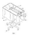
- FIG. 1illustrates a perspective view of a thermal treatment system in accordance with an embodiment of the present invention.
- FIG. 2illustrates an electrical schematic diagram of the heating unit employed by the thermal treatment system of FIG. 1 .
- FIG. 3illustrates a perspective view of a support assembly for a surgical instrument according to one embodiment of the invention, showing the support assembly coupled to the thermal treatment system of FIG. 1 .
- FIG. 4illustrates an exploded view in perspective of a support assembly for a surgical instrument coupled with a shelf (shown in part) of the thermal treatment system of FIG. 1 according to an embodiment of the invention.
- FIG. 5illustrates a view in perspective of a support assembly for a surgical instrument coupled with the shelf (shown in part) of the thermal treatment system of FIG. 1 according to another embodiment of the invention.
- FIG. 6illustrates an exploded view in perspective of a support assembly for a surgical instrument coupled with a shelf (shown in part) of the thermal treatment system of FIG. 1 according to a further embodiment of the invention.
- FIG. 6Aillustrates a partial view in cross-section of the support assembly of FIG. 6 .
- FIG. 7illustrates a view in perspective of a portion of a support assembly in accordance with an embodiment of the invention, the support assembly including a ramp for supporting portions of surgical instruments that are thermally treated using the thermal treatment system of FIG. 1 .
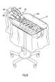
- FIG. 8illustrates a view in perspective of a tray for use with the thermal treatment system of FIG. 1 .
- FIG. 9illustrates a top view in plan of the support assembly for a surgical instrument and tray coupled to the thermal treatment system of FIG. 3 .
- FIGS. 10-12illustrate perspective views of a support assembly for a surgical instrument and tray coupled with a thermal treatment system according to additional embodiments of the invention.
- a systemincludes a cabinet including a shelf or ledge to support components of the scope, a basin positioned within the cabinet to contain and thermally treat a liquid bath, and a ramp structure disposed on the shelf of the cabinet that supports exposed scope optics above the liquid bath within the basin.
- the scope opticsreside outside of the bath in a dry state, thereby permitting the remaining scope portions within the bath to be thermally treated. This enables retrieval of enhanced images by the scope during a medical procedure.
- the systemcan further include a tray configured for insertion within the basin to protect a surgical drape used in combination with the system from being punctured by surgical instruments placed within the liquid bath.
- the traycan also include additional features such as apertures or holes provided within the tray to facilitate circulation of fluid within the basin during system operation.
- FIG. 1An example embodiment of a system for thermally treating a sterile medium (e.g., solution or liquid) is illustrated in FIG. 1 .
- the thermal treatment system 100includes a cabinet formed by a housing 105 which is in the form of a generally rectangular block defined by a lower wall and side walls of the housing.
- a top surface or shelf 120 of the cabinetoverlays the rectangular housing 105 and has length and width dimensions that extend beyond at least one side wall of the housing 105 so as to provide suitable surface areas for placement of items associated with surgical instruments that are treated by the system.
- a sterile mediume.g., solution or liquid
- the shelf 120is generally rectangular and is situated over housing 105 such that a central lengthwise axis of the shelf 120 corresponds with a central lengthwise axis of the housing 105 , thus forming ledge sections of the shelf 120 that extend beyond both longitudinal side walls of the housing 105 .
- the shelfcan be designed with any other suitable geometric configurations and/or spatial arrangements with respect to the cabinet housing, and some additional non-limiting examples are depicted in FIGS. 10-12 and described in further detail below.
- the shelf 120can also include a raised edge 121 disposed along one or more sides of the shelf, where the one or more raised edges 121 help to stabilize the support of items placed on the shelf during system operation.
- the cabinet housing 105attaches, via the lower housing wall, to one end of a support post 102 .
- the support post 102attaches at its other end to a generally circular base 104
- the base 104includes a plurality of legs 106 (e.g., five legs 106 as shown in FIG. 1 ) that extend transversely from and at circumferentially spaced locations along the base 104 .
- Each leg 106includes a caster wheel 108 disposed at its free end to facilitate movement of the system 100 in a variety of different directions, thus enabling easy mobility of the system.
- the systemcan include any other suitable support structure that supports the system at a suitable elevation and optionally facilitates movement of the system to different locations.
- a warming basin 110is provided in a recess that is defined through an opening in the shelf 120 and extending within the housing 105 of the cabinet.
- the basin 110may be of any suitable size and/or shape; however, by way of example only, the basin is illustrated having a substantially rectangular shape including an open top structure with generally vertical side walls 175 extending up from a generally horizontal floor 180 .
- a heater power switch 125 and a temperature controller/indicator 130are provided on the top surface 120 of the cabinet housing 105 , at a suitable location adjacent the warming basin 110 .
- a support hook 140can be provided on a side wall of the cabinet housing 105 (e.g., a front wall of the housing 105 as viewed in FIG. 1 ) and may support a system power cord (not shown). Electrical connections may be made to the cabinet via a power port 150 disposed on the housing front wall adjacent the hook 140 .
- fuse receptacles 160may be disposed on the housing front wall proximate the hook 140 to receive fuses in order to prevent damage to circuitry (such as the circuitry similar to that illustrated in FIG. 2 ) contained within the cabinet housing 105 .
- a sterile drape 170may be disposed over the shelf 120 and sides of the housing 105 .
- the power switch 125 and the controller 130disposed on the shelf 120 , are actuable manually through drape 170 .
- the portion of the drape 170 disposed as a liner in the basin 110serves as a sterile container or receptacle for a sterile medium 195 to be heated and placed therein.
- the sterile medium 195 treated by the thermal treatment system 100may include, but is not limited to, sterile liquid comprising a 0.80% to 0.95% sodium chloride solution (i.e., saline).
- the drape 170is preferably transparent and may be made from a material that is impervious to the sterile liquid and sufficiently soft and pliable to conform to the walls 175 and floor 180 of the basin 110 .
- the thickness of the drape 170is preferably minimized to render thermal transfer therethrough most efficient, yet the thickness is sufficient to resist tearing and puncturing during normal use.
- the drape 170may be made of materials commonly used in hospitals for surgical drapes and has a thickness, by way of example only, of approximately 4.5 to 6.0 mils.
- the drape 170may have any desired thickness.
- the drape 170may also be made of polyurethane film as disclosed for the drape in U.S. Pat. No. 4,934,152 (Templeton), the disclosure of which is incorporated herein by reference in its entirety.
- the drape 170may include sensors to detect the presence or absence of liquid within the basin and/or the presence of a drape leak. Examples of these types of drapes are disclosed in U.S. Pat. No. 6,810,881 (Faries, Jr. et al.) and U.S. Pat. No. 6,910,485 (Faries, Jr. et al.); as well as in U.S. Published Patent Application Nos. 2003/0231990 (Faries, Jr. et al.), 2004/0200483 (Faries, Jr. et al.), 2004/0200480 (Faries, Jr. et al.), and 2004/0208780 (Faries, Jr. et al.), the disclosures of which are incorporated herein by reference in their entireties.
- the drape 170may further include a preformed container portion or tray (described in further detail below) contoured to generally match the contour of the basin 110 .
- the preformed container portionis typically thicker than the remaining portions of the drape described above in order to resist puncture and enable the container portion to maintain the shape of the basin 110 .
- the container portionmay be made of a heavy gauge polyethylene/ionomer resin blend having a thickness of approximately 10 to 16 mils. The percentage of ionomer resin in the blend is in the approximate range of forty to seventy percent.
- the drapes described aboveare designed to be disposable after a single use and are provided pre-sterilized and prepackaged in a manner to preserve its sterile state during storage.
- the traycan be integral with the drape or, alternatively, separate from the drape. The tray can further be placed above or below the drape when placed within the housing basin during system operation.
- the drape 170is typically positioned over thermal treatment system 100 such that a portion of the drape is disposed in the basin 110 to form a drape receptacle.
- the drape 170forms a sterile field above the basin to maintain sterility of a sterile liquid 195 placed in the drape receptacle.
- objectse.g., medical instruments, containers, etc.
- An electrical circuitincludes a power source 210 connected in series with a temperature control unit 220 , a heater element or pad 200 , and the power control switch 125 (also illustrated in FIG. 1 ).
- the heater element 200is typically a thin, wafer-like member disposed along the bottom surface of the warming basin 110 , secured to the basin by a suitable pressure sensitive adhesive having efficient heat transfer characteristics.
- the heater element 200has smaller dimensions than those of the basin floor 180 and is disposed at the approximate center of the basin bottom surface.
- the heater element 200may be of any quantity (e.g., at least one), shape or size, and may include any configuration (e.g., strips, bars, segments, etc.) that covers the entirety or any portion of the basin 110 .
- the heater element 200may be implemented by any conventional or other type of heater or heating element (e.g., heating coils, etc.) that may be disposed on the basin at any suitable locations.
- the temperature control unit 220includes a device for adjusting current passing through heater element 200 so as to permit selective adjustment of the heat applied to the basin 110 (and thus the liquid in the basin).
- the power switch 125permits selective application and removal of current flow with respect to the heater element 200 .
- the heater element 200is controlled by the controller 220 in accordance with an entered desired temperature and temperatures measured by a temperature sensor 230 .
- the temperature sensor 230is preferably implemented by a conventional resistive temperature device (RTD) (e.g., a 1,000 Ohm RTD).
- RTDresistive temperature device
- the sensor 230may be implemented by any conventional or other type of temperature sensor, and may be disposed at any suitable location on the basin or within the cabinet housing 105 .
- the temperature sensor 230may be disposed adjacent the basin 110 to sense the temperature of the basin, the liquid contained therein, and/or the heater element 200 .
- the sensor 230is connected in series with a voltage source 240 and an indicator 250 .
- the voltage source 240 and the power source 210may be the same source, or the voltage for one may be derived from the other.
- the indicator 250measures the current through temperature sensor 230 , with the current being proportional to the sensed temperature.
- Both the indicator 250 and temperature controller 220may correspond, for example, to the temperature controller/indicator 130 described above.
- U.S. Pat. No. 5,333,326(Faries, Jr. et al.)
- U.S. Pat. No. 6,087,636Fearies, Jr. et al.
- the thermal treatment system 100 described above and illustrated in FIG. 1may have various configurations.
- the thermal treatment system 100may be configured to cool and/or congeal the medium to produce cooled liquid or surgical slush.
- the heater element 200may be replaced by refrigeration devices that are controlled in substantially the same manner described above.
- the thermal treatment system 100may include a plurality of basins warming and/or cooling a sterile medium as described above.
- the systemmay be configured to attach to a stand (as shown in the figures) or another system cabinet or may be configured as a stand-alone unit. Examples of different types of system configurations are disclosed in U.S. Pat. No. 5,333,326 (Faries, Jr.
- a conventional or other surgical scope 300typically includes a shaft member 310 with a distal portion 320 for insertion into a patient body.
- the distal portion 320typically includes a lens operable to capture and transmit images.
- An optics unit 330e.g., a lens, attachment structure to facilitate connection with a camera, etc.
- Fiber optics(not shown) generally extend along the interior of the shaft member 310 to transmit image data from the distal end of the scope to the optics unit 330 for conveyance to the surgeon, for example, via an eyepiece, camera, or other device that may be coupled to the optics unit 330 .
- each shaft member 310is placed within the basin 110 so as to be substantially submerged in liquid within the basin.
- a support assemblycomprising a ramp structure, as described in further detail below, supports the proximal end of each scope 300 , where one scope includes both an optics unit 330 and camera 332 while the other scope includes only an optics unit 330 .
- Scopes 300When surgical scopes 300 are warmed prior to use, the scope optics (i.e., the optics unit 330 and camera 332 ) must remain dry to protect those optics and prevent distortion of the image.
- Scopes 300are typically warmed in an insulated container (e.g., a THERMOS container) filled with warm liquid without temperature control. During treatment, the scopes come into contact with the sides and/or bottom of the container. The scopes 300 are warmed for several reasons, including enhancing image results, preventing infections, and maintaining normothermia. For example, a scope that is unwarmed prior to being inserted into a patient body may fog due to differences between the body temperature and scope temperature, thereby impeding or distorting the resulting image.
- scopesmay be warmed to minimize trauma caused to tissue in response to insertion of the scope into the patient body.
- the traumabasically results from the temperature difference between the scope and the tissue. Inserting a hot or cold scope may damage tissue, thereby leading to infections. Inserting a cold scope may lower the core body temperature of a patient, leading to hypothermia.
- a chemical wipe or spraymay alternatively be used to reduce fogging; however, the chemical may be inadvertently introduced into the patient, thereby causing complications.
- the present invention embodimentsenable medical personnel (e.g., operating room staff, etc.) to warm scopes 300 in a controlled environment (e.g., liquid bath) while maintaining the scope optics 330 and/or camera 332 attached to the scope 300 in a dry state.
- a controlled environmente.g., liquid bath
- the present invention embodimentsprovide a support system that stabilizes the scope, preventing its direct contact with the walls or floor of basin and/or with the drape.
- the thermal treatment system 100includes a support assembly comprising a ramp and a ramp mount.
- the rampis operable to elevate optics unit 330 and/or camera 332 above the surface (fluid line) of the temperature-controlled, liquid bath contained in the basin 110 .
- the ramp mountincludes suitable structure to secure the ramp to a portion of the shelf 120 that is in close proximity to the basin 110 . Any suitable structure can be provided to facilitate attachment or securing of the ramp structure to the shelf, and some non-limiting examples are depicted in FIGS. 4-6 and described below.
- a ramp 400 and ramp mount 450are shown.
- the ramp mount 450comprises a base plate that includes any suitable number (one or more) magnets 452 secured to one or both of the upper and lower surface of the ramp mount so as to facilitate a magnetic attraction and connection with a corresponding magnetic surface of the shelf 120 and/or with a corresponding magnetic surface disposed on an underside of the ramp 400 .
- the ramp 400includes a raised lip portion 402 that extends around the outer periphery of the lower surface of the ramp.
- the ramp 400 and ramp lip portion 402are suitably dimensioned such that the lip portion 402 fits around outer peripheral edge portions of the ramp mount 450 when the ramp is connected with the ramp mount, where the lip portion 402 engages with the outer peripheral edge portions of the ramp mount 450 in a snap fitting engagement.
- the ramp 400can further be bonded to the ramp mount 450 in any suitable manner to prevent removal of the ramp from the ramp mount (e.g., via heat welding to seal the ramp with the ramp mount).
- the ramp mount 450can be affixed directly to a portion of the cabinet shelf 120 in any other suitable manner including, without limitation, using ultrasonic energy, heat welding, solvents, adhesives, RF welding techniques, mechanical affixing via screws or other fasteners, or any other appropriate or conventional attachment process.
- the ramp and ramp mountcan be constructed of any one or more suitable, medical grade materials including, without limitation, silicone or other suitable plastics and/or metal materials such as stainless steel.
- suitable, medical grade materialsincluding, without limitation, silicone or other suitable plastics and/or metal materials such as stainless steel.
- each of the ramp and shelffurther include suitable magnetic materials to facilitate securing by magnetic attraction of the ramp and/or shelf to the magnets disposed on the ramp mount.
- the design of the support assembly as depicted in FIG. 4facilitates arrangement of the drape in a number of different configurations with respect to the ramp 400 and ramp mount 450 .
- the drapecan be placed upon the shelf 120 prior to assembly of the ramp 400 and ramp mount 450 upon the shelf, such that the drape is disposed between the ramp mount and the cabinet shelf.
- the ramp 400 and ramp mount 450can first be connected to the cabinet shelf 120 , followed by placement of the drape over the cabinet shelf.
- the drapecan be disposed over the shelf 120 , ramp 400 and ramp mount 450 or, alternatively, over just the cabinet shelf while leaving the ramp and ramp mount exposed.
- the drapecan be placed over the shelf 120 and ramp mount 450 secured to the shelf, followed by securing of the ramp 400 to the ramp mount 450 such that the drape is disposed between the ramp and the ramp mount.
- the ramp and/or ramp mountare not covered by the drape, the ramp and/or ramp mount are preferably provided in a sterile condition for use with the system 100 (e.g., the ramp and/or ramp mount can be provided in a sterilized package prior to use).
- the drapecan be designed with a cut-out section or other suitable geometry that provides for substantial or complete coverage of the cabinet shelf while leaving the ramp and/or ramp mount uncovered and exposed.
- the embodiments depicted in the figuresshow the ramp and ramp mount secured to the shelf and exposed with the drape not overlying or covering these components.
- a ramp mount 450 - 1is configured in the form of a boot that is secured in any suitable manner to the cabinet shelf 120 (e.g., in any of the ways described above for the embodiment of FIG. 4 ).
- the ramp mount 450 - 1includes outer lip portions 454 that extend upward and away from the shelf 120 along the peripheral edges of two opposing sides of the ramp mount.
- the ramp mount 450 - 1 and ramp 400 - 1are suitably dimensioned such that the ramp 400 - 1 fits between the lip portions 454 so as to be firmly secured or fixed to the cabinet shelf 120 via the ramp mount 450 - 1 .
- the ramp and ramp mountcan be constructed of any suitable materials including, without limitation, silicone or other medical grade plastics or metal materials.
- the ramp 400 - 1When the ramp 400 - 1 is seated on the ramp mount 450 - 1 between the lip portions 454 , the ramp is held in a frictional fit engagement within the ramp mount. This allows the ramp to be removed from the ramp mount after use for disposal or recycle (i.e., re-sterilization and re-use).
- the ramp 400 - 1can be secured to the ramp mount 450 - 1 using any suitable technique (e.g., using ultrasonic energy, heat welding, solvents, adhesives, RF welding techniques or any other appropriate or conventional attachment process).
- the drapecan be placed between cabinet shelf and ramp mount, placed between ramp mount and ramp, placed over the cabinet shelf, ramp mount and ramp, or placed over the cabinet shelf while leaving ramp and ramp mount exposed during system operation.
- a ramp mount 450 - 2comprises a generally rectangular base plate including indentations or grooves 456 extending along opposing side wall surfaces of the base plate.
- the ramp mount 450 - 2can be secured in any suitable manner to the cabinet shelf 120 (e.g., in any of the ways described above for the embodiment of FIG. 4 ).
- the ramp 400 - 2includes lip portions extending along the lower edges of the opposing wall surfaces of the ramp that correspond with the opposing surfaces of the ramp mount 450 - 2 including grooves 456 . As can be seen from the cross-sectional view of the ramp depicted in FIG.
- each of the lip portions of the ramp 400 - 2include an inwardly extending tab 404 that extends along the side wall surface of the ramp and a rolled edge 405 that has a generally U-shaped cross-sectional configuration.
- the ramp 400 - 2has a hollow interior and, upon placement of the ramp over the ramp mount, the lower sidewall surface portions of the ramp are frictionally fit around the ramp mount 450 - 2 with tabs 404 fitting and locking within grooves 456 in a snap fitting connection.
- the ramp 400 - 2can be snap fit and removably secured to the ramp mount 450 - 2 , where the rolled edges 405 of the ramp can be pressed to dislodge tabs 404 from grooves 456 when it is desired to remove the ramp from the ramp mount.
- the ramp 400 - 2can be disposed after a single use or recycled (re-sterilized) for additional uses.
- the ramp and ramp mountcan be constructed of any suitable materials including, without limitation, silicone or other medical grade plastics or metal materials, preferably using materials that facilitate suitable flexibility and resiliency of the rolled edge portions to facilitate removal of the ramp from the locked engagement with the ramp mount.
- the drapecan be placed between cabinet shelf and ramp mount, placed between ramp mount and ramp, placed over the cabinet shelf, ramp mount and ramp, or placed over the cabinet shelf while leaving ramp and ramp mount exposed during system operation.
- ramp 400is designed to support one or more scopes at their proximal ends including optics components.
- ramp 400includes exterior side walls 410 , 411 , front wall 412 and rear wall 413 .
- the rampis at least partially hollow between its front, rear and side walls to facilitate insertion of at least a portion of the ramp mount 450 within the ramp during connection of the ramp and ramp mount.
- the rampcan also include a lip portion at its lower peripheral edges to provide a locking (e.g., snap fitting) engagement with the ramp mount.
- Ramp 400includes an angled and multi-faceted upper wall or scope receiving portion that includes a slot and various angled or inclined surfaces designed to support and retain optics components at the proximal end of a scope 300 (e.g., the optics unit 330 and camera 332 ) during thermal treatment of one or more scopes with system 100 .
- the scope receiving portion of the ramp 400includes opposing interior side walls 414 , 415 that correspond with exterior side walls 410 , 411 .
- Each interior side wall 414 , 415is tapered or angled outward and toward its corresponding exterior side wall 410 , 411 such that a distance between the interior side wall and its corresponding exterior side wall decreases in a direction from a lower end of the ramp 400 that connects with ramp mount 450 to an upper, free end of the ramp.
- each interior side wall 414 , 415can extend outward at an angle of about 30° or less, where the angle is measured at the intersection between the interior side wall and an imaginary plane that is oriented parallel with respect to the cabinet shelf 120 when the ramp is connected with the shelf.
- the angled interior side walls 414 , 415minimize side movement and provide increased or enhanced stability for one or more scopes supported by the ramp 400 during system operation.
- the scope receiving portionfurther includes a generally planar camera receiving surface 420 and a generally rounded, concave slot 422 defined within the camera receiving surface 420 .
- the camera receiving surface 420 and concave slot 422are angled at a suitable ramped incline as these surfaces extend from the front wall 412 to the rear wall 413 .
- camera receiving surface 420is suitably dimensioned to receive, hold and retain the camera 332 of a first scope 300 , while at least a portion of the shaft 310 including distal end 320 of the scope is submerged in thermal treatment liquid within the basin 110 .
- a second scope 300can also be held by the ramp 400 simultaneously with the first scope, where the concave slot 422 receives, holds and retains the optics unit 330 of the second scope while at least a portion of the shaft 310 including the distal end 320 of the second scope is submerged in thermal treatment liquid within the basin 110 .
- the front wall 412includes a lip portion 424 that extends slightly above and beyond surface 420 and slot 422 so as to provide an abutting ledge or stop for portions of the camera 332 and optics unit 330 .
- the lip portion 424 of the front end wall 412provides a stop which prevents the camera and optics unit from sliding down the ramp 400 and into the basin 110 during thermal treatment of the first and second scopes.
- the dimensions of the scope receiving portion as well as other portions of the ramp 400are configured to hold portions of one or more scopes with suitable stability.
- the dimension of each interior side wall 414 , 415 between the camera receiving surface 420 and the upper, free end of the ramp 400can be suitably dimensioned to engage with at least about 1 ⁇ 3 of a corresponding surface portion of the scope camera 332 when the camera is placed on surface 420 .
- the width dimension of the ramped or inclined scope receiving portion that includes camera receiving surface 420 and concave slot 422 at the front end wall 412 of the ramp 400can be the same or similar to the width dimension defined between the vertical side walls 175 of the basin 110 .
- the width dimension between exterior side walls 410 , 411 at the front end wall 412 of the ramp 400can be the same or similar to the width dimension between exterior side wall surfaces of the cabinet housing 105 .
- a tray 500is provided that is suitably dimensioned and configured to be inserted within the basin 110 of the system 100 , where the tray has length and width dimensions that are slightly smaller than those of the basin.
- the tray 500is constructed of suitable materials including, without limitation, medical grade plastics and/or metal materials, to prevent puncture of the tray by medical instruments that are placed and thermally treated within the tray.
- the traycan be made of a heavy gauge polyethylene/ionomer resin blend having a thickness of approximately 10 to 16 mils, where the percentage of ionomer resin in the blend can be in the approximate range of forty to seventy percent.
- the tray 500can further be designed for placement above or below the drape 170 that is placed within the basin 110 .
- the tray 500is designed to overlay the drape 170 (i.e., the drape is disposed between the basin and the tray) in order to protect the drape from puncture or rupture during thermal treatment of medical items and thus ensure a sterile barrier is maintained during system operation.
- the tray 500provides a bather between the scope 300 and the drape 170 to protect the drape from potentially overheating and melting due to light irradiation from a light source disposed within the scope.
- the tray 500can be integrated with the drape 170 so as to be a single unit or, alternatively, the tray can be designed as a separate component that can be placed over the drape after the drape is inserted within the basin 110 .
- the traycan be integrated with the drape to form a single unit using any suitable technique such as ultrasonic energy, heat welding, solvents, adhesives, RF welding techniques or any other appropriate or conventional attachment process.
- the trayis sterilized (either with the drape when both are integrated as a single unit, or separately from the drape) prior to being used.
- the tray 500includes side walls 502 , 504 , a front wall 506 , a rear wall 508 , a bottom wall 510 and a reservoir defined between the walls to receive thermal treatment fluid when the tray is placed within the basin 110 .
- the bottom wall 510 of the tray 500tapers to form a decline or ramped surface from the front wall 506 to the rear wall 508 of the tray.
- a gapis formed between the generally horizontal floor 180 of the basin and the bottom wall 510 of the tray, where the gap increases in dimension as the bottom wall 510 extends from the rear wall 508 to the front wall 506 of the tray.
- the bottom wall 510 of the tray 500further includes a plurality of indentations or grooves 520 having a general V-shape, where the grooves 520 are aligned along the lengthwise dimension of the bottom wall.
- a plurality of generally circular openings or holes 530are also provided extending through the bottom wall 510 of the tray 500 and arranged along the lengthwise dimension of the bottom wall and at spaced locations between and/or on either side of the V-shaped grooves 520 . As depicted in FIG. 8 , two holes 530 are provided on either side of each V-shaped groove 520 . However, any other suitable number, arrangement and/or configuration of holes and grooves can be provided along the bottom wall of the tray.
- a top wall 540 of the tray 500is coupled via a hinge connection with rear wall 508 so as to facilitate a partial closing or forming a partial cover over the tray reservoir.
- the hinge connectioncan comprise a plastic material of reduced thickness in relation to the top wall 540 and bottom wall 510 which forms a “living hinge” connection to allow bending and pivotal movement of the top wall with respect to the bottom wall.
- the top wall 540is depicted in an open position in FIG. 8 , whereas the top wall 540 is flipped (via the hinge connection) to a closed position overlying the reservoir as depicted in FIG. 9 .
- the hinged top wall 540when in its closed position overlaying the reservoir, is suitably dimensioned to cover a portion of the shaft member 310 of scope 300 including distal end 320 when the camera 332 of the scope rests upon the camera receiving surface 420 of the ramp 400 (as can be seen in FIG. 9 ). This further enhances the stability of the system in maintaining portions of the scope within the thermal treatment fluid while preventing portions such as the camera and optics unit of the scope from inadvertently falling within the tray reservoir.
- a further feature of the tray 500is that interior wall portions within the reservoir of the tray 500 , including rear wall 508 and/or any other portions that face the distal end 320 of the scope shaft member 310 when the scope is thermally treated within the tray reservoir, are white in color.
- the one or more white colored interior wall portions within the trayallows for calibration of the camera (e.g., via white balancing) while it is being thermally treated by the system 100 .
- the system 100is initially set up by installing the ramp 400 and/or ramp mount 450 with respect to the cabinet shelf 120 in the manner described above (e.g., utilizing any of the embodiments of FIGS. 4-6 ).
- the drape 170 and tray 500are also installed in the basin in the manner described above, with the drape 170 and tray 500 extending within the basin 110 and the drape further extending over the cabinet shelf 120 and optionally over the ramp 400 and/or ramp mount 450 .
- a sterile treatment fluidis provided within the reservoir of the tray 500 and basin 110 .
- the portion of the shaft member 310 including distal end 320 of a first scope 300is placed in the reservoir of tray 500 while the camera 332 is placed on camera receiving surface 420 of the ramp 400 .
- a second scope 300can also be thermally treated (as shown in FIG. 3 ) at the same time as the first scope by placement of the shaft member 310 including distal end 320 of the second scope within the tray reservoir while placing scope optics unit 330 within the concave slot 422 of the ramp 400 .
- the corresponding sloped or ramped camera receiving surface 420 and tray bottom wall 510ensure that a sufficient portion of the scope shaft member 310 including distal end 320 for each of the first and second scopes is submerged in thermal treatment fluid within the tray reservoir.
- the lip portion 424 and design of the scope receiving portion of the ramp 400 as well as the grooves 520 in the tray bottom wall 510prevent or substantially limit the potential for the scope camera 332 of the first scope and the scope optics units 330 of the first and second scopes from slipping off the ramp 400 and falling into the tray reservoir. Therefore, the scope optics unit for each scope and also the camera for the first scope is maintained in a dry state, while the scope shaft member 310 for each scope is primarily placed into the thermal treatment fluid bath within the tray reservoir.
- the sterile thermal treatment bath disposed within the tray reservoir and within the basin 110can be heated (or cooled) to the desired temperature via manipulation of the controller 130 as described above and depicted in FIG. 2 .
- the bathmay be heated (or cooled) before any scope 300 is positioned in the ramp 400 and tray 500 .
- the scope 300absorbs the proper amount of thermal energy from the thermal treatment bath maintained within basin 110 , while the optics unit 330 and camera 332 of the first and second scopes 300 remain dry, thereby preventing image distortion caused by liquid contacting exposed optics.
- the holes 530 within the tray bottom wall 510facilitate the circulation of thermal treatment fluid between the basin 110 and the tray reservoir, which prevents stagnation of the thermal treatment fluid and promotes uniform thermal treatment of each scope.
- the ramp 400 and the top wall 540 and grooves 520 of the tray 500effectively stabilize each scope as it is thermally treated by system 100 . This allows for accurate temperature warming of selected portions of the scope, which, in turn, reduces tissue trauma, maintains normothermia, and enables the scope optics unit to remain dry for clear viewing of images.
- puncture or damage to any one or more of the scope 300 , the basin 110 , or the drape 170is avoided since the tray 500 prevents the distal end 320 of the scope from directly contacting the basin or drape.
- the systemcan be modified such that the cabinet shelf 120 has a different configuration from that which is depicted in FIGS. 1-9 .
- FIGS. 10-12a thermal treatment system is depicted in each figure that is substantially similar to the system of FIGS. 1-9 , with the exception that the cabinet shelf 120 has a different geometric design.
- the cabinet shelf 120 - 1has a generally rectangular configuration with ledge portions that extend beyond the opposing side walls of the cabinet housing and raised edges 121 located along one or more sides of the shelf.
- the shelf 120 - 1further includes a generally rectangular section 602 that extends from a longitudinal end of the shelf and has length and width dimensions that are smaller in relation to the rectangular portion of the shelf 120 - 1 .
- the extended section 602is suitably dimensioned such that the ramp 400 and ramp mount 450 are secured to this extended section.
- the ledge portions of the cabinet shelf 120 - 1are suitably dimensioned to support tubing 600 connected with the scope 300 .
- the tubing 600typically contains wiring for the camera and scope (e.g., electrical wiring, fiber optic cables, etc.).
- the raised edges 121 of the shelf 120 - 1provide a bather to prevent or inhibit the tubing 600 from falling off the shelf.
- a generally rectangular shelf 120 - 2(including raised edges 121 along one or more sides of the shelf) is provided that is offset from the cabinet housing 105 such that a ledge portion of the shelf extends beyond one side wall of the cabinet housing.
- This ledge portionis suitably dimensioned to receive and support tubing 600 connected with the scope 300 .
- the cabinet shelf 120 - 3is aligned with respect to the cabinet housing 105 in a similar manner as that which is depicted in FIG. 11 (with a ledge portion of the shelf extending beyond one side wall of the cabinet housing and raised edges 121 along one or more sides of the shelf).
- shelf 120 - 3further includes a generally rectangular section 604 that extends from a longitudinal end of the shelf and has length and width dimensions that are smaller in relation to the rectangular portion of the shelf 120 - 3 .
- the extended section 604is suitably dimensioned such that the ramp 400 and ramp mount 450 are secured to this extended section.
- Tubing 600 for the scope 300is supported by the ledge portion of the shelf 120 - 3 and connects with the scope 300 .
- cabinet shelfOther embodiments of the cabinet shelf are also possible that facilitate placement of the ramp and ramp mount on the shelf in proximity with the basin defined within the cabinet housing and further provides adequate surface area on the shelf to permit placement and support of tubing for fiber optics components and/or other instruments associated with the medical items being thermally treated by the system.
- the shelfcan be formed as part of the cabinet housing for system 100 or, alternatively, the shelf can be provided as a kit for retrofitting or after market installation with existing systems.
- the ramp and/or ramp mountcan be included with the shelf in a kit or provided separately.
- Each of the shelf, ramp and ramp mountcan be designed for disposal after a single use or, alternatively, recycled for additional uses (provided appropriate sterilization of the components has been applied between uses).
- thermal treatment system instrument support assemblyand method of selectively thermally treating medical instrument portions.
- present invention support assembly structure and/or thermal treatment systemsare not limited to the applications described herein, but may be utilized for any types of medical or other items to selectively thermally treat any portions of those items.
- the warming, cooling, ramp and ramp mount, support tray, basin systems and their corresponding cabinet housings and cabinet shelf sections, assemblies or housingsmay be of any shape or size and may be constructed of any suitable materials.
- the systemsmay include any quantity of heating and/or cooling basins in any combinations.
- the basin of the systemsmay be of any shape or size, may be constructed of any suitable thermal conducting materials (e.g., stainless steel, etc.), and may be disposed at any suitable locations on or within the housings.
- the systemsmay include any conventional or other heating and/or refrigeration units to thermally treat any type of sterile medium or other substance to any desired temperature.
- the heating unitmay include any conventional or other heating device and components to control heating of a basin to any desired temperature (e.g., preferably to temperatures near (e.g., above, at or below) body temperature, such as temperatures in the approximate range of 60° F.-160° F.).
- the heater elementmay be of any quantity (e.g., at least one), shape or size, and may include any configuration (e.g., strips, bars, O-shaped segments, U-shaped segments or any other segments, etc.) that covers the entirety or any portion of a basin.
- the heater elementmay be attached to a basin via any conventional or other fastening techniques (e.g., any type of adhesives, brackets, etc.).
- the heater elementmay be implemented by any conventional or other type of heater or heating element (e.g., heating coils, etc.) that may be disposed on or proximate a basin at any suitable locations.
- a cooling unitmay include any conventional or other cooling or refrigeration device and components to control cooling of a basin to any desired temperature (e.g., preferably to temperatures near or below the freezing temperature of the sterile liquid or medium, such as temperatures in the approximate range of ⁇ 32° F. to 32° F.).
- the various power switches and controllers of the systemsmay be implemented by any conventional or other power and control devices and may be disposed on the systems at any suitable locations.
- the temperature sensormay be implemented by any conventional or other temperature sensing device (e.g., infrared, RTD, etc.) and may be disposed at any location on or proximate a basin or within the systems.
- the basins of the systemsmay be disposed in any arrangement or at any suitable locations on the systems.
- the systemsmay thermally treat (e.g., heat or cool) any type of medium or liquid, while a cooling basin may further include any type of conventional or other dislodgement mechanism, such as those described in the aforementioned patents.
- the drapes employed with the heating, cooling and basin systemsmay be of any size or shape, and may be constructed of any suitable materials.
- the drapesare preferably transparent or translucent to facilitate manipulation of controls through the drape; however, these drapes may have any degree of transparency (e.g., including opaque).
- the drapesmay be manipulated in any fashion with any portions of the drapes serving as a drape receptacle within a corresponding basin.
- the drapesmay be of sufficient size to accommodate and form drape receptacles within any quantity of thermal treatment system basins.
- the drapemay facilitate placement of any types of objects (e.g., instruments, containers, etc.) within the basin.
- the drapesmay be integrated in any suitable manner with any portion of the trays, ramps and/or ramp mounts.
- the scope optics support assemblymay be of any quantity, size or shape, may be disposed on any part of the drape and/or cabinet shelf and may be constructed of any suitable materials.
- the support assemblymay be a separate unit or formed integral with and/or attached to the drape and/or preformed container portion via ultrasonic energy, heat welding, solvents, adhesives, RF welding techniques or any other attachment process.
- the support assemblymay include a ramp and ramp mount that are formed integral with each other, with the cabinet shelf and/or with the drape.
- the shelfcan be a separate unit that mounts to the cabinet housing or, alternatively, formed as an integral part of the cabinet housing.
- the shelfcan have any suitable shape, design and configuration suitable to support the scope optics support assembly and provide surface areas for supporting components of the medical items being thermally treated by the system.
- the shelfcan be constructed of any one or more suitable medical grade plastics, metals and/or other materials.
- the support membersmay include any quantity of support surfaces each to accommodate any quantity or portions of scopes or other objects.
- the support membersmay include any configuration to form support surfaces of any quantity, shape or size to receive any medical or other objects.
- the cabinet shelfmay include any quantity of ramp structures and/or other support members disposed at any locations to elevate and/or submerge any portions of medical or other items.
- the ramp and ramp supportcan include any suitable configuration to facilitate mounting of the ramp structure to the cabinet shelf.
- the rampcan be formed integrally with the ramp mount or as a unit that is separable from the ramp mount.
- the ramp mountcan be formed integrally with the cabinet shelf or, alternatively, as a unit that is separable from the cabinet shelf.
- any one or more of the ramp, ramp mount, and cabinet shelfcan be provided as a kit for installation and use with the thermal treatment system.
- the trayscan be configured to receive and submerge any number and types of medical items or portions of medical items. Any suitable number of openings and/or ridges or grooves may be provided in any internal wall portions of the trays to facilitate fluid circulation between the tray and basin and to further enhance stability of the medical items placed within the tray. Any suitable number of top wall portions can be provided for the tray to selectively close one or more portions of the tray reservoir.
- the traycan be designed as a disposable unit limited to a single use. Alternatively, the tray can be configured for re-sterilization and re-use. The tray can be integrated with or provided as a separate unit from the drape.
- the control circuit, power port, fuse holders, and/or other componentsmay be disposed within the systems at any suitable locations and may be implemented by any conventional or other circuitry components arranged in any desired fashion to perform the described functions.
- the temperature controllermay be implemented by any conventional or other temperature controller and include any desired devices for entering a temperature (e.g., buttons, keypad, etc.).
- the basin power switch of the systemsmay be implemented by any conventional or other switching device, while the fuses may be implemented by any conventional fuse or other limiting device and may be configured for any current or voltage levels.
- the power cordmay be implemented by any conventional or other cord or cable and be configured to accommodate any desired power signals.
- the systemmay utilize any type of power source (e.g., batteries, wall outlet jack, AC, DC, etc.).
- top”, “bottom”, “front”, “rear”, “side”, “height”, “length”, “width”, “upper”, “lower”, “vertical” and the likeare used herein merely to describe points of reference and do not limit the present invention to any particular orientation or configuration.
- the inventionmakes available a novel thermal treatment system instrument support assembly and method of selectively thermally treating medical instrument portions, wherein a system thermally treats surgical scopes and/or other medical instruments in a temperature controlled liquid bath while maintaining optics of the scope (or other portions of the instruments) in a dry state.
Landscapes
- Health & Medical Sciences (AREA)
- Life Sciences & Earth Sciences (AREA)
- Surgery (AREA)
- Medical Informatics (AREA)
- Molecular Biology (AREA)
- Veterinary Medicine (AREA)
- Public Health (AREA)
- General Health & Medical Sciences (AREA)
- Animal Behavior & Ethology (AREA)
- Engineering & Computer Science (AREA)
- Biomedical Technology (AREA)
- Heart & Thoracic Surgery (AREA)
- Nuclear Medicine, Radiotherapy & Molecular Imaging (AREA)
- Physics & Mathematics (AREA)
- Biophysics (AREA)
- Radiology & Medical Imaging (AREA)
- Pathology (AREA)
- Optics & Photonics (AREA)
- Apparatus For Disinfection Or Sterilisation (AREA)
Abstract
Description
Claims (31)
Priority Applications (1)
| Application Number | Priority Date | Filing Date | Title |
|---|---|---|---|
| US13/223,378US8710407B2 (en) | 2010-09-02 | 2011-09-01 | Selective thermal treatment of medical instrument portions with thermal treatment system instrument holder |
Applications Claiming Priority (2)
| Application Number | Priority Date | Filing Date | Title |
|---|---|---|---|
| US37954710P | 2010-09-02 | 2010-09-02 | |
| US13/223,378US8710407B2 (en) | 2010-09-02 | 2011-09-01 | Selective thermal treatment of medical instrument portions with thermal treatment system instrument holder |
Publications (2)
| Publication Number | Publication Date |
|---|---|
| US20120187104A1 US20120187104A1 (en) | 2012-07-26 |
| US8710407B2true US8710407B2 (en) | 2014-04-29 |
Family
ID=45773321
Family Applications (1)
| Application Number | Title | Priority Date | Filing Date |
|---|---|---|---|
| US13/223,378Active2032-06-17US8710407B2 (en) | 2010-09-02 | 2011-09-01 | Selective thermal treatment of medical instrument portions with thermal treatment system instrument holder |
Country Status (3)
| Country | Link |
|---|---|
| US (1) | US8710407B2 (en) |
| EP (2) | EP2700375B1 (en) |
| WO (1) | WO2012029049A2 (en) |
Cited By (3)
| Publication number | Priority date | Publication date | Assignee | Title |
|---|---|---|---|---|
| US20160206365A1 (en)* | 2011-10-03 | 2016-07-21 | Covidien Lp | External cooling devices and systems for surgical instruments |
| US20220105651A1 (en)* | 2019-11-07 | 2022-04-07 | Land O'lakes, Inc. | Food slicer assembly |
| US20220176053A1 (en)* | 2020-12-09 | 2022-06-09 | Matthew Arnall | Device for heating endotracheal tubes preparatory to nasal intubation |
Families Citing this family (16)
| Publication number | Priority date | Publication date | Assignee | Title |
|---|---|---|---|---|
| US8789534B2 (en) | 2008-04-09 | 2014-07-29 | Patented Medical Solutions, Llc | Method and apparatus for warming medical solutions in a thermal treatment system employing a removable basin |
| US9283042B2 (en)* | 2012-09-11 | 2016-03-15 | Ecolab Usa Inc. | Scope pillow drape with extension shelf and power cord hook |
| US20140116647A1 (en)* | 2012-10-31 | 2014-05-01 | Bruce Kannry | Scope cradle |
| EP3046497B1 (en)* | 2013-09-18 | 2021-06-30 | Covidien LP | Laparoscopic visualization system |
| AU2014354716B2 (en)* | 2013-11-28 | 2018-12-06 | Alcon Inc. | Ophtalmic surgical systems, methods, and devices |
| EP3139812B1 (en) | 2014-05-06 | 2019-01-09 | Buffalo Filter LLC | Laparoscope and endoscope cleaning and defogging device |
| US11612305B1 (en)* | 2014-06-06 | 2023-03-28 | Hyunsuk Lee | Receptacle for a laryngoscope and method of using same |
| JP6714960B2 (en)* | 2015-03-02 | 2020-07-01 | 諭 粟津 | Endoscope holding member, endoscope holding method, cart having the same, cleaning sink, cleaning/disinfecting apparatus, stand, and endoscope storage |
| US10398296B2 (en) | 2017-03-07 | 2019-09-03 | Carefusion 2200, Inc. | Trocar assembly with a cleaning element for use during a laparoscopic procedure |
| US10368905B2 (en) | 2017-03-07 | 2019-08-06 | Carefusion 2200, Inc. | Trocar assembly with a cleaning element for use during a laparoscopic procedure |
| US10201396B2 (en) | 2017-03-07 | 2019-02-12 | Carefusion 2200, Inc. | Trocar assembly with a cleaning element for use during a laparoscopic procedure |
| WO2018222754A1 (en) | 2017-05-31 | 2018-12-06 | Carefusion 2200, Inc. | Trocar assembly with a movable cleaning element |
| CN208298251U (en)* | 2018-04-17 | 2018-12-28 | 深圳市道通科技股份有限公司 | The caliberating device and system of vehicle-mounted camera |
| CN109124556A (en)* | 2018-07-25 | 2019-01-04 | 韩智强 | A kind of laparoscopic surgery camera lens attemperator |
| US11992347B2 (en)* | 2020-02-21 | 2024-05-28 | Canon U.S.A., Inc. | Medical device cart with a tilted holder |
| WO2025046405A1 (en)* | 2023-08-30 | 2025-03-06 | Alcon Inc. | Systems including a wireless remote and tray |
Citations (122)
| Publication number | Priority date | Publication date | Assignee | Title |
|---|---|---|---|---|
| US2174425A (en) | 1937-08-09 | 1939-09-26 | Schlumbohm Peter | Cooking utensil |
| US2323356A (en) | 1941-04-08 | 1943-07-06 | Rosay Joseph | Liner and holder therefor |
| US2599192A (en) | 1949-02-07 | 1952-06-03 | Iva L Miller | Shelf for wash tubs |
| US2613511A (en) | 1948-04-14 | 1952-10-14 | Flakice Corp | Ice-making machine |
| US2807701A (en) | 1955-03-31 | 1957-09-24 | Hankscraft Co | Egg cooker |
| US3249070A (en) | 1963-09-11 | 1966-05-03 | George L Day | Instrument tray with disposable field sheet |
| US3685507A (en) | 1970-11-02 | 1972-08-22 | Readi Temp | Heat transfer unit |
| US3807954A (en) | 1972-06-16 | 1974-04-30 | H Mcdonald | Sterilizing apparatus for medical instruments |
| US3869596A (en) | 1973-09-28 | 1975-03-04 | Safeway Products Inc | Cookware heater |
| US3902484A (en) | 1972-02-07 | 1975-09-02 | Kimberly Clark Co | Disposable surgical drape |
| US3942510A (en) | 1974-08-21 | 1976-03-09 | General Kinetronics | Heating device |
| US4053954A (en) | 1976-06-17 | 1977-10-18 | George Chapman | Bathtub caddy |
| US4270067A (en) | 1977-10-18 | 1981-05-26 | Trans-Canada Life-Ware Limited | Electric frying pan |
| US4284880A (en) | 1979-02-06 | 1981-08-18 | International Foodservice Equipment Systems, Inc. | Heating well |
| US4393659A (en) | 1982-06-01 | 1983-07-19 | Taylor Freezer Company | Method and apparatus for producing sterile slush ice |
| US4458139A (en) | 1981-08-05 | 1984-07-03 | Breville Holdings Pty., Limited | Electrically heated cooking utensil |
| US4474016A (en) | 1983-03-04 | 1984-10-02 | Baxter Travenol Laboratories, Inc. | Sterile cooling system |
| US4516564A (en) | 1981-11-28 | 1985-05-14 | Japan Pionics Co., Ltd. | Heat generating body |
| US4522041A (en) | 1978-12-23 | 1985-06-11 | Firma Ireks Arkady Gmbh | Ice-cream maker |
| US4625098A (en) | 1984-10-16 | 1986-11-25 | Joe Do S | Cookware having integrally formed natural stone bottoms and method of manufacturing the same |
| US4782835A (en) | 1982-05-07 | 1988-11-08 | Michael Litman | Refill unit for portable heat treatment system |
| US4828876A (en) | 1985-02-06 | 1989-05-09 | Sharp Kabushiki Kaisha | Production of photoelectric conversion film and contact type image sensor |
| US4869271A (en) | 1988-12-16 | 1989-09-26 | Kimberly-Clark Corporation | Bi-lateral surgical drape |
| US4903710A (en) | 1987-01-06 | 1990-02-27 | Jessamine John G | Surgical isolation drapes |
| US4934152A (en) | 1989-07-10 | 1990-06-19 | Saniserv Inc. | Apparatus and method for producing sterile slush and heated sterile liquid |
| US4967061A (en) | 1989-10-10 | 1990-10-30 | Sonne Medical, Inc. | Heated basin |
| US5040699A (en) | 1989-05-15 | 1991-08-20 | Gangemi Ronald J | Fluid compounding method and apparatus |
| US5042455A (en) | 1989-08-18 | 1991-08-27 | Pmt Corporation | Fluid warmer |
| US5042981A (en) | 1986-06-25 | 1991-08-27 | Fuchelman Sociedad Anonima | Assembly comprising a surgical drape and a contour-type electrosurgical dispersive electrode, and method for its use |
| USRE33854E (en) | 1989-02-03 | 1992-03-24 | sterilizable sheathpe with .[.heat.]. | |
| US5129033A (en) | 1990-03-20 | 1992-07-07 | Ferrara Janice J | Disposable thermostatically controlled electric surgical-medical irrigation and lavage liquid warming bowl and method of use |
| US5163299A (en) | 1992-03-16 | 1992-11-17 | O.R. Solutions, Inc. | Method and apparatus for producing sterile slush |
| US5174306A (en) | 1990-04-30 | 1992-12-29 | Scherer Healthcare Ltd. | Method and apparatus for forming a sterile field |
| US5310524A (en) | 1992-02-11 | 1994-05-10 | Minntech Corporation | Catheter reprocessing and sterilizing system |
| US5331820A (en) | 1993-09-23 | 1994-07-26 | O.R. Solutions, Inc. | Method and apparatus for forming and collecting surgical slush |
| US5333326A (en) | 1993-03-16 | 1994-08-02 | O. R. Solutions, Inc. | Method and apparatus for producing surgical slush and heated sterile liquid |
| US5345063A (en) | 1990-08-10 | 1994-09-06 | Allied Precision Industries, Inc. | Nestable stackable heated bowl with removable thermostatically controlled electric heating element |
| US5351675A (en) | 1992-08-14 | 1994-10-04 | The Kendall Company | Method and apparatus for preheating an optical instrument prior to use thereof in a medical procedure |
| US5363746A (en) | 1990-10-29 | 1994-11-15 | Gordon Ellis D | Automatic food preparation device |
| US5374278A (en) | 1989-11-14 | 1994-12-20 | United States Surgical Corporation | Method and apparatus for heat tipping sutures |
| US5374813A (en) | 1992-10-15 | 1994-12-20 | Life Surgery, Inc. | Surgical instrument recycling and tracking system |
| US5383476A (en) | 1994-05-24 | 1995-01-24 | Peimer; Clayton | Surgical drape for surgery on an extremity |
| US5386835A (en) | 1990-03-30 | 1995-02-07 | Elphick; Kevin J. | Barrier means |
| US5396905A (en) | 1994-03-29 | 1995-03-14 | General Electric Company | Surgical drape with integral MRI coil |
| US5400267A (en) | 1992-12-08 | 1995-03-21 | Hemostatix Corporation | Local in-device memory feature for electrically powered medical equipment |
| US5402644A (en) | 1994-03-16 | 1995-04-04 | O.R. Solutions, Inc. | Method for maintaining sterile slush |
| US5435322A (en) | 1992-07-10 | 1995-07-25 | Scherer Healthcare Ltd. | Operating room ring stand basin liner/drape |
| US5443082A (en) | 1990-03-30 | 1995-08-22 | British Technology Group Ltd. | Controlling articles of equipment during surgery |
| US5449892A (en) | 1991-10-29 | 1995-09-12 | Nippondenso Co., Ltd. | Information reading apparatus |
| US5457962A (en) | 1993-09-23 | 1995-10-17 | O.R. Solutions, Inc. | Sterile drape for use in making surgical slush |
| US5463213A (en) | 1994-05-03 | 1995-10-31 | Honda; Takafaru | Code mark reader |
| US5480302A (en) | 1993-12-03 | 1996-01-02 | Gull Laboratories, Inc. | Anti-microbial apparatus and method for dental handpieces |
| US5502980A (en) | 1993-09-23 | 1996-04-02 | O. R. Solutions, Inc. | Sterile drape for use in making surgical slush |
| US5517170A (en) | 1994-09-30 | 1996-05-14 | The United States Of America As Represented By The Administator Of The National Aeronautics And Space Administration | Multilayer thin film hall effect device |
| US5518502A (en) | 1994-06-08 | 1996-05-21 | The United States Surgical Corporation | Compositions, methods and apparatus for inhibiting fogging of endoscope lenses |
| US5522805A (en) | 1994-05-03 | 1996-06-04 | Aquintel, Inc. | Surgical fluid monitor |
| US5522095A (en) | 1993-03-16 | 1996-06-04 | O.R. Solutions, Inc. | Method and apparatus for producing sterile surgical media |
| US5524478A (en) | 1992-07-28 | 1996-06-11 | Chartex International Plc | Method and apparatus for testing bag-like means |
| US5524643A (en) | 1995-05-02 | 1996-06-11 | O.R. Solutions, Inc. | Method and apparatus for detection of liquid and leaks in surgical drapes used with surgical equipment |
| US5531697A (en) | 1994-04-15 | 1996-07-02 | Sims Deltec, Inc. | Systems and methods for cassette identification for drug pumps |
| US5539185A (en) | 1993-05-21 | 1996-07-23 | Oliver Products Company | Cooker/rethermalizer |
| US5549543A (en) | 1995-06-01 | 1996-08-27 | Kim; Il G. | Laparoscopic defogging apparatus |
| US5615423A (en) | 1993-03-16 | 1997-04-01 | O. R. Solutions, Inc. | Surgical drape with placement indicia |
| US5647840A (en) | 1994-09-14 | 1997-07-15 | Circon Corporation | Endoscope having a distally heated distal lens |
| US5651757A (en) | 1996-02-15 | 1997-07-29 | Meckstroth; Clyde S. | Endoscope warmer |
| US5653938A (en) | 1995-04-26 | 1997-08-05 | O. R. Solutions, Inc. | Method and apparatus for ensuring sterility of surgical drapes used with surgical equipment |
| US5658478A (en) | 1994-05-03 | 1997-08-19 | Roeschel; Hans E. | Automatic heating assembly with selective heating |
| US5664582A (en) | 1992-11-17 | 1997-09-09 | Szymaitis; Dennis W. | Method for detecting, distinguishing and counting objects |
| US5717188A (en) | 1995-06-12 | 1998-02-10 | Vaillancourt; Alain | Safety device for a heating appliance |
| US5715547A (en) | 1996-05-01 | 1998-02-10 | Zurn Industries, Inc. | Laundry basin |
| US5800352A (en) | 1994-09-15 | 1998-09-01 | Visualization Technology, Inc. | Registration system for use with position tracking and imaging system for use in medical applications |
| US5809788A (en) | 1996-03-05 | 1998-09-22 | O.R. Solutions, Inc. | Surgical drape for use in forming and collecting surgical slush |
| US5816252A (en) | 1997-04-29 | 1998-10-06 | O.R. Solutions, Inc. | Surgical drape leak detection method and apparatus |
| US5857467A (en) | 1997-06-20 | 1999-01-12 | O.R. Solutions, Inc. | Reinforced surgical drapes for use with thermal treatment systems |
| US5862672A (en) | 1993-09-23 | 1999-01-26 | Faries, Jr.; Durward I. | Method and apparatus for providing supplemental temperature controlled bottles of sterile fluid |
| US5879621A (en) | 1995-04-26 | 1999-03-09 | O.R. Solutions, Inc. | Method and apparatus for ensuring sterility of surgical drapes used with surgical equipment |
| US5910106A (en) | 1998-05-15 | 1999-06-08 | Fieldtech Avionics And Instruments, Inc. | Method and apparatus for heating a surgical instrument |
| USD417809S (en) | 1998-06-26 | 1999-12-21 | Zenith Products Corp. | Bathtub organizer |
| US6003328A (en) | 1996-03-05 | 1999-12-21 | O.R. Solutions, Inc. | Surgical drape having securing device for attachment to thermal treatment systems |
| US6035855A (en) | 1997-02-25 | 2000-03-14 | O.R. Solutions, Inc. | Surgical drape for use with surgical slush machines having an automatic dislodgement mechanism |
| US6087636A (en) | 1997-02-27 | 2000-07-11 | O.R. Solutions, Inc. | Surgical drape and stand for use in heated thermal treatment basins |
| US6091058A (en) | 1995-04-26 | 2000-07-18 | O.R. Solutions, Inc. | Thermal treatment system and method for maintaining integrity and ensuring sterility of surgical drapes used with surgical equipment |
| US6102044A (en) | 1999-10-08 | 2000-08-15 | Medical Concepts Development, Inc. | Electrode carrying surgical drape and method |
| US6231596B1 (en) | 1998-07-27 | 2001-05-15 | Heat Max, Inc. | Surgical instrument warming device |
| USD441996S1 (en) | 2000-07-18 | 2001-05-15 | Taymor Industries, Ltd. | Bathtub caddy |
| US6234635B1 (en) | 1998-07-30 | 2001-05-22 | Michael R. Seitzinger | Method for preventing laparoscope fogging |
| US6259067B1 (en) | 1998-10-16 | 2001-07-10 | Medical Solutions, Inc. | Temperature control system and method for heating and maintaining medical items at desired temperatures |
| US6341704B1 (en) | 2000-11-08 | 2002-01-29 | Charles J. Michel, Jr. | Adjustable rack for laundry tub or the like |
| US6371121B1 (en) | 2000-05-17 | 2002-04-16 | O.R. Solutions, Inc. | Remote controlled thermal treatment system and method for controlling the system remotely to thermally treat sterile surgical liquid |
| US6448571B1 (en) | 2000-08-15 | 2002-09-10 | James A. Goldstein | Radiation protection system |
| US6586950B1 (en) | 1998-12-04 | 2003-07-01 | John S. Sargent | Volume charge density measuring system |
| US6593552B1 (en) | 2002-01-14 | 2003-07-15 | George T. C. Li | Food serving set for roasting oven |
| US20030132216A1 (en) | 2002-01-14 | 2003-07-17 | Li George T.C. | Food serving set for roasting oven |
| US6644383B2 (en) | 2001-06-29 | 2003-11-11 | The Procter & Gamble Company | Self-heating/self-cooling package |
| US20030231990A1 (en) | 2002-06-17 | 2003-12-18 | Durward Faries | Method and apparatus for ensuring sterility of disposable medical items used with medical equipment |
| US6701174B1 (en) | 2000-04-07 | 2004-03-02 | Carnegie Mellon University | Computer-aided bone distraction |
| US20040200480A1 (en) | 2001-10-22 | 2004-10-14 | Faries Durward I. | Surgical drape with conductor and method of detecting fluid and leaks in thermal treatment system basins |
| US20040200483A1 (en) | 2001-10-22 | 2004-10-14 | Faries Durward I. | Surgical drape and method of detecting fluid and leaks in thermal treatment system basins |
| US20040208780A1 (en) | 2001-10-22 | 2004-10-21 | Faries Durward I. | Heated medical instrument stand with surgical drape and method of detecting fluid and leaks in the stand tray |
| US6810881B2 (en) | 2001-10-22 | 2004-11-02 | O.R. Solutions, Inc. | Medical solution thermal treatment system and method of controlling system operation in accordance with detection of solution and leaks in surgical drape containers |
| US20040225265A1 (en)* | 2003-02-11 | 2004-11-11 | Dilip Tapadiya | Wound irrigation basin with active drain |
| US6860271B2 (en) | 2000-05-17 | 2005-03-01 | O.R. Solutions, Inc. | Thermal treatment system and method for controlling the system to thermally treat sterile surgical liquid |
| US6884970B2 (en) | 2002-09-10 | 2005-04-26 | Timothy M. Lehman | Cover system for heating unit |
| US6927365B2 (en) | 2002-04-19 | 2005-08-09 | George T. C. Li | Food serving set for roasting oven |
| US20050247169A1 (en) | 2003-11-26 | 2005-11-10 | Faries Durward I Jr | Fastening system and method of fastening objects with enhanced security |
| US20060065276A1 (en) | 2004-08-24 | 2006-03-30 | C° Change Surgical Llc | Liquid warming device with basin |
| US20060086361A1 (en) | 2004-08-24 | 2006-04-27 | C° Change Surgical Llc | Heating element for liquid warming device |
| US20060091129A1 (en) | 2004-10-29 | 2006-05-04 | Frank Colonna | Temperature controlled food storage and serving pan |
| US7041941B2 (en) | 1997-04-07 | 2006-05-09 | Patented Medical Solutions, Llc | Medical item thermal treatment systems and method of monitoring medical items for compliance with prescribed requirements |
| US20060194324A1 (en) | 2001-10-22 | 2006-08-31 | Faries Durward I Jr | System and method of detecting fluid and leaks in thermal treatment system basins |
| US20060271017A1 (en)* | 2005-05-27 | 2006-11-30 | Tri-State Hospital Supply Corporation | Medical irrigation basin and procedural tray |
| US20070089753A1 (en) | 2005-09-01 | 2007-04-26 | Faries Durward I Jr | Method and apparatus for protecting sterile drapes in surgical thermal treatment systems |
| US7276675B2 (en) | 1997-04-07 | 2007-10-02 | Patented Medical Solutions, Llc | Medical item thermal treatment systems and method of monitoring medical items for compliance with prescribed requirements |
| US7309472B2 (en) | 2000-04-28 | 2007-12-18 | Michaelson Dennis J | Sterilization apparatus for orthodontic bands |
| US7311660B2 (en) | 2004-04-16 | 2007-12-25 | Ricardo Alexander Gomez | Method and apparatus for heating and applying warm antifog solution to endoscopes as well as a distal lens protector |
| US7350373B1 (en) | 2003-12-23 | 2008-04-01 | O.R. Solutions, Inc. | Surgical disk drape and method of dislodging surgical slush within thermal treatment system basins |
| US20080152937A1 (en)* | 2004-08-24 | 2008-06-26 | C Change Surgical Llc | Adapter for use with a liquid warming device |
| US20090061053A1 (en)* | 2007-08-31 | 2009-03-05 | Sara Lee Corporation | Microwaveable package for food products |
| US20090255540A1 (en) | 2008-04-09 | 2009-10-15 | Faries Jr Durward I | Method and Apparatus for Warming Medical Solutions in a Thermal Treatment System Employing a Removable Basin |
| US7671302B1 (en) | 2004-03-23 | 2010-03-02 | O. R. Solutions, Inc. | Thermal treatment system instrument rack and method of selectively thermally treating medical instrument portions |
| US7728262B1 (en) | 2004-03-23 | 2010-06-01 | O.R. Solutions, Inc. | Thermal treatment system instrument rack and method of selectively thermally treating medical instrument portions |
| US7811522B2 (en)* | 2007-07-05 | 2010-10-12 | Viaflo Corporation | Sample reservoir kits with disposable liners |
Family Cites Families (4)
| Publication number | Priority date | Publication date | Assignee | Title |
|---|---|---|---|---|
| DE2931366A1 (en)* | 1979-08-02 | 1981-02-26 | Guenter Hirsch | Endoscope sterilising appliance - with tray and dished perforated insert with ribs for hose spiral |
| US7291308B2 (en)* | 2004-08-27 | 2007-11-06 | Ethicon, Inc. | Endoscope immersion tray |
| KR101250611B1 (en)* | 2006-01-30 | 2013-04-09 | 뉴 웨이브 서지컬 코포레이션. | Device for white balancing and applying an anti―fog agent to medical videoscopes prior to medical procedures |
| US9326667B2 (en)* | 2007-10-26 | 2016-05-03 | C Change Surgical Llc | Anti-fogging and cleaning apparatus for medical scopes |
- 2011
- 2011-09-01EPEP13185650.2Apatent/EP2700375B1/enactiveActive
- 2011-09-01USUS13/223,378patent/US8710407B2/enactiveActive
- 2011-09-01WOPCT/IB2011/053839patent/WO2012029049A2/enactiveApplication Filing
- 2011-09-01EPEP11821210.9Apatent/EP2611380B1/ennot_activeNot-in-force
Patent Citations (149)
| Publication number | Priority date | Publication date | Assignee | Title |
|---|---|---|---|---|
| US2174425A (en) | 1937-08-09 | 1939-09-26 | Schlumbohm Peter | Cooking utensil |
| US2323356A (en) | 1941-04-08 | 1943-07-06 | Rosay Joseph | Liner and holder therefor |
| US2613511A (en) | 1948-04-14 | 1952-10-14 | Flakice Corp | Ice-making machine |
| US2599192A (en) | 1949-02-07 | 1952-06-03 | Iva L Miller | Shelf for wash tubs |
| US2807701A (en) | 1955-03-31 | 1957-09-24 | Hankscraft Co | Egg cooker |
| US3249070A (en) | 1963-09-11 | 1966-05-03 | George L Day | Instrument tray with disposable field sheet |
| US3685507A (en) | 1970-11-02 | 1972-08-22 | Readi Temp | Heat transfer unit |
| US3902484A (en) | 1972-02-07 | 1975-09-02 | Kimberly Clark Co | Disposable surgical drape |
| US3807954A (en) | 1972-06-16 | 1974-04-30 | H Mcdonald | Sterilizing apparatus for medical instruments |
| US3869596A (en) | 1973-09-28 | 1975-03-04 | Safeway Products Inc | Cookware heater |
| US3942510A (en) | 1974-08-21 | 1976-03-09 | General Kinetronics | Heating device |
| US4053954A (en) | 1976-06-17 | 1977-10-18 | George Chapman | Bathtub caddy |
| US4270067A (en) | 1977-10-18 | 1981-05-26 | Trans-Canada Life-Ware Limited | Electric frying pan |
| US4522041A (en) | 1978-12-23 | 1985-06-11 | Firma Ireks Arkady Gmbh | Ice-cream maker |
| US4284880A (en) | 1979-02-06 | 1981-08-18 | International Foodservice Equipment Systems, Inc. | Heating well |
| US4458139A (en) | 1981-08-05 | 1984-07-03 | Breville Holdings Pty., Limited | Electrically heated cooking utensil |
| US4516564A (en) | 1981-11-28 | 1985-05-14 | Japan Pionics Co., Ltd. | Heat generating body |
| US4782835A (en) | 1982-05-07 | 1988-11-08 | Michael Litman | Refill unit for portable heat treatment system |
| US4393659A (en) | 1982-06-01 | 1983-07-19 | Taylor Freezer Company | Method and apparatus for producing sterile slush ice |
| US4474016A (en) | 1983-03-04 | 1984-10-02 | Baxter Travenol Laboratories, Inc. | Sterile cooling system |
| US4625098A (en) | 1984-10-16 | 1986-11-25 | Joe Do S | Cookware having integrally formed natural stone bottoms and method of manufacturing the same |
| US4828876A (en) | 1985-02-06 | 1989-05-09 | Sharp Kabushiki Kaisha | Production of photoelectric conversion film and contact type image sensor |
| US5042981A (en) | 1986-06-25 | 1991-08-27 | Fuchelman Sociedad Anonima | Assembly comprising a surgical drape and a contour-type electrosurgical dispersive electrode, and method for its use |
| US4903710A (en) | 1987-01-06 | 1990-02-27 | Jessamine John G | Surgical isolation drapes |
| US4869271A (en) | 1988-12-16 | 1989-09-26 | Kimberly-Clark Corporation | Bi-lateral surgical drape |
| USRE33854E (en) | 1989-02-03 | 1992-03-24 | sterilizable sheathpe with .[.heat.]. | |
| US5040699A (en) | 1989-05-15 | 1991-08-20 | Gangemi Ronald J | Fluid compounding method and apparatus |
| US4934152A (en) | 1989-07-10 | 1990-06-19 | Saniserv Inc. | Apparatus and method for producing sterile slush and heated sterile liquid |
| US5042455A (en) | 1989-08-18 | 1991-08-27 | Pmt Corporation | Fluid warmer |
| US4967061A (en) | 1989-10-10 | 1990-10-30 | Sonne Medical, Inc. | Heated basin |
| US5374278A (en) | 1989-11-14 | 1994-12-20 | United States Surgical Corporation | Method and apparatus for heat tipping sutures |
| US5129033A (en) | 1990-03-20 | 1992-07-07 | Ferrara Janice J | Disposable thermostatically controlled electric surgical-medical irrigation and lavage liquid warming bowl and method of use |
| US5443082A (en) | 1990-03-30 | 1995-08-22 | British Technology Group Ltd. | Controlling articles of equipment during surgery |
| US5386835A (en) | 1990-03-30 | 1995-02-07 | Elphick; Kevin J. | Barrier means |
| US5174306A (en) | 1990-04-30 | 1992-12-29 | Scherer Healthcare Ltd. | Method and apparatus for forming a sterile field |
| US5345063A (en) | 1990-08-10 | 1994-09-06 | Allied Precision Industries, Inc. | Nestable stackable heated bowl with removable thermostatically controlled electric heating element |
| US5363746A (en) | 1990-10-29 | 1994-11-15 | Gordon Ellis D | Automatic food preparation device |
| US5449892A (en) | 1991-10-29 | 1995-09-12 | Nippondenso Co., Ltd. | Information reading apparatus |
| US5310524A (en) | 1992-02-11 | 1994-05-10 | Minntech Corporation | Catheter reprocessing and sterilizing system |
| US5163299A (en) | 1992-03-16 | 1992-11-17 | O.R. Solutions, Inc. | Method and apparatus for producing sterile slush |
| US5435322A (en) | 1992-07-10 | 1995-07-25 | Scherer Healthcare Ltd. | Operating room ring stand basin liner/drape |
| US5524478A (en) | 1992-07-28 | 1996-06-11 | Chartex International Plc | Method and apparatus for testing bag-like means |
| US5351675A (en) | 1992-08-14 | 1994-10-04 | The Kendall Company | Method and apparatus for preheating an optical instrument prior to use thereof in a medical procedure |
| US5374813A (en) | 1992-10-15 | 1994-12-20 | Life Surgery, Inc. | Surgical instrument recycling and tracking system |
| US5664582A (en) | 1992-11-17 | 1997-09-09 | Szymaitis; Dennis W. | Method for detecting, distinguishing and counting objects |
| US5400267A (en) | 1992-12-08 | 1995-03-21 | Hemostatix Corporation | Local in-device memory feature for electrically powered medical equipment |
| US5333326A (en) | 1993-03-16 | 1994-08-02 | O. R. Solutions, Inc. | Method and apparatus for producing surgical slush and heated sterile liquid |
| US5522095A (en) | 1993-03-16 | 1996-06-04 | O.R. Solutions, Inc. | Method and apparatus for producing sterile surgical media |
| US5429801A (en) | 1993-03-16 | 1995-07-04 | O.R. Solutions, Inc. | Method and apparatus for producing surgical slush and heated sterile liquid |
| US5615423A (en) | 1993-03-16 | 1997-04-01 | O. R. Solutions, Inc. | Surgical drape with placement indicia |
| US5539185A (en) | 1993-05-21 | 1996-07-23 | Oliver Products Company | Cooker/rethermalizer |
| US5331820A (en) | 1993-09-23 | 1994-07-26 | O.R. Solutions, Inc. | Method and apparatus for forming and collecting surgical slush |
| US5400616A (en) | 1993-09-23 | 1995-03-28 | O.R. Solutions, Inc. | Method and apparatus for forming and collecting surgical slush |
| US5457962A (en) | 1993-09-23 | 1995-10-17 | O.R. Solutions, Inc. | Sterile drape for use in making surgical slush |
| US5502980A (en) | 1993-09-23 | 1996-04-02 | O. R. Solutions, Inc. | Sterile drape for use in making surgical slush |
| US5862672A (en) | 1993-09-23 | 1999-01-26 | Faries, Jr.; Durward I. | Method and apparatus for providing supplemental temperature controlled bottles of sterile fluid |
| US5480302A (en) | 1993-12-03 | 1996-01-02 | Gull Laboratories, Inc. | Anti-microbial apparatus and method for dental handpieces |
| US5551240A (en) | 1994-03-16 | 1996-09-03 | O. R. Solutions, Inc. | Method and apparatus for maintaining temperature control of sterile fluid |
| US5402644A (en) | 1994-03-16 | 1995-04-04 | O.R. Solutions, Inc. | Method for maintaining sterile slush |
| US5396905A (en) | 1994-03-29 | 1995-03-14 | General Electric Company | Surgical drape with integral MRI coil |
| US5531697A (en) | 1994-04-15 | 1996-07-02 | Sims Deltec, Inc. | Systems and methods for cassette identification for drug pumps |
| US5463213A (en) | 1994-05-03 | 1995-10-31 | Honda; Takafaru | Code mark reader |
| US5658478A (en) | 1994-05-03 | 1997-08-19 | Roeschel; Hans E. | Automatic heating assembly with selective heating |
| US5522805B1 (en) | 1994-05-03 | 1998-06-16 | Aquintel Inc | Surgical fluid monitor |
| US5522805A (en) | 1994-05-03 | 1996-06-04 | Aquintel, Inc. | Surgical fluid monitor |
| US5383476A (en) | 1994-05-24 | 1995-01-24 | Peimer; Clayton | Surgical drape for surgery on an extremity |
| US5518502A (en) | 1994-06-08 | 1996-05-21 | The United States Surgical Corporation | Compositions, methods and apparatus for inhibiting fogging of endoscope lenses |
| US5647840A (en) | 1994-09-14 | 1997-07-15 | Circon Corporation | Endoscope having a distally heated distal lens |
| US5800352A (en) | 1994-09-15 | 1998-09-01 | Visualization Technology, Inc. | Registration system for use with position tracking and imaging system for use in medical applications |
| US5517170A (en) | 1994-09-30 | 1996-05-14 | The United States Of America As Represented By The Administator Of The National Aeronautics And Space Administration | Multilayer thin film hall effect device |
| US6255627B1 (en) | 1995-04-26 | 2001-07-03 | O.R. Solutions, Inc. | Thermal treatment system and method for maintaining integrity and ensuring sterility of surgical drapes used with surgical equipment |
| US5653938A (en) | 1995-04-26 | 1997-08-05 | O. R. Solutions, Inc. | Method and apparatus for ensuring sterility of surgical drapes used with surgical equipment |
| US6091058A (en) | 1995-04-26 | 2000-07-18 | O.R. Solutions, Inc. | Thermal treatment system and method for maintaining integrity and ensuring sterility of surgical drapes used with surgical equipment |
| US5879621A (en) | 1995-04-26 | 1999-03-09 | O.R. Solutions, Inc. | Method and apparatus for ensuring sterility of surgical drapes used with surgical equipment |
| US5524643A (en) | 1995-05-02 | 1996-06-11 | O.R. Solutions, Inc. | Method and apparatus for detection of liquid and leaks in surgical drapes used with surgical equipment |
| US5549543A (en) | 1995-06-01 | 1996-08-27 | Kim; Il G. | Laparoscopic defogging apparatus |
| US5717188A (en) | 1995-06-12 | 1998-02-10 | Vaillancourt; Alain | Safety device for a heating appliance |
| US5651757A (en) | 1996-02-15 | 1997-07-29 | Meckstroth; Clyde S. | Endoscope warmer |
| US5809788A (en) | 1996-03-05 | 1998-09-22 | O.R. Solutions, Inc. | Surgical drape for use in forming and collecting surgical slush |
| US5950438A (en) | 1996-03-05 | 1999-09-14 | O.R. Solutions, Inc. | Method and apparatus for manipulating a surgical drape via an inflatable device to collect surgical slush |
| US6003328A (en) | 1996-03-05 | 1999-12-21 | O.R. Solutions, Inc. | Surgical drape having securing device for attachment to thermal treatment systems |
| US5715547A (en) | 1996-05-01 | 1998-02-10 | Zurn Industries, Inc. | Laundry basin |
| US6035855A (en) | 1997-02-25 | 2000-03-14 | O.R. Solutions, Inc. | Surgical drape for use with surgical slush machines having an automatic dislodgement mechanism |
| US6087636A (en) | 1997-02-27 | 2000-07-11 | O.R. Solutions, Inc. | Surgical drape and stand for use in heated thermal treatment basins |
| US7041941B2 (en) | 1997-04-07 | 2006-05-09 | Patented Medical Solutions, Llc | Medical item thermal treatment systems and method of monitoring medical items for compliance with prescribed requirements |
| US7417205B2 (en) | 1997-04-07 | 2008-08-26 | Patented Medical Solutions, Llc | Medical item thermal treatment systems and method of monitoring medical items for compliance with prescribed requirements |
| US7307245B2 (en) | 1997-04-07 | 2007-12-11 | Patented Medical Solutions, Llc | Medical item thermal treatment systems and method of monitoring medical items for compliance with prescribed requirements |
| US7276675B2 (en) | 1997-04-07 | 2007-10-02 | Patented Medical Solutions, Llc | Medical item thermal treatment systems and method of monitoring medical items for compliance with prescribed requirements |
| US5816252A (en) | 1997-04-29 | 1998-10-06 | O.R. Solutions, Inc. | Surgical drape leak detection method and apparatus |
| US5857467A (en) | 1997-06-20 | 1999-01-12 | O.R. Solutions, Inc. | Reinforced surgical drapes for use with thermal treatment systems |
| US5910106A (en) | 1998-05-15 | 1999-06-08 | Fieldtech Avionics And Instruments, Inc. | Method and apparatus for heating a surgical instrument |
| USD417809S (en) | 1998-06-26 | 1999-12-21 | Zenith Products Corp. | Bathtub organizer |
| US6231596B1 (en) | 1998-07-27 | 2001-05-15 | Heat Max, Inc. | Surgical instrument warming device |
| US6234635B1 (en) | 1998-07-30 | 2001-05-22 | Michael R. Seitzinger | Method for preventing laparoscope fogging |
| US6259067B1 (en) | 1998-10-16 | 2001-07-10 | Medical Solutions, Inc. | Temperature control system and method for heating and maintaining medical items at desired temperatures |
| US6586950B1 (en) | 1998-12-04 | 2003-07-01 | John S. Sargent | Volume charge density measuring system |
| US6102044A (en) | 1999-10-08 | 2000-08-15 | Medical Concepts Development, Inc. | Electrode carrying surgical drape and method |
| US6701174B1 (en) | 2000-04-07 | 2004-03-02 | Carnegie Mellon University | Computer-aided bone distraction |
| US7309472B2 (en) | 2000-04-28 | 2007-12-18 | Michaelson Dennis J | Sterilization apparatus for orthodontic bands |
| US6371121B1 (en) | 2000-05-17 | 2002-04-16 | O.R. Solutions, Inc. | Remote controlled thermal treatment system and method for controlling the system remotely to thermally treat sterile surgical liquid |
| US6918395B2 (en) | 2000-05-17 | 2005-07-19 | O.R. Solutions, Inc. | Thermal treatment system and method for controlling the system remotely to thermally treat sterile surgical liquid |
| US6860271B2 (en) | 2000-05-17 | 2005-03-01 | O.R. Solutions, Inc. | Thermal treatment system and method for controlling the system to thermally treat sterile surgical liquid |
| USD447900S1 (en) | 2000-07-18 | 2001-09-18 | Taymor Industries, Ltd. | Bathtub caddy |
| USD441996S1 (en) | 2000-07-18 | 2001-05-15 | Taymor Industries, Ltd. | Bathtub caddy |
| US6448571B1 (en) | 2000-08-15 | 2002-09-10 | James A. Goldstein | Radiation protection system |
| US6341704B1 (en) | 2000-11-08 | 2002-01-29 | Charles J. Michel, Jr. | Adjustable rack for laundry tub or the like |
| US6644383B2 (en) | 2001-06-29 | 2003-11-11 | The Procter & Gamble Company | Self-heating/self-cooling package |
| US6910485B2 (en) | 2001-10-22 | 2005-06-28 | O.R. Solutions, Inc. | Medical solution thermal treatment system and method of controlling system operation in accordance with detection of solution and leaks in surgical drape containers |
| US20040200483A1 (en) | 2001-10-22 | 2004-10-14 | Faries Durward I. | Surgical drape and method of detecting fluid and leaks in thermal treatment system basins |
| US20110270367A1 (en) | 2001-10-22 | 2011-11-03 | Faries Jr Durward I | System and Method of Detecting Fluid and Leaks in Thermal Treatment System Basins |
| US6810881B2 (en) | 2001-10-22 | 2004-11-02 | O.R. Solutions, Inc. | Medical solution thermal treatment system and method of controlling system operation in accordance with detection of solution and leaks in surgical drape containers |
| US20040208780A1 (en) | 2001-10-22 | 2004-10-21 | Faries Durward I. | Heated medical instrument stand with surgical drape and method of detecting fluid and leaks in the stand tray |
| US7959860B2 (en) | 2001-10-22 | 2011-06-14 | Faries Jr Durward I | System and method of detecting fluid and leaks in thermal treatment system basins |
| US7854230B2 (en) | 2001-10-22 | 2010-12-21 | O.R. Solutions, Inc. | Heated medical instrument stand with surgical drape and method of detecting fluid and leaks in the stand tray |
| US7418966B2 (en) | 2001-10-22 | 2008-09-02 | O. R. Solutions, Inc. | Surgical drape and method of detecting fluid and leaks in thermal treatment system basins |
| US7347210B2 (en) | 2001-10-22 | 2008-03-25 | O.R. Solutions, Inc. | Surgical drape with conductor and method of detecting fluid and leaks in thermal treatment system Basins |
| US20040200480A1 (en) | 2001-10-22 | 2004-10-14 | Faries Durward I. | Surgical drape with conductor and method of detecting fluid and leaks in thermal treatment system basins |
| US20060194324A1 (en) | 2001-10-22 | 2006-08-31 | Faries Durward I Jr | System and method of detecting fluid and leaks in thermal treatment system basins |
| US20030132216A1 (en) | 2002-01-14 | 2003-07-17 | Li George T.C. | Food serving set for roasting oven |
| US6593552B1 (en) | 2002-01-14 | 2003-07-15 | George T. C. Li | Food serving set for roasting oven |
| US6927365B2 (en) | 2002-04-19 | 2005-08-09 | George T. C. Li | Food serving set for roasting oven |
| US7176030B2 (en) | 2002-06-17 | 2007-02-13 | O.R. Solutions, Inc. | Method and apparatus for ensuring sterility of disposable medical items used with medical equipment |
| US20030231990A1 (en) | 2002-06-17 | 2003-12-18 | Durward Faries | Method and apparatus for ensuring sterility of disposable medical items used with medical equipment |
| US6884970B2 (en) | 2002-09-10 | 2005-04-26 | Timothy M. Lehman | Cover system for heating unit |
| US20040225265A1 (en)* | 2003-02-11 | 2004-11-11 | Dilip Tapadiya | Wound irrigation basin with active drain |
| US20060260443A1 (en) | 2003-11-26 | 2006-11-23 | Faries Durward I Jr | Fastening system and method of fastening objects with enhanced security |
| US20050247169A1 (en) | 2003-11-26 | 2005-11-10 | Faries Durward I Jr | Fastening system and method of fastening objects with enhanced security |
| US7350373B1 (en) | 2003-12-23 | 2008-04-01 | O.R. Solutions, Inc. | Surgical disk drape and method of dislodging surgical slush within thermal treatment system basins |
| US7728262B1 (en) | 2004-03-23 | 2010-06-01 | O.R. Solutions, Inc. | Thermal treatment system instrument rack and method of selectively thermally treating medical instrument portions |
| US7671302B1 (en) | 2004-03-23 | 2010-03-02 | O. R. Solutions, Inc. | Thermal treatment system instrument rack and method of selectively thermally treating medical instrument portions |
| US8153937B2 (en)* | 2004-03-23 | 2012-04-10 | Ecolab Inc. | Thermal treatment system instrument rack and method of selectively thermally treating medical instrument portions |
| US8148667B2 (en)* | 2004-03-23 | 2012-04-03 | Ecolab Inc. | Thermal treatment system instrument rack and method of selectively thermally treating medical instrument portions |
| US20100200561A1 (en) | 2004-03-23 | 2010-08-12 | Faries Jr Durward I | Thermal Treatment System Instrument Rack and Method of Selectively Thermally Treating Medical Instrument Portions |
| US20100116810A1 (en) | 2004-03-23 | 2010-05-13 | O.R. Solutions, Inc. | Thermal Treatment System Instrument Rack and Method of Selectively Thermally Treating Medical Instrument Portions |
| US7311660B2 (en) | 2004-04-16 | 2007-12-25 | Ricardo Alexander Gomez | Method and apparatus for heating and applying warm antifog solution to endoscopes as well as a distal lens protector |
| US20060065276A1 (en) | 2004-08-24 | 2006-03-30 | C° Change Surgical Llc | Liquid warming device with basin |
| US20060086361A1 (en) | 2004-08-24 | 2006-04-27 | C° Change Surgical Llc | Heating element for liquid warming device |
| US20060091128A1 (en) | 2004-08-24 | 2006-05-04 | C Change Surgical Llc | Basin for use in liquid warming device |
| US7560667B2 (en) | 2004-08-24 | 2009-07-14 | C Change Surgical Llc | Heating element for liquid warming device |
| US20080152937A1 (en)* | 2004-08-24 | 2008-06-26 | C Change Surgical Llc | Adapter for use with a liquid warming device |
| US7128275B2 (en) | 2004-08-24 | 2006-10-31 | C Change Surgical Llc | Liquid warming device with basin |
| US20060091129A1 (en) | 2004-10-29 | 2006-05-04 | Frank Colonna | Temperature controlled food storage and serving pan |
| US20060289445A1 (en) | 2004-10-29 | 2006-12-28 | Frank Colonna | Temperature controlled food storage and serving tray |
| US20060271017A1 (en)* | 2005-05-27 | 2006-11-30 | Tri-State Hospital Supply Corporation | Medical irrigation basin and procedural tray |
| US20070089753A1 (en) | 2005-09-01 | 2007-04-26 | Faries Durward I Jr | Method and apparatus for protecting sterile drapes in surgical thermal treatment systems |
| US8148666B2 (en) | 2005-09-01 | 2012-04-03 | Patented Medical Solutions, Llc | Method and apparatus for protecting sterile drapes in surgical thermal treatment systems |
| US7811522B2 (en)* | 2007-07-05 | 2010-10-12 | Viaflo Corporation | Sample reservoir kits with disposable liners |
| US20090061053A1 (en)* | 2007-08-31 | 2009-03-05 | Sara Lee Corporation | Microwaveable package for food products |
| US20090255540A1 (en) | 2008-04-09 | 2009-10-15 | Faries Jr Durward I | Method and Apparatus for Warming Medical Solutions in a Thermal Treatment System Employing a Removable Basin |
Non-Patent Citations (1)
| Title |
|---|
| PCT International Search Report and the Written Opinion, PCT/IB2011/053839, Apr. 4, 2012, 10 pages. |
Cited By (4)
| Publication number | Priority date | Publication date | Assignee | Title |
|---|---|---|---|---|
| US20160206365A1 (en)* | 2011-10-03 | 2016-07-21 | Covidien Lp | External cooling devices and systems for surgical instruments |
| US9636166B2 (en)* | 2011-10-03 | 2017-05-02 | Covidien Lp | External cooling devices and systems for surgical instruments |
| US20220105651A1 (en)* | 2019-11-07 | 2022-04-07 | Land O'lakes, Inc. | Food slicer assembly |
| US20220176053A1 (en)* | 2020-12-09 | 2022-06-09 | Matthew Arnall | Device for heating endotracheal tubes preparatory to nasal intubation |
Also Published As
| Publication number | Publication date |
|---|---|
| EP2611380A2 (en) | 2013-07-10 |
| EP2700375A1 (en) | 2014-02-26 |
| WO2012029049A2 (en) | 2012-03-08 |
| EP2611380B1 (en) | 2018-10-31 |
| EP2611380A4 (en) | 2014-02-26 |
| US20120187104A1 (en) | 2012-07-26 |
| WO2012029049A3 (en) | 2012-06-07 |
| EP2700375B1 (en) | 2018-10-24 |
Similar Documents
| Publication | Publication Date | Title |
|---|---|---|
| US8710407B2 (en) | Selective thermal treatment of medical instrument portions with thermal treatment system instrument holder | |
| US8148667B2 (en) | Thermal treatment system instrument rack and method of selectively thermally treating medical instrument portions | |
| US8153937B2 (en) | Thermal treatment system instrument rack and method of selectively thermally treating medical instrument portions | |
| US9326667B2 (en) | Anti-fogging and cleaning apparatus for medical scopes | |
| US5333326A (en) | Method and apparatus for producing surgical slush and heated sterile liquid | |
| US5816252A (en) | Surgical drape leak detection method and apparatus | |
| CA2815870C (en) | Method and apparatus for warming medical solutions in a thermal treatment system employing a removable basin | |
| US5549543A (en) | Laparoscopic defogging apparatus | |
| US6255627B1 (en) | Thermal treatment system and method for maintaining integrity and ensuring sterility of surgical drapes used with surgical equipment | |
| US5524643A (en) | Method and apparatus for detection of liquid and leaks in surgical drapes used with surgical equipment | |
| EP1446066B1 (en) | Medical solution thermal treatment system and method of controlling system operation in accordance with detection of solution and leaks in surgical drape containers | |
| US20070089753A1 (en) | Method and apparatus for protecting sterile drapes in surgical thermal treatment systems | |
| JPH09511940A (en) | Method and apparatus for forming a sterile surgical medium | |
| AU2016206743B2 (en) | Device for accommodating surgical tool prior to and during medical procedures | |
| US9283042B2 (en) | Scope pillow drape with extension shelf and power cord hook | |
| AU726636B2 (en) | Method and apparatus for producing sterile surgical media | |
| AU721127B2 (en) | Method and apparatus for producing sterile surgical media | |
| WO2010040177A1 (en) | Instrument heating apparatus |
Legal Events
| Date | Code | Title | Description |
|---|---|---|---|
| AS | Assignment | Owner name:ECOLAB USA INC., MINNESOTA Free format text:ASSIGNMENT OF ASSIGNORS INTEREST;ASSIGNORS:FARIES, DURWARD I., JR;HEYMANN, BRUCE;TSANG, RAY;SIGNING DATES FROM 20120319 TO 20120409;REEL/FRAME:028027/0370 | |
| STCF | Information on status: patent grant | Free format text:PATENTED CASE | |
| MAFP | Maintenance fee payment | Free format text:PAYMENT OF MAINTENANCE FEE, 4TH YEAR, LARGE ENTITY (ORIGINAL EVENT CODE: M1551) Year of fee payment:4 | |
| MAFP | Maintenance fee payment | Free format text:PAYMENT OF MAINTENANCE FEE, 8TH YEAR, LARGE ENTITY (ORIGINAL EVENT CODE: M1552); ENTITY STATUS OF PATENT OWNER: LARGE ENTITY Year of fee payment:8 | |
| AS | Assignment | Owner name:MICROTEK MEDICAL, INC., MINNESOTA Free format text:ASSIGNMENT OF ASSIGNORS INTEREST;ASSIGNOR:ECOLAB USA INC.;REEL/FRAME:066898/0988 Effective date:20240308 | |
| AS | Assignment | Owner name:MEDLINE INDUSTRIES, LP, ILLINOIS Free format text:ASSIGNMENT OF ASSIGNORS INTEREST;ASSIGNOR:MICROTEK MEDICAL, INC.;REEL/FRAME:068909/0001 Effective date:20240801 | |
| AS | Assignment | Owner name:WILMINGTON TRUST, NATIONAL ASSOCIATION, MINNESOTA Free format text:PATENT SECURITY AGREEMENT;ASSIGNOR:MEDLINE INDUSTRIES, LP;REEL/FRAME:071677/0152 Effective date:20250603 Owner name:BANK OF AMERICA, N.A., AS COLLATERAL AGENT, TEXAS Free format text:PATENT SECURITY AGREEMENT;ASSIGNOR:MEDLINE INDUSTRIES, LP F/K/A MEDLINE INDUSTRIES, INC.;REEL/FRAME:071672/0172 Effective date:20250603 Owner name:WILMINGTON TRUST, NATIONAL ASSOCIATION, MINNESOTA Free format text:PATENT SECURITY AGREEMENT;ASSIGNOR:MEDLINE INDUSTRIES, LP;REEL/FRAME:071808/0640 Effective date:20250603 | |
| AS | Assignment | Owner name:WILMINGTON TRUST, NATIONAL ASSOCIATION, MINNESOTA Free format text:CORRECTIVE ASSIGNMENT TO CORRECT THE PATENT SECURITY AGREEMENT DOCUMENT PREVIOUSLY RECORDED ON REEL 71677 FRAME 152. ASSIGNOR(S) HEREBY CONFIRMS THE PATENT SECURITY AGREEMENT;ASSIGNOR:MEDLINE INDUSTRIES, LP;REEL/FRAME:072235/0868 Effective date:20250603 |