US8710372B2 - Device to facilitate moving an electrical cable of an electric vehicle charging station and method of providing the same - Google Patents
Device to facilitate moving an electrical cable of an electric vehicle charging station and method of providing the sameDownload PDFInfo
- Publication number
- US8710372B2 US8710372B2US13/442,684US201213442684AUS8710372B2US 8710372 B2US8710372 B2US 8710372B2US 201213442684 AUS201213442684 AUS 201213442684AUS 8710372 B2US8710372 B2US 8710372B2
- Authority
- US
- United States
- Prior art keywords
- receiver assembly
- electrical cable
- gripping mechanisms
- coupled
- electric vehicle
- Prior art date
- Legal status (The legal status is an assumption and is not a legal conclusion. Google has not performed a legal analysis and makes no representation as to the accuracy of the status listed.)
- Expired - Fee Related, expires
Links
Images


Classifications
- B—PERFORMING OPERATIONS; TRANSPORTING
- B60—VEHICLES IN GENERAL
- B60L—PROPULSION OF ELECTRICALLY-PROPELLED VEHICLES; SUPPLYING ELECTRIC POWER FOR AUXILIARY EQUIPMENT OF ELECTRICALLY-PROPELLED VEHICLES; ELECTRODYNAMIC BRAKE SYSTEMS FOR VEHICLES IN GENERAL; MAGNETIC SUSPENSION OR LEVITATION FOR VEHICLES; MONITORING OPERATING VARIABLES OF ELECTRICALLY-PROPELLED VEHICLES; ELECTRIC SAFETY DEVICES FOR ELECTRICALLY-PROPELLED VEHICLES
- B60L53/00—Methods of charging batteries, specially adapted for electric vehicles; Charging stations or on-board charging equipment therefor; Exchange of energy storage elements in electric vehicles
- B60L53/10—Methods of charging batteries, specially adapted for electric vehicles; Charging stations or on-board charging equipment therefor; Exchange of energy storage elements in electric vehicles characterised by the energy transfer between the charging station and the vehicle
- B60L53/14—Conductive energy transfer
- B60L53/18—Cables specially adapted for charging electric vehicles
- B—PERFORMING OPERATIONS; TRANSPORTING
- B60—VEHICLES IN GENERAL
- B60L—PROPULSION OF ELECTRICALLY-PROPELLED VEHICLES; SUPPLYING ELECTRIC POWER FOR AUXILIARY EQUIPMENT OF ELECTRICALLY-PROPELLED VEHICLES; ELECTRODYNAMIC BRAKE SYSTEMS FOR VEHICLES IN GENERAL; MAGNETIC SUSPENSION OR LEVITATION FOR VEHICLES; MONITORING OPERATING VARIABLES OF ELECTRICALLY-PROPELLED VEHICLES; ELECTRIC SAFETY DEVICES FOR ELECTRICALLY-PROPELLED VEHICLES
- B60L53/00—Methods of charging batteries, specially adapted for electric vehicles; Charging stations or on-board charging equipment therefor; Exchange of energy storage elements in electric vehicles
- B60L53/30—Constructional details of charging stations
- B60L53/305—Communication interfaces
- H—ELECTRICITY
- H02—GENERATION; CONVERSION OR DISTRIBUTION OF ELECTRIC POWER
- H02J—CIRCUIT ARRANGEMENTS OR SYSTEMS FOR SUPPLYING OR DISTRIBUTING ELECTRIC POWER; SYSTEMS FOR STORING ELECTRIC ENERGY
- H02J2310/00—The network for supplying or distributing electric power characterised by its spatial reach or by the load
- H02J2310/40—The network being an on-board power network, i.e. within a vehicle
- H02J2310/48—The network being an on-board power network, i.e. within a vehicle for electric vehicles [EV] or hybrid vehicles [HEV]
- H—ELECTRICITY
- H02—GENERATION; CONVERSION OR DISTRIBUTION OF ELECTRIC POWER
- H02J—CIRCUIT ARRANGEMENTS OR SYSTEMS FOR SUPPLYING OR DISTRIBUTING ELECTRIC POWER; SYSTEMS FOR STORING ELECTRIC ENERGY
- H02J7/00—Circuit arrangements for charging or depolarising batteries or for supplying loads from batteries
- H02J7/0042—Circuit arrangements for charging or depolarising batteries or for supplying loads from batteries characterised by the mechanical construction
- Y—GENERAL TAGGING OF NEW TECHNOLOGICAL DEVELOPMENTS; GENERAL TAGGING OF CROSS-SECTIONAL TECHNOLOGIES SPANNING OVER SEVERAL SECTIONS OF THE IPC; TECHNICAL SUBJECTS COVERED BY FORMER USPC CROSS-REFERENCE ART COLLECTIONS [XRACs] AND DIGESTS
- Y02—TECHNOLOGIES OR APPLICATIONS FOR MITIGATION OR ADAPTATION AGAINST CLIMATE CHANGE
- Y02T—CLIMATE CHANGE MITIGATION TECHNOLOGIES RELATED TO TRANSPORTATION
- Y02T10/00—Road transport of goods or passengers
- Y02T10/60—Other road transportation technologies with climate change mitigation effect
- Y02T10/70—Energy storage systems for electromobility, e.g. batteries
- Y—GENERAL TAGGING OF NEW TECHNOLOGICAL DEVELOPMENTS; GENERAL TAGGING OF CROSS-SECTIONAL TECHNOLOGIES SPANNING OVER SEVERAL SECTIONS OF THE IPC; TECHNICAL SUBJECTS COVERED BY FORMER USPC CROSS-REFERENCE ART COLLECTIONS [XRACs] AND DIGESTS
- Y02—TECHNOLOGIES OR APPLICATIONS FOR MITIGATION OR ADAPTATION AGAINST CLIMATE CHANGE
- Y02T—CLIMATE CHANGE MITIGATION TECHNOLOGIES RELATED TO TRANSPORTATION
- Y02T10/00—Road transport of goods or passengers
- Y02T10/60—Other road transportation technologies with climate change mitigation effect
- Y02T10/7072—Electromobility specific charging systems or methods for batteries, ultracapacitors, supercapacitors or double-layer capacitors
- Y—GENERAL TAGGING OF NEW TECHNOLOGICAL DEVELOPMENTS; GENERAL TAGGING OF CROSS-SECTIONAL TECHNOLOGIES SPANNING OVER SEVERAL SECTIONS OF THE IPC; TECHNICAL SUBJECTS COVERED BY FORMER USPC CROSS-REFERENCE ART COLLECTIONS [XRACs] AND DIGESTS
- Y02—TECHNOLOGIES OR APPLICATIONS FOR MITIGATION OR ADAPTATION AGAINST CLIMATE CHANGE
- Y02T—CLIMATE CHANGE MITIGATION TECHNOLOGIES RELATED TO TRANSPORTATION
- Y02T90/00—Enabling technologies or technologies with a potential or indirect contribution to GHG emissions mitigation
- Y02T90/10—Technologies relating to charging of electric vehicles
- Y02T90/12—Electric charging stations
- Y—GENERAL TAGGING OF NEW TECHNOLOGICAL DEVELOPMENTS; GENERAL TAGGING OF CROSS-SECTIONAL TECHNOLOGIES SPANNING OVER SEVERAL SECTIONS OF THE IPC; TECHNICAL SUBJECTS COVERED BY FORMER USPC CROSS-REFERENCE ART COLLECTIONS [XRACs] AND DIGESTS
- Y02—TECHNOLOGIES OR APPLICATIONS FOR MITIGATION OR ADAPTATION AGAINST CLIMATE CHANGE
- Y02T—CLIMATE CHANGE MITIGATION TECHNOLOGIES RELATED TO TRANSPORTATION
- Y02T90/00—Enabling technologies or technologies with a potential or indirect contribution to GHG emissions mitigation
- Y02T90/10—Technologies relating to charging of electric vehicles
- Y02T90/14—Plug-in electric vehicles
- Y—GENERAL TAGGING OF NEW TECHNOLOGICAL DEVELOPMENTS; GENERAL TAGGING OF CROSS-SECTIONAL TECHNOLOGIES SPANNING OVER SEVERAL SECTIONS OF THE IPC; TECHNICAL SUBJECTS COVERED BY FORMER USPC CROSS-REFERENCE ART COLLECTIONS [XRACs] AND DIGESTS
- Y02—TECHNOLOGIES OR APPLICATIONS FOR MITIGATION OR ADAPTATION AGAINST CLIMATE CHANGE
- Y02T—CLIMATE CHANGE MITIGATION TECHNOLOGIES RELATED TO TRANSPORTATION
- Y02T90/00—Enabling technologies or technologies with a potential or indirect contribution to GHG emissions mitigation
- Y02T90/10—Technologies relating to charging of electric vehicles
- Y02T90/16—Information or communication technologies improving the operation of electric vehicles
Definitions
- This inventionrelates generally to cables, and relates more particularly to devices that facilitate moving an electrical cable of an electric vehicle charging station and methods of providing the same.
- Electrical cables for coupling electrical connectors of electric vehicle charging stations to electric vehicle charging stationscan frequently be unwieldy and onerous to move as a result of the length, weight, and/or thickness of the electrical cables.
- the electrical cablescan frequently be run for distances along the ground adjacent to the electric vehicle charging station such that the electrical cables can be in jeopardy of being run over by other vehicles, can be in jeopardy of being tripped over by users of such vehicles, and/or can be undesirably exposed to anything present on the ground adjacent to the electric vehicle charging station.
- FIG. 1illustrates devices for an electrical cable, according to a first embodiment
- FIG. 2illustrates an electric vehicle charging station with at least one device of the devices of FIG. 1 , according to the first embodiment
- FIG. 3illustrates the electric vehicle charging station of FIG. 2 charging an electric vehicle, according to the first embodiment
- FIG. 4is a flow chart illustrating an embodiment of a method of providing at least one device for an electric cable.
- FIG. 5is a flow chart illustrating an embodiment of coupling a receiver assembly with an electrical cable, according to the embodiment of FIG. 4 .
- Coupleshould be broadly understood and refer to connecting two or more elements or signals, electrically, mechanically and/or otherwise.
- Two or more electrical elementsmay be electrically coupled together, but not be mechanically or otherwise coupled together; two or more mechanical elements may be mechanically coupled together, but not be electrically or otherwise coupled together; two or more electrical elements may be mechanically coupled together, but not be electrically or otherwise coupled together.
- Couplingmay be for any length of time, e.g., permanent or semi-permanent or only for an instant.
- Electrode couplingand the like should be broadly understood and include coupling involving any electrical signal, whether a power signal, a data signal, and/or other types or combinations of electrical signals.
- Mechanical couplingand the like should be broadly understood and include mechanical coupling of all types.
- Some embodimentsinclude a device for an electrical cable, where the electrical cable is configured to couple an electrical connector with an electric vehicle charging station, and the electrical connector is configured to be coupled with an electric vehicle to permit the electric vehicle charging station to provide electricity to a rechargeable energy storage system of the electric vehicle.
- the devicecomprises a receiver assembly comprising a hollow space and configured to be coupled with the electrical cable.
- the devicealso comprises three or more gripping mechanisms coupled to the receiver assembly. In many embodiments, each one of the three or more gripping mechanisms is configured such that a user of the electric vehicle charging station can grasp at least one of the three or more gripping mechanisms to facilitate movement of the electrical cable when the electrical cable is located in the hollow space.
- Various embodimentsinclude a method of providing a device for an electrical cable, where the electrical cable is configured to couple an electrical connector with an electric vehicle charging station, and the electrical connector is configured to be coupled with an electric vehicle to permit the electric vehicle charging station to provide electricity to a rechargeable energy storage system of the electric vehicle.
- the methodcomprises: providing a receiver assembly configured to be coupled with the electrical cable; providing three or more gripping mechanisms configured such that a user of the electric vehicle charging station can grasp at least one of the three or more gripping mechanisms to facilitate movement of the electrical cable when the receiver assembly is coupled with the electrical cable; and coupling each one of the three or more gripping mechanisms with the receiver assembly.
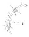
- FIG. 1illustrates an embodiment of device 100 for electrical cable 150 , where electrical cable 150 is configured to couple electrical connector 160 with an electric vehicle charging station and where electrical connector 160 is configured to be coupled with an electric vehicle to permit the electric vehicle charging station to provide electricity to a rechargeable energy storage system of the electric vehicle.
- Device 100is merely exemplary and is not limited to the embodiments presented herein. Device 100 can be employed in many different embodiments or examples not specifically depicted or described herein.
- Device 100comprises receiver assembly 101 comprising hollow space 102 .
- Device 100 and/or receiver assembly 101can be configured to be coupled with electrical cable 150 .
- device 100 and/or receiver assembly 101can be configured to be coupled with electrical cable 150 at hollow space 102 .
- Device 100 and/or receiver assembly 101can comprise both open and closed configurations.
- device 100 and/or receiver assembly 101can be part of electrical cable 150 .
- receiver assembly 101can be referred to as a tubular portion.
- Electrical cable 150comprises electrical cable outer surface 151 .
- Receiver assembly 101can be configured to be coupled with electrical cable 150 at a first cable location 152 .
- Receiver assembly 101can be configured to be coupled with electrical cable 150 by wrapping receiver assembly 101 around at least part of electrical cable outer surface 151 .
- receiver assembly 101can be configured to receive an end of electrical cable 150 and to slide along electrical cable 150 (e.g., when the end of electrical cable 150 is not yet coupled to, or has been decoupled from, electrical connector 160 and/or the electric vehicle charging station) to first cable location 152 to couple with electrical cable 150 .
- receiver assembly 101can comprise multiple pieces configured to couple to each other in order to couple around at least part of electrical cable outer surface 151 at the first cable location 152 .
- receiver assembly 101 and/or the multiple pieces of receiver assembly 101can comprise first piece 104 and second piece 105 opposite first piece 104 .
- First piece 104can be configured to be coupled with second piece 105 , and/or vice versa.
- receiver assembly 101 and/or first piece 104can comprise at least one male pressure fitting
- receiver assembly 101 and/or second piece 105can comprise at least one female pressure fitting configured to receive the at least one male pressure fitting, or vice versa.
- the at least one male pressure fittingcan be configured to be coupled to the at least one female pressure fitting when receiver assembly 101 is coupled with electrical cable 150 by wrapping receiver assembly 101 around at least part of electrical cable outer surface 151 .
- Receiver assembly 101can comprise at least one latching or clasping mechanism configured to couple receiver assembly 101 to itself and/or to couple one or more pieces of receiver assembly 101 together when receiver assembly 101 is coupled with electrical cable 150 by wrapping receiver assembly 101 around at least part of electrical cable outer surface 151 .
- receiver assembly 101can comprise at least one hinge coupling one or more of the multiple pieces of receiver assembly 101 together (e.g., first piece 104 and second piece 105 ).
- first piece 104 and second piece 105can be coupled together at one side by one or more hinges to permit first piece 104 and second piece 105 to pivot at the hinge to wrap around electrical cable outer surface 151 .
- first piece 104 and second piece 105can be coupled at the other side by the one or more pressure fittings and/or the one or more latching or clasping mechanisms.
- the one or more hingescan be replaced with one or more additional pressure fittings (e.g., such that first piece 104 and second piece 105 snap together at both sides) and/or one or more latching/clasping mechanisms to couple together the opposite side of first piece 104 and second piece 105 .
- receiver assembly 101can be configured to be coupled with electrical cable 150 by one or more external fasteners (e.g., tie-wraps, screw clamps, etc.).
- the one or more external fastenerscan be applied to receiver assembly outer surface 106 , as described below, to couple receiver assembly 101 to electrical cable 150 .
- the one or more external fastenerscan be implemented in combination with one of the other manners of coupling describe above to further secure receiver assembly 101 to electrical cable 150 .
- receiver assembly 101can comprise receiver assembly outer surface 106 and/or a receiver assembly inner surface opposite to receiver assembly outer surface 106 .
- the receiver assembly inner surfacecan comprise a liner covering at least part of the receiver assembly inner surface.
- the linercan comprise a material having a coefficient of friction sufficient to inhibit and/or prevent movement (e.g., shifting) of receiver assembly 101 along electrical cable 150 when receiver assembly 101 is coupled with electrical cable 150 .
- receiver assembly outer surface 106can comprise a receiver assembly outer cross-section and/or the receiver assembly inner surface can comprise a receiver assembly inner cross-section.
- the combination of the receiver assembly outer cross-section and the receiver assembly inner cross-sectionform a cross-section of receiver assembly 101 .
- Receiver assembly 101 , the receiver assembly outer cross-section, and/or the receiver assembly inner cross-sectioncan comprise a tubular shape and/or a circular cross-section.
- receiver assembly outer cross-section and/or receiver assembly inner cross-sectioncan comprise any of various other shapes (e.g., a triangle, a square, or other multi-sided polygon, etc.).
- the receiver assembly outer cross-section and the receiver assembly inner cross-sectioncan comprise the same shape, but can also be different shapes.
- the receiver assembly inner cross-sectioncan be the same shape as electrical cable outer surface 151 and/or electrical cable 150 .
- Receiver assembly 101can have a length of approximately 6 inches (15.2 centimeters) to approximately 12 inches (30.5 centimeters) with respect to a longitudinal dimension of electrical cable 150 .
- Receiver assembly 101can have a width larger than circumference, perimeter, or diameter of electrical cable outer surface 151 and/or electrical cable 150 .
- Receiver assembly 101can comprise plastic (e.g., polycarbonate, polyurethane, and/or acrylonitrile butadiene styrene, etc.) and/or metal (aluminum, stainless steel, etc.).
- the plastic and/or metalcan be rigid.
- receiver assembly 101can be covered in plastic and/or rubber.
- the liner of the receiver assembly inner surfacecan comprise the plastic and/or rubber covering receiver assembly 101 , or the liner can be separate and/or over the covering.
- Device 100also comprises one or more gripping mechanisms 103 (e.g., three gripping mechanisms) coupled to receiver assembly 101 .
- gripping mechanism(s) 103comprise multiple gripping mechanisms
- each of gripping mechanisms 103can be similar or identical to each other.
- one or more of gripping mechanisms 103can differ from at least another one of gripping mechanisms 103 .
- gripping mechanisms 103can be referred to as one or more handles (e.g., three handles).
- first piece 104 and second piece 105when receiver assembly 101 comprises two pieces (e.g., first piece 104 and second piece 105 ) and gripping mechanism(s) 103 comprise multiple gripping mechanisms, the first piece (e.g., first piece 104 ) can comprise one of gripping mechanisms 103 , and the second piece (e.g., second piece 105 ) can comprise one or more (e.g. two) of gripping mechanisms 103 , or vice versa.
- each of the three piecescan comprise a single one of the three of gripping mechanisms 103 .
- the first and second pieces of receiver assembly 101can be hingedly coupled together, and the second and third pieces of receiver assembly 101 can be hingedly coupled together.
- receiver assembly 101 and/or the three or more gripping mechanisms 103can be molded, cast, or forged.
- receiver assembly 101comprises multiple pieces
- each of the multiple pieces of receiver assembly 101 and/or the corresponding three or more gripping mechanisms 103can be molded, cast, or forged.
- receiver assembly outer surface 106can comprise one or more receptacles 107 (e.g., three receptacles).
- a first quantity of receptacle(s) 107can be equal to a second quantity of gripping mechanism(s) 103 .
- each one of receptacle(s) 107can be configured to receive any one of gripping mechanism(s) 103 (i.e., gripping mechanism(s) 103 are attachable/detachable from receiver assembly 101 ).
- receptacle(s) 107can comprise one or more channels configured such that each one of gripping mechanism(s) 103 can be slid into a different one of the one or more channels.
- receptacle(s) 107can comprise threading such that each one of gripping mechanism(s) 103 can be screwed into one of receptacle(s) 107 .
- gripping mechanism(s) 103can be integral to receiver assembly 101 such that at least one of gripping mechanism(s) 103 and one piece of receiver assembly 101 form a single piece.
- Gripping mechanism(s) 103can extend radially outward from receiver assembly 101 and/or electrical cable 150 . In some embodiments, gripping mechanism(s) 103 can extend radially outward from receiver assembly 101 and/or receiver assembly outer surface 106 between approximately 3 inches (7.5 centimeters) and approximately 6 inches (15.2 centimeters).
- Gripping mechanism(s) 103can have lengths of approximately 6 inches (15.2 centimeters) to approximately 12 inches (30.5 centimeters) with respect to a longitudinal dimension of electrical cable 150 .
- Gripping mechanism(s) 103can have widths of approximately 0.5 inches (1.2 centimeters) to approximately 1 inch (4.1 centimeters) with respect to a lateral dimension (e.g., circumference, perimeter, diameter, etc.) of electrical cable 150 .
- Each one of gripping mechanism(s) 103can comprise plastic (e.g., polycarbonate, polyurethane, and/or acrylonitrile butadiene styrene, etc.) and/or metal (aluminum, stainless steel, etc.).
- the plastic and/or metalcan be rigid.
- gripping mechanism(s) 103can be covered in plastic and/or rubber.
- the liner of the receiver assembly inner surfacecan comprise the plastic and/or rubber covering gripping mechanism(s) 103 , or the liner can be separate and/or over the covering.
- Each one of gripping mechanism(s) 103can be configured such that a user of the electric vehicle charging station can grasp at least one of gripping mechanism(s) 103 to facilitate movement of electrical cable 150 when electrical cable 150 is located in hollow space 102 .
- Gripping mechanism(s) 103can each comprise an opening sized at least to fit four fingers and/or a palm of a human hand. In some embodiments, at least part of the opening of one or more of gripping mechanism(s) 103 can be molded to conform to a shape of the four fingers and/or the palm of the human hand.
- gripping mechanism(s) 103can be configured to prevent electrical connector 160 from contacting the ground when at least one (e.g., one, two, three, etc.) of gripping mechanism(s) 103 contacts the ground and when the electrical cable is located in hollow space 102 .
- device 100 and/or gripping mechanism(s) 103can absorb at least part of an impact to electrical cable 150 and/or electrical connector 160 to prevent or reduce damage inflicted on electrical cable 150 and/or electrical connector 160 as a result of the impact.
- the impactcould be the result of the user dropping electrical cable 150 and/or electrical connector 160 .
- the impactcould be the result of the electric vehicle or any other vehicle driving over the electrical cable 150 and/or electrical connector 160 .
- device 100 and/or gripping mechanism(s) 103can be configured with one or more crumple zones, similar to the crumple zones in an automobile chassis, to absorb the impact.
- device 100 and/or gripping mechanism(s) 103can inherently absorb the impact where device 100 and/or gripping mechanism(s) 103 comprise a rigid and/or strong material.
- device 100 , receiver assembly 101 , and/or at least one of gripping mechanism(s) 103can comprise a bright color.
- the bright colorcan comprise yellow, orange, red, green, blue, purple, etc., or any fluorescent color
- visibility of the electrical cablecan be improved. Accordingly, the increased visibility can prevent electrical cable 150 from being driven over by a vehicle or tripped over by a user of the vehicle.
- receiver assembly 101 and/or at least one of gripping mechanism(s) 103can be configured to be mounted on the electric vehicle charging station to aid in storing electrical cable 150 and/or electrical connector 160 of the electric vehicle charging station.
- receiver assembly 101(and where applicable, one or more additional receiver assemblies (e.g., receiver assembly 191 , as described below) can be configured to be mounted to and/or stored at a drum-like reel of the electric vehicle charging station, the reel being configured to receive and to store electrical cable 150 , when the reel has received and is storing electrical cable 150 and receiver assembly 101 (and any additional receiver assemblies, as applicable) is coupled to electrical cable 150 .
- electrical cable 150can be spooled around the reel for purposes of storage and/or to keep all or part of electrical cable 150 organized.
- the reelcan comprise at least one receiver assembly receptacle, each receiver assembly receptacle of the at least one receiver assembly receptacle being configured to receive a different one of the one or more receiver assemblies (e.g., receiver assembly 101 , receiver assembly 191 , etc.) of device 100 when the reel is storing electrical cable 150 .
- a quantity of the at least one receiver assemblycan be equal to a quantity of the one or more receiver assemblies.
- the at least one receiver assembly receptaclecan be located and/or positioned at the top of the reel. Where device 100 comprises multiple receiver assemblies, each of the multiple receiver assemblies can be equally spaced apart along electrical cable 150 when coupled to electrical cable 150 , as described in further detail below.
- each of the multiple receiver assembliescan be indexed into its respective receiver assembly receptacle such that each coil or loop of electrical cable 150 is spooled around the reel in approximately equal lengths.
- each receiver assembly of the multiple receiver assembliescan be stored.
- each of the multiple receiver assembliescan be spaced progressively further apart (or closer together) along electrical cable 150 depending on the configuration of the at least one receiver assembly receptacle. For example, if the at least one receiver assembly receptacle comprises multiple receiver assembly receptacles and the receiver assembly receptacles are positioned at different distances from each other with respect to the reel, it may be desirable to space apart the multiple receiver assemblies accordingly, as described above.
- device 100can comprise one or more additional receiver assemblies, where each one of the one or more additional receiver assemblies can comprise one or more (e.g., three) additional gripping mechanisms coupled to each one of the one or more additional receiver assemblies.
- the one or more additional receiver assembliescan be similar or identical to receiver assembly 101 , and/or the additional gripping mechanism(s) can be similar or identical to gripping mechanism(s) 103 .
- device 100can comprise second receiver assembly 191 and one or more (e.g., three) second gripping mechanisms 193 .
- receiver assembly 101When receiver assembly 101 is coupled with electrical cable 150 and when second receiver assembly 191 is coupled with electrical cable 150 , receiver assembly 101 can be coupled with electrical cable 150 at first cable location 152 and second receiver assembly 191 can be coupled with electric cable 150 at second cable location 153 closer to electrical connector 160 than first cable location 152 along the longitudinal dimension of electrical cable 150 .
- receiver assembly 101 and/or first cable location 152can be approximately 6 inches (15.2 centimeters) to approximately 24 inches (61 centimeters) apart from second receiver assembly 191 and/or second cable location 153 .
- each receiver assembly of the multiple assembliesmay be coordinated with its respective receiver assembly receptacle, as described above, to indicate which receiver assembly is associated with that receiver assembly receptacle.
- each receiver assemblymay comprise a different color or some other indicator (e.g., a symbol, a number, a letter, etc.) and each receiver assembly receptacle may comprise a complimentary color or other indicator to that of its respective receiver assembly to clearly indicate which receiver assembly is associated with that receiver assembly receptacle.
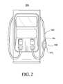
- FIG. 2illustrates an exemplary embodiment of device 100 when a single one of device 100 and/or receiver assembly 101 are coupled to electrical cable 150 while electrical connector 160 and electrical cable 150 are in a stored position at electric vehicle charging station 200 .
- Electric vehicle charging station 200comprises electrical cable 150 , device 100 , and the electrical connector (not shown in FIG. 2 ).
- FIG. 3illustrates the exemplary embodiment of device 100 when device 100 and/or receiver assembly 101 are coupled to electrical cable 150 while electrical connector 160 is coupled with electric vehicle 300 and/or electric vehicle charging station 200 is providing electricity to the rechargeable energy storage system of the electric vehicle.
- FIG. 4illustrates a flow chart for an embodiment of method 400 of providing a device for an electrical cable, where the electrical cable is configured to couple an electrical connector with an electric vehicle charging station and the electrical connector is configured to be coupled with an electric vehicle to permit the electric vehicle charging station to provide electricity to a rechargeable energy storage system of the electric vehicle.
- the devicecan be similar or identical to device 100 ( FIG. 1 ), and the electrical cable can be similar or identical to electrical cable 150 .
- the electric vehicle charging stationcan be similar or identical to electric vehicle charging station 200 ( FIG. 2 ), and the electric vehicle can be similar or identical to electric vehicle 300 ( FIG. 3 ).
- Method 400is merely exemplary and is not limited to the embodiments presented herein.
- Method 400can be employed in many different embodiments or examples not specifically depicted or described herein. In some embodiments, the procedures, the processes, and/or the activities of method 400 can be performed in the order presented. In other embodiments, the procedures, the processes, and/or the activities of the method 400 can be performed in any other suitable order. In still other embodiments, one or more of the procedures, the processes, and/or the activities in method 400 can be combined or skipped.
- Method 400can comprise procedure 401 of providing a receiver assembly configured to be coupled with the electrical cable.
- the receiver assemblycan be similar or identical to receiver assembly 101 ( FIG. 1 ).
- Method 400can comprise procedure 402 of providing one or more gripping mechanisms configured such that a user of the electric vehicle charging station can grasp at least one of the gripping mechanism(s) to facilitate movement of the electrical cable when the receiver assembly is coupled with the electrical cable.
- performing procedure 402can comprise providing three or more gripping mechanisms.
- the gripping mechanism(s)can be similar or identical to gripping mechanism(s) 103 ( FIG. 1 ).
- procedure 401 and procedure 402can be performed and/or can occur simultaneously.
- procedure 401can comprise one of molding, forging, or casting the receiver assembly configured to be coupled with the electrical cable.
- procedure 402can comprise one of molding, forging, or casting the gripping mechanism(s).
- the receiver assembly and the gripping mechanism(s)can be molded, forged, or casted together simultaneously or at least part of the receiver assembly, and one or more of the gripping mechanism(s) can be molded, forged, or casted together, as described above with respect to device 100 ( FIG. 1 ) when the receiver assembly comprises multiple pieces.
- Method 400can comprise procedure 403 of coupling each one of the gripping mechanism(s) (e.g., three gripping mechanisms) with the receiver assembly (e.g., where the receiver assembly and gripping mechanism(s) are separate pieces).
- procedure 403can comprise coupling each one of the gripping mechanism(s) with a different one of one or more receptacles (e.g., three receptacles) of a receiver assembly outer surface of the receiver assembly.
- the receptacle(s)can be similar or identical to receptacle(s) 107 ( FIG. 1 ), and/or the receiver assembly outer surface can be similar or identical to receiver assembly outer surface 151 ( FIG. 1 ).
- each one of the receptacle(s)can comprise a channel.
- coupling each one of the gripping mechanism(s) with the different one of the receptacle(s) of the receiver assembly outer surfacecomprises sliding each one of the gripping mechanism(s) into the different one of each one of the receptacle(s).
- procedure 403can be omitted.
- Method 400can comprise procedure 404 of coupling the receiver assembly with the electrical cable.
- Procedure 404 of coupling the receiver assembly with the electrical cablecan be performed similarly or identically to any of the approaches described above with respect to device 100 ( FIG. 1 ).
- FIG. 5illustrates an exemplary embodiment of procedure 404 , according to the embodiment of method 400 .
- procedure 404can comprise process 501 of wrapping the receiver assembly around at least part of the electrical cable outer surface of the electrical cable.
- Procedure 400can further comprise process 502 of coupling a first portion of the receiver assembly to a second portion of the receiver assembly opposite the first portion of the receiver assembly.
- process 502comprises coupling at least one male pressure fitting at the first portion of the receiver assembly to at least one female pressure fitting at the second portion of the receiver assembly, where the at least one female pressure fitting is configured to receive the at least one male pressure fitting.
- device 100can be used with cables that are not part of an electric vehicle charging station, with other types of electrical cables, and with other types of non-electrical cables.
- embodiments and limitations disclosed hereinare not dedicated to the public under the doctrine of dedication if the embodiments and/or limitations: (1) are not expressly claimed in the claims; and (2) are or are potentially equivalents of express elements and/or limitations in the claims under the doctrine of equivalents.
Landscapes
- Engineering & Computer Science (AREA)
- Power Engineering (AREA)
- Transportation (AREA)
- Mechanical Engineering (AREA)
- Charge And Discharge Circuits For Batteries Or The Like (AREA)
Abstract
Description
Claims (25)
Priority Applications (1)
| Application Number | Priority Date | Filing Date | Title |
|---|---|---|---|
| US13/442,684US8710372B2 (en) | 2010-07-23 | 2012-04-09 | Device to facilitate moving an electrical cable of an electric vehicle charging station and method of providing the same |
Applications Claiming Priority (9)
| Application Number | Priority Date | Filing Date | Title |
|---|---|---|---|
| US36731710P | 2010-07-23 | 2010-07-23 | |
| US36732110P | 2010-07-23 | 2010-07-23 | |
| US36733710P | 2010-07-23 | 2010-07-23 | |
| US36731610P | 2010-07-23 | 2010-07-23 | |
| PCT/US2011/034667WO2012012008A2 (en) | 2010-07-23 | 2011-04-29 | System for advertising and communicating at a vehicle charging station and method of using the same |
| US201161489187P | 2011-05-23 | 2011-05-23 | |
| PCT/US2011/037587WO2012012021A1 (en) | 2010-07-23 | 2011-05-23 | System for interfacing with an electric vehicle charging station and method of using and providing the same |
| PCT/US2012/030000WO2012148597A1 (en) | 2011-04-29 | 2012-03-21 | Device to facilitate moving an electrical cable of an electric vehicle charging station and method of providing the same |
| US13/442,684US8710372B2 (en) | 2010-07-23 | 2012-04-09 | Device to facilitate moving an electrical cable of an electric vehicle charging station and method of providing the same |
Related Parent Applications (1)
| Application Number | Title | Priority Date | Filing Date |
|---|---|---|---|
| PCT/US2012/030000ContinuationWO2012148597A1 (en) | 2010-07-23 | 2012-03-21 | Device to facilitate moving an electrical cable of an electric vehicle charging station and method of providing the same |
Publications (2)
| Publication Number | Publication Date |
|---|---|
| US20120193929A1 US20120193929A1 (en) | 2012-08-02 |
| US8710372B2true US8710372B2 (en) | 2014-04-29 |
Family
ID=47072682
Family Applications (1)
| Application Number | Title | Priority Date | Filing Date |
|---|---|---|---|
| US13/442,684Expired - Fee RelatedUS8710372B2 (en) | 2010-07-23 | 2012-04-09 | Device to facilitate moving an electrical cable of an electric vehicle charging station and method of providing the same |
Country Status (2)
| Country | Link |
|---|---|
| US (1) | US8710372B2 (en) |
| WO (1) | WO2012148597A1 (en) |
Cited By (11)
| Publication number | Priority date | Publication date | Assignee | Title |
|---|---|---|---|---|
| US20140244090A1 (en)* | 2011-10-03 | 2014-08-28 | Husqvarna Ab | Battery Powered Vehicle with Immobilizing Charger Plug |
| US8841881B2 (en) | 2010-06-02 | 2014-09-23 | Bryan Marc Failing | Energy transfer with vehicles |
| USD736716S1 (en)* | 2013-07-22 | 2015-08-18 | Evatran Group, Inc. | Control panel for a motor vehicle charging station |
| US20170282736A1 (en)* | 2016-04-01 | 2017-10-05 | Ijuze Corporation Pte Ltd. | Automated system for managing and providing a network of charging stations |
| DE102018100830A1 (en) | 2018-01-16 | 2019-07-18 | Dr. Ing. H.C. F. Porsche Aktiengesellschaft | Charging cable for a charging station and charging station with such a charging cable |
| DE102018100826A1 (en) | 2018-01-16 | 2019-07-18 | Dr. Ing. H.C. F. Porsche Aktiengesellschaft | Charging cable and method for charging an electric car |
| US10515742B1 (en) | 2018-05-31 | 2019-12-24 | General Electric Company | Power cable and system for delivering electrical power |
| USD892725S1 (en) | 2014-12-31 | 2020-08-11 | Chargepoint, Inc. | Electric vehicle charging station |
| US20210080282A1 (en)* | 2017-04-03 | 2021-03-18 | Power Hero Corp. | Universal automated system for identifying, registering and verifying the existence, location and characteristics of electric and other power outlets by random users and for retrieval and utilization of such parametric data and outlets by all users |
| US11724614B2 (en) | 2021-04-08 | 2023-08-15 | AddÉnergie Technologies Inc. | Electrical break-away system for electric vehicle charging station |
| US12351059B1 (en) | 2024-06-28 | 2025-07-08 | Swtch Energy Inc. | Dynamic energy management for EV charging with real-time allocation using predictive control and coordination of facility energy demands including HVAC systems |
Families Citing this family (7)
| Publication number | Priority date | Publication date | Assignee | Title |
|---|---|---|---|---|
| JP5713028B2 (en)* | 2011-02-03 | 2015-05-07 | トヨタ自動車株式会社 | Vehicle-mounted cable and vehicle |
| JP5392327B2 (en)* | 2011-09-11 | 2014-01-22 | 日産自動車株式会社 | Intermediate gripping tool for charging cable |
| NO340964B1 (en)* | 2016-02-17 | 2017-07-31 | Norfax | A charging station for recharging eletrical vehicles |
| JP7415326B2 (en)* | 2019-03-15 | 2024-01-17 | 株式会社Gsユアサ | cable gripper |
| US12119146B2 (en)* | 2019-06-11 | 2024-10-15 | The Board Of Regents Of The University Of Oklahoma | Coaxial phase change material heat sink for electric charging cable |
| KR102492458B1 (en) | 2020-04-29 | 2023-01-30 | 주식회사 남전사 | Electric vehicle charger cable capable of AC / DC metering |
| DE202022102059U1 (en) | 2022-04-17 | 2023-07-19 | SMA Solar Technology AG | Charging station for charging an electrical energy store in a motor vehicle with a cable holder |
Citations (127)
| Publication number | Priority date | Publication date | Assignee | Title |
|---|---|---|---|---|
| US4532418A (en) | 1982-08-30 | 1985-07-30 | The Detroit Edison Company | Microprocessor electric vehicle charging and parking meter system structure and method |
| US5057762A (en) | 1990-07-30 | 1991-10-15 | Motorola, Inc. | System for determining battery charge states and charging sequence for a battery charger |
| EP0533317A2 (en) | 1991-05-31 | 1993-03-24 | Honda Giken Kogyo Kabushiki Kaisha | Battery cell for electric vehicle |
| US5202617A (en) | 1991-10-15 | 1993-04-13 | Norvik Technologies Inc. | Charging station for electric vehicles |
| US5327066A (en) | 1993-05-25 | 1994-07-05 | Intellectual Property Development Associates Of Connecticut, Inc. | Methods and apparatus for dispensing a consumable energy source to a vehicle |
| US5341083A (en) | 1991-09-27 | 1994-08-23 | Electric Power Research Institute, Inc. | Contactless battery charging system |
| JPH06290836A (en)* | 1993-03-31 | 1994-10-18 | Sumitomo Wiring Syst Ltd | Charging connector for electric vehicle |
| US5536173A (en)* | 1993-07-22 | 1996-07-16 | Sumitomo Wiring Systems, Ltd. | Charge connector for electric vehicles |
| US5548200A (en) | 1994-07-06 | 1996-08-20 | Norvik Traction Inc. | Universal charging station and method for charging electric vehicle batteries |
| US5594318A (en) | 1995-04-10 | 1997-01-14 | Norvik Traction Inc. | Traction battery charging with inductive coupling |
| US5705910A (en) | 1995-02-15 | 1998-01-06 | Fujitsu Limited | Electric charge/discharge control device and electric charge/discharge control method in a system using the same device |
| US6029072A (en) | 1996-01-25 | 2000-02-22 | Oki Telecom, Inc. | Portable telephone with terminal mode facility |
| US6225153B1 (en)* | 1999-03-24 | 2001-05-01 | Daimlerchrysler Corporation | Universal charge port connector for electric vehicles |
| US6373380B1 (en) | 2000-01-10 | 2002-04-16 | Ford Motor Company | Communication method and system for configuring electric powered vehicles |
| US6471268B1 (en)* | 1999-04-20 | 2002-10-29 | Peter John Stenstrom | Device for displacing a pipe etc |
| JP2004096973A (en) | 2002-09-04 | 2004-03-25 | Kenwood Corp | Data acquisition system |
| US6725104B2 (en) | 2001-09-21 | 2004-04-20 | Siemens Aktiengesellschaft | Method and apparatus for E-mail based communication with automated facilities and devices |
| EP1458039A2 (en) | 2003-03-10 | 2004-09-15 | Nissan Motor Co., Ltd. | Sealed nickel-metal hybride storage cells and hybrid electric vehicle having the storage cells |
| KR100460879B1 (en) | 2002-06-19 | 2004-12-09 | 현대자동차주식회사 | Charge controlling method of electric vehicle |
| JP2006074868A (en) | 2004-08-31 | 2006-03-16 | Fuji Heavy Ind Ltd | Battery charging system of electric automobile |
| US20060089844A1 (en) | 2004-10-26 | 2006-04-27 | Aerovironment, Inc., A California Corporation | Dynamic replenisher management |
| US7045989B2 (en) | 2001-04-18 | 2006-05-16 | Makita Corporation | Methods and apparatus for managing a plurality of charging devices via a network |
| JP2006178259A (en) | 2004-12-24 | 2006-07-06 | Seiko Epson Corp | Advertisement information display system, advertisement device, communication device, and advertisement information display method |
| US20060158037A1 (en) | 2005-01-18 | 2006-07-20 | Danley Douglas R | Fully integrated power storage and supply appliance with power uploading capability |
| US7116079B2 (en) | 2004-02-27 | 2006-10-03 | Research In Motion Limited | Methods and apparatus for simultaneously charging multiple rechargable batteries |
| JP2006287705A (en) | 2005-04-01 | 2006-10-19 | Matsushita Electric Ind Co Ltd | COMMUNICATION SYSTEM, VEHICLE INFORMATION COMMUNICATION DEVICE, AND INDOOR INFORMATION PROCESSING DEVICE |
| US7135836B2 (en) | 2003-03-28 | 2006-11-14 | Power Designers, Llc | Modular and reconfigurable rapid battery charger |
| US20060276938A1 (en) | 2005-06-06 | 2006-12-07 | Equinox Energy Solutions, Inc. | Optimized energy management system |
| JP2007006573A (en) | 2005-06-22 | 2007-01-11 | Hitachi Ltd | Power supply system |
| US7196494B2 (en) | 2003-10-17 | 2007-03-27 | Xantrex International | Method and apparatus for charging batteries in a system of batteries |
| US7253586B2 (en) | 2004-03-11 | 2007-08-07 | Lenovo (Singapore) Pte. Ltd. | Intelligent multiple battery charging station |
| US20070203860A1 (en) | 2006-02-24 | 2007-08-30 | Gridpoint, Inc. | Energy budget manager |
| US20070271006A1 (en) | 2006-05-18 | 2007-11-22 | Gridpoint, Inc. | Modular energy control system |
| US20080039989A1 (en) | 2006-08-10 | 2008-02-14 | V2 Green, Inc. | User Interface and User Control in a Power Aggregation System for Distributed Electric Resources |
| US20080040296A1 (en) | 2006-08-10 | 2008-02-14 | V2 Green Inc. | Electric Resource Power Meter in a Power Aggregation System for Distributed Electric Resources |
| US20080040263A1 (en) | 2006-08-10 | 2008-02-14 | V2 Green, Inc. | Business Methods in a Power Aggregation System for Distributed Electric Resources |
| US20080039980A1 (en) | 2006-08-10 | 2008-02-14 | V2 Green Inc. | Scheduling and Control in a Power Aggregation System for Distributed Electric Resources |
| US20080039979A1 (en) | 2006-08-10 | 2008-02-14 | V2 Green Inc. | Smart Islanding and Power Backup in a Power Aggregation System for Distributed Electric Resources |
| US20080040479A1 (en) | 2006-08-10 | 2008-02-14 | V2 Green Inc. | Connection Locator in a Power Aggregation System for Distributed Electric Resources |
| US20080040295A1 (en) | 2006-08-10 | 2008-02-14 | V2 Green, Inc. | Power Aggregation System for Distributed Electric Resources |
| US20080040223A1 (en) | 2006-08-10 | 2008-02-14 | V2 Green Inc. | Electric Resource Module in a Power Aggregation System for Distributed Electric Resources |
| US20080052145A1 (en) | 2006-08-10 | 2008-02-28 | V2 Green, Inc. | Power Aggregation System for Distributed Electric Resources |
| JP2008083022A (en) | 2006-08-30 | 2008-04-10 | Toyota Motor Corp | Power storage device deterioration evaluation system, vehicle, power storage device deterioration evaluation method, and computer-readable recording medium storing a program for causing a computer to execute the deterioration evaluation method |
| US7358701B2 (en) | 2003-02-07 | 2008-04-15 | Field Robert B | Method and system for modeling energy transfer |
| KR100824073B1 (en) | 2006-03-22 | 2008-04-21 | 호진형 | Vehicle linkage management service system and its operation method |
| US20080114499A1 (en) | 2006-11-09 | 2008-05-15 | Gridpoint, Inc. | Energy arbitrage by load shifting |
| US7376631B2 (en) | 2005-05-26 | 2008-05-20 | International Business Machines Corporation | Method, apparatus and computer program product for reporting energy consumption |
| US20080136371A1 (en) | 2006-12-06 | 2008-06-12 | Sehat Sutardja | Plug-in vehicle |
| US20080167756A1 (en) | 2007-01-03 | 2008-07-10 | Gridpoint, Inc. | Utility console for controlling energy resources |
| US7405660B2 (en) | 2005-03-24 | 2008-07-29 | Impinj, Inc. | Error recovery in RFID reader systems |
| US20080203973A1 (en) | 2007-02-27 | 2008-08-28 | Gale Allan R | Interactive battery charger for electric vehicle |
| US20080228533A1 (en) | 2007-03-01 | 2008-09-18 | Zipcar, Inc. | Multi-tiered fleet management cache |
| US20080249965A1 (en) | 2007-03-14 | 2008-10-09 | V2Green, Inc. | System and Apparatus for Collecting and Distributing Voluntary Environmental Impact Offset Payments on Fuel Purchases at Point of Sale |
| US7444192B2 (en) | 2004-10-26 | 2008-10-28 | Aerovironment, Inc. | Reactive replenishable device management |
| US20080281663A1 (en) | 2007-05-09 | 2008-11-13 | Gridpoint, Inc. | Method and system for scheduling the discharge of distributed power storage devices and for levelizing dispatch participation |
| US20080312782A1 (en) | 2007-06-15 | 2008-12-18 | Gene Berdichevsky | Electric vehicle communication interface |
| US20090018706A1 (en) | 2005-11-25 | 2009-01-15 | Lupu Wittner | Flexible electric load management system and method therefore |
| US20090024255A1 (en) | 2007-07-17 | 2009-01-22 | Gridpoint, Inc. | Utility interactive inverter with var dispatch capabilities |
| US20090024545A1 (en) | 2007-07-17 | 2009-01-22 | Gridpoint, Inc. | Method and system for measurement and control of individual circuits |
| US20090030712A1 (en) | 2007-07-26 | 2009-01-29 | Bradley D. Bogolea | System and method for transferring electrical power between grid and vehicle |
| US20090043520A1 (en) | 2006-08-10 | 2009-02-12 | V2Green, Inc. | User Interface and User Control in a Power Aggregation System for Distributed Electric Resources |
| US20090040029A1 (en) | 2006-08-10 | 2009-02-12 | V2Green, Inc. | Transceiver and charging component for a power aggregation system |
| US20090043519A1 (en) | 2006-08-10 | 2009-02-12 | V2Green, Inc. | Electric Resource Power Meter in a Power Aggregation System for Distributed Electric Resources |
| US20090063680A1 (en) | 2006-08-10 | 2009-03-05 | V2Green, Inc. | Connection Locator in a Power Aggregation System for Distributed Electric Resources |
| US20090066287A1 (en) | 2006-08-10 | 2009-03-12 | V2Green, Inc. | Business Methods in a Power Aggregation System for Distributed Electric Resources |
| US20090077397A1 (en) | 2007-09-13 | 2009-03-19 | Gridpoint, Inc. | User interface for demand side energy management |
| US20090082957A1 (en) | 2007-09-20 | 2009-03-26 | Shai Agassi | Electric Vehicle Network |
| US20090088907A1 (en) | 2007-10-01 | 2009-04-02 | Gridpoint, Inc. | Modular electrical grid interface device |
| US20090091291A1 (en) | 2007-10-04 | 2009-04-09 | Gm Global Technology Operations, Inc. | Power grid load management for plug-in vehicles |
| US20090140698A1 (en) | 2007-06-15 | 2009-06-04 | Tesla Motors, Inc. | Multi-mode charging system for an electric vehicle |
| US7546214B2 (en) | 2006-09-28 | 2009-06-09 | General Electric Company | System for power sub-metering |
| JP2009141991A (en) | 2007-12-03 | 2009-06-25 | Toyota Motor Corp | Electric vehicle charging system |
| US20090177580A1 (en) | 2008-01-07 | 2009-07-09 | Lowenthal Richard W | Collection of electric vehicle power consumption tax |
| US20090210357A1 (en) | 2007-10-04 | 2009-08-20 | General Motors Corporation | Remote power usage management for plug-in vehicles |
| US20090228388A1 (en) | 2008-03-07 | 2009-09-10 | Gridpoint, Inc. | System and method for automated trading of electrical consumption |
| US7595607B2 (en) | 2005-12-20 | 2009-09-29 | General Electric Company | Battery charging system and methods |
| US20090259603A1 (en) | 2008-04-10 | 2009-10-15 | Juice Technologies, Inc. | Mobile intelligent metering and charging system for charging uniquely identifiable chargeable vehicle destinations and method for employing same |
| US20090313098A1 (en) | 2008-06-16 | 2009-12-17 | International Business Machines Corporation | Network Based Energy Preference Service for Managing Electric Vehicle Charging Preferences |
| US20100006356A1 (en) | 2008-06-30 | 2010-01-14 | Dave Earl Curry | Electric Vehicle Charging Methods, Battery Charging Methods, Electric Vehicle Charging Systems, Energy Device Control Apparatuses, and Electric Vehicles |
| US7688022B2 (en) | 2006-02-17 | 2010-03-30 | Lear Corporation | Energy management system for a vehicle |
| KR20100035152A (en) | 2010-03-15 | 2010-04-02 | 신이균 | Battery charging apparatus for electric vehicle |
| US20100094496A1 (en) | 2008-09-19 | 2010-04-15 | Barak Hershkovitz | System and Method for Operating an Electric Vehicle |
| US20100100342A1 (en) | 2007-09-05 | 2010-04-22 | Consolidated Edison Company Of New York, Inc. | Metering system and method of operation |
| WO2010047902A2 (en) | 2008-10-24 | 2010-04-29 | The Boeing Company | Intelligent energy management architecture |
| JP2010098793A (en) | 2008-10-14 | 2010-04-30 | Osaka Gas Co Ltd | Power demand and supply system |
| JP2010110044A (en) | 2008-10-28 | 2010-05-13 | Shikoku Electric Power Co Inc | Charging equipment for electric vehicles |
| US7719232B2 (en) | 2007-07-18 | 2010-05-18 | Tesla Motors, Inc. | Method for battery charging based on cost and life |
| JP2010114988A (en) | 2008-11-05 | 2010-05-20 | Denso Corp | Vehicle charger device and vehicle charging system |
| US20100134067A1 (en) | 2009-07-23 | 2010-06-03 | David Baxter | Electrical circuit sharing for electric vehicle charging stations |
| US20100138178A1 (en) | 2009-04-08 | 2010-06-03 | Tesla Motors, Inc. | Battery capacity estimating method and apparatus |
| WO2010060370A1 (en) | 2008-11-25 | 2010-06-03 | Byd Company Limited | Charging device for electrically drivable vehicle |
| EP2199143A1 (en) | 2008-12-22 | 2010-06-23 | General Electric Company | System and method for electric vehicle charging and billing using a wireless vehicle communication service |
| US20100161518A1 (en) | 2008-12-22 | 2010-06-24 | Nathan Bowman Littrell | Electricity storage controller with integrated electricity meter and methods for using same |
| US20100161517A1 (en) | 2008-12-22 | 2010-06-24 | Nathan Bowman Littrell | Systems and methods for electricity metering for vehicular applications |
| US20100164439A1 (en) | 2008-12-25 | 2010-07-01 | Omron Corporation | Charging control device, method, and program |
| US7756507B2 (en) | 2001-10-24 | 2010-07-13 | Siemens Aktiengesellschaft | Method and device for authenticated access of a station to local data networks in particular radio data networks |
| US20100188043A1 (en) | 2009-01-29 | 2010-07-29 | Tesla Motors, Inc. | System for optimizing battery pack cut-off voltage |
| US20100211643A1 (en) | 2009-02-17 | 2010-08-19 | Richard Lowenthal | Transmitting Notification Messages for an Electric Vehicle Charging Network |
| US20100211340A1 (en) | 2009-02-17 | 2010-08-19 | Richard Lowenthal | System and method for managing electric vehicles |
| US20100207588A1 (en) | 2009-02-17 | 2010-08-19 | Richard Lowenthal | Detecting and Responding to Unexpected Electric Vehicle Charging Disconnections |
| US20100238596A1 (en) | 2006-06-29 | 2010-09-23 | Computerized Electricity Systems Ltd. | Detecting sub-system |
| US7804274B2 (en) | 2008-07-21 | 2010-09-28 | Coulomb Technologies, Inc. | Vehicle charging station having a dual position locking door |
| US20100259213A1 (en) | 2009-04-08 | 2010-10-14 | Maharaj Ashwin C | Portable device charging station with advertising display |
| WO2010120551A1 (en) | 2009-03-31 | 2010-10-21 | Gridpoint, Inc. | Electric vehicle power management systems |
| WO2010132495A2 (en) | 2009-05-15 | 2010-11-18 | Battelle Memorial Institute | Battery charging control methods, electric vehicle charging methods, battery charging apparatuses and rechargeable battery systems |
| US20100295508A1 (en) | 2009-05-22 | 2010-11-25 | Lear Corporation | Apparatus and method for balancing the transfer of electrical energy from an external power source to a vehicle |
| US20100301809A1 (en) | 2009-06-02 | 2010-12-02 | Harjinder Bhade | Overcurrent and ground fault protection in a networked charging station for electric vehicles |
| US20100315089A1 (en) | 2009-06-16 | 2010-12-16 | Lester Electrical | System and method for battery charger self test and diagnostic means |
| US20100315197A1 (en) | 2009-07-23 | 2010-12-16 | James Solomon | Authorization in a networked electric vehicle charging system |
| US20100332373A1 (en) | 2009-02-26 | 2010-12-30 | Jason Crabtree | System and method for participation in energy-related markets |
| US20110015799A1 (en) | 2009-07-17 | 2011-01-20 | Gridpoint, Inc. | Smart charging value and guarantee application |
| US20110029157A1 (en) | 2009-07-30 | 2011-02-03 | Aerovironment, Inc. | Remote Rechargeable Monitoring System and Method |
| US20110029144A1 (en) | 2009-07-28 | 2011-02-03 | Michael Muller | Plug-In Electric Vehicle Supply Equipment |
| US20110037429A1 (en) | 2009-08-11 | 2011-02-17 | Siemens Industry, Inc. | Electrical distribution system recharging station for electric vehicles |
| US20110043163A1 (en) | 2009-08-24 | 2011-02-24 | Access Business Group International Llc | Wireless power distribution and control system |
| US20110050168A1 (en) | 2009-08-27 | 2011-03-03 | Electronics And Telecommunications Research Institute | Charge control method for vehicle and device thereof |
| US20110055037A1 (en) | 2009-08-11 | 2011-03-03 | Larry Hayashigawa | Stored energy and charging appliance |
| US20110061014A1 (en) | 2008-02-01 | 2011-03-10 | Energyhub | Interfacing to resource consumption management devices |
| WO2011032104A1 (en) | 2009-09-14 | 2011-03-17 | Better Place GmbH | Flexible connector |
| US20110072112A1 (en) | 2009-09-23 | 2011-03-24 | David S. Kaplan | Electric vehicle data-application connector system |
| US20110106327A1 (en) | 2009-11-05 | 2011-05-05 | General Electric Company | Energy optimization method |
| US20110106329A1 (en) | 2009-11-03 | 2011-05-05 | GRIDbot, LLC | Methods and apparatus for charging station with sms user interface |
| US20110121791A1 (en) | 2009-11-23 | 2011-05-26 | International Business Machines Corporation | Charging management method and system |
| US7952319B2 (en) | 2008-01-07 | 2011-05-31 | Coulomb Technologies, Inc. | Street light mounted network-controlled charge transfer device for electric vehicles |
| US7956570B2 (en) | 2008-01-07 | 2011-06-07 | Coulomb Technologies, Inc. | Network-controlled charging system for electric vehicles |
| US20110169447A1 (en) | 2010-01-11 | 2011-07-14 | Leviton Manufacturing Co., Inc. | Electric vehicle supply equipment |
| US20110202195A1 (en) | 2010-02-15 | 2011-08-18 | General Electric Company | Low cost home energy manager adaptor |
Family Cites Families (1)
| Publication number | Priority date | Publication date | Assignee | Title |
|---|---|---|---|---|
| JPH10117405A (en)* | 1996-10-11 | 1998-05-06 | Sumitomo Wiring Syst Ltd | Electric vehicle charging connector holder |
- 2012
- 2012-03-21WOPCT/US2012/030000patent/WO2012148597A1/enactiveApplication Filing
- 2012-04-09USUS13/442,684patent/US8710372B2/ennot_activeExpired - Fee Related
Patent Citations (167)
| Publication number | Priority date | Publication date | Assignee | Title |
|---|---|---|---|---|
| US4532418A (en) | 1982-08-30 | 1985-07-30 | The Detroit Edison Company | Microprocessor electric vehicle charging and parking meter system structure and method |
| US5057762A (en) | 1990-07-30 | 1991-10-15 | Motorola, Inc. | System for determining battery charge states and charging sequence for a battery charger |
| EP0533317A2 (en) | 1991-05-31 | 1993-03-24 | Honda Giken Kogyo Kabushiki Kaisha | Battery cell for electric vehicle |
| US5341083A (en) | 1991-09-27 | 1994-08-23 | Electric Power Research Institute, Inc. | Contactless battery charging system |
| JP3263075B2 (en) | 1991-10-15 | 2002-03-04 | ノーヴィック トラクション インコーポレイテッド | Charging station for electric transport |
| US5202617A (en) | 1991-10-15 | 1993-04-13 | Norvik Technologies Inc. | Charging station for electric vehicles |
| JPH06290836A (en)* | 1993-03-31 | 1994-10-18 | Sumitomo Wiring Syst Ltd | Charging connector for electric vehicle |
| US5327066A (en) | 1993-05-25 | 1994-07-05 | Intellectual Property Development Associates Of Connecticut, Inc. | Methods and apparatus for dispensing a consumable energy source to a vehicle |
| US5536173A (en)* | 1993-07-22 | 1996-07-16 | Sumitomo Wiring Systems, Ltd. | Charge connector for electric vehicles |
| US5548200A (en) | 1994-07-06 | 1996-08-20 | Norvik Traction Inc. | Universal charging station and method for charging electric vehicle batteries |
| US5705910A (en) | 1995-02-15 | 1998-01-06 | Fujitsu Limited | Electric charge/discharge control device and electric charge/discharge control method in a system using the same device |
| US5594318A (en) | 1995-04-10 | 1997-01-14 | Norvik Traction Inc. | Traction battery charging with inductive coupling |
| US6029072A (en) | 1996-01-25 | 2000-02-22 | Oki Telecom, Inc. | Portable telephone with terminal mode facility |
| US6225153B1 (en)* | 1999-03-24 | 2001-05-01 | Daimlerchrysler Corporation | Universal charge port connector for electric vehicles |
| US6471268B1 (en)* | 1999-04-20 | 2002-10-29 | Peter John Stenstrom | Device for displacing a pipe etc |
| US6373380B1 (en) | 2000-01-10 | 2002-04-16 | Ford Motor Company | Communication method and system for configuring electric powered vehicles |
| US7045989B2 (en) | 2001-04-18 | 2006-05-16 | Makita Corporation | Methods and apparatus for managing a plurality of charging devices via a network |
| US6725104B2 (en) | 2001-09-21 | 2004-04-20 | Siemens Aktiengesellschaft | Method and apparatus for E-mail based communication with automated facilities and devices |
| US7756507B2 (en) | 2001-10-24 | 2010-07-13 | Siemens Aktiengesellschaft | Method and device for authenticated access of a station to local data networks in particular radio data networks |
| KR100460879B1 (en) | 2002-06-19 | 2004-12-09 | 현대자동차주식회사 | Charge controlling method of electric vehicle |
| JP2004096973A (en) | 2002-09-04 | 2004-03-25 | Kenwood Corp | Data acquisition system |
| US7358701B2 (en) | 2003-02-07 | 2008-04-15 | Field Robert B | Method and system for modeling energy transfer |
| EP1458039A2 (en) | 2003-03-10 | 2004-09-15 | Nissan Motor Co., Ltd. | Sealed nickel-metal hybride storage cells and hybrid electric vehicle having the storage cells |
| EP1458039A3 (en) | 2003-03-10 | 2010-02-03 | Nissan Motor Co., Ltd. | Sealed nickel-metal hybride storage cells and hybrid electric vehicle having the storage cells |
| US7135836B2 (en) | 2003-03-28 | 2006-11-14 | Power Designers, Llc | Modular and reconfigurable rapid battery charger |
| US7196494B2 (en) | 2003-10-17 | 2007-03-27 | Xantrex International | Method and apparatus for charging batteries in a system of batteries |
| US7116079B2 (en) | 2004-02-27 | 2006-10-03 | Research In Motion Limited | Methods and apparatus for simultaneously charging multiple rechargable batteries |
| US7253586B2 (en) | 2004-03-11 | 2007-08-07 | Lenovo (Singapore) Pte. Ltd. | Intelligent multiple battery charging station |
| JP2006074868A (en) | 2004-08-31 | 2006-03-16 | Fuji Heavy Ind Ltd | Battery charging system of electric automobile |
| US20090024232A1 (en) | 2004-10-26 | 2009-01-22 | Aerovironment, Inc. | Reactive Replenishable Device Management |
| US20060089844A1 (en) | 2004-10-26 | 2006-04-27 | Aerovironment, Inc., A California Corporation | Dynamic replenisher management |
| US7444192B2 (en) | 2004-10-26 | 2008-10-28 | Aerovironment, Inc. | Reactive replenishable device management |
| US20100332076A1 (en) | 2004-10-26 | 2010-12-30 | Aerovironment, Inc. | Reactive replenishable device management |
| JP2006178259A (en) | 2004-12-24 | 2006-07-06 | Seiko Epson Corp | Advertisement information display system, advertisement device, communication device, and advertisement information display method |
| US20060158037A1 (en) | 2005-01-18 | 2006-07-20 | Danley Douglas R | Fully integrated power storage and supply appliance with power uploading capability |
| US7405660B2 (en) | 2005-03-24 | 2008-07-29 | Impinj, Inc. | Error recovery in RFID reader systems |
| JP2006287705A (en) | 2005-04-01 | 2006-10-19 | Matsushita Electric Ind Co Ltd | COMMUNICATION SYSTEM, VEHICLE INFORMATION COMMUNICATION DEVICE, AND INDOOR INFORMATION PROCESSING DEVICE |
| US7376631B2 (en) | 2005-05-26 | 2008-05-20 | International Business Machines Corporation | Method, apparatus and computer program product for reporting energy consumption |
| US7783390B2 (en) | 2005-06-06 | 2010-08-24 | Gridpoint, Inc. | Method for deferring demand for electrical energy |
| US20060276938A1 (en) | 2005-06-06 | 2006-12-07 | Equinox Energy Solutions, Inc. | Optimized energy management system |
| US20070276547A1 (en) | 2005-06-06 | 2007-11-29 | Gridpoint, Inc. | Optimized Energy Management System |
| US7274975B2 (en) | 2005-06-06 | 2007-09-25 | Gridpoint, Inc. | Optimized energy management system |
| JP2007006573A (en) | 2005-06-22 | 2007-01-11 | Hitachi Ltd | Power supply system |
| US20090018706A1 (en) | 2005-11-25 | 2009-01-15 | Lupu Wittner | Flexible electric load management system and method therefore |
| US7595607B2 (en) | 2005-12-20 | 2009-09-29 | General Electric Company | Battery charging system and methods |
| US7688022B2 (en) | 2006-02-17 | 2010-03-30 | Lear Corporation | Energy management system for a vehicle |
| US20070203860A1 (en) | 2006-02-24 | 2007-08-30 | Gridpoint, Inc. | Energy budget manager |
| KR100824073B1 (en) | 2006-03-22 | 2008-04-21 | 호진형 | Vehicle linkage management service system and its operation method |
| US20070271006A1 (en) | 2006-05-18 | 2007-11-22 | Gridpoint, Inc. | Modular energy control system |
| US20100238596A1 (en) | 2006-06-29 | 2010-09-23 | Computerized Electricity Systems Ltd. | Detecting sub-system |
| US20080039989A1 (en) | 2006-08-10 | 2008-02-14 | V2 Green, Inc. | User Interface and User Control in a Power Aggregation System for Distributed Electric Resources |
| US20080040295A1 (en) | 2006-08-10 | 2008-02-14 | V2 Green, Inc. | Power Aggregation System for Distributed Electric Resources |
| US20080040479A1 (en) | 2006-08-10 | 2008-02-14 | V2 Green Inc. | Connection Locator in a Power Aggregation System for Distributed Electric Resources |
| US20080040223A1 (en) | 2006-08-10 | 2008-02-14 | V2 Green Inc. | Electric Resource Module in a Power Aggregation System for Distributed Electric Resources |
| US20090200988A1 (en) | 2006-08-10 | 2009-08-13 | V2Green, Inc. | Power Aggregation System for Distributed Electric Resources |
| US7747739B2 (en) | 2006-08-10 | 2010-06-29 | Gridpoint, Inc. | Connection locator in a power aggregation system for distributed electric resources |
| US20080039979A1 (en) | 2006-08-10 | 2008-02-14 | V2 Green Inc. | Smart Islanding and Power Backup in a Power Aggregation System for Distributed Electric Resources |
| US20080052145A1 (en) | 2006-08-10 | 2008-02-28 | V2 Green, Inc. | Power Aggregation System for Distributed Electric Resources |
| US7844370B2 (en) | 2006-08-10 | 2010-11-30 | Gridpoint, Inc. | Scheduling and control in a power aggregation system for distributed electric resources |
| US20080039980A1 (en) | 2006-08-10 | 2008-02-14 | V2 Green Inc. | Scheduling and Control in a Power Aggregation System for Distributed Electric Resources |
| US7949435B2 (en) | 2006-08-10 | 2011-05-24 | V2Green, Inc. | User interface and user control in a power aggregation system for distributed electric resources |
| US20080040263A1 (en) | 2006-08-10 | 2008-02-14 | V2 Green, Inc. | Business Methods in a Power Aggregation System for Distributed Electric Resources |
| US20110025556A1 (en) | 2006-08-10 | 2011-02-03 | Gridpoint, Inc. | Connection locator in a power aggregation system for distributed electric resources |
| US20080040296A1 (en) | 2006-08-10 | 2008-02-14 | V2 Green Inc. | Electric Resource Power Meter in a Power Aggregation System for Distributed Electric Resources |
| US20090043520A1 (en) | 2006-08-10 | 2009-02-12 | V2Green, Inc. | User Interface and User Control in a Power Aggregation System for Distributed Electric Resources |
| US20090040029A1 (en) | 2006-08-10 | 2009-02-12 | V2Green, Inc. | Transceiver and charging component for a power aggregation system |
| US20090043519A1 (en) | 2006-08-10 | 2009-02-12 | V2Green, Inc. | Electric Resource Power Meter in a Power Aggregation System for Distributed Electric Resources |
| US20090063680A1 (en) | 2006-08-10 | 2009-03-05 | V2Green, Inc. | Connection Locator in a Power Aggregation System for Distributed Electric Resources |
| US20090066287A1 (en) | 2006-08-10 | 2009-03-12 | V2Green, Inc. | Business Methods in a Power Aggregation System for Distributed Electric Resources |
| JP2008083022A (en) | 2006-08-30 | 2008-04-10 | Toyota Motor Corp | Power storage device deterioration evaluation system, vehicle, power storage device deterioration evaluation method, and computer-readable recording medium storing a program for causing a computer to execute the deterioration evaluation method |
| US7546214B2 (en) | 2006-09-28 | 2009-06-09 | General Electric Company | System for power sub-metering |
| US20090326729A1 (en) | 2006-11-09 | 2009-12-31 | Hakim David B | Energy arbitrage by load shifting |
| US7957846B2 (en) | 2006-11-09 | 2011-06-07 | Gridpoint, Inc. | Energy arbitrage by load shifting |
| US7590472B2 (en) | 2006-11-09 | 2009-09-15 | Gridpoint, Inc. | Energy arbitrage by load shifting |
| US20080114499A1 (en) | 2006-11-09 | 2008-05-15 | Gridpoint, Inc. | Energy arbitrage by load shifting |
| US20080136371A1 (en) | 2006-12-06 | 2008-06-12 | Sehat Sutardja | Plug-in vehicle |
| US20080167756A1 (en) | 2007-01-03 | 2008-07-10 | Gridpoint, Inc. | Utility console for controlling energy resources |
| US20080203973A1 (en) | 2007-02-27 | 2008-08-28 | Gale Allan R | Interactive battery charger for electric vehicle |
| US7679336B2 (en) | 2007-02-27 | 2010-03-16 | Ford Global Technologies, Llc | Interactive battery charger for electric vehicle |
| US20080228533A1 (en) | 2007-03-01 | 2008-09-18 | Zipcar, Inc. | Multi-tiered fleet management cache |
| US20080249965A1 (en) | 2007-03-14 | 2008-10-09 | V2Green, Inc. | System and Apparatus for Collecting and Distributing Voluntary Environmental Impact Offset Payments on Fuel Purchases at Point of Sale |
| US20080281663A1 (en) | 2007-05-09 | 2008-11-13 | Gridpoint, Inc. | Method and system for scheduling the discharge of distributed power storage devices and for levelizing dispatch participation |
| US7622897B2 (en) | 2007-06-15 | 2009-11-24 | Tesla Motors, Inc. | Multi-mode charging system for an electric vehicle |
| US20090140698A1 (en) | 2007-06-15 | 2009-06-04 | Tesla Motors, Inc. | Multi-mode charging system for an electric vehicle |
| US7629773B2 (en) | 2007-06-15 | 2009-12-08 | Tesla Motors, Inc. | Multi-mode charging system for an electric vehicle |
| US7629772B2 (en) | 2007-06-15 | 2009-12-08 | Tesla Motors, Inc. | Multi-mode charging system for an electric vehicle |
| US7698078B2 (en) | 2007-06-15 | 2010-04-13 | Tesla Motors, Inc. | Electric vehicle communication interface |
| US20080312782A1 (en) | 2007-06-15 | 2008-12-18 | Gene Berdichevsky | Electric vehicle communication interface |
| US7671567B2 (en) | 2007-06-15 | 2010-03-02 | Tesla Motors, Inc. | Multi-mode charging system for an electric vehicle |
| US20090024255A1 (en) | 2007-07-17 | 2009-01-22 | Gridpoint, Inc. | Utility interactive inverter with var dispatch capabilities |
| US20090024545A1 (en) | 2007-07-17 | 2009-01-22 | Gridpoint, Inc. | Method and system for measurement and control of individual circuits |
| US7782021B2 (en) | 2007-07-18 | 2010-08-24 | Tesla Motors, Inc. | Battery charging based on cost and life |
| US7719232B2 (en) | 2007-07-18 | 2010-05-18 | Tesla Motors, Inc. | Method for battery charging based on cost and life |
| US7786704B2 (en) | 2007-07-18 | 2010-08-31 | Tesla Motors, Inc. | System for battery charging based on cost and life |
| US20090030712A1 (en) | 2007-07-26 | 2009-01-29 | Bradley D. Bogolea | System and method for transferring electrical power between grid and vehicle |
| US7917251B2 (en) | 2007-09-05 | 2011-03-29 | Consolidated Edison Company Of New York, Inc. | Metering system and method of operation |
| US20100100342A1 (en) | 2007-09-05 | 2010-04-22 | Consolidated Edison Company Of New York, Inc. | Metering system and method of operation |
| US7886166B2 (en) | 2007-09-13 | 2011-02-08 | Gridpoint, Inc. | User interface for demand side energy management |
| US20090077397A1 (en) | 2007-09-13 | 2009-03-19 | Gridpoint, Inc. | User interface for demand side energy management |
| US20110071932A1 (en) | 2007-09-20 | 2011-03-24 | Shai Agassi | Electric Vehicle Network |
| US20090082957A1 (en) | 2007-09-20 | 2009-03-26 | Shai Agassi | Electric Vehicle Network |
| US20090088907A1 (en) | 2007-10-01 | 2009-04-02 | Gridpoint, Inc. | Modular electrical grid interface device |
| US20090091291A1 (en) | 2007-10-04 | 2009-04-09 | Gm Global Technology Operations, Inc. | Power grid load management for plug-in vehicles |
| US20090210357A1 (en) | 2007-10-04 | 2009-08-20 | General Motors Corporation | Remote power usage management for plug-in vehicles |
| JP2009141991A (en) | 2007-12-03 | 2009-06-25 | Toyota Motor Corp | Electric vehicle charging system |
| US7952319B2 (en) | 2008-01-07 | 2011-05-31 | Coulomb Technologies, Inc. | Street light mounted network-controlled charge transfer device for electric vehicles |
| US7956570B2 (en) | 2008-01-07 | 2011-06-07 | Coulomb Technologies, Inc. | Network-controlled charging system for electric vehicles |
| US20090177580A1 (en) | 2008-01-07 | 2009-07-09 | Lowenthal Richard W | Collection of electric vehicle power consumption tax |
| US20110061014A1 (en) | 2008-02-01 | 2011-03-10 | Energyhub | Interfacing to resource consumption management devices |
| US20090228388A1 (en) | 2008-03-07 | 2009-09-10 | Gridpoint, Inc. | System and method for automated trading of electrical consumption |
| US20090259603A1 (en) | 2008-04-10 | 2009-10-15 | Juice Technologies, Inc. | Mobile intelligent metering and charging system for charging uniquely identifiable chargeable vehicle destinations and method for employing same |
| US20090313098A1 (en) | 2008-06-16 | 2009-12-17 | International Business Machines Corporation | Network Based Energy Preference Service for Managing Electric Vehicle Charging Preferences |
| US20100006356A1 (en) | 2008-06-30 | 2010-01-14 | Dave Earl Curry | Electric Vehicle Charging Methods, Battery Charging Methods, Electric Vehicle Charging Systems, Energy Device Control Apparatuses, and Electric Vehicles |
| US7952325B2 (en) | 2008-07-21 | 2011-05-31 | Coulomb Technologies, Inc. | Vehicle charging station having a dual position locking door |
| US7804274B2 (en) | 2008-07-21 | 2010-09-28 | Coulomb Technologies, Inc. | Vehicle charging station having a dual position locking door |
| US20100094496A1 (en) | 2008-09-19 | 2010-04-15 | Barak Hershkovitz | System and Method for Operating an Electric Vehicle |
| JP2010098793A (en) | 2008-10-14 | 2010-04-30 | Osaka Gas Co Ltd | Power demand and supply system |
| WO2010047902A2 (en) | 2008-10-24 | 2010-04-29 | The Boeing Company | Intelligent energy management architecture |
| JP2010110044A (en) | 2008-10-28 | 2010-05-13 | Shikoku Electric Power Co Inc | Charging equipment for electric vehicles |
| JP2010114988A (en) | 2008-11-05 | 2010-05-20 | Denso Corp | Vehicle charger device and vehicle charging system |
| WO2010060370A1 (en) | 2008-11-25 | 2010-06-03 | Byd Company Limited | Charging device for electrically drivable vehicle |
| US20100161517A1 (en) | 2008-12-22 | 2010-06-24 | Nathan Bowman Littrell | Systems and methods for electricity metering for vehicular applications |
| US20100161518A1 (en) | 2008-12-22 | 2010-06-24 | Nathan Bowman Littrell | Electricity storage controller with integrated electricity meter and methods for using same |
| EP2199143A1 (en) | 2008-12-22 | 2010-06-23 | General Electric Company | System and method for electric vehicle charging and billing using a wireless vehicle communication service |
| US20100164439A1 (en) | 2008-12-25 | 2010-07-01 | Omron Corporation | Charging control device, method, and program |
| US20100188043A1 (en) | 2009-01-29 | 2010-07-29 | Tesla Motors, Inc. | System for optimizing battery pack cut-off voltage |
| US20100211643A1 (en) | 2009-02-17 | 2010-08-19 | Richard Lowenthal | Transmitting Notification Messages for an Electric Vehicle Charging Network |
| US20100207588A1 (en) | 2009-02-17 | 2010-08-19 | Richard Lowenthal | Detecting and Responding to Unexpected Electric Vehicle Charging Disconnections |
| US20100211340A1 (en) | 2009-02-17 | 2010-08-19 | Richard Lowenthal | System and method for managing electric vehicles |
| US20100332373A1 (en) | 2009-02-26 | 2010-12-30 | Jason Crabtree | System and method for participation in energy-related markets |
| US20110007824A1 (en) | 2009-03-31 | 2011-01-13 | Gridpoint, Inc. | System communication systems and methods for electric vehicle power management |
| US20110001356A1 (en) | 2009-03-31 | 2011-01-06 | Gridpoint, Inc. | Systems and methods for electric vehicle grid stabilization |
| US20110004406A1 (en) | 2009-03-31 | 2011-01-06 | Gridpoint, Inc. | Systems and methods for location determination of devices using network fingerprints for power management |
| US20110004358A1 (en) | 2009-03-31 | 2011-01-06 | Gridpoint, Inc. | Systems and methods for electric vehicle power flow management |
| US20110010043A1 (en) | 2009-03-31 | 2011-01-13 | Gridpoint, Inc. | Vehicle communication systems and methods for electric vehicle power management |
| US20110010158A1 (en) | 2009-03-31 | 2011-01-13 | Gridpoint, Inc. | Software modeling systems for metering and translating measurements |
| WO2010120551A1 (en) | 2009-03-31 | 2010-10-21 | Gridpoint, Inc. | Electric vehicle power management systems |
| US20100138178A1 (en) | 2009-04-08 | 2010-06-03 | Tesla Motors, Inc. | Battery capacity estimating method and apparatus |
| US20100259213A1 (en) | 2009-04-08 | 2010-10-14 | Maharaj Ashwin C | Portable device charging station with advertising display |
| US20100289451A1 (en) | 2009-05-15 | 2010-11-18 | Battelle Memorial Institute | Battery Charging Control Methods, Electric Vehicle Charging Methods, Battery Charging Apparatuses And Rechargeable Battery Systems |
| WO2010132495A2 (en) | 2009-05-15 | 2010-11-18 | Battelle Memorial Institute | Battery charging control methods, electric vehicle charging methods, battery charging apparatuses and rechargeable battery systems |
| US20100295508A1 (en) | 2009-05-22 | 2010-11-25 | Lear Corporation | Apparatus and method for balancing the transfer of electrical energy from an external power source to a vehicle |
| US7906937B2 (en) | 2009-06-02 | 2011-03-15 | Coulomb Technologies, Inc. | Overcurrent and ground fault protection in a networked charging station for electric vehicles |
| US20100301809A1 (en) | 2009-06-02 | 2010-12-02 | Harjinder Bhade | Overcurrent and ground fault protection in a networked charging station for electric vehicles |
| US20110095723A1 (en) | 2009-06-02 | 2011-04-28 | Harjinder Bhade | Overcurrent and ground fault protection in a networked charging station for electric vehicles |
| US20100315089A1 (en) | 2009-06-16 | 2010-12-16 | Lester Electrical | System and method for battery charger self test and diagnostic means |
| US20110016063A1 (en) | 2009-07-17 | 2011-01-20 | Gridpoint, Inc. | System and methods for smart charging techniques |
| US20110015799A1 (en) | 2009-07-17 | 2011-01-20 | Gridpoint, Inc. | Smart charging value and guarantee application |
| US20100134067A1 (en) | 2009-07-23 | 2010-06-03 | David Baxter | Electrical circuit sharing for electric vehicle charging stations |
| US20100315197A1 (en) | 2009-07-23 | 2010-12-16 | James Solomon | Authorization in a networked electric vehicle charging system |
| US20110029146A1 (en) | 2009-07-28 | 2011-02-03 | Michael Muller | Plug-In Electric Vehicle Supply Equipment |
| US20110029144A1 (en) | 2009-07-28 | 2011-02-03 | Michael Muller | Plug-In Electric Vehicle Supply Equipment |
| US20110029157A1 (en) | 2009-07-30 | 2011-02-03 | Aerovironment, Inc. | Remote Rechargeable Monitoring System and Method |
| US20110055037A1 (en) | 2009-08-11 | 2011-03-03 | Larry Hayashigawa | Stored energy and charging appliance |
| US20110037429A1 (en) | 2009-08-11 | 2011-02-17 | Siemens Industry, Inc. | Electrical distribution system recharging station for electric vehicles |
| US20110043163A1 (en) | 2009-08-24 | 2011-02-24 | Access Business Group International Llc | Wireless power distribution and control system |
| US20110050168A1 (en) | 2009-08-27 | 2011-03-03 | Electronics And Telecommunications Research Institute | Charge control method for vehicle and device thereof |
| US7972167B2 (en)* | 2009-09-14 | 2011-07-05 | Better Place GmbH | Electrical connector with a flexible blade-shaped housing with a handle with an opening |
| WO2011032104A1 (en) | 2009-09-14 | 2011-03-17 | Better Place GmbH | Flexible connector |
| US20110072112A1 (en) | 2009-09-23 | 2011-03-24 | David S. Kaplan | Electric vehicle data-application connector system |
| US20110106329A1 (en) | 2009-11-03 | 2011-05-05 | GRIDbot, LLC | Methods and apparatus for charging station with sms user interface |
| US20110106328A1 (en) | 2009-11-05 | 2011-05-05 | General Electric Company | Energy optimization system |
| US20110106327A1 (en) | 2009-11-05 | 2011-05-05 | General Electric Company | Energy optimization method |
| US20110121791A1 (en) | 2009-11-23 | 2011-05-26 | International Business Machines Corporation | Charging management method and system |
| US20110169447A1 (en) | 2010-01-11 | 2011-07-14 | Leviton Manufacturing Co., Inc. | Electric vehicle supply equipment |
| US20110202195A1 (en) | 2010-02-15 | 2011-08-18 | General Electric Company | Low cost home energy manager adaptor |
| KR20100035152A (en) | 2010-03-15 | 2010-04-02 | 신이균 | Battery charging apparatus for electric vehicle |
Non-Patent Citations (7)
| Title |
|---|
| International Search Report and Written Opinion for corresponding Int'l Application No. PCT/US2011/034667 dated Feb. 8, 2012. |
| International Search Report and Written Opinion for corresponding Int'l Application No. PCT/US2011/037587 dated Dec. 16, 2011. |
| International Search Report and Written Opinion for corresponding Int'l Application No. PCT/US2011/037588 dated Feb. 9, 2012. |
| International Search Report and Written Opinion for corresponding Int'l Application No. PCT/US2011/037590 dated Dec. 20, 2011. |
| International Search Report and Written Opinion for corresponding Int'l Application No. PCT/US2012/029995 dated Jun. 12, 2012. |
| International Search Report and Written Opinion for corresponding Int'l Application No. PCT/US2012/029999 dated Oct. 12, 2012. |
| International Search Report and Written Opinion for corresponding Int'l Application No. PCT/US2012/030000 dated Jul. 2, 2012. |
Cited By (24)
| Publication number | Priority date | Publication date | Assignee | Title |
|---|---|---|---|---|
| US9393878B1 (en) | 2010-06-02 | 2016-07-19 | Bryan Marc Failing | Energy transfer with vehicles |
| US8841881B2 (en) | 2010-06-02 | 2014-09-23 | Bryan Marc Failing | Energy transfer with vehicles |
| US11186192B1 (en) | 2010-06-02 | 2021-11-30 | Bryan Marc Failing | Improving energy transfer with vehicles |
| US9114719B1 (en) | 2010-06-02 | 2015-08-25 | Bryan Marc Failing | Increasing vehicle security |
| US10124691B1 (en) | 2010-06-02 | 2018-11-13 | Bryan Marc Failing | Energy transfer with vehicles |
| US20140244090A1 (en)* | 2011-10-03 | 2014-08-28 | Husqvarna Ab | Battery Powered Vehicle with Immobilizing Charger Plug |
| US9296306B2 (en)* | 2011-10-03 | 2016-03-29 | Husqvarna Ab | Battery powered vehicle with immobilizing charger plug |
| USD736716S1 (en)* | 2013-07-22 | 2015-08-18 | Evatran Group, Inc. | Control panel for a motor vehicle charging station |
| USD892725S1 (en) | 2014-12-31 | 2020-08-11 | Chargepoint, Inc. | Electric vehicle charging station |
| US20170282736A1 (en)* | 2016-04-01 | 2017-10-05 | Ijuze Corporation Pte Ltd. | Automated system for managing and providing a network of charging stations |
| US11912153B2 (en) | 2016-04-01 | 2024-02-27 | Power Hero Corp. | Electric vehicle charging stations |
| US10857902B2 (en)* | 2016-04-01 | 2020-12-08 | Power Hero Corp. | Automated system for managing and providing a network of charging stations |
| US20230417568A1 (en)* | 2017-04-03 | 2023-12-28 | Power Hero Corp. | Universal automated system for identifying, registering and verifying the existence, location and characteristics of electric and other power outlets by random users and for retrieval and utilization of such parametric data and outlets by all users |
| US12188778B2 (en) | 2017-04-03 | 2025-01-07 | Power Hero Corp. | Universal automated system for identifying, registering and verifying the existence, location and characteristics of electric and other power outlets by random users and for retrieval and utilization of such parametric data and outlets by all users |
| US20210080282A1 (en)* | 2017-04-03 | 2021-03-18 | Power Hero Corp. | Universal automated system for identifying, registering and verifying the existence, location and characteristics of electric and other power outlets by random users and for retrieval and utilization of such parametric data and outlets by all users |
| US11913801B2 (en)* | 2017-04-03 | 2024-02-27 | Power Hero Corp. | Universal automated system for identifying, registering and verifying the existence, location and characteristics of electric and other power outlets by random users and for retrieval and utilization of such parametric data and outlets by all users |
| US11796340B2 (en)* | 2017-04-03 | 2023-10-24 | Power Hero Corp. | Universal automated system for identifying, registering and verifying the existence, location and characteristics of electric and other power outlets by random users and for retrieval and utilization of such parametric data and outlets by all users |
| DE102018100826A1 (en) | 2018-01-16 | 2019-07-18 | Dr. Ing. H.C. F. Porsche Aktiengesellschaft | Charging cable and method for charging an electric car |
| DE102018100830A1 (en) | 2018-01-16 | 2019-07-18 | Dr. Ing. H.C. F. Porsche Aktiengesellschaft | Charging cable for a charging station and charging station with such a charging cable |
| US10784020B2 (en) | 2018-05-31 | 2020-09-22 | General Electric Company | Power cable and system for delivering electrical power |
| US11810696B2 (en) | 2018-05-31 | 2023-11-07 | General Electric Company | Power cable and system for delivering electrical power |
| US10515742B1 (en) | 2018-05-31 | 2019-12-24 | General Electric Company | Power cable and system for delivering electrical power |
| US11724614B2 (en) | 2021-04-08 | 2023-08-15 | AddÉnergie Technologies Inc. | Electrical break-away system for electric vehicle charging station |
| US12351059B1 (en) | 2024-06-28 | 2025-07-08 | Swtch Energy Inc. | Dynamic energy management for EV charging with real-time allocation using predictive control and coordination of facility energy demands including HVAC systems |
Also Published As
| Publication number | Publication date |
|---|---|
| US20120193929A1 (en) | 2012-08-02 |
| WO2012148597A1 (en) | 2012-11-01 |
Similar Documents
| Publication | Publication Date | Title |
|---|---|---|
| US8710372B2 (en) | Device to facilitate moving an electrical cable of an electric vehicle charging station and method of providing the same | |
| US9419456B2 (en) | Battery pack-to-universal serial bus power devices | |
| KR102071765B1 (en) | Vehicle battery clamping device | |
| US9136684B2 (en) | Vehicle block heater cord winder | |
| US9419454B2 (en) | Battery pack-to-universal serial bus power devices | |
| US20120238132A1 (en) | Portable universal serial bus (usb) cable keychain assembly with carabiner clip | |
| CN109476440B (en) | Portable device for paying out an electric cable, in particular for charging an electric or hybrid vehicle | |
| EP4142024A4 (en) | Battery pack and electric vehicle | |
| DE102009052366A1 (en) | Hybrid vehicle, has charging plug arranged at extendable charging cable and provided in body opening, and battery charged by charging plug alternatively to charging socket, where plug is fixed in charging socket in non-usage condition | |
| WO2014091296A1 (en) | Shopping trolley with docking station and coin deposit lock | |
| EP3994972A4 (en) | Electric lawn mower, electric wheeled vehicle, battery device, and electric tool | |
| US20200403422A1 (en) | Methods of discharging and charging a battery pack with battery management system | |
| EP4087021A4 (en) | Air-cooled battery pack for electric vehicle | |
| Zhao et al. | Improvement of LineROVer: A mobile robot for de-icing of transmission lines | |
| EP4024067A4 (en) | Battery management system, battery pack, electric vehicle, and battery management method | |
| KR20160026384A (en) | Loss prevention versatile charger | |
| US9577352B2 (en) | Electrical connectors and related methods | |
| US20140263869A1 (en) | Casing system with cable retainer for electronic device chargers | |
| US8191207B1 (en) | Cord protective apparatus and associated method | |
| US20110267797A1 (en) | Device and Method for Retaining an Electrical Cord on a Motor Vehicle Exterior | |
| CN208874309U (en) | The charging unit of a kind of electronic equipment | |
| US20200403438A1 (en) | Method of transporting a wheeled vehicle with a portable battery pack with battery management system | |
| US20200403421A1 (en) | Battery pack and battery management system for use therewith | |
| CN102275782A (en) | Cable box | |
| EP4287231A4 (en) | Multiple connection switch, and charging location-selective electric vehicle charging system comprising same |
Legal Events
| Date | Code | Title | Description |
|---|---|---|---|
| AS | Assignment | Owner name:ELECTRIC TRANSPORTATION ENGINEERING CORPORATION, D Free format text:ASSIGNMENT OF ASSIGNORS INTEREST;ASSIGNOR:KARNER, DONALD B;REEL/FRAME:028327/0619 Effective date:20120524 | |
| AS | Assignment | Owner name:ENERGY, UNITED STATES DEPARTMENT OF, DISTRICT OF C Free format text:CONFIRMATORY LICENSE;ASSIGNOR:ELECTRIC TRANSPORTATION ENGINEERING CORP DBA ECOTALITY NORTH AMERICA;REEL/FRAME:029496/0318 Effective date:20120614 | |
| AS | Assignment | Owner name:ECOTALITY, INC., A NEVADA CORPORATION, CALIFORNIA Free format text:ASSIGNMENT OF ASSIGNORS INTEREST;ASSIGNOR:ELECTRIC TRANSPORATION ENGINEERING CORPORATION, AN ARIZONA CORPORATION, D/B/A ECOTALITY NORTH AMERICA;REEL/FRAME:030662/0095 Effective date:20130619 | |
| AS | Assignment | Owner name:BLINK ACQUISITION LLC, FLORIDA Free format text:ASSIGNMENT OF ASSIGNORS INTEREST;ASSIGNOR:ECOTALITY, LLC;REEL/FRAME:032306/0584 Effective date:20140122 | |
| FEPP | Fee payment procedure | Free format text:MAINTENANCE FEE REMINDER MAILED (ORIGINAL EVENT CODE: REM.) | |
| LAPS | Lapse for failure to pay maintenance fees | Free format text:PATENT EXPIRED FOR FAILURE TO PAY MAINTENANCE FEES (ORIGINAL EVENT CODE: EXP.) | |
| STCH | Information on status: patent discontinuation | Free format text:PATENT EXPIRED DUE TO NONPAYMENT OF MAINTENANCE FEES UNDER 37 CFR 1.362 | |
| FP | Lapsed due to failure to pay maintenance fee | Effective date:20180429 |