US8709090B2 - Adjustable absorber designs for implantable device - Google Patents
Adjustable absorber designs for implantable deviceDownload PDFInfo
- Publication number
- US8709090B2 US8709090B2US12/113,072US11307208AUS8709090B2US 8709090 B2US8709090 B2US 8709090B2US 11307208 AUS11307208 AUS 11307208AUS 8709090 B2US8709090 B2US 8709090B2
- Authority
- US
- United States
- Prior art keywords
- spring
- energy absorbing
- joint
- arbor
- shaft
- Prior art date
- Legal status (The legal status is an assumption and is not a legal conclusion. Google has not performed a legal analysis and makes no representation as to the accuracy of the status listed.)
- Expired - Fee Related, expires
Links
- 239000006096absorbing agentSubstances0.000titledescription20
- 238000013461designMethods0.000titledescription2
- 230000006835compressionEffects0.000claimsdescription43
- 238000007906compressionMethods0.000claimsdescription43
- 230000033001locomotionEffects0.000claimsdescription31
- 210000000988bone and boneAnatomy0.000claimsdescription30
- 125000006850spacer groupChemical group0.000claimsdescription28
- 210000000629knee jointAnatomy0.000claimsdescription24
- 238000010521absorption reactionMethods0.000claimsdescription18
- 201000008482osteoarthritisDiseases0.000claimsdescription13
- 238000013459approachMethods0.000description38
- 230000036961partial effectEffects0.000description23
- 238000000034methodMethods0.000description22
- 210000003127kneeAnatomy0.000description21
- 210000001519tissueAnatomy0.000description20
- 238000011882arthroplastyMethods0.000description17
- 210000003484anatomyAnatomy0.000description13
- 210000000845cartilageAnatomy0.000description13
- 230000007246mechanismEffects0.000description12
- 210000003491skinAnatomy0.000description12
- 230000006870functionEffects0.000description10
- 239000000463materialSubstances0.000description10
- 238000013519translationMethods0.000description10
- 230000004913activationEffects0.000description8
- 239000007943implantSubstances0.000description8
- 230000008859changeEffects0.000description7
- 210000002414legAnatomy0.000description6
- 210000002303tibiaAnatomy0.000description6
- 230000009471actionEffects0.000description5
- 230000003247decreasing effectEffects0.000description5
- 230000000994depressogenic effectEffects0.000description5
- 230000009977dual effectEffects0.000description5
- 230000004044responseEffects0.000description5
- 238000011282treatmentMethods0.000description5
- 230000008901benefitEffects0.000description4
- 238000004891communicationMethods0.000description4
- 230000007423decreaseEffects0.000description4
- 230000035876healingEffects0.000description4
- 238000001356surgical procedureMethods0.000description4
- 238000006073displacement reactionMethods0.000description3
- 239000012530fluidSubstances0.000description3
- 238000002513implantationMethods0.000description3
- 210000003205muscleAnatomy0.000description3
- 239000011236particulate materialSubstances0.000description3
- 230000009467reductionEffects0.000description3
- 210000002435tendonAnatomy0.000description3
- 238000012546transferMethods0.000description3
- 210000000689upper legAnatomy0.000description3
- 230000003213activating effectEffects0.000description2
- 230000002917arthritic effectEffects0.000description2
- 230000000295complement effectEffects0.000description2
- 230000009849deactivationEffects0.000description2
- 230000000694effectsEffects0.000description2
- 238000004146energy storageMethods0.000description2
- 210000003041ligamentAnatomy0.000description2
- 230000000670limiting effectEffects0.000description2
- 229920001296polysiloxanePolymers0.000description2
- 230000002980postoperative effectEffects0.000description2
- 238000005381potential energyMethods0.000description2
- 238000003825pressingMethods0.000description2
- 230000001681protective effectEffects0.000description2
- 238000011084recoveryMethods0.000description2
- 230000035939shockEffects0.000description2
- 238000003860storageMethods0.000description2
- 238000002560therapeutic procedureMethods0.000description2
- DSUFPYCILZXJFF-UHFFFAOYSA-N4-[[4-[[4-(pentoxycarbonylamino)cyclohexyl]methyl]cyclohexyl]carbamoyloxy]butyl n-[4-[[4-(butoxycarbonylamino)cyclohexyl]methyl]cyclohexyl]carbamateChemical compoundC1CC(NC(=O)OCCCCC)CCC1CC1CCC(NC(=O)OCCCCOC(=O)NC2CCC(CC3CCC(CC3)NC(=O)OCCCC)CC2)CC1DSUFPYCILZXJFF-UHFFFAOYSA-N0.000description1
- 206010003694AtrophyDiseases0.000description1
- 229910000684Cobalt-chromeInorganic materials0.000description1
- 206010020880HypertrophyDiseases0.000description1
- 208000001132OsteoporosisDiseases0.000description1
- 229920002614Polyether block amidePolymers0.000description1
- 229920002323Silicone foamPolymers0.000description1
- 239000004433Thermoplastic polyurethaneSubstances0.000description1
- 229910001069Ti alloyInorganic materials0.000description1
- RTAQQCXQSZGOHL-UHFFFAOYSA-NTitaniumChemical compound[Ti]RTAQQCXQSZGOHL-UHFFFAOYSA-N0.000description1
- 208000027418Wounds and injuryDiseases0.000description1
- 230000002411adverseEffects0.000description1
- 230000004075alterationEffects0.000description1
- 210000003423ankleAnatomy0.000description1
- 230000000712assemblyEffects0.000description1
- 238000000429assemblyMethods0.000description1
- 230000037444atrophyEffects0.000description1
- 230000004888barrier functionEffects0.000description1
- 210000001124body fluidAnatomy0.000description1
- 239000010839body fluidSubstances0.000description1
- 230000037182bone densityEffects0.000description1
- 210000004027cellAnatomy0.000description1
- 239000000919ceramicSubstances0.000description1
- 238000006243chemical reactionMethods0.000description1
- 210000001612chondrocyteAnatomy0.000description1
- 230000003011chondroprotective effectEffects0.000description1
- 239000010952cobalt-chromeSubstances0.000description1
- 210000002808connective tissueAnatomy0.000description1
- 238000005520cutting processMethods0.000description1
- 230000006378damageEffects0.000description1
- 230000006837decompressionEffects0.000description1
- 230000006866deteriorationEffects0.000description1
- 238000003745diagnosisMethods0.000description1
- 201000010099diseaseDiseases0.000description1
- 208000037265diseases, disorders, signs and symptomsDiseases0.000description1
- 229920001971elastomerPolymers0.000description1
- 239000000806elastomerSubstances0.000description1
- 210000001513elbowAnatomy0.000description1
- 230000007717exclusionEffects0.000description1
- 230000008713feedback mechanismEffects0.000description1
- 238000007667floatingMethods0.000description1
- 230000005021gaitEffects0.000description1
- 210000001624hipAnatomy0.000description1
- 238000007373indentationMethods0.000description1
- 230000002757inflammatory effectEffects0.000description1
- 238000011221initial treatmentMethods0.000description1
- 208000014674injuryDiseases0.000description1
- 238000003780insertionMethods0.000description1
- 230000037431insertionEffects0.000description1
- 230000003993interactionEffects0.000description1
- 238000013152interventional procedureMethods0.000description1
- 210000001847jawAnatomy0.000description1
- 238000003754machiningMethods0.000description1
- 238000012423maintenanceMethods0.000description1
- 238000004519manufacturing processMethods0.000description1
- 238000005259measurementMethods0.000description1
- 238000012986modificationMethods0.000description1
- 230000004048modificationEffects0.000description1
- 238000012544monitoring processMethods0.000description1
- 210000005036nerveAnatomy0.000description1
- 210000000056organAnatomy0.000description1
- 238000012829orthopaedic surgeryMethods0.000description1
- 206010033675panniculitisDiseases0.000description1
- 230000000149penetrating effectEffects0.000description1
- 239000011148porous materialSubstances0.000description1
- 230000002829reductive effectEffects0.000description1
- 238000011160researchMethods0.000description1
- 238000002271resectionMethods0.000description1
- 230000002441reversible effectEffects0.000description1
- 231100000241scarToxicity0.000description1
- 239000013514silicone foamSubstances0.000description1
- 210000003625skullAnatomy0.000description1
- 210000004872soft tissueAnatomy0.000description1
- 230000000638stimulationEffects0.000description1
- 238000007920subcutaneous administrationMethods0.000description1
- 210000004304subcutaneous tissueAnatomy0.000description1
- 238000011477surgical interventionMethods0.000description1
- 208000024891symptomDiseases0.000description1
- 210000001179synovial fluidAnatomy0.000description1
- 239000004753textileSubstances0.000description1
- 230000001225therapeutic effectEffects0.000description1
- 229920002803thermoplastic polyurethanePolymers0.000description1
- 210000001694thigh boneAnatomy0.000description1
- 239000010936titaniumSubstances0.000description1
- 229910052719titaniumInorganic materials0.000description1
- 230000007704transitionEffects0.000description1
Images


Classifications
- A—HUMAN NECESSITIES
- A61—MEDICAL OR VETERINARY SCIENCE; HYGIENE
- A61F—FILTERS IMPLANTABLE INTO BLOOD VESSELS; PROSTHESES; DEVICES PROVIDING PATENCY TO, OR PREVENTING COLLAPSING OF, TUBULAR STRUCTURES OF THE BODY, e.g. STENTS; ORTHOPAEDIC, NURSING OR CONTRACEPTIVE DEVICES; FOMENTATION; TREATMENT OR PROTECTION OF EYES OR EARS; BANDAGES, DRESSINGS OR ABSORBENT PADS; FIRST-AID KITS
- A61F2/00—Filters implantable into blood vessels; Prostheses, i.e. artificial substitutes or replacements for parts of the body; Appliances for connecting them with the body; Devices providing patency to, or preventing collapsing of, tubular structures of the body, e.g. stents
- A61F2/02—Prostheses implantable into the body
- A61F2/08—Muscles; Tendons; Ligaments
- A61F2/0811—Fixation devices for tendons or ligaments
- A—HUMAN NECESSITIES
- A61—MEDICAL OR VETERINARY SCIENCE; HYGIENE
- A61B—DIAGNOSIS; SURGERY; IDENTIFICATION
- A61B17/00—Surgical instruments, devices or methods
- A61B17/56—Surgical instruments or methods for treatment of bones or joints; Devices specially adapted therefor
- A61B17/58—Surgical instruments or methods for treatment of bones or joints; Devices specially adapted therefor for osteosynthesis, e.g. bone plates, screws or setting implements
- A61B17/68—Internal fixation devices, including fasteners and spinal fixators, even if a part thereof projects from the skin
- A—HUMAN NECESSITIES
- A61—MEDICAL OR VETERINARY SCIENCE; HYGIENE
- A61F—FILTERS IMPLANTABLE INTO BLOOD VESSELS; PROSTHESES; DEVICES PROVIDING PATENCY TO, OR PREVENTING COLLAPSING OF, TUBULAR STRUCTURES OF THE BODY, e.g. STENTS; ORTHOPAEDIC, NURSING OR CONTRACEPTIVE DEVICES; FOMENTATION; TREATMENT OR PROTECTION OF EYES OR EARS; BANDAGES, DRESSINGS OR ABSORBENT PADS; FIRST-AID KITS
- A61F2/00—Filters implantable into blood vessels; Prostheses, i.e. artificial substitutes or replacements for parts of the body; Appliances for connecting them with the body; Devices providing patency to, or preventing collapsing of, tubular structures of the body, e.g. stents
- A61F2/02—Prostheses implantable into the body
- A61F2/08—Muscles; Tendons; Ligaments
- A—HUMAN NECESSITIES
- A61—MEDICAL OR VETERINARY SCIENCE; HYGIENE
- A61B—DIAGNOSIS; SURGERY; IDENTIFICATION
- A61B17/00—Surgical instruments, devices or methods
- A61B17/56—Surgical instruments or methods for treatment of bones or joints; Devices specially adapted therefor
- A61B17/58—Surgical instruments or methods for treatment of bones or joints; Devices specially adapted therefor for osteosynthesis, e.g. bone plates, screws or setting implements
- A61B17/60—Surgical instruments or methods for treatment of bones or joints; Devices specially adapted therefor for osteosynthesis, e.g. bone plates, screws or setting implements for external osteosynthesis, e.g. distractors, contractors
- A61B17/64—Devices extending alongside the bones to be positioned
- A61B17/6425—Devices extending alongside the bones to be positioned specially adapted to be fitted across a bone joint
- A—HUMAN NECESSITIES
- A61—MEDICAL OR VETERINARY SCIENCE; HYGIENE
- A61B—DIAGNOSIS; SURGERY; IDENTIFICATION
- A61B17/00—Surgical instruments, devices or methods
- A61B17/56—Surgical instruments or methods for treatment of bones or joints; Devices specially adapted therefor
- A61B17/58—Surgical instruments or methods for treatment of bones or joints; Devices specially adapted therefor for osteosynthesis, e.g. bone plates, screws or setting implements
- A61B17/60—Surgical instruments or methods for treatment of bones or joints; Devices specially adapted therefor for osteosynthesis, e.g. bone plates, screws or setting implements for external osteosynthesis, e.g. distractors, contractors
- A61B17/64—Devices extending alongside the bones to be positioned
- A61B17/6491—Devices extending alongside the bones to be positioned allowing small-scale motion of bone ends
- A—HUMAN NECESSITIES
- A61—MEDICAL OR VETERINARY SCIENCE; HYGIENE
- A61B—DIAGNOSIS; SURGERY; IDENTIFICATION
- A61B17/00—Surgical instruments, devices or methods
- A61B17/56—Surgical instruments or methods for treatment of bones or joints; Devices specially adapted therefor
- A61B17/58—Surgical instruments or methods for treatment of bones or joints; Devices specially adapted therefor for osteosynthesis, e.g. bone plates, screws or setting implements
- A61B17/68—Internal fixation devices, including fasteners and spinal fixators, even if a part thereof projects from the skin
- A61B17/80—Cortical plates, i.e. bone plates; Instruments for holding or positioning cortical plates, or for compressing bones attached to cortical plates
- A61B17/8004—Cortical plates, i.e. bone plates; Instruments for holding or positioning cortical plates, or for compressing bones attached to cortical plates with means for distracting or compressing the bone or bones
- A—HUMAN NECESSITIES
- A61—MEDICAL OR VETERINARY SCIENCE; HYGIENE
- A61B—DIAGNOSIS; SURGERY; IDENTIFICATION
- A61B17/00—Surgical instruments, devices or methods
- A61B17/56—Surgical instruments or methods for treatment of bones or joints; Devices specially adapted therefor
- A61B2017/567—Joint mechanisms or joint supports in addition to the natural joints and outside the joint gaps
- A—HUMAN NECESSITIES
- A61—MEDICAL OR VETERINARY SCIENCE; HYGIENE
- A61B—DIAGNOSIS; SURGERY; IDENTIFICATION
- A61B17/00—Surgical instruments, devices or methods
- A61B17/56—Surgical instruments or methods for treatment of bones or joints; Devices specially adapted therefor
- A61B17/58—Surgical instruments or methods for treatment of bones or joints; Devices specially adapted therefor for osteosynthesis, e.g. bone plates, screws or setting implements
- A61B17/60—Surgical instruments or methods for treatment of bones or joints; Devices specially adapted therefor for osteosynthesis, e.g. bone plates, screws or setting implements for external osteosynthesis, e.g. distractors, contractors
- A61B2017/606—Surgical instruments or methods for treatment of bones or joints; Devices specially adapted therefor for osteosynthesis, e.g. bone plates, screws or setting implements for external osteosynthesis, e.g. distractors, contractors with resilient spring element
- A—HUMAN NECESSITIES
- A61—MEDICAL OR VETERINARY SCIENCE; HYGIENE
- A61F—FILTERS IMPLANTABLE INTO BLOOD VESSELS; PROSTHESES; DEVICES PROVIDING PATENCY TO, OR PREVENTING COLLAPSING OF, TUBULAR STRUCTURES OF THE BODY, e.g. STENTS; ORTHOPAEDIC, NURSING OR CONTRACEPTIVE DEVICES; FOMENTATION; TREATMENT OR PROTECTION OF EYES OR EARS; BANDAGES, DRESSINGS OR ABSORBENT PADS; FIRST-AID KITS
- A61F2/00—Filters implantable into blood vessels; Prostheses, i.e. artificial substitutes or replacements for parts of the body; Appliances for connecting them with the body; Devices providing patency to, or preventing collapsing of, tubular structures of the body, e.g. stents
- A61F2/02—Prostheses implantable into the body
- A61F2/08—Muscles; Tendons; Ligaments
- A61F2/0811—Fixation devices for tendons or ligaments
- A61F2002/0817—Structure of the anchor
- A61F2002/0823—Modular anchors comprising a plurality of separate parts
- A61F2002/0829—Modular anchors comprising a plurality of separate parts without deformation of anchor parts, e.g. fixation screws on bone surface, extending barbs, cams, butterflies, spring-loaded pins
- A—HUMAN NECESSITIES
- A61—MEDICAL OR VETERINARY SCIENCE; HYGIENE
- A61F—FILTERS IMPLANTABLE INTO BLOOD VESSELS; PROSTHESES; DEVICES PROVIDING PATENCY TO, OR PREVENTING COLLAPSING OF, TUBULAR STRUCTURES OF THE BODY, e.g. STENTS; ORTHOPAEDIC, NURSING OR CONTRACEPTIVE DEVICES; FOMENTATION; TREATMENT OR PROTECTION OF EYES OR EARS; BANDAGES, DRESSINGS OR ABSORBENT PADS; FIRST-AID KITS
- A61F2/00—Filters implantable into blood vessels; Prostheses, i.e. artificial substitutes or replacements for parts of the body; Appliances for connecting them with the body; Devices providing patency to, or preventing collapsing of, tubular structures of the body, e.g. stents
- A61F2/02—Prostheses implantable into the body
- A61F2/08—Muscles; Tendons; Ligaments
- A61F2/0811—Fixation devices for tendons or ligaments
- A61F2002/0847—Mode of fixation of anchor to tendon or ligament
- A61F2002/0864—Fixation of tendon or ligament between anchor elements, e.g. by additional screws in the anchor, anchor crimped around tendon
- A—HUMAN NECESSITIES
- A61—MEDICAL OR VETERINARY SCIENCE; HYGIENE
- A61F—FILTERS IMPLANTABLE INTO BLOOD VESSELS; PROSTHESES; DEVICES PROVIDING PATENCY TO, OR PREVENTING COLLAPSING OF, TUBULAR STRUCTURES OF THE BODY, e.g. STENTS; ORTHOPAEDIC, NURSING OR CONTRACEPTIVE DEVICES; FOMENTATION; TREATMENT OR PROTECTION OF EYES OR EARS; BANDAGES, DRESSINGS OR ABSORBENT PADS; FIRST-AID KITS
- A61F2/00—Filters implantable into blood vessels; Prostheses, i.e. artificial substitutes or replacements for parts of the body; Appliances for connecting them with the body; Devices providing patency to, or preventing collapsing of, tubular structures of the body, e.g. stents
- A61F2/02—Prostheses implantable into the body
- A61F2/08—Muscles; Tendons; Ligaments
- A61F2/0811—Fixation devices for tendons or ligaments
- A61F2002/0847—Mode of fixation of anchor to tendon or ligament
- A61F2002/087—Anchor integrated into tendons, e.g. bone blocks, integrated rings
- A—HUMAN NECESSITIES
- A61—MEDICAL OR VETERINARY SCIENCE; HYGIENE
- A61F—FILTERS IMPLANTABLE INTO BLOOD VESSELS; PROSTHESES; DEVICES PROVIDING PATENCY TO, OR PREVENTING COLLAPSING OF, TUBULAR STRUCTURES OF THE BODY, e.g. STENTS; ORTHOPAEDIC, NURSING OR CONTRACEPTIVE DEVICES; FOMENTATION; TREATMENT OR PROTECTION OF EYES OR EARS; BANDAGES, DRESSINGS OR ABSORBENT PADS; FIRST-AID KITS
- A61F2/00—Filters implantable into blood vessels; Prostheses, i.e. artificial substitutes or replacements for parts of the body; Appliances for connecting them with the body; Devices providing patency to, or preventing collapsing of, tubular structures of the body, e.g. stents
- A61F2/02—Prostheses implantable into the body
- A61F2/08—Muscles; Tendons; Ligaments
- A61F2/0811—Fixation devices for tendons or ligaments
- A61F2002/0876—Position of anchor in respect to the bone
- A61F2002/0888—Anchor in or on a blind hole or on the bone surface without formation of a tunnel
- A—HUMAN NECESSITIES
- A61—MEDICAL OR VETERINARY SCIENCE; HYGIENE
- A61F—FILTERS IMPLANTABLE INTO BLOOD VESSELS; PROSTHESES; DEVICES PROVIDING PATENCY TO, OR PREVENTING COLLAPSING OF, TUBULAR STRUCTURES OF THE BODY, e.g. STENTS; ORTHOPAEDIC, NURSING OR CONTRACEPTIVE DEVICES; FOMENTATION; TREATMENT OR PROTECTION OF EYES OR EARS; BANDAGES, DRESSINGS OR ABSORBENT PADS; FIRST-AID KITS
- A61F2250/00—Special features of prostheses classified in groups A61F2/00 - A61F2/26 or A61F2/82 or A61F9/00 or A61F11/00 or subgroups thereof
- A61F2250/0004—Special features of prostheses classified in groups A61F2/00 - A61F2/26 or A61F2/82 or A61F9/00 or A61F11/00 or subgroups thereof adjustable
- A61F2250/0012—Special features of prostheses classified in groups A61F2/00 - A61F2/26 or A61F2/82 or A61F9/00 or A61F11/00 or subgroups thereof adjustable for adjusting elasticity, flexibility, spring rate or mechanical tension
Definitions
- Joint replacementis one of the most common and successful operations in modern orthopaedic surgery. It consists of replacing painful, arthritic, worn or diseased parts of a joint with artificial surfaces shaped in such a way as to allow joint movement. Osteoarthritis is a common diagnosis leading to joint replacement. Such procedures are a last resort treatment as they are highly invasive and require substantial periods of recovery.
- Total joint replacementalso known as total joint arthroplasty, is a procedure in which all articular surfaces at a joint are replaced.
- hemiarthroplastyhalf arthroplasty
- unincompartmental arthroplastyin which the articular surfaces of only one of multiple compartments at a joint (such as the surfaces of the thigh and shin bones on just the inner side or just the outer side at the knee) are replaced.
- Arthroplastyas a general term, is an orthopaedic procedure which surgically alters the natural joint in some way. This includes procedures in which the arthritic or dysfunctional joint surface is replaced with something else, procedures which are undertaken to reshape or realigning the joint by osteotomy or some other procedure.
- arthroplasty proceduresare also characterized by relatively long recovery times and their highly invasive procedures.
- a previously popular form of arthroplastywas interpositional arthroplasty in which the joint was surgically altered by insertion of some other tissue like skin, muscle or tendon within the articular space to keep inflammatory surfaces apart.
- Another previously done arthroplastywas excisional arthroplasty in which articular surfaces were removed leaving scar tissue to fill in the gap.
- resection(al) arthroplasty, resurfacing arthroplasty, mold arthroplasty, cup arthroplasty, silicone replacement arthroplasty, and osteotomyto affect joint alignment or restore or modify joint congruity.
- chondrocytescells that control the creation and maintenance of articular joint surfaces
- therapiesare chondro-protective.
- a widely-applied type of osteotomyis one in which bones are surgically cut to improve alignment.
- a misalignment due to injury or disease in a joint relative to the direction of loadcan result in an imbalance of forces and pain in the affected joint.
- the goal of osteotomyis to surgically re-align the bones at a joint and thereby relieve pain by equalizing forces across the joint. This can also increase the lifespan of the joint.
- this procedureinvolves surgical re-alignment of the joint by cutting and reattaching part of one of the bones at the knee to change the joint alignment, and this procedure is often used in younger, more active or heavier patients.
- HTOhigh tibial osteotomy
- tibiathe surgical re-alignment of the upper end of the shin bone (tibia) to address knee malalignment
- HTOdoes not address ligamentous instability—only mechanical alignment. HTO is associated with good early results, but results deteriorate over time.
- Certain other approaches to treating osteoarthritiscontemplate external devices such as braces or fixators which attempt to control the motion of the bones at a joint or apply cross-loads at a joint to shift load from one side of the joint to the other.
- a number of these approacheshave had some success in alleviating pain but have ultimately been unsuccessful due to lack of patient compliance or the inability of the devices to facilitate and support the natural motion and function of the diseased joint.
- the loads acting at any given joint and the motions of the bones at that jointare unique to the body that the joint is a part of. For this reason, any proposed treatment based on those loads and motions must account for this variability to be universally successful.
- the mechanical approaches to treating osteoarthritishave not taken this into account and have consequently had limited success.
- Prior approaches to treating osteoarthritishave also failed to account for all of the basic functions of the various structures of a joint in combination with its unique movement.
- an ultimately successful approachmust also acknowledge the dampening and energy absorption functions of the anatomy, and be implantable via a minimally invasive technique.
- Prior devices designed to reduce the load transferred by the natural jointtypically incorporate relatively rigid constructs that are incompressible.
- Device constructs which are relatively rigiddo not allow substantial energy storage as the forces acting on them do not produce substantial deformations—do not act through substantial distances—within them.
- the natural jointis a construct comprised of elements of different compliance characteristics such as bone, cartilage, synovial fluid, muscles, tendons, ligaments, etc. as described above.
- These dynamic elementsinclude relatively compliant ones (ligaments, tendons, fluid, cartilage) which allow for substantial energy absorption and storage, and relatively stiffer ones (bone) that allow for efficient energy transfer.
- the cartilage in a jointcompresses under applied force and the resultant force displacement product represents the energy absorbed by cartilage.
- the fluid content of cartilagealso acts to stiffen its response to load applied quickly and dampen its response to loads applied slowly. In this way, cartilage acts to absorb and store, as well as to dissipate energy.
- Such structuresshould conform to body anatomy and cooperate with body anatomy to achieve desired load reduction, energy absorption, energy storage, and energy transfer.
- These structuresshould include mounting means for attachment of complementary structures across articulating joints.
- the present disclosureis directed towards treating diseased or mal-aligned body joints, typically affected by osteoarthritis, using an adjustable energy absorbing device without limiting the range of motion of the patient's articulating joint.
- the devices of the present inventionaccomplish one or more of: absorbing energy during normal gait, reducing load on at least a portion of the natural joint, load transferring or bypassing, energy cushioning, and load sharing or redistribution.
- both energy dampening and shock absorptionare considered in effecting such load manipulations.
- the particular anatomy of a patientis considered in the contemplated approaches in that loads on desired portions of anatomy are manipulated without overloading healthy surfaces.
- the present inventionadds an energy absorber to the joint to reduce energy transferred through the natural joint.
- One embodimentincludes a system for manipulating or absorbing energy transferred by members defining a joint.
- the systemincludes a first attachment structure configured to be attached to a first member of the joint and a second attachment structure configured to be attached to a second member of the joint.
- This systemmay be used to treat a knee joint, or other joint, affected with osteoarthritis and variable amounts of energy absorbing or absorption occurs while the members follow the path of motion of the joint.
- the devicecan be intraoperatively or post-operatively adjusted.
- the devicecan be adjusted post-operatively as further or less load manipulation becomes necessary.
- the devicecan be activated and adjusted to absorb energy to desired degree or can be deactivated so that no energy absorbing occurs such as just subsequent to implantation.
- a natural healing processwhere tissue and bone at the interventional site grows over the implanted structure helps in fixation of the structure prior to activating its load manipulating capabilities.
- Various approachesare contemplated to accomplish adjustment through a patient's skin.
- components of the deviceare translated to achieve desired load manipulating as well as to prohibit accidental adjustments of the device.
- feedback systemsare incorporated into the device to both indicate translation during adjustment as well as locking and unlocking adjustable components. Such feedback can come in the form of sound or proprioperception.
- the implantable systemmay include a dual spring energy absorbing device. Still in another embodiment, the system may include a single spring energy absorbing device. In either embodiment, adjusting the compression of the springs/spring alters the character of the load the energy absorption system manipulates in response to articulation of members to which it is attached.
- the load manipulating profile the system providesmay be adjusted during surgery when the energy absorption system is implanted onto a joint, or after a patient has recovered from surgery. Adjustment of the load manipulating characteristics may be performed multiple times as needs and circumstances surrounding the patient change over time. Alternatively, the amount of load the system can manipulate may be adjusted by replacing the springs/spring of the device with springs/spring having a different measure of stiffness.
- adjustmentis provided by selectively positioning mounts to which absorbers are attached.
- adjustmentcan be provided by adjusting link ends in combination with or to the exclusion of adjusting springs forming the load bearing structure. Adjusting a point of translatable components of a link such that the link does not carry loads beyond a predetermined amount and the natural joint carries the load above that amount is also contemplated so as to control forces being transferred to the bases of an energy absorbing device. Such bases can be made of flexible material for absorbing forces. Additionally, desired adjustment can be achieved through mechanical aspects of a machined spring itself.
- the adjustable energy absorbing deviceincludes an arbor shaft and an adjustable assembly or a collar slidably attached to the arbor shaft.
- the arbor shaftmay be connected to an arbor having an arbor base.
- the assembly or collaris configured to translate along a portion of the length of the arbor shaft and lock into a position on the shaft.
- the collarmay be a split collar, spring loaded collar, a twist and pull locking collar, stop collar, “Grip Fast” collar, or any other collar that can be configured to lock and unlock along a shaft.
- the assembly or collarmay also be any collar configured to translate over threads of the arbor shaft.
- the adjustable energy absorbing devicemay also include a piston shaft that slides within a lumen of the arbor shaft. The lumen can pass completely through the arbor base to provide structure suited to avoid the piston from locking up with the arbor shaft.
- the piston shaftincludes a piston that is connected to a base of the piston arbor.
- the adjustable energy absorbing deviceincludes a compression spring disposed over the arbor shaft between the collar and the piston base. Adjusting the position of the collar over the arbor shaft changes the compression of the compression spring, thereby changing a load manipulating profile of the energy absorbing system.
- the adjustable energy absorbing deviceincludes a first spring and a second spring disposed over a first arbor shaft and a second arbor shaft, respectively.
- the energy absorbing devicemay include a spring stop or assembly that is free floating along an arbor shaft between a stationary arbor base and a compression spring.
- the compression springis disposed over the arbor shaft between the spring stop or assembly and a piston base.
- the piston baseincludes a piston that slides within a lumen of the arbor shaft.
- the deviceincludes a plurality of shims attached to the arbor base on a pivot disposed adjacent to the spring stop. The shims are configured to be individually rotated and slid in between the arbor base and the spring stop or assembly to move the spring stop or assembly along the arbor shaft towards the piston base, thereby increasing the compression of the spring when a load is applied to the spring. Shims may also be rotated and slid out from between the arbor base and the spring stop or assembly, thereby decreasing the compression of the spring when a load is applied to the spring.
- an energy absorbing deviceincludes an arbor having a first shaft and a second shaft, the first and second shafts each having a lumen extending at least partially through each of the first and second shafts.
- a collaris slidably engaged to the first and second shafts, and the collar is configured to lock into a position along the lengths of the first and second shafts.
- the anchor basecan be equipped with through holes in communication with the lumen which received the piston shafts.
- a first springis disposed over the first arbor shaft between the collar and the piston base arbor, and a second spring is disposed over the second arbor shaft between the collar and the piston base. Adjusting the position of the collar over the first and second arbor shafts changes the compression of the first and second springs, which alters the load manipulating characteristics of the energy absorbing device.
- the collar of the energy absorbing devicemay include an adjustment core and an adjustment block being arranged to slidingly engage together. Sliding the adjustment core and adjustment block towards each other unlocks the collar from the first and second arbor shafts.
- the adjustment core and adjustment blockeach include an arm extending towards the piston base.
- the piston basemay include a first piston wall and a second piston wall that extend towards the arbor base, and are configured to slide along the arms of the adjustment core and adjustment block, respectively.
- the arms of the adjustment core and adjustment blockeach include a tooth
- the first and second piston walls of the piston arborinclude a slot that engage the teeth of the arms to connect the piston walls with the collar.
- One embodiment of a method for treating a jointincludes attaching a first attachment structure to a first member of the joint and attaching a second attachment structure to a second member of the joint. An energy absorbing device is then attached to the first attachment structure and second attachment structure, and the character of load manipulating of the energy absorbing device is adjusted to meet the needs of the patient.
- the devicecan be implanted extra-capsular and/or to variably change knee kinematics.
- adjusting the load manipulating characteristics of the energy absorbing device as a function of the movement of members defining a jointinvolves translating a collar or assembly over an arbor shaft of the energy absorbing device to change the compression of a spring disposed over the shaft when a load is applied to the spring.
- the method of adjusting the energy absorbing devicemay also include removing any load from the spring before translating the collar over the shaft. Load may be removed from the spring by flexing the joint with the system attached to the members of the joint. A load will generally be applied to the spring when the joint is extended.
- adjusting the energy absorbing devicemay include inserting a tool into the collar or assembly to unlock the collar or assembly, thereby allowing the collar or assembly to translate over the shaft.
- the collar or assemblycan be unlocked by squeezing or pushing arms or wings associated with the collar or assembly to overcome a spring biasing force that locks the collar or assembly onto the shaft. Once the desired load capability of the device is set by adjusting the absorber or the spring, the collar or assembly is then locked into position along the length of the shaft.
- Adjustmentsmay be done through or over the skin of a patient.
- an audible soundsuch as a click is created by the collar or adjustment assembly when it is unlocked or locked to provide feedback to the physician.
- audible sounds or tactile feedbackcan be provided to the physician as the collar or adjustment assembly is translated along the length of the shaft.
- Such feedbackcan be incorporated both into unlocking the energy absorbing device as well as for translating components of the device to new positions.
- Structurecan be further incorporated into the implanted system to prevent accidental unlocking and/or translation as well as to facilitate translation through the skin. In the latter regard, the motion or placement of members defining the target joint and secondary structures such as a secondary compression spring can be utilized.
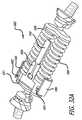
- FIG. 1Ais a perspective view, depicting an embodiment of an energy absorbing system mounted at a knee joint at full extension;
- FIG. 1Bis a perspective view, depicting the embodiment shown in FIG. 1A with the knee joint flexed to 90°;
- FIG. 2Ais a partial cross-sectional view, depicting one embodiment of an adjustment sub-structure
- FIG. 2Bis a partial cross-sectional view, depicting another embodiment of an adjustment sub-structure
- FIG. 2Cis an enlarged view, depicting an adjustment ring of FIG. 2B shown in a ratchet engaged state;
- FIG. 2Dis an enlarged view, depicting the adjustment ring of FIG. 2C in a ratchet release state
- FIGS. 3A and 3Bare partial views, depicting one embodiment of an energy absorbing device
- FIG. 4Ais a partial perspective view, depicting one embodiment of an energy absorbing device with a split collar
- FIG. 4Bis a cross-sectional view of the split collar shown in FIG. 4A in a locked configuration
- FIG. 4Cis a cross-sectional view of the split collar shown in FIG. 4A in an unlocked configuration
- FIG. 5Ais a partial perspective view, depicting one embodiment of an energy absorbing device with a split collar having compressible wings;
- FIG. 5Bis a cross-sectional view of the split collar shown in FIG. 5A in a locked configuration
- FIG. 5Cis a cross-sectional view of the split collar shown in FIG. 5A in an unlocked configuration
- FIG. 5Dis a perspective view, depicting one embodiment of an energy absorbing device with a split collar having one compressible wing;
- FIG. 6Ais a perspective view, depicting one embodiment of an energy absorbing device with a locking collar
- FIG. 6Bis a partial perspective view of the locking collar shown in FIG. 6A in a locked configuration
- FIG. 6Cis a cross-sectional view taken along line 6 C- 6 C of FIG. 6B of the locking collar;
- FIG. 7Ais a partial perspective view, depicting another embodiment of an energy absorbing device with a locking collar
- FIG. 7Bis a partial perspective view of the locking collar shown in FIG. 7A ;
- FIG. 7Cis a cross-sectional view taken along line 7 C- 7 C of FIG. 7B of the locking collar;
- FIG. 8Ais a planar view, depicting another embodiment of an energy absorbing device with a locking collar
- FIG. 8Bis a partial perspective view of the locking collar shown in FIG. 8A ;
- FIG. 8Cis a partial perspective view showing the ball bearings of the locking collar shown in FIG. 8A ;
- FIG. 8Dis a cross-sectional view of the locking collar shown in FIG. 8B ;
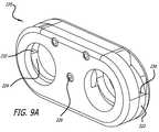
- FIGS. 9A through 9Ddepict various views of another embodiment of a locking collar
- FIG. 10Ais a perspective view, depicting another embodiment of an energy absorbing device with a locking collar in a locked configuration
- FIG. 10Bis a perspective view, depicting the energy absorbing device of FIG. 10A in an unlocked configuration
- FIG. 10Cis a partial perspective view showing the locking collar of FIG. 10A ;
- FIG. 10Dis a cross-sectional view of the locking collar shown in FIG. 10A ;
- FIGS. 11A through 11Cshow various views of another embodiment of a locking collar
- FIGS. 12A through 12Hshow one embodiment of an energy absorbing device and a method for adjusting the load of the device
- FIG. 13is a perspective view, depicting another embodiment of an energy absorbing device
- FIG. 14is a perspective view, depicting yet another embodiment of an energy absorbing device
- FIG. 15is a perspective view, depicting another embodiment of an energy absorbing device
- FIG. 16is a perspective view, depicting a sheath placed over an energy absorbing device
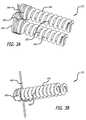
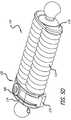
- FIG. 17Ais a perspective view, depicting an embodiment of a single spring energy absorbing device
- FIG. 17Bis a partial perspective view of the energy absorbing device shown in FIG. 17A ;
- FIG. 18Ais a perspective view, depicting another embodiment of a single spring energy absorbing device
- FIG. 18Bis a partial perspective view of the energy absorbing device shown in FIG. 18A ;
- FIG. 19Ais a perspective view, depicting an embodiment of a single spring energy absorbing device
- FIG. 19Bis a partial perspective view of the energy absorbing device shown in FIG. 19A ;
- FIGS. 20A and 20Bdepict partial perspective views showing another embodiment of a single spring energy absorbing device
- FIGS. 21A and 21Bdepict partial perspective views showing a non-circular single spring energy absorbing device with thickened walls
- FIG. 22Ais a perspective view, depicting an embodiment of a circular link element
- FIG. 22Bis a partial perspective view, depicting the circular link element of FIG. 22A ;
- FIG. 23Ais a perspective view, depicting another embodiment of a circular link element
- FIG. 23Bis a partial perspective view, depicting the circular link element of FIG. 23A ;
- FIG. 24Ais a perspective view, depicting an embodiment of a spring stop
- FIG. 24Bis a partial perspective view, depicting the spring stop of FIG. 24A disposed on a shaft;
- FIGS. 25A and 25Bdepict partial perspective views of another embodiment of a spring stop disposed on a shaft
- FIG. 26is a partial perspective view, depicting yet another embodiment of a spring stop disposed on a shaft
- FIG. 27is a partial perspective view, depicting another embodiment of a spring stop disposed on a shaft.
- FIG. 28is a perspective view, depicting an embodiment of a circular link with zero load on a spring showing flexible helical shims being disposed around a shaft to adjust the load of the circular link.
- FIG. 29Ais a perspective view, depicting a further embodiment of an energy absorbing device
- FIG. 29Bis a perspective view, depicting an opposite side of the device of FIG. 29A with compression springs removed;
- FIG. 29Cis a perspective view, depicting the adjustment core plates of FIGS. 29A and 29B ;
- FIG. 30Ais a perspective view, depicting yet a further embodiment of an energy absorbing device
- FIG. 30Bis a perspective view, depicting an opposite side of the device of FIG. 30A with compression springs removed;
- FIG. 30Cis a perspective view, depicting the adjustment core assembly of FIGS. 30A and 30B ;
- FIG. 31Ais a perspective view, depicting yet a further embodiment of an energy absorbing device
- FIG. 31Bis a partial perspective view, depicting an opposite side of the device of FIG. 31A with compression springs removed;
- FIG. 31Cis a perspective view, depicting the core adjustment subassembly of FIGS. 31A and 31B ;
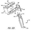
- FIG. 32Ais a perspective view, depicting an energy absorbing device including center and side squeeze mechanisms
- FIG. 32Bis a perspective view, depicting an opposite side of the device depicted in FIG. 32A ;
- FIG. 32Cis a perspective view, depicting the device of FIG. 32B with compression springs removed;
- FIG. 32Dis a perspective exploded view, depicting components of the adjustable subassembly of FIGS. 32A-C ;
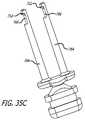
- FIG. 33Ais a perspective view, depicting an energy absorbing device including an adjustable spacer
- FIG. 33Bis a perspective view, depicting the device of FIG. 33A with the spacer removed;
- FIG. 33Cis a perspective view, depicting the device of FIGS. 33A and 33B with a nut of the adjustable spacer subassembly removed;
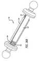
- FIG. 34Ais a perspective view, depicting an energy absorbing device including adjustable spacer structure
- FIG. 34Bis a perspective view, depicting the device of FIG. 34A with compression springs removed;
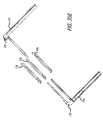
- FIG. 35Ais a perspective view, depicting an energy absorbing device including adjustable structure interacting with piston shafts;
- FIG. 35Bis a perspective view, depicting the device of FIG. 35A with compression springs removed;
- FIG. 35Cis a perspective view, depicting the device of FIG. 35B with adjustment core and block structure removed;
- FIG. 35Dis a perspective view, depicting an alternate approach to an adjustment assembly
- FIG. 35Eis an exploded view, depicting the components of FIG. 35D ;
- FIG. 36Ais a perspective view, depicting an interlocking link with threaded adjustment structure
- FIG. 36Bis a perspective view, depicting the device of FIG. 36A with a slider removed;
- FIG. 37is a perspective view, depicting an approach to a link which can be intra-operatively or post-operatively activated.
- the disclosed embodimentsare directed towards apparatus and methods for treating the knee joint. However, these embodiments may also be used in treating other body joints, and to alleviate pain associated with the function of diseased or misaligned members forming a body joint without limiting the range of motion of the joint.
- the embodiments described belowrelate to apparatuses and methods for adjusting the amount of load an energy absorbing device can manipulate. Some embodiments include an energy absorbing device including a dual spring member and other embodiments include the use of a single spring member.
- Certain of the embodimentsinclude energy absorbing devices designed to minimize and complement the dampening effect and energy absorption provided by the anatomy of the body, such as that found at a body joint. It has been postulated that to minimize pain, load manipulation or absorption of 1-40% of forces, in varying degrees, may be necessary. Variable load manipulation or energy absorption in the range of 5-20% can be a target for certain applications.
- the energy absorbing systemcan be initially configured to eliminate, variably reduce or manipulate loads to a desired degree, and to be later adjusted or altered as patient needs are better determined or change.
- the energy absorbing systemcan be designed to absorb medial compartment loads in a manner that completely preserves the articulating joint and capsular structures.
- One embodiment of the present inventionis load bypassing knee support system comprised of a kinematic load absorber, two contoured base components and a set of bone screws.
- the implanted systemis both extra articular and extra capsular and resides in the subcutaneous tissue on the medial (or lateral) aspect of the knee.
- the deviceis inserted through two small incisions above the medial femoral and tibial condyles.
- the base componentsare fixed to the medial cortices of the femur and tibia using bone screws.
- the energy absorberhaving a spring value of about twenty pounds can provide therapeutic benefit for patients of 275 pounds or less. Higher spring forces would provide greater reduction in joint load and may correlate to greater symptom (i.e., pain) relief.
- knee forceshave multiple components. There are a quadriceps force F Q and a ground reaction force F G directed generally longitudinally along a leg and there are lateral compartment forces F L and medial compartment forces F M . There is, however, no conventional clinical measure of F M or F L .
- the knee adduction moment(KAM) can be measured clinically. The measurements are useful as KAM can be considered to be a clinical surrogate measure for knee forces.
- knee adduction momentcorrelates with pain. That is, it would be expected that a group of people with diseased joints having lower KAM may not have pain whereas individuals with a relatively higher KAM would experience pain. Thus, an active reduction of knee adduction moment can reduce pain.
- the system of the present inventionreduces the KAM of the patient.
- a medial compartment of a knee of an average person with osteoarthritiscan benefit from an absorber set for compression between 1 mm and 10 mm, and preferably 3-6 mm with a spring or absorber element that accommodates a range from 20-60 pounds.
- the absorberis set for about 4 mm of such compression and a pre-determined load of about 40 pounds.
- each of the disclosed embodimentsvarious features can be incorporated from other of the disclosed embodiments.
- audible and textile feedback sub-systemscan be incorporated in the disclosed embodiments to both indicate translation of load adjustment structure as well as to exhibit locking and unlocking of subcomponents.
- each of the contemplated embodimentscan include springs machined to provide desirable energy absorbing which varies as the spring is compressed during various degrees of flexion and extension of joint markers to which the energy absorbing device is attached.
- the term “spring”is used throughout the description but it is contemplated to include other energy absorbing and compliant structures can be used to accomplish the functions of the invention as described in more detail below.
- any of the various disclosed approaches to achieving adjustment through a patient's skineither through direct engagement with the energy absorbing device with a tool or by applying forces to the device through the surface of the skin can be incorporated to fill a perceived need.
- each of the disclosed embodimentscan be so implanted and later activated and adjusted through a patient's skin.
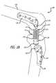
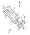
- FIGS. 1A-1Cone embodiment of an energy absorbing system 100 is shown with proximal 102 and distal 104 base components positioned upon first 106 and second 108 members, respectively of a typical body joint.
- the terminal end portions of the femur and tibiaare depicted without surrounding tissue.
- portions of the base componentsare contoured to match potential mounting surfaces of the femur and tibia.
- an energy absorbing device 110that is configured between and mounted to the base components.
- FIG. 1Ashows the knee joint at full extension with load being applied to springs 112 of the energy absorbing device, whereas FIG.
- FIG. 1Bshows the knee joint flexed to 90° with zero load being applied to the springs by virtue of the springs 112 being shorter than the length of the piston shafts 126 .
- the energy absorbing devicelengthens as the knee swings from full extension to flexion and subsequently shortens as the knee swings from flexion to full extension such that the springs begin to be compressed between the ends of the device to absorb the load that the knee articulating surfaces normally would experience.
- the energy absorbing device and base componentsare mounted across the joint such that once the springs have achieved a predetermined amount of compression, and therefore load, the articulating surfaces of the knee then begin to carry the load in combination with the energy absorbing device such that the energy absorbing device does not “bottom out”.
- the various energy absorbing devices in the present applicationare shown without a protective covering or sheath but it is contemplated that they can be within a protective covering or sheath to protect the moving elements from impingement by surrounding tissues and to prevent the devices from damaging surrounding tissue.
- an energy absorbing device 110includes a piston base 114 and an arbor base 116 .
- the piston baseis connected to a first or proximal mount 118 that is in connection with the proximal or first base component 102 .
- the arbor baseis connected to a second or distal mount 120 that is in connection with the distal or second base component 104 .
- holes 121are formed in the arbor base 116 to allow and/or contract fluid flow through the arbor during motion.
- a valvecan be added to convert the structure into a pneumatic absorber.
- a first or proximal end 122 of the springs 112is in connection with or in contact with the piston base, and a second or distal end of the springs are in contact with a spacer 124 when the knee joint is extended as shown in FIG. 1A .
- the size of the spacer 124can be adjusted to affect the amount of compression of the springs.
- the spacer 124can be formed of material providing compliance or spring behavior for added energy absorbing or as a built-in overload safety mechanism.
- piston shafts 126(not shown) of the piston base slide within arbor shafts (See FIG. 1B ) of the arbor base.
- two compression springsare shown in the energy absorbing device, one or more springs may be used.
- the configuration of the springsmay be varied to minimize device size while maximizing its energy absorbing capabilities.
- various types of springssuch as coaxial or leaf springs can be employed and the spring structure can be placed serially and adjusted one by one.
- the energy absorbing systemhas the capacity to absorb energy in addition to transfer energy from the joint.
- the energy absorption of the dual or single springcan be expressed as the product of force and displacement.
- elastomeric memberinclude thermoplastic polyurethanes such as Tecoflex, Tecothane, Tecoplast, Carbothene, Chronthane and ChronoFlex (grades AR, C, AL) which also could be employed as a dampener.
- materialssuch as Pebax, C-flex, Pellathane and silicone and silicone foam can also be employed.
- the energy absorbing devicemay include dampening devices such as dash pots.
- the spring elementis a storage or absorber device while the dashpot acts to dissipate the energy.
- Such embodiments or other structure defining a shock absorberwhich alter the velocity of displacement of the spring can be employed to thereby alter the energy absorption behavior.
- dampening devicesmay be used with the energy absorbing device, these elements could also be substituted with a material or other device with dampening characteristics (e.g., a small pore sponge).
- a pre-operative sessionis performed to assess the need at a joint and to map the articulation of the members 106 and 108 forming the joint. Attachment sites are also assessed pre-operatively.
- a first center of rotation locationis identified along the first member of a joint.
- accessis gained to an area proximate the first center of rotation location and the first base component 102 is fixed upon the first member in a manner maintaining use of the first center of rotation location.
- a second rotation locationis then identified along the second member of a joint and surgical access is obtained proximate the second rotation location.
- the second base component 104is fixed along the second member while maintaining use of the second rotation location.
- a subcutaneous channelis created between the first center of rotation and second rotation locations and the energy absorbing device 110 is inserted within the channel.
- the energy absorberis thereafter mounted to the bases.
- a tissue barriersuch as a sheath, may be placed about the energy absorber to protect joint anatomy or exclude the device from surrounding tissue.
- the connection of the absorber 110 to the bases 102 and 104 through attachable/detachable mounts 118 and 120provides a method for good attachment of the base to the bone and a more simple surgical technique for installing the absorber. It also allows a sheath and/or the wear components of the absorber/mount assembly to be removeable and/or replaceable without removing or replacing the base components. It further allows the wear components of the absorber/mount assembly and the base components to be different materials.
- the base componentscan be titanium or titanium alloy which promote osteo-integration and the wear components can be much harder materials such as cobalt chrome (e.g., Biodur CCM Plus), ceramic, or other durable materials that produce a minimal amount of particulate material or, if particulate material is generated, the smallest size of particulate material.
- cobalt chromee.g., Biodur CCM Plus
- the energy absorbing device 110can be initially configured to eliminate or reduce loads to a desired degree, and to be later adjusted or altered as patient needs are better determined or change. Accordingly, post-operative alterations are contemplated as are adjustments resulting from changing the diameter of a dampening component or a spring rate of a device. In this regard, it is also contemplated there be no initial or load manipulation until the interventional site heals and the device is firmly implanted or during an initial treatment episode to substantially reduce the effects and pain associated with a patient afflicted with osteoarthritis for a long time. The device can provide distraction forces and carry all of the load to an extent that the joint surfaces do not experience load when the joint is fully load bearing.
- This distractioncan continue for up to three months (or preferably two months) and then later the device can be adjusted to accomplish energy absorption without distraction.
- the methodcan involve removal or replacement of one or more components of the energy absorbing assembly.
- various degrees of non-invasive approachescan be employed as is practical for a given interventional procedure. Additional details and other embodiments of an energy absorbing system and method of implantation are shown and described in U.S. application Ser. No. 11/775,149, which has already been incorporated by reference.
- the deviceincludes an arbor shaft 130 including outwardly projecting and angled teeth.
- the shaftmay form part of the arbor base 116 .
- a spring-biased collar assembly 132is further provided and configured in a lockable arrangement with the shaft.
- the collar assembly 132is further provided with spring biased buttons 134 (here shown biased in a closed position by an elastomeric ring) having a distant terminal end. As the buttons are each depressed inwardly, this engagement with the teeth of the shaft disengages, thereby allowing the assembly 132 to move up or down.
- the spring-biased collar assembly 132is equipped with a two piece collar spring 136 which can assume both ratchet engaged ( FIG. 2C ) and ratchet released ( FIG. 2D ) configurations.
- the collardisengages from the shaft 130 and is permitted to be translated longitudinally.
- the angle and length of the teeth formed on the shaft and corresponding engaging structures of the collar assembliescan be configured to only allow translation if two points of the collar are sufficiently pressed.
- moving the spring biased collar assembly 132 proximally towards the first base component 102changes the stored potential energy in the spring 112 . If it is determined during or any time after surgery that the energy absorbing system should be adjusted, the collar/piston assembly is moved distally towards the first base component 102 to further compress the spring between the collar assembly and the piston base 114 .
- the deviceincludes two oppositely threaded spring stops 140 configured in a lockable arrangement with arbor shafts 142 of an arbor base 143 , the arbor shafts having threads or teeth.
- a rod 146 with teethcan be inserted in one of two directions between the two spring stops to create rotation of the spring stops. Rotation in one direction translates the spring stops proximally towards the arbor base, thereby decreasing the stored potential energy in the spring 142 . Rotation of the stops in the opposite direction compresses the spring between the stops and the piston base (not shown) when a load is applied to the spring.
- the rodcould be threaded and either permanently located in between the stops and rotated via a hex tool, or other tool, or inserted only during time of adjustment.
- FIGS. 4A through 4CAnother embodiment for adjusting the energy absorbing device 110 is shown in FIGS. 4A through 4C .
- This embodimentincludes a split collar 150 having a top portion 152 and a bottom portion 154 , with teeth 156 on the bottom portion (see FIG. 4C ).
- a pin 158is attached to the bottom portion of the collar and is biased upward with a spring 160 , which forces the top and bottom portions to be in a closed position as shown in FIG. 4B .
- the collarIn the closed or locked position, the collar is locked onto the shafts 162 of the arbor assembly 164 , which include indentations or teeth 166 to engage the teeth 156 of the bottom portion of the collar.
- a grommet 168is press fit into the pin, providing adjustment access via a tool, such as a 1 mm needle.
- a sheath 170may be disposed over the energy absorbing device, in which case the grommet is attached to the sheath so that the device can be adjusted without penetrating the sheath boundary.
- Other embodimentsdo not include a sheath.
- a userinserts a tool into the grommet 168 and presses downward overcoming the biasing force of the spring 160 and moving the bottom portion 154 away from the top portion 152 as shown in FIG. 4C .
- the springs 112may be adjusted by moving the split collar lock proximally or distally along the shafts of the arbor to increase or decrease the compression of the springs 112 . Once the desired compression of the spring is achieved when the joint is at full extension, the user can remove the tool from the grommet to allow the force of spring 160 to move the split collar into the closed or locked position.
- the bottom portion 154includes two wings 172 protruding from the sides of the split collar 150 .
- the embodiment shown in FIG. 5Dincludes one wing 172 protruding form only one side of the device.
- a usercan unlock the device with his fingers by pushing downward on the wings or wing to overcome the biasing force of the spring 160 and translate the collar from the closed or locked configuration, shown in FIG. 5B , into the open or unlocked configuration as shown in FIG. 5C . This allows for adjustments to be made from outside of the skin of the patient while the device is implanted.
- the grommet 168may or may not be included in these embodiments to allow access with a tool to unlock the split collar lock.
- the kneestarts out in an extended position.
- the kneeis then flexed to remove any load from the springs 112 .
- the adjustmentis made to the energy absorbing device as described above in relation to each different embodiment.
- the adjustmentcan be made over or through the skin of the patient.
- the teeth on the collar lockscan support up to about sixty-five pounds of pressure before yielding.
- FIGS. 6A through 6CAnother embodiment of a locking collar 180 is shown in FIGS. 6A through 6C .
- the locking collarincludes a center locking plate 182 with a top portion 184 and a bottom portion 186 connected together with an integrated spring 188 .
- the locking plateis nominally locked in grooves 190 around the shafts 192 of the arbor 194 .
- FIG. 6Cis a cross-sectional view taken along line 6 C- 6 C of FIG. 6B , and shows the device in the closed or locked configuration around the shafts.
- a button/spring mechanism 196that separates the portions of the plate is pressed by a user.
- Tapered surfaces 198 of the button/spring mechanismengage tapered surfaces 200 of the top and bottom portion of the center locking plate to push the top and bottom portions apart from one another and overcome the biasing force of the integrated spring. This configuration disengages the teeth of the locking plate from the grooves in the shafts.
- the collarcan be moved proximally or distally to adjust the positioning of the springs 112 .
- the adjustment of the devicecan be done by a user squeezing both sides of the button/spring mechanism at the same time through the skin of the patient, and then releasing the button/spring mechanism when the desired position of the spring is reached to lock the locking plate into the grooves of the shafts.
- FIGS. 7A through 7CAn embodiment similar to the embodiment shown in FIGS. 6A through 6C is shown in FIGS. 7A through 7C , and again, like reference numerals will be used to indicate like elements.
- the button/spring mechanism 196has been replaced with two separate buttons 202 held within the locking collar 180 by pins 204 .
- FIG. 7Cis a cross-section view taken along line 7 C- 7 C of FIG. 7B . Operation of the locking collar in this embodiment is similar to the above embodiment in FIGS. 6A through 6C .
- the two buttons 202 on each side of the deviceare pressed inward to separate the top and bottom portions 184 and 186 of the center locking plate 182 . Once the desired compression of the springs 112 is achieved, the buttons are released, thereby locking the center locking plate into the grooves 190 of the shafts 192 .
- FIGS. 8A through 8DAnother embodiment of a locking collar 210 is shown in FIGS. 8A through 8D .
- the locking collar of this embodimentis a “Grip Fast” collar, which includes a set of ball bearings 212 and a tapered locking plate 214 that locks the mechanism in place when the internal spring 216 is loaded.
- the locking collaris transitioned into the unlocked configuration when a user presses protruding wings 218 that remove pressure from the ball bearings, which in the locked configuration are pressed against the arbor shafts.
- FIG. 8Dis a cross-sectional view of the “Grip Fast” collar.
- FIGS. 9A through 9Dshow another embodiment of a locking collar 220 that includes a first locking arm 222 and a second locking arm 224 that engage with the teeth or grooves on the shafts of the arbor.
- the two locking armsare rotated on a pin 226 and two torsion springs 228 bias the arms in the locked position.
- a toolis used to push down on the tips 230 and 232 of the first and second locking arms, respectively, which disengages the locking arms from the grooves or teeth of the shafts and unlocks the collar. Once unlocked the collar can be moved to adjust the springs of the energy absorbing system.
- FIGS. 10A through 10DAnother embodiment of a locking collar 240 is shown in FIGS. 10A through 10D .
- the collarincludes a set of collets 242 with small teeth 243 which are locked into grooves 245 in shafts 244 when the spring stop 246 is forced against the set of collets.
- the collets and the spring stopare nominally biased against each other by two small inverted disc springs 248 in the locked configuration shown in FIG. 10A .
- a tool 249such as a 2 ⁇ 1 mm tool, is used to disengage the collar from the shafts by inserting the tool and rotating it, thereby separating the collets and spring stop.
- This unlocked configurationis shown in FIGS. 10B through 10D .
- the toolis rotated in an opposite direction and removed to re-engage the teeth 245 of the collets 244 with the grooves 245 of the shafts 244 .
- FIGS. 11A through 11CYet another embodiment of a stop collar 250 is shown in FIGS. 11A through 11C .
- the stop collarincludes a first spring stop slider 252 and a second spring stop slider 254 , each having two cutouts 256 that engage teeth or grooves 258 in shafts 260 .
- the cutouts 256 of the first and second spring stopsdisengage the grooves on the shafts when slid perpendicular to the shafts.
- the first and second slidersare separated by a single spring 262 and biased nominally in the locked position.
- the mechanismis disengaged once the first and second sliders are squeezed together to disengage the cutouts of the spring stop sliders from the shafts.
- FIG. 11Bshows the second spring stop slider in phantom so the cutouts of the first spring stop can be seen.
- FIG. 11Cshows the cross-section taken at line 11 C- 11 C of FIG. 11B , with the mechanism in the locked configuration and the first spring stop engaging the grooves of the shaft
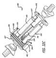
- FIGS. 12A through 12Hshow another embodiment of an energy absorbing device with a stop collar 270 , and a method of adjusting the device.
- FIG. 12Ashows the stop collar having an adjustment core 272 and an adjustment block 274 that are slidingly engaged together.
- the adjustment core and adjustment blockeach include a grip arm 276 that can be manipulated or squeezed by a user.
- Each grip arm 276includes a tooth 282 that comes in contact and rests within a slot 284 disposed on a wall 286 of the piston base 114 .
- the piston basealso includes pistons 288 that slide within shafts 290 of the arbor base 116 .
- the energy absorbing device 110will be in a similar configuration to that shown in FIG. 12A . In this position there is no load on the springs 112 and the stop collar 270 is locked into position on the teeth or grooves 292 of the shaft.
- the stop collar 270is forced into the unlocked configuration by squeezing the grip arms 276 of the adjustment core 272 and the adjustment block 274 towards one another. An audible sound will result when the spring finger 278 deflects off of the tooth 280 . The leg is then extended and the stop collar stops on the arbor base 116 at a zero load position as shown in FIG. 12C .
- FIG. 12Dshows the teeth 282 of the grip arms 276 hitting the piston walls 286 .
- the grip armsopen slightly for the teeth 282 to ride over the piston walls as shown in FIG. 12E .
- the teeth 282fall into slots 284 of the piston walls, linking the piston walls with the arms of the stop collar, as shown in FIG. 12F .
- the legWith the stop collar 270 still in the unlocked configuration, the leg is now flexed to a desired angle, and the shafts 290 extend away from the stop collar as shown in FIG. 12G .
- the arms 276 of the stop collarare released and the leg is extended to engage the stop collar and lock into the new position in the grooves 292 of the shafts 290 as shown in FIG. 12H .
- the stop collaris released, another audible sound will be created by the spring finger 278 .
- there is also another spring finger located on the adjustment corethat comes into contact with teeth on the arbor shaft to provide an audible sound when the stop collar is being translated over the arbor shaft. These audible sounds provide feedback to the user who may be adjusting the load of the device over the skin of the patient.
- FIG. 13An embodiment of the energy absorbing device 110 shown in FIG. 13 is similar to the device depicted in FIGS. 12A through 12H .
- this embodimentthere are no piston walls, but there is a post 294 on the piston base 116 , and the post includes a tapered end 296 and a notch 298 near the tapered end.
- the hook of the snap clipengages the notch of the piston post to connect the piston base with the stop collar.
- FIG. 14depicts another embodiment that is similar to last two embodiments, except in this embodiment, the piston base 114 includes a tapered post 310 that slides over a recess 312 in a spring tube 314 .
- the spring tubecovers the springs 112 of the energy absorbing device 110 and is in contact with the stop collar 270 .
- FIG. 15shows another similar embodiment, of the collar stop 270 .
- the long grip armshave been replaced with short arms 320 with recesses 322 configured for receiving the ends of pliers or another tool that can be used to grip and squeeze the short arms to unlock the stop collar 270 .
- this embodimentmay also include a sheath eyelet 323 for attachment to a sheath that covers the energy absorbing device.
- a sheath eyelet 332may be attached to the collar stop of the energy absorbing device 110 . There may also be a hole 334 to gain access to a grommet associated with the stop collar to lock or unlock the device in order to adjust the device.
- an energy absorbing device 350is shown to include a single spring 352 to absorb energy.
- the deviceincludes an arbor base 354 with an arbor casing 356 and a shaft 358 .
- a piston base 360with a piston casing 361 and a piston 362 that slides within the shaft of the arbor base.
- the piston casingis configured to slide under the arbor casing.
- a spring stop 364Surrounding the arbor shaft is a spring stop 364 with a proximal or first end 366 and a distal or second end 368 .
- a shim stop 374is positioned at the end of the post to keep the shims on the post and still allowing the shims to rotate about the post.
- a toolsuch as a needle or other instrument, is inserted into the most proximal top hole 376 to activate the most proximal shim 370 .
- An end of the instrument inserted through the top holeswill push against a first edge 380 of the shim and rotate the shim on the post 372 so that the shim slides inbetween the proximal end 366 of the spring stop 364 and the base of the arbor base 354 .
- FIG. 17Bshows two shims activated.
- any number of the shimscan be activated by inserting an instrument into consecutive top holes starting from the proximal end. To deactivate any number of the shims, the instrument is inserted into the bottom holes 378 disposed on the arbor casing. The end of the instrument inserted through the bottom holes will come into contact with a second edge 382 of the shim and rotate the shim in an opposite direction to remove the shim from between the spring stop and the arbor base. Any number of shims can be deactivated starting at the distal most activated shim. Activating and deactivating shims allow a user to adjust the compression of the position of the spring stop and the spring. Such adjustments can be made when the device 350 is unloaded such as during flexion.
- FIGS. 18A and 18BAnother embodiment of an energy absorbing device 350 a is shown in FIGS. 18A and 18B , and is similar to the embodiment of the device 350 shown in FIGS. 17A and 17B , and thus, like reference numerals will be used for like elements.
- the arbor casing 356includes a set of activation holes 384 on one side and a set of deactivation holes (not shown) on the opposite side of the arbor casing.
- This embodimentalso includes a spring stop 386 with a proximal end 388 and a distal end 390 and a recess 392 designed to allow a plurality of shims to be stored in a deactivated state as best shown in FIG. 18B .
- an instrumentis inserted into the most proximal activation hole where it engages a first edge 394 of the shim, and forces the shim to rotate about the post 372 and slide in between the proximal end of the spring stop and the arbor base 354 .
- Any number of the shimscan be activated by inserting the instrument into consecutive activation holes starting from the proximal most hole.
- the instrumentis inserted into the distal most deactivation holes where it engages a second edge 396 of the shim and rotates the shim back into the deactivated position.
- FIG. 18Bshows one shim activated.
- FIGS. 19A and 19BAnother embodiment of an energy absorbing device 350 b is shown in FIGS. 19A and 19B .
- this embodimentthere is a first set of shims 398 on a first post 400 connected to the arbor base 354 on one side of the spring stop 364 , and a second set of shims 402 on a second post (not shown) connected to the arbor base on the other side of the spring stop.
- the first and second sets of shimsare activated by pressing an instrument into the most proximal holes of the first and second sets of activation holes, which rotates the shims in between the proximal end 366 of the spring stop and the arbor base. This action compresses the spring 352 .
- an instrumentis inserted through the open top slot 406 of the arbor casing 356 and the piston casing 361 to rotate the shims back into the deactivated position near the wall of the spring stop. The user can deactivate any number of activated shims starting with the distal most activated shim.
- an energy absorbing device 410is shown with the spring and piston base removed for clarity.
- the device of this embodimentincludes a spring stop 412 with teeth 414 threaded onto a shaft 416 with threads 418 that is connected to the arbor base 420 .
- An arbor casing or wall 421includes a first opening 422 on one side and a second opening (not shown) on the opposite side of the casing. The first and second openings allows a tool 424 with teeth 426 , such as a needle or rod, to be inserted into the casing to mesh with the teeth of the spring stop and rotate the spring stop in one of two directions.
- Pushing the tool to rotate the spring stop in one directionrotates the spring stop in a distal direction down along the threads of the arbor shaft.
- Rotating the spring stop in the opposite direction with the tooltranslates the spring stop in a proximal direction up along the threads of the arbor shaft.
- Translating the spring stopdistally increases the compression on the spring and translating the spring stop proximally decreases the compression on the spring, thereby allowing the device to be adjusted to manipulate various loads.
- FIGS. 21A and 21BAnother embodiment of an energy absorbing device 430 is shown in FIGS. 21A and 21B .
- a non-circular link 432is shown with an arbor base 434 having an arbor wall or casing 436 , and a piston base 438 having piston wall or casing 440 .
- the non-circular cross-section of the linkallows the walls or casings of the bases to have added material making the walls thicker and therefore stronger. The added width of the walls will reduce rotation during load adjustments.
- the walls or casings of the energy absorbing devices 350 , 350 a , 350 b , and 410may be thin as previously shown or thicker as shown in FIGS. 21A and 21B .
- a circular link 450is shown with an arbor base 452 including an arbor shaft 454 with threads 456 , and a piston base 458 including a piston 460 that slides within the arbor shaft.
- an arbor base 452including an arbor shaft 454 with threads 456
- a piston base 458including a piston 460 that slides within the arbor shaft.
- a toolsuch as a 2 mm rod
- a toolis inserted into the top of the link to depress the finger lock, moving it away from a groove within the spring stop.
- the rodis positioned through a radial divot 468 of the spring stop. Adjustment occurs via multiple up and down actions or rocker of the rod.
- compression or decompression of the springcan range from between about 1 mm to about 3 mm.
- FIGS. 23A and 23Bshow another approach of a spring stop 470 that includes a first set of sloped notches 472 and a second set of sloped notches 474 that are sloped opposite to the first set.
- the spring stopis threaded onto threads 476 of arbor shaft 478 .
- a spring finger 482(see FIG. 23B ) is built into the spring stop and engages the recess of the shaft.
- the spring stopis translated in one direction using repeated rocking motions with a tool, such as a 2 mm rod, that engages the first set of sloped notches.
- the spring stopwill longitudinally translate until the spring finger snaps into the recess of the shaft making an audible click.
- This audible clicktells the user that the spring stop has been re-seated, which results in moving the spring stop about 1 mm, or more depending on the pitch of the threads on the shaft.
- the spring stopis translated in the opposite direction using the tool to engage the second set of sloped notches in a repeated motion.
- FIGS. 24A and 24BYet another approach of a link 490 is shown in FIGS. 24A and 24B .
- a spring stop 492is disposed on a shaft 494 of an arbor base 496 .
- the inner surface of the spring stopincludes raised bumps or teeth 498 that mesh with grooves 500 disposed on the arbor shaft.
- a toolsuch as a 1-2 mm rod, is inserted into the spring lock.
- the unlocked spring stopis then free to slide distally about 1 mm then rotate about 30° to lock in place. This helical movement can compress the spring (not shown) in order to adjust the device.
- the spring stopcan also be unlocked and moved proximally about 1 mm then rotated 30° in the reverse direction and locked in place to decrease the compression of the spring (not shown).
- the spring stopmay slide distally or proximally more or less than 1 mm depending on the design of the grooves on the shaft.
- FIGS. 25A and 25BAnother embodiment of a link 510 is shown in FIGS. 25A and 25B .
- the linkincludes a spring stop 512 having a tooth 514 on its inner surface to engage grooves 516 and a recess 517 on an arbor shaft 518 .
- the spring stopalso includes a spring finger 520 that prevents the spring stop from rotating or disengaging the grooves or recess of the shaft.
- the spring stopis rotated about 60° via a tool, such as a 2 mm rod, that is inserted into an opened or closed end hole 522 of the spring stop. The amount of rotation can be reduced by increasing the number of radial teeth sets on the shaft.
- the spring stopis slid along the shaft to a new location and then rotated back 60° to lock the spring stop in position.
- a link 530is shown having a split-ring spring stop 532 with a turnbuckle 534 . Inserting a tool, such as a hex tool 535 , into the turnbuckle separates the split-ring to allow translation of the split ring to the next set of teeth 536 on a shaft 538 , and creates the shift via teeth on the hex receiving part 540 .
- the split-ringcan be translated proximally or distally to adjust the load manipulating characteristics of the energy absorbing system.
- FIG. 27shows another embodiment of a link 550 having a spring stop 552 with teeth 554 that is threaded onto threads 556 of a shaft 558 .
- a tool 560 with a preformed internal member and a hook 562slides out of a sheath (not shown) and wraps around the teeth of the spring stop. Pulling the tool creates rotation of the spring to translate the spring stop along the threads of the shaft. This allows adjustment of the energy absorbing device by increasing or decreasing the compression of the spring (not shown).
- FIG. 28Another embodiment of a link 570 is shown in FIG. 28 .
- a spring stop 572is disposed over a shaft of an arbor base 574 .
- a spring 576is positioned over the shaft and is located between the spring stop and a piston base 578 .
- the piston baseincludes a piston or rod 580 that slides within the arbor shaft.
- flexible helical shims 582are inserted or removed from around the arbor shaft proximate to the spring stop.
- An accessible housing 584may be integrated with the spring stop or positioned proximate to the spring stop to capture the helical shims.
- a tool 586such as a cannula or needle with a rectangular cross-section, is used to insert shims into the accessible housing.
- a tip of the toolis inserted into the accessible housing and flexible helical shims are elastically deformed into a generally straight line to be transported through the tool and into the housing where the shims recoil or spring around the arbor shaft.
- the energy absorbing deviceis extended with zero load on the spring 576 .
- FIGS. 29A-CAn energy absorbing device 600 incorporating a push down mechanism for unlocking a load adjustment mechanism is depicted in FIGS. 29A-C .
- the deviceis provided with a piston base assembly 604 including a pivotable switch 606 including a bar extension 608 .
- the device 600further includes a series of adjustable core plates 610 , here shown including four such plates. Each plate includes a pair of spaced holes 612 sized to receive a single arbor shaft 614 as with previously described approaches.
- the arbor shaftsextend from an arbor base including relief holes 617 in communication with bores for receiving the piston shafts. Such relief holes 617 can be incorporated as described into each of the disclosed embodiments to aid in avoiding binding of the piston shafts.
- the relief holes 617can be valved so that body fluid is drawn in during flexion of anatomy and thus, the structure acts as a pneumatic absorber for extension of the anatomy.
- the arbor shafts 614include angled teeth 616 which engage corresponding structure forming a perimeter of the spaced holes. This corresponding structure can be in the form of ramps 618 which can be locked between the teeth 616 formed on the arbor shafts 614 .
- the interaction between the core plates 610 and the arbor shafts 614can provide the tactile or audible feedback necessary to indicate relative movement between the parts.
- Each of the plates 610also include a curved center slot 620 , adjacent plates 610 having oppositely curved center slots 620 .
- the slots 620are configured to receive the bar arm 608 of the pivotable switch 606 , which extends generally perpendicularly through the plates 606 .
- an audible or tactile feedbackcan indicate the unlocking of the plates 610 from their engagement with the arbor shafts 614 . That is, in a first position, the bar arm 608 of the switch 606 can lock the plates 610 within the teeth 616 of the arbor shafts 614 . Once the switch 60 is depressed and caused to pivot, the bar arm 608 moves within the center curved slots 620 of the plates 610 , thereby allowing relative lateral movement of the plates to occur. The lateral movement results in disengaging the plates from the arbor shafts 614 to an extent allowing the translation of the plates along the arbor shafts 614 .
- the operating length of the compression springs 622can be altered to thereby adjust the range of the load and energy absorbing capabilities of the energy absorbing device 600 . It is further contemplated that a tactile or audible click be induced as the plates 610 are moved along the arbor shafts 614 . The switch 606 can then be depressed again to once again lock the plates 610 relative to the arbor shafts 614 .
- an energy absorbing device 630includes a pivotable switch 632 which interacts with a bar arm 634 extending from one of two adjustment core plates.
- a first adjustment core plate 636includes the bar arm 634 which extends therefrom in a generally perpendicular manner.
- the second adjustment plate 638includes a channel 640 having an interior for receiving the bar arm 634 .
- the switch 632includes a terminal end portion 642 which engages the bar arm 634 such that in a first position, the terminal end portion 642 forces the bar arm 634 against an internal wall of the channel 640 to lock the plates 636 , 638 in a longitudinal position along arbor shafts 644 .
- the plates 636 , 638include spaced through holes 646 sized and shaped to both receive the arbor shaft as well as lockingly engage teeth 648 formed on the arbor shaft 644 . Moreover, such engagement is contemplated to provide auditory or tactile feedback necessary to indicate relative movement.
- the device 652includes a pivoting switch 654 operatively connected to a pin 656 .
- Operation of the switch 654results in longitudinal motion of the pin 656 through center holes 658 formed in adjustment plates 660 .
- Both the switch 654 and the pin 656ride within a center extension 662 which is configured between springs 664 configured about arbor shafts 666 .
- One end of the center extensionabuts a center most positioned adjustment plate 668 of a stack of adjustment plates 670 .
- the adjustment plates 668 , 670include holes 672 for locking engaging teeth 674 of the arbor shafts 666 in a manner to provide feedback upon relative movement.
- the center holes 658are again positioned and shaped to both cause the plates to lockingly engage the arbor shafts 666 as well as to move laterally with respect to one another upon activation of the switch 654 .
- the adjustment plates 668 , 670can be translated along the arbor shafts to adjust the springs 664 .
- an energy absorbing device 680include structure preventing accidental unlocking of adjustment structure.
- audible or tactile feedbackis incorporated into the device 680 to alert the patient or operator as to status concerning a locked or unlocked state as well as relative movement of parts during adjustment.
- Adjustment core plates 682 , 684each include curved wings 686 which extend longitudinally along the device 680 exterior of springs 688 configured about arbor shafts 690 .
- the plates 682 , 685each include spaced holes 692 with perimeter for lockingly engaging teeth 694 formed on the arbor shafts 690 and for providing necessary feedback concerning positioning or movement.
- the energy absorbing device 680also includes a piston base 696 including a center extension 697 configured between the springs 688 . At an opposite side of the device 680 and adjacent the arbor base 697 there is positioned a center extension 698 .
- the switch assemblyincludes a first extension 702 including a slot sized to receive a U-spring 703 and a second opposite end portion equipped with a tail 704 .
- the tail 704is sized and shaped to lockingly engage corresponding structure (not shown) formed in the piston base extension 697 .
- the U-spring 703includes ends 705 which extend through holes both round 706 and slotted 708 , formed in the plates 682 , 685 .
- the switch assembly 700operates to retain the U-spring 703 in an orthogonal position through its engagement with the adjustment plates 682 , 684 .
- the U-spring 703locks the adjustment plates 686 , 684 against the arbor shafts 690 and within its teeth 694 .
- the extension 702disengages from the U-spring 703 thereby permitting the U-spring to be bent and thus, unlocking the device.
- the curved wings 686 of the adjustment plates 682 , 684can be depressed to disengage the plates from the teeth 694 of the arbor shafts 690 so that translation of adjustment components is possible. As previously described, such translation results in altering when the compression springs will manipulate loads.
- the wings 686are then released to set the longitudinal position of the plates on the arbor shaft. After desired adjustment is accomplished, the switch can be re-seated to thereby again lock the plates 682 , 684 in position.
- FIGS. 33A-CAn approach to an energy absorbing device 710 including a spring loaded spacer assembly 712 is shown in FIGS. 33A-C .
- an adjustable spacer 718 of the spacer assembly 712can be translated and locked in place spaced from the arbor base 716 .
- This approachavoids the removal of material from arbor or link shafts, thus preserving the structural integrity of such members.
- the spacer 718 with pin 720 extending laterally therethroughis moved towards the piston base as best seen in FIG. 33B . So advancing the spacer 718 results in the pin engaging a slot formed in a spring biased nut 721 configured within the spacer 718 .
- the spring biased nut 721is placed in apposition with the compression springs 724 .
- the spacer 718benefits from the positional relationship between the nut 721 and the springs 724 such that a desired adjustment in energy absorbing capabilities of the spring is achieved.
- a compressible dome(not shown) can be configured over the pin to provide a desirable outer profile.
- the energy absorbing device 730can include a lever 732 which is accessible through a compressible dome 734 .
- the lever 732can be held in an inactive state by pins or suture (not shown) after implantation during a time when natural bone and tissue can grow over the energy absorbing device 730 to aid in its fixation at an interventional site.
- pins or suturescan subsequently be removed to activate the device so that desired energy absorbing is accomplished.
- Structure holding an energy absorbing device in an inactive statecan be incorporated into any one of the devices disclosed herein.
- the device 730when in an inactive state, the device 730 can be made to move through a normal range of motion with the only force being applied by the device 730 would be that generated by springs 735 of an adjustable spacer assembly 736 .
- the lever 732is permitted to operate without constraint (such as by removing the sutures or pins), an operator can cause the lever 732 to pivot by applying a force through the dome 734 .
- the lever 732which is pivotably supported by a spacer 738 , causes the nut 740 housed within the spacer 738 to translate longitudinally away from the arbor base 742 .
- the spacers 736translate longitudinally with the translation of the nut to thereby bring the compression springs 724 into the load manipulating capabilities of the device 730 .
- FIGS. 35A-Edepict an approach where adjustment structures can be additionally attached to cooperate with piston shafts of an energy absorbing device 750 .
- pins 752(See FIG. 35C ) attached to adjustment plates 754 , 756 including curved side wings 758 are translatable within slots 760 formed through arbor shafts 762 .
- the piston shafts 764additionally include cut-outs 766 along which the pins 752 are translatable. Accordingly, in addition to adjusting the position of the blocks 754 , 756 along the arbor shafts to adjust the absorber functioning of the compression springs 768 , through the engagement of the pins 752 with the piston shafts 764 , further adjustment can be achieved.
- adjustment assemblycan include all of the structures necessary to cooperate with the anchor shaft 762
- a contemplated alternative approachis to break the assembly into further sub-components.
- FIGS. 36D and Edepict five components defining an adjustment assembly which could replace a two-piece approach.
- a series of three additional plates 776can form the adjustment assembly. In this way, the detailed machining or forming which would be necessary to be configured into two pieces can be spread through further components thus streamlining manufacturing procedures.
- the link device 780includes a pair of longitudinally configured shafts 782 , 784 having threads 786 .
- the shaftseach include ball ends 788 for attaching to a mount of a complete energy absorbing system such as that depicted in FIG. 1A .
- Configured about the thread shafts 782 , 784are a pair of sliders 790 , each of the sliders defining curved arms extending longitudinally.
- the threaded shafts 782 , 784can be rotated to extend the overall length of the assembly.
- the energy absorbing assemblycan be configured with one or more tie-rods the ends of which can be accessed to adjust both length of the assembly and effective spring height.
- one end of a tie-rodcan be rotated to adjust length and another end or a second tie-rod can be rotated to alter an amount of pre-loading of a spring.
- a link assembly 790can incorporate structure permitting intra-operative or post-operative activation or adjustment (See FIG. 37 ). While shown for use in the particular link assembly 790 depicted, such or similar structure can be used in each of the approaches disclosed herein.
- a spring 792can be configured to effectively control positioning and loading of link ends 794 , 796 .
- a release wire 798can be placed into engagement with the spring 792 to retain it in a compressed configuration so as to cause it to be inactivated. Intra-operatively, the release wire 798 can be manipulated to permit the spring 792 to accomplish load manipulation. Alternatively, the release wire 798 can be manipulated by nicking the skin post-operatively to activate the spring 792 .
- an implantable sensor unitcan be configured at an interventional site to detect and keep track of indicators associated with changes in tissue density.
- the implantable sensor unitcan be configured for wireless communication with an external device and the external device can also be configured for wireless communication with the implantable sensor unit.
- the external deviceis adapted for retrieving, storing, and displaying, in human intelligible form, the tissue density data detected by the implantable sensor unit.
- the implantable sensorcan additionally be affixed to bone of the skeletal system such that it may monitor the bone, adjacent soft tissues, such as muscles, nerves and connective tissues.
- the sensormay be within or integral to an artificial implant attached to the skeletal system, attached to an artificial implant, adjacent to an artificial implant, or any combination of these locations.
- the implantable sensorcan include a sensor, a signal processor, a memory unit, a telemetry circuit, and a power source.
- the sensorcan be an acoustic transducer responsive to acoustic signals transmitted through human tissue. Further, it is fully contemplated that the sensor may include other electronics and components adapted for monitoring indicators of changes in tissue structure including deterioration and/or healing.
- the disclosed sensorhas applications throughout the skeletal system including the hip, knee, ankle, elbow and jaw joints and load bearing bones such as the skull and long bones. Such disclosed sensors are useful to evaluate tissue properties and detect changes to tissue in the skeletal system.
- the sensoralso has a particular application with respect to detecting changes in bone density as it relates to osteoporosis and the sensor can detect tissue density changes with respect to tissue around fixation implants, joint implants, or any other type of implant.
- an acoustic sensormay also be used to detect changes in viscosity.
- the sensormay be utilized to listen for changes in bodily systems and organs and alert healthcare professionals to any impending or potential problems.
- an energy absorbing devicecan manipulate to help reduce pain in a patient.
- These embodimentscan be used in any energy absorbing system for use throughout the body but have clear applications to articulating body structures such as joints.
- features and structures of certain of the disclosed embodimentscan be incorporated into other disclosed embodiments by replacing structure or complementing structure.
Landscapes
- Health & Medical Sciences (AREA)
- Orthopedic Medicine & Surgery (AREA)
- Life Sciences & Earth Sciences (AREA)
- Veterinary Medicine (AREA)
- Public Health (AREA)
- General Health & Medical Sciences (AREA)
- Animal Behavior & Ethology (AREA)
- Engineering & Computer Science (AREA)
- Biomedical Technology (AREA)
- Heart & Thoracic Surgery (AREA)
- Oral & Maxillofacial Surgery (AREA)
- Vascular Medicine (AREA)
- Transplantation (AREA)
- Cardiology (AREA)
- Rheumatology (AREA)
- Rehabilitation Therapy (AREA)
- Surgery (AREA)
- Neurology (AREA)
- Nuclear Medicine, Radiotherapy & Molecular Imaging (AREA)
- Medical Informatics (AREA)
- Molecular Biology (AREA)
- Prostheses (AREA)
Abstract
Description
Claims (17)
Priority Applications (13)
| Application Number | Priority Date | Filing Date | Title |
|---|---|---|---|
| US12/113,068US20080275557A1 (en) | 2007-05-01 | 2008-04-30 | Adjustable absorber designs for implantable device |
| US12/113,063US8088166B2 (en) | 2007-05-01 | 2008-04-30 | Adjustable absorber designs for implantable device |
| US12/113,044US8100967B2 (en) | 2007-05-01 | 2008-04-30 | Adjustable absorber designs for implantable device |
| US12/113,052US8409281B2 (en) | 2007-05-01 | 2008-04-30 | Adjustable absorber designs for implantable device |
| US12/113,072US8709090B2 (en) | 2007-05-01 | 2008-04-30 | Adjustable absorber designs for implantable device |
| US12/113,086US20080275552A1 (en) | 2007-05-01 | 2008-04-30 | Adjustable absorber designs for implantable device |
| PCT/US2009/002707WO2009134436A2 (en) | 2007-05-01 | 2009-04-30 | Adjustable absorber designs for implantable device |
| CA2725387ACA2725387A1 (en) | 2007-05-01 | 2009-04-30 | Adjustable absorber designs for implantable device |
| EP09739239AEP2273939A2 (en) | 2007-05-01 | 2009-04-30 | Adjustable absorber designs for implantable device |
| JP2011507467AJP5480885B2 (en) | 2007-05-01 | 2009-04-30 | Adjustable absorber design for implantable devices |
| AU2009241763AAU2009241763B2 (en) | 2007-05-01 | 2009-04-30 | Adjustable absorber designs for implantable device |
| US12/949,687US10327816B2 (en) | 2007-05-01 | 2010-11-18 | Adjustable absorber designs for implantable device |
| US13/354,498US20120116522A1 (en) | 2007-05-01 | 2012-01-20 | Adjustable absorber designs for implantable device |
Applications Claiming Priority (6)
| Application Number | Priority Date | Filing Date | Title |
|---|---|---|---|
| US11/743,097US20080275567A1 (en) | 2007-05-01 | 2007-05-01 | Extra-Articular Implantable Mechanical Energy Absorbing Systems |
| US11/743,605US10736746B2 (en) | 2007-05-01 | 2007-05-02 | Extra-articular implantable mechanical energy absorbing systems |
| US11/775,139US7611540B2 (en) | 2007-05-01 | 2007-07-09 | Extra-articular implantable mechanical energy absorbing systems and implantation method |
| US11/775,149US7655041B2 (en) | 2007-05-01 | 2007-07-09 | Extra-articular implantable mechanical energy absorbing systems and implantation method |
| US11/775,145US7678147B2 (en) | 2007-05-01 | 2007-07-09 | Extra-articular implantable mechanical energy absorbing systems and implantation method |
| US12/113,072US8709090B2 (en) | 2007-05-01 | 2008-04-30 | Adjustable absorber designs for implantable device |
Related Parent Applications (1)
| Application Number | Title | Priority Date | Filing Date |
|---|---|---|---|
| US11/743,097Continuation-In-PartUS20080275567A1 (en) | 2007-05-01 | 2007-05-01 | Extra-Articular Implantable Mechanical Energy Absorbing Systems |
Publications (2)
| Publication Number | Publication Date |
|---|---|
| US20080275563A1 US20080275563A1 (en) | 2008-11-06 |
| US8709090B2true US8709090B2 (en) | 2014-04-29 |
Family
ID=39940155
Family Applications (1)
| Application Number | Title | Priority Date | Filing Date |
|---|---|---|---|
| US12/113,072Expired - Fee RelatedUS8709090B2 (en) | 2007-05-01 | 2008-04-30 | Adjustable absorber designs for implantable device |
Country Status (1)
| Country | Link |
|---|---|
| US (1) | US8709090B2 (en) |
Cited By (40)
| Publication number | Priority date | Publication date | Assignee | Title |
|---|---|---|---|---|
| US20130282063A1 (en)* | 2007-08-17 | 2013-10-24 | Jmea Corporation | Dynamic Stabilization Systems And Devices For A Spine |
| US20150282848A1 (en)* | 2014-01-30 | 2015-10-08 | Rahul Vaidya | Knee brace fixation apparatus and method for application thereof |
| US9259322B2 (en)* | 2013-03-11 | 2016-02-16 | Embark Enterprises, Inc. | Canine internal stifle stabilization (CISS) system |
| US9282996B2 (en)* | 2013-03-13 | 2016-03-15 | Moximed, Inc. | Extra-articular implantable mechanical energy absorbing assemblies |
| US9289303B2 (en) | 2013-05-21 | 2016-03-22 | Linares Medical Devices, Llc | Dynamic interface support established between a ceramic hip joint ball and a supporting ball stem |
| US9532804B2 (en)* | 2013-03-15 | 2017-01-03 | Moximed, Inc. | Implantation approach and instrumentality for an energy absorbing system |
| US10349982B2 (en) | 2011-11-01 | 2019-07-16 | Nuvasive Specialized Orthopedics, Inc. | Adjustable magnetic devices and methods of using same |
| US10478232B2 (en) | 2009-04-29 | 2019-11-19 | Nuvasive Specialized Orthopedics, Inc. | Interspinous process device and method |
| US10617453B2 (en) | 2015-10-16 | 2020-04-14 | Nuvasive Specialized Orthopedics, Inc. | Adjustable devices for treating arthritis of the knee |
| US10646262B2 (en) | 2011-02-14 | 2020-05-12 | Nuvasive Specialized Orthopedics, Inc. | System and method for altering rotational alignment of bone sections |
| US10660675B2 (en) | 2010-06-30 | 2020-05-26 | Nuvasive Specialized Orthopedics, Inc. | External adjustment device for distraction device |
| US10729470B2 (en) | 2008-11-10 | 2020-08-04 | Nuvasive Specialized Orthopedics, Inc. | External adjustment device for distraction device |
| US10743794B2 (en) | 2011-10-04 | 2020-08-18 | Nuvasive Specialized Orthopedics, Inc. | Devices and methods for non-invasive implant length sensing |
| US10751094B2 (en) | 2013-10-10 | 2020-08-25 | Nuvasive Specialized Orthopedics, Inc. | Adjustable spinal implant |
| US10835290B2 (en) | 2015-12-10 | 2020-11-17 | Nuvasive Specialized Orthopedics, Inc. | External adjustment device for distraction device |
| US10918425B2 (en) | 2016-01-28 | 2021-02-16 | Nuvasive Specialized Orthopedics, Inc. | System and methods for bone transport |
| US11191579B2 (en) | 2012-10-29 | 2021-12-07 | Nuvasive Specialized Orthopedics, Inc. | Adjustable devices for treating arthritis of the knee |
| US11202707B2 (en) | 2008-03-25 | 2021-12-21 | Nuvasive Specialized Orthopedics, Inc. | Adjustable implant system |
| US11207110B2 (en) | 2009-09-04 | 2021-12-28 | Nuvasive Specialized Orthopedics, Inc. | Bone growth device and method |
| US11234849B2 (en) | 2006-10-20 | 2022-02-01 | Nuvasive Specialized Orthopedics, Inc. | Adjustable implant and method of use |
| US11246694B2 (en) | 2014-04-28 | 2022-02-15 | Nuvasive Specialized Orthopedics, Inc. | System for informational magnetic feedback in adjustable implants |
| US11304729B2 (en) | 2009-02-23 | 2022-04-19 | Nuvasive Specialized Orthhopedics, Inc. | Non-invasive adjustable distraction system |
| USRE49061E1 (en) | 2012-10-18 | 2022-05-10 | Nuvasive Specialized Orthopedics, Inc. | Intramedullary implants for replacing lost bone |
| US11357549B2 (en) | 2004-07-02 | 2022-06-14 | Nuvasive Specialized Orthopedics, Inc. | Expandable rod system to treat scoliosis and method of using the same |
| US11357547B2 (en) | 2014-10-23 | 2022-06-14 | Nuvasive Specialized Orthopedics Inc. | Remotely adjustable interactive bone reshaping implant |
| US11439449B2 (en) | 2014-12-26 | 2022-09-13 | Nuvasive Specialized Orthopedics, Inc. | Systems and methods for distraction |
| US11577097B2 (en) | 2019-02-07 | 2023-02-14 | Nuvasive Specialized Orthopedics, Inc. | Ultrasonic communication in medical devices |
| US11589901B2 (en) | 2019-02-08 | 2023-02-28 | Nuvasive Specialized Orthopedics, Inc. | External adjustment device |
| US11612416B2 (en) | 2015-02-19 | 2023-03-28 | Nuvasive Specialized Orthopedics, Inc. | Systems and methods for vertebral adjustment |
| US11696836B2 (en) | 2013-08-09 | 2023-07-11 | Nuvasive, Inc. | Lordotic expandable interbody implant |
| US11737787B1 (en) | 2021-05-27 | 2023-08-29 | Nuvasive, Inc. | Bone elongating devices and methods of use |
| US11766252B2 (en) | 2013-07-31 | 2023-09-26 | Nuvasive Specialized Orthopedics, Inc. | Noninvasively adjustable suture anchors |
| US11801187B2 (en) | 2016-02-10 | 2023-10-31 | Nuvasive Specialized Orthopedics, Inc. | Systems and methods for controlling multiple surgical variables |
| US11806054B2 (en) | 2021-02-23 | 2023-11-07 | Nuvasive Specialized Orthopedics, Inc. | Adjustable implant, system and methods |
| US11839410B2 (en) | 2012-06-15 | 2023-12-12 | Nuvasive Inc. | Magnetic implants with improved anatomical compatibility |
| US11857226B2 (en) | 2013-03-08 | 2024-01-02 | Nuvasive Specialized Orthopedics | Systems and methods for ultrasonic detection of device distraction |
| US11871974B2 (en) | 2007-10-30 | 2024-01-16 | Nuvasive Specialized Orthopedics, Inc. | Skeletal manipulation method |
| US11925389B2 (en) | 2008-10-13 | 2024-03-12 | Nuvasive Specialized Orthopedics, Inc. | Spinal distraction system |
| US12023073B2 (en) | 2021-08-03 | 2024-07-02 | Nuvasive Specialized Orthopedics, Inc. | Adjustable implant |
| US12213708B2 (en) | 2020-09-08 | 2025-02-04 | Nuvasive Specialized Orthopedics, Inc. | Remote control module for adjustable implants |
Families Citing this family (16)
| Publication number | Priority date | Publication date | Assignee | Title |
|---|---|---|---|---|
| WO2010106507A2 (en) | 2009-03-17 | 2010-09-23 | Mor Research Applications Ltd | Hallux abducto valgus assemblies |
| US9278004B2 (en) | 2009-08-27 | 2016-03-08 | Cotera, Inc. | Method and apparatus for altering biomechanics of the articular joints |
| CA2771332C (en) | 2009-08-27 | 2020-11-10 | Cotera, Inc. | Method and apparatus for force redistribution in articular joints |
| US10349980B2 (en) | 2009-08-27 | 2019-07-16 | The Foundry, Llc | Method and apparatus for altering biomechanics of the shoulder |
| US9861408B2 (en) | 2009-08-27 | 2018-01-09 | The Foundry, Llc | Method and apparatus for treating canine cruciate ligament disease |
| US9668868B2 (en) | 2009-08-27 | 2017-06-06 | Cotera, Inc. | Apparatus and methods for treatment of patellofemoral conditions |
| US8523948B2 (en)* | 2009-10-20 | 2013-09-03 | Moximed, Inc. | Extra-articular implantable mechanical energy absorbing assemblies having a tension member, and methods |
| JP5822933B2 (en) | 2010-08-29 | 2015-11-25 | ボンフィックス リミテッド | Orthopedic implants for treating bone deformities |
| US9468466B1 (en) | 2012-08-24 | 2016-10-18 | Cotera, Inc. | Method and apparatus for altering biomechanics of the spine |
| ITVR20130013A1 (en)* | 2013-01-21 | 2014-07-22 | Tecres Spa | EXTERNAL FIXING DEVICE FOR THE TREATMENT OF BONE FRACTURES |
| FR3004919B1 (en)* | 2013-04-30 | 2015-05-08 | Xavier Renard | IMPROVEMENT TO EXTERNAL FIXATORS |
| US9820786B2 (en)* | 2014-01-30 | 2017-11-21 | Rahul Vaidya | Knee hinge fixation apparatus and method for application thereof |
| WO2015157626A1 (en)* | 2014-04-11 | 2015-10-15 | Moximed, Inc. | Implantable assembly for a knee joint and method for mounting an implantable assembly for a knee joint |
| WO2017221243A1 (en)* | 2016-06-19 | 2017-12-28 | Orthospin Ltd. | User interface for strut device |
| WO2020095217A1 (en)* | 2018-11-06 | 2020-05-14 | Moradi Ali | External orthopedic fixation device |
| US11497527B1 (en)* | 2021-09-09 | 2022-11-15 | Texas Scottish Rite Hospital For Children | Orthopedic spring hinge systems and methods |
Citations (162)
| Publication number | Priority date | Publication date | Assignee | Title |
|---|---|---|---|---|
| US2632440A (en) | 1947-12-17 | 1953-03-24 | John M Hauser | Leg brace joint and lock |
| US2877033A (en) | 1956-03-16 | 1959-03-10 | Dreher Mfg Company | Artificial joint |
| US3242922A (en) | 1963-06-25 | 1966-03-29 | Charles B Thomas | Internal spinal fixation means |
| US3648294A (en) | 1969-02-08 | 1972-03-14 | Esfandiar Shahrestani | Endoprostheses, especially for hip joints |
| US3681786A (en) | 1970-07-13 | 1972-08-08 | Medical Eng Corp | Solid human prosthesis of varying consistency |
| US3779654A (en) | 1971-08-06 | 1973-12-18 | R Horne | Artificial joint |
| US3875594A (en) | 1973-08-27 | 1975-04-08 | Dow Corning | Surgically implantable prosthetic joint having load distributing flexible hinge |
| US3902482A (en) | 1974-05-21 | 1975-09-02 | George A Taylor | Mechanical joint for an orthopedic brace or prosthesis |
| US3988783A (en) | 1976-01-21 | 1976-11-02 | Richards Manufacturing Company, Inc. | Prosthetic collateral ligament |
| SU578063A1 (en) | 1971-05-20 | 1977-10-30 | Seppo Arnold | Orthopedic endoapparatus for restoring hip joint |
| SU578957A1 (en) | 1976-03-30 | 1977-11-05 | Pozdnikin Yurij | Method of reconstruction of cotyloid cavity at dysplasia of hip joint |
| GB1507953A (en) | 1976-01-29 | 1978-04-19 | Tallinsk Polt Inst | Orthopaedic apparatus |
| SU624613A1 (en) | 1977-05-10 | 1978-09-25 | Tikhonenkov Egor S | Method of treating congenital femur dislocation |
| SU640740A1 (en) | 1977-07-12 | 1979-01-05 | Предприятие П/Я В-2769 | Arrangement for developing mobility of the joint of lower extremities |
| SU704605A1 (en) | 1978-03-14 | 1979-12-25 | Е. С. Тихоненков и С. . И. Федоров | Method of fixing fragments of the femur after intertrochanteric and supratrochateric osteotomy |
| US4187841A (en) | 1978-07-07 | 1980-02-12 | Knutson Richard A | Bone compression or distraction device |
| SU719612A1 (en) | 1977-10-28 | 1980-03-05 | Tikhonenkov Egor S | Method of recessing cotyloid cavity |
| SU741872A1 (en) | 1978-05-04 | 1980-06-25 | за вители | Splint for treating femur congenital dislocation |
| US4246660A (en) | 1978-12-26 | 1981-01-27 | Queen's University At Kingston | Artificial ligament |
| US4308863A (en) | 1979-10-18 | 1982-01-05 | Ace Orthopedic Manufacturing, Inc. | External fixation device |
| US4353361A (en) | 1980-08-25 | 1982-10-12 | Foster Robert W | Orthotic/prosthetic joint |
| US4501266A (en) | 1983-03-04 | 1985-02-26 | Biomet, Inc. | Knee distraction device |
| SU1186204A1 (en) | 1984-05-28 | 1985-10-23 | Московский Ордена Ленина И Ордена Октябрьской Революции Авиационный Институт Им.Серго Орджоникидзе | Apparatus for surgical treatment of hip joint injures |
| US4570625A (en) | 1981-08-06 | 1986-02-18 | National Research Development Corporation | Apparatus for external fixation of bone fractures |
| US4576158A (en) | 1983-01-28 | 1986-03-18 | Region Wallone | Method for determining the stability of an orthopedic device composed of an external fixation bar during setting of bone fractures |
| CA1205602A (en) | 1982-09-10 | 1986-06-10 | William C. Bruchman | Prosthesis for tensile load-carrying tissue |
| SU1251889A1 (en) | 1984-01-27 | 1986-08-23 | Ленинградский Ордена Трудового Красного Знамени Научно-Исследовательский Детский Ортопедический Институт Им.Г.И.Турнера | Apparatus for dynamic unloading of hip joint |
| US4621627A (en) | 1984-12-18 | 1986-11-11 | Orthofix S.R.L. | External axial fixation device |
| US4637382A (en) | 1982-04-27 | 1987-01-20 | Brigham & Women's Hospital | Motion-guiding load-bearing external linkage for the knee |
| SU1316666A1 (en) | 1984-09-27 | 1987-06-15 | В. В. Василенкайтис | Arrangement for relieving the load of a joint |
| US4696293A (en) | 1982-09-30 | 1987-09-29 | Ciullo Jerome V | Hinged external fixator |
| US4759765A (en) | 1986-03-17 | 1988-07-26 | Minnesota Mining And Manufacturing Company | Tissue augmentation device |
| US4776851A (en) | 1986-07-23 | 1988-10-11 | Bruchman William C | Mechanical ligament |
| US4846842A (en) | 1987-06-25 | 1989-07-11 | Connolly & Mcmaster | Body joint rotation support device |
| US4863471A (en) | 1987-01-07 | 1989-09-05 | Sulzer Brothers Limited | Crucial ligament replacement for a knee joint |
| US4871367A (en) | 1987-09-03 | 1989-10-03 | Sutter Biomedical Corporation | Surgically implanted prosthesis |
| US4883486A (en) | 1988-05-31 | 1989-11-28 | Indu Kapadia | Prosthetic ligament |
| GB2223406A (en) | 1988-08-01 | 1990-04-11 | Univ Bristol | External fixator device |
| US4923471A (en) | 1989-10-17 | 1990-05-08 | Timesh, Inc. | Bone fracture reduction and fixation devices with identity tags |
| US4942875A (en) | 1986-03-03 | 1990-07-24 | American Cyanamid Company | Surgical repair device having absorbable and nonabsorbable components |
| EP0383419A1 (en) | 1989-02-15 | 1990-08-22 | Johnson & Johnson Professional Products GmbH | Orthopaedic fixator |
| SU1588404A1 (en) | 1988-06-12 | 1990-08-30 | Тартуский государственный университет | Device for functional unloading of coxofemoral joint in fractures of cotyloid cavity |
| US4959065A (en) | 1989-07-14 | 1990-09-25 | Techmedica, Inc. | Bone plate with positioning member |
| US4988349A (en) | 1987-01-21 | 1991-01-29 | Orthofix S.R.L. | Device for osteosynthesis |
| US5002574A (en) | 1989-08-18 | 1991-03-26 | Minnesota Mining And Manufacturing Co. | Tensioning means for prosthetic devices |
| US5011497A (en) | 1987-10-29 | 1991-04-30 | Atos Medical Ab | Joint prosthesis |
| US5019077A (en) | 1989-03-17 | 1991-05-28 | Orthofix S.R.L. | External splint |
| US5026372A (en) | 1987-11-05 | 1991-06-25 | Robert Sturtzkopf | Fixation device for the external adjusting of bone fragments |
| US5041112A (en) | 1989-11-30 | 1991-08-20 | Citieffe S.R.L. | External splint for the treatment of fractures of the long bones of limbs |
| SU1699441A1 (en) | 1981-07-08 | 1991-12-23 | Предприятие П/Я Г-4778 | Endoprosthesis for reconstructing hip joint |
| US5100403A (en) | 1990-06-08 | 1992-03-31 | Smith & Nephew Richards, Inc. | Dynamic elbow support |
| US5103811A (en) | 1990-07-09 | 1992-04-14 | Crupi Jr Theodore P | Body part or joint brace |
| US5121742A (en) | 1989-10-27 | 1992-06-16 | Baylor College Of Medicine | Lower extremity orthotic device |
| US5152280A (en) | 1989-01-04 | 1992-10-06 | Confida S.A.S | Bone support device |
| SU1769868A1 (en) | 1990-03-05 | 1992-10-23 | Le Ni Detskij Ortoped | Method for treatment consequences of shoulder plexus |
| GB2250919B (en) | 1989-11-14 | 1993-10-20 | Lazar Lvovich Rodnyansky | Endoappliance for hip joint restoration |
| US5318567A (en) | 1991-07-02 | 1994-06-07 | Olivier Vichard | Screw-on plate for treatment of fractures of the odontoid apophysis |
| US5352190A (en) | 1990-03-16 | 1994-10-04 | Q-Motus, Inc. | Knee brace |
| US5375823A (en) | 1992-06-25 | 1994-12-27 | Societe Psi | Application of an improved damper to an intervertebral stabilization device |
| US5405347A (en) | 1993-02-12 | 1995-04-11 | Zimmer, Inc. | Adjustable connector for external fixation rods |
| US5415661A (en) | 1993-03-24 | 1995-05-16 | University Of Miami | Implantable spinal assist device |
| US5456722A (en) | 1993-01-06 | 1995-10-10 | Smith & Nephew Richards Inc. | Load bearing polymeric cable |
| US5540688A (en) | 1991-05-30 | 1996-07-30 | Societe "Psi" | Intervertebral stabilization device incorporating dampers |
| US5575819A (en) | 1986-09-19 | 1996-11-19 | Imperial College Of Science And Technology | Artificial ligaments |
| US5578038A (en) | 1992-06-18 | 1996-11-26 | Slocum; D. Barclay | Jig for use in osteotomies |
| US5601553A (en) | 1994-10-03 | 1997-02-11 | Synthes (U.S.A.) | Locking plate and bone screw |
| JP2532346Y2 (en) | 1991-07-05 | 1997-04-16 | 本田技研工業株式会社 | Fuel vapor emission suppression device for internal combustion engine |
| US5624440A (en) | 1996-01-11 | 1997-04-29 | Huebner; Randall J. | Compact small bone fixator |
| RU2085148C1 (en) | 1994-12-02 | 1997-07-27 | Научно-производственное внедренческое малое предприятие "Медилар" | Endoapparatus for restoring coxofemoral joint |
| US5662650A (en) | 1995-05-12 | 1997-09-02 | Electro-Biology, Inc. | Method and apparatus for external fixation of large bones |
| US5662648A (en) | 1993-03-15 | 1997-09-02 | Orthofix S.R.L. | Method and apparatus for the external setting of fractures |
| US5681313A (en) | 1995-02-06 | 1997-10-28 | Karl Leibinger Medizintechnik Gmbh & Co. Kg | Device for the extension of bones |
| US5695496A (en) | 1995-01-17 | 1997-12-09 | Smith & Nephew Inc. | Method of measuring bone strain to detect fracture consolidation |
| US5716357A (en) | 1993-10-08 | 1998-02-10 | Rogozinski; Chaim | Spinal treatment and long bone fixation apparatus and method |
| US5803924A (en) | 1993-08-05 | 1998-09-08 | Hi-Shear Fastners Europe Limited | External fixator |
| US5873843A (en) | 1994-02-18 | 1999-02-23 | Btg International Limited | Assessing the state of union in a bone fracture |
| US5928234A (en) | 1997-10-10 | 1999-07-27 | Manspeizer; Sheldon | External fixture for tracking motion of a joint |
| US5976125A (en) | 1995-08-29 | 1999-11-02 | The Cleveland Clinic Foundation | External distractor/fixator for the management of fractures and dislocations of interphalangeal joints |
| US5976136A (en) | 1998-05-11 | 1999-11-02 | Electro Biology, Inc. | Method and apparatus for external bone fixator |
| US6036691A (en) | 1993-12-14 | 2000-03-14 | Richardson; James Bruce | External orthopedic fixator with patient-operated mechanism |
| JP2000503865A (en) | 1996-01-22 | 2000-04-04 | ハンデベロプ アクチボラゲット | Joint prosthetic device |
| US6113637A (en) | 1998-10-22 | 2000-09-05 | Sofamor Danek Holdings, Inc. | Artificial intervertebral joint permitting translational and rotational motion |
| US6139550A (en) | 1997-02-11 | 2000-10-31 | Michelson; Gary K. | Skeletal plating system |
| US6162223A (en) | 1999-04-09 | 2000-12-19 | Smith & Nephew, Inc. | Dynamic wrist fixation apparatus for early joint motion in distal radius fractures |
| US6176860B1 (en) | 1995-07-24 | 2001-01-23 | Hadasit Medical Research Services & Development Company, Ltd. | Orthopaedic fixator |
| US6193225B1 (en) | 1997-11-27 | 2001-02-27 | Tama Spring Co., Ltd. | Non-linear non-circular coiled spring |
| JP2001145647A (en) | 1999-11-19 | 2001-05-29 | Naohide Tomita | Knee joint load removing appliance |
| US6264696B1 (en) | 1999-01-04 | 2001-07-24 | Aesculap | Tibial knee prosthesis comprising a ball joint with double inserts |
| US6277124B1 (en) | 1999-10-27 | 2001-08-21 | Synthes (Usa) | Method and apparatus for ratcheting adjustment of bone segments |
| US20010020143A1 (en) | 1997-03-24 | 2001-09-06 | Stark John G. | Instrumented accelerometers for patient monitoring |
| US6315852B1 (en) | 1996-09-04 | 2001-11-13 | Anna Magrini | Production process of varying thickness osteosynthesis plates |
| US6355037B1 (en) | 2000-12-05 | 2002-03-12 | Smith & Nephew, Inc. | Apparatus and method of external skeletal support allowing for internal-external rotation |
| US6364881B1 (en) | 1997-07-30 | 2002-04-02 | Interpore Cross International | Longitudinally adjustable bone plates and method for use thereof |
| US6409729B1 (en) | 1998-05-19 | 2002-06-25 | Synthes (Usa) | Clamp assembly for an external fixation system |
| US20020095154A1 (en) | 2000-04-04 | 2002-07-18 | Atkinson Robert E. | Devices and methods for the treatment of spinal disorders |
| US20020151978A1 (en) | 1996-07-22 | 2002-10-17 | Fred Zacouto | Skeletal implant |
| US6482232B1 (en) | 1997-07-23 | 2002-11-19 | Biomet, Inc. | Apparatus and method for tibial fixation of soft tissue |
| US6494914B2 (en) | 2000-12-05 | 2002-12-17 | Biomet, Inc. | Unicondylar femoral prosthesis and instruments |
| US6527733B1 (en) | 2000-02-22 | 2003-03-04 | Dj Orthopedics, Llc | Hinge assembly for an orthopedic knee brace and knee brace incorporating the hinge assembly |
| US6540708B1 (en) | 2000-02-18 | 2003-04-01 | Sheldon Manspeizer | Polycentric joint for internal and external knee brace |
| JP2003102744A (en) | 2001-09-26 | 2003-04-08 | Newdeal Sa | Plate for fixing bone of joint, especially bone of metatarsophalangeal joint |
| US6572653B1 (en) | 2001-12-07 | 2003-06-03 | Rush E. Simonson | Vertebral implant adapted for posterior insertion |
| US20030216809A1 (en) | 2000-10-24 | 2003-11-20 | Ferguson Joe W. | Method for securing soft tissue to an artificial prosthesis |
| RU2217105C2 (en) | 2002-01-21 | 2003-11-27 | Федеральное государственное унитарное предприятие "Красноярский машиностроительный завод" | Endoapparatus for repairing hip joint |
| US6663631B2 (en) | 2000-12-01 | 2003-12-16 | Charles A. Kuntz | Method and device to correct instability of hinge joints |
| US6692497B1 (en) | 1998-03-06 | 2004-02-17 | Toermaelae Pertti | Bioabsorbable, deformable fixation plate |
| US6692498B1 (en) | 2000-11-27 | 2004-02-17 | Linvatec Corporation | Bioabsorbable, osteopromoting fixation plate |
| EP0953317B1 (en) | 1998-04-30 | 2004-04-07 | Fred Zacouto | Skeletal implant |
| US6752831B2 (en) | 2000-12-08 | 2004-06-22 | Osteotech, Inc. | Biocompatible osteogenic band for repair of spinal disorders |
| DE19855254B4 (en) | 1998-11-30 | 2004-08-05 | Richard, Hans-Albert, Prof. Dr. | Device for the retention and protection of damaged bones |
| US20040236329A1 (en)* | 2003-05-02 | 2004-11-25 | Panjabi Manohar M. | Dynamic spine stabilizer |
| RU2241400C2 (en) | 2002-09-23 | 2004-12-10 | Малахов Олег Алексеевич | Device for carrying hip joint decompression |
| US20040260302A1 (en) | 2003-06-19 | 2004-12-23 | Sheldon Manspeizer | Internal brace for distraction arthroplasty |
| US20040267179A1 (en) | 2003-06-30 | 2004-12-30 | Max Lerman | Knee unloading orthotic device and method |
| US20050085815A1 (en) | 2003-10-17 | 2005-04-21 | Biedermann Motech Gmbh | Rod-shaped implant element for application in spine surgery or trauma surgery, stabilization apparatus comprising said rod-shaped implant element, and production method for the rod-shaped implant element |
| US6884242B2 (en) | 2001-04-06 | 2005-04-26 | Society De Fabrication De Materiel Orthopedique, S.A. | Anterior plating system and method |
| US20050119744A1 (en) | 2000-01-11 | 2005-06-02 | Regeneration Technologies, Inc. | Soft and calcified tissue implants |
| US20050154390A1 (en) | 2003-11-07 | 2005-07-14 | Lutz Biedermann | Stabilization device for bones comprising a spring element and manufacturing method for said spring element |
| US20050192674A1 (en) | 1999-10-08 | 2005-09-01 | Ferree Bret A. | Prosthetic joints with contained compressible resilient members |
| US6966910B2 (en) | 2002-04-05 | 2005-11-22 | Stephen Ritland | Dynamic fixation device and method of use |
| US20050261680A1 (en) | 2001-03-28 | 2005-11-24 | Imperial College Innovations Ltd. | Bone fixated, articulated joint load control device |
| US6972020B1 (en) | 2001-06-01 | 2005-12-06 | New York University | Multi-directional internal distraction osteogenesis device |
| US6997940B2 (en) | 1998-02-06 | 2006-02-14 | Bonutti Ip, Llc | Bone suture assembly |
| US20060064169A1 (en) | 2002-09-10 | 2006-03-23 | Ferree Bret A | Shock-absorbing joint and spine replacements |
| US20060178744A1 (en) | 2005-02-04 | 2006-08-10 | Spinalmotion, Inc. | Intervertebral prosthetic disc with shock absorption |
| JP2006280951A (en) | 2005-03-31 | 2006-10-19 | Depuy Products Inc | Plate for uniting metatarsophalangeal joint |
| US7141073B2 (en) | 1993-11-01 | 2006-11-28 | Biomet, Inc. | Compliant fixation of external prosthesis |
| US20070043356A1 (en) | 2005-07-26 | 2007-02-22 | Timm Jens P | Dynamic spine stabilization device with travel-limiting functionality |
| US7188626B2 (en) | 1999-10-20 | 2007-03-13 | Warsaw Orthopedic, Inc. | Instruments and methods for stabilization of bony structures |
| EP1770302A1 (en) | 2005-09-30 | 2007-04-04 | Acandis GmbH & Co. KG | Damping method and device |
| US7201728B2 (en) | 2002-06-28 | 2007-04-10 | Shane Sterling | Anatomically designed orthopedic knee brace |
| US7235077B1 (en) | 2001-11-09 | 2007-06-26 | Board Of Regents Of The University And Community College System Of Nevada On Behalf Of The University Of Nevada, Reno | Bone fixation device and method |
| US7235102B2 (en) | 2002-05-10 | 2007-06-26 | Ferree Bret A | Prosthetic components with contained compressible resilient members |
| US7238203B2 (en) | 2001-12-12 | 2007-07-03 | Vita Special Purpose Corporation | Bioactive spinal implants and method of manufacture thereof |
| JP2007170969A (en) | 2005-12-21 | 2007-07-05 | Niigata Univ | Joint-free device inspection device |
| JP2007167318A (en) | 2005-12-21 | 2007-07-05 | Niigata Univ | Joint-free device inspection device |
| JP2007167319A (en) | 2005-12-21 | 2007-07-05 | Niigata Univ | Hip joint loader |
| US7241298B2 (en) | 2003-01-31 | 2007-07-10 | Howmedica Osteonics Corp. | Universal alignment guide |
| US20070161993A1 (en) | 2005-09-27 | 2007-07-12 | Lowery Gary L | Interspinous vertebral stabilization devices |
| US20070168033A1 (en) | 2003-08-01 | 2007-07-19 | Kim Daniel H | Prosthetic intervertebral discs having substantially rigid end plates and fibers between those end plates |
| US20070168036A1 (en) | 2003-10-23 | 2007-07-19 | Trans1 Inc. | Spinal motion preservation assemblies |
| US7252670B2 (en) | 1999-04-16 | 2007-08-07 | Sdgi Holdings, Inc. | Multi-axial bone anchor system |
| US20070198091A1 (en) | 2005-12-06 | 2007-08-23 | Boyer Michael L | Facet joint prosthesis |
| US20070198088A1 (en) | 2003-10-17 | 2007-08-23 | Lutz Biedermann | Flexible implant |
| US7261739B2 (en) | 2001-10-18 | 2007-08-28 | Spinecore, Inc. | Intervertebral spacer device having arch shaped spring element |
| US7282065B2 (en) | 2004-04-09 | 2007-10-16 | X-Spine Systems, Inc. | Disk augmentation system and method |
| US20070244488A1 (en) | 2006-03-03 | 2007-10-18 | Robert Metzger | Tensor for use in surgical navigation |
| US20070244483A9 (en) | 2005-05-10 | 2007-10-18 | Winslow Charles J | Inter-cervical facet implant with implantation tool |
| US7285134B2 (en) | 2003-10-22 | 2007-10-23 | Warsaw Orthopedic, Inc. | Vertebral body replacement implant |
| US7291150B2 (en) | 1999-12-01 | 2007-11-06 | Sdgi Holdings, Inc. | Intervertebral stabilising device |
| US7306605B2 (en) | 2003-10-02 | 2007-12-11 | Zimmer Spine, Inc. | Anterior cervical plate |
| US20070288014A1 (en) | 2006-06-06 | 2007-12-13 | Shadduck John H | Spine treatment devices and methods |
| US20080015593A1 (en) | 2005-03-24 | 2008-01-17 | Joachim Pfefferle | Bone plate |
| EP1005290B1 (en) | 1997-07-29 | 2008-02-13 | DePuy Spine, Inc. | Polyaxial locking plate |
| US20080071373A1 (en) | 2004-01-30 | 2008-03-20 | Molz Fred J | Orthopedic distraction implants and techniques |
| US20080071375A1 (en) | 2005-10-10 | 2008-03-20 | Carver Donna J | Artificial spinal disc replacement system and method |
| US7361196B2 (en) | 2005-02-22 | 2008-04-22 | Stryker Spine | Apparatus and method for dynamic vertebral stabilization |
| US20080097434A1 (en) | 2006-09-22 | 2008-04-24 | Missoum Moumene | Dynamic Stabilization System |
| US20080097441A1 (en) | 2004-10-20 | 2008-04-24 | Stanley Kyle Hayes | Systems and methods for posterior dynamic stabilization of the spine |
| EP1468655B1 (en) | 2003-03-26 | 2008-05-21 | Precimed S.A. | Locking bone plate |
| US20080132954A1 (en) | 2005-05-02 | 2008-06-05 | Kinetic Spine Technologies, Inc. | Spinal stabilisation implant |
| US20080275552A1 (en) | 2007-05-01 | 2008-11-06 | Exploramed Nc4, Inc. | Adjustable absorber designs for implantable device |
- 2008
- 2008-04-30USUS12/113,072patent/US8709090B2/ennot_activeExpired - Fee Related
Patent Citations (165)
| Publication number | Priority date | Publication date | Assignee | Title |
|---|---|---|---|---|
| US2632440A (en) | 1947-12-17 | 1953-03-24 | John M Hauser | Leg brace joint and lock |
| US2877033A (en) | 1956-03-16 | 1959-03-10 | Dreher Mfg Company | Artificial joint |
| US3242922A (en) | 1963-06-25 | 1966-03-29 | Charles B Thomas | Internal spinal fixation means |
| US3648294A (en) | 1969-02-08 | 1972-03-14 | Esfandiar Shahrestani | Endoprostheses, especially for hip joints |
| US3681786A (en) | 1970-07-13 | 1972-08-08 | Medical Eng Corp | Solid human prosthesis of varying consistency |
| SU578063A1 (en) | 1971-05-20 | 1977-10-30 | Seppo Arnold | Orthopedic endoapparatus for restoring hip joint |
| US3779654A (en) | 1971-08-06 | 1973-12-18 | R Horne | Artificial joint |
| US3875594A (en) | 1973-08-27 | 1975-04-08 | Dow Corning | Surgically implantable prosthetic joint having load distributing flexible hinge |
| US3902482A (en) | 1974-05-21 | 1975-09-02 | George A Taylor | Mechanical joint for an orthopedic brace or prosthesis |
| US3988783A (en) | 1976-01-21 | 1976-11-02 | Richards Manufacturing Company, Inc. | Prosthetic collateral ligament |
| GB1507953A (en) | 1976-01-29 | 1978-04-19 | Tallinsk Polt Inst | Orthopaedic apparatus |
| SU578957A1 (en) | 1976-03-30 | 1977-11-05 | Pozdnikin Yurij | Method of reconstruction of cotyloid cavity at dysplasia of hip joint |
| SU624613A1 (en) | 1977-05-10 | 1978-09-25 | Tikhonenkov Egor S | Method of treating congenital femur dislocation |
| SU640740A1 (en) | 1977-07-12 | 1979-01-05 | Предприятие П/Я В-2769 | Arrangement for developing mobility of the joint of lower extremities |
| SU719612A1 (en) | 1977-10-28 | 1980-03-05 | Tikhonenkov Egor S | Method of recessing cotyloid cavity |
| SU704605A1 (en) | 1978-03-14 | 1979-12-25 | Е. С. Тихоненков и С. . И. Федоров | Method of fixing fragments of the femur after intertrochanteric and supratrochateric osteotomy |
| SU741872A1 (en) | 1978-05-04 | 1980-06-25 | за вители | Splint for treating femur congenital dislocation |
| US4187841A (en) | 1978-07-07 | 1980-02-12 | Knutson Richard A | Bone compression or distraction device |
| US4246660A (en) | 1978-12-26 | 1981-01-27 | Queen's University At Kingston | Artificial ligament |
| US4308863A (en) | 1979-10-18 | 1982-01-05 | Ace Orthopedic Manufacturing, Inc. | External fixation device |
| US4353361A (en) | 1980-08-25 | 1982-10-12 | Foster Robert W | Orthotic/prosthetic joint |
| SU1699441A1 (en) | 1981-07-08 | 1991-12-23 | Предприятие П/Я Г-4778 | Endoprosthesis for reconstructing hip joint |
| US4570625A (en) | 1981-08-06 | 1986-02-18 | National Research Development Corporation | Apparatus for external fixation of bone fractures |
| US4637382A (en) | 1982-04-27 | 1987-01-20 | Brigham & Women's Hospital | Motion-guiding load-bearing external linkage for the knee |
| CA1205602A (en) | 1982-09-10 | 1986-06-10 | William C. Bruchman | Prosthesis for tensile load-carrying tissue |
| US4696293A (en) | 1982-09-30 | 1987-09-29 | Ciullo Jerome V | Hinged external fixator |
| US4576158A (en) | 1983-01-28 | 1986-03-18 | Region Wallone | Method for determining the stability of an orthopedic device composed of an external fixation bar during setting of bone fractures |
| US4501266A (en) | 1983-03-04 | 1985-02-26 | Biomet, Inc. | Knee distraction device |
| SU1251889A1 (en) | 1984-01-27 | 1986-08-23 | Ленинградский Ордена Трудового Красного Знамени Научно-Исследовательский Детский Ортопедический Институт Им.Г.И.Турнера | Apparatus for dynamic unloading of hip joint |
| SU1186204A1 (en) | 1984-05-28 | 1985-10-23 | Московский Ордена Ленина И Ордена Октябрьской Революции Авиационный Институт Им.Серго Орджоникидзе | Apparatus for surgical treatment of hip joint injures |
| SU1316666A1 (en) | 1984-09-27 | 1987-06-15 | В. В. Василенкайтис | Arrangement for relieving the load of a joint |
| US4621627A (en) | 1984-12-18 | 1986-11-11 | Orthofix S.R.L. | External axial fixation device |
| US4942875A (en) | 1986-03-03 | 1990-07-24 | American Cyanamid Company | Surgical repair device having absorbable and nonabsorbable components |
| US4759765A (en) | 1986-03-17 | 1988-07-26 | Minnesota Mining And Manufacturing Company | Tissue augmentation device |
| US4776851A (en) | 1986-07-23 | 1988-10-11 | Bruchman William C | Mechanical ligament |
| US5575819A (en) | 1986-09-19 | 1996-11-19 | Imperial College Of Science And Technology | Artificial ligaments |
| US4863471A (en) | 1987-01-07 | 1989-09-05 | Sulzer Brothers Limited | Crucial ligament replacement for a knee joint |
| US4988349A (en) | 1987-01-21 | 1991-01-29 | Orthofix S.R.L. | Device for osteosynthesis |
| US4846842A (en) | 1987-06-25 | 1989-07-11 | Connolly & Mcmaster | Body joint rotation support device |
| US4871367A (en) | 1987-09-03 | 1989-10-03 | Sutter Biomedical Corporation | Surgically implanted prosthesis |
| US5011497A (en) | 1987-10-29 | 1991-04-30 | Atos Medical Ab | Joint prosthesis |
| US5026372A (en) | 1987-11-05 | 1991-06-25 | Robert Sturtzkopf | Fixation device for the external adjusting of bone fragments |
| US4883486A (en) | 1988-05-31 | 1989-11-28 | Indu Kapadia | Prosthetic ligament |
| SU1588404A1 (en) | 1988-06-12 | 1990-08-30 | Тартуский государственный университет | Device for functional unloading of coxofemoral joint in fractures of cotyloid cavity |
| GB2223406A (en) | 1988-08-01 | 1990-04-11 | Univ Bristol | External fixator device |
| US5152280A (en) | 1989-01-04 | 1992-10-06 | Confida S.A.S | Bone support device |
| EP0383419A1 (en) | 1989-02-15 | 1990-08-22 | Johnson & Johnson Professional Products GmbH | Orthopaedic fixator |
| US5019077A (en) | 1989-03-17 | 1991-05-28 | Orthofix S.R.L. | External splint |
| US4959065A (en) | 1989-07-14 | 1990-09-25 | Techmedica, Inc. | Bone plate with positioning member |
| US5002574A (en) | 1989-08-18 | 1991-03-26 | Minnesota Mining And Manufacturing Co. | Tensioning means for prosthetic devices |
| US4923471A (en) | 1989-10-17 | 1990-05-08 | Timesh, Inc. | Bone fracture reduction and fixation devices with identity tags |
| US5121742A (en) | 1989-10-27 | 1992-06-16 | Baylor College Of Medicine | Lower extremity orthotic device |
| GB2250919B (en) | 1989-11-14 | 1993-10-20 | Lazar Lvovich Rodnyansky | Endoappliance for hip joint restoration |
| US5041112A (en) | 1989-11-30 | 1991-08-20 | Citieffe S.R.L. | External splint for the treatment of fractures of the long bones of limbs |
| SU1769868A1 (en) | 1990-03-05 | 1992-10-23 | Le Ni Detskij Ortoped | Method for treatment consequences of shoulder plexus |
| US5352190A (en) | 1990-03-16 | 1994-10-04 | Q-Motus, Inc. | Knee brace |
| US5100403A (en) | 1990-06-08 | 1992-03-31 | Smith & Nephew Richards, Inc. | Dynamic elbow support |
| US5103811A (en) | 1990-07-09 | 1992-04-14 | Crupi Jr Theodore P | Body part or joint brace |
| US5540688A (en) | 1991-05-30 | 1996-07-30 | Societe "Psi" | Intervertebral stabilization device incorporating dampers |
| US5318567A (en) | 1991-07-02 | 1994-06-07 | Olivier Vichard | Screw-on plate for treatment of fractures of the odontoid apophysis |
| JP2532346Y2 (en) | 1991-07-05 | 1997-04-16 | 本田技研工業株式会社 | Fuel vapor emission suppression device for internal combustion engine |
| US5578038A (en) | 1992-06-18 | 1996-11-26 | Slocum; D. Barclay | Jig for use in osteotomies |
| US5375823A (en) | 1992-06-25 | 1994-12-27 | Societe Psi | Application of an improved damper to an intervertebral stabilization device |
| US5456722A (en) | 1993-01-06 | 1995-10-10 | Smith & Nephew Richards Inc. | Load bearing polymeric cable |
| US5405347A (en) | 1993-02-12 | 1995-04-11 | Zimmer, Inc. | Adjustable connector for external fixation rods |
| US5662648A (en) | 1993-03-15 | 1997-09-02 | Orthofix S.R.L. | Method and apparatus for the external setting of fractures |
| US5415661A (en) | 1993-03-24 | 1995-05-16 | University Of Miami | Implantable spinal assist device |
| US5803924A (en) | 1993-08-05 | 1998-09-08 | Hi-Shear Fastners Europe Limited | External fixator |
| US5716357A (en) | 1993-10-08 | 1998-02-10 | Rogozinski; Chaim | Spinal treatment and long bone fixation apparatus and method |
| US7141073B2 (en) | 1993-11-01 | 2006-11-28 | Biomet, Inc. | Compliant fixation of external prosthesis |
| US6036691A (en) | 1993-12-14 | 2000-03-14 | Richardson; James Bruce | External orthopedic fixator with patient-operated mechanism |
| US5873843A (en) | 1994-02-18 | 1999-02-23 | Btg International Limited | Assessing the state of union in a bone fracture |
| US5601553A (en) | 1994-10-03 | 1997-02-11 | Synthes (U.S.A.) | Locking plate and bone screw |
| RU2085148C1 (en) | 1994-12-02 | 1997-07-27 | Научно-производственное внедренческое малое предприятие "Медилар" | Endoapparatus for restoring coxofemoral joint |
| US5695496A (en) | 1995-01-17 | 1997-12-09 | Smith & Nephew Inc. | Method of measuring bone strain to detect fracture consolidation |
| US5681313A (en) | 1995-02-06 | 1997-10-28 | Karl Leibinger Medizintechnik Gmbh & Co. Kg | Device for the extension of bones |
| US5662650A (en) | 1995-05-12 | 1997-09-02 | Electro-Biology, Inc. | Method and apparatus for external fixation of large bones |
| US6176860B1 (en) | 1995-07-24 | 2001-01-23 | Hadasit Medical Research Services & Development Company, Ltd. | Orthopaedic fixator |
| US5976125A (en) | 1995-08-29 | 1999-11-02 | The Cleveland Clinic Foundation | External distractor/fixator for the management of fractures and dislocations of interphalangeal joints |
| US5624440A (en) | 1996-01-11 | 1997-04-29 | Huebner; Randall J. | Compact small bone fixator |
| JP2000503865A (en) | 1996-01-22 | 2000-04-04 | ハンデベロプ アクチボラゲット | Joint prosthetic device |
| US20020151978A1 (en) | 1996-07-22 | 2002-10-17 | Fred Zacouto | Skeletal implant |
| US6315852B1 (en) | 1996-09-04 | 2001-11-13 | Anna Magrini | Production process of varying thickness osteosynthesis plates |
| US6139550A (en) | 1997-02-11 | 2000-10-31 | Michelson; Gary K. | Skeletal plating system |
| US20010020143A1 (en) | 1997-03-24 | 2001-09-06 | Stark John G. | Instrumented accelerometers for patient monitoring |
| US6482232B1 (en) | 1997-07-23 | 2002-11-19 | Biomet, Inc. | Apparatus and method for tibial fixation of soft tissue |
| EP1005290B1 (en) | 1997-07-29 | 2008-02-13 | DePuy Spine, Inc. | Polyaxial locking plate |
| US6364881B1 (en) | 1997-07-30 | 2002-04-02 | Interpore Cross International | Longitudinally adjustable bone plates and method for use thereof |
| US5928234A (en) | 1997-10-10 | 1999-07-27 | Manspeizer; Sheldon | External fixture for tracking motion of a joint |
| US6193225B1 (en) | 1997-11-27 | 2001-02-27 | Tama Spring Co., Ltd. | Non-linear non-circular coiled spring |
| US6997940B2 (en) | 1998-02-06 | 2006-02-14 | Bonutti Ip, Llc | Bone suture assembly |
| US6692497B1 (en) | 1998-03-06 | 2004-02-17 | Toermaelae Pertti | Bioabsorbable, deformable fixation plate |
| EP0953317B1 (en) | 1998-04-30 | 2004-04-07 | Fred Zacouto | Skeletal implant |
| US5976136A (en) | 1998-05-11 | 1999-11-02 | Electro Biology, Inc. | Method and apparatus for external bone fixator |
| US6409729B1 (en) | 1998-05-19 | 2002-06-25 | Synthes (Usa) | Clamp assembly for an external fixation system |
| US6113637A (en) | 1998-10-22 | 2000-09-05 | Sofamor Danek Holdings, Inc. | Artificial intervertebral joint permitting translational and rotational motion |
| DE19855254B4 (en) | 1998-11-30 | 2004-08-05 | Richard, Hans-Albert, Prof. Dr. | Device for the retention and protection of damaged bones |
| US6264696B1 (en) | 1999-01-04 | 2001-07-24 | Aesculap | Tibial knee prosthesis comprising a ball joint with double inserts |
| US6162223A (en) | 1999-04-09 | 2000-12-19 | Smith & Nephew, Inc. | Dynamic wrist fixation apparatus for early joint motion in distal radius fractures |
| US7252670B2 (en) | 1999-04-16 | 2007-08-07 | Sdgi Holdings, Inc. | Multi-axial bone anchor system |
| US20050192674A1 (en) | 1999-10-08 | 2005-09-01 | Ferree Bret A. | Prosthetic joints with contained compressible resilient members |
| US7188626B2 (en) | 1999-10-20 | 2007-03-13 | Warsaw Orthopedic, Inc. | Instruments and methods for stabilization of bony structures |
| US6277124B1 (en) | 1999-10-27 | 2001-08-21 | Synthes (Usa) | Method and apparatus for ratcheting adjustment of bone segments |
| JP2001145647A (en) | 1999-11-19 | 2001-05-29 | Naohide Tomita | Knee joint load removing appliance |
| US7291150B2 (en) | 1999-12-01 | 2007-11-06 | Sdgi Holdings, Inc. | Intervertebral stabilising device |
| US20050119744A1 (en) | 2000-01-11 | 2005-06-02 | Regeneration Technologies, Inc. | Soft and calcified tissue implants |
| US6540708B1 (en) | 2000-02-18 | 2003-04-01 | Sheldon Manspeizer | Polycentric joint for internal and external knee brace |
| US6527733B1 (en) | 2000-02-22 | 2003-03-04 | Dj Orthopedics, Llc | Hinge assembly for an orthopedic knee brace and knee brace incorporating the hinge assembly |
| US20020095154A1 (en) | 2000-04-04 | 2002-07-18 | Atkinson Robert E. | Devices and methods for the treatment of spinal disorders |
| US20050049708A1 (en) | 2000-04-04 | 2005-03-03 | Atkinson Robert E. | Devices and methods for the treatment of spinal disorders |
| US20030216809A1 (en) | 2000-10-24 | 2003-11-20 | Ferguson Joe W. | Method for securing soft tissue to an artificial prosthesis |
| US6692498B1 (en) | 2000-11-27 | 2004-02-17 | Linvatec Corporation | Bioabsorbable, osteopromoting fixation plate |
| US6663631B2 (en) | 2000-12-01 | 2003-12-16 | Charles A. Kuntz | Method and device to correct instability of hinge joints |
| US6355037B1 (en) | 2000-12-05 | 2002-03-12 | Smith & Nephew, Inc. | Apparatus and method of external skeletal support allowing for internal-external rotation |
| US6494914B2 (en) | 2000-12-05 | 2002-12-17 | Biomet, Inc. | Unicondylar femoral prosthesis and instruments |
| US6752831B2 (en) | 2000-12-08 | 2004-06-22 | Osteotech, Inc. | Biocompatible osteogenic band for repair of spinal disorders |
| US20050261680A1 (en) | 2001-03-28 | 2005-11-24 | Imperial College Innovations Ltd. | Bone fixated, articulated joint load control device |
| US6884242B2 (en) | 2001-04-06 | 2005-04-26 | Society De Fabrication De Materiel Orthopedique, S.A. | Anterior plating system and method |
| US6972020B1 (en) | 2001-06-01 | 2005-12-06 | New York University | Multi-directional internal distraction osteogenesis device |
| JP2003102744A (en) | 2001-09-26 | 2003-04-08 | Newdeal Sa | Plate for fixing bone of joint, especially bone of metatarsophalangeal joint |
| US7261739B2 (en) | 2001-10-18 | 2007-08-28 | Spinecore, Inc. | Intervertebral spacer device having arch shaped spring element |
| US7235077B1 (en) | 2001-11-09 | 2007-06-26 | Board Of Regents Of The University And Community College System Of Nevada On Behalf Of The University Of Nevada, Reno | Bone fixation device and method |
| US6572653B1 (en) | 2001-12-07 | 2003-06-03 | Rush E. Simonson | Vertebral implant adapted for posterior insertion |
| US7238203B2 (en) | 2001-12-12 | 2007-07-03 | Vita Special Purpose Corporation | Bioactive spinal implants and method of manufacture thereof |
| RU2217105C2 (en) | 2002-01-21 | 2003-11-27 | Федеральное государственное унитарное предприятие "Красноярский машиностроительный завод" | Endoapparatus for repairing hip joint |
| US6966910B2 (en) | 2002-04-05 | 2005-11-22 | Stephen Ritland | Dynamic fixation device and method of use |
| US7235102B2 (en) | 2002-05-10 | 2007-06-26 | Ferree Bret A | Prosthetic components with contained compressible resilient members |
| US7201728B2 (en) | 2002-06-28 | 2007-04-10 | Shane Sterling | Anatomically designed orthopedic knee brace |
| US20060064169A1 (en) | 2002-09-10 | 2006-03-23 | Ferree Bret A | Shock-absorbing joint and spine replacements |
| RU2241400C2 (en) | 2002-09-23 | 2004-12-10 | Малахов Олег Алексеевич | Device for carrying hip joint decompression |
| US7241298B2 (en) | 2003-01-31 | 2007-07-10 | Howmedica Osteonics Corp. | Universal alignment guide |
| EP1468655B1 (en) | 2003-03-26 | 2008-05-21 | Precimed S.A. | Locking bone plate |
| US7029475B2 (en) | 2003-05-02 | 2006-04-18 | Yale University | Spinal stabilization method |
| US20040236329A1 (en)* | 2003-05-02 | 2004-11-25 | Panjabi Manohar M. | Dynamic spine stabilizer |
| US20040260302A1 (en) | 2003-06-19 | 2004-12-23 | Sheldon Manspeizer | Internal brace for distraction arthroplasty |
| US20070106299A1 (en) | 2003-06-19 | 2007-05-10 | Sheldon Manspeizer | Internal brace for distraction arthroplasty |
| US20040267179A1 (en) | 2003-06-30 | 2004-12-30 | Max Lerman | Knee unloading orthotic device and method |
| US20070168033A1 (en) | 2003-08-01 | 2007-07-19 | Kim Daniel H | Prosthetic intervertebral discs having substantially rigid end plates and fibers between those end plates |
| US7306605B2 (en) | 2003-10-02 | 2007-12-11 | Zimmer Spine, Inc. | Anterior cervical plate |
| US20070198088A1 (en) | 2003-10-17 | 2007-08-23 | Lutz Biedermann | Flexible implant |
| US20050085815A1 (en) | 2003-10-17 | 2005-04-21 | Biedermann Motech Gmbh | Rod-shaped implant element for application in spine surgery or trauma surgery, stabilization apparatus comprising said rod-shaped implant element, and production method for the rod-shaped implant element |
| US7285134B2 (en) | 2003-10-22 | 2007-10-23 | Warsaw Orthopedic, Inc. | Vertebral body replacement implant |
| US20070168036A1 (en) | 2003-10-23 | 2007-07-19 | Trans1 Inc. | Spinal motion preservation assemblies |
| US20050154390A1 (en) | 2003-11-07 | 2005-07-14 | Lutz Biedermann | Stabilization device for bones comprising a spring element and manufacturing method for said spring element |
| US20080071373A1 (en) | 2004-01-30 | 2008-03-20 | Molz Fred J | Orthopedic distraction implants and techniques |
| US7282065B2 (en) | 2004-04-09 | 2007-10-16 | X-Spine Systems, Inc. | Disk augmentation system and method |
| US20080097441A1 (en) | 2004-10-20 | 2008-04-24 | Stanley Kyle Hayes | Systems and methods for posterior dynamic stabilization of the spine |
| US20060178744A1 (en) | 2005-02-04 | 2006-08-10 | Spinalmotion, Inc. | Intervertebral prosthetic disc with shock absorption |
| US7361196B2 (en) | 2005-02-22 | 2008-04-22 | Stryker Spine | Apparatus and method for dynamic vertebral stabilization |
| US20080015593A1 (en) | 2005-03-24 | 2008-01-17 | Joachim Pfefferle | Bone plate |
| JP2006280951A (en) | 2005-03-31 | 2006-10-19 | Depuy Products Inc | Plate for uniting metatarsophalangeal joint |
| US20080132954A1 (en) | 2005-05-02 | 2008-06-05 | Kinetic Spine Technologies, Inc. | Spinal stabilisation implant |
| US20070244483A9 (en) | 2005-05-10 | 2007-10-18 | Winslow Charles J | Inter-cervical facet implant with implantation tool |
| US20070043356A1 (en) | 2005-07-26 | 2007-02-22 | Timm Jens P | Dynamic spine stabilization device with travel-limiting functionality |
| US20070161993A1 (en) | 2005-09-27 | 2007-07-12 | Lowery Gary L | Interspinous vertebral stabilization devices |
| EP1770302A1 (en) | 2005-09-30 | 2007-04-04 | Acandis GmbH & Co. KG | Damping method and device |
| US20080071375A1 (en) | 2005-10-10 | 2008-03-20 | Carver Donna J | Artificial spinal disc replacement system and method |
| US20070198091A1 (en) | 2005-12-06 | 2007-08-23 | Boyer Michael L | Facet joint prosthesis |
| JP2007167319A (en) | 2005-12-21 | 2007-07-05 | Niigata Univ | Hip joint loader |
| JP2007170969A (en) | 2005-12-21 | 2007-07-05 | Niigata Univ | Joint-free device inspection device |
| JP2007167318A (en) | 2005-12-21 | 2007-07-05 | Niigata Univ | Joint-free device inspection device |
| US20070244488A1 (en) | 2006-03-03 | 2007-10-18 | Robert Metzger | Tensor for use in surgical navigation |
| US20070288014A1 (en) | 2006-06-06 | 2007-12-13 | Shadduck John H | Spine treatment devices and methods |
| US20080097434A1 (en) | 2006-09-22 | 2008-04-24 | Missoum Moumene | Dynamic Stabilization System |
| US20080275552A1 (en) | 2007-05-01 | 2008-11-06 | Exploramed Nc4, Inc. | Adjustable absorber designs for implantable device |
Non-Patent Citations (29)
| Title |
|---|
| Aldegheri, Roberto, M.D. et al.; "Articulated Distraction of the Hip-Conservative Surgery for Arthritis in Young Patients", Clinical Orthopaedics and Related Research, No. 301, pp. 94-101. |
| Benzel, Edward; "Qualitative Attributes of Spinal Implants"; in: Biomechanics of Spine Stabilization, 1995. |
| Buckwalter, Joseph A.; "Joint distraction for osteoarthritis"; The Lancet, Department of Orthopaedic Surgery, University of Iowa Hospitals and Clinics, vol. 347, Feb. 3, 1996, pp. 279-280. |
| Deie, Masataka, M.D. et al.; "A New Articulated Distraction Arthroplasty Device for Treatment of the Osteoarthritic Knee Joint: A Preliminary Report"; Arthroscopy: The Journal of Arthroscopic and Related Surgery; vol. 23, No. 8 (Aug. 2007): pp. 833-838. |
| Dienst, M. et al.; "Dynamic external fixation for distal radius fractures"; Clinical Orthopaedics and Related Research, 1997, vol. 338, pp. 160-171. |
| Hall, J. et al.; "Use of a hinged external fixator for elbow instability after severe distal humeral fracture"; Journal of Orthopaedic Trauma, 2000, vol. 14, No. 6, pp. 442-448. |
| Klein, D. et al.; "Percutaneous treatment of carpal, metacarpal, and phalangeal injuries"; Clinical Orthopaedics and Related Research, 200, vol. 375, pp. 116-125. |
| Krakauer, J. et al.; "Hinged device for fractures involving the proximal interphalangeal joint"; Clinical Orthopaedics and Related Research, 1996, vol. 327, pp. 29-37. |
| Lafeber et al., Unloading Joints to Treat Osteoarthritis, Including Joint Distraction, Current Opinion in Rheumatology 2006, 18;519-525. |
| Lapinskaya, V.S., et al., "An Endoapparatus for Restoration of the Hip Joint", Writers Collective, 2008, UDK 615.472.03:616.728.2-089.28. |
| Lapinskaya, Valentina Spiridonovna, "Treatment of Diseases and Injuries of Hip Joint Using a Method of Distraction", Kuibyshev Medical Institute, 1990. |
| Larionov d. Yu, et al., "Medical Devices", Scientific and Technical Bimonthly Journal, May-Jun. 2008. |
| Lentsner, A.A., et al., "Device for Functional Relief of Hip Joint in Cotyloid Cavity Fracture Cases", Ortop Travmatol Protez. Apr. 1990 (4) 44-6. |
| Madey, S. et al.; Hinged external fixation of the elbow: optimal axis alignment to minimize motion resistance; Journal of Orthopaedic Trauma, 2000, vol. 14, No. 1, pp. 41-47. |
| Nagai, et al., "B109 Mobility Evaluation of Hip-Joint Nonweight-Bearing Device", The Japan Society of Mechanical Engineers No. 02-26. |
| Neel, Michael D, M.D. et al.; "Early Multicenter Experience With a Noninvasive Expandable Prosthesis"; Clinical Orthopaedics and Related Research, 2003, No. 415, pp. 72-81. |
| Neel, Michael D., M.D.; "Repiphysis-Limb Salvage System for the Skeletally Immature"; Wright Medical Technology, Repiphysis Limb Salvage System, 2004, pp. 1-8. |
| Nockels, Russ P.; "Dynamic Stabilization in the Surgical Management of Painful Lumbar Spinal Disorders"; Spine, 2005, vol. 30, No. 16S, pp. S68-S72. |
| Orthofix; "Gentle Limb Deformity Correction"; website pages, http://www.eight-plate.com/, 2008. |
| Orthofix; "Xcaliber Articulated Ankle"; advertising brochure, May 2004. |
| Perry, Clayton R. et al.; "Patellar Fixation Protected with a Load-Sharing Cable: A Mechanical and Clinical Study"; Journal of Orthopaedic Trauma, 1988, vol. 2, No. 3, pp. 234-240. |
| Pollo, Fabian E. et al.; "Reduction of Medial Compartment Loads With Valgus Bracing of the Osteoarthritic Knee"; American Journal Sports Medicine, vol. 30, No. 3, 2002; pp. 414-421. |
| Sommerkamp, G. et al.; "Dynamic external fixation of unstable reactures of the distal part of the radius"; The Journal of Bone and Joint Surgery; 1994, vol. 76-A, No. 8, pp. 1149-1161. |
| Tomita, Naohide, "Development of Treatment Devices for Cartilage Regeneration", BME vol. 16, No. 2. |
| Uchikura, C. et al.; "Comparative study of nonbridging and bridging external fixators fro unstable distal raduis fractures"; Journal of Orthopaedic Science, 2004, vol. 9, pp. 560-565. |
| Weisstein. Jason S., M.D. et al.; "Oncologic Approaches to Pediatric Limb Preservation"; Journal of the American Academy of Orthopaedic Surgeons; vol. 13, No. 8, Dec. 2005. |
| Wilke, Hans-Joachim et al.; "Biomechanical Evaluation of a New Total Posterior-Element Replacement System"; Spine, 2006, vol. 31, No. 24, pp. 2790-2796. |
| Wilkins, Ross M., M.D. et al.; "The Phenix Expandable Prosthesis"; Clinical Orthopaedics and Related Research, No. 382, pp. 51-58. |
| Yamamoto, Ei et al.; "Effects of Stress Shielding on the Transverse Mechanical Properties of Rabbit Patellar Tendons"; Journal of Biomechanical Engineering, 2000, vol. 122, pp. 608-614. |
Cited By (74)
| Publication number | Priority date | Publication date | Assignee | Title |
|---|---|---|---|---|
| US11357549B2 (en) | 2004-07-02 | 2022-06-14 | Nuvasive Specialized Orthopedics, Inc. | Expandable rod system to treat scoliosis and method of using the same |
| US11712268B2 (en) | 2004-07-02 | 2023-08-01 | Nuvasive Specialized Orthopedics, Inc. | Expandable rod system to treat scoliosis and method of using the same |
| US11672684B2 (en) | 2006-10-20 | 2023-06-13 | Nuvasive Specialized Orthopedics, Inc. | Adjustable implant and method of use |
| US11234849B2 (en) | 2006-10-20 | 2022-02-01 | Nuvasive Specialized Orthopedics, Inc. | Adjustable implant and method of use |
| US20130282063A1 (en)* | 2007-08-17 | 2013-10-24 | Jmea Corporation | Dynamic Stabilization Systems And Devices For A Spine |
| US9445845B2 (en)* | 2007-08-17 | 2016-09-20 | Jmea Corporation | Dynamic stabilization systems and devices for a spine |
| US11871974B2 (en) | 2007-10-30 | 2024-01-16 | Nuvasive Specialized Orthopedics, Inc. | Skeletal manipulation method |
| US12076241B2 (en) | 2008-03-25 | 2024-09-03 | Nuvasive Specialized Orthopedics, Inc. | Adjustable implant system |
| US11202707B2 (en) | 2008-03-25 | 2021-12-21 | Nuvasive Specialized Orthopedics, Inc. | Adjustable implant system |
| US11925389B2 (en) | 2008-10-13 | 2024-03-12 | Nuvasive Specialized Orthopedics, Inc. | Spinal distraction system |
| US10729470B2 (en) | 2008-11-10 | 2020-08-04 | Nuvasive Specialized Orthopedics, Inc. | External adjustment device for distraction device |
| US11974782B2 (en) | 2008-11-10 | 2024-05-07 | Nuvasive Specialized Orthopedics, Inc. | External adjustment device for distraction device |
| US11304729B2 (en) | 2009-02-23 | 2022-04-19 | Nuvasive Specialized Orthhopedics, Inc. | Non-invasive adjustable distraction system |
| US11918254B2 (en) | 2009-02-23 | 2024-03-05 | Nuvasive Specialized Orthopedics Inc. | Adjustable implant system |
| US11602380B2 (en) | 2009-04-29 | 2023-03-14 | Nuvasive Specialized Orthopedics, Inc. | Interspinous process device and method |
| US10478232B2 (en) | 2009-04-29 | 2019-11-19 | Nuvasive Specialized Orthopedics, Inc. | Interspinous process device and method |
| US11207110B2 (en) | 2009-09-04 | 2021-12-28 | Nuvasive Specialized Orthopedics, Inc. | Bone growth device and method |
| US11944358B2 (en) | 2009-09-04 | 2024-04-02 | Nuvasive Specialized Orthopedics, Inc. | Bone growth device and method |
| US11497530B2 (en) | 2010-06-30 | 2022-11-15 | Nuvasive Specialized Orthopedics, Inc. | External adjustment device for distraction device |
| US12178477B2 (en) | 2010-06-30 | 2024-12-31 | Globus Medical Inc. | External adjustment device for distraction system |
| US10660675B2 (en) | 2010-06-30 | 2020-05-26 | Nuvasive Specialized Orthopedics, Inc. | External adjustment device for distraction device |
| US10646262B2 (en) | 2011-02-14 | 2020-05-12 | Nuvasive Specialized Orthopedics, Inc. | System and method for altering rotational alignment of bone sections |
| US11406432B2 (en) | 2011-02-14 | 2022-08-09 | Nuvasive Specialized Orthopedics, Inc. | System and method for altering rotational alignment of bone sections |
| US12290290B2 (en) | 2011-02-14 | 2025-05-06 | Nuvasive, Inc. | System and method for altering rotational alignment of bone sections |
| US11445939B2 (en) | 2011-10-04 | 2022-09-20 | Nuvasive Specialized Orthopedics, Inc. | Devices and methods for non-invasive implant length sensing |
| US10743794B2 (en) | 2011-10-04 | 2020-08-18 | Nuvasive Specialized Orthopedics, Inc. | Devices and methods for non-invasive implant length sensing |
| US10349982B2 (en) | 2011-11-01 | 2019-07-16 | Nuvasive Specialized Orthopedics, Inc. | Adjustable magnetic devices and methods of using same |
| US11918255B2 (en) | 2011-11-01 | 2024-03-05 | Nuvasive Specialized Orthopedics Inc. | Adjustable magnetic devices and methods of using same |
| US11123107B2 (en) | 2011-11-01 | 2021-09-21 | Nuvasive Specialized Orthopedics, Inc. | Adjustable magnetic devices and methods of using same |
| US11839410B2 (en) | 2012-06-15 | 2023-12-12 | Nuvasive Inc. | Magnetic implants with improved anatomical compatibility |
| USRE49061E1 (en) | 2012-10-18 | 2022-05-10 | Nuvasive Specialized Orthopedics, Inc. | Intramedullary implants for replacing lost bone |
| USRE49720E1 (en) | 2012-10-18 | 2023-11-07 | Nuvasive Specialized Orthopedics, Inc. | Intramedullary implants for replacing lost bone |
| US11191579B2 (en) | 2012-10-29 | 2021-12-07 | Nuvasive Specialized Orthopedics, Inc. | Adjustable devices for treating arthritis of the knee |
| US11871971B2 (en) | 2012-10-29 | 2024-01-16 | Nuvasive Specialized Orthopedics, Inc. | Adjustable devices for treating arthritis of the knee |
| US11213330B2 (en) | 2012-10-29 | 2022-01-04 | Nuvasive Specialized Orthopedics, Inc. | Adjustable devices for treating arthritis of the knee |
| US11857226B2 (en) | 2013-03-08 | 2024-01-02 | Nuvasive Specialized Orthopedics | Systems and methods for ultrasonic detection of device distraction |
| US9259322B2 (en)* | 2013-03-11 | 2016-02-16 | Embark Enterprises, Inc. | Canine internal stifle stabilization (CISS) system |
| US9622867B2 (en) | 2013-03-11 | 2017-04-18 | Embark Enterprises, Inc. | Quadruped stifle stabilization system |
| US9282996B2 (en)* | 2013-03-13 | 2016-03-15 | Moximed, Inc. | Extra-articular implantable mechanical energy absorbing assemblies |
| US9532804B2 (en)* | 2013-03-15 | 2017-01-03 | Moximed, Inc. | Implantation approach and instrumentality for an energy absorbing system |
| US9289303B2 (en) | 2013-05-21 | 2016-03-22 | Linares Medical Devices, Llc | Dynamic interface support established between a ceramic hip joint ball and a supporting ball stem |
| US12329374B2 (en) | 2013-07-31 | 2025-06-17 | Nuvasive Specialized Orthopedics Inc. | Noninvasively adjustable suture anchors |
| US11766252B2 (en) | 2013-07-31 | 2023-09-26 | Nuvasive Specialized Orthopedics, Inc. | Noninvasively adjustable suture anchors |
| US11696836B2 (en) | 2013-08-09 | 2023-07-11 | Nuvasive, Inc. | Lordotic expandable interbody implant |
| US12213893B2 (en) | 2013-08-09 | 2025-02-04 | Nuvasive, Inc. | Lordotic expandable interbody implant and method of using same |
| US10751094B2 (en) | 2013-10-10 | 2020-08-25 | Nuvasive Specialized Orthopedics, Inc. | Adjustable spinal implant |
| US11576702B2 (en) | 2013-10-10 | 2023-02-14 | Nuvasive Specialized Orthopedics, Inc. | Adjustable spinal implant |
| US20150282848A1 (en)* | 2014-01-30 | 2015-10-08 | Rahul Vaidya | Knee brace fixation apparatus and method for application thereof |
| US11246694B2 (en) | 2014-04-28 | 2022-02-15 | Nuvasive Specialized Orthopedics, Inc. | System for informational magnetic feedback in adjustable implants |
| US11357547B2 (en) | 2014-10-23 | 2022-06-14 | Nuvasive Specialized Orthopedics Inc. | Remotely adjustable interactive bone reshaping implant |
| US12226127B2 (en) | 2014-10-23 | 2025-02-18 | Nuvasive Specialized Orthopedics, Inc. | Remotely adjustable interactive implantable device |
| US11439449B2 (en) | 2014-12-26 | 2022-09-13 | Nuvasive Specialized Orthopedics, Inc. | Systems and methods for distraction |
| US11890043B2 (en) | 2014-12-26 | 2024-02-06 | Nuvasive Specialized Orthopedics, Inc. | Systems and methods for distraction |
| US11963705B2 (en) | 2014-12-26 | 2024-04-23 | Nuvasive Specialized Orthopedics, Inc. | Systems and methods for distraction |
| US12076051B2 (en) | 2015-02-19 | 2024-09-03 | Nuvasive Specialized Orthopedics, Inc. | Systems and methods for vertebral adjustment |
| US11612416B2 (en) | 2015-02-19 | 2023-03-28 | Nuvasive Specialized Orthopedics, Inc. | Systems and methods for vertebral adjustment |
| US10617453B2 (en) | 2015-10-16 | 2020-04-14 | Nuvasive Specialized Orthopedics, Inc. | Adjustable devices for treating arthritis of the knee |
| US11596456B2 (en) | 2015-10-16 | 2023-03-07 | Nuvasive Specialized Orthopedics, Inc. | Adjustable devices for treating arthritis of the knee |
| US10835290B2 (en) | 2015-12-10 | 2020-11-17 | Nuvasive Specialized Orthopedics, Inc. | External adjustment device for distraction device |
| US11504162B2 (en) | 2015-12-10 | 2022-11-22 | Nuvasive Specialized Orthopedics, Inc. | External adjustment device for distraction device |
| US12185982B2 (en) | 2015-12-10 | 2025-01-07 | Globus Medical Inc. | External adjustment device for distraction device |
| US10918425B2 (en) | 2016-01-28 | 2021-02-16 | Nuvasive Specialized Orthopedics, Inc. | System and methods for bone transport |
| US12263128B2 (en) | 2016-02-10 | 2025-04-01 | Nuvasive Specialized Orthopedics, Inc. | Systems and methods for controlling multiple surgical variables |
| US11801187B2 (en) | 2016-02-10 | 2023-10-31 | Nuvasive Specialized Orthopedics, Inc. | Systems and methods for controlling multiple surgical variables |
| US11577097B2 (en) | 2019-02-07 | 2023-02-14 | Nuvasive Specialized Orthopedics, Inc. | Ultrasonic communication in medical devices |
| US12274896B2 (en) | 2019-02-07 | 2025-04-15 | Nuvasive Specialized Orthopedics, Inc. | Ultrasonic communication in medical devices |
| US11589901B2 (en) | 2019-02-08 | 2023-02-28 | Nuvasive Specialized Orthopedics, Inc. | External adjustment device |
| US12213708B2 (en) | 2020-09-08 | 2025-02-04 | Nuvasive Specialized Orthopedics, Inc. | Remote control module for adjustable implants |
| US12004784B2 (en) | 2021-02-23 | 2024-06-11 | Nuvasive Specialized Orthopedics, Inc. | Adjustable implant, system and methods |
| US11806054B2 (en) | 2021-02-23 | 2023-11-07 | Nuvasive Specialized Orthopedics, Inc. | Adjustable implant, system and methods |
| US11944359B2 (en) | 2021-02-23 | 2024-04-02 | Nuvasive Specialized Orthopedics, Inc. | Adjustable implant, system and methods |
| US11737787B1 (en) | 2021-05-27 | 2023-08-29 | Nuvasive, Inc. | Bone elongating devices and methods of use |
| US12303169B1 (en) | 2021-05-27 | 2025-05-20 | Nuvasive, Inc. | Bone elongating devices and methods of use |
| US12023073B2 (en) | 2021-08-03 | 2024-07-02 | Nuvasive Specialized Orthopedics, Inc. | Adjustable implant |
Also Published As
| Publication number | Publication date |
|---|---|
| US20080275563A1 (en) | 2008-11-06 |
Similar Documents
| Publication | Publication Date | Title |
|---|---|---|
| US8709090B2 (en) | Adjustable absorber designs for implantable device | |
| US8088166B2 (en) | Adjustable absorber designs for implantable device | |
| US9907645B2 (en) | Adjustable absorber designs for implantable device | |
| US8123805B2 (en) | Adjustable absorber designs for implantable device | |
| US10596007B2 (en) | Extra-articular implantable mechanical energy absorbing systems and implantation method | |
| AU2014200703A1 (en) | Extra-articular implantable mechanical energy absorbing systems and implantation method |
Legal Events
| Date | Code | Title | Description |
|---|---|---|---|
| AS | Assignment | Owner name:EXPLORAMED NC4, INC., CALIFORNIA Free format text:ASSIGNMENT OF ASSIGNORS INTEREST;ASSIGNORS:MAKOWER, JOSHUA;SLONE, CLINTON N.;REGALA, ALAN C.;AND OTHERS;REEL/FRAME:021240/0745;SIGNING DATES FROM 20080708 TO 20080714 Owner name:EXPLORAMED NC4, INC., CALIFORNIA Free format text:ASSIGNMENT OF ASSIGNORS INTEREST;ASSIGNORS:MAKOWER, JOSHUA;SLONE, CLINTON N.;REGALA, ALAN C.;AND OTHERS;SIGNING DATES FROM 20080708 TO 20080714;REEL/FRAME:021240/0745 | |
| AS | Assignment | Owner name:MOXIMED, INC., CALIFORNIA Free format text:CHANGE OF NAME;ASSIGNOR:EXPLORAMED NC4, INC.;REEL/FRAME:021542/0760 Effective date:20080605 Owner name:MOXIMED, INC.,CALIFORNIA Free format text:CHANGE OF NAME;ASSIGNOR:EXPLORAMED NC4, INC.;REEL/FRAME:021542/0760 Effective date:20080605 | |
| AS | Assignment | Owner name:MOXIMED, INC., CALIFORNIA Free format text:ASSIGNMENT OF ASSIGNORS INTEREST;ASSIGNORS:MAKOWER, JOSHUA;SLONE, CLINTON N.;REGALA, ALAN C.;AND OTHERS;SIGNING DATES FROM 20110523 TO 20110524;REEL/FRAME:026333/0285 | |
| STCF | Information on status: patent grant | Free format text:PATENTED CASE | |
| MAFP | Maintenance fee payment | Free format text:PAYMENT OF MAINTENANCE FEE, 4TH YR, SMALL ENTITY (ORIGINAL EVENT CODE: M2551) Year of fee payment:4 | |
| FEPP | Fee payment procedure | Free format text:MAINTENANCE FEE REMINDER MAILED (ORIGINAL EVENT CODE: REM.); ENTITY STATUS OF PATENT OWNER: SMALL ENTITY | |
| LAPS | Lapse for failure to pay maintenance fees | Free format text:PATENT EXPIRED FOR FAILURE TO PAY MAINTENANCE FEES (ORIGINAL EVENT CODE: EXP.); ENTITY STATUS OF PATENT OWNER: SMALL ENTITY | |
| STCH | Information on status: patent discontinuation | Free format text:PATENT EXPIRED DUE TO NONPAYMENT OF MAINTENANCE FEES UNDER 37 CFR 1.362 | |
| FP | Lapsed due to failure to pay maintenance fee | Effective date:20220429 |