US8709078B1 - Ocular implant with substantially constant retinal spacing for transmission of nerve-stimulation light - Google Patents
Ocular implant with substantially constant retinal spacing for transmission of nerve-stimulation lightDownload PDFInfo
- Publication number
- US8709078B1 US8709078B1US13/204,610US201113204610AUS8709078B1US 8709078 B1US8709078 B1US 8709078B1US 201113204610 AUS201113204610 AUS 201113204610AUS 8709078 B1US8709078 B1US 8709078B1
- Authority
- US
- United States
- Prior art keywords
- eye
- ocular unit
- retina
- light
- posterior end
- Prior art date
- Legal status (The legal status is an assumption and is not a legal conclusion. Google has not performed a legal analysis and makes no representation as to the accuracy of the status listed.)
- Active, expires
Links
- 230000002207retinal effectEffects0.000titleabstractdescription22
- 239000007943implantSubstances0.000titledescription52
- 230000007383nerve stimulationEffects0.000titledescription25
- 230000005540biological transmissionEffects0.000titledescription2
- 210000001525retinaAnatomy0.000claimsabstractdescription123
- 210000005036nerveAnatomy0.000claimsabstractdescription53
- 230000004438eyesightEffects0.000claimsabstractdescription21
- 230000003287optical effectEffects0.000claimsdescription51
- 239000000463materialSubstances0.000claimsdescription39
- 210000004087corneaAnatomy0.000claimsdescription31
- 208000003098Ganglion CystsDiseases0.000claimsdescription26
- 208000005400Synovial CystDiseases0.000claimsdescription26
- 229920003229poly(methyl methacrylate)Polymers0.000claimsdescription25
- 239000004926polymethyl methacrylateSubstances0.000claimsdescription25
- 239000007789gasSubstances0.000claimsdescription12
- -1poly(methyl methacrylate)Polymers0.000claimsdescription12
- 230000008035nerve activityEffects0.000claimsdescription10
- 238000001514detection methodMethods0.000claimsdescription9
- 239000000560biocompatible materialSubstances0.000claimsdescription7
- 239000011261inert gasSubstances0.000claimsdescription7
- 230000004044responseEffects0.000claimsdescription6
- 210000003786scleraAnatomy0.000claimsdescription6
- 238000011282treatmentMethods0.000claimsdescription5
- 229920001169thermoplasticPolymers0.000claimsdescription2
- 239000004416thermosoftening plasticSubstances0.000claims1
- 230000000638stimulationEffects0.000abstractdescription72
- 238000000034methodMethods0.000abstractdescription30
- 230000004936stimulating effectEffects0.000abstractdescription15
- 230000037361pathwayEffects0.000abstractdescription10
- 208000007014Retinitis pigmentosaDiseases0.000abstractdescription8
- 230000036982action potentialEffects0.000abstractdescription8
- 208000002780macular degenerationDiseases0.000abstractdescription8
- 206010064930age-related macular degenerationDiseases0.000abstractdescription7
- 230000035807sensationEffects0.000abstractdescription6
- 201000010099diseaseDiseases0.000abstractdescription5
- 208000037265diseases, disorders, signs and symptomsDiseases0.000abstractdescription5
- 230000001976improved effectEffects0.000abstractdescription5
- 210000001508eyeAnatomy0.000description194
- 210000004027cellAnatomy0.000description42
- 210000004127vitreous bodyAnatomy0.000description27
- 210000001519tissueAnatomy0.000description23
- 210000002569neuronAnatomy0.000description19
- 239000013307optical fiberSubstances0.000description16
- 210000003128headAnatomy0.000description15
- 230000002093peripheral effectEffects0.000description11
- 239000011343solid materialSubstances0.000description11
- 239000012780transparent materialSubstances0.000description10
- 238000005516engineering processMethods0.000description9
- 210000000944nerve tissueAnatomy0.000description9
- 210000005252bulbus oculiAnatomy0.000description8
- 230000006870functionEffects0.000description8
- XLYOFNOQVPJJNP-UHFFFAOYSA-NwaterSubstancesOXLYOFNOQVPJJNP-UHFFFAOYSA-N0.000description8
- 206010025421MaculeDiseases0.000description7
- 238000010521absorption reactionMethods0.000description7
- 238000002513implantationMethods0.000description7
- 230000001537neural effectEffects0.000description7
- 210000000411amacrine cellAnatomy0.000description6
- 230000005484gravityEffects0.000description6
- 210000000578peripheral nerveAnatomy0.000description6
- 229920000642polymerPolymers0.000description6
- 210000004556brainAnatomy0.000description5
- 230000001886ciliary effectEffects0.000description5
- 238000003384imaging methodMethods0.000description5
- 230000002401inhibitory effectEffects0.000description5
- 210000003205muscleAnatomy0.000description5
- 230000000007visual effectEffects0.000description5
- 239000000017hydrogelSubstances0.000description4
- 230000031700light absorptionEffects0.000description4
- 239000002184metalSubstances0.000description4
- 239000000758substrateSubstances0.000description4
- 239000012815thermoplastic materialSubstances0.000description4
- 238000002834transmittanceMethods0.000description4
- 201000004569BlindnessDiseases0.000description3
- 241001465754MetazoaSpecies0.000description3
- 241000700605VirusesSpecies0.000description3
- 230000008901benefitEffects0.000description3
- 230000000903blocking effectEffects0.000description3
- 239000011248coating agentSubstances0.000description3
- 238000000576coating methodMethods0.000description3
- 210000003792cranial nerveAnatomy0.000description3
- 239000000835fiberSubstances0.000description3
- 239000012530fluidSubstances0.000description3
- 239000011521glassSubstances0.000description3
- 230000007774longtermEffects0.000description3
- 210000001328optic nerveAnatomy0.000description3
- 239000002861polymer materialSubstances0.000description3
- 238000012545processingMethods0.000description3
- 229920006352transparent thermoplasticPolymers0.000description3
- NIXOWILDQLNWCW-UHFFFAOYSA-Nacrylic acid groupChemical groupC(C=C)(=O)ONIXOWILDQLNWCW-UHFFFAOYSA-N0.000description2
- 238000004873anchoringMethods0.000description2
- 238000013459approachMethods0.000description2
- 210000003050axonAnatomy0.000description2
- 210000000133brain stemAnatomy0.000description2
- 230000004456color visionEffects0.000description2
- 230000006378damageEffects0.000description2
- 230000001066destructive effectEffects0.000description2
- 238000011161developmentMethods0.000description2
- 230000000694effectsEffects0.000description2
- 230000005611electricityEffects0.000description2
- 230000001939inductive effectEffects0.000description2
- 238000004519manufacturing processMethods0.000description2
- 229940127554medical productDrugs0.000description2
- 210000001259mesencephalonAnatomy0.000description2
- 208000015122neurodegenerative diseaseDiseases0.000description2
- 230000007935neutral effectEffects0.000description2
- 238000001020plasma etchingMethods0.000description2
- 238000007781pre-processingMethods0.000description2
- 230000008569processEffects0.000description2
- 238000004088simulationMethods0.000description2
- 210000000225synapseAnatomy0.000description2
- 238000012360testing methodMethods0.000description2
- 230000000451tissue damageEffects0.000description2
- 231100000827tissue damageToxicity0.000description2
- 230000001960triggered effectEffects0.000description2
- 230000001720vestibularEffects0.000description2
- 206010061818Disease progressionDiseases0.000description1
- 229920005479Lucite®Polymers0.000description1
- 229920005439Perspex®Polymers0.000description1
- 229920005372Plexiglas®Polymers0.000description1
- FAPWRFPIFSIZLT-UHFFFAOYSA-MSodium chlorideChemical compound[Na+].[Cl-]FAPWRFPIFSIZLT-UHFFFAOYSA-M0.000description1
- 230000004075alterationEffects0.000description1
- 210000001742aqueous humorAnatomy0.000description1
- 238000003491arrayMethods0.000description1
- 230000009286beneficial effectEffects0.000description1
- 210000005013brain tissueAnatomy0.000description1
- 210000003169central nervous systemAnatomy0.000description1
- 230000008859changeEffects0.000description1
- 230000001684chronic effectEffects0.000description1
- 210000000860cochlear nerveAnatomy0.000description1
- 150000001875compoundsChemical class0.000description1
- 230000008878couplingEffects0.000description1
- 238000010168coupling processMethods0.000description1
- 238000005859coupling reactionMethods0.000description1
- 230000003247decreasing effectEffects0.000description1
- 230000007547defectEffects0.000description1
- 230000007850degenerationEffects0.000description1
- 238000013461designMethods0.000description1
- 230000005750disease progressionEffects0.000description1
- 230000004424eye movementEffects0.000description1
- 210000002768hair cellAnatomy0.000description1
- 238000005286illuminationMethods0.000description1
- 238000002329infrared spectrumMethods0.000description1
- 230000008376long-term healthEffects0.000description1
- 208000018769loss of visionDiseases0.000description1
- 231100000864loss of visionToxicity0.000description1
- 238000005259measurementMethods0.000description1
- 230000007246mechanismEffects0.000description1
- 238000004476mid-IR spectroscopyMethods0.000description1
- 210000000653nervous systemAnatomy0.000description1
- 235000015097nutrientsNutrition0.000description1
- 210000000196olfactory nerveAnatomy0.000description1
- 230000035515penetrationEffects0.000description1
- 230000008447perceptionEffects0.000description1
- 229920002120photoresistant polymerPolymers0.000description1
- 102000004169proteins and genesHuman genes0.000description1
- 108090000623proteins and genesProteins0.000description1
- 238000011160researchMethods0.000description1
- 239000004065semiconductorSubstances0.000description1
- 230000008054signal transmissionEffects0.000description1
- 239000011780sodium chlorideSubstances0.000description1
- 125000006850spacer groupChemical group0.000description1
- 230000003595spectral effectEffects0.000description1
- 210000000278spinal cordAnatomy0.000description1
- 238000001356surgical procedureMethods0.000description1
- 239000013598vectorSubstances0.000description1
- 238000001429visible spectrumMethods0.000description1
- 210000000857visual cortexAnatomy0.000description1
- 230000004382visual functionEffects0.000description1
- 230000004393visual impairmentEffects0.000description1
Images


Classifications
- A—HUMAN NECESSITIES
- A61—MEDICAL OR VETERINARY SCIENCE; HYGIENE
- A61N—ELECTROTHERAPY; MAGNETOTHERAPY; RADIATION THERAPY; ULTRASOUND THERAPY
- A61N5/00—Radiation therapy
- A61N5/06—Radiation therapy using light
- A61N5/0601—Apparatus for use inside the body
- A—HUMAN NECESSITIES
- A61—MEDICAL OR VETERINARY SCIENCE; HYGIENE
- A61F—FILTERS IMPLANTABLE INTO BLOOD VESSELS; PROSTHESES; DEVICES PROVIDING PATENCY TO, OR PREVENTING COLLAPSING OF, TUBULAR STRUCTURES OF THE BODY, e.g. STENTS; ORTHOPAEDIC, NURSING OR CONTRACEPTIVE DEVICES; FOMENTATION; TREATMENT OR PROTECTION OF EYES OR EARS; BANDAGES, DRESSINGS OR ABSORBENT PADS; FIRST-AID KITS
- A61F2/00—Filters implantable into blood vessels; Prostheses, i.e. artificial substitutes or replacements for parts of the body; Appliances for connecting them with the body; Devices providing patency to, or preventing collapsing of, tubular structures of the body, e.g. stents
- A61F2/02—Prostheses implantable into the body
- A61F2/14—Eye parts, e.g. lenses or corneal implants; Artificial eyes
- A—HUMAN NECESSITIES
- A61—MEDICAL OR VETERINARY SCIENCE; HYGIENE
- A61N—ELECTROTHERAPY; MAGNETOTHERAPY; RADIATION THERAPY; ULTRASOUND THERAPY
- A61N5/00—Radiation therapy
- A61N5/06—Radiation therapy using light
- A61N5/0613—Apparatus adapted for a specific treatment
- A61N5/0622—Optical stimulation for exciting neural tissue
- A—HUMAN NECESSITIES
- A61—MEDICAL OR VETERINARY SCIENCE; HYGIENE
- A61N—ELECTROTHERAPY; MAGNETOTHERAPY; RADIATION THERAPY; ULTRASOUND THERAPY
- A61N5/00—Radiation therapy
- A61N5/06—Radiation therapy using light
- A61N2005/0635—Radiation therapy using light characterised by the body area to be irradiated
- A61N2005/0643—Applicators, probes irradiating specific body areas in close proximity
- A—HUMAN NECESSITIES
- A61—MEDICAL OR VETERINARY SCIENCE; HYGIENE
- A61N—ELECTROTHERAPY; MAGNETOTHERAPY; RADIATION THERAPY; ULTRASOUND THERAPY
- A61N5/00—Radiation therapy
- A61N5/06—Radiation therapy using light
- A61N2005/0658—Radiation therapy using light characterised by the wavelength of light used
- A61N2005/0659—Radiation therapy using light characterised by the wavelength of light used infrared
Definitions
- the inventionrelates generally to methods and apparatus for vision restoration and optical nerve stimulation, and more particularly to a method and apparatus for transmission of infrared optical stimulation to nerves (in contrast to the regular optical sensing rod and cone cells) in a human eye to obtain a sensation of vision.
- AMDadvanced or age-related macular degeneration
- RPretinitis pigmentosa
- Neuroprosthetic devicescircumvent non-functioning physiological structures (hair cells in the ear, rods and cones in the eye) which would normally transduce an external stimulus (sound, light) into an action potential.
- non-functioning physiological structureshair cells in the ear, rods and cones in the eye
- an external stimulussound, light
- neuroprosthesesto restore sight at various interventional anatomical locations: in the subretina, the epiretina, the optic nerve and in the visual cortex.
- These devicesapply an electric current pulse to stimulate the neurons of the visual system which is inherently hindered by a lack of spatial selectivity. Electrical current spread leads to imprecise nerve stimulation and limits the ability of the neuroprosthesis to restore function.
- ArgusTM II implantable deviceby Second Sight Medical Products, Inc., 12744 San Fernando Road—Building 3, Sylmar, Calif. 91342, USA, which is intended to treat profoundly blind people suffering from degenerative diseases such as RP.
- the Second Sight Medical Products, Inc. ArgusTM II systemworks by converting video images captured from a miniature camera, housed in the patient's glasses, into a series of small electrical pulses that are transmitted wirelessly to an epiretinal prosthesis array of electrodes implanted inside the eye on the retina. These pulses then stimulate the retina's remaining cells resulting in the corresponding perception of patterns of light in the brain. Patients supposedly learn to interpret these visual patterns thereby gaining some functional vision.
- the external parthas color imaging means (CCD or CMOS video camera), an eye-tracker, a head-motion tracker, a data processor, a patient's controller, a physician's local controller, a physician's remote controller, and a telemetry means.
- the color datais processed in the video data processing unit and encoded by time sequences of pulses separated by varying amounts of time, and also with the pulse duration being varied in time.
- the basis for the color encodingis the individual color code reference.
- Direct color stimulationis another operational basis for providing color perception.
- the electrodesstimulate the target cells so as to create a color image for the patient, corresponding to the original image as seen by the video camera.
- the physician's test unitcan be used to set up or evaluate and test the implant during or soon after implantation.
- These thin, strong, and flexible epiretinal devicesare constructed of or encapsulated in known biocompatible materials which will have a long working life in the eye's saline environment.
- the function of the implantsis to electrically stimulate the ganglion cell layer at the surface of the retina using controlled current sources. Due to the exceptionally low mass of the implant and its flexible, nearly planar form, patient discomfort and fluid drag caused by the implant minimized.
- These physical attributesalso substantially reduce the potential of harm to the most delicate structure of the eye, the retina, and therefore enhance the long term safety and biocompatibility of the device. Since no micro-cables are required to be attached to the device, and its overall form and edges are rounded, the device is not expected to stress the retina during chronic implantation. A provision is also made for nutrients to reach the retinal cells underneath the device to assure their long-term health.
- Electrical stimulationis limited since the spread of electricity does not allow separate or independent stimulation of individual retinal nerve cells or even small-enough groups of nerve cells for sharp or clear vision.
- This electrical-stimulation technologyis severely limited, as electricity spreads in human tissue and thus will severely limit the number of stimulation sites. Electrical stimulation thus greatly limits the number of sites that could be separately stimulated.
- the electrical-stimulation approachwill require implantation of a powered (e.g., an electrically powered) device, which has significant, difficult issues associated with obtaining power into the eye and using the power by devices in the eye.
- MEMSmicro-electro-mechanical-system
- U.S. Pat. No. 4,566,935issued to Hornbeck on Jan. 28, 1986, titled “Spatial Light Modulator and Method” and is incorporated herein by reference in its entirety.
- Hornbeckdescribed methods of fabrication of spatial light modulators with deflectable beams by plasma etching after dicing of a substrate into chips, each of the chips an SLM.
- Various architectures available with such plasma etching processwere disclosed and include metal cloverleafs for substrate addressing, metal flaps formed in a reflecting layer over a photoresist spacer layer, and torsion hinged flaps in a reflecting layer.
- Kintz et al.describe a virtual image display system is provided which is made thinner through the use of an immersed beam splitter, and in one embodiment, total internal reflection.
- the display systemincludes an imaging surface on which a source object is formed, a first optical element having a reflective function and a magnification function, a second optical element having a magnification function and an immersed beam splitting element positioned between the first and second optical elements, the immersed beam splitting element including a beam splitter surrounded by an optically transparent material having a refractive index greater than air.
- An illumination sourceprojects the source object formed at the imaging surface through the optically transparent material to the beam splitter.
- the beam splitterreflects the projected source object to the first optical element.
- the first optical elementmagnifies the projected source object and reflects a magnified virtual image of the projected source object to the beam splitter.
- the magnified virtual imagetraverses the beam splitter to the second optical element which magnifies the magnified virtual image to produce a compound magnified virtual image of the source object.
- the present inventionuses infrared nerve stimulation (INS) technology that uses infrared light to cause action potentials in nerve cells in the eye.
- INSinfrared nerve stimulation
- optical-stimulation technologyhas been developed to stimulate nerves.
- This INS technologycan achieve much higher precision and selectivity of stimulation than using electrical current to trigger nerve action potentials.
- the present technologyuses pulsed, infrared lasers to excite the neural tissue next to the retina directly and without tissue damage. The advent of this technology represents a paradigm shift in artificial nerve stimulation because it allows a high degree of spatial selectivity of neural stimulation without the need for tissue contact.
- the present inventionprovides an improved prosthesis and method for stimulating vision nerves to obtain a vision sensation that is useful for the patient that has lost vision due to AMD, RP, and other diseases.
- the inventionutilizes infrared light to cause action potentials in the retinal nerves similar to those action potentials that result from rods and cones stimulated by visible light in healthy retinas.
- an eyeglass-mounted systemis described that collects visual information and converts it into a stimulation pattern which is projected into the eye at an infrared wavelength with the purpose of causing an action potential in the retinal nerves with the purpose of recreating sight.
- the inventionprovides a pathway or “image pipe” for transmitting a stimulation pattern of infrared nerve-stimulation light, from an external infrared-light-emitting stimulator array, through the eye and focusing the stimulation pattern of infrared light on the nerves of the retina, especially the macula and fovea.
- the inventionprovides improved resolution down to a group of nerves, or even the individual nerve level, with sufficient energy density so as to cause desired action potentials in the targeted nerves.
- a laser diode emitting light with a 1.87-micron wavelengthstimulates nerves. This wavelength is important because devices capable of generating this wavelength are more available than longer mid-IR wavelengths.
- laser-diode light of a 2.1-micron wavelengthis used for nerve stimulation. Laser diodes that emit 2.1-micron-wavelength light are currently in research and would most likely work as well as other wavelengths, since this wavelength, when generated by a lamp-pumped solid-state laser, has been shown to be effective in stimulating nerves.
- a laser-diode device(having one or more emitters) outputs light that is used for nerve stimulation, wherein the light has a wavelength of between about 1.5 microns and about 6 microns; in various embodiments, for example, the wavelength is in the far infrared at about 1.5 microns, or about 1.51 microns, about 1.52 microns, about 1.53 microns, about 1.54 microns, about 1.55 microns, about 1.56 microns, about 1.57 microns, about 1.58 microns, about 1.59 microns, about 1.6 microns, about 1.61 microns, about 1.62 microns, about 1.63 microns, about 1.64 microns, about 1.65 microns, about 1.66 microns, about 1.67 microns, about 1.68 microns, about 1.69 microns, about 1.7 microns, about 1.71 microns, about 1.72 microns, about 1.73 microns, about 1.74 microns, about 1.75 microns
- the implantincludes a material which is both biocompatible in the eye and highly transmissive at the infrared stimulation wavelengths.
- the implantincludes optics that focus, collimate, and/or guide the stimulation light.
- the implantis sewn, stapled, or otherwise secured at the sclera and/or sewn, stapled, or otherwise secured to those locations where the eye's natural lens is normally attached.
- the implantis totally encapsulated within the eye, while in some other embodiments, the implant extends through the cornea and/or sclera.
- the ocular implantuses materials and design features already used in artificial corneas and intraocular lenses, for example, such as described in U.S. Pat.
- the ocular implantonce surgically implanted in the eye, the ocular implant has no internal moving parts relative to the eyeball and no internal electrical parts. Thus, such an ocular implant requires no internal or external electrical-power source. Additionally, the ocular implant does not impede movement of the eyeball after surgical implantation. In some embodiments, the freedom of eye movement relative to the external stimulator light can help provide enhanced patient comfort and enhanced perceived image resolution.
- the present inventionprovides a VCSEL array configured to output light pulses capable of optically stimulating neural tissue (e.g., cochlear nerve tissue, deep brain tissue, white brain matter tissue, gray brain matter tissue, spinal cord tissue, cardial nerve tissue, central nervous system nerve tissue, olfactory nerve tissue, optic nerve tissue, nerve bundles and the like).
- neural tissuee.g., cochlear nerve tissue, deep brain tissue, white brain matter tissue, gray brain matter tissue, spinal cord tissue, cardial nerve tissue, central nervous system nerve tissue, olfactory nerve tissue, optic nerve tissue, nerve bundles and the like.
- the stimulating lights pulseshave a wavelength that results in the appropriate penetration depth for effective stimulation of the tissue of interest without causing tissue damage (e.g., in some embodiments, the wavelength of stimulating light pulses is in the range of about 1.8 microns to about 2.2 microns, in some embodiments, the wavelength of stimulating light pulses is in the range of about 1.85 microns to about 2.0 microns, in some embodiments, the wavelength of stimulating light pulses is about 1.87 microns, in some other embodiments the wavelength of stimulating light pulses is in the range of about 4.0 microns to about 5.0 microns, in some other embodiments the wavelength of stimulating light pulses is in the range of about 4.2 microns to about 4.8 microns, in some other embodiments the wavelength of stimulating light pulses is in the range of about 4.4 microns to about 4.6 microns).
- the wavelength of stimulating light pulsesis in the range of about 1.8 microns to about 2.2 microns, in some embodiments, the wavelength of stimulating light pulses is in the range of
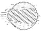
- FIG. 1Ais a cut-away perspective view of an eye 90 that illustrates an implanted ocular unit 100 according to some embodiments of the invention.
- FIG. 1Bis a side cross-section view of an eye 90 that illustrates an implanted ocular unit 100 , similar to FIG. 1A , according to some embodiments of the invention.
- FIG. 2Ais a side cross-section view of an eye 90 that illustrates an implanted intraocular unit 201 according to some embodiments of the invention.
- FIG. 2Bis a side cross-section view of an eye 90 that illustrates an implanted intraocular unit 202 according to some embodiments of the invention.
- FIG. 2Cis a side cross-section view of an eye 90 that illustrates an implanted intra-ocular unit 203 according to some embodiments of the invention.
- FIG. 2Dis a side cross-section view of an eye 90 that illustrates an implanted intra-ocular unit 204 having an embedded optical-fiber bundle, according to some embodiments of the invention.
- FIG. 3is a side cross-section view of an eye 90 that illustrates an implanted ocular unit 300 according to some embodiments of the invention.
- FIG. 4is a side cross-section view of an eye 90 that illustrates an implanted ocular unit 400 according to some embodiments of the invention.
- FIG. 5Ais a side cross-section view of an eye 90 that illustrates an implanted ocular unit 501 according to some embodiments of the invention.
- FIG. 5Bis a side cross-section view of an eye 90 that illustrates an implanted ocular unit 502 according to some embodiments of the invention.
- FIG. 5Cis a side cross-section view of an eye 90 that illustrates an implanted ocular unit 503 according to some embodiments of the invention.
- FIG. 6is a side cross-section view of an eye 90 that illustrates an implanted ocular unit 600 according to some embodiments of the invention.
- FIG. 7is a side cross-section view of a retina 97 .
- FIG. 8Ais a side cross-section view of a stimulation system 801 that uses a single-depth VCSEL array 887 and a holographic imager 811 .
- FIG. 8Bis a side cross-section view of a stimulation system 802 that uses a VCSEL array 888 having a plurality of depths and a holographic imager 812 .
- FIG. 9is a graph showing the absorption of light by PMMA at various wavelengths.
- FIG. 10is a graph showing two sets of measurements of the absorption of light by 0.5 mm of water at wavelengths of light between 1000 and 2100 nm (infrared).
- FIG. 11is a graph of a water absorption factor of light at wavelengths between 1.0 and 2.1 microns.
- FIG. 1Ais a cut-away perspective view of a nerve-stimulation system 101 for an eye 90 that illustrates an implanted ocular unit 100 , according to some embodiments of the invention.
- the ocular unit 100includes a light-transparent pathway or “image pipe” 110 (which includes an optional lens system 116 and a transparent body 111 ) for transmitting a stimulation pattern of infrared light 130 from an external stimulator array 180 through the eye 90 along optical path 199 , the ocular unit 100 having a light-receiving anterior end 112 closest to the eye's anterior surface and extending to a posterior end 114 of image pipe 110 closer to the fovea 96 than to the eye's anterior surface, transmitting light and/or projecting image 122 onto the retina 97 , including onto the macula 95 and fovea 96 .
- the curved anterior surface of image pipe 110acts as the anterior-end focussing element and no separately formed lens 116 is needed.
- an “image pipe”is an optical device that forms an image just beyond its posterior end (e.g., when an image pipe of the present invention is implanted in the eye, the image is formed on the nerves at the anterior surface of the retina) that is based on light 130 entering the anterior end.
- an image pipeincludes internal imaging components such as lenses, holographs, fiber optics or fiber-optic bundles, or the like, which assist in providing a focussed image at the retina.
- the image pipeis simply a transparent path that allows external imaging components to form the image on the nerves at the front surface of the retina. Because some embodiments of the present invention use single-wavelength infrared lasers, holographic imagers are well suited to form images through such an image pipe.
- the image pipe 110is substantially transparent to at least some infrared wavelengths of light between about 1000 nm and about 2000 nm, and in particular, is substantially transparent to those infrared wavelengths output by the source lasers of the stimulation apparatus.
- the image pipe 110has a substantially cylindrical shape such as shown in FIG. 1A , such that both ends of the image pipe 110 have substantially the same diameter.
- the image pipe 110is formed from a biocompatible-transparent-thermoplastic material such as poly(methyl methacrylate) (PMMA), or the like.
- PMMApoly(methyl methacrylate)
- the light-receiving anterior end 112 of ocular unit 100replaces at least a portion of the cornea 99 of the eye and thus forms part of the anterior surface of the eye.
- PMMAPoly(methyl methacrylate)
- PMMAis a transparent thermoplastic.
- PMMAhas been sold under many different names including Plexiglas®, Lucite® and Perspex®.
- PMMAis substantially transparent (i.e., a given thickness of about a centimeter or more passes a majority of incident light) to visible light (having wavelengths of 400 nm to 700 nm) and infrared light (IR) having wavelengths from about 700 nm to about 2800 nm.
- IRinfrared light
- Colored or tinted PMMA varietiesallow specific IR wavelengths to pass while blocking visible light and/or other IR wavelengths.
- ocular unit 100is surgically secured in place to the cornea 99 and/or sclera 98 in the eye with anchoring collar 140 and hydrogel skirt 150 .
- the implantis sewn (or stapled or otherwise anchored) to the ciliary muscle or secured to other internal parts of the eye to hold it securely in place.
- Ocular unit 100extends well into the vitreous humor 94 , which is less transparent than is image pipe 110 to certain infrared light wavelengths useful for nerve stimulation.
- the posterior end 114 of the image pipe 110is closer to the fovea than the front of the eye.
- image pipe 110has a length such that the posterior end 114 of the image pipe 110 is near the retina 97 in the region of the macula 95 and fovea 96 .
- the image pipe 110does not contact the retina 97 , in order to leave a pathway for the vitreous humor 94 to circulate and nourish the cells of the retina.
- the posterior end 114is positioned close enough to the retina 97 and fovea 96 such that the remaining vitreous humor is thin enough and transparent enough that infrared light output from the posterior end of the image pipe 110 will be sufficiently intense to cause retinal-nerve stimulation (i.e., triggering of nerve action potentials in the nerves of the retina due to impinging pulses of infrared light).
- retinal-nerve stimulationi.e., triggering of nerve action potentials in the nerves of the retina due to impinging pulses of infrared light.
- the ocular image pipe 110is solid material.
- PMMAhas a higher density than the vitreous humor.
- some embodiments of image pipe 110include at least one hollow portion such that the overall density of the image pipe 110 is the same as the density of the surrounding vitreous humor and the center of mass of the image pipe 110 coincides with the center of rotation of the eye, in order that the image pipe 110 does not tend to move relative to the eye with movement.
- the hollow portionis filled with an inert gas.
- the hollow portionis filled with a low-pressure gas having a pressure of no more than about 1000 Torr.
- the hollow portionis in the light path of the light path and at least one end of the hollow portion is shaped to form a lens to focus the infrared light on nerves of the retina.
- the placement, size, and shape of the hollow portion in the image pipe 110is used in some embodiments to not only match the density of the vitreous humor but to also control the center of gravity to help provide a more stable implant the is resistant to movement of the head or eyeball.
- the light-transmitting portion of image pipe 110is solid material and the hollow portion is formed in a peripheral portion outside and surrounding the light-transmitting path. This configuration reduces the number of optical interfaces in the light path.
- the light-transmitting portion of image pipe 110is solid material and the hollow portion is formed symmetrically around a peripheral portion outside and surrounding the light-transmitting path, such that regardless of whether the person's head is upright or is lying on one side, there is no rotational or other force acting to move the implant (i.e., image pipe 110 ) relative to the eye.
- the hollow portionis formed in (or is very slightly larger in) a top portion of image pipe 110 , in order to help keep the image pipe 110 upright and in the desired position when the patient's head is upright.
- one or both ends of the image pipe 110are shaped to focus the external stimulator light signals 130 on the retina and fovea.
- source 180includes a two-dimensional array of vertical-cavity surface-emitting lasers (VCSEL-array) that form an IR stimulator, which provides IR light 130 into the anterior end 112 of the ocular implant 100 .
- VCSEL-arrayvertical-cavity surface-emitting lasers
- the userhas an ocular unit 100 implanted in each eye, and the system provides there is a separate external two-dimensional array IR stimulator source 180 for each eye, wherein the two separate images help provide three-dimensional images to the brain through each eye's ocular unit 100 .
- image pipe 110includes a lens or lens system 116 , with a different index of refraction than the rest of image pipe 110 , to focus the image on the retina 97 .
- the lens system 116inverts the incoming image and focuses the image on the retina.
- the lens system 116is noninverting and directs diverging, collimated, or converging light on the nerve-tissue layer of the retina 97 .
- the image pipe 110 and its lens 116in combination with an external laser image-generation device 180 and its image processor(s) 182 and one or more cameras in camera system 181 , produce an infrared image on the retina, similar to the inverted optical-wavelength image a normal human eye. Since the human brain will automatically accustom itself to any image consistently formed on the retina whether or not the image is inverted, the camera system 181 , image processor 182 and stimulation light sources 180 can be configured to form the image as inverted or not according to the preferences of the user.
- camera system 181includes at least one camera directed toward the user's eye (e.g., to determine the locations of indicia 118 and/or 119 ) to determine the location and/or direction of movement of the gaze of the user, and this image of the eye (or of the indicia 118 / 119 ) is processed by image processor system 182 in order to control the position of the stimulation light sources that are generating the stimulation light signals 130 , in order to position the projected pattern of stimulation light onto the desired locations on retina 122 .
- the array of light sources 180themselves are physically moved to the desired position based on a detection of the position of the eye (e.g., a flat VCSEL array mounted on a gimbal and rotated on one or more axes by servos that are controlled by signals based on the detected eye position), while in other embodiments, different ones of the light sources 180 that are already in the desired positions relative to the eye are activated.
- eye-position sensorssuch as described in U.S. Pat. No. 4,720,189 issued to Heynen et al. on Jan. 19, 1988, titled “Eye-Position Sensor,” and U.S. Pat. No. 6,055,110 issued to Kintz et al. on Apr.
- a position of the eyee.g., the direction to which the eye is pointing and/or the distance between the eye and the stimulation-light projector 180
- a display positioning devicesuch as servo-controlled gimbals
- a focussing elementto maintain a focus of the IR-stimulation-light signals from stimulation-light projector 180 onto the desired nerve layer of the retina.
- a power source 183is operatively coupled to supply power to operate the camera system 181 , the image processor system 182 , and the stimulation light sources 180 .
- one or more grating light valvessuch as described in U.S. Pat. No. 7,177,081 titled “High Contrast Grating Light Valve Type Device,” which is incorporated herein by reference in its entirety
- one or more digital light projector devicessuch as described in U.S. Pat. No. 4,566,935 issued to Hornbeck on Jan. 28, 1986, titled “Spatial Light Modulator and Method,” or U.S. Pat. No.
- the ocular unit 100has at least one indicia mark to facilitate detection of the eye's position. In some embodiments, the ocular unit has at least one indicia mark 118 on the anterior end to facilitate external detection of the position of the eye and the pointing directions. In some embodiments, the ocular unit 100 has at least one indicia mark 119 on the posterior end to facilitate external detection of the position of the eye and the pointing directions. In some embodiments, one or more indicia marks are placed on both the anterior end posterior end, and/or on one or more other locations on the ocular unit 100 .
- the location and/or orientation of the implantis determined, for example, by obtaining an image of, or detecting reflected or fluorescent light from, the indicia mark or marks 118 and/or 119 and the external stimulator array signals are adjusted to compensate for the position of the eye (e.g., the image or pattern is moved such that the desired nerve tissue continues to be stimulated).
- an eye-position processor in the external image processor 182uses an “inward-pointing” camera in camera system 181 (i.e., a camera pointed toward the user to obtain an image of the eye and/or indicia 118 / 119 ) to detect movement or position of the user's eye(s), and generates control signals that direct an external camera view (i.e., the direction in which the camera system 181 is pointing, or if a very-wide-angle lens and/or multiple cameras are used, which of the images obtained by camera system 181 is used), providing a more realistic sensation of “looking around” to the user, instead of requiring movement of the user's entire head to obtain different images.
- an external camera viewi.e., the direction in which the camera system 181 is pointing, or if a very-wide-angle lens and/or multiple cameras are used, which of the images obtained by camera system 181 is used
- a plurality of “outward-pointing” camerasis included in camera system 181 (i.e., a plurality of cameras pointed toward different directions in the environment surrounding user to obtain a plurality of images from which to select based on the detected direction of the user's gaze).
- FIG. 1Bis a side cross-section view of an eye 90 that illustrates the implanted ocular unit 100 , which is also shown in FIG. 1A , according to some embodiments of the invention.
- the ocular unit 100includes a light-transparent pathway or “image pipe” 110 for transmitting a stimulation pattern of infrared light from an external stimulator array through the eye, and a fastening mechanism (e.g., anchoring collar 140 and hydrogel skirt 150 ) for attaching the ocular unit 100 to the eye 90 .
- the image pipe 110has a light-receiving anterior end 112 closest to the eye's anterior surface and extending to a posterior end 114 of image pipe 110 closer to the fovea 96 than to the eye's anterior surface.
- the posterior end 114 of image pipe 110(and in some embodiments of the ocular units of FIGS. 2A , 2 B, 3 , 4 , 5 , and 6 , the respective posterior ends of their image pipes) is within about 10 mm of the retina. In some embodiments, the posterior end of the image pipe is within about 8 mm of the retina. In some embodiments, the posterior end of the image pipe is within about 5 mm of the retina. In some embodiments, the posterior end of the image pipe is within about 4 mm of the retina. In some embodiments, the posterior end of image the pipe is within about 3 mm of the retina.
- the posterior end of image the pipeis within about 2 mm of the retina. In some embodiments, the posterior end of image the pipe is within about 1 mm of the retina. In some embodiments, the posterior end of image the pipe is between about 1 cm and about 5 mm of the retina. In some embodiments, the posterior end of the image pipe is between about 5 mm and about 2 mm of the retina. In some embodiments of the ocular units of FIGS. 1A , 1 B, 2 A, 2 B, 3 , 4 , 5 , and 6 , the light path within the ocular unit is at least 50% of the total distance from the anterior surface of the eye to the retina. In some embodiments of the ocular units of FIGS.
- the light path within the ocular unitis at least 70% of the total distance from the anterior surface of the eye to the retina. In some embodiments of the ocular units of FIGS. 1A , 1 B, 2 A, 2 B, 3 , 4 , 5 , and 6 , the light path within the ocular unit is at least 80% of the total distance from the anterior surface of the eye to the retina. In some embodiments of the ocular units of FIGS. 1A , 1 B, 2 A, 2 B, 3 , 4 , 5 , and 6 , the light path within the ocular unit is at least 90% of the total distance from the anterior surface of the eye to the retina.
- the light path within the ocular unitis at least 95% of the total distance from the anterior surface of the eye to the retina.
- the entire systemincluding exterior optics in the stimulation light source 180 , along with the lens system 116 and body 110 of ocular unit 100 that act together to focus the image onto the desired nerve-tissue layer of the retina 97 .
- FIG. 2Ais a side cross-section view of an eye 90 that illustrates an implanted intra-ocular unit 201 according to some embodiments of the invention.
- ocular unit 201is similar to ocular unit 100 except ocular unit 201 is fully contained intraocularly (i.e., completely inside the eye) after being surgically implanted.
- the image pipe 210is surgically secured in place in the eye with the implant sewn, stapled, or otherwise secured 245 to the ciliary muscle 93 or secured to other internal parts of the eye to hold it securely in place.
- the ocular unit 201is completely contained within the eye and the user's cornea 99 is maintained intact.
- the ocular unit 201includes an image pipe 210 for transmitting a stimulation pattern of infrared light from an external stimulator array through the eye, the ocular unit 201 having a light-receiving anterior end 212 closest to the eye's anterior surface (behind the cornea) and extending to a posterior end 214 that is closer to the fovea than to the eye's anterior surface.
- the image pipe 210is substantially transparent to at least some infrared wavelengths of light between about 1000 nm and about 2000 nm.
- the image pipe 210is substantially cylindrical-shaped such as shown in FIG. 2 , such that both ends of the image pipe 210 have substantially the same diameter.
- the image pipe 210is formed from a biocompatible-transparent-thermoplastic material such as poly(methyl methacrylate) (PMMA), or the like.
- the posterior end 214 of the image pipe 210is closer to the fovea than the front of the eye.
- image pipe 210has a length such that the posterior end 214 of the image pipe 210 is near the retina 97 in the region of the fovea 96 .
- the image pipe 210does not contact the retina, in order to leave a pathway for the vitreous humor of the eye to circulate and nourish the cells of the retina.
- the posterior end 214is positioned close enough to the retina 97 and fovea 96 such that the remaining vitreous humor 94 is thin enough and transparent enough that infrared light output from the posterior end of the image pipe 210 will be sufficiently intense to cause retinal-nerve stimulation (i.e., triggering of nerve action potentials in the nerves of the retina due to impinging pulses of infrared light).
- retinal-nerve stimulationi.e., triggering of nerve action potentials in the nerves of the retina due to impinging pulses of infrared light.
- the ocular image pipe 210is solid material.
- PMMAhas a higher density than the vitreous humor.
- some embodiments of image pipe 210include at least one hollow portion such that the overall density of the image pipe 210 is the same as the density of the surrounding vitreous humor and the center of mass of the image pipe coincides with the center of rotation of the eye, in order that the image pipe 210 does not tend to move relative to the eye with movement.
- the hollow portionis filled with an inert gas.
- the hollow portionis filled with a low-pressure gas having a pressure of no more than about 1000 Torr.
- the hollow portionis in the light path of the light path and at least one end of the hollow portion is shaped to form a lens to focus the infrared light on nerves of the retina.
- the placement, size, and shape of the hollow portion in the image pipe 210is used in some embodiments to not only match the density of the vitreous humor but to also control the center of gravity to help provide a more stable implant the is resistant to movement of the head or eyeball.
- the light-transmitting portion of image pipe 210is solid material and the hollow portion is formed in a peripheral portion outside and surrounding the light-transmitting path. This configuration reduces the number of optical interfaces in the light path.
- the light-transmitting portion of image pipe 210is solid material and the hollow portion is formed symmetrically around a peripheral portion outside and surrounding the light-transmitting path, such that regardless of whether the person's head is upright or is lying on one side, there is no rotational or other force acting to move the implant (i.e., image pipe 210 ) relative to the eye.
- the hollow portionis formed in (or is very slightly larger in) a top portion of image pipe 210 , in order to help keep the image pipe 210 upright and in the desired position when the patient's head is upright.
- one or both ends of the image pipe 210are shaped to focus the externally generated stimulator-array signals on the retina and fovea.
- the present inventionincludes an external two-dimensional array VCSEL-array IR stimulator providing IR light 130 into the anterior end of the ocular implant 201 .
- IR light sourcesare used, such as LED array emitters, or one or more single IR light sources that project light to an array modulator such as one or more grating light valves (for example, as described in U.S. Pat. No. 7,177,081 titled “High Contrast Grating Light Valve Type Device,” which is incorporated herein by reference in its entirety) and/or one or more digital light projector devices (such as described in U.S. Pat. No. 4,566,935 issued to Hornbeck on Jan. 28, 1986, titled “Spatial light modulator and method,” or U.S. Pat. No.
- any other suitable sources of IR stimulation lightare used, including light sources emitting from a plurality of heights from their substrates (such as LED arrays or MEMS mirrors configured to focus at a plurality of depths in the nerves of the retina, such as shown in FIG. 8B ).
- image pipe 210includes a lens 216 , with a different index of refraction than the rest of image pipe 210 , to focus the image on the retina 97 .
- the lens 216is a convex lens that has a higher index of refraction than the surrounding tissue and/or the body 210 of ocular unit 201 (or is a concave lens that has a lower index of refraction) and lens 216 (along with any external lens(es) and the cornea 99 ) inverts the incoming image and focuses the image on the retina. Note that in some embodiments, it is the entire system including exterior optics in the light source 180 and the cornea of the eye, along with the lens system 216 that act together to focus the image onto the desired nerve tissue. In some other embodiments, on the lens is noninverting and directs collimated light on the retina. In some embodiments, the image pipe 210 , lens 216 , in combination with an external laser-signal generation device produce an inverted nerve-stimulation pattern on the retina, similar to the inverted image a normal human eye.
- the ocular unit 201has at least one indicia mark 218 , 219 , and/or 220 to facilitate detection of the eye's position.
- the ocular unithas at least one anterior indicia mark 118 , posterior indicia mark 119 , or both to facilitate external detection of the position of the eye and the pointing direction of the gaze used for controlling the camera system 181 (e.g., moving the position/direction of the camera 181 , or shifting the portion of the image obtained from the camera 181 and used to generation the stimulation signals 130 ).
- indicia marksare placed on one or more other locations on the ocular unit 100 .
- reflected light from the indicia mark or marksis detected and the external stimulator array signals are adjusted to compensate for the position of the eye.
- FIG. 2Bis a side cross-section view of an eye 90 that illustrates an implanted intra-ocular unit 202 according to some embodiments of the invention.
- the lens 217is a concave lens that has a higher index of refraction than the surrounding tissue and/or the body 210 of ocular unit 201 (or is a convex lens that has a lower index of refraction) and does not invert the incoming image in order to project the image on the nerves in the anterior surface of the retina. Note that in some embodiments, it is the entire system including exterior optics in the light source 180 and the cornea of the eye, along with the lens system 217 that act together to focus the image onto the desired nerve tissue.
- FIG. 2Cis a side cross-section view of an eye 90 that illustrates an implanted intra-ocular unit 203 according to some embodiments of the invention.
- ocular unit 203is identical to ocular unit 201 of FIG. 2A , except for including one or more bubbles or air-filled pockets 222 , located outside of the optical path 199 (e.g., in some embodiments, along side of the focal point of the light focussed by lens 216 ) and used to provide a neutral buoyancy to ocular unit 203 , so it neither floats toward the top of the eye 90 , nor sinks toward the bottom of the eye 90 , nor twists (e.g., up in back and down in front due to the different material densities of the lens 216 and body 210 ).
- pockets 222are coated with an opaque material, in order that they serve as an aperture or spatial filter, blocking light that is not part of the focussed stimulation-light image.
- pockets 222have one or more indicia 220 located such that an external camera can image the indicia and then determine the position of the eye 90 , but also located off to the side of the optical path 199 such that the indicia do not interfere with or block any portion of the projected image of the stimulation light.
- pockets 222are formed of two or more separate bubbles located so as to provide a center of gravity point and neutral buoyancy to minimize unwanted movement of the ocular unit 203 , while in other embodiments, a torus-shaped pocket surrounds a center portion of body 210 to provide this functionality. Further descriptions of such structures are provided below in the description of FIG. 4 .
- an aperture that is not part of such bubble featuresis provided in any of the embodiments described herein, where the aperture surrounds the expected focal point of the image light, to serve as a spatial filter, blocking light that is not part of the focussed stimulation-light image.
- FIG. 2Dis a side cross-section view of an eye 90 that illustrates an implanted intra-ocular unit 204 having an embedded optical-fiber bundle, according to some embodiments of the invention.
- the body of the intraocular unit 242includes a plurality of optical fibers 244 embedded in a carrier 243 of PMMA 243 .
- Each optical fiber 244provides a separate optical path 199 through the intraocular unit 242 .
- the plurality of optical fibers 244are arranged in an array that preserves the image aspect ratio.
- An image from the light source 130is formed on the anterior end 212 of the intraocular implant, the image is conducted through the optical fibers 244 , and the image is projected from the posterior end 214 of the ocular implant onto the retinal nerves.
- the optical fibers 244are substantially parallel (e.g., the output image exiting the posterior end 214 is the same size and shape as the input image entering at anterior end 212 ).
- the optical fibers 244have varying non-parallel paths through the carrier 243 (e.g., in some embodiments, the optical fibers 244 themselves remain a constant-diameter size but their spacings increase towards the posterior end such that the fibers diverge (gradually separate from one another towards the posterior end 214 ) such that the height and/or width of the output image exiting the posterior end 214 is larger than the input image entering at anterior end 212 , while in other embodiments, in some embodiments, the optical fibers converge (gradually get closer to one another) such that output image exiting the posterior end 214 is smaller than the input image entering at anterior end 212 ).
- a plurality of optical fibers 244is gathered in a tight bundle, then one end is heated and stretched away from the opposite end such that the stretched end becomes smaller in diameter while preserving the aspect ratio of the image that is transmitted through the bundle, but the size changes (becoming larger or smaller depending on which end the image enters), since the diameter of each fiber changes, and the diameter of the bundle as a whole changes.
- the body 242 of the intraocular implantis shaped substantially like a cylinder.
- the body 242 of the intraocular implanthas a substantially conical shape wherein the posterior end 214 of the body 242 has a larger diameter than the anterior end 212 of the body 242 .
- the body 242 of the intraocular implanthas a substantially conical shape wherein the anterior end 212 of the body 242 has a larger diameter than the posterior end 214 of the body 242 .
- the optical fibers 244are glass and are fabricated from a material that is substantially transparent (transmits at least about 50% of the light energy) to wavelengths of light in the infrared region of about 1000 nm to about 2100 nm (or at least in the portion of that infrared spectrum that is used by the stimulation light signal). In some embodiments, the optical fibers 244 are fabricated from a material that is substantially transparent (transmits at least about 50% of the light energy) to wavelengths of light in the infrared region of about 1600 nm to about 2000 nm.
- the optical fibers 244are fabricated from a material that is substantially transparent to wavelengths of light in the infrared region of about 1700 nm to about 1900 nm. In some embodiments, the optical fibers 244 are fabricated from a material that is substantially transparent to wavelengths of light in the infrared region of about 1800 nm to about 2000 nm. In some embodiments, the optical fibers 244 are fabricated from a material that is substantially transparent to wavelengths of light in the infrared region of about 1800 nm to about 1900 nm.
- FIG. 3is a side cross-section view of an eye 90 that illustrates an implanted ocular unit 300 according to some embodiments of the invention.
- the ocular unit 300includes image pipe 310 that has a substantially conical, or tapered, shape rather than the cylindrical shape (e.g., as shown in ocular unit 100 in FIGS. 1A and 1B and ocular unit 201 in FIG. 2A and ocular unit 202 of FIG. 2B ) in order to provide stimulating light over a larger area of the retina for a wider field of view.
- the posterior end 314 of the transparent material of image pipe 310has a diameter that is larger than a diameter of the anterior end 312 of the transparent material.
- the ocular unit 300includes a light-transparent pathway or “image pipe” 310 for transmitting a stimulation pattern of infrared light 130 from an external stimulator array through the eye, the ocular unit 300 having a light-receiving anterior end 312 closest to the eye's anterior surface and extending to a posterior end 314 of image pipe 310 closer to the fovea 96 than to the eye's anterior surface, projecting an image on the retina 97 , including on the macula 95 and fovea 96 .
- one or both ends of the image pipe 310are shaped to focus the externally generated stimulator-array signals on the retina and fovea.
- there is an external two-dimensional array IR stimulator for each eyeto help provide three-dimensional images to the user with an ocular unit 300 implanted in each eye.
- image pipe 310includes a lens (see, for example, lens 216 of FIG. 2A ) with a different index of refraction than the rest of image pipe 310 , to focus the image on the retina 97 .
- the lensinverts the incoming image and focuses the image on the retina. In some other embodiments, on the lens is noninverting and directs collimated light on the retina. In some embodiments, the image pipe 310 , lens, in combination with an external laser-signal generation device produce an inverted nerve-stimulation pattern on the retina, similar to the inverted image a normal human eye.
- ocular unit 300has the optional features of ocular unit 100 and intra-ocular unit 201 , with the difference being the conical-shaped image pipe 310 .
- ocular unit 201includes a conical-shaped image pipe instead of the cylindrically shaped image pipe 210 shown in FIG. 2A and FIG. 2B .
- FIG. 4is a side cross-section view of an eye 90 that illustrates an implanted ocular unit 400 according to some embodiments of the invention.
- the ocular unit 400includes image pipe 410 that has a substantially cylindrical shape with an additional widened section including a doughnut-shaped (i.e., torus-shaped) hollow portion 422 that surrounds the longitudinal axis of the optical path 199 .
- the posterior end 414 of the transparent material of image pipe 410has a diameter about the same diameter as the anterior end 412 of the transparent material.
- the ocular unit 400includes a light-transparent pathway or “image pipe” 410 for transmitting a stimulation pattern of infrared light 130 from an external stimulator array through the eye, the ocular unit 400 having a light-receiving anterior end 412 closest to the eye's anterior surface and extending to a posterior end 414 of image pipe 410 closer to the fovea 96 than to the eye's anterior surface, projecting an image on the retina 97 , including on the macula 95 and fovea 96 .
- image pipe 410include at least one hollow portion 422 such that the overall density of the image pipe 410 is the same as the density of the surrounding vitreous humor and the center of mass of the image pipe 410 coincides with the center of rotation of the eye, in order that the image pipe 410 does not tend to move relative to the eye with movement.
- the hollow portion 422is filled with an inert gas.
- the hollow portionis filled with a low-pressure gas having a pressure of no more than about 1000 Torr.
- the placement, size, and shape of the hollow portion in the image pipe 410is used in some embodiments to not only match the density of the vitreous humor but to also control the center of gravity to help provide a more stable implant the is resistant to movement of the head or eyeball.
- the light-transmitting portion of image pipe 410is solid material and the hollow portion is formed in a peripheral portion outside and surrounding the light-transmitting path. This configuration reduces the number of optical interfaces in the light path.
- the light-transmitting portion of image pipe 410is solid material and the hollow portion 422 is formed symmetrically around a peripheral portion outside and surrounding the light-transmitting path, such that regardless of whether the person's head is upright or is lying on one side, there is no rotational or other force acting to move the implant (i.e., image pipe 410 ) relative to the eye.
- the hollow portionis formed in (or is very slightly larger in) a top portion of image pipe 410 , in order to help keep the image pipe 410 upright and in the desired position when the patient's head is upright.
- image pipe 410includes a lens 416 , with a different index of refraction than the rest of image pipe 410 , to focus the image on the retina 97 .
- the lensinverts the incoming image and focuses the image through a focal point and onto the retina.
- the lens 416is noninverting and directs collimated light on the retina.
- the lensis noninverting and directs diverging light (such as the lens 217 shown in FIG. 2B ), or converging light (embodiments not shown herein) on the retina.
- the image pipe 410 , lens 416in combination with an external laser-signal generation device produce an inverted nerve-stimulation pattern on the retina, similar to the inverted image a normal human eye.
- ocular unit 400is fully contained intraocularly (i.e., completely inside the eye similar to ocular unit 201 of FIG. 2A ) after being surgically implanted.
- the image pipe 410is surgically secured in place in the eye with the implant sewn, stapled, or otherwise secured to the ciliary muscle or secured to other internal parts of the eye to hold it securely in place.
- the ocular unit 400is completely contained within the eye and the user's cornea 99 is maintained intact.
- FIG. 5Ais a side cross-section view of an eye 90 that illustrates an implanted ocular unit 501 according to some embodiments of the invention.
- the ocular unit 501includes image pipe 510 that has a substantially cylindrical shape with a short hollow center portion 522 A.
- the posterior end 514 of the transparent material of image pipe 510has a diameter about the same diameter as the anterior end 512 of the transparent material.
- the ocular unit 501includes a light-transparent pathway or “image pipe” 510 for transmitting a stimulation pattern of infrared light 130 from an external stimulator array through the eye, the ocular unit 501 having a light-receiving anterior end 512 closest to the eye's anterior surface and extending to a posterior end 514 of image pipe 510 closer to the fovea 96 than to the eye's anterior surface, projecting an image on the retina 97 , including on the macula 95 and fovea 96 .
- image pipe 510include at least one hollow portion 522 A such that the overall density of the image pipe 510 is the same as the density of the surrounding vitreous humor and the center of mass of the image pipe 510 coincides with the center of rotation of the eye, in order that the image pipe 510 does not tend to move relative to the eye with movement.
- the hollow portion 522 Ais filled with an inert gas.
- the hollow portion 522 Ais filled with a low-pressure gas having a pressure of no more than about 1000 Torr.
- the placement, size, and shape of the hollow portion 522 A in the image pipe 510is used in some embodiments to not only match the density of the vitreous humor but to also control the center of gravity (e.g., to balance relative to the mass of lens 516 ) to help provide a more stable implant the is resistant to movement of the head or eyeball.
- the light-transmitting portion of image pipe 510is solid material and the hollow portion is formed in a central portion of the light-transmitting path.
- the hollow portionis formed in (or is very slightly larger in) a top portion of image pipe 110 , in order to help keep the image pipe 510 upright and in the desired position when the patient's head is upright.
- image pipe 510includes a lens 516 , with a different index of refraction than the rest of image pipe 510 , to focus the image on the retina 97 .
- the lensinverts the incoming image and focuses the image on the retina.
- on the lensis noninverting and directs collimated light on the retina.
- the image pipe 510 , lens 516 , in combination with an external laser-signal generation device 180produce an inverted nerve-stimulation pattern on the retina, similar to the inverted image a normal human eye.
- ocular unit 501is fully contained intraocularly (i.e., completely inside the eye similar to ocular unit 201 ) after being surgically implanted.
- the image pipe 510is surgically secured in place in the eye with the implant sewn, stapled, or otherwise secured to the ciliary muscle or secured to other internal parts of the eye to hold it securely in place.
- the ocular unit 501is completely contained within the eye and the user's cornea 99 is maintained intact.
- FIG. 5Bis a side cross-section view of an eye 90 that illustrates an implanted ocular unit 502 according to some embodiments of the invention.
- the ocular unit 502includes image pipe 510 that has a substantially cylindrical shape with a long hollow center portion 522 B.
- implanted ocular unit 502is substantially similar to ocular unit 501 of FIG. 5A described above, except that ocular unit 502 has a longer hollow center portion 522 B.
- FIG. 5Cis a side cross-section view of an eye 90 that illustrates an implanted ocular unit 503 according to some embodiments of the invention.
- the ocular unit 503includes image pipe 510 that has a substantially cylindrical shape with a long hollow center portion 522 B.
- implanted ocular unit 503is substantially similar to ocular unit 502 of FIG. 5B , except that ocular unit 503 is implanted entirely within the eye 90 as was the case with ocular unit 203 of FIG. 2C described above.
- FIG. 6is a side cross-section view of an eye 90 that illustrates an implanted ocular unit 600 according to some embodiments of the invention.
- the ocular unit 600includes image pipe 610 that has a substantially conical shape with an additional widened section including a doughnut-shaped hollow portion 622 .
- the posterior end 614 of the transparent material of image pipe 610has a diameter substantially larger than the diameter as the anterior end 612 of the transparent material.
- the ocular unit 600includes a light-transparent pathway or “image pipe” 610 for transmitting a stimulation pattern of infrared light 130 from an external stimulator array through the eye, the ocular unit 600 having a light-receiving anterior end 612 closest to the eye's anterior surface and extending to a posterior end 614 of image pipe 610 closer to the fovea 96 than to the eye's anterior surface, projecting an image on the retina 97 , including on the macula 95 and fovea 96 .
- image pipe 610include at least one hollow portion 622 such that the overall density of the image pipe 610 is the same as the density of the surrounding vitreous humor and the center of mass of the image pipe 610 coincides with the center of rotation of the eye, in order that the image pipe 610 does not tend to move relative to the eye with movement.
- the hollow portion 622is filled with an inert gas.
- the hollow portionis filled with a low-pressure gas having a pressure of no more than about 1000 Torr.
- the placement, size, and shape of the hollow portion in the image pipe 610is used in some embodiments to not only match the density of the vitreous humor but to also control the center of gravity to help provide a more stable implant the is resistant to movement of the head or eyeball.
- the light-transmitting portion of image pipe 610is solid material and the hollow portion is formed in a peripheral portion outside and surrounding the light-transmitting path. This configuration reduces the number of optical interfaces in the light path.
- the light-transmitting portion of image pipe 610is solid material and the hollow portion 422 is formed symmetrically around a peripheral portion outside and surrounding the light-transmitting path, such that regardless of whether the person's head is upright or is lying on one side, there is no rotational or other force acting to move the implant (i.e., image pipe 610 ) relative to the eye.
- the hollow portionis formed in (or is very slightly larger in) a top portion of image pipe 610 , in order to help keep the image pipe 610 upright and in the desired position when the patient's head is upright.
- image pipe 610includes a lens (see, for example, lens 216 of FIG. 2A ) with a different index of refraction than the rest of image pipe 610 , to focus the image on the retina 97 .
- the lensinverts the incoming image and focuses the image on the retina.
- on the lensis noninverting and directs collimated light on the retina.
- the image pipe 610 , lens, in combination with an external laser-signal generation deviceproduce an inverted nerve-stimulation pattern on the retina, similar to the inverted image a normal human eye.
- ocular unit 600is fully contained intraocularly (i.e., completely inside the eye similar to ocular unit 600 ) after being surgically implanted.
- the image pipe 610is surgically secured in place in the eye with the implant sewn, stapled, or otherwise secured to the ciliary muscle or secured to other internal parts of the eye to hold it securely in place.
- the ocular unit 600is completely contained within the eye and the user's cornea 99 is maintained intact.
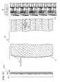
- FIG. 7is a side cross-section view of a retina 97 .
- the present inventionis used to stimulate nerve action potentials directly in the ganglion nerves 85 , the amacrine nerve cells 83 , and/or the bipolar nerve cells 82 of the retina 97 .
- the rod cells and cone cells 81 at the posterior wall 80 of the retina 97receive visible light (having wavelengths in the range of 400 to 700 nm), and generate nerve signals to a plurality of synapses at the tips of its axons.
- bipolar cells 82 and amacrine cells 83that are in direct contact with the synapses of that rod or cone cell 81 .
- bipolar cells 82generate excitory signals based on inputs from the rods and cones to which each bipolar cell is connected, while the amacrine cells generate inhibitory signals based on inputs from the rods and cones to which each amacrine cell is connected.
- connection layersthere are a plurality of connection layers in the inner plexiform layer 84 , wherein at each connection layer has transmit ends of axons from various excitory bipolar cells and inhibitory amacrine cells, to which are connected the receive ends of the ganglion cells.
- different signals from the IR stimulation lightare focussed on different ones of either ganglion, amacrine, or bipolar cells.
- the IR stimulation light signalsWhen focussed on the ganglion layer of cells 85 , the IR stimulation light signals generate nerve action potentials (NAPs) directly in ones of those ganglion cells, which NAPs are then transmitted toward the optic nerve output of the eye.
- NAPsnerve action potentials
- the IR stimulation light signalsWhen focussed on the bipolar layer of cells 82 , the IR stimulation light signals generate excitory nerve action potentials (NAPs) directly in ones of those bipolar cells, which excitory NAPs are then transmitted toward one of the layers of interconnects in the inner plexiform layer 84 , where once they combine and reach a certain threshold they then trigger a NAP in the respective ganglion cell(s).
- NAPsexcitory nerve action potentials
- the IR stimulation light signalswhen focussed on the amacrine layer of cells 83 , the IR stimulation light signals generate inhibitory nerve action potentials (NAPs) directly in ones of those amacrine cells, which inhibitory NAPs are then transmitted toward one of the layers of interconnects in the inner plexiform layer 84 , where once they act to inhibit NAP in the respective ganglion cell(s).
- the stimulation light signalsare transmitted from differing distances from the anterior (light-entry) end of the ocular implant, and thus they focus at differing distances from the posterior end of the ocular implant, and thus can be controlled as to which layer of nerve cells they will stimulate.
- NAPscan be controllably and selectively triggered in different layers of nerve cells in the retina, to thus generate NAPs that are either excitory (from the bipolar cell layer 82 ) or inhibitory (from the amacrine layer of cells 83 ) and those NAPS are then additively and/or subtractively combined in the inner plexiform layer to trigger output signals in the ganglion cells connected to those inner plexiform layer connections, or directly output (from the ganglion layer of cells 85 ) when the stimulation light is focussed there.
- the external stimulation IR sourceoutputs IR light signals that represent a pre-processed version of an image scene, wherein the preprocessing mimics or replicates the internal optical processing of images normally performed by the millions of interconnections between the various cell layers of the retina.
- the preprocessing neededis empirically determined by focussing various patterns on different ones of the cells in the various bipolar, amacrine and/or ganglion layers and having the subjects report the sensation perceived, and/or by actually measuring NAPs in the tissue of eyes of lab subjects.
- NAPs in the various nerve-cell layers 82 , 83 , and/or 85certain degeneration effects, defects or diseases that cause loss of vision can be bypassed by triggering NAPs in the anterior layers of cells of the retina.
- the IR stimulation lightis used to trigger NAPs in the rods or cones, and those NAPs are then combined in the normal way of processing by the various bipolar, amacrine and/or ganglion layers.
- FIG. 8Ais a side cross-section view of a stimulation system 801 that uses a single-depth VCSEL array 887 and a holographic imager 811 .
- the stimulation light 130 emitted by the stimulation light sourcese.g., in some embodiments, an array of independently addressable and separately activatable vertical-cavity surface-emitting lasers (VCSELs) 885 (optionally each including a focussing element 886 such as a lens or holograph) implemented on one or more semiconductor chips 887 is of a narrow-linewidth single wavelength laser light. This single wavelength light facilitates focussing using holographs.
- a holograph 811is implemented on the anterior surface 112 of ocular unit 801 .
- holograph 811facilitates focussing the stimulation light at different layers (e.g., various nerve-cell layers 82 , 83 , and/or 85 and/or the cone/rod cells of optical-cell layer 81 ) of the retina 97 .
- all of the VCSELs 85are implemented at a single depth (as a single plane of emission at the surface of chip 887 ).
- holograph 811is created by doing a numerical simulation of the light sources at the surface plane of the VCSEL array chip 887 and a plurality of layers at different depths in the retina, in order that various light source points can be activated to trigger NAPs at selected layers (e.g., cell layers 81 , 82 , 83 , and/or 85 ) and selected Cartesian coordinates on the retina 97 (i.e., at the three-dimensional coordinate of the desired cells to be stimulated).
- selected layerse.g., cell layers 81 , 82 , 83 , and/or 85
- selected Cartesian coordinates on the retina 97i.e., at the three-dimensional coordinate of the desired cells to be stimulated.
- FIG. 8Bis a side cross-section view of a stimulation system 802 that uses a VCSEL array 888 having a plurality of depths and a holographic imager 812 .
- the VCSELs 85are implemented at a plurality of depths (as a plurality of planes of emission at the surface of chip 887 ).
- the ocular unit's focussing elemente.g., lens 116 of FIG. 1A or holograph 812 of FIG.
- the 8Bcan focus the light from the different emission planes onto different layers of cells (e.g., the ganglion nerve cells 85 , the amacrine nerve cells 83 , and/or the bipolar nerve cells 82 , and/or the cone/rod cells of optical-wavelength-detecting cell layer 81 ) in the retina 97 .
- cellse.g., the ganglion nerve cells 85 , the amacrine nerve cells 83 , and/or the bipolar nerve cells 82 , and/or the cone/rod cells of optical-wavelength-detecting cell layer 81
- holograph 812is created by doing a numerical simulation of the light sources at the plurality of emission planes of the VCSEL array chip 887 and a plurality of layers at different depths in the retina, in order that various light source points can be activated to trigger NAPs at selected layers (e.g., cell layers 81 , 82 , 83 , and/or 85 ) and selected Cartesian coordinates on the retina 97 (i.e., at the three-dimensional coordinate of the desired cells to be stimulated).
- selected layerse.g., cell layers 81 , 82 , 83 , and/or 85
- selected Cartesian coordinates on the retina 97i.e., at the three-dimensional coordinate of the desired cells to be stimulated.
- FIG. 9is a graph that shows the transmittance of light with wavelengths of 0.5 microns to 2.5 microns through a typical commercially available acrylic (PMMA) material.
- PMMAacrylic
- This specific datais from a one-eighth-inch (3.17 mm)-thick piece of an acrylic (PMMA) product available from Fresnel Technologies, Inc. in Fort Worth, Tex. It can be seen that the amount of light transmitted through the PMMA material varies considerably with the wavelength of light, from 90 percent or more transmitted at shorter wavelengths (e.g., less than 1.2-micron wavelengths) to almost none at some longer wavelengths (e.g., greater than 2.2-micron wavelengths).
- a polymer materialis used that has a relatively high transmittance at the wavelengths used by the present invention (greater than 50% of the incident light is transmitted out the posterior end).
- a polymer materialsuch as PMMA having a high biocompatibility is used as an outer layer or coating on the ocular implant, and a different material (such as glass or another polymer) is used for most of the light-transmission path in the case where the coating material is not transparent enough at the wavelengths used, or where the coating material has a density (mass-per-volume) that is different than what is wanted (e.g., a density that matches the density of the fluids in the eye).
- a densitymass-per-volume
- FIG. 10is a graph showing the absorption of light with various wavelengths in a range of 1000 nm to 2100 nm (output intensity as a percent of the input intensity) for a 0.5-mm-thick layer of water.
- the amount of light transmitted though watervaries considerably over this range of light wavelengths, with multiple peaks of absorption.
- the vitreous humor of an eyeis 98-99% water, so this graph, showing the absorption by water, approximates the absorption of various wavelengths of infrared light in vitreous humor.
- Neurons that make up the retina of an eyecan be directly stimulated by light such that NAPs or CNAPs are triggered.
- the NAP or CNAP response of the neuronsdepends on the energy (power times pulse duration) absorbed per unit area and wavelength (absorption by various tissues varies as a function of wavelength) of the light pulses impinging on and thereby directly stimulating the neurons.
- Neuronsare sensitive to wavelengths of light in the range of about 1800 nm to about 1900 nm.
- FIG. 9illustrates that PMMA has a relatively high transmittance in most of this wavelength range so it is a good choice of material for transmitting infrared light from an external light source to the retinal nerves of an eye, in some embodiments.
- FIG. 9illustrates that PMMA has a relatively high transmittance in most of this wavelength range so it is a good choice of material for transmitting infrared light from an external light source to the retinal nerves of an eye, in some embodiments.
- FIG. 9illustrates that P
- FIG. 10shows that water (and thus vitreous humor) has very high light absorption for wavelengths longer than 1900 nm, and relatively high absorption in much of the wavelength range of between about 1800 nm to about 1900 nm.
- some embodiments of the present inventionuse wavelengths that represent a compromise between wavelengths that are readily absorbed by the nerves to trigger a NAP response, and those that readily pass through the thin layer of vitreous humor at the posterior end of the ocular implant and/or the thin layer of aqueous humor at the anterior end. Locating the respective ends of the intraocular implant close to the front and rear surfaces of an eye results in greater light signal transmission from the external light to the retinal nerves, but benefits from more precisely manufactured components and a more complex surgical implant procedure needed to get a close fit.
- locating the ends of the intraocular implant further from the front and rear surfaces of the eyeresults in the need for less precisely manufactured components and requires a less complex surgical implant process, and it may be biologically beneficial to increase the fluid adjacent the tissue, but results in a decreased amount of signal light transmitted from the external light source to the retinal nerves of the eye.
- the light-receiving surface portion of the anterior end 212 of the ocular unit(according to any of the above-described embodiments of the present invention) is shaped so as to have a substantially constant spacing from (i.e., to substantially conform to) the inner surface of the cornea of the eye.
- this light-receiving surface portion of the anterior end of the ocular unitis located at a substantially constant spacing of no more than 2.5 mm from the inner surface of the cornea of the eye. In some embodiments, this light-receiving anterior surface portion is located at a substantially constant spacing of no more than 2.0 mm from the inner surface of the cornea of the eye. In some embodiments, this light-receiving anterior surface portion is located at a substantially constant spacing of no more than 1.5 mm from the inner surface of the cornea of the eye. In some embodiments, this light-receiving anterior surface portion is located at a substantially constant spacing of no more than 1.0 mm from the inner surface of the cornea of the eye.
- this light-receiving anterior surface portionis located at a substantially constant spacing of no more than 0.5 mm from the inner surface of the cornea of the eye. In some embodiments, this light-receiving anterior surface portion is located no more than 0.2 mm from the inner surface of the cornea of the eye. In some embodiments, this light-receiving anterior surface portion is located at a substantially constant spacing of about 0.5 mm from the inner surface of the cornea of the eye. In some embodiments, this light-receiving anterior surface portion is located at a substantially constant spacing of about 0.2 mm from the inner surface of the cornea of the eye.
- the light-output surface portion of posterior end 214 of the ocular unit(according to any of the above-described embodiments of the present invention) is shaped so as to have a substantially constant spacing from (i.e., to substantially conform to) the ganglion layer of the retina of the eye.
- the light-output surface portion of posterior end of the ocular unitis located at a substantially constant spacing of no more than 2.5 mm from the ganglion layer of the retina of the eye. In some embodiments, this light-output surface portion is located at a substantially constant spacing of no more than 2.0 mm from the ganglion layer of the retina of the eye. In some embodiments, this light-output surface portion is located at a substantially constant spacing of no more than 1.5 mm from the ganglion layer of the retina of the eye. In some embodiments, this light-output surface portion is located at a substantially constant spacing of no more than 1.0 mm from the ganglion layer of the retina of the eye.
- this light-output surface portionis located at a substantially constant spacing of no more than 0.5 mm from the ganglion layer of the retina of the eye. In some embodiments, this light-output surface portion is located at a substantially constant spacing of no more than 0.2 mm from the ganglion layer of the retina of the eye. In some embodiments, this light-output surface portion is located at a substantially constant spacing of about 0.5 mm from the ganglion layer of the retina of the eye. In some embodiments, this light-output surface portion is located at a substantially constant spacing of about 0.2 mm from the ganglion layer of the retina of the eye.
- FIG. 11is a graph of the raw data used to compute the absorption curve labeled Kou et al. in FIG. 10 .
- This graphis based on data from Kou, L., D. Labrie, and P. Chylek, “Refractive indices of water and ice in the 0.65-2.5- ⁇ m spectral range,” Appl. Opt., 32, 3531-3540, 1993.
- Other sourcesprovide similar data, for example, Bashkato, A., Genina, E., Kochubey, E., Kamenskikh, T., and Tuchin, V, “Optical Clearing of Human Eye Sclera,” Proc. Of SPIE, Vol. 7163.
- the present inventionprovides an apparatus to aid in the treatment of a vision problem of an eye of a person, wherein the eye has an anteroposterior axis extending from the eye's anterior surface to the eye's fovea.
- the apparatusincludes an ocular unit having an optical path 199 that is substantially transparent (i.e., transmitting at least 50% of incident light) to at least some infrared wavelengths of light between about 1000 nm and about 2000 nm, wherein the ocular unit has a light-receiving anterior end closest to the eye's anterior surface and extends to a posterior end, wherein the posterior end is closer to the fovea than to the eye's anterior surface, and wherein the ocular unit has an a secure-placement feature that is configured to be secured to an anatomical feature of the eye.
- the ocular unitextends across, and replaces, more than 90% of the optical path of the eye of the person, in order to provide an infrared-transparent optical path that is far more transparent to the wavelengths of the nerve-stimulation wavelengths of the optical stimulation signal light 130 than would have been the normal components of the eye.
- the ocular unittransmits out the posterior end more than 30% of infrared signal light that is incident on the anterior end and that has wavelengths in a range between about 1800 and about 2000 nm. In some embodiments, the ocular unit transmits out the posterior end more than 30% of infrared light that is incident on the anterior end and that has wavelengths in a range between about 1000 and about 1200 nm. In some embodiments, the ocular unit transmits out the posterior end more than 30% of infrared light that is incident on the anterior end and that has wavelengths in a range between about 1200 and about 1400 nm.
- the ocular unittransmits out the posterior end more than 30% of infrared light that is incident on the anterior end and that has wavelengths in a range between about 1400 and about 1600 nm. In some embodiments, the ocular unit transmits out the posterior end more than 30% of infrared light that is incident on the anterior end and that has wavelengths in a range between about 1600 and about 1800 nm. In some embodiments, the ocular unit transmits out the posterior end more than 30% of infrared light that is incident on the anterior end and that has wavelengths in a range between about 2000 and about 2500 nm.
- the ocular unittransmits out the posterior end more than 30% of infrared light that is incident on the anterior end and that has wavelengths in a range between about 2500 and about 3000 nm. In some embodiments, the ocular unit transmits out the posterior end more than 50% of infrared light that is incident on the anterior end and that has wavelengths in one or more of the above-listed ranges.
- the ocular unittransmits out the posterior end more than 60% of infrared light that is incident on the anterior end and that has wavelengths in one or more of the wavelength ranges of between about 1000 to about 1200 nm, between about 1200 and about 1400 nm, between about 1400 and about 1600 nm, between about 1600 and about 1800 nm, between about 1800 and about 2000 nm, between about 2000 and about 2500 nm, and between about 2500 and about 3000 nm.
- the ocular unittransmits out the posterior end more than 70% of infrared light that is incident on the anterior end and that has wavelengths in one or more of the wavelength ranges of between about 1000 to about 1200 nm, between about 1200 and about 1400 nm, between about 1400 and about 1600 nm, between about 1600 and about 1800 nm, between about 1800 and about 2000 nm, between about 2000 and about 2500 nm, and between about 2500 and about 3000 nm.
- the ocular unittransmits out the posterior end more than 80% of infrared light that is incident on the anterior end and that has wavelengths in one or more of the wavelength ranges of between about 1000 to about 1200 nm, between about 1200 and about 1400 nm, between about 1400 and about 1600 nm, between about 1600 and about 1800 nm, between about 1800 and about 2000 nm, between about 2000 and about 2500 nm, and between about 2500 and about 3000 nm.
- the ocular unittransmits out the posterior end more than 90% of infrared light that is incident on the anterior end and that has wavelengths in one or more of the wavelength ranges of between about 1000 to about 1200 nm, between about 1200 and about 1400 nm, between about 1400 and about 1600 nm, between about 1600 and about 1800 nm, between about 1800 and about 2000 nm, between about 2000 and about 2500 nm, and between about 2500 and about 3000 nm.
- the ocular unittransmits out the posterior end more than half of infrared light that is incident on the anterior end and that has wavelengths in two or more of the wavelength ranges of between about 1000 to about 1200 nm, between about 1200 and about 1400 nm, between about 1400 and about 1600 nm, between about 1600 and about 1800 nm, between about 1800 and about 2000 nm, between about 2000 and about 2500 nm, and between about 2500 and about 3000 nm.
- the ocular unitincludes a thermoplastic material. In some embodiments of the apparatus, the ocular unit includes a biocompatible material. In some embodiments of the apparatus, the ocular unit includes a thermoplastic and biocompatible material. In some embodiments, this material transmits to the posterior end more than half of infrared light having wavelengths between about 1800 and about 2000 nm that is incident on the anterior end. In some embodiments, the material is substantially transparent to other wavelengths in addition to wavelengths between about 1800 and about 2000 nm.
- the biocompatible materialincludes poly(methyl methacrylate) (PMMA).
- the ocular unitincludes a substantially cylindrical-shaped material from the anterior end to the posterior end, and wherein the posterior end of the material has a diameter substantially equal to a diameter of the anterior end of the material.
- the ocular unitincludes a substantially conical-shaped material from the anterior end to the posterior end, wherein the posterior end of the material has a diameter that is larger than a diameter of the anterior end of the material.
- the anterior end of the ocular unitis shaped to form a lens to focus the infrared light on nerves of the retina.
- At least part of the ocular unitincludes a hollow portion filled with a gas.
- the gasis an inert gas having a pressure of less than or equal to about 1000 Torr. In some embodiments, the gas pressure is less than or equal to about 760 Torr. In some embodiments, the gas is under a vacuum of less than about 500 Torr. In some embodiments, at least one end of the hollow portion is shaped to form a lens to focus the infrared light on nerves of the retina.
- the anterior end of the ocular unitextends to through the anterior of the eye replacing at least part of the eye's cornea, and wherein the ocular unit is securely sealed to the sclera.
- the anterior end of the ocular unitis posterior to the eye's cornea and the ocular unit is secured internal to the eye.
- the ocular unithas at least one indicia mark to facilitate detection of the eye's position.
Landscapes
- Health & Medical Sciences (AREA)
- Engineering & Computer Science (AREA)
- Biomedical Technology (AREA)
- Life Sciences & Earth Sciences (AREA)
- General Health & Medical Sciences (AREA)
- Veterinary Medicine (AREA)
- Public Health (AREA)
- Animal Behavior & Ethology (AREA)
- Radiology & Medical Imaging (AREA)
- Nuclear Medicine, Radiotherapy & Molecular Imaging (AREA)
- Pathology (AREA)
- Ophthalmology & Optometry (AREA)
- Cardiology (AREA)
- Oral & Maxillofacial Surgery (AREA)
- Transplantation (AREA)
- Heart & Thoracic Surgery (AREA)
- Vascular Medicine (AREA)
- Biophysics (AREA)
- Neurosurgery (AREA)
- Prostheses (AREA)
Abstract
Description
U.S. patent application Ser. No. 13/117,125 filed May 26, 2011, by Jonathon D. Wells et al., titled “Nerve-Penetrating Apparatus and Method for Optical and/or Electrical Nerve Stimulation of Peripheral Nerves”;
U.S. patent application Ser. No. 13/117,118 filed May 26, 2011, by Jonathon D. Wells et al., titled “Optical Bundle Apparatus and Method for Optical and/or Electrical Nerve Stimulation of Peripheral Nerves”;
each of which is incorporated herein by reference in its entirety.
Claims (25)
Priority Applications (6)
| Application Number | Priority Date | Filing Date | Title |
|---|---|---|---|
| US13/204,610US8709078B1 (en) | 2011-08-03 | 2011-08-05 | Ocular implant with substantially constant retinal spacing for transmission of nerve-stimulation light |
| US13/217,197US8996131B1 (en) | 2006-09-28 | 2011-08-24 | Apparatus and method for managing chronic pain with infrared light sources and heat |
| US13/234,102US9061135B1 (en) | 2006-09-28 | 2011-09-15 | Apparatus and method for managing chronic pain with infrared and low-level light sources |
| US13/525,268US8945197B1 (en) | 2005-10-24 | 2012-06-15 | Sight-restoring visual prosthetic and method using infrared nerve-stimulation light |
| US13/525,270US8956396B1 (en) | 2005-10-24 | 2012-06-15 | Eye-tracking visual prosthetic and method |
| US14/265,302US20140236270A1 (en) | 2011-08-03 | 2014-04-29 | Method and ocular implant for transmission of nerve-stimulation light |
Applications Claiming Priority (2)
| Application Number | Priority Date | Filing Date | Title |
|---|---|---|---|
| US201161514894P | 2011-08-03 | 2011-08-03 | |
| US13/204,610US8709078B1 (en) | 2011-08-03 | 2011-08-05 | Ocular implant with substantially constant retinal spacing for transmission of nerve-stimulation light |
Related Child Applications (1)
| Application Number | Title | Priority Date | Filing Date |
|---|---|---|---|
| US14/265,302DivisionUS20140236270A1 (en) | 2011-08-03 | 2014-04-29 | Method and ocular implant for transmission of nerve-stimulation light |
Publications (1)
| Publication Number | Publication Date |
|---|---|
| US8709078B1true US8709078B1 (en) | 2014-04-29 |
Family
ID=50514181
Family Applications (2)
| Application Number | Title | Priority Date | Filing Date |
|---|---|---|---|
| US13/204,610Active2031-10-03US8709078B1 (en) | 2005-10-24 | 2011-08-05 | Ocular implant with substantially constant retinal spacing for transmission of nerve-stimulation light |
| US14/265,302AbandonedUS20140236270A1 (en) | 2011-08-03 | 2014-04-29 | Method and ocular implant for transmission of nerve-stimulation light |
Family Applications After (1)
| Application Number | Title | Priority Date | Filing Date |
|---|---|---|---|
| US14/265,302AbandonedUS20140236270A1 (en) | 2011-08-03 | 2014-04-29 | Method and ocular implant for transmission of nerve-stimulation light |
Country Status (1)
| Country | Link |
|---|---|
| US (2) | US8709078B1 (en) |
Cited By (8)
| Publication number | Priority date | Publication date | Assignee | Title |
|---|---|---|---|---|
| US20140236270A1 (en)* | 2011-08-03 | 2014-08-21 | Lockheed Martin Corporation | Method and ocular implant for transmission of nerve-stimulation light |
| US20140243623A1 (en)* | 2011-10-22 | 2014-08-28 | Alcon Pharmaceuticals Ltd. | Apparatus for Monitoring One or More Surgical Parameters of the Eye |
| US8945197B1 (en)* | 2005-10-24 | 2015-02-03 | Lockheed Martin Corporation | Sight-restoring visual prosthetic and method using infrared nerve-stimulation light |
| US8956396B1 (en)* | 2005-10-24 | 2015-02-17 | Lockheed Martin Corporation | Eye-tracking visual prosthetic and method |
| US20180129166A1 (en)* | 2016-11-10 | 2018-05-10 | Samsung Electronics Co., Ltd. | Holographic display apparatus for providing expanded viewing window |
| EP3653107A4 (en)* | 2017-07-12 | 2020-07-08 | Sony Corporation | IMAGE PROCESSING DEVICE, OPHTHALMIC OBSERVATION DEVICE AND OPHTHALMIC OBSERVATION SYSTEM |
| US10911740B2 (en)* | 2018-04-22 | 2021-02-02 | Corephotonics Ltd. | System and method for mitigating or preventing eye damage from structured light IR/NIR projector systems |
| US11738195B2 (en) | 2018-11-20 | 2023-08-29 | Nuenerchi, Inc. | Electrical stimulation device for applying frequency and peak voltage having inverse relationship |
Families Citing this family (2)
| Publication number | Priority date | Publication date | Assignee | Title |
|---|---|---|---|---|
| CA2936263A1 (en)* | 2014-01-08 | 2015-07-16 | Circuit Therapeutics, Inc. | Method for therapeutic management of ocular hypertension |
| US9449477B2 (en)* | 2014-04-02 | 2016-09-20 | Pine Development Corporation | Applications of systems and methods for eliciting cutaneous sensations by electromagnetic radiation |
Citations (208)
| Publication number | Priority date | Publication date | Assignee | Title |
|---|---|---|---|---|
| US4064872A (en) | 1976-09-02 | 1977-12-27 | Ashley-Butler, Inc. | Temperature measuring device of a liquid crystal laminate |
| US4215694A (en) | 1978-06-01 | 1980-08-05 | Isakov Viktor L | Laser therapy apparatus |
| US4232678A (en) | 1977-05-16 | 1980-11-11 | Joseph Skovajsa | Device for the local treatment of a patient, and more particularly applicable in acupuncture and auriculotheraphy |
| US4296995A (en) | 1980-02-01 | 1981-10-27 | International Telephone And Telegraph Corporation | Optical fiber beam splitter couplers employing coatings with dichroic properties |
| US4558703A (en) | 1982-05-27 | 1985-12-17 | Hermann Mark | Vestibular stimulation method |
| US4566935A (en) | 1984-07-31 | 1986-01-28 | Texas Instruments Incorporated | Spatial light modulator and method |
| US4596992A (en) | 1984-08-31 | 1986-06-24 | Texas Instruments Incorporated | Linear spatial light modulator and printer |
| US4671285A (en) | 1984-04-20 | 1987-06-09 | Judith Walker | Treatment of human neurological problems by laser photo simulation |
| US4681791A (en) | 1985-01-30 | 1987-07-21 | Pilot Ink Co., Ltd. | Thermochromic textile material |
| US4720189A (en) | 1986-01-07 | 1988-01-19 | Northern Telecom Limited | Eye-position sensor |
| US4724835A (en) | 1984-03-06 | 1988-02-16 | Pain Suppression Labs, Inc. | Laser therapeutic device |
| US4768516A (en) | 1983-10-14 | 1988-09-06 | Somanetics Corporation | Method and apparatus for in vivo evaluation of tissue composition |
| US4813418A (en) | 1987-02-02 | 1989-03-21 | Staodynamics, Inc. | Nerve fiber stimulation using symmetrical biphasic waveform applied through plural equally active electrodes |
| US4840485A (en) | 1986-12-17 | 1989-06-20 | I.S.S. (U.S.A.) Inc. | Frequency domain cross-correlation fluorometry with phase-locked loop frequency synthesizers |
| US4928695A (en) | 1989-02-17 | 1990-05-29 | Leon Goldman | Laser diagnostic and treatment device |
| US4930504A (en) | 1987-11-13 | 1990-06-05 | Diamantopoulos Costas A | Device for biostimulation of tissue and method for treatment of tissue |
| US4972331A (en) | 1989-02-06 | 1990-11-20 | Nim, Inc. | Phase modulated spectrophotometry |
| US4989605A (en) | 1989-03-31 | 1991-02-05 | Joel Rossen | Transcutaneous electrical nerve stimulation (TENS) device |
| US5062428A (en) | 1990-06-04 | 1991-11-05 | Nim Incorporated | Method and device for in vivo diagnosis detecting IR emission by body organ |
| US5088493A (en) | 1984-08-07 | 1992-02-18 | Sclavo, S.P.A. | Multiple wavelength light photometer for non-invasive monitoring |
| US5122974A (en) | 1989-02-06 | 1992-06-16 | Nim, Inc. | Phase modulated spectrophotometry |
| US5139025A (en) | 1983-10-14 | 1992-08-18 | Somanetics Corporation | Method and apparatus for in vivo optical spectroscopic examination |
| US5151909A (en) | 1990-10-16 | 1992-09-29 | Laserscope | Frequency doubled solid state laser having programmable pump power modes and method for controllable lasers |
| US5150704A (en) | 1986-06-23 | 1992-09-29 | Fuji Electric Co., Ltd. | Laser therapeutic apparatus |
| US5152278A (en) | 1990-08-28 | 1992-10-06 | Applied Medical Resources, Inc. | Surgical endoscope apparatus |
| US5187672A (en) | 1989-02-06 | 1993-02-16 | Nim Incorporated | Phase modulation spectroscopic system |
| US5192278A (en) | 1985-03-22 | 1993-03-09 | Massachusetts Institute Of Technology | Multi-fiber plug for a laser catheter |
| US5212386A (en) | 1991-12-13 | 1993-05-18 | I.S.S. (U.S.A.) Inc. | High speed cross-correlation frequency domain fluorometry-phosphorimetry |
| US5213093A (en) | 1991-05-29 | 1993-05-25 | Applied Vascular Devices, Inc. | Endoscope with non-circular probe and method of making same |
| US5213105A (en) | 1990-12-04 | 1993-05-25 | Research Corporation Technologies, Inc. | Frequency domain optical imaging using diffusion of intensity modulated radiation |
| US5257202A (en) | 1989-02-13 | 1993-10-26 | Research Corporation Technologies, Inc. | Method and means for parallel frequency acquisition in frequency domain fluorometry |
| US5259382A (en) | 1991-03-04 | 1993-11-09 | Kronberg James W | Optical transcutaneous bilirubin detector |
| US5261822A (en) | 1993-01-12 | 1993-11-16 | Iatrotech, Inc. | Surgical refractive laser calibration device |
| US5323010A (en) | 1992-12-01 | 1994-06-21 | I.S.S. (Usa) Inc. | Time resolved optical array detectors and CCD cameras for frequency domain fluorometry and/or phosphorimetry |
| US5327902A (en) | 1993-05-14 | 1994-07-12 | Lemmen Roger D | Apparatus for use in nerve conduction studies |
| US5353799A (en) | 1991-01-22 | 1994-10-11 | Non Invasive Technology, Inc. | Examination of subjects using photon migration with high directionality techniques |
| US5386827A (en) | 1993-03-30 | 1995-02-07 | Nim Incorporated | Quantitative and qualitative in vivo tissue examination using time resolved spectroscopy |
| US5391202A (en)* | 1993-02-04 | 1995-02-21 | Lipshitz; Isaac | Intraocular insert for implantation in the human eye |
| US5402778A (en) | 1993-01-19 | 1995-04-04 | Nim Incorporated | Spectrophotometric examination of tissue of small dimension |
| US5419312A (en) | 1993-04-20 | 1995-05-30 | Wildflower Communications, Inc. | Multi-function endoscope apparatus |
| US5430175A (en) | 1993-11-30 | 1995-07-04 | Cornell Research Foundation, Inc. | Caged carboxyl compounds and use thereof |
| US5445146A (en) | 1995-03-31 | 1995-08-29 | Bellinger; Gary J. | Biological tissue stimulation by low level optical energy |
| US5464960A (en) | 1993-01-12 | 1995-11-07 | Iatrotech, Inc. | Laser calibration device |
| US5480482A (en) | 1991-11-04 | 1996-01-02 | The United States Of America As Represented By The Secretary Of The Navy | Reversible thermochromic pigments |
| US5484432A (en) | 1985-09-27 | 1996-01-16 | Laser Biotech, Inc. | Collagen treatment apparatus |
| US5548604A (en) | 1993-03-19 | 1996-08-20 | Toepel; Michael P. | Compact hand held medical device laser |
| US5553614A (en) | 1988-12-21 | 1996-09-10 | Non-Invasive Technology, Inc. | Examination of biological tissue using frequency domain spectroscopy |
| US5564417A (en) | 1991-01-24 | 1996-10-15 | Non-Invasive Technology, Inc. | Pathlength corrected oximeter and the like |
| US5608519A (en) | 1995-03-20 | 1997-03-04 | Gourley; Paul L. | Laser apparatus and method for microscopic and spectroscopic analysis and processing of biological cells |
| US5704899A (en) | 1995-10-10 | 1998-01-06 | Conceptus, Inc. | Protective sheath for a fiberoptic image guide within an articulated endoscope |
| US5754578A (en) | 1996-06-24 | 1998-05-19 | W. L. Gore & Associates, Inc. | 1250-1650 nm vertical cavity surface emitting laser pumped by a 700-1050 nm vertical cavity surface emitting laser |
| US5755752A (en) | 1992-04-24 | 1998-05-26 | Segal; Kim Robin | Diode laser irradiation system for biological tissue stimulation |
| US5792051A (en) | 1988-12-21 | 1998-08-11 | Non-Invasive Technology, Inc. | Optical probe for non-invasive monitoring of neural activity |
| US5796889A (en) | 1996-03-13 | 1998-08-18 | E-Tek Dynamics, Inc. | Integrated WDM coupler devices for fiberoptic networks |
| US5799030A (en) | 1996-07-26 | 1998-08-25 | Honeywell Inc. | Semiconductor device with a laser and a photodetector in a common container |
| US5851223A (en) | 1991-05-21 | 1998-12-22 | Medi Consultants, Inc. | Combination non-intrusive analgesic neuroaugmentive system and method triple-modulated gigatens with optional bipolar spike |
| US5899865A (en) | 1988-12-21 | 1999-05-04 | Non-Invasive Technology, Inc. | Localization of abnormal breast tissue using time-resolved spectroscopy |
| US5913884A (en) | 1996-09-19 | 1999-06-22 | The General Hospital Corporation | Inhibition of fibrosis by photodynamic therapy |
| US6048359A (en) | 1997-08-25 | 2000-04-11 | Advanced Photodynamic Technologies, Inc. | Spatial orientation and light sources and method of using same for medical diagnosis and photodynamic therapy |
| US6055110A (en) | 1996-07-02 | 2000-04-25 | Inviso, Inc. | Compact display system controlled by eye position sensor system |
| US6066127A (en) | 1997-09-30 | 2000-05-23 | Nidek Co., Ltd. | Laser treatment apparatus |
| US6074411A (en) | 1998-04-04 | 2000-06-13 | Lai; Ming | Multiple diode laser apparatus and method for laser acupuncture therapy |
| US6104957A (en) | 1998-08-21 | 2000-08-15 | Alo; Kenneth M. | Epidural nerve root stimulation with lead placement method |
| US6110195A (en) | 1998-06-01 | 2000-08-29 | Altralight, Inc. | Method and apparatus for surgical and dermatological treatment by multi-wavelength laser light |
| US6152882A (en) | 1999-01-26 | 2000-11-28 | Impulse Dynamics N.V. | Apparatus and method for chronic measurement of monophasic action potentials |
| US6171239B1 (en) | 1998-08-17 | 2001-01-09 | Emory University | Systems, methods, and devices for controlling external devices by signals derived directly from the nervous system |
| US6184542B1 (en) | 1998-06-16 | 2001-02-06 | Princeton Lightwave | Superluminescent diode and optical amplifier with extended bandwidth |
| US6224969B1 (en) | 1997-09-01 | 2001-05-01 | Stichting Voor De Technische Wetenschappen | Optical phantom suitable for stimulating the optical properties of biological material and a method of producing said phantom |
| US6246892B1 (en) | 1991-01-24 | 2001-06-12 | Non-Invasive Technology | Phase modulation spectroscopy |
| US6254637B1 (en) | 2000-04-10 | 2001-07-03 | Lucid Korea Co., Ltd. | Artificial cornea and implantation thereof |
| US6258082B1 (en) | 1999-05-03 | 2001-07-10 | J. T. Lin | Refractive surgery and presbyopia correction using infrared and ultraviolet lasers |
| US6257759B1 (en) | 1998-06-26 | 2001-07-10 | Medical Indicators, Inc. | Liquid crystal thermometer |
| US6263221B1 (en) | 1991-01-24 | 2001-07-17 | Non-Invasive Technology | Quantitative analyses of biological tissue using phase modulation spectroscopy |
| US6267779B1 (en) | 1999-03-29 | 2001-07-31 | Medelaser, Llc | Method and apparatus for therapeutic laser treatment |
| US6284078B1 (en) | 1994-11-22 | 2001-09-04 | Medical Indicators, Inc. | Method for preparing an improved liquid crystal clinical thermometer |
| US6294109B1 (en) | 1995-06-13 | 2001-09-25 | The United States Of America As Represented By The Secretary Of The Navy | Ferroelectric and electroclinic liquid crystal materials with sub-ambient temperature stability, broad operation range, and fast dynamic response |
| US6301279B1 (en) | 1999-04-16 | 2001-10-09 | Princeton Lightwave Inc. | Semiconductor diode lasers with thermal sensor control of the active region temperature |
| US6310083B1 (en) | 1998-12-21 | 2001-10-30 | University Of Maryland Boitechnology Institute | Caged amino acid derivatives bearing photolabile protective groups |
| US6312451B1 (en) | 1999-03-23 | 2001-11-06 | Jackson Streeter | Low level laser therapy apparatus |
| US6314324B1 (en) | 1999-05-05 | 2001-11-06 | Respironics, Inc. | Vestibular stimulation system and method |
| US6324429B1 (en) | 1998-05-08 | 2001-11-27 | Massachusetts Eye And Ear Infirmary | Chronically implantable retinal prosthesis |
| US6330388B1 (en) | 1999-01-27 | 2001-12-11 | Northstar Photonics, Inc. | Method and apparatus for waveguide optics and devices |
| US6339606B1 (en) | 1998-06-16 | 2002-01-15 | Princeton Lightwave, Inc. | High power semiconductor light source |
| US6353226B1 (en) | 1998-11-23 | 2002-03-05 | Abbott Laboratories | Non-invasive sensor capable of determining optical parameters in a sample having multiple layers |
| US6358272B1 (en) | 1995-05-16 | 2002-03-19 | Lutz Wilden | Therapy apparatus with laser irradiation device |
| US6363188B1 (en) | 1999-10-22 | 2002-03-26 | Princeton Lightwave, Inc. | Mode expander with co-directional grating |
| US6391055B1 (en) | 1996-11-13 | 2002-05-21 | Menicon Co., Ltd. | Artificial cornea |
| US6396461B1 (en) | 1998-08-05 | 2002-05-28 | Microvision, Inc. | Personal display with vision tracking |
| US6417524B1 (en) | 1996-06-05 | 2002-07-09 | Princeton Lightwave Inc. | Light emitting semiconductor device |
| US6421474B2 (en) | 1999-06-01 | 2002-07-16 | Picolight Incorporated | Electro-opto mechanical assembly for coupling a light source or reciever to an optical waveguide |
| US6444313B1 (en) | 2001-01-05 | 2002-09-03 | The Pilot Ink Co., Ltd. | Thermochromic acrylic synthetic fiber, its processed article, and process for producing thermochromic acrylic synthetic fiber |
| US6456866B1 (en) | 1999-09-28 | 2002-09-24 | Dustin Tyler | Flat interface nerve electrode and a method for use |
| US6459715B1 (en) | 1999-05-10 | 2002-10-01 | Princeton Lightwave, Inc. | Master-oscillator grating coupled power amplifier with angled amplifier section |
| US6468306B1 (en)* | 1998-05-29 | 2002-10-22 | Advanced Medical Optics, Inc | IOL for inhibiting cell growth and reducing glare |
| US6475800B1 (en) | 1999-07-22 | 2002-11-05 | Instrumentation Metrics, Inc. | Intra-serum and intra-gel for modeling human skin tissue |
| US6488704B1 (en) | 2001-05-07 | 2002-12-03 | Biomed Solutions, Llc | Implantable particle measuring apparatus |
| US6493476B2 (en) | 2000-11-27 | 2002-12-10 | Teem Photonics | Apparatus and method for integrated photonic devices having gain and wavelength-selectivity |
| US6505075B1 (en) | 1999-05-29 | 2003-01-07 | Richard L. Weiner | Peripheral nerve stimulation method |
| US6542772B1 (en) | 1994-12-02 | 2003-04-01 | Non-Invasive Technology, Inc. | Examination and imaging of biological tissue |
| US6542530B1 (en) | 2000-10-27 | 2003-04-01 | Chan-Long Shieh | Electrically pumped long-wavelength VCSEL and methods of fabrication |
| US6546291B2 (en) | 2000-02-16 | 2003-04-08 | Massachusetts Eye & Ear Infirmary | Balance prosthesis |
| US6556611B1 (en) | 1999-05-10 | 2003-04-29 | Princeton Lightwave, Inc. | Wide stripe distributed bragg reflector lasers with improved angular and spectral characteristics |
| US6564076B1 (en) | 1988-12-21 | 2003-05-13 | Non-Invasive Technology, Inc. | Time-resolved spectroscopic apparatus and method using streak camera |
| US6585411B2 (en) | 2001-11-02 | 2003-07-01 | Illinois Tool Works Inc. | Aerosol dispenser temperature indicator |
| US6592611B1 (en) | 2000-10-10 | 2003-07-15 | Robert H. Zawada | Violation of time reversal invariance in living tissue |
| US6639930B2 (en) | 2001-01-11 | 2003-10-28 | Princeton, Lightwave, Inc. | Multi-level closed loop resonators and method for fabricating same |
| US20030236458A1 (en) | 1999-08-03 | 2003-12-25 | Biophysica Llc | Spectroscopic systems and methods for detecting tissue properties |
| US6669765B2 (en) | 1999-01-28 | 2003-12-30 | The Pilot Ink Co., Ltd. | Thermochromic dry offset ink, and printed article produced using the same |
| US6669379B2 (en) | 2002-04-01 | 2003-12-30 | Princeton Lightwave, Inc. | Method of attaching optical fiber in alignment with a light source in an optical module |
| US6688783B2 (en) | 2002-03-25 | 2004-02-10 | Princeton Lightwave, Inc. | Method of fabricating an optical module including a lens attached to a platform of the optical module |
| US6735475B1 (en) | 2001-01-30 | 2004-05-11 | Advanced Bionics Corporation | Fully implantable miniature neurostimulator for stimulation as a therapy for headache and/or facial pain |
| US6735474B1 (en) | 1998-07-06 | 2004-05-11 | Advanced Bionics Corporation | Implantable stimulator system and method for treatment of incontinence and pain |
| US6744548B2 (en) | 2000-01-20 | 2004-06-01 | Princeton Lightwave, Inc. | Resonant enhanced modulator (REM) |
| US6746473B2 (en) | 2001-03-02 | 2004-06-08 | Erchonia Patent Holdings, Llc | Therapeutic laser device |
| US6748275B2 (en) | 1999-05-05 | 2004-06-08 | Respironics, Inc. | Vestibular stimulation system and method |
| US20040116980A1 (en)* | 2001-02-15 | 2004-06-17 | Jun Ohta | Vision regeneration assisting apparatus |
| US20040225339A1 (en) | 2002-12-20 | 2004-11-11 | Palomar Medical Technologies Inc. | Light treatments for acne and other disorders of follicles |
| US6823109B2 (en) | 2000-03-01 | 2004-11-23 | Nippon Sheet Glass, Co., Ltd. | Optical fiber-lens array |
| US20040236421A1 (en)* | 2002-03-29 | 2004-11-25 | Isaac Lipshitz | Intraocular implant for retinal diseases |
| USRE38670E1 (en) | 1997-08-29 | 2004-12-14 | Asah Medico A/S | Apparatus for tissue treatment |
| US6836685B1 (en) | 1998-04-07 | 2004-12-28 | William R. Fitz | Nerve stimulation method and apparatus for pain relief |
| US6871084B1 (en) | 2000-07-03 | 2005-03-22 | Srico, Inc. | High-impedance optical electrode |
| US20050099824A1 (en) | 2000-08-04 | 2005-05-12 | Color Kinetics, Inc. | Methods and systems for medical lighting |
| US6902528B1 (en) | 1999-04-14 | 2005-06-07 | Stereotaxis, Inc. | Method and apparatus for magnetically controlling endoscopes in body lumens and cavities |
| US6909826B2 (en) | 1999-10-28 | 2005-06-21 | Princeton Lightwave, Inc. | Multiple grating optical waveguide monitor |
| US20050143789A1 (en) | 2001-01-30 | 2005-06-30 | Whitehurst Todd K. | Methods and systems for stimulating a peripheral nerve to treat chronic pain |
| US6920358B2 (en) | 2000-05-26 | 2005-07-19 | Second Sight Medical Products, Inc. | Video processing methods for improving visual acuity and/or perceived image resolution |
| US6921413B2 (en) | 2000-08-16 | 2005-07-26 | Vanderbilt University | Methods and devices for optical stimulation of neural tissues |
| US6953341B2 (en) | 2003-08-20 | 2005-10-11 | Oralum, Llc | Toothpick for light treatment of body structures |
| US6956650B2 (en) | 2001-01-12 | 2005-10-18 | General Hospital Corporation | System and method for enabling simultaneous calibration and imaging of a medium |
| US6976997B2 (en) | 2002-06-18 | 2005-12-20 | The Board Of Trustees Of The Leland Stanford Junior University | Artificial cornea |
| US6980579B2 (en) | 2000-06-23 | 2005-12-27 | Picolight Incorporated | Temperature compensated lasers |
| US6989023B2 (en) | 2003-07-08 | 2006-01-24 | Oralum, Llc | Hygienic treatments of body structures |
| US7003353B1 (en) | 2002-12-10 | 2006-02-21 | Quallion Llc | Photovoltaic powered charging apparatus for implanted rechargeable batteries |
| US7004645B2 (en) | 2003-04-30 | 2006-02-28 | Agilent Technologies, Inc. | VCSEL array configuration for a parallel WDM transmitter |
| US7006749B2 (en) | 2002-08-07 | 2006-02-28 | Dornier Medtech Laser Gmbh | Laser system with fiber-bound communication |
| US7010356B2 (en) | 2001-10-31 | 2006-03-07 | London Health Sciences Centre Research Inc. | Multichannel electrode and methods of using same |
| US7031363B2 (en) | 2003-10-29 | 2006-04-18 | Finisar Corporation | Long wavelength VCSEL device processing |
| US7040805B1 (en) | 2004-05-24 | 2006-05-09 | The United States Of America As Represented By The Secretary Of The Air Force | Method of infrared thermography |
| US7068878B2 (en) | 2003-01-24 | 2006-06-27 | University Of Washington | Optical beam scanning system for compact image display or image acquisition |
| US7069083B2 (en) | 2002-12-13 | 2006-06-27 | Advanced Neuromodulation Systems, Inc. | System and method for electrical stimulation of the intervertebral disc |
| US7079900B2 (en) | 1999-03-24 | 2006-07-18 | Second Sight Medical Products, Inc. | Electrode array for neural stimulation |
| US20060161218A1 (en) | 2003-11-26 | 2006-07-20 | Wicab, Inc. | Systems and methods for treating traumatic brain injury |
| US20060167564A1 (en) | 2005-01-10 | 2006-07-27 | Flaherty J C | Limb and digit movement system |
| US7085300B2 (en) | 2001-12-28 | 2006-08-01 | Finisar Corporation | Integral vertical cavity surface emitting laser and power monitor |
| US7095770B2 (en) | 2001-12-20 | 2006-08-22 | Finisar Corporation | Vertical cavity surface emitting laser including indium, antimony and nitrogen in the active region |
| US7116886B2 (en) | 2002-12-17 | 2006-10-03 | International Business Machines Corporation | Devices and methods for side-coupling optical fibers to optoelectronic components |
| US7133022B2 (en) | 2001-11-06 | 2006-11-07 | Keyotee, Inc. | Apparatus for image projection |
| US7131968B2 (en) | 2003-06-02 | 2006-11-07 | Carl Zeiss Meditec Ag | Apparatus and method for opthalmologic surgical procedures using a femtosecond fiber laser |
| US20060276861A1 (en) | 2005-06-01 | 2006-12-07 | Lin J T | Non-invasive method and system for the treatment of snoring and nasal obstruction |
| US7156866B1 (en) | 2003-10-15 | 2007-01-02 | Riggs Jeffrey M | Holistic method of treating injured or pathologic tissue with a laser |
| US7160289B2 (en) | 2003-03-28 | 2007-01-09 | Vandolay, Inc. | Vascular occlusion systems and methods |
| US7177081B2 (en) | 2001-03-08 | 2007-02-13 | Silicon Light Machines Corporation | High contrast grating light valve type device |
| US20070053996A1 (en) | 2005-07-22 | 2007-03-08 | Boyden Edward S | Light-activated cation channel and uses thereof |
| US7190993B2 (en) | 2003-11-04 | 2007-03-13 | Medtronic, Inc. | Implantable medical device having optical fiber for sensing electrical activity |
| US7194063B2 (en) | 2005-02-10 | 2007-03-20 | Brookhaven Science Associates, Llc | Methods for implementing microbeam radiation therapy |
| US7225028B2 (en) | 2004-05-28 | 2007-05-29 | Advanced Bionics Corporation | Dual cochlear/vestibular stimulator with control signals derived from motion and speech signals |
| US7231256B2 (en) | 2005-03-11 | 2007-06-12 | Medtronic, Inc. | Neurostimulation site screening |
| US7244253B2 (en) | 1998-12-08 | 2007-07-17 | Joseph Neev | Energy application with cooling |
| US20070191906A1 (en) | 2006-02-13 | 2007-08-16 | Anand Iyer | Method and apparatus for selective nerve stimulation |
| US20070260297A1 (en) | 2006-05-08 | 2007-11-08 | Chariff Mark D | Device and method for treating musculo-skeletal injury and pain by application of laser light therapy |
| US7302296B1 (en) | 1999-07-06 | 2007-11-27 | Neurostream Technologies, Inc. | Electrical stimulation system and methods for treating phantom limb pain and for providing sensory feedback to an amputee from a prosthetic limb |
| US7311723B2 (en)* | 2003-07-11 | 2007-12-25 | University Of Washington | Scanning laser device and methods of use |
| US7311722B2 (en) | 2001-01-22 | 2007-12-25 | Eric Larsen | Photodynamic stimulation device and methods |
| US20080009748A1 (en) | 2006-05-16 | 2008-01-10 | The Regents Of The University Of California | method and apparatus for the determination of intrinsic spectroscopic tumor markers by broadband-frequency domain technology |
| US7324852B2 (en) | 2004-02-25 | 2008-01-29 | Giancarlo Barolat | System and method for neurological stimulation of peripheral nerves to treat low back pain |
| US7329251B2 (en) | 2003-12-25 | 2008-02-12 | Nidek Co., Ltd. | Laser treatment apparatus |
| US7337004B2 (en) | 2004-02-09 | 2008-02-26 | Classen Ashley M | Method and apparatus for veterinary RF pain management |
| US20080077200A1 (en) | 2006-09-21 | 2008-03-27 | Aculight Corporation | Apparatus and method for stimulation of nerves and automated control of surgical instruments |
| US7351241B2 (en) | 2003-06-02 | 2008-04-01 | Carl Zeiss Meditec Ag | Method and apparatus for precision working of material |
| US20080086206A1 (en) | 2006-05-05 | 2008-04-10 | University Of Southern California | Intraocular Camera for Retinal Prostheses |
| US7391561B2 (en) | 2005-07-29 | 2008-06-24 | Aculight Corporation | Fiber- or rod-based optical source featuring a large-core, rare-earth-doped photonic-crystal device for generation of high-power pulsed radiation and method |
| US7402167B2 (en) | 2003-03-03 | 2008-07-22 | Mikhail Nemenov | Portable laser and process for producing controlled pain |
| US20090030327A1 (en) | 1995-01-03 | 2009-01-29 | Britton Chance | Optical coupler for in vivo examination of biological tissue |
| US7488341B2 (en) | 2005-09-14 | 2009-02-10 | Massachusetts Eye & Ear Infirmary | Method for optical stimulation of the vestibular system |
| US20090054954A1 (en) | 2007-08-22 | 2009-02-26 | Cardiac Pacemakers, Inc. | Optical depolarization of cardiac tissue |
| US20090076115A1 (en) | 2005-02-28 | 2009-03-19 | The General Hospital Corporation | Photosensitizers for Targeted Photodynamic Therapy |
| US20090163982A1 (en) | 2004-11-15 | 2009-06-25 | Decharms R Christopher | Applications of the stimulation of neural tissue using light |
| US20090210039A1 (en) | 2007-05-09 | 2009-08-20 | Boyden Edward S | Prosthetic system for therapeutic optical activation and silencing of genetically-targeted neurons |
| US7647112B2 (en) | 2004-02-11 | 2010-01-12 | Ethicon, Inc. | System and method for selectively stimulating different body parts |
| WO2010011404A2 (en) | 2008-05-20 | 2010-01-28 | Eos Neuroscience, Inc. | Vectors for delivery of light-sensitive proteins and methods of use |
| US7654750B2 (en) | 2005-08-10 | 2010-02-02 | Brenner Mary K | Bidirectional optical fiber link systems component couplers |
| US20100049180A1 (en) | 2007-10-19 | 2010-02-25 | Lockheed Martin Corporation | System and method for conditioning animal tissue using laser light |
| US20100114190A1 (en) | 2008-10-03 | 2010-05-06 | Lockheed Martin Corporation | Nerve stimulator and method using simultaneous electrical and optical signals |
| US20100145418A1 (en) | 2007-01-10 | 2010-06-10 | Feng Zhang | System for optical stimulation of target cells |
| US7736382B2 (en) | 2005-09-09 | 2010-06-15 | Lockheed Martin Corporation | Apparatus for optical stimulation of nerves and other animal tissue |
| US20100152846A1 (en)* | 2008-12-11 | 2010-06-17 | Yann Vaillant | Intraocular Lens and Method of Making an Intraocular Lens |
| US20100162109A1 (en) | 2008-12-22 | 2010-06-24 | Shuvo Chatterjee | User interface having changeable topography |
| US7747318B2 (en) | 2006-12-07 | 2010-06-29 | Neuropace, Inc. | Functional ferrule |
| US20100184818A1 (en) | 2007-05-02 | 2010-07-22 | The General Hospital Corporation | Photosensitizers for targeted photodynamic therapy |
| US7776631B2 (en) | 1994-05-05 | 2010-08-17 | Qualcomm Mems Technologies, Inc. | MEMS device and method of forming a MEMS device |
| US7787170B2 (en) | 2004-06-15 | 2010-08-31 | Texas Instruments Incorporated | Micromirror array assembly with in-array pillars |
| US7792588B2 (en) | 2007-01-26 | 2010-09-07 | Medtronic, Inc. | Radio frequency transponder based implantable medical system |
| US7797029B2 (en) | 2001-10-26 | 2010-09-14 | Cochlear Limited | Auditory midbrain implant |
| US7801601B2 (en) | 2006-01-27 | 2010-09-21 | Cyberonics, Inc. | Controlling neuromodulation using stimulus modalities |
| US7803454B2 (en) | 2003-12-24 | 2010-09-28 | Zap - It Corporation | Laser test card |
| US7833257B2 (en) | 2004-11-12 | 2010-11-16 | Northwestern University | Apparatus and methods for optical stimulation of the auditory nerve |
| US20100292758A1 (en) | 2009-01-23 | 2010-11-18 | Lockheed Martin Corporation | Optical stimulation of the brainstem and/or midbrain, including auditory areas |
| US7857849B2 (en) | 2004-10-05 | 2010-12-28 | The Board Of Trustees Of The Leland Stanford Junior Iniversity | Artificial corneal implant |
| US7873085B2 (en) | 2007-10-23 | 2011-01-18 | Andrei Babushkin | Method and device for controlling optical output of laser diode |
| US7883535B2 (en) | 2004-11-09 | 2011-02-08 | Institut National D'optique | Device and method for transmitting multiple optically-encoded stimulation signals to multiple cell locations |
| US7883536B1 (en) | 2007-01-19 | 2011-02-08 | Lockheed Martin Corporation | Hybrid optical-electrical probes |
| US7899512B2 (en) | 2004-03-22 | 2011-03-01 | Vanderbilt University | System and method for surgical instrument disablement via image-guided position feedback |
| US7908010B2 (en) | 2004-04-06 | 2011-03-15 | Second Sight Medical Products, Inc. | Retinal prosthesis with side mounted inductive coil |
| US7909867B2 (en) | 2004-10-05 | 2011-03-22 | The Board Of Trustees Of The Leland Stanford Junior University | Interpenetrating polymer network hydrogel corneal prosthesis |
| US7914842B1 (en) | 2006-02-10 | 2011-03-29 | Second Sight Medical Products, Inc | Method of manufacturing a flexible circuit electrode array |
| US20110172725A1 (en) | 2008-10-03 | 2011-07-14 | Lockheed Martin Corporation | Nerve stimulator and method using simultaneous electrical and optical signals |
| US8012189B1 (en) | 2007-01-11 | 2011-09-06 | Lockheed Martin Corporation | Method and vestibular implant using optical stimulation of nerves |
Family Cites Families (3)
| Publication number | Priority date | Publication date | Assignee | Title |
|---|---|---|---|---|
| US5653751A (en)* | 1994-12-07 | 1997-08-05 | Samiy; Nassrollah | Systems and methods for projecting an image onto a retina |
| US6507758B1 (en)* | 1999-03-24 | 2003-01-14 | Second Sight, Llc | Logarithmic light intensifier for use with photoreceptor-based implanted retinal prosthetics and those prosthetics |
| US8709078B1 (en)* | 2011-08-03 | 2014-04-29 | Lockheed Martin Corporation | Ocular implant with substantially constant retinal spacing for transmission of nerve-stimulation light |
- 2011
- 2011-08-05USUS13/204,610patent/US8709078B1/enactiveActive
- 2014
- 2014-04-29USUS14/265,302patent/US20140236270A1/ennot_activeAbandoned
Patent Citations (224)
| Publication number | Priority date | Publication date | Assignee | Title |
|---|---|---|---|---|
| US4064872A (en) | 1976-09-02 | 1977-12-27 | Ashley-Butler, Inc. | Temperature measuring device of a liquid crystal laminate |
| US4232678A (en) | 1977-05-16 | 1980-11-11 | Joseph Skovajsa | Device for the local treatment of a patient, and more particularly applicable in acupuncture and auriculotheraphy |
| US4215694A (en) | 1978-06-01 | 1980-08-05 | Isakov Viktor L | Laser therapy apparatus |
| US4296995A (en) | 1980-02-01 | 1981-10-27 | International Telephone And Telegraph Corporation | Optical fiber beam splitter couplers employing coatings with dichroic properties |
| US4558703A (en) | 1982-05-27 | 1985-12-17 | Hermann Mark | Vestibular stimulation method |
| US5139025A (en) | 1983-10-14 | 1992-08-18 | Somanetics Corporation | Method and apparatus for in vivo optical spectroscopic examination |
| US4768516A (en) | 1983-10-14 | 1988-09-06 | Somanetics Corporation | Method and apparatus for in vivo evaluation of tissue composition |
| US4724835A (en) | 1984-03-06 | 1988-02-16 | Pain Suppression Labs, Inc. | Laser therapeutic device |
| US4671285A (en) | 1984-04-20 | 1987-06-09 | Judith Walker | Treatment of human neurological problems by laser photo simulation |
| US4566935A (en) | 1984-07-31 | 1986-01-28 | Texas Instruments Incorporated | Spatial light modulator and method |
| US5088493A (en) | 1984-08-07 | 1992-02-18 | Sclavo, S.P.A. | Multiple wavelength light photometer for non-invasive monitoring |
| US4596992A (en) | 1984-08-31 | 1986-06-24 | Texas Instruments Incorporated | Linear spatial light modulator and printer |
| US4681791A (en) | 1985-01-30 | 1987-07-21 | Pilot Ink Co., Ltd. | Thermochromic textile material |
| US5192278A (en) | 1985-03-22 | 1993-03-09 | Massachusetts Institute Of Technology | Multi-fiber plug for a laser catheter |
| US5484432A (en) | 1985-09-27 | 1996-01-16 | Laser Biotech, Inc. | Collagen treatment apparatus |
| US4720189A (en) | 1986-01-07 | 1988-01-19 | Northern Telecom Limited | Eye-position sensor |
| US5150704A (en) | 1986-06-23 | 1992-09-29 | Fuji Electric Co., Ltd. | Laser therapeutic apparatus |
| US4840485A (en) | 1986-12-17 | 1989-06-20 | I.S.S. (U.S.A.) Inc. | Frequency domain cross-correlation fluorometry with phase-locked loop frequency synthesizers |
| US4813418A (en) | 1987-02-02 | 1989-03-21 | Staodynamics, Inc. | Nerve fiber stimulation using symmetrical biphasic waveform applied through plural equally active electrodes |
| US4930504A (en) | 1987-11-13 | 1990-06-05 | Diamantopoulos Costas A | Device for biostimulation of tissue and method for treatment of tissue |
| US6564076B1 (en) | 1988-12-21 | 2003-05-13 | Non-Invasive Technology, Inc. | Time-resolved spectroscopic apparatus and method using streak camera |
| US5553614A (en) | 1988-12-21 | 1996-09-10 | Non-Invasive Technology, Inc. | Examination of biological tissue using frequency domain spectroscopy |
| US5899865A (en) | 1988-12-21 | 1999-05-04 | Non-Invasive Technology, Inc. | Localization of abnormal breast tissue using time-resolved spectroscopy |
| US5792051A (en) | 1988-12-21 | 1998-08-11 | Non-Invasive Technology, Inc. | Optical probe for non-invasive monitoring of neural activity |
| US4972331A (en) | 1989-02-06 | 1990-11-20 | Nim, Inc. | Phase modulated spectrophotometry |
| US5187672A (en) | 1989-02-06 | 1993-02-16 | Nim Incorporated | Phase modulation spectroscopic system |
| US5122974A (en) | 1989-02-06 | 1992-06-16 | Nim, Inc. | Phase modulated spectrophotometry |
| US5257202A (en) | 1989-02-13 | 1993-10-26 | Research Corporation Technologies, Inc. | Method and means for parallel frequency acquisition in frequency domain fluorometry |
| US4928695A (en) | 1989-02-17 | 1990-05-29 | Leon Goldman | Laser diagnostic and treatment device |
| US4989605A (en) | 1989-03-31 | 1991-02-05 | Joel Rossen | Transcutaneous electrical nerve stimulation (TENS) device |
| US5062428A (en) | 1990-06-04 | 1991-11-05 | Nim Incorporated | Method and device for in vivo diagnosis detecting IR emission by body organ |
| US5152278A (en) | 1990-08-28 | 1992-10-06 | Applied Medical Resources, Inc. | Surgical endoscope apparatus |
| US5151909A (en) | 1990-10-16 | 1992-09-29 | Laserscope | Frequency doubled solid state laser having programmable pump power modes and method for controllable lasers |
| US5213105A (en) | 1990-12-04 | 1993-05-25 | Research Corporation Technologies, Inc. | Frequency domain optical imaging using diffusion of intensity modulated radiation |
| US5664574A (en) | 1991-01-22 | 1997-09-09 | Non-Invasive Technology, Inc. | System for tissue examination using directional optical radiation |
| US5353799A (en) | 1991-01-22 | 1994-10-11 | Non Invasive Technology, Inc. | Examination of subjects using photon migration with high directionality techniques |
| US6246892B1 (en) | 1991-01-24 | 2001-06-12 | Non-Invasive Technology | Phase modulation spectroscopy |
| US6263221B1 (en) | 1991-01-24 | 2001-07-17 | Non-Invasive Technology | Quantitative analyses of biological tissue using phase modulation spectroscopy |
| US5564417A (en) | 1991-01-24 | 1996-10-15 | Non-Invasive Technology, Inc. | Pathlength corrected oximeter and the like |
| US5259382A (en) | 1991-03-04 | 1993-11-09 | Kronberg James W | Optical transcutaneous bilirubin detector |
| US5851223A (en) | 1991-05-21 | 1998-12-22 | Medi Consultants, Inc. | Combination non-intrusive analgesic neuroaugmentive system and method triple-modulated gigatens with optional bipolar spike |
| US5213093A (en) | 1991-05-29 | 1993-05-25 | Applied Vascular Devices, Inc. | Endoscope with non-circular probe and method of making same |
| US5480482A (en) | 1991-11-04 | 1996-01-02 | The United States Of America As Represented By The Secretary Of The Navy | Reversible thermochromic pigments |
| US5212386A (en) | 1991-12-13 | 1993-05-18 | I.S.S. (U.S.A.) Inc. | High speed cross-correlation frequency domain fluorometry-phosphorimetry |
| US6033431A (en) | 1992-04-24 | 2000-03-07 | Segal; Kim Robin | Diode laser irradiation system for biological tissue stimulation |
| US5755752A (en) | 1992-04-24 | 1998-05-26 | Segal; Kim Robin | Diode laser irradiation system for biological tissue stimulation |
| US20080161697A1 (en) | 1992-06-17 | 2008-07-03 | Britton Chance | Examination of subjects using photon migration with high directionality techniques |
| US7010341B2 (en) | 1992-06-17 | 2006-03-07 | Noninvasive Technology, Inc. | Examination of subjects using photon migration with high directionality techniques |
| US6272367B1 (en) | 1992-06-17 | 2001-08-07 | Non-Invasive Technology, Inc. | Examination of a biological tissue using photon migration between a plurality of input and detection locations |
| US5323010A (en) | 1992-12-01 | 1994-06-21 | I.S.S. (Usa) Inc. | Time resolved optical array detectors and CCD cameras for frequency domain fluorometry and/or phosphorimetry |
| US5464960A (en) | 1993-01-12 | 1995-11-07 | Iatrotech, Inc. | Laser calibration device |
| US5261822A (en) | 1993-01-12 | 1993-11-16 | Iatrotech, Inc. | Surgical refractive laser calibration device |
| US5402778A (en) | 1993-01-19 | 1995-04-04 | Nim Incorporated | Spectrophotometric examination of tissue of small dimension |
| US5391202A (en)* | 1993-02-04 | 1995-02-21 | Lipshitz; Isaac | Intraocular insert for implantation in the human eye |
| US5548604A (en) | 1993-03-19 | 1996-08-20 | Toepel; Michael P. | Compact hand held medical device laser |
| US5386827A (en) | 1993-03-30 | 1995-02-07 | Nim Incorporated | Quantitative and qualitative in vivo tissue examination using time resolved spectroscopy |
| US5419312A (en) | 1993-04-20 | 1995-05-30 | Wildflower Communications, Inc. | Multi-function endoscope apparatus |
| US5327902A (en) | 1993-05-14 | 1994-07-12 | Lemmen Roger D | Apparatus for use in nerve conduction studies |
| US5430175A (en) | 1993-11-30 | 1995-07-04 | Cornell Research Foundation, Inc. | Caged carboxyl compounds and use thereof |
| US7776631B2 (en) | 1994-05-05 | 2010-08-17 | Qualcomm Mems Technologies, Inc. | MEMS device and method of forming a MEMS device |
| US6284078B1 (en) | 1994-11-22 | 2001-09-04 | Medical Indicators, Inc. | Method for preparing an improved liquid crystal clinical thermometer |
| US6542772B1 (en) | 1994-12-02 | 2003-04-01 | Non-Invasive Technology, Inc. | Examination and imaging of biological tissue |
| US7139603B2 (en) | 1994-12-02 | 2006-11-21 | Non-Invasive Technology Inc | Optical techniques for examination of biological tissue |
| US20090030327A1 (en) | 1995-01-03 | 2009-01-29 | Britton Chance | Optical coupler for in vivo examination of biological tissue |
| US5608519A (en) | 1995-03-20 | 1997-03-04 | Gourley; Paul L. | Laser apparatus and method for microscopic and spectroscopic analysis and processing of biological cells |
| US5445146A (en) | 1995-03-31 | 1995-08-29 | Bellinger; Gary J. | Biological tissue stimulation by low level optical energy |
| US6358272B1 (en) | 1995-05-16 | 2002-03-19 | Lutz Wilden | Therapy apparatus with laser irradiation device |
| US6294109B1 (en) | 1995-06-13 | 2001-09-25 | The United States Of America As Represented By The Secretary Of The Navy | Ferroelectric and electroclinic liquid crystal materials with sub-ambient temperature stability, broad operation range, and fast dynamic response |
| US5704899A (en) | 1995-10-10 | 1998-01-06 | Conceptus, Inc. | Protective sheath for a fiberoptic image guide within an articulated endoscope |
| US5796889A (en) | 1996-03-13 | 1998-08-18 | E-Tek Dynamics, Inc. | Integrated WDM coupler devices for fiberoptic networks |
| US6417524B1 (en) | 1996-06-05 | 2002-07-09 | Princeton Lightwave Inc. | Light emitting semiconductor device |
| US5754578A (en) | 1996-06-24 | 1998-05-19 | W. L. Gore & Associates, Inc. | 1250-1650 nm vertical cavity surface emitting laser pumped by a 700-1050 nm vertical cavity surface emitting laser |
| US6055110A (en) | 1996-07-02 | 2000-04-25 | Inviso, Inc. | Compact display system controlled by eye position sensor system |
| US5799030A (en) | 1996-07-26 | 1998-08-25 | Honeywell Inc. | Semiconductor device with a laser and a photodetector in a common container |
| US5913884A (en) | 1996-09-19 | 1999-06-22 | The General Hospital Corporation | Inhibition of fibrosis by photodynamic therapy |
| US6391055B1 (en) | 1996-11-13 | 2002-05-21 | Menicon Co., Ltd. | Artificial cornea |
| US6048359A (en) | 1997-08-25 | 2000-04-11 | Advanced Photodynamic Technologies, Inc. | Spatial orientation and light sources and method of using same for medical diagnosis and photodynamic therapy |
| USRE38670E1 (en) | 1997-08-29 | 2004-12-14 | Asah Medico A/S | Apparatus for tissue treatment |
| US6224969B1 (en) | 1997-09-01 | 2001-05-01 | Stichting Voor De Technische Wetenschappen | Optical phantom suitable for stimulating the optical properties of biological material and a method of producing said phantom |
| US6066127A (en) | 1997-09-30 | 2000-05-23 | Nidek Co., Ltd. | Laser treatment apparatus |
| US6074411A (en) | 1998-04-04 | 2000-06-13 | Lai; Ming | Multiple diode laser apparatus and method for laser acupuncture therapy |
| US6836685B1 (en) | 1998-04-07 | 2004-12-28 | William R. Fitz | Nerve stimulation method and apparatus for pain relief |
| US6324429B1 (en) | 1998-05-08 | 2001-11-27 | Massachusetts Eye And Ear Infirmary | Chronically implantable retinal prosthesis |
| US6468306B1 (en)* | 1998-05-29 | 2002-10-22 | Advanced Medical Optics, Inc | IOL for inhibiting cell growth and reducing glare |
| US6110195A (en) | 1998-06-01 | 2000-08-29 | Altralight, Inc. | Method and apparatus for surgical and dermatological treatment by multi-wavelength laser light |
| US6184542B1 (en) | 1998-06-16 | 2001-02-06 | Princeton Lightwave | Superluminescent diode and optical amplifier with extended bandwidth |
| US6339606B1 (en) | 1998-06-16 | 2002-01-15 | Princeton Lightwave, Inc. | High power semiconductor light source |
| US6257759B1 (en) | 1998-06-26 | 2001-07-10 | Medical Indicators, Inc. | Liquid crystal thermometer |
| US6735474B1 (en) | 1998-07-06 | 2004-05-11 | Advanced Bionics Corporation | Implantable stimulator system and method for treatment of incontinence and pain |
| US6396461B1 (en) | 1998-08-05 | 2002-05-28 | Microvision, Inc. | Personal display with vision tracking |
| US6171239B1 (en) | 1998-08-17 | 2001-01-09 | Emory University | Systems, methods, and devices for controlling external devices by signals derived directly from the nervous system |
| US6104957A (en) | 1998-08-21 | 2000-08-15 | Alo; Kenneth M. | Epidural nerve root stimulation with lead placement method |
| US6353226B1 (en) | 1998-11-23 | 2002-03-05 | Abbott Laboratories | Non-invasive sensor capable of determining optical parameters in a sample having multiple layers |
| US6630673B2 (en) | 1998-11-23 | 2003-10-07 | Abbott Laboratories | Non-invasive sensor capable of determining optical parameters in a sample having multiple layers |
| US7244253B2 (en) | 1998-12-08 | 2007-07-17 | Joseph Neev | Energy application with cooling |
| US6310083B1 (en) | 1998-12-21 | 2001-10-30 | University Of Maryland Boitechnology Institute | Caged amino acid derivatives bearing photolabile protective groups |
| US6152882A (en) | 1999-01-26 | 2000-11-28 | Impulse Dynamics N.V. | Apparatus and method for chronic measurement of monophasic action potentials |
| US6690873B2 (en) | 1999-01-27 | 2004-02-10 | Teem Photonics | Method and apparatus for waveguide optics and devices |
| US6636678B1 (en) | 1999-01-27 | 2003-10-21 | Teem Photonics, Inc. | Method and apparatus for waveguide optics and devices |
| US6330388B1 (en) | 1999-01-27 | 2001-12-11 | Northstar Photonics, Inc. | Method and apparatus for waveguide optics and devices |
| US6669765B2 (en) | 1999-01-28 | 2003-12-30 | The Pilot Ink Co., Ltd. | Thermochromic dry offset ink, and printed article produced using the same |
| US6312451B1 (en) | 1999-03-23 | 2001-11-06 | Jackson Streeter | Low level laser therapy apparatus |
| US7079900B2 (en) | 1999-03-24 | 2006-07-18 | Second Sight Medical Products, Inc. | Electrode array for neural stimulation |
| US20020002391A1 (en) | 1999-03-29 | 2002-01-03 | Gerdes Harold M. | Method and apparatus for therapeutic laser treatment |
| US6267779B1 (en) | 1999-03-29 | 2001-07-31 | Medelaser, Llc | Method and apparatus for therapeutic laser treatment |
| US6902528B1 (en) | 1999-04-14 | 2005-06-07 | Stereotaxis, Inc. | Method and apparatus for magnetically controlling endoscopes in body lumens and cavities |
| US6301279B1 (en) | 1999-04-16 | 2001-10-09 | Princeton Lightwave Inc. | Semiconductor diode lasers with thermal sensor control of the active region temperature |
| US6258082B1 (en) | 1999-05-03 | 2001-07-10 | J. T. Lin | Refractive surgery and presbyopia correction using infrared and ultraviolet lasers |
| US6314324B1 (en) | 1999-05-05 | 2001-11-06 | Respironics, Inc. | Vestibular stimulation system and method |
| US6748275B2 (en) | 1999-05-05 | 2004-06-08 | Respironics, Inc. | Vestibular stimulation system and method |
| US6556611B1 (en) | 1999-05-10 | 2003-04-29 | Princeton Lightwave, Inc. | Wide stripe distributed bragg reflector lasers with improved angular and spectral characteristics |
| US6459715B1 (en) | 1999-05-10 | 2002-10-01 | Princeton Lightwave, Inc. | Master-oscillator grating coupled power amplifier with angled amplifier section |
| US6505075B1 (en) | 1999-05-29 | 2003-01-07 | Richard L. Weiner | Peripheral nerve stimulation method |
| US6421474B2 (en) | 1999-06-01 | 2002-07-16 | Picolight Incorporated | Electro-opto mechanical assembly for coupling a light source or reciever to an optical waveguide |
| US7302296B1 (en) | 1999-07-06 | 2007-11-27 | Neurostream Technologies, Inc. | Electrical stimulation system and methods for treating phantom limb pain and for providing sensory feedback to an amputee from a prosthetic limb |
| US6475800B1 (en) | 1999-07-22 | 2002-11-05 | Instrumentation Metrics, Inc. | Intra-serum and intra-gel for modeling human skin tissue |
| US20030236458A1 (en) | 1999-08-03 | 2003-12-25 | Biophysica Llc | Spectroscopic systems and methods for detecting tissue properties |
| US6456866B1 (en) | 1999-09-28 | 2002-09-24 | Dustin Tyler | Flat interface nerve electrode and a method for use |
| US6363188B1 (en) | 1999-10-22 | 2002-03-26 | Princeton Lightwave, Inc. | Mode expander with co-directional grating |
| US6909826B2 (en) | 1999-10-28 | 2005-06-21 | Princeton Lightwave, Inc. | Multiple grating optical waveguide monitor |
| US6744548B2 (en) | 2000-01-20 | 2004-06-01 | Princeton Lightwave, Inc. | Resonant enhanced modulator (REM) |
| US6546291B2 (en) | 2000-02-16 | 2003-04-08 | Massachusetts Eye & Ear Infirmary | Balance prosthesis |
| US6823109B2 (en) | 2000-03-01 | 2004-11-23 | Nippon Sheet Glass, Co., Ltd. | Optical fiber-lens array |
| US6254637B1 (en) | 2000-04-10 | 2001-07-03 | Lucid Korea Co., Ltd. | Artificial cornea and implantation thereof |
| US6920358B2 (en) | 2000-05-26 | 2005-07-19 | Second Sight Medical Products, Inc. | Video processing methods for improving visual acuity and/or perceived image resolution |
| US6980579B2 (en) | 2000-06-23 | 2005-12-27 | Picolight Incorporated | Temperature compensated lasers |
| US6871084B1 (en) | 2000-07-03 | 2005-03-22 | Srico, Inc. | High-impedance optical electrode |
| US20050099824A1 (en) | 2000-08-04 | 2005-05-12 | Color Kinetics, Inc. | Methods and systems for medical lighting |
| US6921413B2 (en) | 2000-08-16 | 2005-07-26 | Vanderbilt University | Methods and devices for optical stimulation of neural tissues |
| US7951181B2 (en) | 2000-08-16 | 2011-05-31 | Vanderbilt University | System and methods for optical stimulation of neural tissues |
| US6592611B1 (en) | 2000-10-10 | 2003-07-15 | Robert H. Zawada | Violation of time reversal invariance in living tissue |
| US6542530B1 (en) | 2000-10-27 | 2003-04-01 | Chan-Long Shieh | Electrically pumped long-wavelength VCSEL and methods of fabrication |
| US6493476B2 (en) | 2000-11-27 | 2002-12-10 | Teem Photonics | Apparatus and method for integrated photonic devices having gain and wavelength-selectivity |
| US6444313B1 (en) | 2001-01-05 | 2002-09-03 | The Pilot Ink Co., Ltd. | Thermochromic acrylic synthetic fiber, its processed article, and process for producing thermochromic acrylic synthetic fiber |
| US6639930B2 (en) | 2001-01-11 | 2003-10-28 | Princeton, Lightwave, Inc. | Multi-level closed loop resonators and method for fabricating same |
| US6956650B2 (en) | 2001-01-12 | 2005-10-18 | General Hospital Corporation | System and method for enabling simultaneous calibration and imaging of a medium |
| US7311722B2 (en) | 2001-01-22 | 2007-12-25 | Eric Larsen | Photodynamic stimulation device and methods |
| US6735475B1 (en) | 2001-01-30 | 2004-05-11 | Advanced Bionics Corporation | Fully implantable miniature neurostimulator for stimulation as a therapy for headache and/or facial pain |
| US20050143789A1 (en) | 2001-01-30 | 2005-06-30 | Whitehurst Todd K. | Methods and systems for stimulating a peripheral nerve to treat chronic pain |
| US20040116980A1 (en)* | 2001-02-15 | 2004-06-17 | Jun Ohta | Vision regeneration assisting apparatus |
| US6746473B2 (en) | 2001-03-02 | 2004-06-08 | Erchonia Patent Holdings, Llc | Therapeutic laser device |
| US7177081B2 (en) | 2001-03-08 | 2007-02-13 | Silicon Light Machines Corporation | High contrast grating light valve type device |
| US6488704B1 (en) | 2001-05-07 | 2002-12-03 | Biomed Solutions, Llc | Implantable particle measuring apparatus |
| US7797029B2 (en) | 2001-10-26 | 2010-09-14 | Cochlear Limited | Auditory midbrain implant |
| US7010356B2 (en) | 2001-10-31 | 2006-03-07 | London Health Sciences Centre Research Inc. | Multichannel electrode and methods of using same |
| US7756588B2 (en) | 2001-10-31 | 2010-07-13 | London Health Sciences Center | Method of fabricating a multichannel electrode |
| US6585411B2 (en) | 2001-11-02 | 2003-07-01 | Illinois Tool Works Inc. | Aerosol dispenser temperature indicator |
| US7133022B2 (en) | 2001-11-06 | 2006-11-07 | Keyotee, Inc. | Apparatus for image projection |
| US7095770B2 (en) | 2001-12-20 | 2006-08-22 | Finisar Corporation | Vertical cavity surface emitting laser including indium, antimony and nitrogen in the active region |
| US7085300B2 (en) | 2001-12-28 | 2006-08-01 | Finisar Corporation | Integral vertical cavity surface emitting laser and power monitor |
| US6688783B2 (en) | 2002-03-25 | 2004-02-10 | Princeton Lightwave, Inc. | Method of fabricating an optical module including a lens attached to a platform of the optical module |
| US20040236421A1 (en)* | 2002-03-29 | 2004-11-25 | Isaac Lipshitz | Intraocular implant for retinal diseases |
| US6669379B2 (en) | 2002-04-01 | 2003-12-30 | Princeton Lightwave, Inc. | Method of attaching optical fiber in alignment with a light source in an optical module |
| US6976997B2 (en) | 2002-06-18 | 2005-12-20 | The Board Of Trustees Of The Leland Stanford Junior University | Artificial cornea |
| US7006749B2 (en) | 2002-08-07 | 2006-02-28 | Dornier Medtech Laser Gmbh | Laser system with fiber-bound communication |
| US7003353B1 (en) | 2002-12-10 | 2006-02-21 | Quallion Llc | Photovoltaic powered charging apparatus for implanted rechargeable batteries |
| US7069083B2 (en) | 2002-12-13 | 2006-06-27 | Advanced Neuromodulation Systems, Inc. | System and method for electrical stimulation of the intervertebral disc |
| US7116886B2 (en) | 2002-12-17 | 2006-10-03 | International Business Machines Corporation | Devices and methods for side-coupling optical fibers to optoelectronic components |
| US20040225339A1 (en) | 2002-12-20 | 2004-11-11 | Palomar Medical Technologies Inc. | Light treatments for acne and other disorders of follicles |
| US7068878B2 (en) | 2003-01-24 | 2006-06-27 | University Of Washington | Optical beam scanning system for compact image display or image acquisition |
| US7402167B2 (en) | 2003-03-03 | 2008-07-22 | Mikhail Nemenov | Portable laser and process for producing controlled pain |
| US7160289B2 (en) | 2003-03-28 | 2007-01-09 | Vandolay, Inc. | Vascular occlusion systems and methods |
| US7004645B2 (en) | 2003-04-30 | 2006-02-28 | Agilent Technologies, Inc. | VCSEL array configuration for a parallel WDM transmitter |
| US7131968B2 (en) | 2003-06-02 | 2006-11-07 | Carl Zeiss Meditec Ag | Apparatus and method for opthalmologic surgical procedures using a femtosecond fiber laser |
| US7351241B2 (en) | 2003-06-02 | 2008-04-01 | Carl Zeiss Meditec Ag | Method and apparatus for precision working of material |
| US6989023B2 (en) | 2003-07-08 | 2006-01-24 | Oralum, Llc | Hygienic treatments of body structures |
| US7311723B2 (en)* | 2003-07-11 | 2007-12-25 | University Of Washington | Scanning laser device and methods of use |
| US6953341B2 (en) | 2003-08-20 | 2005-10-11 | Oralum, Llc | Toothpick for light treatment of body structures |
| US7156866B1 (en) | 2003-10-15 | 2007-01-02 | Riggs Jeffrey M | Holistic method of treating injured or pathologic tissue with a laser |
| US7031363B2 (en) | 2003-10-29 | 2006-04-18 | Finisar Corporation | Long wavelength VCSEL device processing |
| US7190993B2 (en) | 2003-11-04 | 2007-03-13 | Medtronic, Inc. | Implantable medical device having optical fiber for sensing electrical activity |
| US20060161218A1 (en) | 2003-11-26 | 2006-07-20 | Wicab, Inc. | Systems and methods for treating traumatic brain injury |
| US7803454B2 (en) | 2003-12-24 | 2010-09-28 | Zap - It Corporation | Laser test card |
| US7329251B2 (en) | 2003-12-25 | 2008-02-12 | Nidek Co., Ltd. | Laser treatment apparatus |
| US7337004B2 (en) | 2004-02-09 | 2008-02-26 | Classen Ashley M | Method and apparatus for veterinary RF pain management |
| US7647112B2 (en) | 2004-02-11 | 2010-01-12 | Ethicon, Inc. | System and method for selectively stimulating different body parts |
| US7324852B2 (en) | 2004-02-25 | 2008-01-29 | Giancarlo Barolat | System and method for neurological stimulation of peripheral nerves to treat low back pain |
| US7899512B2 (en) | 2004-03-22 | 2011-03-01 | Vanderbilt University | System and method for surgical instrument disablement via image-guided position feedback |
| US7908010B2 (en) | 2004-04-06 | 2011-03-15 | Second Sight Medical Products, Inc. | Retinal prosthesis with side mounted inductive coil |
| US7040805B1 (en) | 2004-05-24 | 2006-05-09 | The United States Of America As Represented By The Secretary Of The Air Force | Method of infrared thermography |
| US7225028B2 (en) | 2004-05-28 | 2007-05-29 | Advanced Bionics Corporation | Dual cochlear/vestibular stimulator with control signals derived from motion and speech signals |
| US7787170B2 (en) | 2004-06-15 | 2010-08-31 | Texas Instruments Incorporated | Micromirror array assembly with in-array pillars |
| US7909867B2 (en) | 2004-10-05 | 2011-03-22 | The Board Of Trustees Of The Leland Stanford Junior University | Interpenetrating polymer network hydrogel corneal prosthesis |
| US7857849B2 (en) | 2004-10-05 | 2010-12-28 | The Board Of Trustees Of The Leland Stanford Junior Iniversity | Artificial corneal implant |
| US7883535B2 (en) | 2004-11-09 | 2011-02-08 | Institut National D'optique | Device and method for transmitting multiple optically-encoded stimulation signals to multiple cell locations |
| US7833257B2 (en) | 2004-11-12 | 2010-11-16 | Northwestern University | Apparatus and methods for optical stimulation of the auditory nerve |
| US20090163982A1 (en) | 2004-11-15 | 2009-06-25 | Decharms R Christopher | Applications of the stimulation of neural tissue using light |
| US20060167564A1 (en) | 2005-01-10 | 2006-07-27 | Flaherty J C | Limb and digit movement system |
| US7194063B2 (en) | 2005-02-10 | 2007-03-20 | Brookhaven Science Associates, Llc | Methods for implementing microbeam radiation therapy |
| US20090076115A1 (en) | 2005-02-28 | 2009-03-19 | The General Hospital Corporation | Photosensitizers for Targeted Photodynamic Therapy |
| US7231256B2 (en) | 2005-03-11 | 2007-06-12 | Medtronic, Inc. | Neurostimulation site screening |
| US20060276861A1 (en) | 2005-06-01 | 2006-12-07 | Lin J T | Non-invasive method and system for the treatment of snoring and nasal obstruction |
| US20070261127A1 (en) | 2005-07-22 | 2007-11-08 | Boyden Edward S | Light-activated cation channel and uses thereof |
| US20070053996A1 (en) | 2005-07-22 | 2007-03-08 | Boyden Edward S | Light-activated cation channel and uses thereof |
| US20070054319A1 (en) | 2005-07-22 | 2007-03-08 | Boyden Edward S | Light-activated cation channel and uses thereof |
| US7391561B2 (en) | 2005-07-29 | 2008-06-24 | Aculight Corporation | Fiber- or rod-based optical source featuring a large-core, rare-earth-doped photonic-crystal device for generation of high-power pulsed radiation and method |
| US7654750B2 (en) | 2005-08-10 | 2010-02-02 | Brenner Mary K | Bidirectional optical fiber link systems component couplers |
| US7736382B2 (en) | 2005-09-09 | 2010-06-15 | Lockheed Martin Corporation | Apparatus for optical stimulation of nerves and other animal tissue |
| US7488341B2 (en) | 2005-09-14 | 2009-02-10 | Massachusetts Eye & Ear Infirmary | Method for optical stimulation of the vestibular system |
| US20090177255A1 (en) | 2005-09-14 | 2009-07-09 | Massachusetts Eye & Ear Infirmary | Optical vestibular stimulator |
| US7801601B2 (en) | 2006-01-27 | 2010-09-21 | Cyberonics, Inc. | Controlling neuromodulation using stimulus modalities |
| US7914842B1 (en) | 2006-02-10 | 2011-03-29 | Second Sight Medical Products, Inc | Method of manufacturing a flexible circuit electrode array |
| US20070191906A1 (en) | 2006-02-13 | 2007-08-16 | Anand Iyer | Method and apparatus for selective nerve stimulation |
| US20080086206A1 (en) | 2006-05-05 | 2008-04-10 | University Of Southern California | Intraocular Camera for Retinal Prostheses |
| US20070260297A1 (en) | 2006-05-08 | 2007-11-08 | Chariff Mark D | Device and method for treating musculo-skeletal injury and pain by application of laser light therapy |
| US20080009748A1 (en) | 2006-05-16 | 2008-01-10 | The Regents Of The University Of California | method and apparatus for the determination of intrinsic spectroscopic tumor markers by broadband-frequency domain technology |
| US7988688B2 (en) | 2006-09-21 | 2011-08-02 | Lockheed Martin Corporation | Miniature apparatus and method for optical stimulation of nerves and other animal tissue |
| US20080077200A1 (en) | 2006-09-21 | 2008-03-27 | Aculight Corporation | Apparatus and method for stimulation of nerves and automated control of surgical instruments |
| US7747318B2 (en) | 2006-12-07 | 2010-06-29 | Neuropace, Inc. | Functional ferrule |
| US20100145418A1 (en) | 2007-01-10 | 2010-06-10 | Feng Zhang | System for optical stimulation of target cells |
| US8012189B1 (en) | 2007-01-11 | 2011-09-06 | Lockheed Martin Corporation | Method and vestibular implant using optical stimulation of nerves |
| US7883536B1 (en) | 2007-01-19 | 2011-02-08 | Lockheed Martin Corporation | Hybrid optical-electrical probes |
| US7792588B2 (en) | 2007-01-26 | 2010-09-07 | Medtronic, Inc. | Radio frequency transponder based implantable medical system |
| US20100184818A1 (en) | 2007-05-02 | 2010-07-22 | The General Hospital Corporation | Photosensitizers for targeted photodynamic therapy |
| US20090210039A1 (en) | 2007-05-09 | 2009-08-20 | Boyden Edward S | Prosthetic system for therapeutic optical activation and silencing of genetically-targeted neurons |
| US20090054954A1 (en) | 2007-08-22 | 2009-02-26 | Cardiac Pacemakers, Inc. | Optical depolarization of cardiac tissue |
| US20100049180A1 (en) | 2007-10-19 | 2010-02-25 | Lockheed Martin Corporation | System and method for conditioning animal tissue using laser light |
| US7873085B2 (en) | 2007-10-23 | 2011-01-18 | Andrei Babushkin | Method and device for controlling optical output of laser diode |
| WO2010011404A2 (en) | 2008-05-20 | 2010-01-28 | Eos Neuroscience, Inc. | Vectors for delivery of light-sensitive proteins and methods of use |
| US20100114190A1 (en) | 2008-10-03 | 2010-05-06 | Lockheed Martin Corporation | Nerve stimulator and method using simultaneous electrical and optical signals |
| US20110172725A1 (en) | 2008-10-03 | 2011-07-14 | Lockheed Martin Corporation | Nerve stimulator and method using simultaneous electrical and optical signals |
| US20100152846A1 (en)* | 2008-12-11 | 2010-06-17 | Yann Vaillant | Intraocular Lens and Method of Making an Intraocular Lens |
| US20100162109A1 (en) | 2008-12-22 | 2010-06-24 | Shuvo Chatterjee | User interface having changeable topography |
| US20100292758A1 (en) | 2009-01-23 | 2010-11-18 | Lockheed Martin Corporation | Optical stimulation of the brainstem and/or midbrain, including auditory areas |
Non-Patent Citations (41)
Cited By (10)
| Publication number | Priority date | Publication date | Assignee | Title |
|---|---|---|---|---|
| US8945197B1 (en)* | 2005-10-24 | 2015-02-03 | Lockheed Martin Corporation | Sight-restoring visual prosthetic and method using infrared nerve-stimulation light |
| US8956396B1 (en)* | 2005-10-24 | 2015-02-17 | Lockheed Martin Corporation | Eye-tracking visual prosthetic and method |
| US20140236270A1 (en)* | 2011-08-03 | 2014-08-21 | Lockheed Martin Corporation | Method and ocular implant for transmission of nerve-stimulation light |
| US20140243623A1 (en)* | 2011-10-22 | 2014-08-28 | Alcon Pharmaceuticals Ltd. | Apparatus for Monitoring One or More Surgical Parameters of the Eye |
| US9706916B2 (en)* | 2011-10-22 | 2017-07-18 | Novartis Ag | Apparatus for monitoring one or more surgical parameters of the eye |
| US20180129166A1 (en)* | 2016-11-10 | 2018-05-10 | Samsung Electronics Co., Ltd. | Holographic display apparatus for providing expanded viewing window |
| US10809664B2 (en)* | 2016-11-10 | 2020-10-20 | Samsung Electronics Co., Ltd. | Holographic display apparatus for providing expanded viewing window |
| EP3653107A4 (en)* | 2017-07-12 | 2020-07-08 | Sony Corporation | IMAGE PROCESSING DEVICE, OPHTHALMIC OBSERVATION DEVICE AND OPHTHALMIC OBSERVATION SYSTEM |
| US10911740B2 (en)* | 2018-04-22 | 2021-02-02 | Corephotonics Ltd. | System and method for mitigating or preventing eye damage from structured light IR/NIR projector systems |
| US11738195B2 (en) | 2018-11-20 | 2023-08-29 | Nuenerchi, Inc. | Electrical stimulation device for applying frequency and peak voltage having inverse relationship |
Also Published As
| Publication number | Publication date |
|---|---|
| US20140236270A1 (en) | 2014-08-21 |
Similar Documents
| Publication | Publication Date | Title |
|---|---|---|
| US8709078B1 (en) | Ocular implant with substantially constant retinal spacing for transmission of nerve-stimulation light | |
| US8956396B1 (en) | Eye-tracking visual prosthetic and method | |
| US8945197B1 (en) | Sight-restoring visual prosthetic and method using infrared nerve-stimulation light | |
| US8150526B2 (en) | Retinal prosthesis | |
| CA2526327C (en) | Device for transmitting multiple optically-encoded stimulation signals to multiple cell locations | |
| Weiland et al. | Retinal prosthesis | |
| US8475506B1 (en) | VCSEL array stimulator apparatus and method for light stimulation of bodily tissues | |
| Cheng et al. | Advances in retinal prosthetic research: a systematic review of engineering and clinical characteristics of current prosthetic initiatives | |
| US7311723B2 (en) | Scanning laser device and methods of use | |
| JP2007504914A (en) | Optical projection and tracking system for artificial retina | |
| Palanker et al. | Restoring sight with retinal prostheses | |
| JP7163329B2 (en) | Objectives, cameras, and optogenetics-adapted systems comprising such objectives | |
| Kien et al. | A review of retinal prosthesis approaches | |
| US20240335676A1 (en) | Neural interface device | |
| JP7612607B2 (en) | Visual instrument for projecting optical signals | |
| Stiles et al. | An intraocular camera for retinal prostheses: Restoring sight to the blind | |
| CN113747940B (en) | Methods for controlling optogenetic devices using filtering and associated devices | |
| KR101246336B1 (en) | Artificial retinal device for stimulating by using light | |
| Weitz et al. | Visual prostheses | |
| KR20210124245A (en) | Optoelectric device control method using command law for radiant power of light source and related device | |
| Bharti et al. | The Bionic Eye-" Ray of Hope"- A Review | |
| Jiang | Pulsed Infrared Radiation for Stimulation of Vestibular System in Vivo: Evoked Eye Movements |
Legal Events
| Date | Code | Title | Description |
|---|---|---|---|
| AS | Assignment | Owner name:LOCKHEED MARTIN CORPORATION, MARYLAND Free format text:ASSIGNMENT OF ASSIGNORS INTEREST;ASSIGNORS:FRIEND, MICHAEL E.;HU, YONGDAN;REEL/FRAME:026738/0217 Effective date:20110805 | |
| STCF | Information on status: patent grant | Free format text:PATENTED CASE | |
| FEPP | Fee payment procedure | Free format text:SURCHARGE FOR LATE PAYMENT, LARGE ENTITY (ORIGINAL EVENT CODE: M1554) | |
| MAFP | Maintenance fee payment | Free format text:PAYMENT OF MAINTENANCE FEE, 4TH YEAR, LARGE ENTITY (ORIGINAL EVENT CODE: M1551) Year of fee payment:4 | |
| AS | Assignment | Owner name:NERVESENSE LTD., ISRAEL Free format text:NUNC PRO TUNC ASSIGNMENT;ASSIGNOR:LOCKHEED MARTIN CORPORATION;REEL/FRAME:044632/0535 Effective date:20171203 | |
| FEPP | Fee payment procedure | Free format text:ENTITY STATUS SET TO SMALL (ORIGINAL EVENT CODE: SMAL) | |
| AS | Assignment | Owner name:NUROTONE MEDICAL LTD., ISRAEL Free format text:ASSIGNMENT OF ASSIGNORS INTEREST;ASSIGNOR:NERVESENSE LTD.;REEL/FRAME:047270/0891 Effective date:20181015 | |
| FEPP | Fee payment procedure | Free format text:MAINTENANCE FEE REMINDER MAILED (ORIGINAL EVENT CODE: REM.); ENTITY STATUS OF PATENT OWNER: SMALL ENTITY | |
| FEPP | Fee payment procedure | Free format text:7.5 YR SURCHARGE - LATE PMT W/IN 6 MO, SMALL ENTITY (ORIGINAL EVENT CODE: M2555); ENTITY STATUS OF PATENT OWNER: SMALL ENTITY | |
| MAFP | Maintenance fee payment | Free format text:PAYMENT OF MAINTENANCE FEE, 8TH YR, SMALL ENTITY (ORIGINAL EVENT CODE: M2552); ENTITY STATUS OF PATENT OWNER: SMALL ENTITY Year of fee payment:8 |