US8709015B2 - Bilateral vertebral body derotation system - Google Patents
Bilateral vertebral body derotation systemDownload PDFInfo
- Publication number
- US8709015B2 US8709015B2US12/075,438US7543808AUS8709015B2US 8709015 B2US8709015 B2US 8709015B2US 7543808 AUS7543808 AUS 7543808AUS 8709015 B2US8709015 B2US 8709015B2
- Authority
- US
- United States
- Prior art keywords
- instrument
- implant assembly
- implant
- arm
- engage
- Prior art date
- Legal status (The legal status is an assumption and is not a legal conclusion. Google has not performed a legal analysis and makes no representation as to the accuracy of the status listed.)
- Active, expires
Links
Images


Classifications
- A—HUMAN NECESSITIES
- A61—MEDICAL OR VETERINARY SCIENCE; HYGIENE
- A61B—DIAGNOSIS; SURGERY; IDENTIFICATION
- A61B17/00—Surgical instruments, devices or methods
- A61B17/56—Surgical instruments or methods for treatment of bones or joints; Devices specially adapted therefor
- A61B17/58—Surgical instruments or methods for treatment of bones or joints; Devices specially adapted therefor for osteosynthesis, e.g. bone plates, screws or setting implements
- A61B17/68—Internal fixation devices, including fasteners and spinal fixators, even if a part thereof projects from the skin
- A61B17/70—Spinal positioners or stabilisers, e.g. stabilisers comprising fluid filler in an implant
- A61B17/7001—Screws or hooks combined with longitudinal elements which do not contact vertebrae
- A61B17/7032—Screws or hooks with U-shaped head or back through which longitudinal rods pass
- A—HUMAN NECESSITIES
- A61—MEDICAL OR VETERINARY SCIENCE; HYGIENE
- A61B—DIAGNOSIS; SURGERY; IDENTIFICATION
- A61B17/00—Surgical instruments, devices or methods
- A61B17/56—Surgical instruments or methods for treatment of bones or joints; Devices specially adapted therefor
- A61B17/58—Surgical instruments or methods for treatment of bones or joints; Devices specially adapted therefor for osteosynthesis, e.g. bone plates, screws or setting implements
- A61B17/68—Internal fixation devices, including fasteners and spinal fixators, even if a part thereof projects from the skin
- A61B17/70—Spinal positioners or stabilisers, e.g. stabilisers comprising fluid filler in an implant
- A61B17/7074—Tools specially adapted for spinal fixation operations other than for bone removal or filler handling
- A61B17/7076—Tools specially adapted for spinal fixation operations other than for bone removal or filler handling for driving, positioning or assembling spinal clamps or bone anchors specially adapted for spinal fixation
- A61B17/7077—Tools specially adapted for spinal fixation operations other than for bone removal or filler handling for driving, positioning or assembling spinal clamps or bone anchors specially adapted for spinal fixation for moving bone anchors attached to vertebrae, thereby displacing the vertebrae
- A—HUMAN NECESSITIES
- A61—MEDICAL OR VETERINARY SCIENCE; HYGIENE
- A61B—DIAGNOSIS; SURGERY; IDENTIFICATION
- A61B17/00—Surgical instruments, devices or methods
- A61B17/56—Surgical instruments or methods for treatment of bones or joints; Devices specially adapted therefor
- A61B17/58—Surgical instruments or methods for treatment of bones or joints; Devices specially adapted therefor for osteosynthesis, e.g. bone plates, screws or setting implements
- A61B17/68—Internal fixation devices, including fasteners and spinal fixators, even if a part thereof projects from the skin
- A61B17/70—Spinal positioners or stabilisers, e.g. stabilisers comprising fluid filler in an implant
- A61B17/7001—Screws or hooks combined with longitudinal elements which do not contact vertebrae
- A61B17/7035—Screws or hooks, wherein a rod-clamping part and a bone-anchoring part can pivot relative to each other
- A—HUMAN NECESSITIES
- A61—MEDICAL OR VETERINARY SCIENCE; HYGIENE
- A61B—DIAGNOSIS; SURGERY; IDENTIFICATION
- A61B17/00—Surgical instruments, devices or methods
- A61B2017/00477—Coupling
- A—HUMAN NECESSITIES
- A61—MEDICAL OR VETERINARY SCIENCE; HYGIENE
- A61B—DIAGNOSIS; SURGERY; IDENTIFICATION
- A61B90/00—Instruments, implements or accessories specially adapted for surgery or diagnosis and not covered by any of the groups A61B1/00 - A61B50/00, e.g. for luxation treatment or for protecting wound edges
- A61B90/03—Automatic limiting or abutting means, e.g. for safety
- A61B2090/037—Automatic limiting or abutting means, e.g. for safety with a frangible part, e.g. by reduced diameter
Definitions
- the curvature of the spinecan be corrected by the implantation of a construct of bone anchors and spinal fixation elements.
- bone anchors used in such a constructinclude hooks and bone screws.
- spinal fixation elements used in such a constructinclude rods and tethers.
- a surgeontypically first exposes the spine posterior and attaches bone anchors to selected vertebrae of the spine. The surgeon then inserts a spinal fixation element into receiving portions of the bone anchors to connect the selected vertebrae, thereby fixing the relative positions of the vertebrae.
- the angular rotation of one or more vertebrae relative to other vertebrae around the axial plane of the vertebramay also be corrected.
- Conventional surgical procedures for correcting the angular relationship of a vertebrainvolve rotating the spinal fixation element, for example, a spinal rod, connected to the vertebra by a bone anchor. In the case of constructs that include a spinal rod, this procedure is typically referred to as “derotation.” Derotation can place significant stress on the interface between the bone anchors connected to the rotated spinal rod and the vertebra in which each bone anchor is implanted. This stress can cause a failure of one or more of the bone anchors or harm to the vertebra. Accordingly, there is a need for improved instruments and methods for manipulating a vertebra.
- Disclosed hereinis a system for manipulating vertebral bodies.
- the system and methods disclosed hereinare particularly suited to facilitate rotation of vertebrae to correct the rotational relationship between vertebrae while leaving the implants accessible for attaching a spinal fixation element.
- the instrumentdoes not require the spinal fixation element to be inserted into the bone anchor prior to manipulation.
- an instrument for manipulating vertebral bodiesincludes a first arm and a second arm connected to the first arm.
- the first armhas a proximal end and a distal end configured to engage a removable attachment element of a first implant assembly implanted in a pedicle of a vertebral body.
- the second armhas a proximal end and a distal end configured to engage a removable attachment element of a second implant assembly implanted bilaterally from the first bone anchor assembly implanted in the other pedicle of the vertebral body.
- an implant assemblyfor use in bilateral vertebral body manipulation.
- the implant assemblyincludes a bone anchor, a body, and a removable attachment element.
- the bone anchorhas a proximal head and a distal shaft extending along a longitudinal axis configured to engage bone.
- the bodyis configured to engage the proximal head of bone anchor and receive a spinal fixation element.
- the removable attachment elementis provided on the body for connecting the implant assembly to an arm of the instrument used to manipulate the implant assembly in a bilateral arrangement. Once manipulation is completed, the removable attachment element is detached from the body.
- a systemfor manipulating one or more vertebrae.
- the systemincludes at least two implant assemblies as described herein and an instrument as described herein configured to attach to the two bone screw assemblies for manipulating a vertebra into which the implant assemblies are implanted.
- a methodfor manipulating a vertebral body. The method includes the following steps: A first implant assembly having a removable attachment element is inserted into a vertebra. Then, a second implant assembly having a removable attachment element is inserted into the vertebra bilaterally from the first implant assembly. An instrument as described herein is then attached to the first and second implant assembly. Finally, the instrument may be used to manipulate the vertebra using the instrument attached to the first and second implant assemblies implanted bilaterally in the vertebra.
- FIG. 1is a perspective view illustrating an example embodiment of an implant assembly
- FIG. 2is a perspective view illustrating another example embodiment of an implant assembly
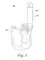
- FIG. 3is a perspective view illustrating another example embodiment of an implant assembly
- FIG. 4is a side view illustrating another embodiment of an attachment element of an implant assembly and an end of instrument configured to engage the attachment element;
- FIG. 5is a side view illustrating another embodiment of an attachment element of an implant assembly and an end of instrument configured to engage the attachment element;
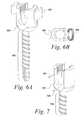
- FIG. 6Ais a perspective view illustrating another embodiment of an attachment element of an implant assembly
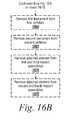
- FIG. 6Bis a top view of the instrument of FIG. 6A , illustrating the distal end of an instrument configured to engage the attachment element;
- FIG. 7is a perspective view illustrating another embodiment of an attachment element of an implant assembly
- FIG. 8is a perspective view illustrating one embodiment of an instrument used to manipulate a vertebral body
- FIG. 9is a perspective view illustrating another embodiment of an instrument used to manipulate a vertebral body
- FIG. 10is a close-up perspective view illustrating the attachment of the instrument of FIG. 9 to an implant assembly
- FIG. 11is a perspective view illustrating another embodiment of an instrument used to manipulate a vertebral body
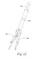
- FIG. 12is a perspective view illustrating another embodiment of an instrument used to manipulate a vertebral body
- FIG. 13is a perspective view illustrating another embodiment of an instrument used to manipulate a vertebral body
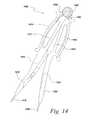
- FIG. 14is a perspective view illustrating another embodiment of an instrument used to manipulate a vertebral body
- FIG. 15is flow chart illustrating one embodiment of manipulating a vertebra using the implant assemblies and instruments disclosed herein;
- FIGS. 16A and 16Bare a flow chart illustrating one embodiment of manipulating a vertebra using the implant assemblies and multiple instruments disclosed herein;
- FIG. 17if side view illustrating the manipulation of vertebra as set forth in the method of FIGS. 16A and 16B ;
- FIG. 18is perspective view illustrating one embodiment of the connection of multiple instruments to a connector.
- FIG. 19is a perspective view of an assembly wherein the connector is attached to an operating table.
- the disclosed embodimentsprovide a system including an implant assembly and an instrument configured to work in conjunction to manipulate vertebral bodies to affect derotation.
- the implant assembliesinclude an attachment element that allows for the attachment of the instrument.
- the instrumentis configured to attach to two implant assemblies that have been inserted bilaterally into a vertebral body. When the instrument is attached to the implant assemblies, forces applied to the instrument are translated and transferred to the implant assemblies and the vertebral body into which the implant assemblies have been inserted thereby providing a rotational force on the vertebral body.
- an elementmeans one element or more than one element.
- FIG. 1depicts one embodiment of an implant assembly 100 .
- FIG. 1Adepicts an assembled view implant assembly 100 .
- the implant assembly 100includes a bone anchor 110 , a body 120 , and an removable attachment element 130 .
- the bone anchor 110has a proximal head not shown and a distal shaft 114 extending along a longitudinal axis configured to engage bone.
- the body 120is configured to engage the proximal head of bone anchor 110 and receive a spinal fixation element (not shown).
- the removable attachment element 130extends from the body 120 and is configured for connecting the implant assembly 100 to an instrument used to manipulate the implant assembly 100 .
- Each of these elementswill be described in more detail below.
- the distal shaft 114extends from the body 120 along a longitudinal axis 105 .
- the distal shaft 114is configured to engage bone.
- the distal shaft 114may be provided with threads 116 or other engagement configuration.
- the implant assembly 100is configured as an open head screw type.
- the body 120includes a U-shaped slot 122 for receiving a spinal fixation element, such as a rod (not shown).
- the body 120further includes a passage 124 for receiving the bone anchor 110 and engaging the proximal head of the bone anchor 110 .
- the distal shaft 114 of the bone anchor 110is passed through the passage 124 until the proximal head is engaged.
- the implant assembly 100 in this embodimentis a uniplanar or monoplanar screw; thus the body further includes a rod seat 226 that restrict the movement of the body 220 around the proximal head to one axis.
- a monoaxial screwin which the body does not rotate at all in relation to the bone anchor may be used.
- the removable attachment element 130 in this embodimentis a detachable tab extending from the body 120 .
- the tabs 130effectively extend the U-shaped slot 122 of the body 120 .
- the tab 130further defines a thru-hole 132 .
- the thru-holeprovides a convenient attachment point for connecting an instrument to the implant assembly 100 .
- the thru-hole 132creates a pin joint. Pinjoints do not transfer moments (or rotational forces) and as such a derotation force applied to the tab 230 result in push or pull forces rather than bending of the tab 130 when derotation is performed using the described instruments and techniques disclosed herein
- the removable tabs 130may be selectively detachable. This allows the tabs 130 to be removed after they have been used for de-rotation. By making the attachment elements 130 tabs extending from the body 120 , the overall profile of the implant assembly 100 is maintained. Once the tabs 130 are detached, the implant assembly 100 resembles a traditional implant assembly 100 allowing the use of existing instruments with the implant assembly 100 .
- the tabs 130may also include internal threads 134 allowing the tabs 130 to provide a certain degree or reduction of a spinal fixation element received in the U-shaped slot 122 of the body 120 .
- FIG. 2depicts another embodiment with an alternate tab 240 configuration.
- the screw assembly 200is largely the same as in FIG. 1 .
- the implant assembly 200includes a bone anchor 210 having a distal shaft 214 and a proximal head (not shown) connecting the bone anchor 210 to the body 220 .
- the body 220includes a U-shaped slot 222 for receiving a spinal fixation element, such as a rod (not shown).
- the body 220further includes a passage 224 for receiving the bone anchor 210 and engaging the proximal head of the bone anchor 210 .
- the implant assembly 200 in this embodimentis also a uniplanar or monoplanar screw.
- the bodyfurther includes a rod seat 226 that restrict the movement of the body 220 around the proximal head to one axis.
- the removable attachment elements 240are tabs extending from the body 220 of the implant assembly 200 .
- the tabs 240include a spherical undercut feature instead of a thru-hole.
- the arms 250 of the instrumentin turn are provided with a spherical connection element 252 that engage the spherical undercut feature.
- the spherical shape of the undercut feature and the connection elementprovide many of the same benefits as the pin joint in the embodiment of FIG. 2A .
- FIG. 3depicts another alternate configuration for a connection element 330 .
- the connection elementis a post 330 extending from the body 320 of the implant assembly 300 having a cylindrical shape.
- the instrument(not shown) passes over the post to engage the implant assembly 300 .
- the post 330may be provided with surface features 332 such as threads, or grooves to keep the instrument engaged with the implant assembly during derotation.
- the post 330is selectively detachable from connector body 320 . Once the post 330 is detached, the implant assembly 300 resembles a traditional implant assembly 300 allowing the use of existing instruments with the implant assembly 300 .
- FIGS. 4-7depict various embodiments wherein the attachment element may take on a number of geometries and configurations.
- the implant assembly 400includes bone anchor 410 , a body 420 , and removable attachment elements 430 .
- the bone anchor 410 and body 420are similar to those previously discussed.
- the body 420further includes engagement feature 424 that works in conjunction with the removable attachment elements.
- the attachment elements 430 in this exampleinclude tabs extending from the body including attachment features 432 .
- the engagement features 424 , 432are notches that angled away from each other.
- the notches 424 on the body 420are angled away from the notches 432 of the tabs 430 with are in turn angled away from the notches 424 of the body 420 .
- the end(s) of an instrument 470may be configured to engage the notches 424 and 432 .
- the end(s) of the instrument 470includes a first portion 472 and second portion 474 configured to engage the notches 424 and 432 .
- the attachment of the end of the instrument 470is achieved through distraction.
- the first portion 472 and second portion 474are slid relative to each other in the direction indicated by arrow 480 to secure the attachment.
- the tabs 430may be detached from the body 420 .
- the implant assembly 500includes bone anchor 510 , a body 520 , and removable attachment elements 530 .
- the bone anchor 510 and body 520are similar to those previously discussed.
- the bodyfurther includes engagement feature 524 .
- the removable attachment elements 530 in this exampleare tabs extending from the body 520 having further engagement features 532 .
- the engagement features 524 , 532are notches that angled toward each other.
- the notches 524 on the body 520are angled toward the notches 532 of the tabs 530 with are in turn angled toward the notches 524 of the body 520 .
- the end(s) of an instrument 570may be configured to engage the surface configurations 532 on the tabs 530 in combination with an annular ring 524 on the body 520 .
- the end(s) of the instrument 570includes a first portion 572 and second portion 574 configured to engage the surface configurations 532 and the annular ring 524 .
- the attachment of the end of the instrument 570is achieved through compression.
- the first portion 572 and second portion 574are slid relative to each other in the direction indicated by arrows 580 to secure the attachment.
- the tabs 530may be detached from the body 520 .
- FIG. 6A and 6Bdepict another embodiment of an implant assembly 600 .
- FIG. 6Ais a perspective view of the implant assembly 600 .
- FIG. 6Bis a top view of the implant assembly 600 showing the end of an instrument 670 configured to attach to the implant assembly 600 .
- the implant assembly 600includes bone anchor 610 , a body 620 , and removable attachment elements 630 .
- the bone anchor 610 and body 720are similar to those previously discussed.
- the removable attachment elements 630 in this exampleare tab extending from the body 620 .
- the end(s) of an instrument 670may be configured to engage the tabs 630 .
- the instrument 670could be provided with a clearance fit between the tabs 630 and the body 620 .
- the spacing between the tabs 630 and the body 620could taper providing a wedging effect when the instrument 670 is attached.
- the instrument 670could be tapered to create the wedging effect.
- the implant assembly 700includes bone anchor 710 , a body 720 , and removable attachment elements 730 .
- the bone anchor 710 and body 720are similar to those previously discussed.
- the attachment elements 830 in this examplecomprise one or more pins extending from the body 720 .
- the pinsmay operate similar to thru holes but instead of the instrument having pins to engage the thru holes on the body, the instrument has thru holes for engaging pins on the body. Once derotation has occurred, the pins 730 may be removed from the body 720 .
- the components of the implant assembly of the illustrative embodiments of the inventionmay be manufactured from any suitable biocompatible material, including, but not limited to, metals and metal alloys such as titanium and stainless steel, polymers and/or ceramics.
- the componentsmay be manufactured from the same or different materials though manufacturing processes known in the art.
- FIG. 8depicts one embodiment of an instrument 800 used for manipulating vertebra.
- the instrument 800includes a first arm 810 and a second arm 8920 pivotly connected to the first arm 810 .
- the first armhas a proximal end 812 and a distal end 814 .
- the distal end 814is configured to engage a first implant assembly as discussed above.
- the second arm 820also has a proximal end 822 and a distal end 824 .
- the distal end 822 of the second arm 820is configured to engage a second bone screw as discussed above.
- the instrumentmay further include a handle 830 disposed at the proximal end of at least one of the first or second arms.
- the handle 830is attached to the proximal end 812 of the first arm 810 .
- the handleprovides a user a convenient area to grip the instrument 800 and apply force for manipulating a vertebra.
- the second arm 820is attached to the first arm at a pivot 840 .
- the proximal end 822 of the second arm 820is further pivotably connected to a support arm 842 , which is pivotably connected to a push button or ratchet mechanism 844 on the first arm 810 .
- the push button or ratchet mechanism 844is moved along the length of the first arm 810 , the connected support arm 842 transfers the motion to the proximal end 822 of the second arm.
- Thiscauses the second arm 820 to rotate around pivot 840 .
- the distal ends 814 , 824 of the first and second arms 810 , 820are configured to engage implant assemblies as previously discussed, the distal ends 914 , 924 may be provided with specifically configured feet 816 , 826 for engaging the attachment element of the implant assembly.
- the feet 816 , 826are pins for engaging thru holes provided on an implant assembly.
- Other examples of feet and distal ends of instrumenthave been shown in FIGS. 2 and 4 - 6 . Still other embodiments and configurations will be apparent to one skilled in the art given the benefit of this disclosure.
- FIG. 9depicts another embodiment of an instrument 900 .
- the distal ends 912 and 922 of the first arm 910 and second arm 920are connected to a central shaft 940 as well as an adjustment mechanism 942 that rides along the central shaft 940 .
- Both the first arm 910 and second arm 920also include pivots 944 .
- the handle 930is connected to the adjustment mechanism 942 .
- the handleincludes a central bore 932 that allows the handle 930 to receive the central shaft 940 .
- the handle 930also is used to control the spacing of the first and second arm 910 , 920 .
- the adjustment mechanism 942is moved along the central shaft 940 . This movement is translated through pivots 944 and the pivotable connection to the central shaft 940 into movement of the distal ends 914 , 916 in the direction indicated by arrows 950 .
- the instrumenthas been attached to a first implant assembly 100 a and a second implant assembly 100 b inserted bilaterally in a vertebra 960 .
- the first implant assembly 100 ais attached to the first arm 910 and the second implant assembly 100 b is attached to the second arm 920 .
- the feet 916 , 926are configured to engage the respective attachment element of the respective implant assembly 100 a , 100 b .
- a close-up of the interconnection between a foot of the instrument and the attachment element of the implant assemblycan be seen in FIG. 10 .
- the foot 916 of the first arm 910 of the instrument 900is configured as a pin to engage a thru hole 132 in the removable attachment element 130 extending from the body 120 of the first implant assembly 100 a .
- Dashed line 1000indicated a possible trajectory for the insertion of the pin into the thru-hole 132 .
- the thru-hole 132provides a convenient attachment point for connecting an instrument to the implant assembly 100 .
- the thru-hole 132creates a pin joint. Pin joints do not transfer moments and as such, a rotational force applied to the instrument results in push or pull forces rather than bending of the tab 130 .
- the implant assemblies 100 a and 100 bmay be at different relative heights, angles, and rotations. Pin joints accommodate these variations better than many other geometries.
- FIGS. 11-14depict a number of embodiments of instruments with different positioning mechanisms.
- the instrumentis a modified parallel distractor used with the Expedium® screw system made by Depuy Spine.
- the spacing of the arms 1110 , 1120is actuated by squeezing the proximal handle 1130 .
- the distal ends 1114 , 1124have been modified to engage attachment elements 130 on the bilaterally implanted first and second implant assemblies 100 a , 100 b.
- the spacing of the first arm 1210 and second arm 1220is controlled be a mechanism 1232 in the handle 1230 .
- the mechanism 1232is a plunger mechanism. By actuating the plunger 1232 in the handle 1230 , the spacing of the first and second arms 1210 , 1220 is actuated.
- the second arm 1320is connected to the first arm 1310 at apivot 1340 .
- the handle 1330is attached to the proximal end of the second arm 1320 .
- a turnbuckle 1350is provided on the second arm 1320 to affect derotation.
- the first arm 1310is connected to a first implant in a first pedicle of a vertebra and the second arm 1320 is connected to a second implant in the second pedicle of the vertebra.
- the turnbuckle 1350is rotated, the length of the second arm is adjusted. Since the first arm 1310 and second arm 1320 are pivotly attached to each other, the adjustment of the length of the second arm 1320 causes the vertebra to rotate, thus derotating the vertebra.
- the first arm 1410 and the second arm 1420are connected at their respective proximal ends 1412 , 1422 by a pivot 1440 providing a caliper type configuration.
- the proximal ends 1412 , 1422also form the handle 1430 in this configuration.
- the distal ends 1414 , 1424are provided with feet 1416 , 1426 having pins configured to engage thru holes of an attachment element of the implant assembly described above.
- the instrument 1400further includes one or more connection elements 1450 for connecting instrument to a connector, such as an alignment rod (not shown).
- the components of the instrument of the illustrative embodimentsmay be manufactured from any suitable material, including, but not limited to, metals and metal alloys such as titanium and stainless steel, polymers and/or ceramics.
- the componentsmay be manufactured from the same or different materials though manufacturing processes known in the art.
- FIG. 15depicts an example flowchart 1500 of one embodiment of a method used for manipulating a vertebral body.
- the methodincludes inserting a first implant bilaterally into a vertebra (step 1510 ).
- a second implant assemblymay then be inserted into the vertebra bilaterally from the first implant assembly (step 1520 ).
- An instrumentmay then be attached to the first and second implant assemblies (step 1530 ). Once the instrument has been attached, the vertebra may then be manipulated using the instrument (step 1540 ).
- the methodmay further include the steps of attaching a first spinal fixation element to the first implant assembly (step 1550 ) and attaching a second spinal fixation element to the second implant assembly (step 1560 ).
- the instrumentmay be removed from the first implant assembly (step 1570 ) and the second implant assembly (step 1575 ). After the instrument has been removed, the removable attachment element of the first and second implant assemblies may be removed (steps 1580 and 1590 ).
- FIG. 16depicts an example flowchart 1600 of one embodiment of a method used for manipulating multiple vertebral bodies.
- the methodincludes inserting a first implant bilaterally into a first vertebra (step 1605 ).
- a second implant assemblymay then be inserted into the first vertebra bilaterally from the first implant assembly (step 1610 ).
- a third implant assemblymay be inserted bilaterally into a second vertebra (step 1615 ).
- a fourth implant assemblymay then be inserted bilaterally from the third implant assembly (step 1620 ).
- a first instrumentmay then be attached to the first and second implant assemblies (step 1625 ).
- a second instrumentmay also be attached to the third and fourth implant assemblies (step 1630 ). Once the first instrument has been attached, the first vertebra may then be manipulated using the first instrument (step 1635 ).
- the second vertebramay also be manipulated using the second instrument (step 1640 ).
- the methodmay also include connecting the first instrument to the second instrument using a connector (step 1645 ).
- the methodmay also include the steps of attaching a first spinal fixation element to the first and third implant assemblies (step 1650 ) and attaching a second spinal fixation element to the second and fourth implant assemblies (step 1655 ).
- the instrumentmay be removed from the first and second implant assembly of the first vertebra (step 1560 ) and the second instrument may be removed from the third and fourth implant assembly of the second vertebra (step 1565 ).
- the attachment element of the first and third implant assemblies inmay be removed (steps 1570 ) as well as the attachment elements of the second and fourth implant assemblies ( 1675 ).
- FIG. 17depict the manipulation of a two vertebrae using two instruments and implant assemblies described previously.
- the instruments 1400 a , 1400 bare the caliper type as describe in relation to FIG. 14 .
- the implant assemblies 100 a , 100 b , 100 c , 100 dare of the type described in relation to FIG. 1 . However, it should be understood that any of the embodiments of the implant assemblies or instrument may be used.
- first and second implant assemblies 100 a , 100 bhave been inserted bilaterally into the first vertebra 1750 .
- the third and fourth implant assemblies 100 c , 100 dhave been inserted bilaterally into the second vertebra 1760 .
- the distal end 1414 a of first arm 1410 a of the first instrument 1400 ais attached to the attachment element 130 a of the first implant assembly 100 a .
- the distal end of the second arm 1420 a of the first instrument 1400 ais attached to the attachment element 130 b of the second implant assembly 100 b .
- the distal end of first arm 1410 b of the second instrument 1400 bis attached to the attachment element 130 c of the third implant assembly 100 c .
- the distal end of the second arm 1420 b of the second instrument 1400 bis attached to the attachment element 130 d of the fourth implant assembly 100 d.
- the first and second vertebra 1750 , 1760may be manipulated individually or together in relation to each other or to other vertebrae.
- the first instrument 1400 ahas been used to orientate the first vertebra 1750 in relation to the second vertebra 1760 and both the first and second instruments 1400 a , 1400 b are used together to orientate the first and second vertebra 1750 , 1760 in relation to the other vertebra.
- instrumentsmay be provided with a connection element allowing the instrument to connect to a connector. Multiple instruments may thus be connected to the same connector (step 1645 of FIG. 16 ). An example of this can be seen in FIG. 18 .
- FIG. 18depicts a perspective view of multiple instruments connected to the same connector 1840 , such as an alignment rod.
- a first instrument 1810is attached to a first vertebra 1850 for manipulating the first vertebra 1850 .
- a second instrument 1820is attached to a second vertebra 1860 for manipulating the second vertebra 1860 .
- a third instrument 1830is attached to a third vertebra 1870 for manipulating the third vertebra 1870 .
- the first instrument 1810is provided with a connector element 1815 for connecting the first instrument 1810 to the alignment rod 1840 .
- the second instrument 2220is provided with a connector element 2225 for connecting the second instrument 1820 to the alignment rod 1840 .
- the third instrument 1830is provided with a connector element 1835 for connecting the third instrument 1830 to the alignment rod 1840 .
- each of the instruments 1810 , 1820 , 1830By connecting each of the instruments 1810 , 1820 , 1830 to the alignment rod 1840 , the orientation of each of the vertebra 1850 , 1860 , 1870 in relation to each other can be maintained while further manipulation or attachment of a spinal fixation element is performed.
- multiple connectors 1840may be used.
- the connector 1840may be connected to operating table to provide a fixed location for the connecter 1840 . An example of this can be seen in FIG. 19 .
- FIG. 19depict and example of an operation table 1900 .
- the table 1900is provided with one or more adjustable arms 1910 to which the connector 1840 is attached.
- the arms 1910are adjusted to place the connector in the desired orientation in relation to the patient's spine.
- Instruments 1600 a , 1600 bmay then be attached to the connector to maintain the vertebral bodies, to which the instruments 1600 a , 1600 b are attached, in proper alignment.
- the position of the connector 1840may be further adjusted at needed to maintain proper alignment.
- Other possible connections and configurationswill be apparent to one skilled in the art given the benefit of this disclosure.
Landscapes
- Health & Medical Sciences (AREA)
- Orthopedic Medicine & Surgery (AREA)
- Neurology (AREA)
- Life Sciences & Earth Sciences (AREA)
- Surgery (AREA)
- Heart & Thoracic Surgery (AREA)
- Engineering & Computer Science (AREA)
- Biomedical Technology (AREA)
- Nuclear Medicine, Radiotherapy & Molecular Imaging (AREA)
- Medical Informatics (AREA)
- Molecular Biology (AREA)
- Animal Behavior & Ethology (AREA)
- General Health & Medical Sciences (AREA)
- Public Health (AREA)
- Veterinary Medicine (AREA)
- Surgical Instruments (AREA)
- Prostheses (AREA)
Abstract
Description
Claims (7)
Priority Applications (1)
| Application Number | Priority Date | Filing Date | Title |
|---|---|---|---|
| US12/075,438US8709015B2 (en) | 2008-03-10 | 2008-03-10 | Bilateral vertebral body derotation system |
Applications Claiming Priority (1)
| Application Number | Priority Date | Filing Date | Title |
|---|---|---|---|
| US12/075,438US8709015B2 (en) | 2008-03-10 | 2008-03-10 | Bilateral vertebral body derotation system |
Publications (2)
| Publication Number | Publication Date |
|---|---|
| US20090228051A1 US20090228051A1 (en) | 2009-09-10 |
| US8709015B2true US8709015B2 (en) | 2014-04-29 |
Family
ID=41054452
Family Applications (1)
| Application Number | Title | Priority Date | Filing Date |
|---|---|---|---|
| US12/075,438Active2031-01-04US8709015B2 (en) | 2008-03-10 | 2008-03-10 | Bilateral vertebral body derotation system |
Country Status (1)
| Country | Link |
|---|---|
| US (1) | US8709015B2 (en) |
Cited By (6)
| Publication number | Priority date | Publication date | Assignee | Title |
|---|---|---|---|---|
| US20180125559A1 (en)* | 2016-11-04 | 2018-05-10 | Orthopedic Renovation Technologies, Llc | Pedicle screw removal tool and method of use |
| US20190105080A1 (en)* | 2017-10-06 | 2019-04-11 | Warsaw Orthopedic, Inc | Spinal implant system and methods of use |
| US10531904B2 (en) | 2014-04-30 | 2020-01-14 | Eric D. Kolb | Bone screw with apertures |
| US10702317B2 (en) | 2015-08-13 | 2020-07-07 | K2M, Inc. | Extended tab systems for reducing spinal rods |
| US11058461B2 (en)* | 2008-02-02 | 2021-07-13 | Globus Medical, Inc. | Intervertebral fusion implant |
| US11534223B2 (en)* | 2016-11-04 | 2022-12-27 | Orthopedic Renovation Technologies, Llc | Pedicle screw removal tool and method of use |
Families Citing this family (27)
| Publication number | Priority date | Publication date | Assignee | Title |
|---|---|---|---|---|
| US7887539B2 (en) | 2003-01-24 | 2011-02-15 | Depuy Spine, Inc. | Spinal rod approximators |
| US7951172B2 (en) | 2005-03-04 | 2011-05-31 | Depuy Spine Sarl | Constrained motion bone screw assembly |
| US7951175B2 (en) | 2005-03-04 | 2011-05-31 | Depuy Spine, Inc. | Instruments and methods for manipulating a vertebra |
| US8007522B2 (en) | 2008-02-04 | 2011-08-30 | Depuy Spine, Inc. | Methods for correction of spinal deformities |
| US8709015B2 (en) | 2008-03-10 | 2014-04-29 | DePuy Synthes Products, LLC | Bilateral vertebral body derotation system |
| US8608746B2 (en) | 2008-03-10 | 2013-12-17 | DePuy Synthes Products, LLC | Derotation instrument with reduction functionality |
| EP2265202B1 (en)* | 2008-04-22 | 2012-08-29 | Synthes GmbH | Bone fixation element with reduction tabs |
| US9504494B2 (en)* | 2008-04-28 | 2016-11-29 | DePuy Synthes Products, Inc. | Implants for securing spinal fixation elements |
| US10973556B2 (en) | 2008-06-17 | 2021-04-13 | DePuy Synthes Products, Inc. | Adjustable implant assembly |
| WO2011127065A1 (en) | 2010-04-06 | 2011-10-13 | Seaspine, Inc. | System and methods for correcting spinal deformities |
| US9060818B2 (en) | 2011-09-01 | 2015-06-23 | DePuy Synthes Products, Inc. | Bone implants |
| US10098665B2 (en) | 2012-08-01 | 2018-10-16 | DePuy Synthes Products, Inc. | Spine derotation system |
| US9402673B2 (en)* | 2012-09-28 | 2016-08-02 | DePuy Synthes Products, Inc. | Devices and methods for breaking and retaining surgical reduction tabs |
| US9782204B2 (en) | 2012-09-28 | 2017-10-10 | Medos International Sarl | Bone anchor assemblies |
| US9763702B2 (en) | 2012-11-16 | 2017-09-19 | DePuy Synthes Products, Inc. | Bone fixation assembly |
| US8951258B2 (en) | 2013-03-01 | 2015-02-10 | Warsaw Orthopedic, Inc. | Spinal correction system and method |
| US9259247B2 (en) | 2013-03-14 | 2016-02-16 | Medos International Sarl | Locking compression members for use with bone anchor assemblies and methods |
| US9724145B2 (en) | 2013-03-14 | 2017-08-08 | Medos International Sarl | Bone anchor assemblies with multiple component bottom loading bone anchors |
| US20140277153A1 (en) | 2013-03-14 | 2014-09-18 | DePuy Synthes Products, LLC | Bone Anchor Assemblies and Methods With Improved Locking |
| US9775660B2 (en) | 2013-03-14 | 2017-10-03 | DePuy Synthes Products, Inc. | Bottom-loading bone anchor assemblies and methods |
| US10342582B2 (en) | 2013-03-14 | 2019-07-09 | DePuy Synthes Products, Inc. | Bone anchor assemblies and methods with improved locking |
| US10028772B2 (en)* | 2014-10-07 | 2018-07-24 | Alphatec Spine, Inc. | Osteotomy instrument |
| US11109894B2 (en)* | 2016-09-26 | 2021-09-07 | Dr. Bryan Barnes Pc | Apparatus, system, and method for spinal vertebrae stabilization |
| US10736672B2 (en) | 2017-05-25 | 2020-08-11 | Warsaw Orthopedic, Inc. | Spinal implant system and method |
| US11382671B2 (en) | 2019-06-25 | 2022-07-12 | Warsaw Orthopedic, Inc. | Surgical instrument and method |
| US12023014B2 (en)* | 2020-04-10 | 2024-07-02 | Nextremity Solutions, Inc. | Ratcheting handle for medical instrument |
| WO2022184797A1 (en) | 2021-03-05 | 2022-09-09 | Medos International Sarl | Selectively locking polyaxial screw |
Citations (328)
| Publication number | Priority date | Publication date | Assignee | Title |
|---|---|---|---|---|
| US410780A (en) | 1889-09-10 | Maurice cah | ||
| US445513A (en) | 1891-01-27 | powell | ||
| US1470313A (en) | 1922-09-19 | 1923-10-09 | L M Tryer | Piston-ring squeezer |
| US1628144A (en) | 1924-05-16 | 1927-05-10 | Herrmann William | Screw driver |
| US1709766A (en) | 1926-09-16 | 1929-04-16 | Shawmut Eng Co | Yarn carrier |
| US1889330A (en) | 1932-02-23 | 1932-11-29 | Homer C Humes | Screw holding attachment for screw drivers |
| US1925385A (en) | 1932-11-08 | 1933-09-05 | Homer C Humes | Screw driver with screw holders |
| US2113246A (en) | 1937-05-17 | 1938-04-05 | Wappler Frederick Charles | Endoscopic forceps |
| US2248057A (en) | 1939-01-25 | 1941-07-08 | Bell Telephone Labor Inc | Electrical cutting device |
| US2248054A (en) | 1939-06-07 | 1941-07-08 | Becker Joseph | Screw driver |
| US2291413A (en) | 1941-06-13 | 1942-07-28 | John R Siebrandt | Bone clamping and wire adjusting means |
| US2370407A (en) | 1944-01-05 | 1945-02-27 | Zimmer Mfg Company | Screw driver |
| US2669896A (en) | 1951-01-19 | 1954-02-23 | Robert S Clough | Retractable jaw wrench having parallel resilient jaws |
| US2800820A (en) | 1954-06-04 | 1957-07-30 | Groov Pin Corp | Driver tool for self tapping inserts, struds, screw bolts, and the like |
| US2952285A (en) | 1958-12-09 | 1960-09-13 | Gramiger A G Geb | Screwdrivers |
| US3604487A (en) | 1969-03-10 | 1971-09-14 | Richard S Gilbert | Orthopedic screw driving means |
| US3960147A (en) | 1975-03-10 | 1976-06-01 | Murray William M | Compression bone staples and methods of compressing bone segments |
| US4237875A (en) | 1979-02-23 | 1980-12-09 | Towmotor Corporation | Dynamic intramedullary compression nailing |
| US4271836A (en) | 1976-06-28 | 1981-06-09 | Wyzsza Szkola Inzynierska Im. Jurija Gagarina | Appliance for correction of spinal curvatures |
| US4363250A (en) | 1980-04-04 | 1982-12-14 | Asakichi Suga | Device for driving screw, pin, rivet or the like |
| US4411259A (en) | 1980-02-04 | 1983-10-25 | Drummond Denis S | Apparatus for engaging a hook assembly to a spinal column |
| US4445513A (en) | 1981-05-29 | 1984-05-01 | Max Bernhard Ulrich | Device for straightening spinal column |
| US4655223A (en) | 1985-08-05 | 1987-04-07 | Kim Daniel S Y | Frenotomy method and apparatus |
| US4733657A (en) | 1984-04-16 | 1988-03-29 | Patrick Kluger | Apparatus for aligning a spinal column having damaged vertebrae |
| US4743260A (en) | 1985-06-10 | 1988-05-10 | Burton Charles V | Method for a flexible stabilization system for a vertebral column |
| US4809695A (en) | 1981-10-21 | 1989-03-07 | Owen M. Gwathmey | Suturing assembly and method |
| EP0328883A2 (en) | 1988-02-18 | 1989-08-23 | Howmedica GmbH | Supporting device for the human spinal column |
| US4887596A (en) | 1988-03-02 | 1989-12-19 | Synthes (U.S.A.) | Open backed pedicle screw |
| US4896661A (en) | 1988-02-05 | 1990-01-30 | Pfizer, Inc. | Multi purpose orthopedic ratcheting forceps |
| WO1990002527A1 (en) | 1988-09-09 | 1990-03-22 | Australian Defence Industries Pty. Limited | Spinal distractor |
| US4957495A (en) | 1987-04-01 | 1990-09-18 | Patrick Kluger | Device for setting the spinal column |
| US4987892A (en) | 1989-04-04 | 1991-01-29 | Krag Martin H | Spinal fixation device |
| DE3923996A1 (en) | 1989-07-20 | 1991-01-31 | Lutz Biedermann | RECORDING PART FOR JOINTLY CONNECTING TO A SCREW FOR MAKING A PEDICLE SCREW |
| US5005562A (en) | 1988-06-24 | 1991-04-09 | Societe De Fabrication De Material Orthopedique | Implant for spinal osteosynthesis device, in particular in traumatology |
| US5014407A (en) | 1989-09-28 | 1991-05-14 | Boughten Larry R | Tube expanding device |
| US5020519A (en) | 1990-12-07 | 1991-06-04 | Zimmer, Inc. | Sagittal approximator |
| US5067955A (en) | 1989-04-13 | 1991-11-26 | Societe De Fabrication De Material Orthopedique | Vertebral implant for osteosynthesis device |
| US5092866A (en) | 1989-02-03 | 1992-03-03 | Breard Francis H | Flexible inter-vertebral stabilizer as well as process and apparatus for determining or verifying its tension before installation on the spinal column |
| EP0487895A1 (en) | 1990-11-26 | 1992-06-03 | Synthes AG, Chur | Anchoring device |
| US5120171A (en) | 1990-11-27 | 1992-06-09 | Stuart Surgical | Bone screw with improved threads |
| DE4107480A1 (en) | 1991-03-08 | 1992-09-10 | Heinrich Ulrich | Screw for fixing appliance for correcting spinal column - has specially shaped head to receive appliance rod |
| FR2677242A1 (en) | 1991-06-05 | 1992-12-11 | Jeanson Jean Francois | Push-bar device for spinal support |
| US5176680A (en) | 1990-02-08 | 1993-01-05 | Vignaud Jean Louis | Device for the adjustable fixing of spinal osteosynthesis rods |
| US5176678A (en) | 1991-03-14 | 1993-01-05 | Tsou Paul M | Orthopaedic device with angularly adjustable anchor attachments to the vertebrae |
| US5181917A (en) | 1990-06-19 | 1993-01-26 | Chaim Rogozinski | System and method for instrumentation of the spine in the treatment of spinal deformities |
| US5181971A (en) | 1986-05-20 | 1993-01-26 | Canon Kabushiki Kaisha | Magnet and method of manufacturing the same |
| FR2680314A1 (en) | 1991-08-16 | 1993-02-19 | Lebosse Guy | Straight or curved coeliosurgery scissors with electrocoagulating fields in bipolar mode |
| US5219349A (en) | 1991-02-15 | 1993-06-15 | Howmedica, Inc. | Spinal fixator reduction frame |
| US5226766A (en) | 1990-11-27 | 1993-07-13 | Stuart Surgical | Bone screw with improved threads |
| US5263939A (en) | 1992-10-09 | 1993-11-23 | Surgin Surgical Instrumentation, Inc. | Retainer for laparoscopic cannula |
| US5282801A (en) | 1993-02-17 | 1994-02-01 | Danek Medical, Inc. | Top tightening clamp assembly for a spinal fixation system |
| EP0592266A1 (en) | 1992-10-07 | 1994-04-13 | Jean-Claude Bouvet | Rod locking device, especially for osteosynthesis or arthrodesis |
| USD346217S (en) | 1992-07-13 | 1994-04-19 | Acromed Corporation | Combined hook holder and rod mover for spinal surgery |
| US5306248A (en) | 1992-04-07 | 1994-04-26 | C. R. Bard, Inc. | Selectively controllable inflation-deflation device adapted for use in angioplasty procedures |
| DE4238339A1 (en) | 1992-11-13 | 1994-05-19 | Peter Brehm | Fastening screw for spinal column support rod - has hollow slotted head with female thread to accommodate grub-screw to firmly clamp rod in place |
| US5330474A (en) | 1991-09-23 | 1994-07-19 | Lin Chih I | Vertebral locking and retrieving system |
| US5360431A (en) | 1990-04-26 | 1994-11-01 | Cross Medical Products | Transpedicular screw system and method of use |
| US5364397A (en) | 1993-06-01 | 1994-11-15 | Zimmer, Inc. | Spinal coupler seater with dual jaws and an independent plunger |
| US5385565A (en) | 1992-09-21 | 1995-01-31 | Danek Medical, Inc. | Tool and method for derotating scoliotic spine |
| US5387213A (en) | 1991-02-05 | 1995-02-07 | Safir S.A.R.L. | Osseous surgical implant particularly for an intervertebral stabilizer |
| US5391170A (en) | 1991-12-13 | 1995-02-21 | David A. McGuire | Angled surgical screw driver and methods of arthroscopic ligament reconstruction |
| US5415661A (en) | 1993-03-24 | 1995-05-16 | University Of Miami | Implantable spinal assist device |
| US5429641A (en) | 1993-03-28 | 1995-07-04 | Gotfried; Yechiel | Surgical device for connection of fractured bones |
| US5468241A (en) | 1988-02-18 | 1995-11-21 | Howmedica Gmbh | Support device for the human vertebral column |
| US5478340A (en) | 1992-01-31 | 1995-12-26 | Kluger; Patrick | Vertebral column implant and repositioning instrument |
| US5484440A (en) | 1992-11-03 | 1996-01-16 | Zimmer, Inc. | Bone screw and screwdriver |
| US5487744A (en) | 1993-04-08 | 1996-01-30 | Advanced Spine Fixation Systems, Inc. | Closed connector for spinal fixation systems |
| EP0572790B1 (en) | 1992-06-04 | 1996-02-14 | Synthes AG, Chur | Osteosynthesis anchoring element |
| US5499983A (en) | 1994-02-23 | 1996-03-19 | Smith & Nephew Richards, Inc. | Variable angle spinal screw |
| US5501684A (en) | 1992-06-25 | 1996-03-26 | Synthes (U.S.A.) | Osteosynthetic fixation device |
| US5536127A (en) | 1994-10-13 | 1996-07-16 | Pennig; Dietmar | Headed screw construction for use in fixing the position of an intramedullary nail |
| US5536268A (en) | 1992-12-23 | 1996-07-16 | Plus Endoprothetik Ag | System for osteosynthesis at the vertebral column, connecting element for such a system and tool for its placement and removal |
| WO1996021396A1 (en) | 1995-01-12 | 1996-07-18 | Euros | Spinal fixator |
| US5540688A (en) | 1991-05-30 | 1996-07-30 | Societe "Psi" | Intervertebral stabilization device incorporating dampers |
| US5545165A (en) | 1992-10-09 | 1996-08-13 | Biedermann Motech Gmbh | Anchoring member |
| US5549608A (en) | 1995-07-13 | 1996-08-27 | Fastenetix, L.L.C. | Advanced polyaxial locking screw and coupling element device for use with rod fixation apparatus |
| US5551320A (en) | 1994-05-13 | 1996-09-03 | Horobec; Bill R. | System for the removing of threaded fasteners |
| US5591166A (en) | 1995-03-27 | 1997-01-07 | Smith & Nephew Richards, Inc. | Multi angle bone bolt |
| US5616143A (en) | 1995-02-06 | 1997-04-01 | Schlapfer; Johannes F. | Surgical forceps |
| EP0558883B1 (en) | 1992-03-02 | 1997-07-09 | Howmedica GmbH | Apparatus for bracing a plurality of vertebras of the human spine |
| US5649931A (en) | 1996-01-16 | 1997-07-22 | Zimmer, Inc. | Orthopaedic apparatus for driving and/or removing a bone screw |
| EP0784693A1 (en) | 1995-07-24 | 1997-07-23 | Transgene S.A. | Viral vectors and line for gene therapy |
| US5667513A (en) | 1995-06-07 | 1997-09-16 | Smith & Nephew Dyonics Inc. | Soft tissue anchor delivery apparatus |
| US5672175A (en) | 1993-08-27 | 1997-09-30 | Martin; Jean Raymond | Dynamic implanted spinal orthosis and operative procedure for fitting |
| US5672176A (en) | 1995-03-15 | 1997-09-30 | Biedermann; Lutz | Anchoring member |
| US5683399A (en) | 1995-12-01 | 1997-11-04 | Stelkast Incorporated | Acetabular cup insertion tool |
| US5697933A (en) | 1995-12-18 | 1997-12-16 | Medicinelodge, Inc. | Bone-tendon-bone drill guide |
| US5707371A (en) | 1992-02-28 | 1998-01-13 | Howmedica Gmbh | Repositioning tool |
| US5720751A (en) | 1996-11-27 | 1998-02-24 | Jackson; Roger P. | Tools for use in seating spinal rods in open ended implants |
| US5725532A (en) | 1996-09-10 | 1998-03-10 | Shoemaker; Steven | Integrated surgical reduction clamp and drill guide |
| US5746757A (en) | 1996-01-17 | 1998-05-05 | Mcguire; David A. | Suturing jig and method for using same |
| WO1998022033A1 (en) | 1996-11-15 | 1998-05-28 | Stryker France S.A. | Osteosynthesis system with elastic deformation for spinal column |
| WO1998025534A1 (en) | 1996-12-12 | 1998-06-18 | Synthes Ag Chur | Device for connecting a longitudinal support to a pedicle screw |
| DE29806563U1 (en) | 1998-04-09 | 1998-06-18 | Howmedica GmbH, 24232 Schönkirchen | Pedicle screw and assembly aid for it |
| US5782831A (en) | 1996-11-06 | 1998-07-21 | Sdgi Holdings, Inc. | Method an device for spinal deformity reduction using a cable and a cable tensioning system |
| US5797910A (en) | 1993-08-27 | 1998-08-25 | Paulette Fairant | Operative equipment for correcting a spinal deformity |
| US5797911A (en) | 1996-09-24 | 1998-08-25 | Sdgi Holdings, Inc. | Multi-axial bone screw assembly |
| US5810878A (en) | 1997-02-12 | 1998-09-22 | Sdgi Holdings, Inc. | Rod introducer forceps |
| US5814046A (en) | 1992-11-13 | 1998-09-29 | Sofamor S.N.C. | Pedicular screw and posterior spinal instrumentation |
| EP0885598A2 (en) | 1997-06-16 | 1998-12-23 | Howmedica GmbH | A receiving part for a retaining component of a vertebral column implant |
| US5879350A (en) | 1996-09-24 | 1999-03-09 | Sdgi Holdings, Inc. | Multi-axial bone screw assembly |
| US5882350A (en) | 1995-04-13 | 1999-03-16 | Fastenetix, Llc | Polyaxial pedicle screw having a threaded and tapered compression locking mechanism |
| US5885285A (en) | 1995-08-14 | 1999-03-23 | Simonson; Peter Melott | Spinal implant connection assembly |
| USRE36211E (en) | 1989-07-21 | 1999-05-18 | Brother Kogyo Kabushiki Kaisha | Communication managing data processing device in facsimile machine |
| EP0669109B1 (en) | 1994-02-28 | 1999-05-26 | Sulzer Orthopädie AG | Stabilizer for adjacent vertebrae |
| USRE36221E (en) | 1989-02-03 | 1999-06-01 | Breard; Francis Henri | Flexible inter-vertebral stabilizer as well as process and apparatus for determining or verifying its tension before installation on the spinal column |
| US5910141A (en) | 1997-02-12 | 1999-06-08 | Sdgi Holdings, Inc. | Rod introduction apparatus |
| US5941885A (en) | 1996-10-08 | 1999-08-24 | Jackson; Roger P. | Tools for use in installing osteosynthesis apparatus utilizing set screw with break-off head |
| WO1999044527A1 (en) | 1998-03-04 | 1999-09-10 | Dimso (Distribution Medicale Du Sud-Ouest) | Backbone osteosynthesis system with ligament |
| US5951579A (en) | 1997-10-06 | 1999-09-14 | Dykes; Ronald E. | Incision guide for intra-ocular surgery |
| US5951555A (en) | 1996-03-27 | 1999-09-14 | Rehak; Lubos | Device for the correction of spinal deformities |
| US5951564A (en) | 1996-12-18 | 1999-09-14 | Bristol-Myers Squibb Company | Orthopaedic positioning apparatus |
| US5964760A (en) | 1996-10-18 | 1999-10-12 | Spinal Innovations | Spinal implant fixation assembly |
| US5976133A (en) | 1997-04-23 | 1999-11-02 | Trustees Of Tufts College | External fixator clamp and system |
| US5989254A (en) | 1997-05-20 | 1999-11-23 | Katz; Akiva Raphael | Pedicle screw assembly |
| US5989250A (en) | 1996-10-24 | 1999-11-23 | Spinal Concepts, Inc. | Method and apparatus for spinal fixation |
| US6010509A (en) | 1998-07-01 | 2000-01-04 | The Dana Center For Orthopaedic Implants | Patella resection drill and prosthesis implantation device |
| US6050997A (en) | 1999-01-25 | 2000-04-18 | Mullane; Thomas S. | Spinal fixation system |
| US6090113A (en) | 1996-12-27 | 2000-07-18 | Stryker France S.A. | Adjustable osteosynthesis system of the rachis |
| EP1023873A2 (en) | 1999-01-30 | 2000-08-02 | Ja-Kyo Gu | Spinal fixation system |
| US6099528A (en) | 1997-05-29 | 2000-08-08 | Sofamor S.N.C. | Vertebral rod for spinal osteosynthesis instrumentation and osteosynthesis instrumentation, including said rod |
| US6123707A (en) | 1999-01-13 | 2000-09-26 | Spinal Concepts, Inc. | Reduction instrument |
| US6139549A (en) | 1996-04-09 | 2000-10-31 | Waldemar Link (Gmbh & Co.) | Spinal fixing device |
| US6146383A (en) | 1998-02-02 | 2000-11-14 | Sulzer Orthopadie Ag | Pivotal securing system at a bone screw |
| US6189422B1 (en) | 1998-07-17 | 2001-02-20 | Karl Storz Gmbh & Co. Kg | Screwdriver |
| US6210330B1 (en) | 1999-08-04 | 2001-04-03 | Rontech Medical Ltd. | Apparatus, system and method for real-time endovaginal sonography guidance of intra-uterine, cervical and tubal procedures |
| EP1090595A2 (en) | 1999-10-07 | 2001-04-11 | Stryker Spine SA | Slotted head pedicle screw assembly |
| US6235028B1 (en) | 2000-02-14 | 2001-05-22 | Sdgi Holdings, Inc. | Surgical guide rod |
| US6251112B1 (en) | 2000-04-18 | 2001-06-26 | Roger P. Jackson | Thin profile closure cap for open ended medical implant |
| WO2001045576A1 (en) | 1999-12-20 | 2001-06-28 | Synthes Ag Chur | Device for the stabilisation of two adjacent verterbral bodies of the spine |
| US6254602B1 (en) | 1999-05-28 | 2001-07-03 | Sdgi Holdings, Inc. | Advanced coupling device using shape-memory technology |
| US6258090B1 (en) | 2000-04-28 | 2001-07-10 | Roger P. Jackson | Closure for open ended medical implant and removal tool |
| DE10005386A1 (en) | 2000-02-07 | 2001-08-09 | Ulrich Gmbh & Co Kg | Pedicle screw for spinal implants takes round bar whose longitudinally rotating shoe notchably accepts notch-legged clip for bar. |
| DE10005385A1 (en) | 2000-02-07 | 2001-08-09 | Ulrich Gmbh & Co Kg | Pedicle screw |
| US6280442B1 (en) | 1999-09-01 | 2001-08-28 | Sdgi Holdings, Inc. | Multi-axial bone screw assembly |
| US6299616B1 (en) | 1998-11-07 | 2001-10-09 | Aesculap Ag & Co. Kg | Endoscopic insertion apparatus |
| US20010029376A1 (en) | 1998-05-12 | 2001-10-11 | Sater Ghaleb A. | Manual bone anchor placement devices |
| US6302888B1 (en) | 1999-03-19 | 2001-10-16 | Interpore Cross International | Locking dovetail and self-limiting set screw assembly for a spinal stabilization member |
| US6309389B1 (en) | 1997-02-26 | 2001-10-30 | Stryker France, S.A. | Ring for an angulation osteosynthesis device and osteosynthesis device incorporating same |
| WO2002007622A1 (en) | 2000-07-25 | 2002-01-31 | Spine Next | Flexible linking piece for stabilising the spine |
| US20020035366A1 (en) | 2000-09-18 | 2002-03-21 | Reto Walder | Pedicle screw for intervertebral support elements |
| US6368321B1 (en) | 2000-12-04 | 2002-04-09 | Roger P. Jackson | Lockable swivel head bone screw |
| US6371973B1 (en) | 1999-08-04 | 2002-04-16 | Ron-Tech Medical Ltd. | Forceps useful for intrabody guiding and/or positioning of a medical instrument |
| US6379357B1 (en) | 1994-10-25 | 2002-04-30 | Sdgi Holdings, Inc. | Modular spinal system |
| US20020082599A1 (en) | 2000-03-15 | 2002-06-27 | Dennis Crandall | Multidirectional pivoting bone screw and fixation system |
| US20020095153A1 (en) | 2001-09-12 | 2002-07-18 | Jones Robert J. | Spinal rod translation instrument |
| US6423065B2 (en) | 2000-02-25 | 2002-07-23 | Bret A. Ferree | Cross-coupled vertebral stabilizers including cam-operated cable connectors |
| US6440142B1 (en) | 2001-04-27 | 2002-08-27 | Third Millennium Engineering, Llc | Femoral ring loader |
| US6440133B1 (en) | 2001-07-03 | 2002-08-27 | Sdgi Holdings, Inc. | Rod reducer instruments and methods |
| US6440137B1 (en) | 2000-04-18 | 2002-08-27 | Andres A. Horvath | Medical fastener cap system |
| US6440144B1 (en) | 2000-04-19 | 2002-08-27 | Karl Storz Gmbh & Co. Kg | Medical instrument having a lockable force transmitting element |
| US6443953B1 (en) | 2000-02-08 | 2002-09-03 | Cross Medical Products, Inc. | Self-aligning cap nut for use with a spinal rod anchor |
| US20020133155A1 (en) | 2000-02-25 | 2002-09-19 | Ferree Bret A. | Cross-coupled vertebral stabilizers incorporating spinal motion restriction |
| US20020143341A1 (en) | 2001-03-27 | 2002-10-03 | Lutz Biedermann | Anchoring element |
| DE20207851U1 (en) | 2002-05-21 | 2002-10-10 | Metz-Stavenhagen, Peter, Dr.med., 34537 Bad Wildungen | Anchoring element for fastening a rod of a device for setting up a human or animal spine to a vertebral bone |
| US6478798B1 (en) | 2001-05-17 | 2002-11-12 | Robert S. Howland | Spinal fixation apparatus and methods for use |
| WO2002102259A2 (en) | 2001-06-16 | 2002-12-27 | Dilip Kumar Sengupta | An assembly for the stabilisation of vertebral bodies of the spine |
| US6511484B2 (en) | 2001-06-29 | 2003-01-28 | Depuy Acromed, Inc. | Tool and system for aligning and applying fastener to implanted anchor |
| WO2003007828A1 (en) | 2001-07-18 | 2003-01-30 | Frederic Fortin | Flexible vertebral linking device |
| US20030028195A1 (en) | 2001-07-25 | 2003-02-06 | Stephane Bette | Ancillary for spinal osteosynthesis system and process for implanting a spinal osteosynthesis system using the said ancillary |
| US6530929B1 (en) | 1999-10-20 | 2003-03-11 | Sdgi Holdings, Inc. | Instruments for stabilization of bony structures |
| EP1295566A1 (en) | 1999-06-30 | 2003-03-26 | Surgival Co., S.A. | Polyaxial vertebral fixing system |
| US6540748B2 (en) | 1999-09-27 | 2003-04-01 | Blackstone Medical, Inc. | Surgical screw system and method of use |
| US20030073995A1 (en) | 2001-10-15 | 2003-04-17 | Reed Gary Jack | Orthopedic stabilization device and method |
| WO2003032863A2 (en) | 2001-10-15 | 2003-04-24 | Reed Gary J | Orthopedic stabilization device and method |
| US20030083747A1 (en) | 2001-10-30 | 2003-05-01 | Osteotech, Inc. | Bone implant and isertion tools |
| US20030083657A1 (en) | 2001-10-30 | 2003-05-01 | Drewry Troy D. | Flexible spinal stabilization system and method |
| US20030088248A1 (en) | 2001-11-07 | 2003-05-08 | Reed Gary Jack | Orthopedic stabilization device and method |
| US6565567B1 (en) | 1996-12-20 | 2003-05-20 | Thomas T. Haider | Pedicle screw for osteosynthesis |
| US20030100896A1 (en) | 2001-11-27 | 2003-05-29 | Lutz Biedermann | Element with a shank and a holding element connected to it for connecting to a rod |
| US20030105460A1 (en) | 2000-03-15 | 2003-06-05 | Dennis Crandall | Multidirectional pivoting bone screw and fixation system |
| US20030109880A1 (en) | 2001-08-01 | 2003-06-12 | Showa Ika Kohgyo Co., Ltd. | Bone connector |
| US20030114852A1 (en) | 2001-01-12 | 2003-06-19 | Lutz Biedermann | Connector element for bone rods or spinal rods |
| WO2003049629A1 (en) | 2001-12-12 | 2003-06-19 | Ldr Medical | Implant for osseous anchoring with polyaxial head |
| US20030125750A1 (en) | 2001-11-05 | 2003-07-03 | Zwirnmann Ralph Fritz | Spring loaded fixation element insertion device |
| US6597279B1 (en) | 1998-03-06 | 2003-07-22 | Sony Corporation | Portable information terminal and method of setting the same |
| EP0880344B1 (en) | 1996-02-15 | 2003-08-06 | Prof. Dr. med. Peter Griss | Osteosynthetic mounting element |
| US20030149438A1 (en) | 2001-04-30 | 2003-08-07 | Howmedica Osteonics Corp. | Insertion instrument |
| US20030171749A1 (en) | 2000-07-25 | 2003-09-11 | Regis Le Couedic | Semirigid linking piece for stabilizing the spine |
| US20030176861A1 (en) | 2002-03-15 | 2003-09-18 | Reed Gary J. | Orthopedic stabilization device and method |
| US6623485B2 (en) | 2001-10-17 | 2003-09-23 | Hammill Manufacturing Company | Split ring bone screw for a spinal fixation system |
| US20030191470A1 (en) | 2002-04-05 | 2003-10-09 | Stephen Ritland | Dynamic fixation device and method of use |
| US20030191370A1 (en) | 2002-04-05 | 2003-10-09 | Phillips Burns P. | Side loading surgical retractor |
| US20030199872A1 (en) | 2002-04-17 | 2003-10-23 | Stryker Spine | Rod persuader |
| US6648888B1 (en) | 2002-09-06 | 2003-11-18 | Endius Incorporated | Surgical instrument for moving a vertebra |
| US6652523B1 (en) | 1998-12-29 | 2003-11-25 | Delegation General Pour L'armement | Monolateral orthopedic device with external fixing for immobilizing a fractured bone |
| US20030220642A1 (en) | 2002-05-21 | 2003-11-27 | Stefan Freudiger | Elastic stabilization system for vertebral columns |
| US20030220643A1 (en) | 2002-05-24 | 2003-11-27 | Ferree Bret A. | Devices to prevent spinal extension |
| US20030225408A1 (en) | 2002-06-04 | 2003-12-04 | Howmedica Osteonics Corp. | Apparatus for securing a spinal rod system |
| US20040002708A1 (en) | 2002-05-08 | 2004-01-01 | Stephen Ritland | Dynamic fixation device and method of use |
| US6689137B2 (en) | 2001-10-15 | 2004-02-10 | Gary Jack Reed | Orthopedic fastener and method |
| US6695843B2 (en) | 2000-12-22 | 2004-02-24 | Biedermann Motech Gmbh | Fixing element |
| US20040036254A1 (en) | 2002-08-21 | 2004-02-26 | Patton Prudence R. | System and method for costuming and decorating a wheelchair |
| US20040049190A1 (en) | 2002-08-09 | 2004-03-11 | Biedermann Motech Gmbh | Dynamic stabilization device for bones, in particular for vertebrae |
| WO2004019755A2 (en) | 2002-08-28 | 2004-03-11 | Ashman Richard B | Variable angle spinal implant connection assembly |
| US6716214B1 (en) | 2003-06-18 | 2004-04-06 | Roger P. Jackson | Polyaxial bone screw with spline capture connection |
| US20040073215A1 (en) | 2002-10-14 | 2004-04-15 | Scient ' X | Dynamic intervertebral connection device with controlled multidirectional deflection |
| US6733502B2 (en) | 2002-05-15 | 2004-05-11 | Cross Medical Products, Inc. | Variable locking spinal screw having a knurled collar |
| US20040102789A1 (en) | 2002-11-22 | 2004-05-27 | Scimed Life Systems, Inc. | Selectively locking device |
| US6743231B1 (en) | 2000-10-02 | 2004-06-01 | Sulzer Spine-Tech Inc. | Temporary spinal fixation apparatuses and methods |
| US6749613B1 (en) | 1999-02-18 | 2004-06-15 | Stryker Spine | Distraction/contraction device for spinal osteosynthesis system |
| US6752832B2 (en) | 2000-12-27 | 2004-06-22 | Ulrich Gmbh & Co., Kg | Vertebral implant and setting tool therefor |
| US6755829B1 (en) | 2000-09-22 | 2004-06-29 | Depuy Acromed, Inc. | Lock cap anchor assembly for orthopaedic fixation |
| US20040147936A1 (en) | 2003-01-28 | 2004-07-29 | Rosenberg William S. | Spinal rod approximator |
| US20040147937A1 (en) | 2003-01-24 | 2004-07-29 | Depuy Spine, Inc. | Spinal rod approximators |
| US20040158257A1 (en) | 2003-02-12 | 2004-08-12 | Bonati Alfred O. | Extractor tube for removing orthopaedic hardware |
| US20040158258A1 (en) | 2003-02-12 | 2004-08-12 | Bonati Alfred O. | Method for removing orthopaedic hardware |
| US20040172057A1 (en) | 2003-02-27 | 2004-09-02 | Guillebon Henri De | Super atraumatic grasper apparatus |
| US20040176779A1 (en) | 2003-02-03 | 2004-09-09 | Guido Casutt | Targeting aid |
| US6790208B2 (en) | 2000-03-28 | 2004-09-14 | Showa Ika Kohgyo Co., Ltd. | Rod gripper |
| US20040181224A1 (en) | 2003-03-11 | 2004-09-16 | Biedermann Motech Gmbh | Anchoring element for use in spine or bone surgery, methods for use and production thereof |
| US20040186473A1 (en) | 2003-03-21 | 2004-09-23 | Cournoyer John R. | Spinal fixation devices of improved strength and rigidity |
| US20040204711A1 (en) | 2003-04-09 | 2004-10-14 | Jackson Roger P. | Polyaxial bone screw locking mechanism |
| US20040220567A1 (en) | 2003-02-12 | 2004-11-04 | Sdgi Holdings, Inc. | Instruments and methods for aligning implants for insertion |
| US20040225289A1 (en) | 2003-05-07 | 2004-11-11 | Biedermann Motech Gmbh | Dynamic anchoring device and dynamic stabilization device for bones, in particular for vertebrae, with such an anchoring device |
| US20040243139A1 (en) | 2003-04-28 | 2004-12-02 | Lewis Derek S. | Multiple screw delivery apparatus |
| US6827722B1 (en) | 2001-12-11 | 2004-12-07 | Biomet, Inc. | Method and apparatus for use of a guide wire capturing surgical instrument |
| US20040254576A1 (en) | 2003-06-16 | 2004-12-16 | Depuy Acromed, Inc. | Rod reduction nut and driver tool |
| US20040267260A1 (en) | 2003-06-16 | 2004-12-30 | Thomas Mack | Implant for correction and stabilization of the spinal column |
| US20040267275A1 (en) | 2003-06-26 | 2004-12-30 | Cournoyer John R. | Spinal implant holder and rod reduction systems and methods |
| US6837889B2 (en) | 2002-03-01 | 2005-01-04 | Endius Incorporated | Apparatus for connecting a longitudinal member to a bone portion |
| US20050015095A1 (en) | 2003-07-15 | 2005-01-20 | Cervitech, Inc. | Insertion instrument for cervical prostheses |
| WO2005006948A2 (en) | 2003-07-03 | 2005-01-27 | Hfsc Company | Top loading spinal fixation device and instruments for loading and handling the same |
| US20050033291A1 (en) | 2003-05-22 | 2005-02-10 | Sohei Ebara | Surgical device for correction of spinal deformity and method for using same |
| US20050033295A1 (en) | 2003-08-08 | 2005-02-10 | Paul Wisnewski | Implants formed of shape memory polymeric material for spinal fixation |
| US20050055031A1 (en) | 2003-09-10 | 2005-03-10 | Roy Lim | Devices and methods for inserting spinal implants |
| US20050059969A1 (en) | 2003-09-17 | 2005-03-17 | Depuy Acromed, Inc. | Rod approximator |
| US20050065516A1 (en) | 2003-09-24 | 2005-03-24 | Tae-Ahn Jahng | Method and apparatus for flexible fixation of a spine |
| US20050065517A1 (en) | 2003-09-24 | 2005-03-24 | Chin Kingsley Richard | Methods and devices for improving percutaneous access in minimally invasive surgeries |
| US20050065514A1 (en) | 2001-12-07 | 2005-03-24 | Armin Studer | Damping element |
| US20050070917A1 (en) | 2003-09-29 | 2005-03-31 | Justis Jeff R. | Instruments and methods for securing a connecting element along a bony segment |
| WO2005030065A1 (en) | 2003-09-26 | 2005-04-07 | Synthes Gmbh | Device for connecting a longitudinal carrier to a bone |
| US20050079909A1 (en) | 2003-10-14 | 2005-04-14 | Lertyos Singhaseni | Method for player-influenced random distribution of game tokens |
| US20050085815A1 (en) | 2003-10-17 | 2005-04-21 | Biedermann Motech Gmbh | Rod-shaped implant element for application in spine surgery or trauma surgery, stabilization apparatus comprising said rod-shaped implant element, and production method for the rod-shaped implant element |
| US20050085813A1 (en) | 2003-10-21 | 2005-04-21 | Innovative Spinal Technologies | System and method for stabilizing of internal structures |
| US20050090824A1 (en) | 2003-10-22 | 2005-04-28 | Endius Incorporated | Method and surgical tool for inserting a longitudinal member |
| WO2005044117A2 (en) | 2003-11-07 | 2005-05-19 | Biedermann Motech Gmbh | Spring element for a bone stabilizing device, and method for the production of said spring element |
| WO2005044123A1 (en) | 2003-11-07 | 2005-05-19 | Biedermann Motech Gmbh | Bone fixing element and stabilising device comprising one such bone fixing element |
| US20050131420A1 (en) | 2003-12-16 | 2005-06-16 | Techiera Richard C. | Pivoting implant holder |
| US20050131421A1 (en) | 2003-12-16 | 2005-06-16 | Anderson David G. | Methods and devices for minimally invasive spinal fixation element placement |
| US20050131422A1 (en) | 2003-12-16 | 2005-06-16 | Anderson David G. | Methods and devices for spinal fixation element placement |
| US20050131408A1 (en)* | 2003-12-16 | 2005-06-16 | Sicvol Christopher W. | Percutaneous access devices and bone anchor assemblies |
| US20050143749A1 (en) | 2003-12-31 | 2005-06-30 | Depuy Spine, Inc. | Inserter instrument and implant clip |
| US20050149053A1 (en) | 2003-12-17 | 2005-07-07 | Varieur Michael S. | Instruments and methods for bone anchor engagement and spinal rod reduction |
| US20050149048A1 (en) | 2003-12-23 | 2005-07-07 | Eurosurgical Sa | Surgical instrument of the releaser type for a spinal implant |
| US20050159650A1 (en) | 2003-12-18 | 2005-07-21 | Depuy Spine, Inc. | Surgical methods and surgical kits |
| US20050177163A1 (en) | 2003-12-29 | 2005-08-11 | Abdou M. S. | Plating system for bone fixation and method of implantation |
| US20050192573A1 (en) | 2004-02-27 | 2005-09-01 | Custom Spine, Inc. | Biased angle polyaxial pedicle screw assembly |
| US20050192570A1 (en) | 2004-02-27 | 2005-09-01 | Jackson Roger P. | Orthopedic implant rod reduction tool set and method |
| US20050192589A1 (en) | 2004-02-06 | 2005-09-01 | Douglas Raymond | Devices and methods for inserting a spinal fixation element |
| US20050192579A1 (en) | 2004-02-27 | 2005-09-01 | Jackson Roger P. | Orthopedic implant rod reduction tool set and method |
| EP1574175A1 (en) | 2004-03-09 | 2005-09-14 | Showa IKA Kohgyo Co., Ltd. | Auxiliary instrument for fixing rod |
| US20050228376A1 (en) | 2004-03-31 | 2005-10-13 | Boomer Mark C | Adjustable-angle spinal fixation element |
| US20050228400A1 (en) | 2004-03-31 | 2005-10-13 | Chao Nam T | Instrument for inserting, adjusting and removing pedicle screws and other orthopedic implants |
| US20050228392A1 (en) | 2004-04-12 | 2005-10-13 | Keyer Thomas R | Rod persuader |
| US20050228380A1 (en) | 2004-04-09 | 2005-10-13 | Depuy Spine Inc. | Instruments and methods for minimally invasive spine surgery |
| US20050234449A1 (en) | 2002-07-10 | 2005-10-20 | Joseph Aferzon | Spinal support coupling device |
| US20050245928A1 (en) | 2004-05-03 | 2005-11-03 | Innovative Spinal Technologies | System and method for displacement of bony structures |
| US20050261687A1 (en) | 2004-04-20 | 2005-11-24 | Laszlo Garamszegi | Pedicle screw assembly |
| US20050283244A1 (en) | 2003-08-05 | 2005-12-22 | Gordon Charles R | Method of insertion of an expandable intervertebral implant |
| US20050288668A1 (en) | 2002-06-24 | 2005-12-29 | Bernhard Brinkhaus | Spinal column support system |
| US20060009775A1 (en) | 2004-07-06 | 2006-01-12 | Brian Dec | Spinal rod insertion instrument |
| US20060036254A1 (en) | 2004-08-10 | 2006-02-16 | Roy Lim | Reducing instrument for spinal surgery |
| US20060036255A1 (en) | 2004-08-13 | 2006-02-16 | Pond John D Jr | System and method for positioning a connecting member adjacent the spinal column in minimally invasive procedures |
| US20060036260A1 (en) | 2004-08-06 | 2006-02-16 | Runco Thomas J | Instrument for guiding a rod into an implant in a spinal fixation system |
| US20060069391A1 (en) | 2004-02-27 | 2006-03-30 | Jackson Roger P | Spinal fixation tool attachment structure |
| US20060074418A1 (en) | 2004-09-24 | 2006-04-06 | Jackson Roger P | Spinal fixation tool set and method for rod reduction and fastener insertion |
| US20060079909A1 (en) | 2003-12-17 | 2006-04-13 | Runco Thomas J | Instruments and methods for bone anchor engagement and spinal rod reduction |
| US20060089651A1 (en) | 2004-10-26 | 2006-04-27 | Trudeau Jeffrey L | Apparatus and method for anchoring a surgical rod |
| US20060095035A1 (en) | 2004-11-03 | 2006-05-04 | Jones Robert J | Instruments and methods for reduction of vertebral bodies |
| US20060111712A1 (en) | 2004-11-23 | 2006-05-25 | Jackson Roger P | Spinal fixation tool set and method |
| US20060111713A1 (en) | 2004-11-23 | 2006-05-25 | Jackson Roger P | Spinal fixation tool set and method |
| US20060111730A1 (en) | 2004-11-23 | 2006-05-25 | Medical Innovators, Inc. | Deformity reduction instrument and method |
| US20060149236A1 (en) | 2004-12-30 | 2006-07-06 | Barry Mark A | System and method for aligning vertebrae in the amelioration of aberrant spinal column deviation conditions |
| US20060166534A1 (en) | 2005-01-26 | 2006-07-27 | Brumfield David L | Reducing instrument for spinal surgery |
| US7083621B2 (en) | 2003-04-25 | 2006-08-01 | Sdgi Holdings, Inc. | Articulating spinal fixation rod and system |
| US20060173454A1 (en) | 2003-10-21 | 2006-08-03 | Innovative Spinal Technologies | Internal structure stabilization system for spanning three or more structures |
| US20060195092A1 (en) | 2004-12-30 | 2006-08-31 | Barry Mark A | System and method for aligning vertebrae in the amelioration of aberrant spinal column deviation conditions |
| US20060200132A1 (en) | 2005-03-04 | 2006-09-07 | Chao Nam T | Instruments and methods for manipulating a vertebra |
| US20060200131A1 (en) | 2005-03-04 | 2006-09-07 | Depuy Spine Sarl | Constrained motion bone screw assembly |
| US20060217735A1 (en) | 2005-03-11 | 2006-09-28 | Macdonald Joel | Bone repair device and method |
| US20060229605A1 (en) | 2005-03-18 | 2006-10-12 | Olsen Ron A | Adjustable splint for osteosynthesis with incrementing assembly for adjustment in predetermined increments |
| US20060247630A1 (en) | 2005-04-27 | 2006-11-02 | Andrew Iott | Percutaneous vertebral stabilization system |
| US20060264934A1 (en) | 2005-05-18 | 2006-11-23 | Medicinelodge, Inc. | System and method for orthopedic implant configuration |
| US20060271050A1 (en) | 2005-03-30 | 2006-11-30 | Gabriel Piza Vallespir | Instrumentation and methods for reducing spinal deformities |
| US20060282073A1 (en) | 2003-04-03 | 2006-12-14 | Naum Simanovsky | Implant for treating idiopathic scoliosis and a method for using the same |
| US20060293692A1 (en) | 2005-06-02 | 2006-12-28 | Whipple Dale E | Instruments and methods for manipulating a spinal fixation element |
| US20060293690A1 (en) | 2005-05-23 | 2006-12-28 | Custom Spine, Inc. | Rod reducer |
| US7179254B2 (en) | 2004-03-09 | 2007-02-20 | Ethicon, Inc. | High intensity ablation device |
| US20070078460A1 (en) | 2005-08-25 | 2007-04-05 | Robert Frigg | Methods of spinal fixation and instrumentation |
| US20070093849A1 (en) | 2005-09-29 | 2007-04-26 | Jones Scott A | Single action anti-torque rod reducer |
| US20070173831A1 (en) | 2005-11-14 | 2007-07-26 | Abdou M S | Device and method for the placement of spinal fixators |
| US7250052B2 (en) | 2002-10-30 | 2007-07-31 | Abbott Spine Inc. | Spinal stabilization systems and methods |
| US20070185375A1 (en) | 2006-02-06 | 2007-08-09 | Depuy Spine, Inc. | Medical device installation tool |
| US20070191836A1 (en) | 2006-01-27 | 2007-08-16 | Sdgi Holdings, Inc. | Methods and devices for a minimally invasive placement of a rod within a patient |
| WO2007092876A2 (en) | 2006-02-09 | 2007-08-16 | Warsaw Orthopedic, Inc. | Methods and instruments for spinal derotation |
| WO2007092797A2 (en) | 2006-02-09 | 2007-08-16 | Warsaw Orthopedic, Inc | Spinal derotation instruments and methods |
| WO2007092870A2 (en) | 2006-02-07 | 2007-08-16 | Warsaw Orthopedic, Inc. | Surgical instruments and techniques for percutaneous placement of spinal stabilization elements |
| JP2007525274A (en) | 2004-02-27 | 2007-09-06 | ロジャー・ピー・ジャクソン | Orthopedic implant rod reduction instrument set and method |
| US20070213722A1 (en) | 2006-03-09 | 2007-09-13 | Jones Scott A | Dual action rod reducing and locking device and method |
| US20070231059A1 (en) | 2006-02-22 | 2007-10-04 | Mullaney Michael W | Articulation apparatus for external fixation device |
| US20070233079A1 (en) | 2006-02-06 | 2007-10-04 | Stryker Spine | Rod contouring apparatus and method for percutaneous pedicle screw extension |
| US20070270880A1 (en) | 2006-04-28 | 2007-11-22 | Lindemann Gary S | Bone screw revision tools and methods of use |
| WO2007149426A2 (en) | 2006-06-16 | 2007-12-27 | Alphatec Spine, Inc. | Systems and methods for manipulating and/or installing a pedicle screw |
| US7320689B2 (en) | 2003-07-15 | 2008-01-22 | Cervitech, Inc. | Multi-part cervical endoprosthesis with insertion instrument |
| US20080045956A1 (en) | 2005-02-23 | 2008-02-21 | Pioneer Laboratories, Inc. | Minimally invasive surcigal system |
| WO2008024937A2 (en) | 2006-08-23 | 2008-02-28 | Pioneer Surgical Technology, Inc. | Minimally invasive surgical system |
| US20080077135A1 (en) | 2006-09-26 | 2008-03-27 | Depuy Spine, Inc. | Minimally invasive bone anchor extensions |
| US20080172062A1 (en) | 2007-01-12 | 2008-07-17 | Depuy Spine, Inc. | Bone anchor manipulation device |
| US20080195159A1 (en) | 2005-02-08 | 2008-08-14 | Henning Kloss | Spine Fixator |
| US20080243190A1 (en) | 2007-03-29 | 2008-10-02 | Depuy Spine, Inc. | In-line rod reduction device and methods |
| US20080255574A1 (en) | 2007-04-13 | 2008-10-16 | Zimmer Technology, Inc. | Instrument for insertion of prosthetic components |
| US20090018541A1 (en) | 2007-06-27 | 2009-01-15 | Abraham Lavi | Multi-angle clamp |
| US20090030419A1 (en) | 2007-07-26 | 2009-01-29 | Depuy Spine, Inc. | Spinal rod reduction instruments and methods for use |
| US7485120B2 (en) | 2003-12-31 | 2009-02-03 | Ray Charles D | Tapered bone fusion cages or blocks, implantation means and method |
| US7491208B2 (en) | 2005-04-28 | 2009-02-17 | Warsaw Orthopedic, Inc. | Instrument and method for guiding surgical implants and instruments during surgery |
| US20090054902A1 (en) | 2007-08-21 | 2009-02-26 | Depuy Spine, Inc. | Tether tensioning instrument |
| US20090062857A1 (en) | 2007-08-31 | 2009-03-05 | Ramsay Christopher L | Minimally invasive guide system |
| US20090082811A1 (en) | 2007-09-26 | 2009-03-26 | Depuy Spine, Inc. | Devices and methods for positioning a spinal fixation element |
| US20090088764A1 (en) | 2007-09-28 | 2009-04-02 | Depuy Spine, Inc. | Dual pivot instrument for reduction of a fixation element and method of use |
| US20090143828A1 (en) | 2007-10-04 | 2009-06-04 | Shawn Stad | Methods and Devices For Minimally Invasive Spinal Connection Element Delivery |
| US20090228053A1 (en) | 2008-03-10 | 2009-09-10 | Eric Kolb | Derotation instrument with reduction functionality |
| US20090228051A1 (en) | 2008-03-10 | 2009-09-10 | Eric Kolb | Bilateral vertebral body derotation system |
| US7588585B2 (en) | 2002-03-26 | 2009-09-15 | Novare Surgical Systems, Inc. | Handleless clamping device |
| US7591836B2 (en) | 2004-07-30 | 2009-09-22 | Zimmer Spine, Inc. | Surgical devices and methods for vertebral shifting utilizing spinal fixation systems |
| US7666189B2 (en) | 2004-09-29 | 2010-02-23 | Synthes Usa, Llc | Less invasive surgical system and methods |
| US7867237B2 (en) | 2005-10-31 | 2011-01-11 | Depuy Spine, Inc. | Arthroplasty revision device and method |
| US20110077689A1 (en) | 2009-09-23 | 2011-03-31 | Depuy Spine, Inc. | Methods and Devices for Manipulating a Vertebra |
Family Cites Families (1)
| Publication number | Priority date | Publication date | Assignee | Title |
|---|---|---|---|---|
| US20070032531A1 (en)* | 2005-08-04 | 2007-02-08 | Apogee Biotechnology Corporation | Sphingosine kinase inhibitors and methods of their use |
- 2008
- 2008-03-10USUS12/075,438patent/US8709015B2/enactiveActive
Patent Citations (422)
| Publication number | Priority date | Publication date | Assignee | Title |
|---|---|---|---|---|
| US410780A (en) | 1889-09-10 | Maurice cah | ||
| US445513A (en) | 1891-01-27 | powell | ||
| US1470313A (en) | 1922-09-19 | 1923-10-09 | L M Tryer | Piston-ring squeezer |
| US1628144A (en) | 1924-05-16 | 1927-05-10 | Herrmann William | Screw driver |
| US1709766A (en) | 1926-09-16 | 1929-04-16 | Shawmut Eng Co | Yarn carrier |
| US1889330A (en) | 1932-02-23 | 1932-11-29 | Homer C Humes | Screw holding attachment for screw drivers |
| US1925385A (en) | 1932-11-08 | 1933-09-05 | Homer C Humes | Screw driver with screw holders |
| US2113246A (en) | 1937-05-17 | 1938-04-05 | Wappler Frederick Charles | Endoscopic forceps |
| US2248057A (en) | 1939-01-25 | 1941-07-08 | Bell Telephone Labor Inc | Electrical cutting device |
| US2248054A (en) | 1939-06-07 | 1941-07-08 | Becker Joseph | Screw driver |
| US2291413A (en) | 1941-06-13 | 1942-07-28 | John R Siebrandt | Bone clamping and wire adjusting means |
| US2370407A (en) | 1944-01-05 | 1945-02-27 | Zimmer Mfg Company | Screw driver |
| US2669896A (en) | 1951-01-19 | 1954-02-23 | Robert S Clough | Retractable jaw wrench having parallel resilient jaws |
| US2800820A (en) | 1954-06-04 | 1957-07-30 | Groov Pin Corp | Driver tool for self tapping inserts, struds, screw bolts, and the like |
| US2952285A (en) | 1958-12-09 | 1960-09-13 | Gramiger A G Geb | Screwdrivers |
| US3604487A (en) | 1969-03-10 | 1971-09-14 | Richard S Gilbert | Orthopedic screw driving means |
| US3960147A (en) | 1975-03-10 | 1976-06-01 | Murray William M | Compression bone staples and methods of compressing bone segments |
| US4271836A (en) | 1976-06-28 | 1981-06-09 | Wyzsza Szkola Inzynierska Im. Jurija Gagarina | Appliance for correction of spinal curvatures |
| US4237875A (en) | 1979-02-23 | 1980-12-09 | Towmotor Corporation | Dynamic intramedullary compression nailing |
| US4411259A (en) | 1980-02-04 | 1983-10-25 | Drummond Denis S | Apparatus for engaging a hook assembly to a spinal column |
| US4363250A (en) | 1980-04-04 | 1982-12-14 | Asakichi Suga | Device for driving screw, pin, rivet or the like |
| US4445513A (en) | 1981-05-29 | 1984-05-01 | Max Bernhard Ulrich | Device for straightening spinal column |
| US4809695A (en) | 1981-10-21 | 1989-03-07 | Owen M. Gwathmey | Suturing assembly and method |
| US4733657A (en) | 1984-04-16 | 1988-03-29 | Patrick Kluger | Apparatus for aligning a spinal column having damaged vertebrae |
| US4743260A (en) | 1985-06-10 | 1988-05-10 | Burton Charles V | Method for a flexible stabilization system for a vertebral column |
| US5282863A (en) | 1985-06-10 | 1994-02-01 | Charles V. Burton | Flexible stabilization system for a vertebral column |
| US4655223A (en) | 1985-08-05 | 1987-04-07 | Kim Daniel S Y | Frenotomy method and apparatus |
| US5181971A (en) | 1986-05-20 | 1993-01-26 | Canon Kabushiki Kaisha | Magnet and method of manufacturing the same |
| US4957495A (en) | 1987-04-01 | 1990-09-18 | Patrick Kluger | Device for setting the spinal column |
| US4896661A (en) | 1988-02-05 | 1990-01-30 | Pfizer, Inc. | Multi purpose orthopedic ratcheting forceps |
| EP0328883A2 (en) | 1988-02-18 | 1989-08-23 | Howmedica GmbH | Supporting device for the human spinal column |
| US5468241A (en) | 1988-02-18 | 1995-11-21 | Howmedica Gmbh | Support device for the human vertebral column |
| US4887596A (en) | 1988-03-02 | 1989-12-19 | Synthes (U.S.A.) | Open backed pedicle screw |
| US5005562A (en) | 1988-06-24 | 1991-04-09 | Societe De Fabrication De Material Orthopedique | Implant for spinal osteosynthesis device, in particular in traumatology |
| WO1990002527A1 (en) | 1988-09-09 | 1990-03-22 | Australian Defence Industries Pty. Limited | Spinal distractor |
| EP0381588B2 (en) | 1989-02-03 | 2000-05-03 | Francis Henri Bréard | Intervertebral flexible stabilizer |
| US5092866A (en) | 1989-02-03 | 1992-03-03 | Breard Francis H | Flexible inter-vertebral stabilizer as well as process and apparatus for determining or verifying its tension before installation on the spinal column |
| USRE36221E (en) | 1989-02-03 | 1999-06-01 | Breard; Francis Henri | Flexible inter-vertebral stabilizer as well as process and apparatus for determining or verifying its tension before installation on the spinal column |
| US4987892A (en) | 1989-04-04 | 1991-01-29 | Krag Martin H | Spinal fixation device |
| US5067955A (en) | 1989-04-13 | 1991-11-26 | Societe De Fabrication De Material Orthopedique | Vertebral implant for osteosynthesis device |
| DE3923996A1 (en) | 1989-07-20 | 1991-01-31 | Lutz Biedermann | RECORDING PART FOR JOINTLY CONNECTING TO A SCREW FOR MAKING A PEDICLE SCREW |
| USRE36211E (en) | 1989-07-21 | 1999-05-18 | Brother Kogyo Kabushiki Kaisha | Communication managing data processing device in facsimile machine |
| US5014407A (en) | 1989-09-28 | 1991-05-14 | Boughten Larry R | Tube expanding device |
| US5176680A (en) | 1990-02-08 | 1993-01-05 | Vignaud Jean Louis | Device for the adjustable fixing of spinal osteosynthesis rods |
| EP0441729B1 (en) | 1990-02-08 | 1994-01-12 | STRYKER CORPORATION (a Michigan corporation) | Swivelling fastening device for spinal osteosynthesis rods |
| US5360431A (en) | 1990-04-26 | 1994-11-01 | Cross Medical Products | Transpedicular screw system and method of use |
| US5181917A (en) | 1990-06-19 | 1993-01-26 | Chaim Rogozinski | System and method for instrumentation of the spine in the treatment of spinal deformities |
| US5190543A (en) | 1990-11-26 | 1993-03-02 | Synthes (U.S.A.) | Anchoring device |
| EP0487895A1 (en) | 1990-11-26 | 1992-06-03 | Synthes AG, Chur | Anchoring device |
| US5226766A (en) | 1990-11-27 | 1993-07-13 | Stuart Surgical | Bone screw with improved threads |
| US5120171A (en) | 1990-11-27 | 1992-06-09 | Stuart Surgical | Bone screw with improved threads |
| US5020519A (en) | 1990-12-07 | 1991-06-04 | Zimmer, Inc. | Sagittal approximator |
| US5387213A (en) | 1991-02-05 | 1995-02-07 | Safir S.A.R.L. | Osseous surgical implant particularly for an intervertebral stabilizer |
| US5219349A (en) | 1991-02-15 | 1993-06-15 | Howmedica, Inc. | Spinal fixator reduction frame |
| DE4107480A1 (en) | 1991-03-08 | 1992-09-10 | Heinrich Ulrich | Screw for fixing appliance for correcting spinal column - has specially shaped head to receive appliance rod |
| US5176678A (en) | 1991-03-14 | 1993-01-05 | Tsou Paul M | Orthopaedic device with angularly adjustable anchor attachments to the vertebrae |
| US5540688A (en) | 1991-05-30 | 1996-07-30 | Societe "Psi" | Intervertebral stabilization device incorporating dampers |
| FR2677242A1 (en) | 1991-06-05 | 1992-12-11 | Jeanson Jean Francois | Push-bar device for spinal support |
| FR2680314A1 (en) | 1991-08-16 | 1993-02-19 | Lebosse Guy | Straight or curved coeliosurgery scissors with electrocoagulating fields in bipolar mode |
| US5330474A (en) | 1991-09-23 | 1994-07-19 | Lin Chih I | Vertebral locking and retrieving system |
| US5391170A (en) | 1991-12-13 | 1995-02-21 | David A. McGuire | Angled surgical screw driver and methods of arthroscopic ligament reconstruction |
| US5478340A (en) | 1992-01-31 | 1995-12-26 | Kluger; Patrick | Vertebral column implant and repositioning instrument |
| US5707371A (en) | 1992-02-28 | 1998-01-13 | Howmedica Gmbh | Repositioning tool |
| US6090110A (en) | 1992-03-02 | 2000-07-18 | Howmedica Gmbh | Apparatus for bracing vertebrae |
| US6261287B1 (en) | 1992-03-02 | 2001-07-17 | Stryker Trauma Gmbh | Apparatus for bracing vertebrae |
| EP0558883B1 (en) | 1992-03-02 | 1997-07-09 | Howmedica GmbH | Apparatus for bracing a plurality of vertebras of the human spine |
| US20010020169A1 (en) | 1992-03-02 | 2001-09-06 | Peter Metz-Stavenhagen | Apparatus for bracing vertebrae |
| US5306248A (en) | 1992-04-07 | 1994-04-26 | C. R. Bard, Inc. | Selectively controllable inflation-deflation device adapted for use in angioplasty procedures |
| EP0572790B1 (en) | 1992-06-04 | 1996-02-14 | Synthes AG, Chur | Osteosynthesis anchoring element |
| US5520689A (en) | 1992-06-04 | 1996-05-28 | Synthes (U.S.A.) | Osteosynthetic fastening device |
| US5501684A (en) | 1992-06-25 | 1996-03-26 | Synthes (U.S.A.) | Osteosynthetic fixation device |
| USD346217S (en) | 1992-07-13 | 1994-04-19 | Acromed Corporation | Combined hook holder and rod mover for spinal surgery |
| US5385565A (en) | 1992-09-21 | 1995-01-31 | Danek Medical, Inc. | Tool and method for derotating scoliotic spine |
| EP0592266A1 (en) | 1992-10-07 | 1994-04-13 | Jean-Claude Bouvet | Rod locking device, especially for osteosynthesis or arthrodesis |
| US5545165A (en) | 1992-10-09 | 1996-08-13 | Biedermann Motech Gmbh | Anchoring member |
| US5263939A (en) | 1992-10-09 | 1993-11-23 | Surgin Surgical Instrumentation, Inc. | Retainer for laparoscopic cannula |
| US5484440A (en) | 1992-11-03 | 1996-01-16 | Zimmer, Inc. | Bone screw and screwdriver |
| DE4238339A1 (en) | 1992-11-13 | 1994-05-19 | Peter Brehm | Fastening screw for spinal column support rod - has hollow slotted head with female thread to accommodate grub-screw to firmly clamp rod in place |
| US5814046A (en) | 1992-11-13 | 1998-09-29 | Sofamor S.N.C. | Pedicular screw and posterior spinal instrumentation |
| US5536268A (en) | 1992-12-23 | 1996-07-16 | Plus Endoprothetik Ag | System for osteosynthesis at the vertebral column, connecting element for such a system and tool for its placement and removal |
| US5282801A (en) | 1993-02-17 | 1994-02-01 | Danek Medical, Inc. | Top tightening clamp assembly for a spinal fixation system |
| US5415661A (en) | 1993-03-24 | 1995-05-16 | University Of Miami | Implantable spinal assist device |
| US5429641A (en) | 1993-03-28 | 1995-07-04 | Gotfried; Yechiel | Surgical device for connection of fractured bones |
| US5487744A (en) | 1993-04-08 | 1996-01-30 | Advanced Spine Fixation Systems, Inc. | Closed connector for spinal fixation systems |
| US5364397A (en) | 1993-06-01 | 1994-11-15 | Zimmer, Inc. | Spinal coupler seater with dual jaws and an independent plunger |
| US5672175A (en) | 1993-08-27 | 1997-09-30 | Martin; Jean Raymond | Dynamic implanted spinal orthosis and operative procedure for fitting |
| US5797910A (en) | 1993-08-27 | 1998-08-25 | Paulette Fairant | Operative equipment for correcting a spinal deformity |
| US5499983A (en) | 1994-02-23 | 1996-03-19 | Smith & Nephew Richards, Inc. | Variable angle spinal screw |
| EP0669109B1 (en) | 1994-02-28 | 1999-05-26 | Sulzer Orthopädie AG | Stabilizer for adjacent vertebrae |
| US5551320A (en) | 1994-05-13 | 1996-09-03 | Horobec; Bill R. | System for the removing of threaded fasteners |
| US5536127A (en) | 1994-10-13 | 1996-07-16 | Pennig; Dietmar | Headed screw construction for use in fixing the position of an intramedullary nail |
| US6379357B1 (en) | 1994-10-25 | 2002-04-30 | Sdgi Holdings, Inc. | Modular spinal system |
| WO1996021396A1 (en) | 1995-01-12 | 1996-07-18 | Euros | Spinal fixator |
| FR2729291A1 (en) | 1995-01-12 | 1996-07-19 | Euros Sa | RACHIDIAN IMPLANT |
| US5616143A (en) | 1995-02-06 | 1997-04-01 | Schlapfer; Johannes F. | Surgical forceps |
| US5672176A (en) | 1995-03-15 | 1997-09-30 | Biedermann; Lutz | Anchoring member |
| US5591166A (en) | 1995-03-27 | 1997-01-07 | Smith & Nephew Richards, Inc. | Multi angle bone bolt |
| US5882350A (en) | 1995-04-13 | 1999-03-16 | Fastenetix, Llc | Polyaxial pedicle screw having a threaded and tapered compression locking mechanism |
| US5667513A (en) | 1995-06-07 | 1997-09-16 | Smith & Nephew Dyonics Inc. | Soft tissue anchor delivery apparatus |
| US5549608A (en) | 1995-07-13 | 1996-08-27 | Fastenetix, L.L.C. | Advanced polyaxial locking screw and coupling element device for use with rod fixation apparatus |
| US6204060B1 (en) | 1995-07-24 | 2001-03-20 | Transgene S.A. | Viral vectors and line for gene therapy |
| US20030203488A1 (en) | 1995-07-24 | 2003-10-30 | Majid Mehtali | Viral vectors and line for gene therapy |
| EP0784693A1 (en) | 1995-07-24 | 1997-07-23 | Transgene S.A. | Viral vectors and line for gene therapy |
| US5885285A (en) | 1995-08-14 | 1999-03-23 | Simonson; Peter Melott | Spinal implant connection assembly |
| US5683399A (en) | 1995-12-01 | 1997-11-04 | Stelkast Incorporated | Acetabular cup insertion tool |
| US5697933A (en) | 1995-12-18 | 1997-12-16 | Medicinelodge, Inc. | Bone-tendon-bone drill guide |
| US5649931A (en) | 1996-01-16 | 1997-07-22 | Zimmer, Inc. | Orthopaedic apparatus for driving and/or removing a bone screw |
| US5746757A (en) | 1996-01-17 | 1998-05-05 | Mcguire; David A. | Suturing jig and method for using same |
| EP0880344B1 (en) | 1996-02-15 | 2003-08-06 | Prof. Dr. med. Peter Griss | Osteosynthetic mounting element |
| US5951555A (en) | 1996-03-27 | 1999-09-14 | Rehak; Lubos | Device for the correction of spinal deformities |
| US6139549A (en) | 1996-04-09 | 2000-10-31 | Waldemar Link (Gmbh & Co.) | Spinal fixing device |
| US5725532A (en) | 1996-09-10 | 1998-03-10 | Shoemaker; Steven | Integrated surgical reduction clamp and drill guide |
| US5797911A (en) | 1996-09-24 | 1998-08-25 | Sdgi Holdings, Inc. | Multi-axial bone screw assembly |
| US5879350A (en) | 1996-09-24 | 1999-03-09 | Sdgi Holdings, Inc. | Multi-axial bone screw assembly |
| US5941885A (en) | 1996-10-08 | 1999-08-24 | Jackson; Roger P. | Tools for use in installing osteosynthesis apparatus utilizing set screw with break-off head |
| US5964760A (en) | 1996-10-18 | 1999-10-12 | Spinal Innovations | Spinal implant fixation assembly |
| US5989250A (en) | 1996-10-24 | 1999-11-23 | Spinal Concepts, Inc. | Method and apparatus for spinal fixation |
| US5782831A (en) | 1996-11-06 | 1998-07-21 | Sdgi Holdings, Inc. | Method an device for spinal deformity reduction using a cable and a cable tensioning system |
| WO1998022033A1 (en) | 1996-11-15 | 1998-05-28 | Stryker France S.A. | Osteosynthesis system with elastic deformation for spinal column |
| EP0951246B1 (en) | 1996-11-15 | 2003-05-07 | Stryker France S.A. | Osteosynthesis system with elastic deformation for spinal column |
| US5720751A (en) | 1996-11-27 | 1998-02-24 | Jackson; Roger P. | Tools for use in seating spinal rods in open ended implants |
| WO1998025534A1 (en) | 1996-12-12 | 1998-06-18 | Synthes Ag Chur | Device for connecting a longitudinal support to a pedicle screw |
| US6063090A (en) | 1996-12-12 | 2000-05-16 | Synthes (U.S.A.) | Device for connecting a longitudinal support to a pedicle screw |
| US5951564A (en) | 1996-12-18 | 1999-09-14 | Bristol-Myers Squibb Company | Orthopaedic positioning apparatus |
| US6565567B1 (en) | 1996-12-20 | 2003-05-20 | Thomas T. Haider | Pedicle screw for osteosynthesis |
| US6090113A (en) | 1996-12-27 | 2000-07-18 | Stryker France S.A. | Adjustable osteosynthesis system of the rachis |
| US5910141A (en) | 1997-02-12 | 1999-06-08 | Sdgi Holdings, Inc. | Rod introduction apparatus |
| US6036692A (en) | 1997-02-12 | 2000-03-14 | Sdgi Holdings, Inc. | Rod introducer forceps |
| US5810878A (en) | 1997-02-12 | 1998-09-22 | Sdgi Holdings, Inc. | Rod introducer forceps |
| US6309389B1 (en) | 1997-02-26 | 2001-10-30 | Stryker France, S.A. | Ring for an angulation osteosynthesis device and osteosynthesis device incorporating same |
| US5976133A (en) | 1997-04-23 | 1999-11-02 | Trustees Of Tufts College | External fixator clamp and system |
| US5989254A (en) | 1997-05-20 | 1999-11-23 | Katz; Akiva Raphael | Pedicle screw assembly |
| US6099528A (en) | 1997-05-29 | 2000-08-08 | Sofamor S.N.C. | Vertebral rod for spinal osteosynthesis instrumentation and osteosynthesis instrumentation, including said rod |
| US6074391A (en) | 1997-06-16 | 2000-06-13 | Howmedica Gmbh | Receiving part for a retaining component of a vertebral column implant |
| EP0885598A2 (en) | 1997-06-16 | 1998-12-23 | Howmedica GmbH | A receiving part for a retaining component of a vertebral column implant |
| US5951579A (en) | 1997-10-06 | 1999-09-14 | Dykes; Ronald E. | Incision guide for intra-ocular surgery |
| US6146383A (en) | 1998-02-02 | 2000-11-14 | Sulzer Orthopadie Ag | Pivotal securing system at a bone screw |
| WO1999044527A1 (en) | 1998-03-04 | 1999-09-10 | Dimso (Distribution Medicale Du Sud-Ouest) | Backbone osteosynthesis system with ligament |
| US6597279B1 (en) | 1998-03-06 | 2003-07-22 | Sony Corporation | Portable information terminal and method of setting the same |
| US6183472B1 (en) | 1998-04-09 | 2001-02-06 | Howmedica Gmbh | Pedicle screw and an assembly aid therefor |
| DE29806563U1 (en) | 1998-04-09 | 1998-06-18 | Howmedica GmbH, 24232 Schönkirchen | Pedicle screw and assembly aid for it |
| US20010029376A1 (en) | 1998-05-12 | 2001-10-11 | Sater Ghaleb A. | Manual bone anchor placement devices |
| US6589249B2 (en) | 1998-05-12 | 2003-07-08 | Scimed Life Systems, Inc. | Manual bone anchor placement devices |
| US6010509A (en) | 1998-07-01 | 2000-01-04 | The Dana Center For Orthopaedic Implants | Patella resection drill and prosthesis implantation device |
| US6189422B1 (en) | 1998-07-17 | 2001-02-20 | Karl Storz Gmbh & Co. Kg | Screwdriver |
| US6299616B1 (en) | 1998-11-07 | 2001-10-09 | Aesculap Ag & Co. Kg | Endoscopic insertion apparatus |
| US6652523B1 (en) | 1998-12-29 | 2003-11-25 | Delegation General Pour L'armement | Monolateral orthopedic device with external fixing for immobilizing a fractured bone |
| US6123707A (en) | 1999-01-13 | 2000-09-26 | Spinal Concepts, Inc. | Reduction instrument |
| US6050997A (en) | 1999-01-25 | 2000-04-18 | Mullane; Thomas S. | Spinal fixation system |
| US6280443B1 (en) | 1999-01-30 | 2001-08-28 | Ja-Kyo Gu | Spinal fixation system |
| EP1023873A2 (en) | 1999-01-30 | 2000-08-02 | Ja-Kyo Gu | Spinal fixation system |
| US6749613B1 (en) | 1999-02-18 | 2004-06-15 | Stryker Spine | Distraction/contraction device for spinal osteosynthesis system |
| US6302888B1 (en) | 1999-03-19 | 2001-10-16 | Interpore Cross International | Locking dovetail and self-limiting set screw assembly for a spinal stabilization member |
| US6254602B1 (en) | 1999-05-28 | 2001-07-03 | Sdgi Holdings, Inc. | Advanced coupling device using shape-memory technology |
| EP1295566A1 (en) | 1999-06-30 | 2003-03-26 | Surgival Co., S.A. | Polyaxial vertebral fixing system |
| US6210330B1 (en) | 1999-08-04 | 2001-04-03 | Rontech Medical Ltd. | Apparatus, system and method for real-time endovaginal sonography guidance of intra-uterine, cervical and tubal procedures |
| US6371973B1 (en) | 1999-08-04 | 2002-04-16 | Ron-Tech Medical Ltd. | Forceps useful for intrabody guiding and/or positioning of a medical instrument |
| US6280442B1 (en) | 1999-09-01 | 2001-08-28 | Sdgi Holdings, Inc. | Multi-axial bone screw assembly |
| US6540748B2 (en) | 1999-09-27 | 2003-04-01 | Blackstone Medical, Inc. | Surgical screw system and method of use |
| EP1090595A2 (en) | 1999-10-07 | 2001-04-11 | Stryker Spine SA | Slotted head pedicle screw assembly |
| US6530929B1 (en) | 1999-10-20 | 2003-03-11 | Sdgi Holdings, Inc. | Instruments for stabilization of bony structures |
| US20060229614A1 (en) | 1999-10-20 | 2006-10-12 | Foley Kevin T | Instruments and methods for stabilization of bony structures |
| WO2001045576A1 (en) | 1999-12-20 | 2001-06-28 | Synthes Ag Chur | Device for the stabilisation of two adjacent verterbral bodies of the spine |
| DE10005386A1 (en) | 2000-02-07 | 2001-08-09 | Ulrich Gmbh & Co Kg | Pedicle screw for spinal implants takes round bar whose longitudinally rotating shoe notchably accepts notch-legged clip for bar. |
| DE10005385A1 (en) | 2000-02-07 | 2001-08-09 | Ulrich Gmbh & Co Kg | Pedicle screw |
| US6443953B1 (en) | 2000-02-08 | 2002-09-03 | Cross Medical Products, Inc. | Self-aligning cap nut for use with a spinal rod anchor |
| US6235028B1 (en) | 2000-02-14 | 2001-05-22 | Sdgi Holdings, Inc. | Surgical guide rod |
| US20020133155A1 (en) | 2000-02-25 | 2002-09-19 | Ferree Bret A. | Cross-coupled vertebral stabilizers incorporating spinal motion restriction |
| US6423065B2 (en) | 2000-02-25 | 2002-07-23 | Bret A. Ferree | Cross-coupled vertebral stabilizers including cam-operated cable connectors |
| US20030105460A1 (en) | 2000-03-15 | 2003-06-05 | Dennis Crandall | Multidirectional pivoting bone screw and fixation system |
| US7322979B2 (en) | 2000-03-15 | 2008-01-29 | Warsaw Orthopedic, Inc. | Multidirectional pivoting bone screw and fixation system |
| US20020082599A1 (en) | 2000-03-15 | 2002-06-27 | Dennis Crandall | Multidirectional pivoting bone screw and fixation system |
| US6790208B2 (en) | 2000-03-28 | 2004-09-14 | Showa Ika Kohgyo Co., Ltd. | Rod gripper |
| US6440137B1 (en) | 2000-04-18 | 2002-08-27 | Andres A. Horvath | Medical fastener cap system |
| US6251112B1 (en) | 2000-04-18 | 2001-06-26 | Roger P. Jackson | Thin profile closure cap for open ended medical implant |
| US6440144B1 (en) | 2000-04-19 | 2002-08-27 | Karl Storz Gmbh & Co. Kg | Medical instrument having a lockable force transmitting element |
| US6258090B1 (en) | 2000-04-28 | 2001-07-10 | Roger P. Jackson | Closure for open ended medical implant and removal tool |
| US20030171749A1 (en) | 2000-07-25 | 2003-09-11 | Regis Le Couedic | Semirigid linking piece for stabilizing the spine |
| WO2002007622A1 (en) | 2000-07-25 | 2002-01-31 | Spine Next | Flexible linking piece for stabilising the spine |
| US20040049189A1 (en) | 2000-07-25 | 2004-03-11 | Regis Le Couedic | Flexible linking piece for stabilising the spine |
| US20020035366A1 (en) | 2000-09-18 | 2002-03-21 | Reto Walder | Pedicle screw for intervertebral support elements |
| US6755829B1 (en) | 2000-09-22 | 2004-06-29 | Depuy Acromed, Inc. | Lock cap anchor assembly for orthopaedic fixation |
| US20050137593A1 (en) | 2000-10-02 | 2005-06-23 | Sulzer Spine-Tech Inc. | Temporary spinal fixation apparatuses and methods |
| US6743231B1 (en) | 2000-10-02 | 2004-06-01 | Sulzer Spine-Tech Inc. | Temporary spinal fixation apparatuses and methods |
| US6368321B1 (en) | 2000-12-04 | 2002-04-09 | Roger P. Jackson | Lockable swivel head bone screw |
| US6695843B2 (en) | 2000-12-22 | 2004-02-24 | Biedermann Motech Gmbh | Fixing element |
| US6752832B2 (en) | 2000-12-27 | 2004-06-22 | Ulrich Gmbh & Co., Kg | Vertebral implant and setting tool therefor |
| US20030114852A1 (en) | 2001-01-12 | 2003-06-19 | Lutz Biedermann | Connector element for bone rods or spinal rods |
| US20020143341A1 (en) | 2001-03-27 | 2002-10-03 | Lutz Biedermann | Anchoring element |
| US6440142B1 (en) | 2001-04-27 | 2002-08-27 | Third Millennium Engineering, Llc | Femoral ring loader |
| US20030149438A1 (en) | 2001-04-30 | 2003-08-07 | Howmedica Osteonics Corp. | Insertion instrument |
| US20020173789A1 (en) | 2001-05-17 | 2002-11-21 | Howland Robert S. | Spinal fixation apparatus and methods for use |
| US6478798B1 (en) | 2001-05-17 | 2002-11-12 | Robert S. Howland | Spinal fixation apparatus and methods for use |
| WO2002102259A2 (en) | 2001-06-16 | 2002-12-27 | Dilip Kumar Sengupta | An assembly for the stabilisation of vertebral bodies of the spine |
| US6511484B2 (en) | 2001-06-29 | 2003-01-28 | Depuy Acromed, Inc. | Tool and system for aligning and applying fastener to implanted anchor |
| US20030009168A1 (en) | 2001-07-03 | 2003-01-09 | Beale Jeffrey W. | Rod reducer instruments and methods |
| US6440133B1 (en) | 2001-07-03 | 2002-08-27 | Sdgi Holdings, Inc. | Rod reducer instruments and methods |
| US6790209B2 (en) | 2001-07-03 | 2004-09-14 | Sdgi Holdings, Inc. | Rod reducer instruments and methods |
| WO2003007828A1 (en) | 2001-07-18 | 2003-01-30 | Frederic Fortin | Flexible vertebral linking device |
| US20030028195A1 (en) | 2001-07-25 | 2003-02-06 | Stephane Bette | Ancillary for spinal osteosynthesis system and process for implanting a spinal osteosynthesis system using the said ancillary |
| US6726692B2 (en) | 2001-07-25 | 2004-04-27 | Spinevision | Ancillary for spinal osteosynthesis system and process for implanting a spinal osteosynthesis system using the said ancillary |
| US20030109880A1 (en) | 2001-08-01 | 2003-06-12 | Showa Ika Kohgyo Co., Ltd. | Bone connector |
| US6746449B2 (en) | 2001-09-12 | 2004-06-08 | Spinal Concepts, Inc. | Spinal rod translation instrument |
| US20020095153A1 (en) | 2001-09-12 | 2002-07-18 | Jones Robert J. | Spinal rod translation instrument |
| US6689137B2 (en) | 2001-10-15 | 2004-02-10 | Gary Jack Reed | Orthopedic fastener and method |
| US20030073995A1 (en) | 2001-10-15 | 2003-04-17 | Reed Gary Jack | Orthopedic stabilization device and method |
| WO2003032863A2 (en) | 2001-10-15 | 2003-04-24 | Reed Gary J | Orthopedic stabilization device and method |
| US6692500B2 (en) | 2001-10-15 | 2004-02-17 | Gary Jack Reed | Orthopedic stabilization device and method |
| US6623485B2 (en) | 2001-10-17 | 2003-09-23 | Hammill Manufacturing Company | Split ring bone screw for a spinal fixation system |
| US20030083747A1 (en) | 2001-10-30 | 2003-05-01 | Osteotech, Inc. | Bone implant and isertion tools |
| US20040172025A1 (en) | 2001-10-30 | 2004-09-02 | Drewry Troy D. | Flexible spinal stabilization system and method |
| US20030083657A1 (en) | 2001-10-30 | 2003-05-01 | Drewry Troy D. | Flexible spinal stabilization system and method |
| US6783527B2 (en) | 2001-10-30 | 2004-08-31 | Sdgi Holdings, Inc. | Flexible spinal stabilization system and method |
| US20030125750A1 (en) | 2001-11-05 | 2003-07-03 | Zwirnmann Ralph Fritz | Spring loaded fixation element insertion device |
| US20030088248A1 (en) | 2001-11-07 | 2003-05-08 | Reed Gary Jack | Orthopedic stabilization device and method |
| US6800078B2 (en) | 2001-11-07 | 2004-10-05 | Lock-N-Stitch, Inc. | Orthopedic stabilization device and method |
| US20030100896A1 (en) | 2001-11-27 | 2003-05-29 | Lutz Biedermann | Element with a shank and a holding element connected to it for connecting to a rod |
| US20050065514A1 (en) | 2001-12-07 | 2005-03-24 | Armin Studer | Damping element |
| US6827722B1 (en) | 2001-12-11 | 2004-12-07 | Biomet, Inc. | Method and apparatus for use of a guide wire capturing surgical instrument |
| WO2003049629A1 (en) | 2001-12-12 | 2003-06-19 | Ldr Medical | Implant for osseous anchoring with polyaxial head |
| US6837889B2 (en) | 2002-03-01 | 2005-01-04 | Endius Incorporated | Apparatus for connecting a longitudinal member to a bone portion |
| US6800079B2 (en) | 2002-03-15 | 2004-10-05 | Lock-N-Stitch, Inc. | Orthopedic stabilization device and method |
| US20030176861A1 (en) | 2002-03-15 | 2003-09-18 | Reed Gary J. | Orthopedic stabilization device and method |
| US20060155277A1 (en) | 2002-03-21 | 2006-07-13 | Peter Metz-Stavenhagen | Anchoring element for securing a rod of a device for adjusting a human or animal vertrebal column on a vertreba |
| US7588585B2 (en) | 2002-03-26 | 2009-09-15 | Novare Surgical Systems, Inc. | Handleless clamping device |
| US20030191470A1 (en) | 2002-04-05 | 2003-10-09 | Stephen Ritland | Dynamic fixation device and method of use |
| US20030191370A1 (en) | 2002-04-05 | 2003-10-09 | Phillips Burns P. | Side loading surgical retractor |
| US6660006B2 (en) | 2002-04-17 | 2003-12-09 | Stryker Spine | Rod persuader |
| US20030199872A1 (en) | 2002-04-17 | 2003-10-23 | Stryker Spine | Rod persuader |
| US20040049191A1 (en) | 2002-04-17 | 2004-03-11 | Stryker Spine | System for use in spinal stabilization |
| US20040002708A1 (en) | 2002-05-08 | 2004-01-01 | Stephen Ritland | Dynamic fixation device and method of use |
| US6733502B2 (en) | 2002-05-15 | 2004-05-11 | Cross Medical Products, Inc. | Variable locking spinal screw having a knurled collar |
| EP1364622B1 (en) | 2002-05-21 | 2005-07-20 | Spinelab GmbH | Elastical system for stabilising the spine |
| US20030220642A1 (en) | 2002-05-21 | 2003-11-27 | Stefan Freudiger | Elastic stabilization system for vertebral columns |
| US7766944B2 (en) | 2002-05-21 | 2010-08-03 | Peter Metz-Stavenhagen | Anchoring element for fastening a rod of a device for adjusting a human or animal vertebral column on a vertebra |
| DE20207851U1 (en) | 2002-05-21 | 2002-10-10 | Metz-Stavenhagen, Peter, Dr.med., 34537 Bad Wildungen | Anchoring element for fastening a rod of a device for setting up a human or animal spine to a vertebral bone |
| US20030220643A1 (en) | 2002-05-24 | 2003-11-27 | Ferree Bret A. | Devices to prevent spinal extension |
| US7278995B2 (en) | 2002-06-04 | 2007-10-09 | Howmedica Osteonics Corp. | Apparatus for securing a spinal rod system |
| US20030225408A1 (en) | 2002-06-04 | 2003-12-04 | Howmedica Osteonics Corp. | Apparatus for securing a spinal rod system |
| US20050288668A1 (en) | 2002-06-24 | 2005-12-29 | Bernhard Brinkhaus | Spinal column support system |
| US20050234449A1 (en) | 2002-07-10 | 2005-10-20 | Joseph Aferzon | Spinal support coupling device |
| US20040049190A1 (en) | 2002-08-09 | 2004-03-11 | Biedermann Motech Gmbh | Dynamic stabilization device for bones, in particular for vertebrae |
| US20040036254A1 (en) | 2002-08-21 | 2004-02-26 | Patton Prudence R. | System and method for costuming and decorating a wheelchair |
| WO2004019755A2 (en) | 2002-08-28 | 2004-03-11 | Ashman Richard B | Variable angle spinal implant connection assembly |
| US6648888B1 (en) | 2002-09-06 | 2003-11-18 | Endius Incorporated | Surgical instrument for moving a vertebra |
| US20050033299A1 (en) | 2002-09-06 | 2005-02-10 | Shluzas Alan E. | Surgical instrument for moving a vertebra |
| WO2004034916A1 (en) | 2002-10-14 | 2004-04-29 | Scient'x | Dynamic device for intervertebral linkage with multidirectional controlled displacement |
| US20040073215A1 (en) | 2002-10-14 | 2004-04-15 | Scient ' X | Dynamic intervertebral connection device with controlled multidirectional deflection |
| US7250052B2 (en) | 2002-10-30 | 2007-07-31 | Abbott Spine Inc. | Spinal stabilization systems and methods |
| US7491218B2 (en)* | 2002-10-30 | 2009-02-17 | Abbott Spine, Inc. | Spinal stabilization systems and methods using minimally invasive surgical procedures |
| US20040102789A1 (en) | 2002-11-22 | 2004-05-27 | Scimed Life Systems, Inc. | Selectively locking device |
| US7887539B2 (en) | 2003-01-24 | 2011-02-15 | Depuy Spine, Inc. | Spinal rod approximators |
| US20110034962A1 (en) | 2003-01-24 | 2011-02-10 | Dunbar Jr William L | Spinal Rod Approximator |
| US20040147937A1 (en) | 2003-01-24 | 2004-07-29 | Depuy Spine, Inc. | Spinal rod approximators |
| US7988698B2 (en) | 2003-01-28 | 2011-08-02 | Depuy Spine, Inc. | Spinal rod approximator |
| US20040147936A1 (en) | 2003-01-28 | 2004-07-29 | Rosenberg William S. | Spinal rod approximator |
| US20110144695A1 (en) | 2003-01-28 | 2011-06-16 | Depuy Spine, Inc. | Spinal rod approximator |
| US20040176779A1 (en) | 2003-02-03 | 2004-09-09 | Guido Casutt | Targeting aid |
| US20040220567A1 (en) | 2003-02-12 | 2004-11-04 | Sdgi Holdings, Inc. | Instruments and methods for aligning implants for insertion |
| US20040158258A1 (en) | 2003-02-12 | 2004-08-12 | Bonati Alfred O. | Method for removing orthopaedic hardware |
| US20040158257A1 (en) | 2003-02-12 | 2004-08-12 | Bonati Alfred O. | Extractor tube for removing orthopaedic hardware |
| US20040172057A1 (en) | 2003-02-27 | 2004-09-02 | Guillebon Henri De | Super atraumatic grasper apparatus |
| US20040181224A1 (en) | 2003-03-11 | 2004-09-16 | Biedermann Motech Gmbh | Anchoring element for use in spine or bone surgery, methods for use and production thereof |
| US20040186473A1 (en) | 2003-03-21 | 2004-09-23 | Cournoyer John R. | Spinal fixation devices of improved strength and rigidity |
| US20060282073A1 (en) | 2003-04-03 | 2006-12-14 | Naum Simanovsky | Implant for treating idiopathic scoliosis and a method for using the same |
| US20040204711A1 (en) | 2003-04-09 | 2004-10-14 | Jackson Roger P. | Polyaxial bone screw locking mechanism |
| US6964666B2 (en) | 2003-04-09 | 2005-11-15 | Jackson Roger P | Polyaxial bone screw locking mechanism |
| US7083621B2 (en) | 2003-04-25 | 2006-08-01 | Sdgi Holdings, Inc. | Articulating spinal fixation rod and system |
| US20040243139A1 (en) | 2003-04-28 | 2004-12-02 | Lewis Derek S. | Multiple screw delivery apparatus |
| US20040225289A1 (en) | 2003-05-07 | 2004-11-11 | Biedermann Motech Gmbh | Dynamic anchoring device and dynamic stabilization device for bones, in particular for vertebrae, with such an anchoring device |
| US20050033291A1 (en) | 2003-05-22 | 2005-02-10 | Sohei Ebara | Surgical device for correction of spinal deformity and method for using same |
| US7156849B2 (en) | 2003-06-16 | 2007-01-02 | Depuy Spine, Inc. | Rod reduction nut and driver tool |
| US20040254576A1 (en) | 2003-06-16 | 2004-12-16 | Depuy Acromed, Inc. | Rod reduction nut and driver tool |
| US20040267260A1 (en) | 2003-06-16 | 2004-12-30 | Thomas Mack | Implant for correction and stabilization of the spinal column |
| US20050222570A1 (en) | 2003-06-18 | 2005-10-06 | Jackson Roger P | Upload shank swivel head bone screw spinal implant |
| US6716214B1 (en) | 2003-06-18 | 2004-04-06 | Roger P. Jackson | Polyaxial bone screw with spline capture connection |
| US20040267275A1 (en) | 2003-06-26 | 2004-12-30 | Cournoyer John R. | Spinal implant holder and rod reduction systems and methods |
| US20060025768A1 (en) | 2003-07-03 | 2006-02-02 | Andy Iott | Top loading spinal fixation device and instruments for loading and handling the same |
| WO2005006948A2 (en) | 2003-07-03 | 2005-01-27 | Hfsc Company | Top loading spinal fixation device and instruments for loading and handling the same |
| US7320689B2 (en) | 2003-07-15 | 2008-01-22 | Cervitech, Inc. | Multi-part cervical endoprosthesis with insertion instrument |
| US20050015095A1 (en) | 2003-07-15 | 2005-01-20 | Cervitech, Inc. | Insertion instrument for cervical prostheses |
| US20050283244A1 (en) | 2003-08-05 | 2005-12-22 | Gordon Charles R | Method of insertion of an expandable intervertebral implant |
| WO2005013839A2 (en) | 2003-08-08 | 2005-02-17 | Sdgi Holdings, Inc. | Implants formed of shape memory polymeric material for spinal fixation |
| US20050033295A1 (en) | 2003-08-08 | 2005-02-10 | Paul Wisnewski | Implants formed of shape memory polymeric material for spinal fixation |
| US20050055031A1 (en) | 2003-09-10 | 2005-03-10 | Roy Lim | Devices and methods for inserting spinal implants |
| US20050059969A1 (en) | 2003-09-17 | 2005-03-17 | Depuy Acromed, Inc. | Rod approximator |
| US20050065516A1 (en) | 2003-09-24 | 2005-03-24 | Tae-Ahn Jahng | Method and apparatus for flexible fixation of a spine |
| US20050065517A1 (en) | 2003-09-24 | 2005-03-24 | Chin Kingsley Richard | Methods and devices for improving percutaneous access in minimally invasive surgeries |
| US20050065515A1 (en) | 2003-09-24 | 2005-03-24 | Tae-Ahn Jahng | Marking and guidance method and system for flexible fixation of a spine |
| WO2005030065A1 (en) | 2003-09-26 | 2005-04-07 | Synthes Gmbh | Device for connecting a longitudinal carrier to a bone |
| US7455685B2 (en) | 2003-09-29 | 2008-11-25 | Warsaw Orthopedic, Inc. | Instruments and methods for securing a connecting element along a bony segment |
| US20050070917A1 (en) | 2003-09-29 | 2005-03-31 | Justis Jeff R. | Instruments and methods for securing a connecting element along a bony segment |
| US20050079909A1 (en) | 2003-10-14 | 2005-04-14 | Lertyos Singhaseni | Method for player-influenced random distribution of game tokens |
| US20050085815A1 (en) | 2003-10-17 | 2005-04-21 | Biedermann Motech Gmbh | Rod-shaped implant element for application in spine surgery or trauma surgery, stabilization apparatus comprising said rod-shaped implant element, and production method for the rod-shaped implant element |
| US20060173454A1 (en) | 2003-10-21 | 2006-08-03 | Innovative Spinal Technologies | Internal structure stabilization system for spanning three or more structures |
| US20050085813A1 (en) | 2003-10-21 | 2005-04-21 | Innovative Spinal Technologies | System and method for stabilizing of internal structures |
| US20050090824A1 (en) | 2003-10-22 | 2005-04-28 | Endius Incorporated | Method and surgical tool for inserting a longitudinal member |
| WO2005044117A2 (en) | 2003-11-07 | 2005-05-19 | Biedermann Motech Gmbh | Spring element for a bone stabilizing device, and method for the production of said spring element |
| WO2005044123A1 (en) | 2003-11-07 | 2005-05-19 | Biedermann Motech Gmbh | Bone fixing element and stabilising device comprising one such bone fixing element |
| WO2005072081A2 (en) | 2003-11-08 | 2005-08-11 | Stryker Spine | Methods and devices for improving percutaneous access in minimally invasive surgeries |
| US20070129731A1 (en) | 2003-12-16 | 2007-06-07 | Christopher Sicvol | Percutaneous Access Devices And Bone Anchor Assemblies |
| US7527638B2 (en) | 2003-12-16 | 2009-05-05 | Depuy Spine, Inc. | Methods and devices for minimally invasive spinal fixation element placement |
| US20050154389A1 (en) | 2003-12-16 | 2005-07-14 | Depuy Spine, Inc. | Methods and devices for minimally invasive spinal fixation element placement |
| US20070233097A1 (en) | 2003-12-16 | 2007-10-04 | Depuy Spine, Inc. | Methods and devices for spinal fixation element placement |
| US20070167954A1 (en) | 2003-12-16 | 2007-07-19 | Christopher Sicvol | Percutaneous Access Devices And Bone Anchor Assemblies |
| US20090138056A1 (en) | 2003-12-16 | 2009-05-28 | Depuy Spine, Inc. | Methods and devices for minimally invasive spinal fixation element placement |
| US7179261B2 (en) | 2003-12-16 | 2007-02-20 | Depuy Spine, Inc. | Percutaneous access devices and bone anchor assemblies |
| US7666188B2 (en) | 2003-12-16 | 2010-02-23 | Depuy Spine, Inc. | Methods and devices for spinal fixation element placement |
| US7708763B2 (en) | 2003-12-16 | 2010-05-04 | Depuy Spine, Inc. | Methods and devices for minimally invasive spinal fixation element placement |
| US20100137915A1 (en) | 2003-12-16 | 2010-06-03 | Depuy Spine, Inc. | Methods and devices for spinal fixation element placement |
| US20050131420A1 (en) | 2003-12-16 | 2005-06-16 | Techiera Richard C. | Pivoting implant holder |
| US20050131421A1 (en) | 2003-12-16 | 2005-06-16 | Anderson David G. | Methods and devices for minimally invasive spinal fixation element placement |
| US20050131422A1 (en) | 2003-12-16 | 2005-06-16 | Anderson David G. | Methods and devices for spinal fixation element placement |
| US20050131408A1 (en)* | 2003-12-16 | 2005-06-16 | Sicvol Christopher W. | Percutaneous access devices and bone anchor assemblies |
| US20060079909A1 (en) | 2003-12-17 | 2006-04-13 | Runco Thomas J | Instruments and methods for bone anchor engagement and spinal rod reduction |
| US20050149036A1 (en) | 2003-12-17 | 2005-07-07 | Varieur Michael S. | Instruments and methods for bone anchor engagement and spinal rod reduction |
| US20050149053A1 (en) | 2003-12-17 | 2005-07-07 | Varieur Michael S. | Instruments and methods for bone anchor engagement and spinal rod reduction |
| US20050159650A1 (en) | 2003-12-18 | 2005-07-21 | Depuy Spine, Inc. | Surgical methods and surgical kits |
| US20050149048A1 (en) | 2003-12-23 | 2005-07-07 | Eurosurgical Sa | Surgical instrument of the releaser type for a spinal implant |
| US20050177163A1 (en) | 2003-12-29 | 2005-08-11 | Abdou M. S. | Plating system for bone fixation and method of implantation |
| US7485120B2 (en) | 2003-12-31 | 2009-02-03 | Ray Charles D | Tapered bone fusion cages or blocks, implantation means and method |
| US20050143749A1 (en) | 2003-12-31 | 2005-06-30 | Depuy Spine, Inc. | Inserter instrument and implant clip |
| US20050192589A1 (en) | 2004-02-06 | 2005-09-01 | Douglas Raymond | Devices and methods for inserting a spinal fixation element |
| US7160300B2 (en) | 2004-02-27 | 2007-01-09 | Jackson Roger P | Orthopedic implant rod reduction tool set and method |
| US20060069391A1 (en) | 2004-02-27 | 2006-03-30 | Jackson Roger P | Spinal fixation tool attachment structure |
| US20080288005A1 (en) | 2004-02-27 | 2008-11-20 | Jackson Roger P | Orthopedic implant rod reduction tool set and method |
| US20050192579A1 (en) | 2004-02-27 | 2005-09-01 | Jackson Roger P. | Orthopedic implant rod reduction tool set and method |
| JP2007525274A (en) | 2004-02-27 | 2007-09-06 | ロジャー・ピー・ジャクソン | Orthopedic implant rod reduction instrument set and method |
| US7470279B2 (en) | 2004-02-27 | 2008-12-30 | Jackson Roger P | Orthopedic implant rod reduction tool set and method |
| US20050192570A1 (en) | 2004-02-27 | 2005-09-01 | Jackson Roger P. | Orthopedic implant rod reduction tool set and method |
| US20050192573A1 (en) | 2004-02-27 | 2005-09-01 | Custom Spine, Inc. | Biased angle polyaxial pedicle screw assembly |
| EP1574175A1 (en) | 2004-03-09 | 2005-09-14 | Showa IKA Kohgyo Co., Ltd. | Auxiliary instrument for fixing rod |
| US20050261702A1 (en) | 2004-03-09 | 2005-11-24 | Showa Ika Kohgyo Co., Ltd. | Auxiliary instrument for fixing rod |
| US7179254B2 (en) | 2004-03-09 | 2007-02-20 | Ethicon, Inc. | High intensity ablation device |
| US20050228376A1 (en) | 2004-03-31 | 2005-10-13 | Boomer Mark C | Adjustable-angle spinal fixation element |
| US20050228400A1 (en) | 2004-03-31 | 2005-10-13 | Chao Nam T | Instrument for inserting, adjusting and removing pedicle screws and other orthopedic implants |
| US20050228380A1 (en) | 2004-04-09 | 2005-10-13 | Depuy Spine Inc. | Instruments and methods for minimally invasive spine surgery |
| US7491207B2 (en) | 2004-04-12 | 2009-02-17 | Synthes Usa, Llc | Rod persuader |
| US20050228392A1 (en) | 2004-04-12 | 2005-10-13 | Keyer Thomas R | Rod persuader |
| US20050261687A1 (en) | 2004-04-20 | 2005-11-24 | Laszlo Garamszegi | Pedicle screw assembly |
| US20050245928A1 (en) | 2004-05-03 | 2005-11-03 | Innovative Spinal Technologies | System and method for displacement of bony structures |
| US7371239B2 (en) | 2004-07-06 | 2008-05-13 | Synthes (U.S.A.) | Spinal rod insertion instrument |
| US20060009775A1 (en) | 2004-07-06 | 2006-01-12 | Brian Dec | Spinal rod insertion instrument |
| US7591836B2 (en) | 2004-07-30 | 2009-09-22 | Zimmer Spine, Inc. | Surgical devices and methods for vertebral shifting utilizing spinal fixation systems |
| US7572281B2 (en) | 2004-08-06 | 2009-08-11 | Depuy Spine, Inc. | Instrument for guiding a rod into an implant in a spinal fixation system |
| US20060036260A1 (en) | 2004-08-06 | 2006-02-16 | Runco Thomas J | Instrument for guiding a rod into an implant in a spinal fixation system |
| WO2006020443A1 (en) | 2004-08-10 | 2006-02-23 | Sdgi Holdings, Inc. | Reducing instrument for spinal surgery |
| US20060036254A1 (en) | 2004-08-10 | 2006-02-16 | Roy Lim | Reducing instrument for spinal surgery |
| US7462182B2 (en) | 2004-08-10 | 2008-12-09 | Warsaw Orthopedic, Inc. | Reducing instrument for spinal surgery |
| US7465306B2 (en) | 2004-08-13 | 2008-12-16 | Warsaw Orthopedic, Inc. | System and method for positioning a connecting member adjacent the spinal column in minimally invasive procedures |
| US20060036255A1 (en) | 2004-08-13 | 2006-02-16 | Pond John D Jr | System and method for positioning a connecting member adjacent the spinal column in minimally invasive procedures |
| US7651502B2 (en) | 2004-09-24 | 2010-01-26 | Jackson Roger P | Spinal fixation tool set and method for rod reduction and fastener insertion |
| US20060074418A1 (en) | 2004-09-24 | 2006-04-06 | Jackson Roger P | Spinal fixation tool set and method for rod reduction and fastener insertion |
| US7666189B2 (en) | 2004-09-29 | 2010-02-23 | Synthes Usa, Llc | Less invasive surgical system and methods |
| US20060089651A1 (en) | 2004-10-26 | 2006-04-27 | Trudeau Jeffrey L | Apparatus and method for anchoring a surgical rod |
| US20060095035A1 (en) | 2004-11-03 | 2006-05-04 | Jones Robert J | Instruments and methods for reduction of vertebral bodies |
| US20060111713A1 (en) | 2004-11-23 | 2006-05-25 | Jackson Roger P | Spinal fixation tool set and method |
| US20060111730A1 (en) | 2004-11-23 | 2006-05-25 | Medical Innovators, Inc. | Deformity reduction instrument and method |
| US7621918B2 (en) | 2004-11-23 | 2009-11-24 | Jackson Roger P | Spinal fixation tool set and method |
| US20060111712A1 (en) | 2004-11-23 | 2006-05-25 | Jackson Roger P | Spinal fixation tool set and method |
| US20060195092A1 (en) | 2004-12-30 | 2006-08-31 | Barry Mark A | System and method for aligning vertebrae in the amelioration of aberrant spinal column deviation conditions |
| US20060149236A1 (en) | 2004-12-30 | 2006-07-06 | Barry Mark A | System and method for aligning vertebrae in the amelioration of aberrant spinal column deviation conditions |
| US20060166535A1 (en) | 2005-01-26 | 2006-07-27 | Brumfield David L | Reducing instrument for spinal surgery |
| US20060166534A1 (en) | 2005-01-26 | 2006-07-27 | Brumfield David L | Reducing instrument for spinal surgery |
| US20080195159A1 (en) | 2005-02-08 | 2008-08-14 | Henning Kloss | Spine Fixator |
| US20080045956A1 (en) | 2005-02-23 | 2008-02-21 | Pioneer Laboratories, Inc. | Minimally invasive surcigal system |
| US8007516B2 (en) | 2005-03-04 | 2011-08-30 | Depuy Spine, Inc. | Instruments and methods for manipulating vertebra |
| US20110282402A1 (en) | 2005-03-04 | 2011-11-17 | Depuy Spine, Inc. | Instruments and methods for manipulating vertebra |
| US7951168B2 (en) | 2005-03-04 | 2011-05-31 | Depuy Spine, Inc. | Instruments and methods for manipulating vertebra |
| US7951175B2 (en) | 2005-03-04 | 2011-05-31 | Depuy Spine, Inc. | Instruments and methods for manipulating a vertebra |
| US7951172B2 (en) | 2005-03-04 | 2011-05-31 | Depuy Spine Sarl | Constrained motion bone screw assembly |
| US20070162010A1 (en) | 2005-03-04 | 2007-07-12 | Chao Nam T | Instruments and methods for manipulating vertebra |
| US20060200132A1 (en) | 2005-03-04 | 2006-09-07 | Chao Nam T | Instruments and methods for manipulating a vertebra |
| US20060200131A1 (en) | 2005-03-04 | 2006-09-07 | Depuy Spine Sarl | Constrained motion bone screw assembly |
| US20070162009A1 (en) | 2005-03-04 | 2007-07-12 | Chao Nam T | Instruments and methods for manipulating vertebra |
| US20060217735A1 (en) | 2005-03-11 | 2006-09-28 | Macdonald Joel | Bone repair device and method |
| US20060229605A1 (en) | 2005-03-18 | 2006-10-12 | Olsen Ron A | Adjustable splint for osteosynthesis with incrementing assembly for adjustment in predetermined increments |
| US20060271050A1 (en) | 2005-03-30 | 2006-11-30 | Gabriel Piza Vallespir | Instrumentation and methods for reducing spinal deformities |
| US20060247630A1 (en) | 2005-04-27 | 2006-11-02 | Andrew Iott | Percutaneous vertebral stabilization system |
| US7491208B2 (en) | 2005-04-28 | 2009-02-17 | Warsaw Orthopedic, Inc. | Instrument and method for guiding surgical implants and instruments during surgery |
| US20060264934A1 (en) | 2005-05-18 | 2006-11-23 | Medicinelodge, Inc. | System and method for orthopedic implant configuration |
| US20060293690A1 (en) | 2005-05-23 | 2006-12-28 | Custom Spine, Inc. | Rod reducer |
| US20060293692A1 (en) | 2005-06-02 | 2006-12-28 | Whipple Dale E | Instruments and methods for manipulating a spinal fixation element |
| US20070260261A1 (en) | 2005-06-02 | 2007-11-08 | Depuy Spine, Inc. | Instruments and methods for manipulating a spinal fixation element |
| US20070078460A1 (en) | 2005-08-25 | 2007-04-05 | Robert Frigg | Methods of spinal fixation and instrumentation |
| US20070093849A1 (en) | 2005-09-29 | 2007-04-26 | Jones Scott A | Single action anti-torque rod reducer |
| US7867237B2 (en) | 2005-10-31 | 2011-01-11 | Depuy Spine, Inc. | Arthroplasty revision device and method |
| US20070173831A1 (en) | 2005-11-14 | 2007-07-26 | Abdou M S | Device and method for the placement of spinal fixators |
| US20070191836A1 (en) | 2006-01-27 | 2007-08-16 | Sdgi Holdings, Inc. | Methods and devices for a minimally invasive placement of a rod within a patient |
| US20070185375A1 (en) | 2006-02-06 | 2007-08-09 | Depuy Spine, Inc. | Medical device installation tool |
| US20070233079A1 (en) | 2006-02-06 | 2007-10-04 | Stryker Spine | Rod contouring apparatus and method for percutaneous pedicle screw extension |
| WO2007092870A2 (en) | 2006-02-07 | 2007-08-16 | Warsaw Orthopedic, Inc. | Surgical instruments and techniques for percutaneous placement of spinal stabilization elements |
| WO2007092876A2 (en) | 2006-02-09 | 2007-08-16 | Warsaw Orthopedic, Inc. | Methods and instruments for spinal derotation |
| US7794464B2 (en)* | 2006-02-09 | 2010-09-14 | Warsaw Orthopedic, Inc. | Spinal derotation instruments and methods |
| US20070213715A1 (en) | 2006-02-09 | 2007-09-13 | Sdgi Holdings, Inc. | Spinal derotation instruments and methods |
| US20070213716A1 (en) | 2006-02-09 | 2007-09-13 | Sdgi Holdings, Inc. | Methods and instruments for spinal derotation |
| WO2007092797A2 (en) | 2006-02-09 | 2007-08-16 | Warsaw Orthopedic, Inc | Spinal derotation instruments and methods |
| US20070231059A1 (en) | 2006-02-22 | 2007-10-04 | Mullaney Michael W | Articulation apparatus for external fixation device |
| US7708736B2 (en) | 2006-02-22 | 2010-05-04 | Extraortho, Inc. | Articulation apparatus for external fixation device |
| US20070213722A1 (en) | 2006-03-09 | 2007-09-13 | Jones Scott A | Dual action rod reducing and locking device and method |
| US20070270880A1 (en) | 2006-04-28 | 2007-11-22 | Lindemann Gary S | Bone screw revision tools and methods of use |
| WO2007149426A2 (en) | 2006-06-16 | 2007-12-27 | Alphatec Spine, Inc. | Systems and methods for manipulating and/or installing a pedicle screw |
| WO2008024937A2 (en) | 2006-08-23 | 2008-02-28 | Pioneer Surgical Technology, Inc. | Minimally invasive surgical system |
| US20080077135A1 (en) | 2006-09-26 | 2008-03-27 | Depuy Spine, Inc. | Minimally invasive bone anchor extensions |
| US20080077134A1 (en) | 2006-09-26 | 2008-03-27 | Depuy Spine, Inc. | Minimally invasive bone anchor extensions |
| US20080172062A1 (en) | 2007-01-12 | 2008-07-17 | Depuy Spine, Inc. | Bone anchor manipulation device |
| US8172847B2 (en) | 2007-03-29 | 2012-05-08 | Depuy Spine, Inc. | In-line rod reduction device and methods |
| US20080243190A1 (en) | 2007-03-29 | 2008-10-02 | Depuy Spine, Inc. | In-line rod reduction device and methods |
| US20080255574A1 (en) | 2007-04-13 | 2008-10-16 | Zimmer Technology, Inc. | Instrument for insertion of prosthetic components |
| US20090018541A1 (en) | 2007-06-27 | 2009-01-15 | Abraham Lavi | Multi-angle clamp |
| US20090030420A1 (en) | 2007-07-26 | 2009-01-29 | Depuy Spine, Inc. | Spinal rod reduction instruments and methods for use |
| US20110034961A1 (en) | 2007-07-26 | 2011-02-10 | Depuy Spine, Inc. | Spinal rod reduction instruments and methods for use |
| US7887541B2 (en) | 2007-07-26 | 2011-02-15 | Depuy Spine, Inc. | Spinal rod reduction instruments and methods for use |
| US20090030419A1 (en) | 2007-07-26 | 2009-01-29 | Depuy Spine, Inc. | Spinal rod reduction instruments and methods for use |
| US20090054902A1 (en) | 2007-08-21 | 2009-02-26 | Depuy Spine, Inc. | Tether tensioning instrument |
| US20090062857A1 (en) | 2007-08-31 | 2009-03-05 | Ramsay Christopher L | Minimally invasive guide system |
| US20090082811A1 (en) | 2007-09-26 | 2009-03-26 | Depuy Spine, Inc. | Devices and methods for positioning a spinal fixation element |
| US20090088764A1 (en) | 2007-09-28 | 2009-04-02 | Depuy Spine, Inc. | Dual pivot instrument for reduction of a fixation element and method of use |
| US20090143828A1 (en) | 2007-10-04 | 2009-06-04 | Shawn Stad | Methods and Devices For Minimally Invasive Spinal Connection Element Delivery |
| US20090228053A1 (en) | 2008-03-10 | 2009-09-10 | Eric Kolb | Derotation instrument with reduction functionality |
| US20090228051A1 (en) | 2008-03-10 | 2009-09-10 | Eric Kolb | Bilateral vertebral body derotation system |
| US20110077689A1 (en) | 2009-09-23 | 2011-03-31 | Depuy Spine, Inc. | Methods and Devices for Manipulating a Vertebra |
Non-Patent Citations (11)
| Title |
|---|
| Canadian Office Action for Application No. 2,717,758, 2 pages, dated May 4, 2012. |
| Chinese Office Action for Application No. 200980116856.2, 10 pages, dated Apr. 18, 2012. |
| European Office Action for Application No. 06735464.7, dated Apr. 14, 2010. |
| European Office Action for Application No. 06736870, dated Dec. 18, 2009. |
| International Preliminary Report on Patentability for Application No. PCT/US2009/036343, dated Sep. 14, 2010. |
| International Search Report and Written Opinion for Application No. PCT/US06/40621, dated May 18, 2007. |
| International Search Report and Written Opinion for Application No. PCT/US09/36343, dated Jan. 7, 2010. |
| International Search Report for Application No. PCT/US06/05811, dated Sep. 13, 2007. |
| International Search Report for Application No. PCT/US2008/068515, 3 pages, dated Jan. 2, 2009. |
| Sofamor, The Spine Specialist, "Introducteur-Centreur De Tige," 7 pages. (1994). |
| Wiltse, Leon L. et al., "History of Pedicle Screw Fixation of the Spine," Spine, State of the Art Reviews, vol. 6(1):1-10 (1992). |
Cited By (11)
| Publication number | Priority date | Publication date | Assignee | Title |
|---|---|---|---|---|
| US11058461B2 (en)* | 2008-02-02 | 2021-07-13 | Globus Medical, Inc. | Intervertebral fusion implant |
| US20210307788A1 (en)* | 2008-02-02 | 2021-10-07 | Globus Medical, Inc. | Pedicle screw |
| US12303171B2 (en)* | 2008-02-02 | 2025-05-20 | Globus Medical Inc. | Pedicle screw |
| US10531904B2 (en) | 2014-04-30 | 2020-01-14 | Eric D. Kolb | Bone screw with apertures |
| US10702317B2 (en) | 2015-08-13 | 2020-07-07 | K2M, Inc. | Extended tab systems for reducing spinal rods |
| US11839415B2 (en) | 2015-08-13 | 2023-12-12 | K2M, Inc. | Extended tab systems for reducing spinal rods |
| US20180125559A1 (en)* | 2016-11-04 | 2018-05-10 | Orthopedic Renovation Technologies, Llc | Pedicle screw removal tool and method of use |
| US10820936B2 (en)* | 2016-11-04 | 2020-11-03 | Orthopedic Renovation Technologies, Llc | Pedicle screw removal tool and method of use |
| US11534223B2 (en)* | 2016-11-04 | 2022-12-27 | Orthopedic Renovation Technologies, Llc | Pedicle screw removal tool and method of use |
| US20190105080A1 (en)* | 2017-10-06 | 2019-04-11 | Warsaw Orthopedic, Inc | Spinal implant system and methods of use |
| US10736667B2 (en)* | 2017-10-06 | 2020-08-11 | Warsaw Orthopedic, Inc. | Spinal implant system and methods of use |
Also Published As
| Publication number | Publication date |
|---|---|
| US20090228051A1 (en) | 2009-09-10 |
Similar Documents
| Publication | Publication Date | Title |
|---|---|---|
| US8709015B2 (en) | Bilateral vertebral body derotation system | |
| US10987145B2 (en) | Methods for correction of spinal deformities | |
| US11998246B2 (en) | Polyaxial bone fixation element | |
| US11490931B2 (en) | Systems and methods for correcting spinal deformities | |
| EP2170192B1 (en) | Polyaxial bone fixation element | |
| US8888819B2 (en) | Connector for securing an offset spinal fixation element | |
| US10154859B2 (en) | Polyaxial bottom-loading screw and rod assembly | |
| EP2460483B1 (en) | Surgical instrument | |
| US20140142634A1 (en) | Bone fixation assembly | |
| CN118102992A (en) | Spinal fixation tools, systems and methods |
Legal Events
| Date | Code | Title | Description |
|---|---|---|---|
| AS | Assignment | Owner name:DEPUY SPINE INC., MASSACHUSETTS Free format text:ASSIGNMENT OF ASSIGNORS INTEREST;ASSIGNORS:KOLB, ERIC;DONAHUE, JAMES R;REEL/FRAME:020994/0994;SIGNING DATES FROM 20080430 TO 20080501 Owner name:DEPUY SPINE INC., MASSACHUSETTS Free format text:ASSIGNMENT OF ASSIGNORS INTEREST;ASSIGNORS:KOLB, ERIC;DONAHUE, JAMES R;SIGNING DATES FROM 20080430 TO 20080501;REEL/FRAME:020994/0994 | |
| AS | Assignment | Owner name:DEPUY SPINE, INC., MASSACHUSETTS Free format text:ASSIGNMENT OF ASSIGNORS INTEREST;ASSIGNOR:MICKIEWICZ, CHRISTOPHER;REEL/FRAME:026080/0566 Effective date:20100615 | |
| AS | Assignment | Owner name:DEPUY SYNTHES PRODUCTS, LLC, MASSACHUSETTS Free format text:CHANGE OF NAME;ASSIGNOR:HAND INNOVATIONS LLC;REEL/FRAME:030352/0722 Effective date:20121231 Owner name:HAND INNOVATIONS LLC, FLORIDA Free format text:ASSIGNMENT OF ASSIGNORS INTEREST;ASSIGNOR:DEPUY SPINE, LLC;REEL/FRAME:030352/0709 Effective date:20121230 Owner name:DEPUY SPINE, LLC, MASSACHUSETTS Free format text:CHANGE OF NAME;ASSIGNOR:DEPUY SPINE, INC.;REEL/FRAME:030352/0673 Effective date:20121230 | |
| STCF | Information on status: patent grant | Free format text:PATENTED CASE | |
| MAFP | Maintenance fee payment | Free format text:PAYMENT OF MAINTENANCE FEE, 4TH YEAR, LARGE ENTITY (ORIGINAL EVENT CODE: M1551) Year of fee payment:4 | |
| MAFP | Maintenance fee payment | Free format text:PAYMENT OF MAINTENANCE FEE, 8TH YEAR, LARGE ENTITY (ORIGINAL EVENT CODE: M1552); ENTITY STATUS OF PATENT OWNER: LARGE ENTITY Year of fee payment:8 |