US8707624B2 - Heated sliding window assembly - Google Patents
Heated sliding window assemblyDownload PDFInfo
- Publication number
- US8707624B2 US8707624B2US12/335,817US33581708AUS8707624B2US 8707624 B2US8707624 B2US 8707624B2US 33581708 AUS33581708 AUS 33581708AUS 8707624 B2US8707624 B2US 8707624B2
- Authority
- US
- United States
- Prior art keywords
- sliding window
- heated
- rail
- window assembly
- fixed
- Prior art date
- Legal status (The legal status is an assumption and is not a legal conclusion. Google has not performed a legal analysis and makes no representation as to the accuracy of the status listed.)
- Active, expires
Links
- 230000007246mechanismEffects0.000claimsabstractdescription8
- 230000005355Hall effectEffects0.000claimsdescription17
- 235000014676Phragmites communisNutrition0.000claimsdescription11
- 230000005540biological transmissionEffects0.000claims2
- 230000000712assemblyEffects0.000description8
- 238000000429assemblyMethods0.000description8
- 230000014759maintenance of locationEffects0.000description5
- 239000000463materialSubstances0.000description3
- 230000015572biosynthetic processEffects0.000description2
- 238000005755formation reactionMethods0.000description2
- 239000011521glassSubstances0.000description2
- 238000010438heat treatmentMethods0.000description2
- 230000006978adaptationEffects0.000description1
- 238000010586diagramMethods0.000description1
- 239000003973paintSubstances0.000description1
- 229920001169thermoplasticPolymers0.000description1
- 239000004416thermosoftening plasticSubstances0.000description1
Images


Classifications
- B—PERFORMING OPERATIONS; TRANSPORTING
- B60—VEHICLES IN GENERAL
- B60J—WINDOWS, WINDSCREENS, NON-FIXED ROOFS, DOORS, OR SIMILAR DEVICES FOR VEHICLES; REMOVABLE EXTERNAL PROTECTIVE COVERINGS SPECIALLY ADAPTED FOR VEHICLES
- B60J1/00—Windows; Windscreens; Accessories therefor
- B60J1/18—Windows; Windscreens; Accessories therefor arranged at the vehicle rear
- B60J1/1838—Windows; Windscreens; Accessories therefor arranged at the vehicle rear movable for non-convertible vehicles, including vehicles with versatile load area
- B60J1/1846—Windows; Windscreens; Accessories therefor arranged at the vehicle rear movable for non-convertible vehicles, including vehicles with versatile load area where the window can slide
- B60J1/1853—Windows; Windscreens; Accessories therefor arranged at the vehicle rear movable for non-convertible vehicles, including vehicles with versatile load area where the window can slide horizontally in direction transverse to vehicle longitudinal axis
- E—FIXED CONSTRUCTIONS
- E05—LOCKS; KEYS; WINDOW OR DOOR FITTINGS; SAFES
- E05F—DEVICES FOR MOVING WINGS INTO OPEN OR CLOSED POSITION; CHECKS FOR WINGS; WING FITTINGS NOT OTHERWISE PROVIDED FOR, CONCERNED WITH THE FUNCTIONING OF THE WING
- E05F15/00—Power-operated mechanisms for wings
- E05F15/60—Power-operated mechanisms for wings using electrical actuators
- E05F15/603—Power-operated mechanisms for wings using electrical actuators using rotary electromotors
- E05F15/632—Power-operated mechanisms for wings using electrical actuators using rotary electromotors for horizontally-sliding wings
- E—FIXED CONSTRUCTIONS
- E05—LOCKS; KEYS; WINDOW OR DOOR FITTINGS; SAFES
- E05Y—INDEXING SCHEME ASSOCIATED WITH SUBCLASSES E05D AND E05F, RELATING TO CONSTRUCTION ELEMENTS, ELECTRIC CONTROL, POWER SUPPLY, POWER SIGNAL OR TRANSMISSION, USER INTERFACES, MOUNTING OR COUPLING, DETAILS, ACCESSORIES, AUXILIARY OPERATIONS NOT OTHERWISE PROVIDED FOR, APPLICATION THEREOF
- E05Y2400/00—Electronic control; Electrical power; Power supply; Power or signal transmission; User interfaces
- E05Y2400/61—Power supply
- E—FIXED CONSTRUCTIONS
- E05—LOCKS; KEYS; WINDOW OR DOOR FITTINGS; SAFES
- E05Y—INDEXING SCHEME ASSOCIATED WITH SUBCLASSES E05D AND E05F, RELATING TO CONSTRUCTION ELEMENTS, ELECTRIC CONTROL, POWER SUPPLY, POWER SIGNAL OR TRANSMISSION, USER INTERFACES, MOUNTING OR COUPLING, DETAILS, ACCESSORIES, AUXILIARY OPERATIONS NOT OTHERWISE PROVIDED FOR, APPLICATION THEREOF
- E05Y2900/00—Application of doors, windows, wings or fittings thereof
- E05Y2900/50—Application of doors, windows, wings or fittings thereof for vehicles
- E05Y2900/53—Type of wing
- E05Y2900/55—Windows
Definitions
- the inventionrelates to a power operated vehicle window, and more particularly to a power operated sliding window that is heated for use in a motor vehicle.
- Motor vehicle window assembliesmay include one or more sliding windows that move either in a horizontal or vertical direction.
- Various sliding window assembliesmay be operated manually or may be driven by an actuator or motor.
- sliding window assembliesmay be used as rear slider windows or back lights for pick up truck type vehicles.
- the window assembliesmay be housed within a frame that is positioned in an opening in a back portion of the cab of the pick up.
- the sliding windowsmay move horizontally relative to the frame to allow for opening and closing of a portion of the window assembly.
- such sliding window assembliesmay include one or more fixed windows and a moveable window.
- Sliding window assembliesmay be power operated and may utilize various guide mechanisms or systems to open and close the sliding window.
- a pull-drive systemincluding cables that apply a pulling force to the sliding window in opposing directions to open and close the sliding window may be utilized.
- U.S. Pat. Nos. 5,724,769, 5,822,922, 6,026,611, 7,437,852 and 6,766,617provide examples of power sliding window assemblies the disclosures of which are herein incorporated by reference in their entirety.
- the rear back light or window assembly of a pick-up truckwith a defrost grid to remove fog from the windows and apply a heating force to melt ice or snow that may accumulate on the back light or window.
- a heated back light wiresmay be imbedded in the glass which carries an electrical current to heat the glass locally and melt or remove fog or ice and snow from the window.
- the sliding windowmay include contacts that are linked with a fixed window to transmit electrical current from a power source to the various windows of the window assembly.
- the defrost currentdisabled when the sliding window is being moved to an open position to prevent an arc being formed between the gap between contacts of the sliding window and the fixed window.
- a heated sliding window assemblyfor a vehicle that includes at least one fixed window.
- a railis attached to the at least one fixed window.
- the fixed windowmay include an electrical contact.
- a sliding windowis moveable along the rail and is moveable between open and closed positions.
- the sliding windowincludes a heater grid and an electrical contact.
- a drive mechanismis attached to the sliding window for moving the sliding window between the open and closed positions.
- An electrical circuitis included for carrying current to the heater grid.
- a switchis disposed within the electrical circuit that cuts off current to the heater grid when the sliding window is moved.
- a heated sliding window assemblyfor a vehicle that includes at least one fixed window.
- a railis attached to the at least one fixed window.
- a sliding windowis moveable along the rail and is moveable between open and closed positions.
- the sliding windowincludes a heater grid.
- An electrical circuitis included for carrying current to the heater grid.
- a switchis disposed within the electrical circuit that cuts off current to the heater grid when the sliding window is moved.
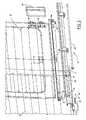
- FIG. 1is a perspective view of a heated sliding window assembly including a window frame, an actuator, and an electrical connection providing current to the heated defroster grid;
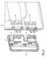
- FIG. 2is a partial exploded perspective view of the heated sliding window assembly including a portion of the fixed window and a portion of the sliding window including the rail, guide bracket and switch;
- FIG. 3is a partial perspective view of the heated sliding window assembly of FIG. 2 assembled
- FIG. 4is a side view of one embodiment of a switch and housing
- FIG. 5is an enlarged front view of a portion of the switch and housing of FIG. 4 ;
- FIG. 6is a side view of a wire clip that engages a rail of the heated sliding window assembly
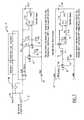
- FIG. 7is a schematic diagram of various circuit designs for a heated sliding window assembly that includes a relay and transistor;
- FIG. 8includes schematics of a wiring system for a heated sliding window assembly including a relay and transistors
- FIG. 9includes wiring schematics of a heated sliding window assembly including a transistor
- FIG. 10is a partial perspective view of a fixed widow including contacts and a contact cover
- FIG. 11is a partial perspective view of a fixed widow including contacts and a contact cover
- FIG. 12is a partial sectional view of a fixed widow including contacts and a contact cover.
- FIGS. 1-3there is shown one embodiment of a heated sliding window assembly 10 for a vehicle.
- the heated sliding window assembly 10may be utilized in various positions on a vehicle.
- the following detailed description of various embodimentswill be given with reference to a power heated sliding window assembly positioned in an opening in a back of a motor vehicle such that the window assembly includes a sliding window that slides horizontally within a window frame. It should be understood that various other orientations and movements may be utilized.
- the heated sliding window assembly 10may include a rail 12 that is attached to the vehicle.
- the rail 12may include a channel 14 formed therein.
- the rail 12may be attached to either an upper or lower portion of the window frame 16 with the rail 12 depicted on the lower portion of the frame 16 in FIG. 1 .
- a heated sliding window assembly 10may also include at least one fixed window 18 that is affixed to the vehicle.
- the fixed window 18may include an electrical contact 20 .
- a sliding window 22may be positioned in the rail 12 .
- the sliding window 22is moveable between open and closed positions.
- the sliding window 22may include an electrical contact 24 that engages and disengages the contact 20 attached to the at least one fixed window 18 in the closed and open positions respectively.
- the sliding windowmay also include a heater grid 25 .
- a drive mechanism 23may be linked with the sliding window 22 for moving the sliding window 22 between the open and closed positions.
- Various drive mechanisms 23may include pull-pull cable systems as well as other mechanized drive assemblies.
- An electrical circuitmay be provided for carrying current to the heater grid 19 .
- a switch 26may be included in the electrical circuit that cuts off current to the heater grid 19 when the sliding window 22 is moved.
- the switch 26 or a sensor 64 associated with the electrical circuitdetects movement of the sliding window 22 and provides a signal that cuts off electrical current that is routed to the contacts 20 , 24 on the fixed and sliding windows 18 , 22 before the contact 24 on the sliding window 22 disengages from the contact 20 on the fixed window 18 .
- the electrical current that is routed to the contacts 20 , 24maybe distributed through the fixed and sliding windows 18 , 22 to act as a defrost or fog clearing mechanism on a window assembly. As shown in the embodiment of FIG.
- the fixed and sliding windows 18 , 22include a heater grid 19 including a conducting element such as wires, a film, a conductive paint or various other types of elements positioned thereon that receive electrical current from a connection 28 and heat to remove fog or snow or ice or other materials from the fixed and sliding windows 18 , 22 .
- a heater grid 19including a conducting element such as wires, a film, a conductive paint or various other types of elements positioned thereon that receive electrical current from a connection 28 and heat to remove fog or snow or ice or other materials from the fixed and sliding windows 18 , 22 .
- the at least one fixed window 18includes two fixed windows 18 that are attached to the vehicle.
- the electrical currentis routed from the connection 28 to a first of the fixed windows 18 which is connected to the second fixed window 18 via a jumper cable 30 disposed below the rail 12 .
- the sliding window 22is connected to the second fixed window 18 via the electrical contact 20 on the fixed window 18 and the electrical contact 24 on the sliding window 22 . In this manner, electrical current is routed through the various fixed and sliding windows 18 , 22 to provide a heated sliding window assembly 10 .
- the heated sliding window assembly 10may include a magnet 32 that is attached to the sliding window 22 .
- the sliding window 22is positioned in a guide bracket 34 positioned in the channel 14 formed in the rail 12 .
- the guide bracket 34may include a slot 36 formed therein that receives the sliding window 22 .
- the guide bracket 34may include various formations 38 thereon, such as the legs extending from the guide bracket 34 , as depicted in FIG. 2 , which are positioned within the rail 12 and act as a guide for the lateral movement of the sliding window 22 within the rail 12 .
- the magnet 32is positioned in a slot 40 formed on an end of the guide bracket 34 within one of the formations 38 formed on the bottom of the guide bracket 34 .
- the contacts 20 , 24may include a cover 25 , as best shown in FIGS. 10 , 11 and 12 .
- the cover 25may be formed of any appropriate material including thermoplastic type materials.
- the electrical contacts 20 on the fixed window 18may include a raised surface 29 creating a space between the fixed window 18 and the contacts 20 .
- the contacts 20may also include a retention slot 33 .
- the cover 25may include retention legs 35 that are received by the raised surface 29 of the contacts 20 . As the retention legs 35 of the cover 25 are fully positioned in the raised surface 29 of the contacts 20 , a snap feature 37 of the retention legs 35 engages the retention slot 33 formed in the raised surface 29 , as best seen in FIG. 12 to complete the attachment of the cover 25 to the contacts 20 on the fixed window 18 .
- the switch 26may include a reed switch 42 that is attached to the rail 12 .
- the reed switch 42may include a housing 44 that has a dovetail slot 46 formed thereon, as best shown in FIGS. 4 and 5 .
- the dovetail slot 46may mate with a corresponding feature 48 formed on the rail 12 allowing the housing 44 to slide on the rail 12 .
- the housing 44may include a spring arm 50 again shown in FIGS. 4 and 5 that engages a notch 52 formed on the rail 12 to position the housing 44 on the rail 12 .
- the housing 44may also include a wire routing extension 54 for positioning a wire relative to the rail 12 . In this manner, the routing extension 54 positions the wire such that it is not pinched in the rail 12 or otherwise damaged when assembling the rail 12 and guide bracket 34 .
- the heated sliding window assembly 10may also include at least one wire clip 56 that is attached to the rail 12 for positioning wires associated with the heated sliding window assembly 10 .
- the wire clip 56may include a body 58 that has a dovetail slot 60 formed thereon that mates with the corresponding feature 48 formed on the guide rail 12 enabling the wire clip 56 to slide on the rail 12 .
- the body 58includes a hook shaped retaining section 62 for housing a wire.
- the electrical circuitmay include a Hall effect sensor 64 .
- the Hall effect sensor 64may be connected to a circuit including a power source 66 and a relay 68 providing current to the heated sliding window assembly 10 .
- the Hall effect sensor 64sends a signal to a transistor 70 linked with the relay 68 on a ground side of the heated sliding window assembly 10 to turn the transistor 70 on and off wherein the transistor completes or opens the circuit thereby cutting off electrical current to the contacts 20 , 24 .
- the transistor Q 2drives transistor Q 1 or the output transistor.
- the transistor 70is in series with the relay and the transistor is powered directly by the power source 66 .
- various transistorsmay be utilized including FETs, BJTs or other transistors.
- various resistors 72may be positioned relative to the transistors 70 to bias the transistors 70 as needed. Further, in the depicted embodiments of FIG. 7 the resistors 72 may have various values such that a change in the values may allow adaptations to a specific application. Various values of the resistors 72 may be utilized.
- FIG. 8there is shown another electrical circuit in which the Hall effect sensor 64 is connected to a circuit including a power source 66 and a relay 68 providing current to the heated sliding window assembly 10 .
- the Hall effect sensor 64sends a signal to the transistor 70 linked with the relay 68 on a ground side of the coil on relay 68 to turn the transistor 70 on and off wherein the transistor 70 completes or opens the circuit.
- the transistor 70completes the circuit for the relay coil which closes the relay contacts allowing current to flow to the heated sliding window assembly 10 .
- different resistors 72 and relays 68 as well as various types of transistors 70may be utilized. Again, the values of the resistors 72 of the depicted embodiments of FIG. 8 may be changed without departing from the invention to tailor the electrical system for specific applications.
- the Hall effect sensor 64is connected to a circuit having a power source 66 connected to the heated sliding window assembly 10 .
- the Hall effect sensor 64sends a signal to a transistor 70 linked with a ground side of the heated sliding window assembly 10 to turn the transistor 70 on and off wherein the transistor 70 completes or opens the circuit.
- FIGS. 7 and 8there are shown different schematics and resistors 72 to bias the various transistors 70 . It should be realized that the values of the resistors 72 and positioning of the various components may be changed to tailor the electrical system for a specific application.
- the Hall effect sensor 64may be interchanged with the reed switch 42 as described above.
- the reed switch 42may be connected on the ground or power side of the relay coil providing power to the heater grid 19 . Alternately, the reed switch 42 may be connected to provide a signal to a window heater grid controller 75 .
- the window heat grid controller 75would enable or disable power to the heater grid 19 based on the state of the reed switch 42 signal.
- the heated sliding window assembly 10may be assembled such that the guide bracket 34 is attached to the sliding window 22 .
- the guide bracket 34may be positioned in the rail 12 for movement between open and closed positions.
- the contacts 24 on the sliding window 22engage the contacts 20 on the at least one fixed window 18 when in the closed position.
- a magnet 32may be attached to the sliding window 22 such that it moves with the sliding window 22 .
- the reed switch 42 or a Hall effect sensor 64detects the magnetic field of the magnet 32 to determine movement of the sliding window 22 and cuts off electrical current routed to the contacts 20 , 24 . In this manner, electrical current is shut off prior to disengagement of the contacts 20 , 24 such that a arc or spark is not formed between the gap between the contacts 20 , as the sliding window 22 moves away from the at least one fixed window 18 .
Landscapes
- Engineering & Computer Science (AREA)
- Mechanical Engineering (AREA)
- Power-Operated Mechanisms For Wings (AREA)
Abstract
Description
Claims (17)
Priority Applications (3)
| Application Number | Priority Date | Filing Date | Title |
|---|---|---|---|
| US12/335,817US8707624B2 (en) | 2008-12-16 | 2008-12-16 | Heated sliding window assembly |
| CA2688675ACA2688675A1 (en) | 2008-12-16 | 2009-12-15 | Heated sliding window assembly |
| MX2009013841AMX2009013841A (en) | 2008-12-16 | 2009-12-16 | Heated sliding window assembly. |
Applications Claiming Priority (1)
| Application Number | Priority Date | Filing Date | Title |
|---|---|---|---|
| US12/335,817US8707624B2 (en) | 2008-12-16 | 2008-12-16 | Heated sliding window assembly |
Publications (2)
| Publication Number | Publication Date |
|---|---|
| US20100146859A1 US20100146859A1 (en) | 2010-06-17 |
| US8707624B2true US8707624B2 (en) | 2014-04-29 |
Family
ID=42238903
Family Applications (1)
| Application Number | Title | Priority Date | Filing Date |
|---|---|---|---|
| US12/335,817Active2030-05-11US8707624B2 (en) | 2008-12-16 | 2008-12-16 | Heated sliding window assembly |
Country Status (3)
| Country | Link |
|---|---|
| US (1) | US8707624B2 (en) |
| CA (1) | CA2688675A1 (en) |
| MX (1) | MX2009013841A (en) |
Cited By (2)
| Publication number | Priority date | Publication date | Assignee | Title |
|---|---|---|---|---|
| US20150052814A1 (en)* | 2009-08-06 | 2015-02-26 | Magna Mirrors Of America, Inc. | Slider window assembly |
| US10797374B1 (en) | 2019-06-17 | 2020-10-06 | Ford Global Technologies, Llc | Automotive glass antenna with fixed and moving portions |
Families Citing this family (32)
| Publication number | Priority date | Publication date | Assignee | Title |
|---|---|---|---|---|
| US8246101B2 (en)* | 2007-11-02 | 2012-08-21 | Dura Global Technologies, Llc | Flush drop-glass window module |
| US8402695B2 (en) | 2009-08-06 | 2013-03-26 | Magna Mirrors Of America, Inc. | Heated rear slider window assembly |
| US8938914B2 (en) | 2010-10-01 | 2015-01-27 | Magna Mirrors Of America, Inc. | Slider window assembly with cable guides |
| US10155432B2 (en) | 2010-10-18 | 2018-12-18 | Agc Automotive Americas Co. | Sliding window assembly |
| US10015842B2 (en)* | 2010-10-18 | 2018-07-03 | Agc Automotive Americans Co. | Sliding window assembly |
| US10015843B2 (en)* | 2010-10-18 | 2018-07-03 | Agc Automotive Americas Co. | Sliding window assembly |
| US20120117880A1 (en)* | 2010-11-11 | 2012-05-17 | Agc Automotive Americas Co. | Sliding window assembly for a vehicle |
| WO2012088287A1 (en) | 2010-12-22 | 2012-06-28 | Magna Mirrors Of America, Inc. | Slider window assembly |
| US9688122B2 (en) | 2011-05-20 | 2017-06-27 | Dura Operating, Llc | Motor vehicle window assembly with defrost |
| US9894717B2 (en)* | 2011-07-18 | 2018-02-13 | Pilkington Group Limited | Heated vehicle sliding window assembly |
| US20140238967A1 (en)* | 2013-02-26 | 2014-08-28 | Spartan Motors, Inc. | Heated moveable glass for vehicles |
| US9475364B2 (en) | 2013-10-14 | 2016-10-25 | Magna Mirrors Of America, Inc. | Sealing system for movable window of rear window assembly |
| US9579955B2 (en) | 2014-08-26 | 2017-02-28 | Magna Mirros Of America, Inc. | Rear slider window assembly with heated movable window |
| WO2016054027A1 (en) | 2014-09-29 | 2016-04-07 | Agc Automotive Americas R&D, Inc. | Sliding window assembly |
| US9731580B2 (en)* | 2014-10-29 | 2017-08-15 | Magna Mirrors Of America, Inc. | Slider window assembly with sensor |
| US10172185B2 (en)* | 2015-01-05 | 2019-01-01 | Ford Global Technologies, Llc | Selective heating of vehicle side window |
| US10023026B2 (en) | 2015-11-20 | 2018-07-17 | Magna Mirrors Of America, Inc. | Vehicle rear slider window assembly with enhanced rail attachment |
| US10266037B2 (en) | 2015-11-23 | 2019-04-23 | Magna Mirrors Of America, Inc. | Slider window assembly with two piece end stop |
| US10239397B2 (en) | 2015-11-24 | 2019-03-26 | Magna Mirrors Of America, Inc. | Sealing system for movable window of rear window assembly |
| US10524313B2 (en)* | 2017-02-09 | 2019-12-31 | Magna Mirrors Of America, Inc. | Rear slider window assembly with laminated heating element |
| GB2574640B (en)* | 2018-06-13 | 2020-12-02 | Ford Global Tech Llc | A system and method for heating a window |
| CN109367365B (en)* | 2018-10-18 | 2020-05-15 | 福耀玻璃工业集团股份有限公司 | Automobile rear gear sliding window assembly |
| CN109552252B (en)* | 2018-11-22 | 2022-04-22 | 重庆金康新能源汽车设计院有限公司 | Automobile door and window glass heater, automatic heating device and automatic heating method thereof |
| CN109835151B (en)* | 2019-03-04 | 2020-10-30 | 福耀玻璃工业集团股份有限公司 | Automobile sliding window with adjustable conductive tongue piece assembly |
| US11938793B2 (en) | 2019-03-14 | 2024-03-26 | Magna Mirrors Of America, Inc. | Sealing system for movable window of vehicular rear window assembly |
| EP3969303B1 (en)* | 2019-06-21 | 2024-11-27 | Gentex Corporation | Electrical connection method to movable window |
| US12054035B2 (en) | 2019-08-08 | 2024-08-06 | Magna Mirrors Of America, Inc. | Vehicular rear window assembly with continuous heater trace |
| CN113320363B (en)* | 2020-02-28 | 2022-12-16 | 伟巴斯特车顶供暖系统(上海)有限公司 | Vehicle skylight with electrified skylight glass and vehicle |
| US11912110B2 (en) | 2020-06-05 | 2024-02-27 | Magna Mirrors Of America, Inc. | Sealing system for movable window of vehicular rear slider window assembly |
| US11686144B2 (en) | 2021-02-24 | 2023-06-27 | Magna Mirrors Of America, Inc. | Slider window assembly with switch device |
| US12193122B2 (en)* | 2021-03-11 | 2025-01-07 | Magna Mirrors Of America, Inc. | Vehicular window assembly with solderless electrical connection to heater grid |
| CN116442739A (en)* | 2023-05-10 | 2023-07-18 | 重庆长安汽车股份有限公司 | A sunroof assembly and vehicle |
Citations (24)
| Publication number | Priority date | Publication date | Assignee | Title |
|---|---|---|---|---|
| US4410843A (en)* | 1981-03-25 | 1983-10-18 | Saint-Gobain Vitrage | Electrically controlled sliding window and proximity detector |
| US4415196A (en)* | 1980-02-07 | 1983-11-15 | Saint-Gobain Vitrage | Glass with conductive strips for supplying windshield wiper |
| US4458445A (en)* | 1981-03-25 | 1984-07-10 | Saint-Gobain Vitrage | Sliding electrically moved window provided with a safety detector |
| US5363596A (en)* | 1994-03-07 | 1994-11-15 | Chardon Rubber Company | Seal assembly for a sliding window |
| US5531046A (en)* | 1995-06-02 | 1996-07-02 | General Motors Corporation | Power sliding window assembly |
| US5724769A (en)* | 1995-01-06 | 1998-03-10 | Excell Industries, Inc. | Motor vehicle window construction with pull-pull cable system |
| US5822922A (en)* | 1996-03-29 | 1998-10-20 | Excel Industries, Inc. | Power drive system for modular dual pane rear-mounted window assembly |
| US5836110A (en)* | 1996-03-29 | 1998-11-17 | Excel Industries, Inc. | Remote manual anti-backdrive system for modular rear-mounted window assembly |
| US6014840A (en)* | 1997-12-24 | 2000-01-18 | Dura Automotive Systems, Inc. | Heated sliding window assembly with an electrically connected sliding pane |
| US6026611A (en)* | 1999-05-25 | 2000-02-22 | Dura Automotive Systems, Inc. | Power sliding window assembly |
| US6125585A (en)* | 1999-08-16 | 2000-10-03 | Hi-Lex Corporation | Sliding window regulator |
| US6223470B1 (en)* | 1999-09-20 | 2001-05-01 | Dura Global Technologies, Inc. | Dropglass window module |
| US6324788B1 (en)* | 2000-02-04 | 2001-12-04 | Hi-Lex Corporation | Sliding window regulator with disconnectable power feature |
| US6490832B1 (en)* | 1996-03-01 | 2002-12-10 | Geze Gmbh & Co. | Sliding door system |
| US6591552B1 (en)* | 2000-08-14 | 2003-07-15 | Donnelly Corporation | Power slider window assembly |
| US6598931B2 (en)* | 2001-07-03 | 2003-07-29 | Honda Giken Kogyo Kabushiki Kaisha | Conductive wires protection case construction on rear glass in convertible top |
| US20040020131A1 (en)* | 2002-04-12 | 2004-02-05 | Jim Galer | Slider window assembly |
| US6766617B2 (en)* | 2002-08-12 | 2004-07-27 | Dura Global Technologies, Inc. | Power sliding rear window |
| US7003916B2 (en)* | 2002-04-01 | 2006-02-28 | Donnelly Corporation | Horizontal slider window assembly |
| US7073293B2 (en)* | 2002-10-30 | 2006-07-11 | Donnelly Corporation | Horizontal slider window assembly |
| US20070277443A1 (en)* | 2006-02-06 | 2007-12-06 | Pyramid Specialty Products Ltd. | Motorized sliding window pane |
| US20080100152A1 (en)* | 2004-10-17 | 2008-05-01 | Dorma Gmbh & Co. Kg | Sliding Door Comprising a Magnetic Support and/or Drive System Comprising a Row of Magnets |
| US20080122262A1 (en)* | 2006-08-21 | 2008-05-29 | Dura Automotive Systems, Inc. | Multi-Pane Window Assembly With Two-Sided Frame |
| US20080202032A1 (en)* | 2005-07-08 | 2008-08-28 | Ceta Elektromechanik Gmbh | Guiding Mechanism for Sliding Leaves or Sliding Doors |
- 2008
- 2008-12-16USUS12/335,817patent/US8707624B2/enactiveActive
- 2009
- 2009-12-15CACA2688675Apatent/CA2688675A1/ennot_activeAbandoned
- 2009-12-16MXMX2009013841Apatent/MX2009013841A/enactiveIP Right Grant
Patent Citations (25)
| Publication number | Priority date | Publication date | Assignee | Title |
|---|---|---|---|---|
| US4415196A (en)* | 1980-02-07 | 1983-11-15 | Saint-Gobain Vitrage | Glass with conductive strips for supplying windshield wiper |
| US4410843A (en)* | 1981-03-25 | 1983-10-18 | Saint-Gobain Vitrage | Electrically controlled sliding window and proximity detector |
| US4458445A (en)* | 1981-03-25 | 1984-07-10 | Saint-Gobain Vitrage | Sliding electrically moved window provided with a safety detector |
| US5363596A (en)* | 1994-03-07 | 1994-11-15 | Chardon Rubber Company | Seal assembly for a sliding window |
| US5724769A (en)* | 1995-01-06 | 1998-03-10 | Excell Industries, Inc. | Motor vehicle window construction with pull-pull cable system |
| US5531046A (en)* | 1995-06-02 | 1996-07-02 | General Motors Corporation | Power sliding window assembly |
| US6490832B1 (en)* | 1996-03-01 | 2002-12-10 | Geze Gmbh & Co. | Sliding door system |
| US5822922A (en)* | 1996-03-29 | 1998-10-20 | Excel Industries, Inc. | Power drive system for modular dual pane rear-mounted window assembly |
| US5836110A (en)* | 1996-03-29 | 1998-11-17 | Excel Industries, Inc. | Remote manual anti-backdrive system for modular rear-mounted window assembly |
| US6014840A (en)* | 1997-12-24 | 2000-01-18 | Dura Automotive Systems, Inc. | Heated sliding window assembly with an electrically connected sliding pane |
| US6026611A (en)* | 1999-05-25 | 2000-02-22 | Dura Automotive Systems, Inc. | Power sliding window assembly |
| US6125585A (en)* | 1999-08-16 | 2000-10-03 | Hi-Lex Corporation | Sliding window regulator |
| US6223470B1 (en)* | 1999-09-20 | 2001-05-01 | Dura Global Technologies, Inc. | Dropglass window module |
| US6324788B1 (en)* | 2000-02-04 | 2001-12-04 | Hi-Lex Corporation | Sliding window regulator with disconnectable power feature |
| US6591552B1 (en)* | 2000-08-14 | 2003-07-15 | Donnelly Corporation | Power slider window assembly |
| US6955009B2 (en)* | 2000-08-14 | 2005-10-18 | Donnelly Corporation | Power slider window assembly |
| US6598931B2 (en)* | 2001-07-03 | 2003-07-29 | Honda Giken Kogyo Kabushiki Kaisha | Conductive wires protection case construction on rear glass in convertible top |
| US7003916B2 (en)* | 2002-04-01 | 2006-02-28 | Donnelly Corporation | Horizontal slider window assembly |
| US20040020131A1 (en)* | 2002-04-12 | 2004-02-05 | Jim Galer | Slider window assembly |
| US6766617B2 (en)* | 2002-08-12 | 2004-07-27 | Dura Global Technologies, Inc. | Power sliding rear window |
| US7073293B2 (en)* | 2002-10-30 | 2006-07-11 | Donnelly Corporation | Horizontal slider window assembly |
| US20080100152A1 (en)* | 2004-10-17 | 2008-05-01 | Dorma Gmbh & Co. Kg | Sliding Door Comprising a Magnetic Support and/or Drive System Comprising a Row of Magnets |
| US20080202032A1 (en)* | 2005-07-08 | 2008-08-28 | Ceta Elektromechanik Gmbh | Guiding Mechanism for Sliding Leaves or Sliding Doors |
| US20070277443A1 (en)* | 2006-02-06 | 2007-12-06 | Pyramid Specialty Products Ltd. | Motorized sliding window pane |
| US20080122262A1 (en)* | 2006-08-21 | 2008-05-29 | Dura Automotive Systems, Inc. | Multi-Pane Window Assembly With Two-Sided Frame |
Cited By (7)
| Publication number | Priority date | Publication date | Assignee | Title |
|---|---|---|---|---|
| US20150052814A1 (en)* | 2009-08-06 | 2015-02-26 | Magna Mirrors Of America, Inc. | Slider window assembly |
| US9242533B2 (en)* | 2009-08-06 | 2016-01-26 | Magna Mirrors Of America, Inc. | Slider window assembly |
| US9642187B2 (en) | 2009-08-06 | 2017-05-02 | Magna Mirrors Of America, Inc. | Slider window assembly |
| US10219324B2 (en) | 2009-08-06 | 2019-02-26 | Magna Mirrors Of America, Inc. | Rear slider window assembly |
| US10841983B2 (en) | 2009-08-06 | 2020-11-17 | Magna Mirrors Of America, Inc. | Rear slider window assembly |
| US11425798B2 (en)* | 2009-08-06 | 2022-08-23 | Magna Mirrors Of America, Inc. | Rear slider window assembly |
| US10797374B1 (en) | 2019-06-17 | 2020-10-06 | Ford Global Technologies, Llc | Automotive glass antenna with fixed and moving portions |
Also Published As
| Publication number | Publication date |
|---|---|
| US20100146859A1 (en) | 2010-06-17 |
| MX2009013841A (en) | 2010-06-18 |
| CA2688675A1 (en) | 2010-06-16 |
Similar Documents
| Publication | Publication Date | Title |
|---|---|---|
| US8707624B2 (en) | Heated sliding window assembly | |
| US9624707B2 (en) | Heated sliding window assembly | |
| US6014840A (en) | Heated sliding window assembly with an electrically connected sliding pane | |
| US9579955B2 (en) | Rear slider window assembly with heated movable window | |
| CA1309742C (en) | Sliding roof panel control apparatus | |
| US8400240B2 (en) | Magnetic switching device | |
| US11318818B2 (en) | Window regulator with power supply connection for electrical device on movable glass | |
| US20130019532A1 (en) | Heated vehicle sliding window assembly | |
| US20070199243A1 (en) | Removable access gate for parking lots | |
| WO2012065111A1 (en) | Sliding window assembly | |
| US12065023B2 (en) | Vehicular rear slider window assembly with retaining element | |
| US20230084191A1 (en) | Vehicular rear slider window assembly with electrical connection to movable panel heater grid | |
| US20180215242A1 (en) | Sliding roof system for a motor vehicle | |
| CA2746465A1 (en) | Drive system for a door | |
| JP3862991B2 (en) | Electric stepping device for automobile | |
| CN115087789A (en) | Assembly of an adjusting device of a motor vehicle | |
| JPH0658616A (en) | Ventilator | |
| US9061660B2 (en) | Device for cleansing door glass of vehicle | |
| US11952820B1 (en) | Slider window assembly with movable panel drive system | |
| JPH03132421A (en) | Automotive sun visor | |
| KR100534341B1 (en) | Device for supplying the power to sliding door of vehicle | |
| US8024893B2 (en) | Powered slider drive interface and drive assembly | |
| JP2000234470A (en) | Power-supply mechanism to slide door | |
| CN104832011A (en) | Door handle covering device, door and vehicle | |
| CN212765632U (en) | Electric control automobile curtain |
Legal Events
| Date | Code | Title | Description |
|---|---|---|---|
| AS | Assignment | Owner name:DURA GLOBAL TECHNOLOGIES, INC.,MICHIGAN Free format text:ASSIGNMENT OF ASSIGNORS INTEREST;ASSIGNORS:GIPSON, RONNIE G.;FLYNN, CHARLES;HOWE, BRIAN D.;AND OTHERS;SIGNING DATES FROM 20090116 TO 20090119;REEL/FRAME:022131/0297 Owner name:DURA GLOBAL TECHNOLOGIES, INC., MICHIGAN Free format text:ASSIGNMENT OF ASSIGNORS INTEREST;ASSIGNORS:GIPSON, RONNIE G.;FLYNN, CHARLES;HOWE, BRIAN D.;AND OTHERS;SIGNING DATES FROM 20090116 TO 20090119;REEL/FRAME:022131/0297 | |
| AS | Assignment | Owner name:WACHOVIA CAPITAL FINANCE CORPORATION (CENTRAL),ILL Free format text:SECURITY AGREEMENT;ASSIGNOR:DURA GLOBAL TECHNOLOGIES, INC.;REEL/FRAME:023957/0946 Effective date:20100121 Owner name:WACHOVIA CAPITAL FINANCE CORPORATION (CENTRAL), IL Free format text:SECURITY AGREEMENT;ASSIGNOR:DURA GLOBAL TECHNOLOGIES, INC.;REEL/FRAME:023957/0946 Effective date:20100121 | |
| AS | Assignment | Owner name:PATRIARCH PARTNERS AGENCY SERVICES, LLC,NEW YORK Free format text:SECURITY AGREEMENT;ASSIGNORS:DURA OPERATING CORP.;ATWOOD MOBILE PRODUCTS, INC.;DURA AUTOMOTIVE SYSTEMS, INC.;AND OTHERS;REEL/FRAME:024055/0001 Effective date:20100121 Owner name:PATRIARCH PARTNERS AGENCY SERVICES, LLC, NEW YORK Free format text:SECURITY AGREEMENT;ASSIGNORS:DURA OPERATING CORP.;ATWOOD MOBILE PRODUCTS, INC.;DURA AUTOMOTIVE SYSTEMS, INC.;AND OTHERS;REEL/FRAME:024055/0001 Effective date:20100121 | |
| AS | Assignment | Owner name:DEUTSCHE BANK TRUST COMPANY AMERICAS,NEW YORK Free format text:SECURITY AGREEMENT;ASSIGNORS:DURA OPERATING CORP.;ATWOOD MOBILE PRODUCTS, INC.;DURA AUTOMOTIVE SYSTEMS, INC.;AND OTHERS;REEL/FRAME:024195/0001 Effective date:20100121 Owner name:DEUTSCHE BANK TRUST COMPANY AMERICAS, NEW YORK Free format text:SECURITY AGREEMENT;ASSIGNORS:DURA OPERATING CORP.;ATWOOD MOBILE PRODUCTS, INC.;DURA AUTOMOTIVE SYSTEMS, INC.;AND OTHERS;REEL/FRAME:024195/0001 Effective date:20100121 | |
| AS | Assignment | Owner name:WILMINGTON TRUST (LONDON) LIMITED,UNITED KINGDOM Free format text:SECURITY AGREEMENT;ASSIGNORS:DURA OPERATING CORP.;ATWOOD MOBILE PRODUCTS, INC.;DURA AUTOMOTIVE SYSTEMS, INC.;AND OTHERS;REEL/FRAME:024244/0282 Effective date:20100121 Owner name:WILMINGTON TRUST (LONDON) LIMITED, UNITED KINGDOM Free format text:SECURITY AGREEMENT;ASSIGNORS:DURA OPERATING CORP.;ATWOOD MOBILE PRODUCTS, INC.;DURA AUTOMOTIVE SYSTEMS, INC.;AND OTHERS;REEL/FRAME:024244/0282 Effective date:20100121 | |
| AS | Assignment | Owner name:DURA GLOBAL TECHNOLOGIES, LLC, MICHIGAN Free format text:CONVERSION TO LLC;ASSIGNOR:DURA GLOBAL TECHNOLOGIES, INC.;REEL/FRAME:032499/0381 Effective date:20100121 Owner name:DURA OPERATING, LLC, MICHIGAN Free format text:MERGER;ASSIGNOR:DURA GLOBAL TECHNOLOGIES, LLC;REEL/FRAME:032499/0446 Effective date:20120919 | |
| STCF | Information on status: patent grant | Free format text:PATENTED CASE | |
| FEPP | Fee payment procedure | Free format text:SURCHARGE FOR LATE PAYMENT, LARGE ENTITY (ORIGINAL EVENT CODE: M1554) | |
| MAFP | Maintenance fee payment | Free format text:PAYMENT OF MAINTENANCE FEE, 4TH YEAR, LARGE ENTITY (ORIGINAL EVENT CODE: M1551) Year of fee payment:4 | |
| AS | Assignment | Owner name:DUS OPERATING INC., MICHIGAN Free format text:ASSIGNMENT OF ASSIGNORS INTEREST;ASSIGNOR:DURA OPERATING, LLC;REEL/FRAME:055131/0001 Effective date:20200605 | |
| AS | Assignment | Owner name:WELLS FARGO BANK, NATIONAL ASSOCIATION, AS AGENT, ILLINOIS Free format text:SECURITY AGREEMENT;ASSIGNOR:DUS OPERATING INC.;REEL/FRAME:055228/0843 Effective date:20210205 Owner name:BLUE TORCH FINANCE LLC, AS COLLATERAL AGENT, NEW YORK Free format text:PATENT AND TRADEMARK SECURITY AGREEMENT;ASSIGNORS:DURA AUTOMOTIVE HOLDINGS U.K., LTD;DURA AUTOMOTIVE SYSTEMS GMBH;DUS OPERATING INC.;REEL/FRAME:055224/0756 Effective date:20210205 | |
| MAFP | Maintenance fee payment | Free format text:PAYMENT OF MAINTENANCE FEE, 8TH YEAR, LARGE ENTITY (ORIGINAL EVENT CODE: M1552); ENTITY STATUS OF PATENT OWNER: LARGE ENTITY Year of fee payment:8 | |
| AS | Assignment | Owner name:DUS OPERATING, INC., MICHIGAN Free format text:RELEASE OF PATENT AND TRADEMARK SECURITY AGREEMENT;ASSIGNOR:BLUE TORCH FINANCE LLC;REEL/FRAME:058671/0253 Effective date:20220103 Owner name:DURA AUTOMOTIVE SYSTEMS GMBH, GERMANY Free format text:RELEASE OF PATENT AND TRADEMARK SECURITY AGREEMENT;ASSIGNOR:BLUE TORCH FINANCE LLC;REEL/FRAME:058671/0253 Effective date:20220103 Owner name:DURA AUTOMOTIVE HOLDINGS U.K., LTD, UNITED KINGDOM Free format text:RELEASE OF PATENT AND TRADEMARK SECURITY AGREEMENT;ASSIGNOR:BLUE TORCH FINANCE LLC;REEL/FRAME:058671/0253 Effective date:20220103 | |
| AS | Assignment | Owner name:DUS OPERATING INC., MICHIGAN Free format text:RELEASE BY SECURED PARTY;ASSIGNOR:WELLS FARGO BANK, NATIONAL ASSOCIATION;REEL/FRAME:059783/0288 Effective date:20220413 | |
| AS | Assignment | Owner name:PLASMAN US HOLDCO LLC, CANADA Free format text:ASSIGNMENT OF ASSIGNORS INTEREST;ASSIGNORS:DUS OPERATING INC.;DURA AUTOMOTIVE HOLDINGS U.K. LTD;DURA AUTOMOTIVE BODY & GLASS SYSTEMS GMBH;REEL/FRAME:061476/0893 Effective date:20220909 |