US8707488B2 - Multiple configuration air mattress pump system - Google Patents
Multiple configuration air mattress pump systemDownload PDFInfo
- Publication number
- US8707488B2 US8707488B2US12/907,723US90772310AUS8707488B2US 8707488 B2US8707488 B2US 8707488B2US 90772310 AUS90772310 AUS 90772310AUS 8707488 B2US8707488 B2US 8707488B2
- Authority
- US
- United States
- Prior art keywords
- air
- pump system
- pump
- zones
- manifold
- Prior art date
- Legal status (The legal status is an assumption and is not a legal conclusion. Google has not performed a legal analysis and makes no representation as to the accuracy of the status listed.)
- Active, expires
Links
- 230000004913activationEffects0.000claims2
- 238000004519manufacturing processMethods0.000description8
- 238000012360testing methodMethods0.000description6
- 230000008901benefitEffects0.000description4
- 238000004806packaging method and processMethods0.000description4
- 238000013461designMethods0.000description3
- 238000000034methodMethods0.000description2
- 238000003860storageMethods0.000description2
- 239000000853adhesiveSubstances0.000description1
- 230000001070adhesive effectEffects0.000description1
- 230000000712assemblyEffects0.000description1
- 238000000429assemblyMethods0.000description1
- 230000000903blocking effectEffects0.000description1
- 238000009530blood pressure measurementMethods0.000description1
- 230000008859changeEffects0.000description1
- 230000001276controlling effectEffects0.000description1
- 230000007423decreaseEffects0.000description1
- 238000011161developmentMethods0.000description1
- 230000010354integrationEffects0.000description1
- 238000003754machiningMethods0.000description1
- 230000007246mechanismEffects0.000description1
- 238000012986modificationMethods0.000description1
- 230000004048modificationEffects0.000description1
- 238000012856packingMethods0.000description1
- 230000008569processEffects0.000description1
- 230000001105regulatory effectEffects0.000description1
- 238000012956testing procedureMethods0.000description1
- 238000012549trainingMethods0.000description1
- 238000003466weldingMethods0.000description1
Images


Classifications
- F—MECHANICAL ENGINEERING; LIGHTING; HEATING; WEAPONS; BLASTING
- F04—POSITIVE - DISPLACEMENT MACHINES FOR LIQUIDS; PUMPS FOR LIQUIDS OR ELASTIC FLUIDS
- F04B—POSITIVE-DISPLACEMENT MACHINES FOR LIQUIDS; PUMPS
- F04B45/00—Pumps or pumping installations having flexible working members and specially adapted for elastic fluids
- F04B45/04—Pumps or pumping installations having flexible working members and specially adapted for elastic fluids having plate-like flexible members, e.g. diaphragms
- A—HUMAN NECESSITIES
- A47—FURNITURE; DOMESTIC ARTICLES OR APPLIANCES; COFFEE MILLS; SPICE MILLS; SUCTION CLEANERS IN GENERAL
- A47C—CHAIRS; SOFAS; BEDS
- A47C27/00—Spring, stuffed or fluid mattresses or cushions specially adapted for chairs, beds or sofas
- A47C27/08—Fluid mattresses
- A47C27/081—Fluid mattresses of pneumatic type
- A47C27/082—Fluid mattresses of pneumatic type with non-manual inflation, e.g. with electric pumps
- F—MECHANICAL ENGINEERING; LIGHTING; HEATING; WEAPONS; BLASTING
- F04—POSITIVE - DISPLACEMENT MACHINES FOR LIQUIDS; PUMPS FOR LIQUIDS OR ELASTIC FLUIDS
- F04B—POSITIVE-DISPLACEMENT MACHINES FOR LIQUIDS; PUMPS
- F04B39/00—Component parts, details, or accessories, of pumps or pumping systems specially adapted for elastic fluids, not otherwise provided for in, or of interest apart from, groups F04B25/00 - F04B37/00
- F04B39/12—Casings; Cylinders; Cylinder heads; Fluid connections
- F04B39/121—Casings
- F—MECHANICAL ENGINEERING; LIGHTING; HEATING; WEAPONS; BLASTING
- F04—POSITIVE - DISPLACEMENT MACHINES FOR LIQUIDS; PUMPS FOR LIQUIDS OR ELASTIC FLUIDS
- F04B—POSITIVE-DISPLACEMENT MACHINES FOR LIQUIDS; PUMPS
- F04B39/00—Component parts, details, or accessories, of pumps or pumping systems specially adapted for elastic fluids, not otherwise provided for in, or of interest apart from, groups F04B25/00 - F04B37/00
- F04B39/12—Casings; Cylinders; Cylinder heads; Fluid connections
- F04B39/123—Fluid connections
- Y—GENERAL TAGGING OF NEW TECHNOLOGICAL DEVELOPMENTS; GENERAL TAGGING OF CROSS-SECTIONAL TECHNOLOGIES SPANNING OVER SEVERAL SECTIONS OF THE IPC; TECHNICAL SUBJECTS COVERED BY FORMER USPC CROSS-REFERENCE ART COLLECTIONS [XRACs] AND DIGESTS
- Y10—TECHNICAL SUBJECTS COVERED BY FORMER USPC
- Y10T—TECHNICAL SUBJECTS COVERED BY FORMER US CLASSIFICATION
- Y10T137/00—Fluid handling
- Y10T137/8593—Systems
- Y10T137/85978—With pump
- Y10T137/86035—Combined with fluid receiver
Definitions
- This inventionrelates generally to the field of air mattresses. More specifically, it relates to a pump system that can be used with mattresses having a varying number of individually-inflatable zones.
- the pump systemhas a common platform and a manifold that can accommodate a range of pump sizes, differing numbers of air control valves, and varied configurations of faceplates for easy and cost-effective manufacturing and use with mattresses that have different numbers of inflatable zones.
- a multiple configuration systemalso allows for streamlined testing procedures and lower testing costs, such as standard durability drop tests, form, fit and function tests, and compliance tests across the configurations.
- the standardized pump systemsalso allow for use of the same packaging for each pump system, including both the inner packaging and outer shipping box, fewer inventory SKUs, standardized packaging lines, processes and employee training, and standardized pallet size and storage requirements.
- the present inventionprovides a multiple configuration mattress pump.
- the pump systemincludes a manifold which is adapted to connect a varying number of air control valves to control air flow to the related number of inflatable mattress zones.
- the platformcan accommodate a variety of pump sizes. Additionally, the platform is adapted to easily hold changeable faceplates containing a number of tube holes corresponding to the number of mattress zones. The number of plugs used to fill the holes in the manifold for unused air control valves for use with beds having fewer than the maximum number of zones can vary.
- the pump systemincludes a circuit board which fits onto the platform, the software of which can be programmed to match the number of air control valves corresponding to each inflatable zone.
- the inventionmay include a wired or wireless pendant connected to the circuit board of the platform, allowing the user to control the airflow in each inflatable zone.
- the inventionmay also include a pony board with a number of connection ports equal to the maximum number of air control openings in the manifold, with the output wires contained in a single arm and allowing for a single connection from the valves to the circuit board where multiple valves are used.
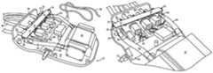
- FIG. 1is a side perspective view of an air mattress pump system in accordance with one embodiment of the present invention shown without an enclosure top and with certain details removed;
- FIG. 2is a top view of a pump system in accordance with one embodiment of the present invention shown without an enclosure top;
- FIG. 3is a detail side perspective view of a pump system in accordance with one embodiment of the present invention shown without an enclosure top;
- FIG. 4is a front perspective view of a manifold, air control valves, a pony board and an air pump in accordance with one embodiment of the present invention
- FIG. 5is a front perspective view of three configurations of pump systems with enclosure tops
- FIG. 6is a top view of the three configurations of pump systems of FIG. 5 , shown without enclosure tops;
- FIG. 7is a rear perspective view of a manifold and a faceplate in a two-zone configuration of a pump system
- FIG. 8is a rear perspective view of a manifold and faceplate in a six-zone configuration of a pump system
- FIG. 9is a front perspective view of a manifold, zone tubing and faceplates of two configurations of pump systems shown without enclosure tops;
- FIG. 10is a rear view of a manifold with an air control valve and air control plugs in accordance with one embodiment of the present invention.
- FIG. 11is a top perspective view of an air control valve in accordance with one embodiment of the present invention.
- FIG. 12is a top view of a platform of a pump system in accordance with one embodiment of the present invention.
- FIG. 13is an underside view of a top enclosure of a pump system in accordance with one embodiment of the present invention.
- FIG. 14is a top view of a manifold, a pony board, air valves, and air valve connective wires in accordance with one embodiment of the present invention
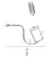
- FIG. 15is a side perspective view of a manifold and tubing of a pump system in accordance with one embodiment of the present invention.
- FIG. 16is a side perspective view of a pendant circuit board in accordance with one embodiment of the present invention, shown with the cover removed;
- FIG. 17is a side perspective view of a pendant attached to a pump system with an enclosure top in accordance with one embodiment of the present invention.
- FIGS. 1-6are views of a multiple configuration airbed pump system 10 in accordance with a preferred embodiment of the present invention.
- the pump system 10may include a pump casing consisting of a platform 20 and an enclosure top 80 .
- the systemmay further include a manifold 30 for controlling airflow and including air valves 35 and a pressure management valve 37 , air control valves 34 , air control plugs 36 , zone tubing 38 , a pump mounting area 40 for receiving a pump 42 , an interchangeable faceplate 50 , a primary circuit board 60 , internal tubing 62 , a pressure management tube 66 and a pendant 70 .
- the platform 20 , manifold 30 , zone tubing 38 , mounting base 40 , circuit board 60 , internal tubing 62 , pressure management tube 66 , pendant 70 and enclosure top 80are the shared components of the system, and can be used with mattresses varying from one to six individual inflatable zones.
- the system 10could be used with mattresses having other numbers of zones if desired by modifying the manifold 30 to include additional air valves 35 .
- the faceplate 50 , number of air control valves 34 and number of air control plugs 36are the only components that vary in the use of the system 10 with different mattresses.
- the software of the circuit board 60can be programmed to correspond to the number of zones to be inflated.
- the manifold 30 and circuit board 60can be mounted to the platform 20 , and the platform 20 may have a pump area 40 for holding a pump 42 .
- the use of a manifold 30is well-known in the art as a component for regulating air flow pumped from a pump 42 to air chambers. A diaphragm pump is shown, but other types of pumps could be used.
- the platform 20can also include a slot 52 for holding an changeable faceplate 50 .
- the platform 20may also include screw holes 22 for attaching the manifold 30 , circuit board 60 , and pump 42 , as well as for attaching the enclosure top 80 ( FIG. 11 ). Of course, other means of attaching the enclosure top 80 to the platform 20 , such as adhesives, sonic welding, or snap-fitting, may also be used.
- the assembled pump system 10 with the enclosure top 80 secured to the platform 20is identical for pump systems 10 used with, for example, six-, four-, and two-zone mattresses, with the exception of the faceplate 50 and number of zone tubes 38 exiting the faceplate 50 .
- Thisallows continuity in the overall product line, in addition to the cost savings, in using such an interchangeable pump system 10 .
- the casing platform 20 and enclosure top 80FIGS. 12-13
- the standardized platform 20 and enclosure top 80 casingalso allow for standardized packing, shipping, and storage of the pump systems 10 to be used with the varying mattress models.
- the standardized casingalso provides brand equity by keeping the same overall look across multiple price points and SKUs, and also provides packaging and advertising cost savings.
- one side of a manifold 30includes air control holes 32 .
- seven air control holes 32are shown. This allows up to seven air control valves 34 to be inserted into the holes 32 of the manifold 30 for a six-zone mattress, with six air control valves 34 used for air flow to the zones, and one air control valve 34 for exhaust. Solenoid valves ( FIG. 11 ) are shown but other types of air control valves 34 could be used.
- manifolds 30 with more or fewer air control holes 32could be manufactured to accommodate mattresses with more or fewer than six inflatable zones.
- the manifold 30includes a cover 31 which can be connected with screws using manifold screw holes 33 .
- FIG. 7shows a system 10 configured for a two-zone mattress, with the manifold 30 having three air control valves 34 and four air control plugs 36 blocking the unused holes 32 .
- FIG. 8shows a system 10 configured for a six-zone mattress, with the manifold 30 having seven air control valves 34 and therefore no air control plugs 36 .
- the air control plugs 36( FIG. 10 ) fit any hole 32 in the manifold 30 and are very inexpensive to manufacture; having these air control plugs 36 as one of the variable components therefore allows for only a small cost to change the configuration for use with different mattress models. It also allows for volume discounts, in that the same parts can be used across different SKUs.
- two air valves 35are connected by internal tubing 62 to the pump 42 , whereby air is pumped from the pump 42 to the manifold 30 .
- air valves 35are coupled to each of the seven holes 32 .
- a zone tube 38is attached to the air valve 35 opposite an air control valve 34 and runs to an inflatable zone of the mattress.
- the manifold 30is one of the more difficult and expensive components to tool for manufacturing, but, by simply plugging any unused holes 32 with plugs 36 , the manifold 30 can be used with beds ranging from, in the embodiment shown in the FIGS., one to six inflatable zones without any additional manufacturing or machining costs.
- the faceplate 50includes openings 54 through which the zone tubes 38 can pass.
- the faceplate 50fits into a slot 52 in the casing platform 20 and top enclosure 80 .
- Faceplates 50can therefore be changed to accommodate the number of zone tubes 38 (and air control valves 34 ) corresponding to the number of inflatable zones in each particular mattress.
- a faceplate 50 with four openings 54would be placed in the slot 52 , and four tubes 38 would run from the air valves 35 opposite the air control valves 34 , through the openings 54 and to each zone of the mattress.
- the faceplates 50are a small and inexpensive component of the pump 10 , and requiring only this component to be manufactured differently for use of the pump 10 with different mattresses saves time and money. Additionally, the faceplate 50 protects the tube 38 connections to the air valves 35 . Some pump systems currently on the market have the tube connections exposed, which subjects the existing pump systems to a greater risk of breakage. This “hiding” of the internal components in the pump system 10 of the present invention also adds aesthetic value to the system 10 giving it an overall clean, finished look.
- the platform 20 in a preferred embodimentalso includes a pump mounting area 40 for supporting a pump 42 .
- a diaphragm pumpis shown, but other types of air pumps could also be used.
- the mounting area 40 in the embodiment shown in FIG. 12includes four pump screw holes 44 by which the pump 42 can be secured. Of course, the mounting area 40 could be configured differently and include a different number and configuration of pump screw holes 44 depending on the pump 42 used. Alternative methods of securing the pump 42 to the mounting area 40 of the platform 20 could also be used.
- the mounting area 40is sized such that a variety of types and sizes of pumps 42 can be used with the pump system 10 .
- Internal tubing 62connects the pump 42 to the manifold 30 to pump air from the manifold 30 to the mattress zones.
- a circuit board 60may also be affixed to the platform 20 .
- the circuit board 60contains software programmable for the varying number of zones to be inflated. It also contains all connection assemblies for system power and for the pendant 70 used by the mattress user to control the inflation of the zones.
- the air control valves 34can be connected to the circuit board 60 by connective wires 64 , and air flow is controlled by the user selecting desired firmness on the pendant 70 which is connected to the circuit board 60 . This allows the corresponding amount of air to be pumped to each zone based on the firmness level selected by the user on the pendant 70 .
- a pressure measurement tube 66connects a pressure management valve 37 on the manifold 30 to the circuit board 60 to allow the software to determine the pressure in the manifold 30 to control the proper release of air for the firmness selected by the user.
- the circuit board 60can be used for any configuration of air control valves 34 and pump sizes 42 by loading it with the appropriate software program.
- a power cord 68may be attached to the circuit board 60 to provide power to the pump system 10 .
- the power cord 68may alternatively be attached through a transformer (not shown) depending on circuitry design. In a preferred embodiment, the power cord 68 passes through the top enclosure 80 and/or the platform 20 of the casing.
- a pendant 70can be connected to the circuit board 60 via a pendant cord 72 .
- An aperture 74 in the enclosure top 80allows the pendant cord 72 to pass through the enclosure top 80 for connection to the circuit board 60 .
- the pendant 70may be configured with the circuit board 60 for wireless control of the pump system 10 (not shown).
- the pendant 70includes a pendant circuit board 76 onto which pendant software is uploaded.
- the pendant 70 and pendant softwareare standard and can be can be used in connection with any pump system 10 configuration; the pendant 70 and pendant software are designed such that a pendant 70 can be plugged into the circuit board 60 of any pump system 10 configuration and allow the user to control the number of zones in her or her particular air mattress.
- the pendant 70includes an LCD display 78 and control buttons 79 to allow the user to control the amount of air pumped from the pump 10 to each inflatable zone.
- the size of the LCD display 78 and number of control buttons 79can of course vary.
- the LCD display 78could be a touch screen on which firmless level is selected, or a track wheel or ball could be used for selection by a user.
- Multiple pendants 70could also be used depending on the need for individual controllers in the system.
- the air control valves 34may be connected to the circuit board 60 through a pony board 100 instead of directly to the circuit board 60 itself.
- connective wires 64connect the air control valves 34 to the pony board 60 , which is then connected to the circuit board 60 .
- the pony board 100may be attached to the cover 31 of the manifold 30 by screws.
- This pony board 100includes connection ports 102 equal to the maximum number of air control holes 32 in the manifold 30 and an output arm 104 .
- the pony boardhas seven connection ports 102 , equal to the number of air control holes 32 in the manifold 30 shown.
- the pony board 100could include a different number of ports 102 to accommodate the number of holes 32 in the manifold 30 .
- the pony board 100allows each air control valve connective wire 64 to be plugged into the pony board 100 instead of directly into the circuit board 60 , with a single output arm 104 running from the pony board 100 to the circuit board 60 .
- the output arm 104provides for a single connection from the valves 34 to the circuit board 60 where multiple valves 60 are used, making connection of the pump 10 components faster and easier. It also provides for faster and simpler external testing of the valves 34 and manifold 30 by allowing connection of the single output arm 104 of the pony board 100 to a separate testing unit.
Landscapes
- Engineering & Computer Science (AREA)
- Mechanical Engineering (AREA)
- General Engineering & Computer Science (AREA)
- Mattresses And Other Support Structures For Chairs And Beds (AREA)
Abstract
Description
Claims (12)
Priority Applications (1)
| Application Number | Priority Date | Filing Date | Title |
|---|---|---|---|
| US12/907,723US8707488B2 (en) | 2007-01-26 | 2010-10-19 | Multiple configuration air mattress pump system |
Applications Claiming Priority (3)
| Application Number | Priority Date | Filing Date | Title |
|---|---|---|---|
| US89761607P | 2007-01-26 | 2007-01-26 | |
| US11/869,334US7886387B2 (en) | 2007-01-26 | 2007-10-09 | Multiple configuration air mattress pump system |
| US12/907,723US8707488B2 (en) | 2007-01-26 | 2010-10-19 | Multiple configuration air mattress pump system |
Related Parent Applications (1)
| Application Number | Title | Priority Date | Filing Date |
|---|---|---|---|
| US11/869,334ContinuationUS7886387B2 (en) | 2007-01-26 | 2007-10-09 | Multiple configuration air mattress pump system |
Publications (2)
| Publication Number | Publication Date |
|---|---|
| US20110073202A1 US20110073202A1 (en) | 2011-03-31 |
| US8707488B2true US8707488B2 (en) | 2014-04-29 |
Family
ID=39645191
Family Applications (2)
| Application Number | Title | Priority Date | Filing Date |
|---|---|---|---|
| US11/869,334Active2028-11-27US7886387B2 (en) | 2007-01-26 | 2007-10-09 | Multiple configuration air mattress pump system |
| US12/907,723Active2029-09-29US8707488B2 (en) | 2007-01-26 | 2010-10-19 | Multiple configuration air mattress pump system |
Family Applications Before (1)
| Application Number | Title | Priority Date | Filing Date |
|---|---|---|---|
| US11/869,334Active2028-11-27US7886387B2 (en) | 2007-01-26 | 2007-10-09 | Multiple configuration air mattress pump system |
Country Status (3)
| Country | Link |
|---|---|
| US (2) | US7886387B2 (en) |
| EP (1) | EP2106503A2 (en) |
| WO (1) | WO2008092086A2 (en) |
Families Citing this family (22)
| Publication number | Priority date | Publication date | Assignee | Title |
|---|---|---|---|---|
| US7886387B2 (en) | 2007-01-26 | 2011-02-15 | Rapid Air Llc | Multiple configuration air mattress pump system |
| US8397763B2 (en)* | 2009-10-23 | 2013-03-19 | Bend Tech, LLC | Low pressure valve assembly |
| US9211019B2 (en) | 2011-03-21 | 2015-12-15 | Rapid Air Llc. | Pump and housing configuration for inflating and deflating an air mattress |
| US9295336B2 (en) | 2011-03-21 | 2016-03-29 | Rapid Air Llc | Inflating an air mattress with a boundary-layer pump |
| US8832886B2 (en) | 2011-08-02 | 2014-09-16 | Rapid Air, Llc | System and method for controlling air mattress inflation and deflation |
| WO2015095125A1 (en) | 2013-12-16 | 2015-06-25 | Rapid Air Llc | Airbed pump calibration and pressure measurement |
| US12161228B2 (en) | 2013-12-16 | 2024-12-10 | American National Manufacturing, Inc. | Methods for airbed pump calibrations and pressure measurements |
| US10674832B2 (en) | 2013-12-30 | 2020-06-09 | Sleep Number Corporation | Inflatable air mattress with integrated control |
| CA2945694C (en)* | 2013-12-30 | 2022-10-25 | Select Comfort Corporation | Inflatable air mattress with integrated control |
| WO2017064553A1 (en) | 2015-10-16 | 2017-04-20 | Intex Marketing Ltd. | Multifunctional air pump |
| ES1157758Y (en)* | 2016-04-27 | 2016-08-22 | Descansare Sleep Lab S L | AIR FLOW CONTROL DEVICE |
| US10888173B2 (en)* | 2016-10-28 | 2021-01-12 | Sleep Number Corporation | Air controller with vibration isolators |
| US10575654B2 (en) | 2016-10-28 | 2020-03-03 | Sleep Number Corporation | Air manifold |
| CN206368786U (en) | 2016-12-08 | 2017-08-01 | 明达实业(厦门)有限公司 | The attachment structure of pump and aerated product |
| SE540929C2 (en)* | 2017-10-27 | 2018-12-27 | Care Of Sweden Ab | System and mattress for preventing pressure wounds |
| CN208669644U (en) | 2018-05-16 | 2019-03-29 | 明达实业(厦门)有限公司 | A pump with multi-channel inflation and deflation function |
| WO2019102443A1 (en) | 2017-11-27 | 2019-05-31 | Intex Industries Xiamen Co. Ltd. | Manual inflation and deflation adjustment structure of a pump |
| FR3082598B1 (en)* | 2018-06-15 | 2021-01-15 | Grtgaz | MOBILE BACKWARD INSTALLATION |
| ES2928384T3 (en) | 2019-06-21 | 2022-11-17 | Intex Marketing Ltd | Inflatable product that has electric and manual pumps |
| AT523087B1 (en)* | 2019-10-16 | 2021-08-15 | Malzl Alexander | VALVE SYSTEM |
| US12274367B1 (en)* | 2021-03-31 | 2025-04-15 | Linet Spol. S R.O. | Manual pressure control valve pendant for pneumatic mattress for medical bed |
| US11832728B2 (en) | 2021-08-24 | 2023-12-05 | Sleep Number Corporation | Controlling vibration transmission within inflation assemblies |
Citations (57)
| Publication number | Priority date | Publication date | Assignee | Title |
|---|---|---|---|---|
| US2781780A (en) | 1952-08-19 | 1957-02-19 | Motorola Inc | Valve for heaters |
| US3499464A (en) | 1968-07-15 | 1970-03-10 | Foxboro Co | Fluid supply manifold system for fluid operated instrumentation |
| US3552436A (en) | 1967-10-06 | 1971-01-05 | Weldon R Stewart | Valve controlled fluid programmer |
| US3566917A (en) | 1968-12-20 | 1971-03-02 | James C White | Fluid manifold |
| US3625474A (en) | 1969-11-21 | 1971-12-07 | Julius R Juede | Solenoid-actuated high-temperature fluid valves |
| US3784994A (en) | 1972-11-27 | 1974-01-15 | E Kery | Air bed |
| US3785403A (en) | 1971-05-13 | 1974-01-15 | Martonair Ltd | Fluid logic circuit |
| US3918489A (en) | 1972-06-23 | 1975-11-11 | Emhart Uk Ltd | Valve block |
| US3949784A (en) | 1972-11-29 | 1976-04-13 | Bertin & Cie | Air cushion vehicle fluid flow system |
| US4230143A (en) | 1977-11-26 | 1980-10-28 | Burkert Gmbh | Control valve arrangement for dental equipment |
| US4394784A (en) | 1981-07-08 | 1983-07-26 | Dial-A-Firm International, Inc. | Air bed with firmness control |
| US4498500A (en) | 1979-01-09 | 1985-02-12 | Michael Ebert | Manifold valve assembly |
| US4568026A (en) | 1984-05-14 | 1986-02-04 | Baun Daniel E | Pilot operated coolant control valves in manifold assembly |
| US4725040A (en) | 1986-02-28 | 1988-02-16 | General Motors Corporation | Exhaust gas recirculation valve assembly |
| US4736774A (en) | 1986-07-15 | 1988-04-12 | Markpoint System Ab | Electro mechanic valve device |
| US4768559A (en) | 1986-10-28 | 1988-09-06 | Karl Hehl | Cooling apparatus on a plastics injection molding machine |
| US4829616A (en) | 1985-10-25 | 1989-05-16 | Walker Robert A | Air control system for air bed |
| US4838309A (en) | 1985-12-30 | 1989-06-13 | Ssi Medical Services, Inc. | Variable flow gas valve |
| US4898360A (en) | 1987-12-17 | 1990-02-06 | Alfred Teves Gmbh | Valve block assembly |
| CA2000534A1 (en) | 1988-10-12 | 1990-04-12 | Larry Higgins | Body support system |
| US4949413A (en) | 1985-12-30 | 1990-08-21 | Ssi Medical Services, Inc. | Low air loss bed |
| US5005240A (en) | 1987-11-20 | 1991-04-09 | Kinetics Concepts, Inc. | Patient support apparatus |
| US5020176A (en) | 1989-10-20 | 1991-06-04 | Angel Echevarria Co., Inc. | Control system for fluid-filled beds |
| US5044029A (en) | 1986-09-09 | 1991-09-03 | Kinetic Concepts, Inc. | Alternating pressure low air loss bed |
| US5142719A (en) | 1986-09-09 | 1992-09-01 | Kinetic Concepts, Inc. | Patient supporting method for averting complications of immobility |
| US5421044A (en) | 1993-08-27 | 1995-06-06 | Steensen; Steen W. | Air bed |
| US5836296A (en) | 1996-09-24 | 1998-11-17 | Lincoln Brass Works, Inc. | Manifold with integral burner control and oven control |
| US5904172A (en) | 1997-07-28 | 1999-05-18 | Select Comfort Corporation | Valve enclosure assembly |
| US5903941A (en) | 1994-11-01 | 1999-05-18 | Select Comfort Corporation | Air control system for an air bed |
| US5967188A (en) | 1998-04-21 | 1999-10-19 | Chien-Chuan; Cheng | Distribution valve assembly |
| US5983429A (en) | 1994-02-15 | 1999-11-16 | Stacy; Richard B. | Method and apparatus for supporting and for supplying therapy to a patient |
| US6036107A (en) | 1998-03-31 | 2000-03-14 | Spraying System Co. | Control valve arrangement for spraying systems |
| US6115860A (en) | 1986-09-09 | 2000-09-12 | Kinetic Concepts, Inc. | Feedback controlled patient support |
| US6223369B1 (en) | 1997-11-14 | 2001-05-01 | Span-America Medical Systems, Inc. | Patient support surfaces |
| US6302145B1 (en) | 1997-08-25 | 2001-10-16 | Hill-Rom Services, Inc. | Valve assembly |
| US20010045230A1 (en)* | 1996-08-29 | 2001-11-29 | Donald O. Olson | Irrigation system apparatus, and related method |
| US6340034B1 (en) | 2000-02-09 | 2002-01-22 | Daniel A. Holt | Gas regulator with multiple regulated outlet ports |
| US6363971B1 (en) | 2000-11-20 | 2002-04-02 | Whirlpool Corporation | Integrated gas valve assembly |
| US6390445B2 (en) | 2000-03-17 | 2002-05-21 | Smc Kabushiki Kaisha | Solenoid-operated valve |
| US6453948B2 (en) | 2000-01-25 | 2002-09-24 | Festo Ag & Co. | Valve arrangement |
| US6550086B2 (en) | 2001-07-20 | 2003-04-22 | Boyd Flotation, Inc. | Airbed valve system |
| US6591437B1 (en) | 1996-04-15 | 2003-07-15 | Kci Licensing, Inc. | Therapeutic mattress and built-in controls |
| US6648019B2 (en) | 2000-12-15 | 2003-11-18 | Siemens Automotive Inc. | Air mass flow controller |
| US6889709B2 (en) | 2001-06-21 | 2005-05-10 | Asahi Organic Chemicals Industry Co., Ltd. | Manifold valve |
| US20050263196A1 (en) | 2004-05-25 | 2005-12-01 | Kuang Yu Metal Working Co., Ltd. | Air intake structure for electromagnetic valve assembly of a massage chair |
| US20060027273A1 (en) | 2003-04-03 | 2006-02-09 | Alois Schwarz | Device for controlling the flow of liquid or gaseous media |
| US7007917B2 (en) | 2003-07-07 | 2006-03-07 | Lg Electronics Inc. | Electromagnetic control valve |
| US7106158B2 (en) | 2004-11-05 | 2006-09-12 | G.T. Development Corporation | Solenoid-actuated air valve |
| US7114472B2 (en) | 2004-06-30 | 2006-10-03 | Denso Corporation | Electromagnetic valve |
| US20070061976A1 (en)* | 2004-05-04 | 2007-03-22 | Daryoush Bazargani | Dynamically inflatable therapeutic support and methods of using the same |
| US20080181795A1 (en) | 2007-01-26 | 2008-07-31 | Rapid Air Llc (A Wisconsin Limited Liability Company) | Multiple configuration air mattress pump system |
| US7414502B2 (en) | 2005-02-14 | 2008-08-19 | Delta Power Company | Harsh environment coil-actuator for a cartridge type valve |
| US20110258783A1 (en)* | 2008-09-08 | 2011-10-27 | Roho, Inc. | Inflatable cushion valve and attachment apparatus |
| US20110265898A1 (en)* | 2007-01-26 | 2011-11-03 | Rapid Air Llc (A Wisconsin Limited Liability Company) | Sealed Manifold For Air Pump System |
| US20120240340A1 (en)* | 2011-03-21 | 2012-09-27 | Rapid Air Llc | Inflating an air mattress with a boundary-layer pump |
| US20120304391A1 (en)* | 2011-03-21 | 2012-12-06 | Rapid Air Llc | Pump and housing configuration for inflating and deflating an air mattress |
| US20130031725A1 (en)* | 2011-08-02 | 2013-02-07 | Rapid Air, Llc | System and Method for Controlling Air Mattress Inflation and Deflation |
- 2007
- 2007-10-09USUS11/869,334patent/US7886387B2/enactiveActive
- 2008
- 2008-01-25WOPCT/US2008/052064patent/WO2008092086A2/enactiveApplication Filing
- 2008-01-25EPEP20080714025patent/EP2106503A2/ennot_activeWithdrawn
- 2010
- 2010-10-19USUS12/907,723patent/US8707488B2/enactiveActive
Patent Citations (65)
| Publication number | Priority date | Publication date | Assignee | Title |
|---|---|---|---|---|
| US2781780A (en) | 1952-08-19 | 1957-02-19 | Motorola Inc | Valve for heaters |
| US3552436A (en) | 1967-10-06 | 1971-01-05 | Weldon R Stewart | Valve controlled fluid programmer |
| US3499464A (en) | 1968-07-15 | 1970-03-10 | Foxboro Co | Fluid supply manifold system for fluid operated instrumentation |
| US3566917A (en) | 1968-12-20 | 1971-03-02 | James C White | Fluid manifold |
| US3625474A (en) | 1969-11-21 | 1971-12-07 | Julius R Juede | Solenoid-actuated high-temperature fluid valves |
| US3785403A (en) | 1971-05-13 | 1974-01-15 | Martonair Ltd | Fluid logic circuit |
| US3918489A (en) | 1972-06-23 | 1975-11-11 | Emhart Uk Ltd | Valve block |
| US3784994A (en) | 1972-11-27 | 1974-01-15 | E Kery | Air bed |
| US3949784A (en) | 1972-11-29 | 1976-04-13 | Bertin & Cie | Air cushion vehicle fluid flow system |
| US4230143A (en) | 1977-11-26 | 1980-10-28 | Burkert Gmbh | Control valve arrangement for dental equipment |
| US4498500A (en) | 1979-01-09 | 1985-02-12 | Michael Ebert | Manifold valve assembly |
| US4394784A (en) | 1981-07-08 | 1983-07-26 | Dial-A-Firm International, Inc. | Air bed with firmness control |
| US4890344A (en) | 1983-01-05 | 1990-01-02 | Walker Robert A | Air control system for air bed |
| US4568026A (en) | 1984-05-14 | 1986-02-04 | Baun Daniel E | Pilot operated coolant control valves in manifold assembly |
| US4829616A (en) | 1985-10-25 | 1989-05-16 | Walker Robert A | Air control system for air bed |
| US4949413A (en) | 1985-12-30 | 1990-08-21 | Ssi Medical Services, Inc. | Low air loss bed |
| US4838309A (en) | 1985-12-30 | 1989-06-13 | Ssi Medical Services, Inc. | Variable flow gas valve |
| US4725040A (en) | 1986-02-28 | 1988-02-16 | General Motors Corporation | Exhaust gas recirculation valve assembly |
| US4736774A (en) | 1986-07-15 | 1988-04-12 | Markpoint System Ab | Electro mechanic valve device |
| US5044029A (en) | 1986-09-09 | 1991-09-03 | Kinetic Concepts, Inc. | Alternating pressure low air loss bed |
| US6115860A (en) | 1986-09-09 | 2000-09-12 | Kinetic Concepts, Inc. | Feedback controlled patient support |
| US5142719A (en) | 1986-09-09 | 1992-09-01 | Kinetic Concepts, Inc. | Patient supporting method for averting complications of immobility |
| US4768559A (en) | 1986-10-28 | 1988-09-06 | Karl Hehl | Cooling apparatus on a plastics injection molding machine |
| US5005240A (en) | 1987-11-20 | 1991-04-09 | Kinetics Concepts, Inc. | Patient support apparatus |
| US4898360A (en) | 1987-12-17 | 1990-02-06 | Alfred Teves Gmbh | Valve block assembly |
| US4982466A (en) | 1988-10-12 | 1991-01-08 | Leggett & Platt, Incorporated | Body support system |
| US4986738A (en) | 1988-10-12 | 1991-01-22 | Leggett & Platt Incorporated | Airflow control system pump and housing |
| CA2000534A1 (en) | 1988-10-12 | 1990-04-12 | Larry Higgins | Body support system |
| US5020176A (en) | 1989-10-20 | 1991-06-04 | Angel Echevarria Co., Inc. | Control system for fluid-filled beds |
| US5421044A (en) | 1993-08-27 | 1995-06-06 | Steensen; Steen W. | Air bed |
| US5983429A (en) | 1994-02-15 | 1999-11-16 | Stacy; Richard B. | Method and apparatus for supporting and for supplying therapy to a patient |
| US5903941A (en) | 1994-11-01 | 1999-05-18 | Select Comfort Corporation | Air control system for an air bed |
| US6483264B1 (en) | 1994-11-01 | 2002-11-19 | Select Comfort Corporation | Air control system for an air bed |
| US6037723A (en) | 1994-11-01 | 2000-03-14 | Select Comfort Corporation | Air control system for an air bed |
| US6591437B1 (en) | 1996-04-15 | 2003-07-15 | Kci Licensing, Inc. | Therapeutic mattress and built-in controls |
| US20010045230A1 (en)* | 1996-08-29 | 2001-11-29 | Donald O. Olson | Irrigation system apparatus, and related method |
| US5836296A (en) | 1996-09-24 | 1998-11-17 | Lincoln Brass Works, Inc. | Manifold with integral burner control and oven control |
| US5904172A (en) | 1997-07-28 | 1999-05-18 | Select Comfort Corporation | Valve enclosure assembly |
| US6302145B1 (en) | 1997-08-25 | 2001-10-16 | Hill-Rom Services, Inc. | Valve assembly |
| US6223369B1 (en) | 1997-11-14 | 2001-05-01 | Span-America Medical Systems, Inc. | Patient support surfaces |
| US6036107A (en) | 1998-03-31 | 2000-03-14 | Spraying System Co. | Control valve arrangement for spraying systems |
| US5967188A (en) | 1998-04-21 | 1999-10-19 | Chien-Chuan; Cheng | Distribution valve assembly |
| US6453948B2 (en) | 2000-01-25 | 2002-09-24 | Festo Ag & Co. | Valve arrangement |
| US6340034B1 (en) | 2000-02-09 | 2002-01-22 | Daniel A. Holt | Gas regulator with multiple regulated outlet ports |
| US6390445B2 (en) | 2000-03-17 | 2002-05-21 | Smc Kabushiki Kaisha | Solenoid-operated valve |
| US6363971B1 (en) | 2000-11-20 | 2002-04-02 | Whirlpool Corporation | Integrated gas valve assembly |
| US6648019B2 (en) | 2000-12-15 | 2003-11-18 | Siemens Automotive Inc. | Air mass flow controller |
| US6889709B2 (en) | 2001-06-21 | 2005-05-10 | Asahi Organic Chemicals Industry Co., Ltd. | Manifold valve |
| US6550086B2 (en) | 2001-07-20 | 2003-04-22 | Boyd Flotation, Inc. | Airbed valve system |
| US20060027273A1 (en) | 2003-04-03 | 2006-02-09 | Alois Schwarz | Device for controlling the flow of liquid or gaseous media |
| US7007917B2 (en) | 2003-07-07 | 2006-03-07 | Lg Electronics Inc. | Electromagnetic control valve |
| US20070061976A1 (en)* | 2004-05-04 | 2007-03-22 | Daryoush Bazargani | Dynamically inflatable therapeutic support and methods of using the same |
| US8176921B2 (en)* | 2004-05-04 | 2012-05-15 | Lenimed Gmbh | Dynamically inflatable therapeutic support and methods of using the same |
| US20050263196A1 (en) | 2004-05-25 | 2005-12-01 | Kuang Yu Metal Working Co., Ltd. | Air intake structure for electromagnetic valve assembly of a massage chair |
| US7114472B2 (en) | 2004-06-30 | 2006-10-03 | Denso Corporation | Electromagnetic valve |
| US7106158B2 (en) | 2004-11-05 | 2006-09-12 | G.T. Development Corporation | Solenoid-actuated air valve |
| US7414502B2 (en) | 2005-02-14 | 2008-08-19 | Delta Power Company | Harsh environment coil-actuator for a cartridge type valve |
| US7886387B2 (en)* | 2007-01-26 | 2011-02-15 | Rapid Air Llc | Multiple configuration air mattress pump system |
| US20110073202A1 (en)* | 2007-01-26 | 2011-03-31 | Rapid Air Llc (A Wisconsin Limited Liability Company) | Multiple Configuration Air Mattress Pump System |
| US20110265898A1 (en)* | 2007-01-26 | 2011-11-03 | Rapid Air Llc (A Wisconsin Limited Liability Company) | Sealed Manifold For Air Pump System |
| US20080181795A1 (en) | 2007-01-26 | 2008-07-31 | Rapid Air Llc (A Wisconsin Limited Liability Company) | Multiple configuration air mattress pump system |
| US20110258783A1 (en)* | 2008-09-08 | 2011-10-27 | Roho, Inc. | Inflatable cushion valve and attachment apparatus |
| US20120240340A1 (en)* | 2011-03-21 | 2012-09-27 | Rapid Air Llc | Inflating an air mattress with a boundary-layer pump |
| US20120304391A1 (en)* | 2011-03-21 | 2012-12-06 | Rapid Air Llc | Pump and housing configuration for inflating and deflating an air mattress |
| US20130031725A1 (en)* | 2011-08-02 | 2013-02-07 | Rapid Air, Llc | System and Method for Controlling Air Mattress Inflation and Deflation |
Non-Patent Citations (3)
| Title |
|---|
| International Search Report for PCT/US 08/52064 filed Jan. 25, 2008; mailed Aug. 1, 2008. |
| Jan. 18, 2013, Response to Office Action in Co-Pending U.S. Appl. No. 12/914,805. |
| Jul. 18, 2012, Office Action in Co-Pending U.S. Appl. No. 12/914,805. |
Also Published As
| Publication number | Publication date |
|---|---|
| WO2008092086A3 (en) | 2008-11-20 |
| US7886387B2 (en) | 2011-02-15 |
| US20080181795A1 (en) | 2008-07-31 |
| US20110073202A1 (en) | 2011-03-31 |
| WO2008092086A2 (en) | 2008-07-31 |
| EP2106503A2 (en) | 2009-10-07 |
Similar Documents
| Publication | Publication Date | Title |
|---|---|---|
| US8707488B2 (en) | Multiple configuration air mattress pump system | |
| US11937705B2 (en) | Air bed system with an air manifold | |
| US8082061B2 (en) | Vending machines with lighting interactivity and item-based lighting systems for retail display and automated retail stores | |
| US20110265898A1 (en) | Sealed Manifold For Air Pump System | |
| US20070275615A1 (en) | Inflation device | |
| US20150228206A1 (en) | Dynamically programmable abdominal simulator system | |
| CN114269526B (en) | Edible soft robot system and method | |
| JP2005527771A5 (en) | ||
| CA2423184A1 (en) | Bi-level flow generator | |
| CN102342828B (en) | Module for electronic sphygmomanometers, and electronic sphygmomanometer | |
| CN102018390A (en) | Air-inflated mattress | |
| WO2014165756A1 (en) | Adjustable mattress with foam inserts and air chambers | |
| CN103167856A (en) | A body support platform | |
| CN205534458U (en) | air pressure distributor | |
| CN113268111B (en) | Intelligent wearable equipment with interactive watchband and watch dial | |
| KR20180110257A (en) | Apparatus for discharge personalized cosmetics | |
| CN204502026U (en) | A kind of self hypnosis instrument | |
| CN208570025U (en) | Display | |
| CN216316721U (en) | Air pump controller, mattress aerating device and mattress with adjustable hardness | |
| JP6029566B2 (en) | Electro-pneumatic regulator | |
| US20060167389A1 (en) | Control arrangements for therapeutic inflatable cell apparatus | |
| CN219680612U (en) | Medical full-automatic upper arm type electronic sphygmomanometer | |
| CN116548776B (en) | Air pressure distributor | |
| ITMI20110403U1 (en) | MODULAR MECHANICAL PRESSURE SWITCH. | |
| RU2002132939A (en) | DEVICE FOR CHECKING THE CHANNEL OF PRESSURE MEASUREMENT IN THE CUFF OF A NON-INVASIVE Sphygmomanometer |
Legal Events
| Date | Code | Title | Description |
|---|---|---|---|
| AS | Assignment | Owner name:RAPID AIR LLC, WISCONSIN Free format text:ASSIGNMENT OF ASSIGNORS INTEREST;ASSIGNORS:FEINGOLD, RICHARD ALAN;RILEY, JOHN J.;REEL/FRAME:025490/0369 Effective date:20071105 | |
| STCF | Information on status: patent grant | Free format text:PATENTED CASE | |
| FEPP | Fee payment procedure | Free format text:PAYOR NUMBER ASSIGNED (ORIGINAL EVENT CODE: ASPN); ENTITY STATUS OF PATENT OWNER: LARGE ENTITY | |
| AS | Assignment | Owner name:AMERICAN NATIONAL MANUFACTURING, INC., CALIFORNIA Free format text:NUNC PRO TUNC ASSIGNMENT;ASSIGNOR:RAPID AIR LLC;REEL/FRAME:040162/0926 Effective date:20161026 | |
| FEPP | Fee payment procedure | Free format text:ENTITY STATUS SET TO UNDISCOUNTED (ORIGINAL EVENT CODE: BIG.) | |
| MAFP | Maintenance fee payment | Free format text:PAYMENT OF MAINTENANCE FEE, 4TH YEAR, LARGE ENTITY (ORIGINAL EVENT CODE: M1551) Year of fee payment:4 | |
| AS | Assignment | Owner name:NUMBER BED HOLDINGS, LLC, KANSAS Free format text:ASSIGNMENT OF ASSIGNORS INTEREST;ASSIGNOR:AMERICAN NATIONAL MANUFACTURING, INC.;REEL/FRAME:055378/0242 Effective date:20201118 | |
| MAFP | Maintenance fee payment | Free format text:PAYMENT OF MAINTENANCE FEE, 8TH YEAR, LARGE ENTITY (ORIGINAL EVENT CODE: M1552); ENTITY STATUS OF PATENT OWNER: LARGE ENTITY Year of fee payment:8 | |
| AS | Assignment | Owner name:ANM HOLDINGS, LLC, MISSOURI Free format text:CHANGE OF NAME;ASSIGNOR:NUMBER BED HOLDINGS, LLC;REEL/FRAME:065781/0034 Effective date:20231101 |