US8706204B2 - System and method for observing heart rate of passenger - Google Patents
System and method for observing heart rate of passengerDownload PDFInfo
- Publication number
- US8706204B2 US8706204B2US13/682,468US201213682468AUS8706204B2US 8706204 B2US8706204 B2US 8706204B2US 201213682468 AUS201213682468 AUS 201213682468AUS 8706204 B2US8706204 B2US 8706204B2
- Authority
- US
- United States
- Prior art keywords
- sensors
- heart rate
- waveform
- pcg
- waveforms
- Prior art date
- Legal status (The legal status is an assumption and is not a legal conclusion. Google has not performed a legal analysis and makes no representation as to the accuracy of the status listed.)
- Active
Links
Images


Classifications
- A—HUMAN NECESSITIES
- A61—MEDICAL OR VETERINARY SCIENCE; HYGIENE
- A61B—DIAGNOSIS; SURGERY; IDENTIFICATION
- A61B5/00—Measuring for diagnostic purposes; Identification of persons
- A61B5/24—Detecting, measuring or recording bioelectric or biomagnetic signals of the body or parts thereof
- A61B5/316—Modalities, i.e. specific diagnostic methods
- A61B5/318—Heart-related electrical modalities, e.g. electrocardiography [ECG]
- A61B5/346—Analysis of electrocardiograms
- A61B5/349—Detecting specific parameters of the electrocardiograph cycle
- A—HUMAN NECESSITIES
- A61—MEDICAL OR VETERINARY SCIENCE; HYGIENE
- A61B—DIAGNOSIS; SURGERY; IDENTIFICATION
- A61B5/00—Measuring for diagnostic purposes; Identification of persons
- A61B5/02—Detecting, measuring or recording for evaluating the cardiovascular system, e.g. pulse, heart rate, blood pressure or blood flow
- A61B5/021—Measuring pressure in heart or blood vessels
- A61B5/022—Measuring pressure in heart or blood vessels by applying pressure to close blood vessels, e.g. against the skin; Ophthalmodynamometers
- A61B5/0225—Measuring pressure in heart or blood vessels by applying pressure to close blood vessels, e.g. against the skin; Ophthalmodynamometers the pressure being controlled by electric signals, e.g. derived from Korotkoff sounds
- A61B5/02255—Measuring pressure in heart or blood vessels by applying pressure to close blood vessels, e.g. against the skin; Ophthalmodynamometers the pressure being controlled by electric signals, e.g. derived from Korotkoff sounds the pressure being controlled by plethysmographic signals, e.g. derived from optical sensors
- A—HUMAN NECESSITIES
- A61—MEDICAL OR VETERINARY SCIENCE; HYGIENE
- A61B—DIAGNOSIS; SURGERY; IDENTIFICATION
- A61B5/00—Measuring for diagnostic purposes; Identification of persons
- A61B5/02—Detecting, measuring or recording for evaluating the cardiovascular system, e.g. pulse, heart rate, blood pressure or blood flow
- A61B5/026—Measuring blood flow
- A61B5/0285—Measuring or recording phase velocity of blood waves
- A—HUMAN NECESSITIES
- A61—MEDICAL OR VETERINARY SCIENCE; HYGIENE
- A61B—DIAGNOSIS; SURGERY; IDENTIFICATION
- A61B5/00—Measuring for diagnostic purposes; Identification of persons
- A61B5/16—Devices for psychotechnics; Testing reaction times ; Devices for evaluating the psychological state
- A61B5/18—Devices for psychotechnics; Testing reaction times ; Devices for evaluating the psychological state for vehicle drivers or machine operators
- A—HUMAN NECESSITIES
- A61—MEDICAL OR VETERINARY SCIENCE; HYGIENE
- A61B—DIAGNOSIS; SURGERY; IDENTIFICATION
- A61B5/00—Measuring for diagnostic purposes; Identification of persons
- A61B5/24—Detecting, measuring or recording bioelectric or biomagnetic signals of the body or parts thereof
- A61B5/316—Modalities, i.e. specific diagnostic methods
- A61B5/318—Heart-related electrical modalities, e.g. electrocardiography [ECG]
- A61B5/346—Analysis of electrocardiograms
- A61B5/349—Detecting specific parameters of the electrocardiograph cycle
- A61B5/364—Detecting abnormal ECG interval, e.g. extrasystoles, ectopic heartbeats
- A—HUMAN NECESSITIES
- A61—MEDICAL OR VETERINARY SCIENCE; HYGIENE
- A61B—DIAGNOSIS; SURGERY; IDENTIFICATION
- A61B5/00—Measuring for diagnostic purposes; Identification of persons
- A61B5/68—Arrangements of detecting, measuring or recording means, e.g. sensors, in relation to patient
- A61B5/6887—Arrangements of detecting, measuring or recording means, e.g. sensors, in relation to patient mounted on external non-worn devices, e.g. non-medical devices
- A61B5/6893—Cars
- G—PHYSICS
- G16—INFORMATION AND COMMUNICATION TECHNOLOGY [ICT] SPECIALLY ADAPTED FOR SPECIFIC APPLICATION FIELDS
- G16H—HEALTHCARE INFORMATICS, i.e. INFORMATION AND COMMUNICATION TECHNOLOGY [ICT] SPECIALLY ADAPTED FOR THE HANDLING OR PROCESSING OF MEDICAL OR HEALTHCARE DATA
- G16H50/00—ICT specially adapted for medical diagnosis, medical simulation or medical data mining; ICT specially adapted for detecting, monitoring or modelling epidemics or pandemics
- G16H50/20—ICT specially adapted for medical diagnosis, medical simulation or medical data mining; ICT specially adapted for detecting, monitoring or modelling epidemics or pandemics for computer-aided diagnosis, e.g. based on medical expert systems
Definitions
- the present inventionrelates to a system and method for observing the heart rate of a passenger, which can exactly measure the heart rate of a passenger and provide a health care service corresponding to the measured heart rate.
- sensing methodsinclude an electrocardiogram (ECG), a ballistocardiogram (BCG), a phonocardiogram (PCG), a photoplethysmogram (PPG), etc.
- ECGelectrocardiogram
- BCGballistocardiogram
- PCGphonocardiogram
- PPGphotoplethysmogram
- This problemmay be solved by employing a method that uses a combination of different sensors immune to specific environment variables, juxtaposes the sensors at various locations, and then recombines the signals.
- the present inventionis intended to present such a method.
- This methodenables the heart rate to be more robustly sensed in a vehicle compared to a single sensor-based measurement, so that the state of the passenger can be easily analyzed.
- a larger amount of information about the state of the passengercan be extracted by comparing the synchronization information between individual signals. Feedback suitable for the state of each individual person is provided based on the extracted state information, thus promoting the safety and convenience of the passenger with higher performance.
- JP 2011-024902 Apresents a technology for selecting a single measurement result from among a plurality of measurement results and taking ECG measurements, but it is merely configured to make a simple comparison based on the amplitude or Signal to Noise (S/N) ratio and select any one signal. Accordingly, this technology is actually insufficient for application to a technology for stably measuring, evaluating, and selecting various types of signals related to the heart rate.
- S/NSignal to Noise
- KR 0736721 Balso presents a technology for installing sensors at locations corresponding to the shoulders and the hips, filtering noise, and amplifying the filtered signals.
- this technologyis problematic in that a lot of time is required by the procedure of filtering noise, and the accuracy of measurement is also deteriorated.
- Various aspects of the present inventionprovide for a system and method for observing the heart rate of a passenger, which periodically evaluate and select the most suitable signal among a plurality of signals for a plurality of different types of sensors and even for the same type of sensor, thus stably obtaining a relatively accurate heart rate.
- a system for observing a heart rate of a passengerincluding a plurality of different types of heart rate sensors provided on a seat cushion or a seat back; and a control unit for collecting waveforms of the heart rate sensors for respective sensor types, computing accuracies of the waveforms for respective sensor types at each unit time, selecting a waveform having a highest accuracy at each unit time, and then calculating a heart rate.
- the heart rate sensorsmay include electrocardiogram (ECG) sensors.
- ECGelectrocardiogram
- the ECG sensorsmay be configured such that respective pairs of ECG sensors are provided on the seat back and the seat cushion.
- the control unitmay configure a plurality of ECG measurement circuit leads by combining the plurality of ECG sensors, thus deriving a plurality of waveforms related to the ECG.
- the control unitmay measure magnitudes of an R-peak and a P-peak of each waveform related to the ECG, and selects a waveform, in which a magnitude of an R-peak is five times or more as large as that of a P-peak, as a representative ECG waveform.
- the control unitmay measure magnitudes of an R-peak and a T-peak of each waveform related to the ECG, and select a waveform, in which a magnitude of an R-peak is three times or more as large as that of a T-peak, as a representative ECG waveform.
- the heart rate sensorsmay include ballistocardiogram (BCG) sensors.
- BCGballistocardiogram
- the BCG sensorsmay be individually provided on the seat back and on the seat cushion.
- the BCG sensorsmay be configured such that a plurality of BCG sensors are provided, and the control unit may derive a plurality of waveforms related to the BCG for respective BCG sensors, compare a magnitude of an I-J signal with a magnitude of a noise signal for each waveform, and select a waveform, in which a magnitude of an I-J signal is seven times or more as large as that of a noise signal, as a representative BCG waveform.
- the heart rate sensorsmay include phonocardiogram (PCG) sensors.
- PCGphonocardiogram
- the PCG sensorsmay be provided on the seat back.
- the PCG sensorsmay be configured such that a plurality of PCG sensors are provided in series on the seat back in a vertical direction.
- the PCG sensorsmay be configured such that a plurality of PCG sensors are provided, and the control unit may derive a plurality of waveforms related to the PCG for respective PCG sensors, compare a maximum amplitude of a first cardiac sound with a magnitude of a noise signal for each waveform, and select a waveform, in which a maximum amplitude of a first cardiac sound is five times or more as large as that of a noise signal, as a representative PCG waveform.
- the PCG sensorsmay be configured such that a plurality of PCG sensors are provided, and the control unit may derive a plurality of waveforms related to the PCG for respective PCG sensors, compare a maximum amplitude of a second cardiac sound with a magnitude of a noise signal for each waveform, and select a waveform, in which a maximum amplitude of a second cardiac sound is three times or more as large as that of a noise signal, as a representative PCG waveform.
- the heart rate sensorsmay include photoplethysmogram (PPG) sensors.
- PPGphotoplethysmogram
- the PPG sensorsmay be provided in a portion of the seat cushion coming into contact with thighs of the passenger.
- the PPG sensorsmay be configured such that a plurality of PPG sensors are provided, and the control unit may derive a plurality of waveforms related to the PPG for respective PPG sensors and select a waveform having a largest number of frequency components ranging from 0.5 to 2 Hz, from among the plurality of waveforms, as a representative PCG waveform.
- Each of the different types of heart rate sensorsmay measure signals related to the heart rate using a mechanical, electrical, or optical method.
- the heart rate sensorsmay be provided such that a plurality of heart rate sensors are provided for respective sensor types, and the control unit may select representative waveforms for respective types of the heart rate sensors, compute accuracies of the selected waveforms at each unit time, select a waveform having a highest accuracy at each unit time, and then calculate a heart rate.
- the present inventionprovides a method of observing a heart rate of a passenger, including collecting waveforms from a plurality of different types of sensors provided on a seat cushion or a seat back, for respective sensor types; computing accuracies of the waveforms for respective sensor types at each unit time; selecting a waveform having a highest accuracy at each unit time; and calculating a heart rate based on the selected waveform.
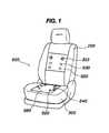
- FIG. 1is a diagram showing the arrangement of sensors of an exemplary system for observing the heart rate of a passenger according to the present invention.
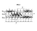
- FIG. 2is a graph showing a process for evaluating and selecting heart rates in the system for observing the heart rate of a passenger shown in FIG. 1 .
- FIG. 3is a flowchart showing an exemplary method of observing the heart rate of a passenger according to the present invention.
- FIG. 4is a graph showing the waveform of a theoretical ECG.
- FIG. 5is a graph showing the waveform of a theoretical BCG.
- FIG. 1is a diagram showing the arrangement of sensors of a system for observing the heart rate of a passenger according to various embodiments of the present invention
- FIG. 3is a flowchart showing a method of observing the heart rate of a passenger according to various embodiments of the present invention.
- the system for observing the heart rate of a passengerincludes a plurality of different types of heart rate sensors 500 provided on a seat cushion 300 or a seat back 100 ; and a control unit for collecting waveforms of the heart rate sensors 500 for respective sensor types, computes the accuracies of the waveforms for respective sensor types at each unit time, selects a waveform having the highest accuracy at each unit time, and then calculates a heart rate based on the selected waveform.
- the heart rate sensorsare implemented as a combination of a plurality of sensors capable of measuring the heart rate using various methods, so that the heart rate sensors can be selectively applied to optimal locations on the seat back or the seat cushion of a seat.
- Such different types of heart rate sensors 500can individually measure signals related to the heart rate using mechanical, electrical, or optical methods.
- Representative embodiments of the methodsmay include the electrocardiogram (ECG), ballistocardiogram (BCG), phonocardiogram (PCG), and photoplethysmogram (PPG).
- ECGelectrocardiogram
- BCGballistocardiogram
- PCGphonocardiogram
- PPGphotoplethysmogram
- ECGis a method of measuring the voltage generated when the heart muscle is activated at two extracorporeal points.
- a PPGwhich is a method of measuring variations in the amount of blood at an end-organ using variations in the amount of received light.
- BCGwhich is a method of measuring the reaction to the ejection of blood when the heart ejects the blood
- PCGa method of measuring sounds, caused by vibrations created when the valves of the heart open and close, at extracorporeal locations.
- Such signalsare synchronized with one another according to a specific time difference.
- the degree of the time differenceis influenced by various physiological variables, such as the elasticity of a blood vessel or a blood pressure.
- the ECGcan be measured in a non-restrained measurement manner using a circuit that is capable of measuring the potential difference between two positions of the body and capacitive electrodes that are embedded in the seat.
- the BCGcan be measured by disposing sensors, capable of measuring pressure or weight, between a human being and a seat frame.
- the PCGcan be measured by bringing a stethoscope into close contact with the surface of the skin around the heart and by recording sounds using the stethoscope.
- the PPGcan be measured in such a way as to emit light to a blood vessel around the skin using a sensor implemented as a pair of a light emitting unit and a light receiving unit, and measure the amount of light reflected by (or passed through) the blood vessel.
- a scheme for overcoming such disadvantagesis to use a combination of different types of heart rate sensors.
- the reason for thisis that their sensitivities to respective environment variables differ depending on the type of sensor.
- FIG. 1illustrates the locations at which individual sensors are installed, which will be described in detail for respective sensors.
- the control unitcollects the waveforms of the heart rate sensors 500 for respective sensor types, computes the accuracies of the waveforms for respective sensor types at each unit time, selects a waveform having the highest accuracy from among the waveforms at each unit time, and then calculates the heart rate based on the selected waveform.
- the heart rate sensors 500are implemented as a plurality of sensors for each type.
- the control unitcan select representative waveforms for respective types of the heart rate sensors, compute the accuracies of the selected waveforms at each unit time, select a waveform having the highest accuracy at each unit time, and calculate a heart rate based on the selected waveform.
- the control unitevaluates waveforms for each type of sensor. Criteria for the evaluation may include items, such as whether each signal has been saturated, whether a base line is wandering, the degree of distortion of waveforms, the comparison of energy in a frequency domain, and signal energy in a time domain.
- evaluationis performed at each unit time, such as t1, t2, and t3.
- t1it is determined that the waveform of a PPG has the highest accuracy
- t2it is determined that the waveform of a BCG has the highest accuracy
- t3it is determined that the waveform of an ECG has the highest accuracy
- t4it is determined that the waveform of a PPG has the highest accuracy
- the heart ratesare respectively calculated using the different waveforms at respective unit times. Further, since this calculation procedure uses the results of calculation while shifting waveforms, more accurate results can be obtained if time differences that may occur at the moment at which each waveform shifts (a shifting time point) are corrected.
- the heart rate sensors 500may include ECG sensors 510 .
- the ECG sensors 510may be provided such that respective pairs 510 and 520 of ECG sensors are provided on the seat back 100 and the seat cushion 300 , and the control unit configures a plurality of ECG measurement circuit leads by combining the plurality of ECG sensors 510 , thus deriving a plurality of waveforms related to the ECG.
- control unitmay measure the magnitudes of the R-peak and the P-peak of each waveform related to the ECG, and select a waveform, in which the magnitude of an R-peak is five times or more as large as that of a P-peak, as the representative ECG waveform.
- control unitmay measure the R-peak and the T-peak of each waveform related to the ECG and select a waveform, in which the magnitude of an R-peak is three times or more as large as that of a T-peak, as the representative ECG waveform.
- FIG. 4is a graph showing the waveform of a theoretical ECG. That is, the ECG sensors must be implemented as at least a pair (two sensors) so as to measure a single signal, and at least two pairs of sensors are located in a back contact portion and a hip contact portion of the seat, respectively. Accordingly, when the contact position has changed due to a variation in the posture of the passenger, combinations of different sensors can be selected.
- nC2It is possible to implement nC2 combinations depending on the combination of selecting two sensors from among n sensors, and configure individual leads of the ECG. Since the strength of the contact between the sensors located in individual portions of the seat and the surface of the body varies according to the posture of an examinee (passenger), the state of contact of the individual sensors is determined in real time, and leads from which signals are expected to be desirably output are selected.
- the magnitudes of the R-peak, P-peak, and T-peak of each signalare measured.
- the ratios of the magnitudes of the peaksare calculated, and signals suitably satisfying the ratios of R-peak and P-peak of 5:1 or more and the ratios of R-peak and T-peak of 3:1 or more are selected and defined as high-quality signals, and the optimal ECG signal is selected from among the defined ECG signals.
- an electrocardiogramthat is, the ECG
- ECGis a graph of active current obtained by measuring at two extracorporeal points the current that flows when a heart muscle is activated.
- the ECGis widely applied to the fields of diagnosis of various types of arrhythmia or electrolytic disorders, or the examination and verification of the existence of abnormalities of the heart while performing an operation, as well as coronary diseases such as the stricture of the heart or myocardial infarction, and is very important to the diagnostics of cardiac diseases.
- Heart Rate Variabilityis an index required to measure the time intervals between the R-peaks of the ECG and check physiological conditions. For a normal person, a variation in the R-R peak interval occurs because the autonomic nervous system antagonizes the part that generates the heart rhythm. Therefore, when the variation in the R-R peak interval is analyzed, the activity of the sympathetic/parasympathetic nervous systems constituting the autonomic nervous system can be detected.
- the activity of the sympathetic/parasympathetic nervous systemsis well known as one of the sensitive variables that desirably reflect the stressed condition of the body.
- FIG. 5is a graph showing the waveform of a theoretical BCG.
- the heart rate sensors 500may include BCG sensors 550 .
- the BCG 550may be individually provided on the seat back 100 and on the seat cushion 300 , as indicated by reference numerals 550 and 560 .
- a plurality of BCG sensors 550are provided, and the control unit can derive a plurality of waveforms related to the BCG for respective BCG sensors 550 , compare the magnitude of an I-J signal with the magnitude of a noise signal for each waveform, and select a waveform, in which the magnitude of an I-J signal is seven times or more as large as that of a noise signal, as the representative BCG waveform.
- sensors implemented as piezoelectric elementsare disposed in a hip contact portion because the principle of the BCG is based on the repulsive power with which the blood flow is ejected from the heart.
- the output waveform of the BCGmay vary according to the state of contact between the examinee and the surfaces of the sensors because the angles between a blood vessel and the BCG sensors differ according to the posture of a user (the examinee).
- Four (2*2 array) or more BCG sensorsare disposed in the hip contact portion, so that signals can be obtained in accordance with variations in the posture of the examinee, differences in the location of contact attributable to the center of gravity of the body of the examinee, etc.
- each BCG signalthe magnitude of an I-J signal is compared with a noise level, so that BCG signals in which the magnitude of an I-J signal is seven times or more as large as a noise level are defined as high-quality signals, and an optimal BCG signal is selected from among the high-quality signals.
- the BCGrefers to a ballistocardiogram that is a method of, when the heart ejects blood, measuring a reaction to the ejection, and then estimating the state of the heart.
- This BCGis obtained by directly measuring a fine variation in acceleration or a variation in the weight of the body, caused by the reaction to the ejection of a blood flow, and is intended to determine the magnitudes, time intervals, or gradients of the signals.
- the magnitude of the I-J signalis used as the most principal target of analysis.
- Idenotes a signal output when the heart ejects blood through the main artery
- Jdenotes a signal output when blood moves down to the lower part of the body, wherein the contractile force of the left ventricle can be estimated using the magnitude of the I-J signal.
- the heart rate sensors 500may include PCG sensors 530 .
- the PCG sensors 530are provided on the seat back 100 .
- a plurality of PCG sensors 530may be provided in series on the seat back 100 in a vertical direction.
- the plurality of PCG sensors 530are provided, and the control unit can derive a plurality of waveforms related to the PCG for respective PCG sensors 530 , compare the maximum amplitude of a first cardiac sound with the magnitude of a noise signal for each waveform, and select a waveform, in which the maximum amplitude of a first cardiac sound is five times or more as large as that of the noise signal, as the representative PCG waveform.
- a plurality of PCG sensors 530are provided, and the control unit can derive a plurality of waveforms related to the PCG for respective PCG sensors 530 , compare the maximum amplitude of a second cardiac sound with the magnitude of a noise signal for each waveform, and select a waveform, in which the magnitude of a second cardiac sound is three times or more as large as that of a noise signal, as the representative PCG waveform.
- the PCG sensorsare located on the backrest of the seat so as to record the sounds that occur when the valves of the heart open and close, and are each composed of a high-sensitive microphone and a sound collecting structure. Since the body shape of each person differs, a portion in which the seat back and the heart correspond to each other will differ, so that the PCG sensors are located on the backrest of the seat in the vertical direction.
- the PCG signalssatisfy conditions in which the maximum amplitude of a first cardiac sound and the maximum amplitude of a second cardiac sound are respectively five times or more and three times or more as large as the noise level, the PCG signals are defined as high-quality signals, and an optimal PCG signal is selected from among the high-quality signals.
- the PCGdenotes a phonocardiogram, which is used to detect the period of the heart rate or analyze cardiac diseases by extracorporeally measuring sounds caused by vibrations occurring when the valves of the heart open and close. While the heart squeezes and pumps blood throughout the entire body when the mitral valve closes and the aortic valve opens, a first cardiac sound is generated. While new blood is coming into the left ventricle when the arterial blood flows out of the heart and then the mitral valve opens and the aortic valve closes, a second cardiac sound is generated.
- the heart rate sensors 500may include PPG sensors 540 .
- the PPG sensors 540may be arranged at locations of the seat cushion 300 , which come into contact with the thighs of the passenger.
- a plurality of PPG sensors 540can be provided, and the control unit can derive a plurality of waveforms related to the PPG for the respective PPG sensors 540 , and select a waveform, in which a largest number of frequency components ranging from 0.5 to 2 Hz are present, from among the plurality of waveforms as the representative PPG waveform.
- the PPG sensorsare implemented using high-efficiency Light Emitting Diodes (LEDs) having near-infrared rays and red wavelength bands so as to take the PPG measurements while passing through the seat and clothes of the passenger, and are vertically configured such that they come into contact with the backs of the thighs of the passenger where there are relatively thick blood vessels.
- the PPG signalsare subjected to Fast Fourier Transform (FFT), so that channels having a larger number of frequency components having a period of 0.5 to 2 Hz are defined as candidates for high-quality signals and then an optimal signal is selected after template matching has been performed using a basic PPG waveform.
- FFTFast Fourier Transform
- the PPGis a method of measuring the waveform of blood using light because when the blood is periodically pumped out by the heart, the blood flows through blood vessels in the shape of a uniform wave. In this case, if the waveform is measured using two wavelength bands and measured values are compared, oxygen saturation in the blood can be measured.
- FIG. 3is a flowchart showing a method of observing the heart rate of a passenger according to various embodiments of the present invention.
- the method of observing the heart rate of a passenger according to the present inventionincludes the collection step S 100 of collecting waveforms from a plurality of different types of heart rate sensors provided on a seat cushion or a seat back, for respective sensor types; the computing step S 200 of computing accuracies of the waveforms for respective sensor types at each unit time; the selection step S 300 of selecting a waveform having the highest accuracy at each unit time; and the calculation step S 400 of calculating a heart rate based on the selected waveform.
- the methodmay further include the step S 500 of determining the physical condition or the like of the passenger using the calculated heart rate, and the step S 600 of, after step S 500 , providing a service such as a warning using a voice, a motion or a touch, or a call to a hospital or a simple diagnosis.
- a servicesuch as a warning using a voice, a motion or a touch, or a call to a hospital or a simple diagnosis.
- the system and method for observing the heart rate of a passenger having the above configurationare advantageous in that for a plurality of different types of sensors and even for the same type of sensor, the most optimal signal among a plurality of signals is periodically evaluated and selected, thus reliably obtaining a relatively accurate heart rate.
Landscapes
- Health & Medical Sciences (AREA)
- Life Sciences & Earth Sciences (AREA)
- Engineering & Computer Science (AREA)
- Public Health (AREA)
- Biomedical Technology (AREA)
- Medical Informatics (AREA)
- Cardiology (AREA)
- General Health & Medical Sciences (AREA)
- Pathology (AREA)
- Heart & Thoracic Surgery (AREA)
- Physics & Mathematics (AREA)
- Biophysics (AREA)
- Molecular Biology (AREA)
- Surgery (AREA)
- Animal Behavior & Ethology (AREA)
- Veterinary Medicine (AREA)
- Physiology (AREA)
- Vascular Medicine (AREA)
- Psychiatry (AREA)
- Databases & Information Systems (AREA)
- Child & Adolescent Psychology (AREA)
- Developmental Disabilities (AREA)
- Educational Technology (AREA)
- Ophthalmology & Optometry (AREA)
- Psychology (AREA)
- Social Psychology (AREA)
- Hospice & Palliative Care (AREA)
- Data Mining & Analysis (AREA)
- Hematology (AREA)
- Epidemiology (AREA)
- Primary Health Care (AREA)
- Measuring Pulse, Heart Rate, Blood Pressure Or Blood Flow (AREA)
- Measurement And Recording Of Electrical Phenomena And Electrical Characteristics Of The Living Body (AREA)
Abstract
Description
| TABLE 1 | |||
| Humidity | Clothing thickness | Sitting posture | |
| ECG | Very sensitive | Slightly sensitive | Insensitive |
| PCG | Insensitive | Very sensitive | Slightly sensitive |
| BCG | Insensitive | Insensitive | Sensitive |
| PPG | Insensitive | Slightly sensitive | Insensitive |
| TABLE 2 | ||
| Cushion | Seat back | |
| ECG | Contact surface with | Contact surface with left and |
| left and right thighs | right lumbar vertebrae | |
| PCG | N/A | Center portions of thoracic |
| curves | ||
| BCG | Contact surface with hips | Left and right regions of back |
| PPG | Contact surface with thighs | N/A |
Claims (10)
Applications Claiming Priority (2)
| Application Number | Priority Date | Filing Date | Title |
|---|---|---|---|
| KR10-2012-0085070 | 2012-08-03 | ||
| KR1020120085070AKR101316497B1 (en) | 2012-08-03 | 2012-08-03 | System and method for observing heart rate of passenger |
Publications (2)
| Publication Number | Publication Date |
|---|---|
| US20140039330A1 US20140039330A1 (en) | 2014-02-06 |
| US8706204B2true US8706204B2 (en) | 2014-04-22 |
Family
ID=49638059
Family Applications (1)
| Application Number | Title | Priority Date | Filing Date |
|---|---|---|---|
| US13/682,468ActiveUS8706204B2 (en) | 2012-08-03 | 2012-11-20 | System and method for observing heart rate of passenger |
Country Status (4)
| Country | Link |
|---|---|
| US (1) | US8706204B2 (en) |
| KR (1) | KR101316497B1 (en) |
| CN (1) | CN103565429B (en) |
| DE (1) | DE102012111859A1 (en) |
Cited By (31)
| Publication number | Priority date | Publication date | Assignee | Title |
|---|---|---|---|---|
| US20140303899A1 (en)* | 2013-04-06 | 2014-10-09 | Honda Motor Co., Ltd. | System and method for biometric identification in a vehicle |
| US20150297125A1 (en)* | 2012-11-27 | 2015-10-22 | Faurecia Automotive Seating, Llc | Oximetry sensor assembly and methodology for sensing blood oxygen concentration |
| US20150313475A1 (en)* | 2012-11-27 | 2015-11-05 | Faurecia Automotive Seating, Llc | Vehicle seat with integrated sensors |
| US9440646B2 (en) | 2011-02-18 | 2016-09-13 | Honda Motor Co., Ltd. | System and method for responding to driver behavior |
| US9475502B2 (en) | 2011-02-18 | 2016-10-25 | Honda Motor Co., Ltd. | Coordinated vehicle response system and method for driver behavior |
| US9751534B2 (en) | 2013-03-15 | 2017-09-05 | Honda Motor Co., Ltd. | System and method for responding to driver state |
| WO2017152098A1 (en)* | 2016-03-03 | 2017-09-08 | Board Of Trustees Of Michigan State University | Method and apparatus for cuff-less blood pressure measurement |
| US10034631B1 (en) | 2017-05-19 | 2018-07-31 | Lear Corporation | Vehicle seating system with seat occupant vital sign monitoring |
| US10153796B2 (en) | 2013-04-06 | 2018-12-11 | Honda Motor Co., Ltd. | System and method for capturing and decontaminating photoplethysmopgraphy (PPG) signals in a vehicle |
| US10213162B2 (en) | 2013-04-06 | 2019-02-26 | Honda Motor Co., Ltd. | System and method for capturing and decontaminating photoplethysmopgraphy (PPG) signals in a vehicle |
| US10363846B2 (en) | 2017-05-30 | 2019-07-30 | Lear Corporation | Vehicle seating system having seat with individually controllable electromagnetic coils |
| US10398324B2 (en) | 2016-03-03 | 2019-09-03 | Board Of Trustees Of Michigan State University | Method and apparatus for cuff-less blood pressure measurement in a mobile device |
| US10499856B2 (en) | 2013-04-06 | 2019-12-10 | Honda Motor Co., Ltd. | System and method for biological signal processing with highly auto-correlated carrier sequences |
| US10537288B2 (en) | 2013-04-06 | 2020-01-21 | Honda Motor Co., Ltd. | System and method for biological signal processing with highly auto-correlated carrier sequences |
| US10542961B2 (en) | 2015-06-15 | 2020-01-28 | The Research Foundation For The State University Of New York | System and method for infrasonic cardiac monitoring |
| US10556532B2 (en) | 2017-05-15 | 2020-02-11 | Lear Corporation | Seating system having seat with individually controllable thermal units |
| US10576988B2 (en) | 2017-08-02 | 2020-03-03 | Electronics And Telecommunications Research Institute | Biosignal detecting device and biosignal detecting system including the same |
| US10806350B2 (en) | 2018-06-27 | 2020-10-20 | Faurecia Automotive Seating, Llc | Sensor system for occupant support |
| US10939840B2 (en) | 2014-09-23 | 2021-03-09 | Rr Sequences Inc. | Contactless electric cardiogram system |
| US11052223B2 (en) | 2017-12-21 | 2021-07-06 | Lear Corporation | Seat assembly and method |
| US11059490B1 (en) | 2020-03-17 | 2021-07-13 | Lear Corporation | Seat system |
| US11173818B1 (en) | 2020-05-13 | 2021-11-16 | Lear Corporation | Seat assembly |
| US11292371B2 (en) | 2020-05-13 | 2022-04-05 | Lear Corporation | Seat assembly |
| US11524691B2 (en) | 2019-07-29 | 2022-12-13 | Lear Corporation | System and method for controlling an interior environmental condition in a vehicle |
| US11590873B2 (en) | 2020-05-13 | 2023-02-28 | Lear Corporation | Seat assembly |
| DE102021209759A1 (en) | 2021-09-06 | 2023-03-09 | Robert Bosch Gesellschaft mit beschränkter Haftung | Method and device for determining the vital functions of a vehicle occupant |
| US11634055B2 (en) | 2020-05-13 | 2023-04-25 | Lear Corporation | Seat assembly |
| US11679706B2 (en) | 2020-12-02 | 2023-06-20 | Lear Corporation | Seat assembly |
| US20240001842A1 (en)* | 2022-06-29 | 2024-01-04 | Robert Bosch Gmbh | System and method of capturing physiological anomalies utilizing a vehicle seat |
| DE102022209446A1 (en) | 2022-09-09 | 2024-03-14 | Robert Bosch Gesellschaft mit beschränkter Haftung | Method and device for determining cardiogram signals from one or more people |
| US12059980B2 (en) | 2019-06-21 | 2024-08-13 | Lear Corporation | Seat system and method of control |
Families Citing this family (52)
| Publication number | Priority date | Publication date | Assignee | Title |
|---|---|---|---|---|
| CN104756148B (en)* | 2012-09-25 | 2018-12-14 | 斯库特网络公司 | Systems and methods for regulating vehicle access |
| WO2014157896A1 (en) | 2013-03-24 | 2014-10-02 | 서울대학교산학협력단 | Film-type device for measuring biomedical signal, and blood pressure measurement device, cardiopulmonary endurance estimation device, and individual certification device using same |
| KR101593684B1 (en)* | 2014-03-24 | 2016-02-12 | 서울대학교 산학협력단 | Personal authentication device and method using film-type bio-signal measurement device |
| KR101576665B1 (en)* | 2014-01-23 | 2015-12-21 | 서울대학교 산학협력단 | Blood pressure measurement device and method using film-type bio-signal measurement device |
| DE102013216604A1 (en)* | 2013-08-22 | 2015-02-26 | Ford Global Technologies, Llc | Sensor for contactless electrocardiographic measurement, sensor array and seat or couch |
| KR101509959B1 (en) | 2013-11-01 | 2015-04-08 | 현대자동차주식회사 | Ballistocardiogram analysis system and method for vehicle |
| CN106068097B (en)* | 2014-02-20 | 2020-09-29 | 佛吉亚汽车座椅有限责任公司 | Vehicle seat with integrated sensor |
| WO2015153569A1 (en)* | 2014-03-31 | 2015-10-08 | The Regents Of The University Of Michigan | Miniature piezoelectric cardiovascular monitoring system |
| CN104224162B (en)* | 2014-05-26 | 2016-07-13 | 东北大学 | A driver's ECG monitoring system and method based on Android mobile phone and 3D electrodes |
| US9717427B2 (en)* | 2014-05-30 | 2017-08-01 | Microsoft Technology Licensing, Llc | Motion based estimation of biometric signals |
| CN104146702B (en)* | 2014-08-14 | 2016-03-16 | 张新房 | New bio electric induction health risk assessment system |
| CN104323765A (en)* | 2014-11-15 | 2015-02-04 | 同心医联科技(北京)有限公司 | Microscale pressure sensing-based heart health monitoring device |
| CN204515353U (en)* | 2015-03-31 | 2015-07-29 | 深圳市长桑技术有限公司 | A kind of intelligent watch |
| US10011176B2 (en) | 2015-01-20 | 2018-07-03 | Ford Global Technologies, Llc | Method and device for recognising the condition of vehicle occupants |
| US10449874B2 (en)* | 2015-03-27 | 2019-10-22 | Ts Tech Co., Ltd. | Seat with detector |
| KR101619702B1 (en) | 2015-04-09 | 2016-05-10 | 현대자동차주식회사 | Apparatus for adjusting position of bio-signal measuring sensor |
| US10292658B2 (en)* | 2015-06-23 | 2019-05-21 | Rochester Institute Of Technology | Apparatus, system and method for medical analyses of seated individual |
| US10046671B2 (en) | 2015-08-14 | 2018-08-14 | Faurecia Automotive Seating, Llc | Occupant-recognition system for vehicle seat |
| US10160544B2 (en)* | 2015-09-09 | 2018-12-25 | Airbus Group India Private Limited | Aircraft occupant health, safety, and comfort management |
| US10176694B2 (en)* | 2015-09-09 | 2019-01-08 | Airbus Group India Private Limited | Aircraft occupant seat for aircraft occupant health, safety, and comfort management |
| KR101764174B1 (en) | 2015-10-14 | 2017-08-02 | 전자부품연구원 | Method of monitoring user's status, monitoring system performing the same |
| CN106585444B (en)* | 2015-10-14 | 2019-03-15 | 江苏爱思普医疗科技有限公司 | A kind of anti-tired automobile cushion and its anti-fatigue method |
| EP3387988B1 (en)* | 2015-12-12 | 2024-02-28 | Delta Kogyo Co., Ltd. | Biological state estimation device, biological state estimation method, computer program, and recording medium |
| CN108430321B (en)* | 2015-12-23 | 2023-01-10 | 皇家飞利浦有限公司 | Devices, systems and methods for determining vital signs of a human |
| US9848035B2 (en)* | 2015-12-24 | 2017-12-19 | Intel Corporation | Measurements exchange network, such as for internet-of-things (IoT) devices |
| WO2017135263A1 (en)* | 2016-02-05 | 2017-08-10 | テイ・エス テック株式会社 | Bioinformation measurement device |
| JP6475680B2 (en)* | 2016-02-05 | 2019-02-27 | テイ・エス テック株式会社 | Biological information measuring device |
| US10182789B2 (en)* | 2016-03-03 | 2019-01-22 | David R. Hall | Toilet with stethoscope |
| CN105877700B (en)* | 2016-03-28 | 2020-02-21 | 联想(北京)有限公司 | Vital sign detection method and vital sign detection device |
| US10918337B2 (en) | 2016-06-03 | 2021-02-16 | Faurecia Automotive Seating, Llc | Vehicle seat with integrated sensors |
| US11197637B2 (en)* | 2016-06-20 | 2021-12-14 | Faurecia Automotive Seating, Llc | Control system for a vehicle seat |
| US10426411B2 (en)* | 2016-06-29 | 2019-10-01 | Samsung Electronics Co., Ltd. | System and method for providing a real-time signal segmentation and fiducial points alignment framework |
| US10730524B2 (en)* | 2016-09-07 | 2020-08-04 | Faurecia Automotive Seating, Llc | Vehicle seat |
| JP7093918B2 (en)* | 2017-08-02 | 2022-07-01 | カレシス エルティーディー | Non-contact detection and monitoring system for vital signs of car occupants |
| US11083379B2 (en) | 2017-08-02 | 2021-08-10 | Faurecia Automotive Seating, Llc | Health-monitoring seat cover |
| US10499827B2 (en)* | 2017-09-19 | 2019-12-10 | Honeywell International Inc. | System and method for interpretation of signal-to-noise ratios detected in an array of electrodes sensors in terms of physical and cognitive state |
| KR20190061726A (en)* | 2017-11-28 | 2019-06-05 | 현대자동차주식회사 | System and method for adjusting drivingcontrol of vehicle |
| US10709386B2 (en)* | 2017-12-12 | 2020-07-14 | Lear Corporation | Electrocardiogram waveform identification and diagnostics via electrophysiological sensor system fusion |
| US20190184853A1 (en)* | 2017-12-19 | 2019-06-20 | GM Global Technology Operations LLC | Occupant sensing system for a vehicle |
| WO2019204144A1 (en) | 2018-04-16 | 2019-10-24 | Bird Rides, Inc. | On-demand rental of electric vehicles |
| DE102019203979A1 (en) | 2019-03-22 | 2020-09-24 | Greiner Aerospace Gmbh | Seat cushion for an aircraft seat with integrated sensor electronics |
| US10949659B2 (en)* | 2019-04-16 | 2021-03-16 | GM Global Technology Operations LLC | Vehicle occupant detection |
| IT201900021993A1 (en)* | 2019-11-22 | 2021-05-22 | Martur Italy Srl | Intelligent vehicle seat cover and vehicle seat including such smart cover |
| CN110916639B (en)* | 2019-12-23 | 2022-09-02 | 深圳市圆周率智能信息科技有限公司 | Method, system, wearable device and computer-readable storage medium for acquiring exercise heart rate recovery rate |
| KR102318752B1 (en)* | 2020-05-29 | 2021-10-28 | 주식회사 엠마헬스케어 | Smart chair capable of detecting noninvasive biosignal and processing data in the sitting state |
| US11786161B2 (en)* | 2020-10-06 | 2023-10-17 | Samer Nasry | Garment medical examination system |
| EP4014850B1 (en)* | 2020-12-16 | 2024-07-24 | Polar Electro Oy | Method for measuring pre-ejection period |
| KR102520875B1 (en)* | 2021-03-31 | 2023-04-12 | 주식회사 엠마헬스케어 | Recliner having health care performance |
| EP4319630A1 (en) | 2021-04-09 | 2024-02-14 | Casana Care, Inc. | Systems, devices, and methods for monitoring loads and forces on a seat |
| AU2022271784A1 (en) | 2021-05-11 | 2023-10-05 | Casana Care, Inc. | Systems, devices, and methods for measuring loads and forces of a seated subject using scale devices |
| EP4340712A1 (en) | 2021-05-17 | 2024-03-27 | Casana Care, Inc. | Systems, devices, and methods for measuring body temperature of a subject using characterization of feces and/or urine |
| CN116691472A (en)* | 2023-06-27 | 2023-09-05 | 江苏开沃汽车有限公司 | Vehicle Seats and Vehicles |
Citations (4)
| Publication number | Priority date | Publication date | Assignee | Title |
|---|---|---|---|---|
| US20060283652A1 (en)* | 2005-06-15 | 2006-12-21 | Denso Corporation | Biosignal detection device |
| KR100736721B1 (en) | 2004-08-31 | 2007-07-09 | 재단법인서울대학교산학협력재단 | Electric non-contact apparatus and method for taking electrocardiograms |
| US7379770B2 (en)* | 2003-05-13 | 2008-05-27 | Dayton Technologies Limited | Devices and methods for heart rate measurement and wrist-watch incorporating same |
| JP2011024902A (en) | 2009-07-28 | 2011-02-10 | Toyota Motor Corp | Electrocardiographic device for vehicle |
Family Cites Families (10)
| Publication number | Priority date | Publication date | Assignee | Title |
|---|---|---|---|---|
| WO2004110241A2 (en)* | 2003-06-16 | 2004-12-23 | Century Ocean Corporation Limited | Devices and methods for heart-rate measurement and wrist-watch incorporating same |
| CA2477615A1 (en) | 2004-07-15 | 2006-01-15 | Quantum Applied Science And Research, Inc. | Unobtrusive measurement system for bioelectric signals |
| JP2007167545A (en)* | 2005-12-26 | 2007-07-05 | Honda Motor Co Ltd | Biological condition detection device |
| JP4864497B2 (en) | 2006-03-14 | 2012-02-01 | パナソニック株式会社 | Heart rate information detector |
| JP4743534B2 (en) | 2006-09-28 | 2011-08-10 | アイシン精機株式会社 | Heart rate detector |
| CN101234016A (en)* | 2007-01-29 | 2008-08-06 | 香港中文大学 | Physiological parameter measuring device |
| JP2010063682A (en)* | 2008-09-11 | 2010-03-25 | Aisin Seiki Co Ltd | Driver monitoring apparatus |
| JP5416218B2 (en)* | 2008-12-12 | 2014-02-12 | コーニンクレッカ フィリップス エヌ ヴェ | Analytical method and apparatus for ballisto cardiogram signal |
| JP2010142456A (en)* | 2008-12-19 | 2010-07-01 | Panasonic Corp | Heartbeat detecting apparatus |
| KR101249898B1 (en) | 2011-01-21 | 2013-04-09 | 엘지전자 주식회사 | Heat pump |
- 2012
- 2012-08-03KRKR1020120085070Apatent/KR101316497B1/enactiveActive
- 2012-11-20USUS13/682,468patent/US8706204B2/enactiveActive
- 2012-12-06DEDE102012111859.0Apatent/DE102012111859A1/ennot_activeWithdrawn
- 2012-12-11CNCN201210532301.XApatent/CN103565429B/enactiveActive
Patent Citations (5)
| Publication number | Priority date | Publication date | Assignee | Title |
|---|---|---|---|---|
| US7379770B2 (en)* | 2003-05-13 | 2008-05-27 | Dayton Technologies Limited | Devices and methods for heart rate measurement and wrist-watch incorporating same |
| KR100736721B1 (en) | 2004-08-31 | 2007-07-09 | 재단법인서울대학교산학협력재단 | Electric non-contact apparatus and method for taking electrocardiograms |
| US7684854B2 (en)* | 2004-08-31 | 2010-03-23 | Seoul National University Industry Foundation | Apparatus and method for measuring electric non-contact electrocardiogram in everyday life |
| US20060283652A1 (en)* | 2005-06-15 | 2006-12-21 | Denso Corporation | Biosignal detection device |
| JP2011024902A (en) | 2009-07-28 | 2011-02-10 | Toyota Motor Corp | Electrocardiographic device for vehicle |
Cited By (55)
| Publication number | Priority date | Publication date | Assignee | Title |
|---|---|---|---|---|
| US9855945B2 (en) | 2011-02-18 | 2018-01-02 | Honda Motor Co., Ltd. | System and method for responding to driver behavior |
| US11377094B2 (en) | 2011-02-18 | 2022-07-05 | Honda Motor Co., Ltd. | System and method for responding to driver behavior |
| US9440646B2 (en) | 2011-02-18 | 2016-09-13 | Honda Motor Co., Ltd. | System and method for responding to driver behavior |
| US9475502B2 (en) | 2011-02-18 | 2016-10-25 | Honda Motor Co., Ltd. | Coordinated vehicle response system and method for driver behavior |
| US9505402B2 (en) | 2011-02-18 | 2016-11-29 | Honda Motor Co., Ltd. | System and method for responding to driver behavior |
| US10875536B2 (en) | 2011-02-18 | 2020-12-29 | Honda Motor Co., Ltd. | Coordinated vehicle response system and method for driver behavior |
| US9873437B2 (en) | 2011-02-18 | 2018-01-23 | Honda Motor Co., Ltd. | Coordinated vehicle response system and method for driver behavior |
| US20150297125A1 (en)* | 2012-11-27 | 2015-10-22 | Faurecia Automotive Seating, Llc | Oximetry sensor assembly and methodology for sensing blood oxygen concentration |
| US20150313475A1 (en)* | 2012-11-27 | 2015-11-05 | Faurecia Automotive Seating, Llc | Vehicle seat with integrated sensors |
| US11383721B2 (en) | 2013-03-15 | 2022-07-12 | Honda Motor Co., Ltd. | System and method for responding to driver state |
| US9751534B2 (en) | 2013-03-15 | 2017-09-05 | Honda Motor Co., Ltd. | System and method for responding to driver state |
| US10759438B2 (en) | 2013-03-15 | 2020-09-01 | Honda Motor Co., Ltd. | System and method for responding to driver state |
| US10759437B2 (en) | 2013-03-15 | 2020-09-01 | Honda Motor Co., Ltd. | System and method for responding to driver state |
| US10752252B2 (en) | 2013-03-15 | 2020-08-25 | Honda Motor Co., Ltd. | System and method for responding to driver state |
| US10759436B2 (en) | 2013-03-15 | 2020-09-01 | Honda Motor Co., Ltd. | System and method for responding to driver state |
| US10246098B2 (en) | 2013-03-15 | 2019-04-02 | Honda Motor Co., Ltd. | System and method for responding to driver state |
| US10308258B2 (en) | 2013-03-15 | 2019-06-04 | Honda Motor Co., Ltd. | System and method for responding to driver state |
| US10780891B2 (en) | 2013-03-15 | 2020-09-22 | Honda Motor Co., Ltd. | System and method for responding to driver state |
| US10213162B2 (en) | 2013-04-06 | 2019-02-26 | Honda Motor Co., Ltd. | System and method for capturing and decontaminating photoplethysmopgraphy (PPG) signals in a vehicle |
| US10499856B2 (en) | 2013-04-06 | 2019-12-10 | Honda Motor Co., Ltd. | System and method for biological signal processing with highly auto-correlated carrier sequences |
| US10537288B2 (en) | 2013-04-06 | 2020-01-21 | Honda Motor Co., Ltd. | System and method for biological signal processing with highly auto-correlated carrier sequences |
| US10945672B2 (en) | 2013-04-06 | 2021-03-16 | Honda Motor Co., Ltd. | System and method for capturing and decontaminating photoplethysmopgraphy (PPG) signals in a vehicle |
| US9272689B2 (en)* | 2013-04-06 | 2016-03-01 | Honda Motor Co., Ltd. | System and method for biometric identification in a vehicle |
| US10153796B2 (en) | 2013-04-06 | 2018-12-11 | Honda Motor Co., Ltd. | System and method for capturing and decontaminating photoplethysmopgraphy (PPG) signals in a vehicle |
| US20140303899A1 (en)* | 2013-04-06 | 2014-10-09 | Honda Motor Co., Ltd. | System and method for biometric identification in a vehicle |
| US10939840B2 (en) | 2014-09-23 | 2021-03-09 | Rr Sequences Inc. | Contactless electric cardiogram system |
| US11064927B2 (en) | 2014-09-23 | 2021-07-20 | Rr Sequences Inc. | Contactless electric cardiogram system |
| US10542961B2 (en) | 2015-06-15 | 2020-01-28 | The Research Foundation For The State University Of New York | System and method for infrasonic cardiac monitoring |
| US11478215B2 (en) | 2015-06-15 | 2022-10-25 | The Research Foundation for the State University o | System and method for infrasonic cardiac monitoring |
| US11179047B2 (en) | 2016-03-03 | 2021-11-23 | Board Of Trustees Of Michigan State University | Method and apparatus for cuff-less blood pressure measurement in a mobile device |
| WO2017152098A1 (en)* | 2016-03-03 | 2017-09-08 | Board Of Trustees Of Michigan State University | Method and apparatus for cuff-less blood pressure measurement |
| US10398324B2 (en) | 2016-03-03 | 2019-09-03 | Board Of Trustees Of Michigan State University | Method and apparatus for cuff-less blood pressure measurement in a mobile device |
| US11684274B2 (en) | 2016-03-03 | 2023-06-27 | Board Of Trustees Of Michigan State University | Method and apparatus for cuff-less blood pressure measurement in a mobile device |
| US10556532B2 (en) | 2017-05-15 | 2020-02-11 | Lear Corporation | Seating system having seat with individually controllable thermal units |
| US10213147B2 (en) | 2017-05-19 | 2019-02-26 | Lear Corporation | Method and systems for detecting from biometrics that person sitting in seat of vehicle requires medical attention and for providing medical attention to the person |
| US10034631B1 (en) | 2017-05-19 | 2018-07-31 | Lear Corporation | Vehicle seating system with seat occupant vital sign monitoring |
| US10363846B2 (en) | 2017-05-30 | 2019-07-30 | Lear Corporation | Vehicle seating system having seat with individually controllable electromagnetic coils |
| US10576988B2 (en) | 2017-08-02 | 2020-03-03 | Electronics And Telecommunications Research Institute | Biosignal detecting device and biosignal detecting system including the same |
| US11052223B2 (en) | 2017-12-21 | 2021-07-06 | Lear Corporation | Seat assembly and method |
| US10806350B2 (en) | 2018-06-27 | 2020-10-20 | Faurecia Automotive Seating, Llc | Sensor system for occupant support |
| US12059980B2 (en) | 2019-06-21 | 2024-08-13 | Lear Corporation | Seat system and method of control |
| US11524691B2 (en) | 2019-07-29 | 2022-12-13 | Lear Corporation | System and method for controlling an interior environmental condition in a vehicle |
| US11059490B1 (en) | 2020-03-17 | 2021-07-13 | Lear Corporation | Seat system |
| US11590873B2 (en) | 2020-05-13 | 2023-02-28 | Lear Corporation | Seat assembly |
| US11634055B2 (en) | 2020-05-13 | 2023-04-25 | Lear Corporation | Seat assembly |
| US11292371B2 (en) | 2020-05-13 | 2022-04-05 | Lear Corporation | Seat assembly |
| US11173818B1 (en) | 2020-05-13 | 2021-11-16 | Lear Corporation | Seat assembly |
| US11679706B2 (en) | 2020-12-02 | 2023-06-20 | Lear Corporation | Seat assembly |
| DE102021209759A1 (en) | 2021-09-06 | 2023-03-09 | Robert Bosch Gesellschaft mit beschränkter Haftung | Method and device for determining the vital functions of a vehicle occupant |
| WO2023031339A1 (en) | 2021-09-06 | 2023-03-09 | Robert Bosch Gmbh | Method and device for determining the vital functions of a vehicle occupant |
| US12351186B2 (en) | 2021-09-06 | 2025-07-08 | Robert Bosch Gmbh | Method and device for determining the vital functions of a vehicle occupant |
| US20240001842A1 (en)* | 2022-06-29 | 2024-01-04 | Robert Bosch Gmbh | System and method of capturing physiological anomalies utilizing a vehicle seat |
| US12172577B2 (en)* | 2022-06-29 | 2024-12-24 | Robert Bosch Gmbh | System and method of capturing physiological anomalies utilizing a vehicle seat |
| DE102022209446A1 (en) | 2022-09-09 | 2024-03-14 | Robert Bosch Gesellschaft mit beschränkter Haftung | Method and device for determining cardiogram signals from one or more people |
| WO2024052089A1 (en) | 2022-09-09 | 2024-03-14 | Robert Bosch Gmbh | Method and device for determining cardiogram signals of one or more people |
Also Published As
| Publication number | Publication date |
|---|---|
| KR101316497B1 (en) | 2013-10-10 |
| DE102012111859A1 (en) | 2014-02-06 |
| CN103565429B (en) | 2017-05-10 |
| CN103565429A (en) | 2014-02-12 |
| US20140039330A1 (en) | 2014-02-06 |
Similar Documents
| Publication | Publication Date | Title |
|---|---|---|
| US8706204B2 (en) | System and method for observing heart rate of passenger | |
| US12036044B2 (en) | Apparatus, system and method for medical analyses of seated individual | |
| Inan et al. | Ballistocardiography and seismocardiography: A review of recent advances | |
| Lin et al. | Noninvasive and continuous blood pressure monitoring using wearable body sensor networks | |
| EP2840962B1 (en) | Apparatus and computer program for producing a signal expressing atrial fibrillation | |
| EP3078948B1 (en) | Acoustic and vibration information accumulation mechanism, acoustic and vibration sensing system, and computer program | |
| EP3095380A2 (en) | Weighing scale with extended functions | |
| Lim et al. | Monitoring physiological signals using nonintrusive sensors installed in daily life equipment | |
| WO2013187243A1 (en) | Physiological state-analyzing device and computer program | |
| Inan | Recent advances in cardiovascular monitoring using ballistocardiography | |
| JP2009089829A (en) | Biological state estimating device, program, and recording medium | |
| Pinheiro et al. | Study on ballistocardiogram acquisition in a moving wheelchair with embedded sensors | |
| EP3925525B1 (en) | Physical condition determination device, computer program, and recording medium | |
| Besleaga et al. | Non-invasive detection of mechanical alternans utilizing photoplethysmography | |
| JP5846179B2 (en) | Biological information acquisition device | |
| Luna-Lozano et al. | Time and amplitude relationships of the ballistocardiogram in vertical and horizontal direction | |
| Park et al. | Ballistocardiography | |
| Singh et al. | Effect of Sitting Posture on Systolic Phase of Cardiac Cycle Derived from Strain Gauge based Ballistocardiogram | |
| JP2015066319A (en) | Biological information acquisition device | |
| US20250268481A1 (en) | Biological state evaluation device, biological state evaluation method, computer program, and recording medium | |
| JP7658924B2 (en) | Heart Rate Detection System | |
| 노승우 | APPLICATIONS OF NEW BALLISTOCARDIOGRAPH SYSTEMS-CONTINUOUS BLOOD PRESSURE ESTIMATION AND BIOMETRIC RECOGNITION | |
| Singh et al. | Evaluation of Posture-Induced Variations in Ballistocardiogram: An Unobtrusive Approach to Assessing Spinal Alignment and Cardiovascular Dynamics | |
| Hazari et al. | Variations in peripheral pulse wave velocity, carotid-femoral pulse wave velocity, central aortic pressure, augmentation pressure and augmentation index in normotensive subjects in relation to demographic and anthropometric profile | |
| HK1231710A1 (en) | Weighing scale with extended functions |
Legal Events
| Date | Code | Title | Description |
|---|---|---|---|
| AS | Assignment | Owner name:HYUNDAI MOTOR COMPANY, KOREA, REPUBLIC OF Free format text:ASSIGNMENT OF ASSIGNORS INTEREST;ASSIGNORS:SEO, SANG MAN;KIM, GIL JU;YANG, TAE HYOUNG;AND OTHERS;REEL/FRAME:029333/0018 Effective date:20121116 Owner name:KIA MOTORS CORP., KOREA, REPUBLIC OF Free format text:ASSIGNMENT OF ASSIGNORS INTEREST;ASSIGNORS:SEO, SANG MAN;KIM, GIL JU;YANG, TAE HYOUNG;AND OTHERS;REEL/FRAME:029333/0018 Effective date:20121116 Owner name:HYUNDAI DYMOS INCORPORATED, KOREA, REPUBLIC OF Free format text:ASSIGNMENT OF ASSIGNORS INTEREST;ASSIGNORS:SEO, SANG MAN;KIM, GIL JU;YANG, TAE HYOUNG;AND OTHERS;REEL/FRAME:029333/0018 Effective date:20121116 Owner name:SNU R&DB FOUNDATION, KOREA, REPUBLIC OF Free format text:ASSIGNMENT OF ASSIGNORS INTEREST;ASSIGNORS:SEO, SANG MAN;KIM, GIL JU;YANG, TAE HYOUNG;AND OTHERS;REEL/FRAME:029333/0018 Effective date:20121116 | |
| FEPP | Fee payment procedure | Free format text:PAYOR NUMBER ASSIGNED (ORIGINAL EVENT CODE: ASPN); ENTITY STATUS OF PATENT OWNER: LARGE ENTITY | |
| STCF | Information on status: patent grant | Free format text:PATENTED CASE | |
| MAFP | Maintenance fee payment | Free format text:PAYMENT OF MAINTENANCE FEE, 4TH YEAR, LARGE ENTITY (ORIGINAL EVENT CODE: M1551) Year of fee payment:4 | |
| MAFP | Maintenance fee payment | Free format text:PAYMENT OF MAINTENANCE FEE, 8TH YEAR, LARGE ENTITY (ORIGINAL EVENT CODE: M1552); ENTITY STATUS OF PATENT OWNER: LARGE ENTITY Year of fee payment:8 | |
| AS | Assignment | Owner name:HYUNDAI TRANSYS INC., KOREA, REPUBLIC OF Free format text:CHANGE OF NAME;ASSIGNOR:HYUNDAI DYMOS INCORPORATED;REEL/FRAME:057674/0069 Effective date:20190102 Owner name:HYUNDAI TRANSYS INC., KOREA, REPUBLIC OF Free format text:NUNC PRO TUNC ASSIGNMENT;ASSIGNORS:HYUNDAI MOTOR COMPANY;KIA MOTORS CORP.;REEL/FRAME:057648/0434 Effective date:20210929 | |
| MAFP | Maintenance fee payment | Free format text:PAYMENT OF MAINTENANCE FEE, 12TH YEAR, LARGE ENTITY (ORIGINAL EVENT CODE: M1553); ENTITY STATUS OF PATENT OWNER: LARGE ENTITY Year of fee payment:12 |