US8705634B2 - Compression of baseband signals in base transceiver systems - Google Patents
Compression of baseband signals in base transceiver systemsDownload PDFInfo
- Publication number
- US8705634B2 US8705634B2US13/191,330US201113191330AUS8705634B2US 8705634 B2US8705634 B2US 8705634B2US 201113191330 AUS201113191330 AUS 201113191330AUS 8705634 B2US8705634 B2US 8705634B2
- Authority
- US
- United States
- Prior art keywords
- samples
- signal
- compressed
- antenna
- uplink
- Prior art date
- Legal status (The legal status is an assumption and is not a legal conclusion. Google has not performed a legal analysis and makes no representation as to the accuracy of the status listed.)
- Active, expires
Links
- 230000006835compressionEffects0.000titleclaimsabstractdescription98
- 238000007906compressionMethods0.000titleclaimsabstractdescription98
- 238000012546transferMethods0.000claimsabstractdescription112
- 230000006837decompressionEffects0.000claimsabstractdescription51
- 238000000034methodMethods0.000claimsabstractdescription36
- 238000012545processingMethods0.000claimsabstractdescription35
- 238000004891communicationMethods0.000claimsabstractdescription33
- 230000005540biological transmissionEffects0.000claimsabstractdescription20
- 238000007667floatingMethods0.000claimsdescription19
- 239000000969carrierSubstances0.000claimsdescription18
- 238000013507mappingMethods0.000claimsdescription14
- 239000002131composite materialSubstances0.000claimsdescription6
- 230000008569processEffects0.000claimsdescription5
- 238000006243chemical reactionMethods0.000abstractdescription8
- 239000000523sampleSubstances0.000description115
- 238000010586diagramMethods0.000description27
- 238000013461designMethods0.000description9
- 239000000835fiberSubstances0.000description8
- 230000007480spreadingEffects0.000description6
- 238000013459approachMethods0.000description4
- 239000000284extractSubstances0.000description4
- 238000001914filtrationMethods0.000description4
- 230000003321amplificationEffects0.000description3
- 230000010354integrationEffects0.000description3
- 238000003199nucleic acid amplification methodMethods0.000description3
- 238000013442quality metricsMethods0.000description3
- RYGMFSIKBFXOCR-UHFFFAOYSA-NCopperChemical compound[Cu]RYGMFSIKBFXOCR-UHFFFAOYSA-N0.000description2
- 238000003491arrayMethods0.000description2
- 230000002238attenuated effectEffects0.000description2
- 230000002457bidirectional effectEffects0.000description2
- 230000009467reductionEffects0.000description2
- 230000009466transformationEffects0.000description2
- 1021000292725-demethoxyubiquinone hydroxylase, mitochondrialHuman genes0.000description1
- 101000770593Homo sapiens 5-demethoxyubiquinone hydroxylase, mitochondrialProteins0.000description1
- 230000003044adaptive effectEffects0.000description1
- 230000009286beneficial effectEffects0.000description1
- 230000015572biosynthetic processEffects0.000description1
- 230000001413cellular effectEffects0.000description1
- 229910052802copperInorganic materials0.000description1
- 239000010949copperSubstances0.000description1
- 230000003111delayed effectEffects0.000description1
- 238000005516engineering processMethods0.000description1
- 238000003780insertionMethods0.000description1
- 230000037431insertionEffects0.000description1
- 238000009434installationMethods0.000description1
- 238000012986modificationMethods0.000description1
- 230000004048modificationEffects0.000description1
- 239000013307optical fiberSubstances0.000description1
- 238000012856packingMethods0.000description1
- 238000005070samplingMethods0.000description1
- 238000000926separation methodMethods0.000description1
- 230000008054signal transmissionEffects0.000description1
- 230000003595spectral effectEffects0.000description1
- 238000006467substitution reactionMethods0.000description1
- 238000012360testing methodMethods0.000description1
- 239000006163transport mediaSubstances0.000description1
- 238000010624twisted pair cablingMethods0.000description1
Images


Classifications
- H—ELECTRICITY
- H03—ELECTRONIC CIRCUITRY
- H03M—CODING; DECODING; CODE CONVERSION IN GENERAL
- H03M7/00—Conversion of a code where information is represented by a given sequence or number of digits to a code where the same, similar or subset of information is represented by a different sequence or number of digits
- H03M7/30—Compression; Expansion; Suppression of unnecessary data, e.g. redundancy reduction
- H03M7/40—Conversion to or from variable length codes, e.g. Shannon-Fano code, Huffman code, Morse code
- H—ELECTRICITY
- H04—ELECTRIC COMMUNICATION TECHNIQUE
- H04W—WIRELESS COMMUNICATION NETWORKS
- H04W88/00—Devices specially adapted for wireless communication networks, e.g. terminals, base stations or access point devices
- H04W88/08—Access point devices
- H04W88/085—Access point devices with remote components
Definitions
- the present inventionrelates to compression and decompression of signals in a transceiver system of a wireless communication network and, more particularly, to compressing baseband signal samples prior to transfer over a serial data link between a base station processor and one or more radio frequency (RF) units of the transceiver system.
- RFradio frequency
- Transceiver systems in wireless communication networksperform the control functions for directing signals among communicating subscribers, or terminals, as well as communication with external networks.
- the general operationsinclude receiving RF signals, converting them to signal data, performing various control and signal processing operations on the signal data, converting the signal data to an RF signal and transmitting the RF signal to the wireless subscriber.
- Transceiver systems in wireless communications networksinclude base stations and distributed antenna systems (DAS).
- DASdistributed antenna systems
- a terminaltransmits the RF signal received by the transceiver system.
- the transceiver systemtransmits the RF signal to a subscriber, or terminal, in the wireless network.
- a base stationmay also be called a base transceiver system (BTS), cell site, access point, Node B, or other terminology.
- a terminalmay be fixed or mobile and may be a wireless device, cellular phone, personal digital assistant (PDA), personal computer or any device equipped with a wireless modem.
- PDApersonal digital assistant
- base transceiver systemwill refer to the base station processor(s) and the RF unit(s) in communication with and under the control of the base station processor, including any type or length of data transfer link.
- a DASis another example of a BTS, although the RF units are remote from the base station processor.
- the base transceiver systems of wireless communication networksmust manage the increasing amounts of data required for offering new services to an expanding subscriber base.
- System design challengesinclude ensuring flexibility for evolving standards, supporting growing data processing requirements and reducing overall cost.
- the modular design approach for base stationsprovides the flexibility to meet these challenges.
- the components of modular base station designsinclude base station processors and RF units coupled by serial data links, comprised of copper wire or fiber optic cabling.
- the RF unitsinclude transmitters, receivers, analog to digital converters (ADCs) and digital to analog converter (DACs).
- Wire or fiber optic serial data linkstransfer the sampled signals between the RF units and the base station processor.
- the sampled signalsmay be centered at the RF or converted to an intermediate frequency (IF) or baseband prior to transfer over the data link.
- the base station processorincludes functions for signal processing, control and communication with external networks.
- OBSAIOpen Base Station Architecture Initiative
- CPRICommon Public Radio Interface
- the OBSAI standarddescribes architectures and protocols for communication between base station processors, referred to as baseband modules, and RF modules.
- Connection topologies for one or more baseband modules and one or more RF modulesinclude mesh, centralized combiner/distributor and bridge modules.
- the OBSAI compliant serial data link connecting the baseband module and the RF moduleis referred to as the reference point 3 (RP3) interface.
- RP3reference point 3
- RRUsremote RF units
- Connection topologies for the baseband module and RRUsinclude point-to-point, chain, ring and tree-and-branch.
- the baseband module/RRUs configurationssupport distributed antenna systems.
- the CPRI standardrefers to radio equipment control (REC) for processing baseband signal data and the radio equipment (RE) that performs the RF processing for transmission of signals over the antenna.
- the REC and REcorrespond to the base station processor and the RF unit, respectively.
- the CPRI standardspecifies the serial interface and operations at the physical and data link layers.
- the serial data link between REC and RE, or between two REs,is a bidirectional interface with one transmission line per direction. Connection topologies between the REC and one or more REs include point-to-point, multiple point-to-point, chain, star, tree, ring and combinations thereof.
- DASDistributed antenna systems
- a DAScan connect to a variety of wireless services and then rebroadcast those signals throughout the areas in which the DAS is installed.
- a DAScan improve cell phone coverage within a building.
- a main transceiver and antenna on the roof of the buildingis connected by cable or fiber to multiple distributed antennas within the building. Every DAS has a “head end” into which source signals are combined for distribution to remote radio units.
- the DAS systemsprovide coverage in confined spaces such as high rise buildings, tunnels, railways, and airports.
- a DASis a network of spatially separated antenna nodes connected to a common source via a transport medium that provides wireless service within a geographic area or structure.
- the DAS antenna elevationsare generally at or below the clutter level and node installations are compact.
- a digital serial data linkconnects the head end (base station) to remote radio units, or heads.
- Base transceiver systems for wireless communication networkstransfer large amounts of sampled signal data over the serial data links between the base station processor and the RF modules.
- the need to comply with evolving wireless communication standards, increase data volume and serve more subscribers,may require expensive hardware upgrades to transceiver systems, including increasing the number or capacity of serial data links and increasing the data processing capability of supporting subsystems. These requirements can conflict with constraints on transceiver systems, including physical size limitations, power consumption limitations and geographic restrictions.
- An object of the present inventionis to increase the data transfer capacity of serial data links connecting a base station processor to an RF unit in a base transceiver system of a wireless communication network.
- one aspect of the present inventionprovides, in a base transceiver system of a wireless communication network, a method for transferring signal data from a radio frequency (RF) unit to a baseband processor over a serial data link, wherein the RF unit is connected to an antenna to receive an analog signal, the analog signal representing a plurality of antenna-carrier channels, the RF unit including an analog to digital converter (ADC) that converts the analog signal to a digital signal and a digital down converter (DDC) that downconverts the digital signal to a plurality of baseband channels, each baseband channel corresponding to one of the antenna-carrier channels and having a sequence of signal samples, wherein each signal sample includes an in-phase (I) sample and a quadrature (Q) sample wherein the baseband processor performs signal processing operations on the signal samples received from the RF unit.
- ADCanalog to digital converter
- DDCdigital down converter
- Another aspect of the present inventionthat realizes the foregoing object provides, in a base transceiver system of a wireless communication network, a method for transferring signal samples from a baseband processor to a radio frequency (RF) unit over a serial data link, each signal sample associated with one of a plurality of baseband channels, wherein each signal sample includes an in-phase (I) sample and a quadrature (Q) sample, the RF unit including a digital up converter (DUC) that upconverts a sequence of signal samples of each baseband channel to a corresponding one of a plurality of antenna-carrier channels to form a single upconverted digital signal and a digital to analog converter (DAC) that converts the upconverted digital signal to an analog signal, wherein the RF unit is coupled to an antenna to transmit the analog signal, the analog signal representing the plurality of antenna-carrier channels.
- DUCdigital up converter
- DACdigital to analog converter
- a base transceiver system of a wireless communication networkincluding a radio frequency (RF) unit coupled to an antenna to receive an analog signal and a baseband processor coupled to the RF unit by a serial data link, the analog signal representing a plurality of antenna-carrier channels, the RF unit including an analog to digital converter (ADC) that converts the analog signal to a digital signal and a digital down converter (DDC) that downconverts the digital signal to a plurality of baseband channels, each baseband channel corresponding to one of the antenna-carrier channels and having a sequence of signal samples, wherein each signal sample includes an in-phase (I) sample and a quadrature (Q) sample wherein the baseband processor performs signal processing operations on the signal samples received from the RF unit, an apparatus for data transfer from the RF unit to the baseband processor over the serial data link.
- the apparatuscomprises:
- a base transceiver system of a wireless communication networkincluding a radio frequency (RF) unit coupled to an antenna to transmit an analog signal and a baseband processor coupled to the RF unit by a serial data link, the baseband processor providing a plurality of signal samples to the RF unit, each signal sample associated with one of a plurality of baseband channels, wherein each signal sample includes an in-phase (I) sample and a quadrature (Q) sample, the RF unit including a digital up converter (DUC) that upconverts a sequence of signal samples of each baseband channel to a corresponding one of a plurality of antenna-carrier channels to form a single upconverted digital signal and a digital to analog converter (DAC) that converts the upconverted digital signal to the analog signal, the analog signal representing the plurality of antenna-carrier channels, an apparatus for data transfer from the baseband processor to the RF unit.
- the apparatuscomprises:
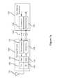
- FIG. 1 ais a block diagram of a general base station architecture that incorporates compression and decompression.
- FIG. 1 bis a block diagram of an example of a distributed antenna system (DAS) including compression and decompression.
- DASdistributed antenna system
- FIG. 2 ais a block diagram of compression and decompression in a base station modeled after OBSAI standard.
- FIG. 2 bis a block diagram of compression and decompression in an OBSAI compliant BTS having remote RF units.
- FIG. 2 cis a table of the wireless modulation formats supported by the OBSAI standard, in accordance with the prior art.
- FIG. 3 ais a block diagram of compression and decompression in a base station modeled after the CPRI standard.
- FIG. 3 bshows a radio base station system 300 where the REC 320 and multiple radio equipments 310 a and 310 b are connected in a chain arrangement via data transfer links 340 a and 340 b.
- FIG. 4is a block diagram of compression and decompression where multiple signal channels are compressed and multiplexed before transfer over a serial data link.
- FIG. 5illustrates an example of mapping a compressed data packet to the payload portion of an RP3 message.
- FIG. 6illustrates an example of mapping a compressed data packet to an Ethernet MAC frame and then to RP3 messages.
- FIG. 7is a table showing three numerical examples for mapping compressed data to Ethernet payloads.
- FIG. 8shows an example of mapping compressed data packets for transfer according to the CPRI protocol.
- FIG. 9 ais a block diagram of the compressor at the baseband unit.
- FIG. 9 bis a block diagram of the compressor at the RF unit.
- FIG. 10 ais a block diagram of the decompressor at the RF unit.
- FIG. 10 bis a block diagram of the decompressor at the baseband unit.
- FIG. 11gives examples that illustrate principles underlying alternatives for compressing signal samples with different center frequencies.
- FIG. 12is a block diagram of a compression algorithm based on the center frequency signal samples.
- FIG. 13shows the operations that produce modified sample based on the center frequency.
- FIG. 14gives the sums or differences of signal samples x(i) and x(i ⁇ j) for the examples of FIG. 11 .
- FIG. 15is a block diagram of the operations performed by the decompressor.
- Example architecturesinclude compression and decompression in a general base station, OBSAI or CPRI base stations and distributed antenna systems. The preferred methods for compression and decompression applied to the signal samples processed by the transceiver systems are then described.
- FIG. 1 ais a block diagram of a general base station architecture that incorporates compression and decompression in accordance with the present invention.
- the BTS architectureincludes the base station processor 100 connected by one or more serial data links 140 to a RF unit 150 .
- This general architecturecan be used for any air interface standard employed by wireless communication network, including GSM/EDGE, CDMA based modulation formats, OFDM based modulation formats such as WiMax and other signal modulation formats that may evolve.
- the remote RF unit 150can be located near the antenna 155 on an antenna tower.
- the RF unit 150can be connected to multiple antennas for transmission, reception, diversity or beamforming.
- the serial data link 140can be implemented by fiber optic, coaxial cable or RJ-45 twisted pair.
- the base station processor 100performs signal processing functions to prepare data for transmission by the RF unit 150 or recover data from signal samples received from the RF unit 150 .
- the types of functionsinclude symbol modulation/demodulation, channel encoding/decoding, spreading/despreading for CDMA, diversity processing for transmission/reception, interference cancellation, equalization, time and frequency synchronization, upconverting/downconverting, multiplexing/demultiplexing and data transport to/from an external network (not shown).
- the base station processor 100performs the signal processing functions to modulate communication data that were extracted from previously received wireless signals or received from an external network to produce digital signals.
- the signal processing functionsdepend on the modulation format and can include symbol modulation, channel coding, spreading for CDMA, diversity processing for transmission, time and frequency synchronization, upconverting, multiplexing, and inverse discrete Fourier transformation for OFDM.
- the digital signalsmay have a center frequency of 0 Hz, an intermediate frequency (IF) or a radio frequency (RF), depending on the system design.
- the compressor 120compresses the samples of the digital signal prior to transfer over a serial data link 140 to the RF unit 150 .
- the decompressor 125decompresses the compressed samples to reconstruct the digital signal before digital to analog conversion.
- the digital to analog converter (DAC) 160converts the reconstructed digital signal to an analog signal.
- the transmitter 182prepares the analog signal for transmission by the antenna 155 , including up-conversion to the appropriate radio frequency, RF filtering and amplification.
- antenna 155 at the RF unit 150receives an RF analog signal representing modulated communication data from one or more wireless sources, or subscribers.
- the frequency band of the received signalcan be a composite of transmitted signals from multiple wireless subscribers.
- the different subscriber signalscan be assigned to certain frequency channels or multiple subscribers can be assigned to a particular frequency band.
- the multiple subscriber signalsare assigned to a particular frequency band and each subscriber signal is spread across the band using a unique spreading code.
- the receiver 180performs analog operations on the RF analog signal, including RF filtering, amplification and down-conversion to shift the center frequency of the received signal from RF to an IF or 0 Hz, depending on system design
- the analog to digital converter (ADC) 170converts the received analog signal to a digital signal to produce signal samples that have only real values or, alternatively, have in phase (I) and quadrature (Q) components, based on system design.
- the compressor 130is applied to the entire bandwidth of the digital signal output from the ADC 170 .
- the compressor 130compresses the digital signal samples before transmission over the serial data link 140 .
- the decompressor 135decompresses the compressed samples to reconstruct the digital signal prior to performing the normal signal processing to recover communication data from the decompressed digital signal.
- the processing operationscan include demodulating symbols, channel decoding, despreading (for CDMA modulation formats), diversity processing, interference cancelling, equalizing, time and frequency synchronization, downconverting, demultiplexing, discrete Fourier transformation (for OFDM modulation formats) and transporting data derived from the decompressed signal samples to an external network.
- the base station processor 100 and RF unit 150may be referred to by other names in the art and do not limit scope of the present invention, as described in the claims.
- FIG. 1 bis a block diagram of an example of a distributed antenna system (DAS).
- the base station processor 100is connected to a plurality of remote RF units 150 and their associated antennas 155 .
- the DAScan have a plurality of remote RF units 150 that typically are located tens to hundreds of meters from the base station processor 100 .
- the base station processor 100is part of a main transceiver system, such as the BTS shown in FIG. 1 a , that typically has collocated RF.
- the main transceivermay be located on the roof of a building, for example.
- Each remote RF unit 150includes a compressor 130 , decompressor 125 , ADC 170 , DAC 160 , transmitter 182 and receiver 180 , although these components are represented in only one remote RF unit 150 for simplicity.
- the base station processor 100is connected to the remote RF units 150 via a hub 146 .
- the hub 146is then connected via data link 142 to another hub 148 or via links 144 to a plurality of remote RF units 150 .
- These data links 140 , 142 and 144may have identical characteristics or may be different depending on the system design.
- the base station processor 100applies the compressor 120 to compress signal samples.
- the compressed samplesare transferred via data link 140 to the hub 146 , via data link 142 to another hub 148 and via data links 144 to a plurality of remote RF units 150 .
- Compressed datacan remain compressed when passing through the hubs 146 and 148 .
- the decompressor 125decompresses the signal before digital to analog conversion 160 .
- the transmitter 182processes the resulting analog signal for transmission via antenna 155 .
- each antenna 155provides an analog signal to the receiver 180 .
- the ADC 170converts the received analog signal to a digital signal.
- the compressor 130compresses the digital signal before transfer via the appropriate data link 140 , 142 or 144 and hubs 148 and 146 to the base station processor 100 .
- the decompressor 135decompresses the compressed signal samples to reconstruct the received digital signal before conventional signal processing by the base station processor 100 .
- Distributed antenna systemsmay transfer IF or RF digital signals over the data links 140 , 142 and 144 , as described with respect to FIG. 1 a , or may transfer digital baseband signals as further described in the following.
- the compressor 120 / 130packs the compressed samples in compressed data packets having a format compatible with the data transfer protocol of the serial data link.
- the compressor 120 / 130adds a header portion to some or all of compressed data packets.
- the headercan be encoded in overhead bits, if available for the data transfer protocol.
- the header portionhas a defined length and includes synchronization and control information for the decompressor 125 / 135 .
- the compressor 120 / 130may pack the compressed samples in any order; however the decompressor 125 / 135 will reorder and format the decompressed samples to comply with the data representation format expected by the BTS.
- the serial data linkmay have a proprietary data transfer protocol or a standard protocol, such as Ethernet.
- the compressed data packet sizeis set to accommodate the data transfer protocol.
- the compressed data packetcan be sized to fit into the payload portion, as described below with respect to FIGS. 6 and 7 .
- the decompressor 125 / 135receives Ethernet MAC frame and extracts the compressed data packet from the payload portion.
- the decompressor 125 / 135extracts the synchronization and control information from the header for decompressing and reconstructing the sequence of signal samples.
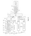
- FIG. 2 ais a block diagram of compression and decompression in a base station modeled after OBSAI standard.
- the OBSAI standardspecifies processing and transfer of baseband I and Q signal samples.
- the base station 200includes a baseband module 210 and a RF module 250 connected via one or more RP3 serial data links 240 . There can be multiple baseband modules 210 in communication with multiple RF modules 250 .
- the OBSAI architecturesupports the air interface standards for GSM/EDGE, CDMA, WCDMA and WiMax for fixed or mobile access having configurations listed in Table 1 of FIG. 2 c .
- the OBSAI standardcan also accommodate other wireless network configurations or signal modulation formats by incorporating general purpose modules.
- the baseband module 210performs signal processing functions on baseband signal data appropriate for the modulation format.
- the signal processing functionscan include symbol modulation/demodulation, channel coding/decoding, spreading/despreading, diversity processing for transmission/reception, interference cancellation, equalization, time and frequency synchronization, inverse/forward discrete Fourier transform, as appropriate for the air interface standard or other modulation format, and data transport to/from an external network (not shown).
- the RF module 250may contain transmit functionality only, receive functionality only, or both transmit and receive functionalities.
- the OBSAI RF module functionsinclude ADC/DAC, up/down conversion, carrier selection, antenna interface, Tx/Rx RF filtering, RF combining, diversity Tx/Rx and air interface functions.
- Options for the serial data links 240include fiber optic cable, copper cable or wireless transmission.
- the RP3 bus protocoldefines the data format and line coding for data transfer. Both the baseband module 210 and the RF module 250 format the compressed data for transfer in accordance with the RP3 bus protocol.
- the baseband module 210For the transmit path, or downlink, the baseband module 210 performs various functions on communication data appropriate for the modulation format to generate baseband signal samples 241 .
- the functionscan include symbol modulation, channel coding, spreading, transmit diversity processing and inverse discrete Fourier transform as appropriate for the OBSAI supported or other signal modulation format.
- the compressor 120compresses signal samples 241 before transfer via the serial data link 240 to the RF Module 250 .
- the decompressor 125decompresses the compressed samples to form decompressed signal samples 242 prior to the normal processing for RF transmission.
- the antenna 155receives analog RF signals representing modulated communication data from the subscribers.
- the operations of the RF module 250 to form the baseband digital signal samples 243will be described in more detail below with respect to FIG. 4 .
- the compressor 130compresses the digital signal samples 243 prior to transfer via serial data link 240 to the baseband module 210 .
- the decompressor 135decompresses the compressed samples to form decompressed signal samples 244 .
- the baseband module 210then applies the signal processing appropriate for the modulation format to the decompressed signal samples.
- the signal processing functionscan include symbol demodulation, channel decoding, despreading, receive diversity processing, interference cancellation, equalization, time and frequency synchronization, forward discrete Fourier transform, as appropriate for the air interface standard or other modulation format.
- FIG. 2 adepicts a point-to-point arrangement other connection arrangements are possible, including mesh topologies, bridge connections and combiner/distributor connections.
- FIG. 2 bis a block diagram of compression and decompression in an OBSAI compliant BTS having remote RF units.
- the base station 200is connected to two remote RF units (RRUs) 260 - 1 and 260 - 2 .
- the serial data links 250 - 1 and 250 - 2comply with the RP3-01 serial data link protocol as defined by the OBSAI specification.
- the RP3-01 protocolextends the RP3 protocol to accommodate physical layer technologies suitable for transporting data over longer physical links.
- a local converter (LC)implemented as a separate module or integrated with the BTS 200 or RRU 260 , maps data to the RP3-01 data format.
- the RP3-01 protocoluses the Ethernet MAC frames in accordance with the standard IEEE 802.3-2002.
- a point-to-point Ethernet transferis applied between the RP3-01 nodes, whether between RRUs 260 - 1 and 260 - 2 or between BTS 200 and RRU 260 - 1 .
- the RRU 260 - 1includes an Ethernet switch that determines whether a data frame is consumed at that RRU 260 - 1 or forwarded to the RRU 260 - 2 .
- the baseband module 210compresses the payload signal data prior to transfer over the data link 250 - 1 in accordance with the RP3-01 protocol. If the RRU 260 - 1 is the destination node, the RRU 260 - 1 decompresses the compressed data prior to processing for RF transmission from antenna 255 - 1 .
- the RRU 260 - 1passes the data frame with the compressed payload data over link 250 - 2 to RRU 260 - 2 .
- the RRU 260 - 2decompresses the compressed payload data for transmission from antenna 255 - 2 .
- the RRUs 260 - 1 and 260 - 2compress their respective received signal samples and format the compressed signal data for transfer in accordance with RP3-01 protocol.
- the baseband module 210decompresses the compressed signal data received from the RRUs 260 - 1 and 260 - 2 prior to the normal baseband operations.
- the RRU 260 - 1will pass the data frames it received from RRU 260 - 2 to the BTS 200 without decompressing the payload data.
- FIG. 3 ais a block diagram of compression and decompression in a base station modeled after the CPRI standard.
- the CPRI standardspecifically supports UTRA/FDD standard (Universal Terrestrial Radio Access/Frequency Division Duplex, uses WCDMA modulation format) and WiMax standard (IEEE802.16-2004 and IEEE802.16e-2005) but can also be used for other air interface modulation formats.
- the radio base station system 300includes the radio equipment control (REC) 320 and the radio equipment (RE) 310 . These two components are connected via serial data links 340 comprising bidirectional links using wire or fiber optic media.
- the REC 320performs signal processing functions on baseband signal samples, including channel coding/decoding, interleaving, spreading/dispreading (UTRA/FDD) and inverse/forward discrete Fourier transform (WiMax).
- the RE functionsprepare signal samples for the air interface or generate signal samples from the received analog signal, including ADC/DAC, up/down conversion, carrier multiplexing/demultiplexing, Tx/Rx amplification and RF filtering.
- the RE 310is connected to one or more antennas 155 .
- the CPRI standardindicates 1 , 2 or 6 antennas per RE with 1-4 carriers per antenna.
- the compressor 120compresses signal samples 341 a before transfer via the serial data link 340 to the RE 310 .
- the decompressor 125decompresses the compressed signal data to produce decompressed signal samples 342 a .
- the decompressed signal samples 342 aare further processed for transmission over antenna 155 .
- the RE 310processes signals received by the antenna 155 to form baseband digital signal samples 343 a .
- the compressor 130compresses the samples before transfer via the serial data link 340 .
- the decompressor 135decompresses the received compressed samples to form decompressed samples 244 a .
- the REC 320performs the normal processing functions on the decompressed samples 244 a .
- the functions of the RE 310 and REC 320are further described below with respect to FIG. 4 .
- FIG. 3 ashows a point-to-point link between the REC 320 and the RE 310 .
- Other topologiesinclude multiple point-to-point links between REC 320 and RE 310 and multiple point-to-point links between one REC 320 and more than one RE 310 .
- FIG. 3 bshows a radio base station system 300 where the REC 320 and multiple radio equipments 310 a and 310 b are connected in a chain arrangement via data transfer links 340 a and 340 b .
- Other topologies where REs connect to each otherinclude tree, ring, and star.
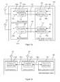
- FIG. 4is a block diagram of compression and decompression where multiple signal channels are compressed and multiplexed before transfer over a serial data link.
- Both OBSAI and CPRI transceiversreceive and transmit multiple frequency channels of signal samples for each independent antenna, or multiple antenna-carriers. In this example, there are four channels of signal samples representing four antenna-carriers.
- the signal samplescomprise baseband I and Q samples.
- each compressor 120 i in the baseband unit 110independently compresses a stream of baseband I,Q signal samples to form corresponding streams of compressed samples.
- the multiplexer 420multiplexes the compressed samples into a single serial data stream for transfer over serial data link 430 in accordance with the standard.
- the demultiplexer 440demultiplexes the serial data stream to recover the four streams of compressed samples in accordance with the standard.
- Each decompressor 125 idecompresses one stream of compressed samples to reconstruct the corresponding baseband I,Q signal samples.
- the digital upconverter (DUC) 461upconverts each stream of decompressed signal samples to respective carrier frequencies to form a channelized signal. Each upconverted digital signal occupies a particular channel of the resulting channelized signal.
- the DAC 460converts the channelized signal to an analog signal.
- the transmitter 480converts the analog signal to the appropriate RF frequency for transmission by the antenna 155 .
- the receiver 482receives the RF signal and the ADC 470 digitizes the received signal to produce a digital signal that represents a channelized signal data as described for the transmit path.
- the digital down converter (DDC) 471downconverts each channel to form corresponding streams of baseband I,Q signal samples, one for each channel.
- the compressor 130 icompresses its input signal samples to form compressed samples.
- the multiplexer 421multiplexes the streams of compressed samples output from the compressors to form a serial data stream in accordance with the OBSAI or CPRI standards.
- the serial data streamis transferred via the serial data link 430 to the baseband unit 110 .
- the demultiplexer 441demultiplexes the serial data to restore the four streams of compressed samples.
- Each decompressor 135 ireconstructs the corresponding I,Q signal samples prior to the normal operations by the baseband processor 410 .
- the compressors 120 i and 130 iorganize the compressed samples into compressed data packets compatible with the OBSAI, CPRI or other protocols.
- the compressed data packetsrepresent compressed I and Q samples.
- the order of the compressed samplesmay be sequential interlaced compressed I and Q samples, i.e. (I 1 Q 1 I 2 Q 2 . . . I N Q N ).
- the order of the compressed I and Q samplesmay have blocks of compressed I samples followed by blocks of compressed Q samples, i.e. (I 1 I 2 . . . I N Q 1 Q 2 . . . Q N ).
- the compressors 120 i / 130 ioperate on blocks of consecutive input signal samples having a length of BLOCK_SIZE.
- the compressor 120 i / 130 icompresses BLOCK_SIZE consecutive samples and forms a compressed data packet.
- a useful BLOCK_SIZEis 192, although other block sizes can be used.
- the block size of 192 samplesprovides for simple double-buffered input blocks for field programmable gate arrays (FPGA).
- a smaller block sizesuch as 4 to 8 samples, can be implemented to meet the more stringent latency requirements of the OBSAI and CPRI specifications.
- the block size in samplesshould span a time period that is less than or equal to half the allowable latency period. This assumes that half of the latency is consumed for compression and the other half for decompression.
- the CPRIspecifies an allowable latency period of 5 ⁇ sec.
- the allowable latency of 5 ⁇ sec.spans about 19 sample intervals.
- a block size of 4 sampleswill have a latency period of 8 sample intervals which is well within the allowable latency period for CPRI.
- the compressor 120 i / 130 imay add a header portion to some or all of the compressed data packets.
- the header portionhas a defined length, for instance 16 bits.
- the header informationcan placed in overhead fields of the OBSAI or CPRI message format.
- header informationcan be encoded using unused codes of an OBSAI message's TYPE field.
- header informationcan be encoded in stuffing bits of the basic frame.
- the compressor 120 i / 130 iprovides the compressed data packet to the payload portion of the OBSAI or CPRI message format.
- the decompressor 125 i / 135 ireceives the OBSAI or CPRI message and extracts the compressed data packet from the payload portion.
- the decompressor 125 i / 135 iuses the header to extract control parameters for decompression and to establish compressed data packet synchronization.
- the decompressor 125 i / 135 ireconstructs the sequence of I,Q signal samples in the I and Q sample order, byte order and data format specified by the OBSAI, CPRI or other protocol. Control messages used by OBSAI or CPRI are not compressed.
- the OBSAI standard's RP3 and RP3-01 bus protocolsinclude features useful for transfer of compressed data packets.
- the OBSAI application layer message formathas a fixed size of 19 bytes, or 152 bits, including 3 bytes allocated for address/type/timestamp and 16 bytes, or 128 bits, allocated for payload.
- the type fieldsinclude W-CDMA/FDD, W-CDMA/TDD, 802.16, LTE and Ethernet.
- a compressed data packetcan be set to a length of 128 bits to fit the payload portion.
- the OBSAI physical layerapplies 8b10b encoding to each byte of the message, including the payload, prior to transfer over the data link.
- the RP3 protocoldefines a message group that includes up to 65,536 messages and up to 20 idle bytes and a frame including up to an integer multiple times 65 , 536 consecutive message groups, where the integer multiple is 1, 2 or 4.
- the time interval for a frameis fixed at 10 msec.
- FIG. 5illustrates an example of mapping a compressed data packet to the payload portion 522 of an RP3 message 520 .
- the type field 524indicates the data type of the signal samples, for example W-CDMA/FDD.
- the address 526is used for routing at the transport layer.
- the transport layer functionincludes the message multiplexer 528 that multiplexes RP3 message 520 with other RP3 messages (not shown) in accordance with the system configuration and routing requirements.
- the message group formatter 530assigns multiple messages to message slots and adds control data and idle bytes to form a message group.
- the 8b10b encoder 540encodes each byte to 10 bits to form a portion of the bit stream for transfer over the serial data link. Referring to FIG. 4 , for OBSAI systems, the multiplexers 420 and 421 perform the functions described with respect to FIGS. 5 and 6 on the compressed data packets 510 from each group of compressors 120 i and 130 i .
- the demultiplexers 440 and 441perform the inverse operations, including 8b10b decoding, message demultiplexing and extracting the payload data from the RP3 message 520 to retrieve the compressed data packet 510 .
- the payload data from the Ethernet MAC frame 550is reassembled from the payload data from RP3 packets 630 - 1 to 630 - n .
- the compressed data packet 510is retrieved from the payload data of the Ethernet MAC frame 550 .
- a 10 msec. OBSAI frameaccommodates 38,400 chips for W-CDMA signals.
- the user data transferred during 10 msec.have 6.144 Mbits, 12.288 Mbits, and 24.576 Mbits.
- a 768 Mbps linkcan carry 4 antenna-carriers (16 bits I, 16 bits Q).
- the 768 Mbps linkwill carry 8 antenna-carriers.
- Ethernet MAC frame sizesare between 64 bytes and 1518 bytes, with 14 bytes for the header and payload sizes between 46 bytes and 1500 bytes.
- FIG. 6shows an example of mapping a compressed data packet to Ethernet MAC frames and then to RP3 messages.
- the compressed data packet 510is mapped to the payload portion of an Ethernet MAC frame 550 .
- the contents of the Ethernet MAC frame 550are then mapped to the payload portion of several RP3 messages 630 - 1 to 630 - n .
- the functions of multiplexing at the transport layer, formation of message groups at data link layer and the 8b10b encoding at the physical layerproceed as described with respect to FIG. 5 .
- the BLOCK_SIZE for compressed datacan be any multiple of 4.
- the table in FIG. 7gives three numerical examples for mapping compressed data to Ethernet payloads. The bits per sample indicate the number of bits allotted to each I sample and each Q sample. The assumed BLOCK_SIZE and resulting number of payload bytes per Ethernet MAC frame are listed.
- the samples per payload value of 750assume no bit-packing.
- the BLOCK_SIZE for compressed datacan be selected by a user to achieve a desired Ethernet payload size.
- the OBSAI standardalso supports custom data types for RP3 messages. Since type values 01111-11111 are not assigned, the user can assign one of the type values to a custom message that contains compressed data in the payload portion. Referring to FIG. 5 , the type field 524 can be assigned the type value corresponding to the custom message. The user can specify additional parameters for message groups containing custom messages, including the number of message per message group (M_MG), the minimum number of message groups per frame (N_MG) and the number of idle codes per message group (K_MG).
- M_MGmessage per message group
- N_MGminimum number of message groups per frame
- K_MGnumber of idle codes per message group
- the CPRIdefines a basic frame having a duration of 260.416667 nanoseconds, or 1/3.84 MHz.
- the basic frameincludes 16 words, one word contains control data and the remaining 15 words, referred to as the IQ data block, contain baseband I,Q signal samples.
- the word length in bitsdepends on the data transfer rate of the link.
- the IQ data block size in bitsequals 15 times the word length, so capacity of a basic frame depends on the data transfer rate.
- the specified data transfer ratesare 614.4 Mbps, 1228.8 Mbps, 2457.6 Mbps and 3072.0 Mbps with respective word lengths of 8, 16, 32 and 40 bits.
- the CPRI standardallows varying sample widths for signal samples for the downlink (8 to 20 bits per sample) and the uplink (4 to 20 bits per sample).
- the sample widthis the number of bits per sample.
- Each I,Q signal sampleconsists of one I sample having the sample width and one Q sample having the same sample width.
- the sample widthsare determined at the application layer. The flexibility of sample width is beneficial for accommodating compressed samples.
- the CPRI protocolorganizes signal data into packets called AxC containers.
- Each AxC containerincludes I and Q samples corresponding to one antenna-carrier (AxC).
- the AxCcorresponds to data provided to or received via one carrier of one independent antenna element.
- the AxC containerholds the I,Q samples for the duration of one UMTS chip. For WiMax, the AxC container holds the I,Q samples and sometimes additional stuffing bits.
- the AxC containers from several different AxCsare multiplexed together to form AxC container groups.
- the AxC container groupsare mapped to the I,Q data block of the basic frame.
- FIG. 8shows an example of mapping compressed data packets for transfer according to the CPRI protocol.
- Each compressed data packet 510 from the same antenna-carrieris mapped to an AxC container 610 .
- the consecutive AxC containers AC0-1 and AC0-2correspond to a first antenna-carrier, AxC#0.
- Each AxC container 611holds a compressed data packet from a second AxC, AxC#1.
- the multiplexer 620multiplexes the AxC containers from the two antenna-carriers to form an AxC container group 625 .
- the basic frame formatter 630forms a basic frame having a number of AxC container groups in the IQ data block and adding the control word.
- the 8b10b encoder 540applies an 8b10b code to each byte of data in the basic frame.
- the multiplexers 420 and 421perform the functions described with respect to FIG. 8 on compressed data packets 510 output from each group of compressors 120 i and 130 i .
- the demultiplexers 440 and 441perform the inverse operations, including 8b10b decoding, demultiplexing AxC containers from the AxC container groups and extracting the compressed data packets 510 from the AxC containers.
- the CPRI standardsupports between 4 and 24 AxCs per RE.
- the CPRI standardalso specifies oversampling the received analog signal by factors of 2 to 4 for the UTRA/FDD uplink. Compressing the oversampled signals reduces signal redundancy. Compression could enable the use of fewer media connections (cables) between RECs and REs, lowering physical connection costs and allowing existing CPRI links to support additional AxCs.
- the serial data transfer link 430can be implemented using several types of cabling or using wireless transmission. For long distances single mode or multi-mode fiber optic cabling may be used, while for shorter links CAT5/6, other twisted pair cabling, or coax may be used. Multiple RF bands transmitted as digital data streams can be time multiplexed on optical fiber links.
- Oversamplingis indicated when the number of samples per symbol or chip is greater than one.
- the oversampling ratiois the ratio of the sample rate to the symbol rate or chip rate.
- the oversampling ratiois greater than one, the signal is oversampled.
- the CPRI standardspecifies sampling the received analog signal with an oversampling ratio 2 or 4 samples per chip for the UTRA/FDD uplink.
- the OBSAI standardspecifies oversampling the uplink WCDMA signal by an oversampling ratio of 2 samples per chip
- lossy compressioncan be applied to the signal samples while maintaining system quality metrics.
- the decompressed signal samplesare identical to the original signal samples.
- the decompressed signal samplesare approximations of the original signal samples.
- System quality metricstypically include composite error vector magnitude (cEVM), peak code domain error (PCDE), spectral emissions mask (SEM), adjacent channel leakage ratio (ALCR), bit error rate (BER) and block error rate (BLER).
- cEVMcomposite error vector magnitude
- PCDEpeak code domain error
- SEMspectral emissions mask
- ACRadjacent channel leakage ratio
- BERbit error rate
- BLERblock error rate
- the oversampling and/or sample widths of the signal samplesmay be greater than necessary to meet system requirements for signal quality. Lossy compression can provide a greater reduction in data transfer capacity while the important metrics of signal quality are preserved.
- Systems that generate baseband signal samples for transfer over the serial data linksinclude those compatible with OBSAI or CPRI and configurations of the general BTS where the signal samples are centered at 0 Hz.
- the compression methods applied to baseband signal samplesinclude block floating point encoding and computing first or higher order derivatives of the signal samples followed by block floating point encoding. Huffman or other types of encoding can be alternatives to block floating point encoding.
- the preferred methodis block floating point encoding of the signal samples.
- the OBSAI compatible W-CDMA signal samples for downlink from the baseband module to the RF unithave one sample per chip.
- the block floating point encodingis applied to the I samples and, independently, to the Q samples, to form the compressed samples.
- the preferred block floating point encodinghas the following steps for BLOCK_SIZE samples, each BLOCK_SIZE divided into groups of N_group samples:
- the exponent n_exp(0)is absolute encoded.
- the exponent n_exp(0)can be encoded as follows, where S is the original number of bits per sample:
- the exponent n_exp(i)is differentially encoded using a prefix code, where no codeword is the prefix of another codeword.
- the preferred differential encodingis as follows:
- Another compression alternative for baseband signal samplesis calculating differences followed by encoding. Calculating first or higher order differences of the signal samples can result in difference samples having smaller magnitudes than the original signal samples. Encoding the difference samples can result in greater compression than encoding the samples themselves. Calculating the differences of consecutive samples in each BLOCK_SIZE number of samples is followed by block floating point encoding of the difference samples, as described above. Alternatively, Huffman encoding or other encoding can be applied to the difference samples.
- Compressioncan also include reducing the amplitudes of signal samples. This is a form of lossy compression. Attenuating the signal samples by an attenuation factor reduces the effective sample width.
- the attenuated signal samplescan be encoded by block floating point or other encoding. Alternatively, the first or higher order differences of the attenuated signal samples can be calculated prior to encoding. For decompression, the amplitudes of the decompressed samples can be increased by the inverse of the attenuation to restore the original sample width.
- the optimum compression for the wireless communication signals that meets system quality requirements for the BTScan be determined in advance.
- the compression alternativescan include lossless and lossy compression.
- Control parameters based on the modulation type, sample rate (or oversampling ratio), bandwidth and sample widthcan be used to configure the compression and decompression operations.
- the control parameters for the various types of signals served by the BTScan be determined by testing.
- the control parameterscan then be set based on the modulation type. For example, in the OBSAI standard the type field in the RP3 message indicates the signal type, or modulation type. Since the OBSAI standard specifies the sample rate and sample width based on the modulation type, a compression/decompression controller can use the type information to select the corresponding control parameters for the compressor/decompressor.
- the usercan also select lossless or lossy modes. For instance, selecting an attenuation parameter for reducing the amplitudes of the signal samples will result in lossy compression.
- the usercan also select a fixed-rate lossy mode, where the bit rate of the compressed samples is constant.
- FIGS. 9 a and 9 bshow block diagrams of the compressors 120 i and 130 i of FIG. 4 .
- the compressor 120 ireceives input from the baseband processor 410 and the compressor 130 i receives input from the DDC 471 .
- the compressors 120 i / 130 iinclude the respective compression controllers 126 / 136 that provide control parameters for the respective difference operators 122 / 132 and encoders 124 / 134 .
- the application layer for the base station processor and the RF unitincludes the air interface applications for the types of wireless signals. For example, in the OBSAI standard, the application layer determines the signal type, or modulation type, and encodes it for the type field of the RP3 message.
- the compression operations of the present inventionare added to the conventional operations of the application layer, so information on the modulation type is available to the compression controllers 126 / 136 .
- the compression controllers 126 / 136use the modulation type information to determine control parameters for the respective difference operators 122 / 132 and encoders 124 / 134 .
- the control parameters for the difference operators 122 / 132can select first, second or higher order differences, or bypass the difference operations.
- the control parameter for the encoders 124 / 134can indicate parameters for the block floating point encoder, such as number of bits S, the group size and BLOCK_SIZE.
- FIGS. 10 a and 10 bare block diagrams of the decompressors 125 i and 135 i of FIG. 4 .
- the decoders 127 / 137invert the operations of the encoders 124 / 134 to form decoded samples. For example, the decoders 127 / 137 perform block floating point decoding, Huffman decoding or other decoding.
- the integration operators 129 / 139add the decoded difference samples to invert the first or higher order differencing performed for compression. If differencing was not performed for compression, the integration operators 129 / 139 would be bypassed.
- the decompression controllers 123 / 133provide control parameters to the respective decoders 127 / 129 and integration operators 129 / 139 .
- the decompression controllers 123 / 133can extract control data from the header of the compressed data packet to determine the control parameters.
- the decompression controllers 123 / 133can also use modulation type information to determine the appropriate decompression configuration.
- the modulation type informationcan be included in the header. For OBSAI the modulation type can be determined from the type field of the RP3 messages.
- the compression and decompression described abovecan also be applied to signal samples having non-zero center frequencies.
- the compressors 120 / 130 and decompressors 125 / 135 of FIGS. 1 a and 1 b for the general BTS architecturecan apply block floating point encoding or differencing followed by encoding, as described above, to signal samples centered at IF or RF. Compression can also include attenuating the signal samples as described above.
- the alternative compression algorithms described belowmay achieve better compression for signal samples having non-zero center frequencies.
- the sample rateis represented by f s and the sample interval is the inverse of the sample rate, 1/f s .
- the signal samplescan represent multiple channels of signal data centered at an RF or converted to an IF in a block, or band, of frequencies.
- the compressors 120 / 130 and decompressors 125 / 135process the block of frequencies as a unit.
- FIG. 11gives examples that illustrate principles underlying alternatives for compressing signal samples with different center frequencies.
- the center frequencyis near DC (0 Hz) and the phase increase between consecutive samples is less than 10 degrees.
- the first phasor diagram 710shows that since the phase changes between consecutive samples are small, the magnitudes of the differences of consecutive samples will be relatively small compared to the magnitudes of the samples themselves.
- the first example sequence 712corresponds to samples of a Band 1 baseband signal. Since the differences between consecutive samples are small relative to the sample magnitudes, calculating first or higher order differences, or differential encoding, creates difference samples with smaller data widths than the original samples. Compression using differential encoding approach is effective for the baseband (Band 1 ) example. This corresponds with the compression approach described with respect to FIGS. 9 a and 9 b for baseband signal samples.
- FIG. 11also gives examples of sampled signals where the center frequency is above DC, but below the Nyquist frequency, f s /2.
- the center frequencyis near f s /6 and the phase increase between consecutive samples is about 60 degrees.
- the second phasor diagram 720shows that pairs of samples separated by 180 degrees, or three sample intervals, have similar magnitudes but opposite polarities, as illustrated by pairs of samples ( 720 - 0 , 720 - 3 ), ( 720 - 1 , 720 - 4 ) and ( 720 - 2 , 720 - 5 ). Inverting one of the samples in the pair [or multiplying by ( ⁇ 1)] provides a close estimate of the other sample in the pair.
- the second example sequence 722also shows that samples separated by three sample intervals have similar magnitudes and opposite signs. For example, the value of sample 722 - 0 is 32767 and the value of sample 722 - 3 is ⁇ 32756.
- For Band 2operations on pairs of samples separated by three sample intervals produce modified samples with smaller data widths. The operation of adding the samples in the pair together produces modified samples having smaller data widths that can be encoded more efficiently.
- the center frequencyis near f s /4 and the phase increase between consecutive samples is about 90 degrees.
- the third phasor diagram 730shows that samples separated by 180 degrees, or 2 sample intervals, have similar magnitude and opposite polarity.
- the third example sequence 732also shows that every other sample has similar magnitudes and opposite polarities. For Band 3 , adding together every other sample will result in modified samples with smaller data widths that can be encoded more efficiently than the original samples.
- the center frequencyis near f s /3 and the phase increase between consecutive samples is about 120 degrees.
- the fourth phasor diagram 740shows that samples separated by 360 degrees, or 3 sample intervals, will have similar magnitudes.
- the fourth example sequence 742shows that every third sample has similar magnitudes. In this case, forming a difference between samples separated by 3 sample intervals will give a modified sample with a smaller data width that can be encoded more efficiently than the original samples.
- the center frequencyis f s /2 and the phase increase between consecutive samples is about 180 degrees.
- the fifth phasor diagram 750shows that samples separated by 180 degrees, or one sample interval, will have similar magnitudes but opposite polarities.
- the fifth example sequence 752shows consecutive samples have similar magnitudes and opposite polarities. In this case, adding two consecutive samples will form a modified sample with a smaller data width that can be encoded more efficiently than the original samples.
- magnitude reductioncan be achieved by performing operations such as addition (or inversion followed by subtraction) or subtraction (or inversion followed by addition) on signal samples that are separated by 1, 2 or 3 sample intervals, depending on the ratio of the sample rate to the center frequency.
- the resulting modified samplesare then encoded to form compressed samples. Similar operations can be applied to samples that are separated by four or more sample intervals, depending on the ratio of the center frequency to the sample rate, to produce modified samples with smaller data widths than the original signal samples.
- FIG. 12is a block diagram of a compression algorithm based on the center frequency of the signal samples.
- the ADC 170 or the base station processor 100provide I and Q signal samples to the respective compressors 120 or 130 .
- the reorder demux 810selects signal samples so that selected samples are separated by the appropriate number of sample intervals according to compression control parameter 852 to form demultiplexer output 812 .
- Arithmetic operator 830performs addition or subtraction operations on pairs of demultiplexer output samples 812 according to compression control parameter 856 to form modified samples 832 .
- Arithmetic operator 830can also be configured to perform higher order differences on the demultiplexer output samples 812 .
- the encoder 840encodes the modified samples 832 to form compressed signal samples.
- the encoder 840applies block floating point encoding, Huffman encoding or other encoding.
- the compressed signal samplesare packed and formatted for transfer over the serial data link 140 .
- the compression controller 860provides control parameters to the compressor elements based on the ratio of the sample rate to the center frequency of the signal samples.
- the reorder demux 810 and arithmetic operator 830respond to the compression control parameters 852 and 856 , respectively, to perform the appropriate operations.
- FIG. 13shows the operations that produce modified samples 832 based on the center frequency.
- the first column 871gives the possible center frequencies for this example.
- the second column 872gives a corresponding frequency band indicator for each center frequency.
- the indicatorscan be used as parameters for compression control parameters 852 and 856 .
- the third column 873gives the different separations of samples x(i) and x(i ⁇ j) at reorder demux output 812 that would be produced in accordance with compression control parameter 852 .
- the fourth column 874shows the result of selecting the arithmetic operations of addition or subtraction in accordance with compression control parameter 856 .
- the fifth column 875shows the mathematical results of the arithmetic operator 830 that produce the modified samples 832 , or y(i).
- the compression controller 860also provides control of the encoder 840 .
- the compression control parameter 858can indicate a parameter for block floating point encoding or other encoding technique.
- FIG. 14gives the sums or differences of signal samples x(i) and x(i ⁇ j) for the examples of FIG. 11 calculated as described with respect to of FIGS. 12 and 13 for different center frequencies.
- the example sequences of signal samplesare the same as those of FIG. 11 .
- the samples in the DIFF rows in example sequences 912 and 942 and the SUM rows in example sequences 922 , 932 and 952have substantially lower magnitudes than the corresponding signal samples, or x(i).
- the DIFF samples and the SUM samplesare examples of modified samples 832 that are input to encoder 840 in FIG. 12 .
- a multicarrier signalcomprising four 5 MHz channels for a total bandwidth of 20 MHz.
- the 20 MHz multicarrier signalis centered at an IF of 30.72 MHz and is sampled at a sample rate (f s ) of 122.88 MHz.
- the reorder demux 810rearranges the samples into two sequences, one with the odd-indexed samples and one with the even-indexed samples, so the samples in each sequence are separated by two sample intervals.
- the arithmetic operator 830adds the samples in each sequence in accordance with equation (1) to form the modified samples 832 .
- the encoder 440applies block floating point encoding to the modified samples to form the compressed samples.
- the compressed samplesare packed to form compressed data packets that include control data in a header, as described above.
- the compressed packetscan be further formatted in accordance with a protocol for transfer over the serial data link 140 .
- the serial data link 140can be a custom link or an industry standard link. Depending on the type of link, formatting operations can include 8b10b encoding, insertion into Ethernet MAC frame or other formatting.
- FIG. 15is a block diagram of the operations performed by the decompressors 125 / 135 .
- the compressed packetsare received by the decoder 910 from the data link 140 .
- the decoder 910unpacks and performs decoding operations, for instance block floating point decoding, on the compressed data, to form decoded modified samples.
- the inverse arithmetic operator 920performs the inverse operations to the arithmetic operator 830 to reconstruct the signal samples from the decoded modified samples.
- the multiplexer 930restores the original order of the decompressed signal samples.
- the decompressed signal samplesare converted to an analog signal and processed for transmission.
- the normal signal processing operationsare applied to decompressed signal samples.
- the compression methods described abovecan be configured to produce lossless or lossy compression. Depending on system parameters, it can be possible to obtain the specified bit error rates (BER), or other quality metric, for data transfer when lossy compression is applied to the signal samples. Lossy compression can provide additional resource savings within the BER limitation.
- One approach for lossy encodingis to reduce the data width, or dynamic range, of the samples to be compressed.
- a programmable attenuatorcan attenuate the signal samples to reduce the data width prior to the other compression operations of compressors 120 / 130 and 120 i / 130 i .
- programmable shifterscan shift out one or more least significant bits from the signal samples, also reducing the data width.
- arithmetic operator 830 or encoder 840can eliminate one or more least significant bits.
- Each of these alternatives for lossy encodingcan be controlled by the compression controller 860 .
- Additional alternatives for control of lossless and lossy compressioncan be based on a desired bit rate for compressed signal samples or a desired signal quality, such as SNR or BER, of the decompressed signal.
- the BTSincludes compression and decompression on both the forward link from the base station processor to the RF unit and the reverse link from the RF unit to the base station processor.
- Alternative embodimentsinclude providing compression and decompression in one direction only.
- the base station processorincludes a compressor and only the RF unit includes a decompressor.
- the reverse link, or up linkonly the RF unit includes a compressor and only the base station processor includes a decompressor.
- Implementation alternatives for the compressor and decompressorinclude programmable processors and application specific integrated circuits (ASIC).
- the programmable processorsinclude software/firmware programmable processors such as computers, digital signal processors (DSP), microprocessors (including microcontrollers) and other programmable devices, and hardware programmable devices such as complex programmable logic devices (CPLD), field programmable gate arrays (FPGA).
- DSPdigital signal processors
- CPLDcomplex programmable logic devices
- FPGAfield programmable gate arrays
- the program implementing the compression and decompression operationsare represented by software, firmware, netlist, bitstream or other type of processor executable instructions and data.
- Subsystems that implement the compressor and decompressorcan be integrated into devices that perform other functions of the RF unit or base station processor.
- Implementations of compression or decompressioncan be performed in real time, that is, at least as fast as the sample rate of the ADC or DAC.
- Compression and decompression operationsinclude multiplexing operations, inversion operations and simple arithmetic operations including addition, subtraction and shifting.
Landscapes
- Engineering & Computer Science (AREA)
- Theoretical Computer Science (AREA)
- Mobile Radio Communication Systems (AREA)
- Transmission Systems Not Characterized By The Medium Used For Transmission (AREA)
Abstract
Description
- compressing the signal samples of each baseband channel at the RF unit to form compressed samples in accordance with a compression control parameter, wherein each compressed sample includes a compressed I sample and a compressed Q sample;
- formatting the compressed samples for transfer over the serial data link;
- transferring the compressed samples over the serial data link from the RF unit to the baseband processor; and
- receiving the compressed samples at the baseband processor;
- decompressing the compressed samples corresponding to each baseband channel in accordance with a decompression control parameter to form decompressed signal samples of the corresponding baseband channel, wherein each decompressed signal sample includes a decompressed I sample and a decompressed Q sample, wherein the baseband processor applies the signal processing operations to the decompressed signal samples for each baseband channel.
- compressing the signal samples corresponding to each baseband channel at the baseband processor to form compressed samples in accordance with a compression control parameter wherein each compressed sample includes a compressed I sample and a compressed Q sample;
- formatting the compressed samples for transfer over the serial data link;
- transferring the compressed samples over the serial data link from the baseband processor to the RF unit;
- receiving the compressed samples at the RF unit; and
- decompressing the compressed samples in accordance with a decompression control parameter to form decompressed signal samples corresponding to each baseband channel, wherein each decompressed sample includes a decompressed I sample and a decompressed Q sample, wherein the decompressed signal samples are provided to the DUC for forming the upconverted digital signal.
- a plurality of compressors at the RF unit, each compressor coupled to receive the signal samples of a corresponding baseband channel output from the DDC and producing compressed samples in accordance with a compression control parameter, wherein each compressed sample includes a compressed I sample and a compressed Q sample;
- a formatter coupled to the plurality of compressors and formatting the compressed samples in accordance with a data transfer protocol;
- the serial data link coupled to the formatter for transferring the compressed samples to the baseband processor;
- the baseband processor coupled to the serial data link to receive the compressed samples; and
- a plurality of decompressors integrated into the baseband processor, each decompressor receiving the compressed samples of the corresponding baseband channel and forming decompressed signal samples in accordance with a decompression control parameter, wherein each decompressed signal sample includes a decompressed I sample and a decompressed Q sample, wherein the baseband processor performs the signal processing operations on the decompressed signal samples for each baseband channel.
- a plurality of compressors integrated into the baseband processor, each compressor compressing signal samples of a corresponding baseband channel in accordance with a compression control parameter to form compressed samples, wherein each compressed sample includes a compressed I sample and a compressed Q sample;
- a formatter coupled to the plurality of compressors and formatting the compressed samples in accordance with a data transfer protocol;
- the serial data link coupled to the formatter for transferring the compressed samples to the RF unit;
- the RF unit coupled to the serial data link to receive the compressed samples; and
- a plurality of decompressors at the RF unit, each decompressor receiving compressed samples of the corresponding baseband channel and forming decompressed signal samples, wherein each decompressed signal sample includes a decompressed I sample and a decompressed Q sample, wherein the decompressed signal samples are provided to the DUC for forming the upconverted digital signal.
- For the first group of samples, where S is the original number of bits per sample:
- 1) Determine the exponent (base 2) for the sample with the maximum magnitude, such as by calculating the log2of the maximum magnitude. This indicates the number of bits per encoded sample in the group, or n_exp(0).
- 2) Absolute encode the exponent n_exp(0) of the first group using S bits.
- 3) Encode the N_group samples using n_exp(0) bits per sample. For the ithgroup of N_group samples
- 4) Determine the ithexponent (base 2) for the sample with the maximum magnitude, which indicates the number of bits per encoded sample in the ithgroup, or n_exp(i);
- 5) Differentially encode the ithexponent by subtracting n_exp(i) from n_exp (i−1) to determine the first token in the ithgroup of encoded samples.
- 6) Encode the ithgroup of N_group samples using n_exp(i) bits per sample.
- a. 0: n_exp(0)=0 (all 4 sample values are zero)
- b. 1: n_exp(0)=2 (2 bits per sample)
- c. 2: n_exp(0)=3 (3 bits per sample)
- d. etc. until S−1: n_exp(0)=S (S bits per sample)
- 1. Calculate difference: e_diff=n_exp(i)−n_exp(i−1)
- 2. Encode e_diff as follows:
- a. 0: e_diff=e(i)−e(i−1)
- b. 101: e_diff=+1
- c. 110: e_diff=−1
- d. 1001: e_diff=+2
- e. 1110: e_diff=−2
- f. Etc.
y(i)=x(i)+x(i−2) (1)
as indicated in
Claims (41)
Priority Applications (4)
| Application Number | Priority Date | Filing Date | Title |
|---|---|---|---|
| US13/191,330US8705634B2 (en) | 2008-05-21 | 2011-07-26 | Compression of baseband signals in base transceiver systems |
| US13/243,154US8331461B2 (en) | 2008-05-21 | 2011-09-23 | Compression of baseband signals in base transceiver system radio units |
| US13/243,172US9240803B2 (en) | 2008-05-21 | 2011-09-23 | Compression of baseband signals in base transceiver system processors |
| US13/243,123US8320433B2 (en) | 2008-05-21 | 2011-09-23 | Compression of baseband signals in base transceiver system interfaces |
Applications Claiming Priority (2)
| Application Number | Priority Date | Filing Date | Title |
|---|---|---|---|
| US12/124,382US8005152B2 (en) | 2008-05-21 | 2008-05-21 | Compression of baseband signals in base transceiver systems |
| US13/191,330US8705634B2 (en) | 2008-05-21 | 2011-07-26 | Compression of baseband signals in base transceiver systems |
Related Parent Applications (1)
| Application Number | Title | Priority Date | Filing Date |
|---|---|---|---|
| US12/124,382ContinuationUS8005152B2 (en) | 2008-05-21 | 2008-05-21 | Compression of baseband signals in base transceiver systems |
Related Child Applications (3)
| Application Number | Title | Priority Date | Filing Date |
|---|---|---|---|
| US13/243,154ContinuationUS8331461B2 (en) | 2008-05-21 | 2011-09-23 | Compression of baseband signals in base transceiver system radio units |
| US13/243,123ContinuationUS8320433B2 (en) | 2008-05-21 | 2011-09-23 | Compression of baseband signals in base transceiver system interfaces |
| US13/243,172ContinuationUS9240803B2 (en) | 2008-05-21 | 2011-09-23 | Compression of baseband signals in base transceiver system processors |
Publications (2)
| Publication Number | Publication Date |
|---|---|
| US20110280209A1 US20110280209A1 (en) | 2011-11-17 |
| US8705634B2true US8705634B2 (en) | 2014-04-22 |
Family
ID=41417343
Family Applications (5)
| Application Number | Title | Priority Date | Filing Date |
|---|---|---|---|
| US12/124,382Active2030-03-05US8005152B2 (en) | 2008-05-21 | 2008-05-21 | Compression of baseband signals in base transceiver systems |
| US13/191,330Active2029-04-02US8705634B2 (en) | 2008-05-21 | 2011-07-26 | Compression of baseband signals in base transceiver systems |
| US13/243,172Active2031-07-09US9240803B2 (en) | 2008-05-21 | 2011-09-23 | Compression of baseband signals in base transceiver system processors |
| US13/243,123ActiveUS8320433B2 (en) | 2008-05-21 | 2011-09-23 | Compression of baseband signals in base transceiver system interfaces |
| US13/243,154ActiveUS8331461B2 (en) | 2008-05-21 | 2011-09-23 | Compression of baseband signals in base transceiver system radio units |
Family Applications Before (1)
| Application Number | Title | Priority Date | Filing Date |
|---|---|---|---|
| US12/124,382Active2030-03-05US8005152B2 (en) | 2008-05-21 | 2008-05-21 | Compression of baseband signals in base transceiver systems |
Family Applications After (3)
| Application Number | Title | Priority Date | Filing Date |
|---|---|---|---|
| US13/243,172Active2031-07-09US9240803B2 (en) | 2008-05-21 | 2011-09-23 | Compression of baseband signals in base transceiver system processors |
| US13/243,123ActiveUS8320433B2 (en) | 2008-05-21 | 2011-09-23 | Compression of baseband signals in base transceiver system interfaces |
| US13/243,154ActiveUS8331461B2 (en) | 2008-05-21 | 2011-09-23 | Compression of baseband signals in base transceiver system radio units |
Country Status (6)
| Country | Link |
|---|---|
| US (5) | US8005152B2 (en) |
| EP (1) | EP2281373B1 (en) |
| JP (1) | JP5474942B2 (en) |
| KR (1) | KR101569159B1 (en) |
| CN (1) | CN102037694B (en) |
| WO (1) | WO2009151893A2 (en) |
Cited By (11)
| Publication number | Priority date | Publication date | Assignee | Title |
|---|---|---|---|---|
| US20140334429A1 (en)* | 2009-05-04 | 2014-11-13 | Qualcomm Incorporated | Transmission of Feedback Information for Data Transmission on Multiple Carriers |
| US9191177B2 (en) | 2009-05-04 | 2015-11-17 | Qualcomm Incorporated | Transmission of feedback information for multi-carrier operation |
| US9240803B2 (en)* | 2008-05-21 | 2016-01-19 | Integrated Device Technology, Inc. | Compression of baseband signals in base transceiver system processors |
| US9258020B2 (en) | 2014-05-29 | 2016-02-09 | Avago Technologies General Ip (Singapore) Pte. Ltd. | Scalable mapping with integrated summing of samples for multiple streams in a radio interface frame |
| US9312895B1 (en) | 2008-08-07 | 2016-04-12 | Hypres, Inc. | Two stage radio frequency interference cancellation system and method |
| US9398489B1 (en) | 2013-10-09 | 2016-07-19 | Integrated Device Technology | Method and apparatus for context based data compression in a communication system |
| US9553954B1 (en) | 2013-10-01 | 2017-01-24 | Integrated Device Technology, Inc. | Method and apparatus utilizing packet segment compression parameters for compression in a communication system |
| US10135955B2 (en) | 2013-11-07 | 2018-11-20 | Integrated Device Technology, Inc. | Methods and apparatuses for a unified compression framework of baseband signals |
| US10852440B2 (en)* | 2017-01-09 | 2020-12-01 | Wireless Telecom Group, Inc. | Devices, systems and methods for digitally transporting signals in GNSS repeater systems using CPRI |
| US11134496B2 (en) | 2018-08-21 | 2021-09-28 | Exfo Inc. | Auto-detection of AxC mapping within a CPRI link |
| US11206713B2 (en)* | 2017-06-28 | 2021-12-21 | Huawei Technologies Co., Ltd. | Sub-band compression domain processing for uplink MIMO systems |
Families Citing this family (170)
| Publication number | Priority date | Publication date | Assignee | Title |
|---|---|---|---|---|
| JP3077963B2 (en)* | 1995-07-14 | 2000-08-21 | 株式会社神戸製鋼所 | Lead frame for semiconductor device |
| US8811917B2 (en) | 2002-05-01 | 2014-08-19 | Dali Systems Co. Ltd. | Digital hybrid mode power amplifier system |
| US8380143B2 (en) | 2002-05-01 | 2013-02-19 | Dali Systems Co. Ltd | Power amplifier time-delay invariant predistortion methods and apparatus |
| US20070022459A1 (en) | 2005-07-20 | 2007-01-25 | Gaebel Thomas M Jr | Method and apparatus for boundary-based network operation |
| CN102017553B (en) | 2006-12-26 | 2014-10-15 | 大力系统有限公司 | Method and system for baseband predistortion linearization in a multi-channel broadband communication system |
| US9008593B2 (en) | 2010-09-30 | 2015-04-14 | Broadcom Corporation | Method and system for 60 GHz distributed communication |
| US8942646B2 (en)* | 2010-09-30 | 2015-01-27 | Broadcom Corporation | Method and system for a 60 GHz communication device comprising multi-location antennas for pseudo-beamforming |
| US9002300B2 (en)* | 2010-09-30 | 2015-04-07 | Broadcom Corporation | Method and system for time division duplexing (TDD) in a 60 GHZ distributed communication system |
| US8977219B2 (en)* | 2010-09-30 | 2015-03-10 | Broadcom Corporation | Method and system for mitigating leakage of a 60 GHz transmitted signal back into an RF input of a 60 GHz device |
| US8942645B2 (en)* | 2010-09-30 | 2015-01-27 | Broadcom Corporation | Method and system for communication via subbands in a 60 GHZ distributed communication system |
| US8942647B2 (en)* | 2010-09-30 | 2015-01-27 | Broadcom Corporation | Method and system for antenna switching for 60 GHz distributed communication |
| CN101489156B (en)* | 2008-12-17 | 2011-11-16 | 华为技术有限公司 | Multiplexing method of communication signal, wireless communication system and wireless device controller |
| US8213401B2 (en) | 2009-01-13 | 2012-07-03 | Adc Telecommunications, Inc. | Systems and methods for IP communication over a distributed antenna system transport |
| US8346278B2 (en) | 2009-01-13 | 2013-01-01 | Adc Telecommunications, Inc. | Systems and methods for mobile phone location with digital distributed antenna systems |
| USRE47466E1 (en) | 2009-01-13 | 2019-06-25 | Commscope Technologies Llc | Systems and methods for IP communication over a distributed antenna system transport |
| CN102292949B (en)* | 2009-01-13 | 2015-07-15 | Adc长途电讯有限公司 | Systems and methods for improved digital RF transmission in distributed antenna systems |
| US8346091B2 (en)* | 2009-04-29 | 2013-01-01 | Andrew Llc | Distributed antenna system for wireless network systems |
| ITMO20090135A1 (en)* | 2009-05-19 | 2010-11-20 | Teko Telecom S P A | SYSTEM AND METHOD FOR THE DISTRIBUTION OF RADIOFREQUENCY SIGNALS |
| US8842649B2 (en)* | 2009-06-19 | 2014-09-23 | China Academy Of Telecommunications Technology | Remote radio data transmission over Ethernet |
| BRPI0924930B8 (en)* | 2009-07-27 | 2022-09-06 | Huawei Tech Co Ltd | SIGNAL TRANSMISSION PROCESSING METHOD AND EQUIPMENT AND DISTRIBUTED BASE STATION |
| US9237381B2 (en)* | 2009-08-06 | 2016-01-12 | Time Warner Cable Enterprises Llc | Methods and apparatus for local channel insertion in an all-digital content distribution network |
| US8880059B2 (en)* | 2009-08-06 | 2014-11-04 | Truepath Technologies, Llc | System and methods for media access control optimization for long range wireless communication |
| US8631055B2 (en)* | 2009-09-30 | 2014-01-14 | Samplify Systems, Inc. | Enhanced multi-processor waveform data exchange using compression and decompression |
| IT1398534B1 (en)* | 2010-02-25 | 2013-03-01 | Wisytech S R L | EQUIPMENT FOR FEMTOCELLE TELECOMMUNICATION SYSTEM. |
| US9893927B2 (en)* | 2010-04-08 | 2018-02-13 | Cometch EF Data Corp. | Embedded meta-carrier with spread spectrum via overlaid carriers |
| CN102215199A (en)* | 2010-04-09 | 2011-10-12 | 电信科学技术研究院 | In-phase/quadrature (IQ) data transmission method and device |
| US20110268446A1 (en) | 2010-05-02 | 2011-11-03 | Cune William P | Providing digital data services in optical fiber-based distributed radio frequency (rf) communications systems, and related components and methods |
| US9525488B2 (en) | 2010-05-02 | 2016-12-20 | Corning Optical Communications LLC | Digital data services and/or power distribution in optical fiber-based distributed communications systems providing digital data and radio frequency (RF) communications services, and related components and methods |
| US8503505B2 (en)* | 2010-05-12 | 2013-08-06 | Electronics And Telecommunications Research Institute | Apparatus and method for transmitting/receiving data in a communication system |
| US8509850B2 (en) | 2010-06-14 | 2013-08-13 | Adc Telecommunications, Inc. | Systems and methods for distributed antenna system reverse path summation using signal-to-noise ratio optimization |
| WO2011160117A1 (en) | 2010-06-18 | 2011-12-22 | Andrew Llc | Digital distributed antenna system with improved data transmission features |
| US8472579B2 (en) | 2010-07-28 | 2013-06-25 | Adc Telecommunications, Inc. | Distributed digital reference clock |
| WO2012024247A1 (en) | 2010-08-16 | 2012-02-23 | Corning Cable Systems Llc | Remote antenna clusters and related systems, components, and methods supporting digital data signal propagation between remote antenna units |
| KR101662879B1 (en)* | 2010-08-17 | 2016-10-05 | 달리 시스템즈 씨오. 엘티디. | Neutral host architecture for a distributed antenna system |
| KR101835254B1 (en) | 2010-08-17 | 2018-03-06 | 달리 시스템즈 씨오. 엘티디. | Neutral host architecture for a distributed antenna system |
| KR20120018266A (en) | 2010-08-20 | 2012-03-02 | 삼성전자주식회사 | Method and apparatus for controlling power amplifier consumption power of base station in wireless communication system using orthogonal frequency division multiple access |
| CN102377477B (en) | 2010-08-27 | 2015-01-21 | 华为技术有限公司 | Baseband signal transmission method and device |
| US8649388B2 (en)* | 2010-09-02 | 2014-02-11 | Integrated Device Technology, Inc. | Transmission of multiprotocol data in a distributed antenna system |
| CN103597807B (en) | 2010-09-14 | 2015-09-30 | 大理系统有限公司 | Remotely reconfigurable distributed antenna system and method |
| US9252874B2 (en) | 2010-10-13 | 2016-02-02 | Ccs Technology, Inc | Power management for remote antenna units in distributed antenna systems |
| EP3522467B1 (en) | 2010-10-19 | 2024-07-03 | CommScope Technologies LLC | Systems and methods for transporting digital rf signals |
| US8532242B2 (en) | 2010-10-27 | 2013-09-10 | Adc Telecommunications, Inc. | Distributed antenna system with combination of both all digital transport and hybrid digital/analog transport |
| US8542775B2 (en)* | 2010-11-12 | 2013-09-24 | Csr Technology Inc. | Serial data interface for software-defined radio system |
| US9059778B2 (en) | 2011-01-07 | 2015-06-16 | Integrated Device Technology Inc. | Frequency domain compression in a base transceiver system |
| US8989088B2 (en) | 2011-01-07 | 2015-03-24 | Integrated Device Technology Inc. | OFDM signal processing in a base transceiver system |
| US8914052B2 (en) | 2011-01-20 | 2014-12-16 | Telefonaktiebolaget Lm Ericsson (Publ) | Backhaul signal compression through spatial-temporal linear prediction |
| US8923386B2 (en)* | 2011-02-11 | 2014-12-30 | Alcatel Lucent | Method and apparatus for signal compression and decompression |
| EP2678972B1 (en) | 2011-02-21 | 2018-09-05 | Corning Optical Communications LLC | Providing digital data services as electrical signals and radio-frequency (rf) communications over optical fiber in distributed communications systems, and related components and methods |
| CN102754521A (en)* | 2011-04-20 | 2012-10-24 | 华为技术有限公司 | Data transmission method, wireless access network equipment, wireless gateway and system |
| CN102960049B (en)* | 2011-05-25 | 2016-06-29 | 华为技术有限公司 | Data transmission method and base station |
| EP2719138B1 (en) | 2011-06-09 | 2020-05-20 | CommScope Technologies LLC | Distributed antenna system interface for processing digital signals in a standardized format |
| US20130005395A1 (en)* | 2011-06-30 | 2013-01-03 | Renesas Mobile Corporation | Processor arrangement for multi-mode wireless device |
| KR101260416B1 (en)* | 2011-08-02 | 2013-05-07 | 한국과학기술원 | Integrated base station managing a plurality of simplified radio access points |
| US8897225B2 (en)* | 2011-08-18 | 2014-11-25 | Electronics And Telecommunications Research Institute | Apparatus and method for controlling communication path between multiple digital units and multiple radio frequency units in wireless communication system |
| AU2012302074B2 (en) | 2011-08-29 | 2017-02-16 | Commscope Technologies Llc | Configuring a distributed antenna system |
| WO2013044492A1 (en)* | 2011-09-30 | 2013-04-04 | 华为技术有限公司 | Uplink baseband signal compression method, decompression method, device, and system |
| US9184842B2 (en)* | 2011-10-06 | 2015-11-10 | Telefonaktiebolaget L M Ericsson (Publ) | Apparatus for communicating a plurality of antenna signals at different optical wavelengths |
| US8693342B2 (en)* | 2011-10-28 | 2014-04-08 | Adc Telecommunications, Inc. | Distributed antenna system using time division duplexing scheme |
| KR101929516B1 (en) | 2011-12-26 | 2018-12-17 | 한국전자통신연구원 | Method for transmitting signal of orthogonal frequency division multiplexing type, and apparatus applied to ten same |
| EP3422589B1 (en) | 2012-02-02 | 2024-07-24 | CommScope Technologies LLC | Optimized telecommunications distribution system |
| US8666331B2 (en)* | 2012-02-09 | 2014-03-04 | Broadcom Corporation | Cascading baseband processors |
| US9125054B2 (en) | 2012-03-23 | 2015-09-01 | Broadcom Corporation | Configurable integrated radio processor |
| US9215296B1 (en) | 2012-05-03 | 2015-12-15 | Integrated Device Technology, Inc. | Method and apparatus for efficient radio unit processing in a communication system |
| EP2665207B1 (en)* | 2012-05-15 | 2018-04-18 | MStar Semiconductor, Inc. | User Equipment and Method for Radio Link Monitoring |
| US8824535B2 (en)* | 2012-05-22 | 2014-09-02 | Blackberry Limited | System and method for transmitting data through a digital interface |
| EP2667532B1 (en)* | 2012-05-22 | 2017-08-02 | BlackBerry Limited | System and method for transmitting data through a digital interface |
| CN103457614B (en)* | 2012-05-31 | 2016-09-28 | 国际商业机器公司 | Radio frequency unit, baseband processing unit and base station system |
| CN103532895B (en)* | 2012-07-03 | 2016-08-31 | 上海贝尔股份有限公司 | A kind of method and device for compressing multicarrier modulated signal in frequency |
| WO2014005637A1 (en) | 2012-07-05 | 2014-01-09 | Telefonaktiebolaget Lm Ericsson (Publ) | Methods and network nodes for communication between a first network node and a second network node over a twisted pair wire |
| EP2685645B1 (en)* | 2012-07-09 | 2016-04-27 | Alcatel Lucent | Methods and device for processing digital data frames and transport frames for reduction of transport bandwidth |
| KR101502149B1 (en)* | 2012-07-27 | 2015-03-18 | 주식회사 케이티 | System and method for control of data transmission |
| US9301267B2 (en)* | 2012-08-01 | 2016-03-29 | Broadcom Corporation | Radio over Ethernet |
| DE202013012858U1 (en) | 2012-08-09 | 2021-05-07 | Axel Wireless Ltd. | Capacity-centered digital distributed antenna system |
| TWI514791B (en)* | 2012-09-11 | 2015-12-21 | Ind Tech Res Inst | Radio frequency signal transceiving device and method thereof, self-monitoring optical transmission device and method thereof |
| EP2720512B1 (en)* | 2012-10-12 | 2014-12-17 | Alcatel Lucent | Remote radio device and baseband processing node |
| JP2014090240A (en)* | 2012-10-29 | 2014-05-15 | Nippon Telegr & Teleph Corp <Ntt> | Distributed type radio communication base station system, signal processing apparatus, radio apparatus, and operation method for distributed type radio communication base station |
| JP5980654B2 (en)* | 2012-10-31 | 2016-08-31 | 日本電信電話株式会社 | Distributed wireless communication base station system, signal processing device, wireless device, and operation method of distributed wireless communication base station system |
| AU2013338583B2 (en) | 2012-10-31 | 2017-08-31 | Commscope Technologies Llc | Digital baseband transport in telecommunications distribution systems |
| KR20140078308A (en) | 2012-12-17 | 2014-06-25 | 한국전자통신연구원 | High Speed Serial Digital Data Interface Apparatus and Method |
| CN103392358B (en)* | 2012-12-17 | 2016-12-28 | 华为技术有限公司 | The data compressing method of a kind of wireless communication system and relevant apparatus |
| US9313827B2 (en) | 2012-12-31 | 2016-04-12 | Broadcom Corporation | Radio over ethernet for radio access network and cloud-RAN |
| US9014052B2 (en) | 2013-01-14 | 2015-04-21 | Andrew Llc | Interceptor system for characterizing digital data in telecommunication system |
| WO2014110730A1 (en)* | 2013-01-16 | 2014-07-24 | Telefonaktiebolaget L M Ericsson (Publ) | Compression and de-compression of complex valued ofdm data for a radio base station |
| WO2014124432A1 (en)* | 2013-02-11 | 2014-08-14 | Andrew Llc | Automatic configuration sub-system for distributed antenna systems |
| CA2914104C (en)* | 2013-02-22 | 2022-12-13 | Adc Telecommunications, Inc. | Master reference for base station network interface sourced from distributed antenna system |
| US9955361B2 (en) | 2013-02-26 | 2018-04-24 | Dali Systems Co., Ltd. | Method and system for WI-FI data transmission |
| JPWO2014136193A1 (en)* | 2013-03-04 | 2017-02-09 | 富士通株式会社 | Base station apparatus, base station system, and IQ data compression method |
| EP2953303A4 (en)* | 2013-03-07 | 2016-04-20 | Huawei Tech Co Ltd | Data compression method, and reduction method, device and system |
| WO2014155159A1 (en)* | 2013-03-28 | 2014-10-02 | Freescale Semiconductor, Inc. | Method and apparatus for processing data flows |
| US9042462B2 (en) | 2013-04-24 | 2015-05-26 | Commscope Technologies Llc | Differential signal transmission |
| CN105324949B (en)* | 2013-05-29 | 2018-05-29 | 凯迪迪爱通信技术有限公司 | Base station system and communication device |
| CN104218956B (en)* | 2013-06-05 | 2019-04-26 | 中兴通讯股份有限公司 | Soft bit decoding method and device for wireless receiving equipment |
| CN103338464B (en)* | 2013-06-26 | 2016-12-28 | 华为技术有限公司 | Communication method and equipment |
| WO2015001369A1 (en) | 2013-07-01 | 2015-01-08 | Freescale Semiconductor, Inc. | Radio signal decoding and decoder |
| KR101797502B1 (en) | 2013-07-29 | 2017-11-15 | 엘지전자 주식회사 | Apparatus for transmitting broadcast signals, apparatus for receiving broadcast signals, method for transmitting broadcast signals and method for receiving broadcast signals |
| US9203933B1 (en) | 2013-08-28 | 2015-12-01 | Integrated Device Technology, Inc. | Method and apparatus for efficient data compression in a communication system |
| US9750082B2 (en) | 2013-10-07 | 2017-08-29 | Commscope Technologies Llc | Systems and methods for noise floor optimization in distributed antenna system with direct digital interface to base station |
| US9485688B1 (en) | 2013-10-09 | 2016-11-01 | Integrated Device Technology, Inc. | Method and apparatus for controlling error and identifying bursts in a data compression system |
| US8989257B1 (en) | 2013-10-09 | 2015-03-24 | Integrated Device Technology Inc. | Method and apparatus for providing near-zero jitter real-time compression in a communication system |
| CN104702369B (en)* | 2013-12-06 | 2019-10-11 | 中兴通讯股份有限公司 | A kind of method and device handling signal sampling point data |
| EP3092832B1 (en) | 2014-01-06 | 2024-08-07 | Dali Systems Co. Ltd. | Network switch for a distributed antenna network |
| JP6336292B2 (en)* | 2014-02-21 | 2018-06-06 | 株式会社モバイルテクノ | Complex digital signal compression apparatus and program, complex digital signal decompression apparatus and program, and communication apparatus |
| US9059970B1 (en)* | 2014-04-28 | 2015-06-16 | Innowireless Co., Ltd. | Method of compressing and decompressing I/Q sample data in cloud radio access network |
| KR102105606B1 (en)* | 2014-06-02 | 2020-05-04 | 한국전자통신연구원 | Apparatus for compressing data |
| EP3167578B1 (en)* | 2014-07-11 | 2018-12-12 | Telefonaktiebolaget LM Ericsson (publ) | Optical transport network |
| US9832002B2 (en)* | 2014-07-17 | 2017-11-28 | Huawei Technologies Co., Ltd. | Phalanx radio system architecture for high capacity wireless communication |
| US20160037509A1 (en)* | 2014-07-30 | 2016-02-04 | Onavo Mobile Ltd. | Techniques to reduce bandwidth usage through multiplexing and compression |
| US10917163B2 (en) | 2014-08-15 | 2021-02-09 | SEAKR Engineering, Inc. | Integrated mixed-signal RF transceiver with ADC, DAC, and DSP and high-bandwidth coherent recombination |
| CA2952837C (en) | 2014-08-15 | 2019-07-30 | SEAKR Engineering, Inc. | Integrated mixed-signal asic with adc, dac, and dsp |
| WO2016041204A1 (en) | 2014-09-19 | 2016-03-24 | Telefonaktiebolaget L M Ericsson (Publ) | Methods for compressing and decompressing iq data, and associated devices |
| CA2961696A1 (en) | 2014-09-23 | 2016-03-31 | Axell Wireless Ltd. | Automatic mapping and handling pim and other uplink interferences in digital distributed antenna systems |
| US10659163B2 (en) | 2014-09-25 | 2020-05-19 | Corning Optical Communications LLC | Supporting analog remote antenna units (RAUs) in digital distributed antenna systems (DASs) using analog RAU digital adaptors |
| JP6395851B2 (en)* | 2014-10-30 | 2018-09-26 | 株式会社日立国際電気 | Communication apparatus and communication system |
| WO2016071902A1 (en) | 2014-11-03 | 2016-05-12 | Corning Optical Communications Wireless Ltd. | Multi-band monopole planar antennas configured to facilitate improved radio frequency (rf) isolation in multiple-input multiple-output (mimo) antenna arrangement |
| WO2016075696A1 (en) | 2014-11-13 | 2016-05-19 | Corning Optical Communications Wireless Ltd. | Analog distributed antenna systems (dass) supporting distribution of digital communications signals interfaced from a digital signal source and analog radio frequency (rf) communications signals |
| JPWO2016098179A1 (en)* | 2014-12-16 | 2017-04-27 | 株式会社日立製作所 | Radio station device, baseband unit and RF unit |
| WO2016098111A1 (en) | 2014-12-18 | 2016-06-23 | Corning Optical Communications Wireless Ltd. | Digital- analog interface modules (da!ms) for flexibly.distributing digital and/or analog communications signals in wide-area analog distributed antenna systems (dass) |
| WO2016098109A1 (en) | 2014-12-18 | 2016-06-23 | Corning Optical Communications Wireless Ltd. | Digital interface modules (dims) for flexibly distributing digital and/or analog communications signals in wide-area analog distributed antenna systems (dass) |
| EP3238352A4 (en) | 2014-12-23 | 2018-08-22 | Axell Wireless Ltd. | Harmonizing noise aggregation and noise management in distributed antenna system |
| KR102144964B1 (en)* | 2014-12-30 | 2020-08-14 | 주식회사 쏠리드 | Digital mapping data transmission method |
| KR102017878B1 (en) | 2015-01-28 | 2019-09-03 | 한국전자통신연구원 | The Apparatus and Method for data compression and reconstruction technique that is using digital base-band transmission system |
| US10334572B2 (en) | 2015-02-05 | 2019-06-25 | Commscope Technologies Llc | Systems and methods for emulating uplink diversity signals |
| US9980318B2 (en) | 2015-03-16 | 2018-05-22 | Commscope Technologies Llc | DAS management by radio access network node |
| EP4203606A1 (en)* | 2015-04-16 | 2023-06-28 | Andrew Wireless Systems GmbH | Uplink signal combiners for mobile radio signal distribution systems using ethernet data networks |
| JP6584818B2 (en)* | 2015-04-20 | 2019-10-02 | 株式会社東芝 | Relay device |
| CN107710649A (en) | 2015-05-18 | 2018-02-16 | 米兰理工大学 | For the device of transmission signal based on reflection and correlation technique |
| WO2016185820A1 (en)* | 2015-05-19 | 2016-11-24 | 日本電信電話株式会社 | Optical communication system and optical communication method |
| WO2016185823A1 (en)* | 2015-05-19 | 2016-11-24 | 日本電信電話株式会社 | Optical communication system and optical communication method |
| KR101746799B1 (en)* | 2015-11-04 | 2017-06-14 | 주식회사 쏠리드 | distributed antenna system |
| US10499269B2 (en) | 2015-11-12 | 2019-12-03 | Commscope Technologies Llc | Systems and methods for assigning controlled nodes to channel interfaces of a controller |
| WO2017088911A1 (en) | 2015-11-24 | 2017-06-01 | Telefonaktiebolaget Lm Ericsson (Publ) | Switching data signals of at least two types for transmission over a transport network providing both backhaul and fronthaul (xhaul) connectivity |
| US10608919B2 (en) | 2016-02-19 | 2020-03-31 | Commscope Technologies Llc | Passive intermodulation (PIM) testing in distributed base transceiver station architecture |
| EP3424151B1 (en) | 2016-03-03 | 2020-09-30 | Andrew Wireless Systems GmbH | Hybrid ran/digital das repeater system with ethernet transport |
| WO2017162299A1 (en) | 2016-03-24 | 2017-09-28 | Telefonaktiebolaget Lm Ericsson (Publ) | An adaptive microwave communication link |
| US10582414B2 (en) | 2016-03-30 | 2020-03-03 | Nxp Usa, Inc. | Method and system for processing lower NFFT LTE rates over CPRI link |
| CN109417431B (en)* | 2016-06-30 | 2021-08-20 | 瑞典爱立信有限公司 | Method for reducing bit rate requirement on uplink fronthaul link |
| JP6170216B2 (en)* | 2016-07-27 | 2017-07-26 | Kddi株式会社 | Base station system and communication apparatus |
| WO2018020299A1 (en)* | 2016-07-29 | 2018-02-01 | Chan Kam Fu | Lossless compression and decompression methods |
| US10609582B2 (en) | 2016-09-08 | 2020-03-31 | Commscope Technologies Llc | Interference detection and identification in wireless network from RF or digitized signal |
| CN109644164B (en)* | 2016-12-05 | 2020-08-14 | 华为技术有限公司 | Data transmission method, device and system |
| CN109076636A (en)* | 2016-12-26 | 2018-12-21 | 华为技术有限公司 | Signal processing method and distributed control means in distributed base station |
| JP6912701B2 (en)* | 2017-02-15 | 2021-08-04 | 日本電信電話株式会社 | Transmission system, transmission method, and compression processing equipment |
| US10312972B2 (en) | 2017-02-28 | 2019-06-04 | Corning Incorporated | Multi-source same-cell wireless distribution system (WDS) with dynamic source adaptation |
| US11522725B2 (en)* | 2017-03-29 | 2022-12-06 | Board Of Regents, The University Of Texas System | Reducing amount of helper data in silicon physical unclonable functions via lossy compression without production-time error characterization |
| US10291298B2 (en)* | 2017-04-18 | 2019-05-14 | Corning Optical Communications LLC | Remote unit supporting radio frequency (RF) spectrum-based coverage area optimization in a wireless distribution system (WDS) |
| EP4333388A3 (en)* | 2017-05-03 | 2024-05-22 | Assia Spe, Llc | Systems and methods for implementing high-speed waveguide transmission over wires |
| US12267123B2 (en) | 2017-05-03 | 2025-04-01 | Assia Spe, Llc | Systems and methods for implementing high-speed waveguide transmission over wires |
| KR101877004B1 (en) | 2017-09-29 | 2018-07-10 | 주식회사 쏠리드 | Openflow based distributed antenna system |
| US10805811B2 (en)* | 2017-12-18 | 2020-10-13 | Commscope Technologies Llc | Synchronization and fault management in a distributed antenna system |
| US11489542B2 (en) | 2018-11-20 | 2022-11-01 | Samsung Electronics Co., Ltd. | Method, device and system for data compression and decompression |
| US11637574B2 (en) | 2018-12-10 | 2023-04-25 | Telefonaktiebolaget Lm Ericsson (Publ) | Data transmission of value pair in network systems |
| CN109462438B (en)* | 2019-01-02 | 2020-07-31 | 京信通信系统(中国)有限公司 | Relay network element equipment, remote network element equipment and optical fiber distributed system |
| US11121785B2 (en) | 2019-01-10 | 2021-09-14 | Exfo Inc. | Detection and tracking of interferers in a RF spectrum with multi-lane processing |
| US10735109B1 (en) | 2019-01-11 | 2020-08-04 | Exfo Inc. | Automated analysis of RF spectrum |
| KR102687153B1 (en)* | 2019-04-22 | 2024-07-24 | 주식회사 쏠리드 | Method for processing communication signal, and communication node using the same |
| US11432189B2 (en)* | 2019-05-16 | 2022-08-30 | Marvell Asia Pte, Ltd. | Methods and apparatus for distributed baseband signal processing for fifth generation (5G) new radio downlink signals |
| JP7455863B2 (en)* | 2019-05-21 | 2024-03-26 | オーディオテクニカ ユーエス インコーポレーテッド | Maximum diversity method to improve media system coverage area and diversity performance |
| US12160311B2 (en) | 2019-10-09 | 2024-12-03 | Telefonaktiebolaget Lm Ericsson (Publ) | In-phase and quadrature (I/Q) encoding for variable data rates |
| US11540234B2 (en) | 2019-12-05 | 2022-12-27 | Exfo Inc. | Automated narrow peak interference severity estimation |
| WO2021087498A1 (en) | 2020-02-05 | 2021-05-06 | Zeku, Inc. | Power saving techniques for bb-rf interface |
| CN113498114A (en)* | 2020-04-07 | 2021-10-12 | 富华科精密工业(深圳)有限公司 | Signal synchronization method and device based on 5G small base station sniffer channel |
| EP4009542A1 (en)* | 2020-12-02 | 2022-06-08 | Rohde & Schwarz GmbH & Co. KG | Modulation system and modulation method for modulating a satellite uplink signal |
| WO2022163242A1 (en)* | 2021-01-27 | 2022-08-04 | 株式会社日立国際電気 | Base station and method for controlling antenna |
| CN113141212B (en)* | 2021-03-30 | 2022-08-23 | 重庆邮电大学 | Control word and I/Q waveform synchronous transmission method and device for mobile forward transmission |
| EP4275344B1 (en)* | 2021-04-27 | 2024-09-04 | Siemens Industry Software Inc. | A method of determining a bit length of an iq sample |
| US12368463B2 (en) | 2021-07-21 | 2025-07-22 | Molex, Llc | Vehicular systems including distributed active antennas, adaptive cellphone evolution, and/or integrated access and backhaul |
| KR102409414B1 (en)* | 2021-11-30 | 2022-06-15 | 한화시스템 주식회사 | Digital radar receiver of radar system and multi-channel reception signal processing method using the same |
| WO2024215676A1 (en)* | 2023-04-12 | 2024-10-17 | Outdoor Wireless Networks LLC | Distributed antenna system with radio frequency donor |
| WO2025082617A1 (en)* | 2023-10-20 | 2025-04-24 | Telefonaktiebolaget Lm Ericsson (Publ) | Sending and processing compressed samples |
| CN118972896B (en)* | 2024-09-30 | 2024-12-20 | 智慧尘埃(成都)科技有限公司 | Synaesthesia integrated data transmission method, device and base station |
Citations (34)
| Publication number | Priority date | Publication date | Assignee | Title |
|---|---|---|---|---|
| US5999561A (en) | 1997-05-20 | 1999-12-07 | Sanconix, Inc. | Direct sequence spread spectrum method, computer-based product, apparatus and system tolerant to frequency reference offset |
| US6192259B1 (en) | 1996-12-17 | 2001-02-20 | Nec Corporation | Portable radio apparatus having function for compressing and transmitting data |
| US6263503B1 (en) | 1999-05-26 | 2001-07-17 | Neal Margulis | Method for effectively implementing a wireless television system |
| US20020055371A1 (en) | 2000-11-09 | 2002-05-09 | Shlomi Arnon | Cellular base station with remote antenna |
| US6449596B1 (en) | 1996-02-08 | 2002-09-10 | Matsushita Electric Industrial Co., Ltd. | Wideband audio signal encoding apparatus that divides wide band audio data into a number of sub-bands of numbers of bits for quantization based on noise floor information |
| US20030100286A1 (en) | 2001-11-27 | 2003-05-29 | Severson Matthew L. | Direct conversion of narrow-band RF signals |
| US20040062392A1 (en) | 2002-10-01 | 2004-04-01 | Equity Broadcasting Group Inc. | Central automated transmission system for broadcasting and method of operating |
| US20040082365A1 (en) | 2002-07-18 | 2004-04-29 | Celerica Ltd | Digitization and transmitting cellular RF signals by several light wavelengths |
| US6842623B2 (en) | 1998-06-30 | 2005-01-11 | Skyworks Solutions, Inc. | System and method for wireless voice and computer communication |
| US20050104753A1 (en) | 2003-11-18 | 2005-05-19 | M-Systems Flash Disk Pioneers, Ltd. | Decompression accelerator for flash memory |
| US20050105552A1 (en) | 2003-11-17 | 2005-05-19 | Telefonaktiebolaget Lm Ericsson (Publ) | Encapsulation of independent transmissions over internal interface of distributed radio base station |
| WO2005062492A1 (en) | 2003-12-17 | 2005-07-07 | Qualcomm Incorporated | Apparatus and method for prioritized apportionment of transmission power in a multi-carrier terminal |
| US7009533B1 (en) | 2004-02-13 | 2006-03-07 | Samplify Systems Llc | Adaptive compression and decompression of bandlimited signals |
| US20060159070A1 (en) | 2005-01-20 | 2006-07-20 | Asustek Computer Inc. | Wireless network base stations capable of receiving video signals |
| US7088276B1 (en) | 2004-02-13 | 2006-08-08 | Samplify Systems Llc | Enhanced data converters using compression and decompression |
| US7142519B2 (en) | 1994-05-13 | 2006-11-28 | Hewlett-Packard Development Company, L.P. | Cordless modem system having multiple base and remote stations which are interusable and secure |
| US20070054621A1 (en) | 2003-12-23 | 2007-03-08 | Peter Larsson | Advanced multi-sensor processing |
| US20070091896A1 (en) | 2005-10-26 | 2007-04-26 | Utstarcom Telecom Co., Ltd | CPRI-based multiprotocol signal transmission method and apparatus in distributed base station system |
| US20070116046A1 (en) | 2005-10-31 | 2007-05-24 | Utstarcom Telecom Co., Ltd. | Cpri link multiplex transmission method and system |
| US20070149135A1 (en) | 2003-12-23 | 2007-06-28 | Telefonaktiebolaget Lm Ericsson (Publ) | Information transfer method and system |
| US20080018502A1 (en) | 2006-07-20 | 2008-01-24 | Samplify Systems Llc | Enhanced Time-Interleaved A/D Conversion Using Compression |
| KR20080056360A (en) | 2006-12-18 | 2008-06-23 | 엘지노텔 주식회사 | Packet compression / decompression apparatus and method for controlling relay line in mobile communication system |
| WO2008152455A1 (en) | 2007-06-13 | 2008-12-18 | Freescale Semiconductor, Inc. | Wireless communication unit |
| US20090092117A1 (en) | 2006-02-06 | 2009-04-09 | Yajun Jiang | Method and device for transferring multi-standard radio service data |
| US20090265744A1 (en) | 2008-04-22 | 2009-10-22 | Samsung Electronics Co., Ltd. | System and method for wireless communication of video data having partial data compression |
| US7623894B2 (en) | 2003-10-09 | 2009-11-24 | Freescale Semiconductor, Inc. | Cellular modem processing |
| US20090290632A1 (en) | 2008-05-21 | 2009-11-26 | Samplify Systems, Inc. | Compression of signals in base transceiver systems |
| WO2009151893A2 (en) | 2008-05-21 | 2009-12-17 | Samplify Systems, Inc. | Compression of baseband signals in base transceiver systems |
| US20100202311A1 (en) | 2009-02-09 | 2010-08-12 | Nokia Siemens Networks Oy | Method and apparatus for providing channel state reporting |
| US7835435B2 (en) | 2008-01-08 | 2010-11-16 | Freescale Semiconductor, Inc. | Techniques for compressing differential samples of bandwidth-limited data to reduce bandwidth and power consumption by an interface |
| US7852797B2 (en) | 2006-05-11 | 2010-12-14 | Samsung Electronics Co., Ltd. | Apparatus and method for providing relay link zone information in a multi-hop relay Broadband Wireless Access communication system |
| US7899410B2 (en) | 2006-12-19 | 2011-03-01 | Broadcom Corporation | Adjustable antenna interface and applications thereof |
| US7961807B2 (en) | 2007-03-16 | 2011-06-14 | Freescale Semiconductor, Inc. | Reference signaling scheme using compressed feedforward codebooks for multi-user, multiple input, multiple output (MU-MIMO) systems |
| US8089854B2 (en)* | 2007-04-03 | 2012-01-03 | Qualcomm, Incorporated | Companded transmit path for wireless communication |
Family Cites Families (29)
| Publication number | Priority date | Publication date | Assignee | Title |
|---|---|---|---|---|
| CA2067637C (en)* | 1991-07-29 | 1997-11-18 | John Lappington | System for distributing radio telephone signals over a cable television network |
| EP0798866A2 (en) | 1996-03-27 | 1997-10-01 | Kabushiki Kaisha Toshiba | Digital data processing system |
| US6240084B1 (en) | 1996-10-10 | 2001-05-29 | Cisco Systems, Inc. | Telephony-enabled network processing device with separate TDM bus and host system backplane bus |
| KR100487989B1 (en) | 1997-10-23 | 2005-05-09 | 미쓰비시덴키 가부시키가이샤 | Image decoder and image encoder |
| KR100399932B1 (en) | 2001-05-07 | 2003-09-29 | 주식회사 하이닉스반도체 | Video frame compression/decompression hardware system for reducing amount of memory |
| US20040198237A1 (en) | 2001-06-19 | 2004-10-07 | Abutaleb Mohammed Gomma | Diplexer/switch circuit with modem capabilities |
| US20030081538A1 (en) | 2001-10-18 | 2003-05-01 | Walton Jay R. | Multiple-access hybrid OFDM-CDMA system |
| US20030187663A1 (en) | 2002-03-28 | 2003-10-02 | Truman Michael Mead | Broadband frequency translation for high frequency regeneration |
| KR100487234B1 (en) | 2002-07-02 | 2005-05-03 | 삼성전자주식회사 | Base station system for mobile telecommunication system |
| US7599283B1 (en) | 2003-06-30 | 2009-10-06 | Packeteer, Inc. | Network traffic synchronization and data compression in redundant network topologies |
| JP2005150985A (en) | 2003-11-12 | 2005-06-09 | Sharp Corp | Image information processing system and image information processing method |
| ES2430548T3 (en) | 2003-11-17 | 2013-11-21 | Telefonaktiebolaget L M Ericsson (Publ) | Encapsulation of various protocols on an internal interface of a distributed radio base station |
| US7542517B2 (en) | 2004-02-02 | 2009-06-02 | Ibiquity Digital Corporation | Peak-to-average power reduction for FM OFDM transmission |
| EP1566980A1 (en) | 2004-02-23 | 2005-08-24 | Siemens Aktiengesellschaft | Method for transmitting data within a base station of a portable radio system and corresponding base station |
| CN1926896B (en) | 2004-04-23 | 2010-05-26 | Ut斯达康通讯有限公司 | Multi-antenna signal transmission method and system in remote radio base station |
| WO2006026891A1 (en) | 2004-09-08 | 2006-03-16 | Utstarcom Telecom Co., Ltd. | Centrailzed base-station system based on atca architeture platform |
| JP4687216B2 (en) | 2005-04-18 | 2011-05-25 | ソニー株式会社 | Image signal processing apparatus, camera system, and image signal processing method |
| US7519383B2 (en) | 2005-07-05 | 2009-04-14 | Litepoint Corp. | Method for efficient calibration of EVM using compression characteristics |
| US7830991B2 (en) | 2005-10-03 | 2010-11-09 | Harris Corporation | Frequency selective automatic gain control with dual non-symmetric attack and release times and interference detection feature |
| EP1821445A1 (en) | 2006-02-16 | 2007-08-22 | Siemens S.p.A. | Method to improve the channel estimate in broadband simo/mimo cellular radio networks during abrupt interference variations |
| US7603094B2 (en) | 2006-06-14 | 2009-10-13 | Freescale Semiconductor Inc. | DC offset correction for direct conversion receivers |
| US8165100B2 (en) | 2007-12-21 | 2012-04-24 | Powerwave Technologies, Inc. | Time division duplexed digital distributed antenna system |
| JP5375320B2 (en) | 2009-05-08 | 2013-12-25 | 富士通株式会社 | COMMUNICATION CONTROL METHOD, COMMUNICATION SYSTEM AND COMMUNICATION DEVICE |
| CN102045892B (en) | 2009-10-20 | 2013-02-27 | 中兴通讯股份有限公司 | Baseband pool equipment and method for realizing baseband data distributed switching |
| US8649388B2 (en) | 2010-09-02 | 2014-02-11 | Integrated Device Technology, Inc. | Transmission of multiprotocol data in a distributed antenna system |
| US8989088B2 (en) | 2011-01-07 | 2015-03-24 | Integrated Device Technology Inc. | OFDM signal processing in a base transceiver system |
| US9059778B2 (en) | 2011-01-07 | 2015-06-16 | Integrated Device Technology Inc. | Frequency domain compression in a base transceiver system |
| US20120183023A1 (en) | 2011-01-14 | 2012-07-19 | Qualcomm Incorporated | Implementations for wireless signal processing |
| US8923386B2 (en) | 2011-02-11 | 2014-12-30 | Alcatel Lucent | Method and apparatus for signal compression and decompression |
- 2008
- 2008-05-21USUS12/124,382patent/US8005152B2/enactiveActive
- 2009
- 2009-05-19KRKR1020107028755Apatent/KR101569159B1/enactiveActive
- 2009-05-19CNCN200980118372.1Apatent/CN102037694B/enactiveActive
- 2009-05-19JPJP2011510655Apatent/JP5474942B2/enactiveActive
- 2009-05-19WOPCT/US2009/044551patent/WO2009151893A2/enactiveApplication Filing
- 2009-05-19EPEP09763184.0Apatent/EP2281373B1/enactiveActive
- 2011
- 2011-07-26USUS13/191,330patent/US8705634B2/enactiveActive
- 2011-09-23USUS13/243,172patent/US9240803B2/enactiveActive
- 2011-09-23USUS13/243,123patent/US8320433B2/enactiveActive
- 2011-09-23USUS13/243,154patent/US8331461B2/enactiveActive
Patent Citations (40)
| Publication number | Priority date | Publication date | Assignee | Title |
|---|---|---|---|---|
| US7142519B2 (en) | 1994-05-13 | 2006-11-28 | Hewlett-Packard Development Company, L.P. | Cordless modem system having multiple base and remote stations which are interusable and secure |
| US6449596B1 (en) | 1996-02-08 | 2002-09-10 | Matsushita Electric Industrial Co., Ltd. | Wideband audio signal encoding apparatus that divides wide band audio data into a number of sub-bands of numbers of bits for quantization based on noise floor information |
| US6192259B1 (en) | 1996-12-17 | 2001-02-20 | Nec Corporation | Portable radio apparatus having function for compressing and transmitting data |
| US5999561A (en) | 1997-05-20 | 1999-12-07 | Sanconix, Inc. | Direct sequence spread spectrum method, computer-based product, apparatus and system tolerant to frequency reference offset |
| US6842623B2 (en) | 1998-06-30 | 2005-01-11 | Skyworks Solutions, Inc. | System and method for wireless voice and computer communication |
| US6263503B1 (en) | 1999-05-26 | 2001-07-17 | Neal Margulis | Method for effectively implementing a wireless television system |
| US20020055371A1 (en) | 2000-11-09 | 2002-05-09 | Shlomi Arnon | Cellular base station with remote antenna |
| US20030100286A1 (en) | 2001-11-27 | 2003-05-29 | Severson Matthew L. | Direct conversion of narrow-band RF signals |
| US20040082365A1 (en) | 2002-07-18 | 2004-04-29 | Celerica Ltd | Digitization and transmitting cellular RF signals by several light wavelengths |
| US20040062392A1 (en) | 2002-10-01 | 2004-04-01 | Equity Broadcasting Group Inc. | Central automated transmission system for broadcasting and method of operating |
| US7623894B2 (en) | 2003-10-09 | 2009-11-24 | Freescale Semiconductor, Inc. | Cellular modem processing |
| US20050105552A1 (en) | 2003-11-17 | 2005-05-19 | Telefonaktiebolaget Lm Ericsson (Publ) | Encapsulation of independent transmissions over internal interface of distributed radio base station |
| US20050104753A1 (en) | 2003-11-18 | 2005-05-19 | M-Systems Flash Disk Pioneers, Ltd. | Decompression accelerator for flash memory |
| WO2005062492A1 (en) | 2003-12-17 | 2005-07-07 | Qualcomm Incorporated | Apparatus and method for prioritized apportionment of transmission power in a multi-carrier terminal |
| US20070149135A1 (en) | 2003-12-23 | 2007-06-28 | Telefonaktiebolaget Lm Ericsson (Publ) | Information transfer method and system |
| US7706477B2 (en)* | 2003-12-23 | 2010-04-27 | Telefonaktiebolaget Lm Ericsson (Publ) | Advanced multi-sensor processing |
| US20070054621A1 (en) | 2003-12-23 | 2007-03-08 | Peter Larsson | Advanced multi-sensor processing |
| US7009533B1 (en) | 2004-02-13 | 2006-03-07 | Samplify Systems Llc | Adaptive compression and decompression of bandlimited signals |
| US7088276B1 (en) | 2004-02-13 | 2006-08-08 | Samplify Systems Llc | Enhanced data converters using compression and decompression |
| US20060159070A1 (en) | 2005-01-20 | 2006-07-20 | Asustek Computer Inc. | Wireless network base stations capable of receiving video signals |
| US20070091896A1 (en) | 2005-10-26 | 2007-04-26 | Utstarcom Telecom Co., Ltd | CPRI-based multiprotocol signal transmission method and apparatus in distributed base station system |
| US20070116046A1 (en) | 2005-10-31 | 2007-05-24 | Utstarcom Telecom Co., Ltd. | Cpri link multiplex transmission method and system |
| US7680149B2 (en) | 2005-10-31 | 2010-03-16 | Utstarcom Telecom Co., Ltd. | CPRI link multiplex transmission method and system |
| US20090092117A1 (en) | 2006-02-06 | 2009-04-09 | Yajun Jiang | Method and device for transferring multi-standard radio service data |
| US7852797B2 (en) | 2006-05-11 | 2010-12-14 | Samsung Electronics Co., Ltd. | Apparatus and method for providing relay link zone information in a multi-hop relay Broadband Wireless Access communication system |
| US20080018502A1 (en) | 2006-07-20 | 2008-01-24 | Samplify Systems Llc | Enhanced Time-Interleaved A/D Conversion Using Compression |
| KR20080056360A (en) | 2006-12-18 | 2008-06-23 | 엘지노텔 주식회사 | Packet compression / decompression apparatus and method for controlling relay line in mobile communication system |
| US7899410B2 (en) | 2006-12-19 | 2011-03-01 | Broadcom Corporation | Adjustable antenna interface and applications thereof |
| US7961807B2 (en) | 2007-03-16 | 2011-06-14 | Freescale Semiconductor, Inc. | Reference signaling scheme using compressed feedforward codebooks for multi-user, multiple input, multiple output (MU-MIMO) systems |
| US8089854B2 (en)* | 2007-04-03 | 2012-01-03 | Qualcomm, Incorporated | Companded transmit path for wireless communication |
| WO2008152455A1 (en) | 2007-06-13 | 2008-12-18 | Freescale Semiconductor, Inc. | Wireless communication unit |
| US20100177690A1 (en) | 2007-06-13 | 2010-07-15 | Freescale Semiconductor, Inc. | Wireless communication unit |
| US7835435B2 (en) | 2008-01-08 | 2010-11-16 | Freescale Semiconductor, Inc. | Techniques for compressing differential samples of bandwidth-limited data to reduce bandwidth and power consumption by an interface |
| US20090265744A1 (en) | 2008-04-22 | 2009-10-22 | Samsung Electronics Co., Ltd. | System and method for wireless communication of video data having partial data compression |
| US20090290632A1 (en) | 2008-05-21 | 2009-11-26 | Samplify Systems, Inc. | Compression of signals in base transceiver systems |
| WO2009151893A2 (en) | 2008-05-21 | 2009-12-17 | Samplify Systems, Inc. | Compression of baseband signals in base transceiver systems |
| US20120008696A1 (en) | 2008-05-21 | 2012-01-12 | Samplify Systems, Inc. | Compression of baseband signals in base transceiver system processors |
| US20120014421A1 (en) | 2008-05-21 | 2012-01-19 | Samplify Systems, Inc. | Compression of baseband signals in base transceiver system interfaces |
| US20120014422A1 (en) | 2008-05-21 | 2012-01-19 | Samplify Systems, Inc. | Compression of baseband signals in base transceiver system radio units |
| US20100202311A1 (en) | 2009-02-09 | 2010-08-12 | Nokia Siemens Networks Oy | Method and apparatus for providing channel state reporting |
Non-Patent Citations (13)
| Title |
|---|
| CPRI Specification V3.0 Common Public Radio Interface (CPRI); Interface Specification, Oct. 20, 2006, 89 pages, Ericsson Ab, Huawei Technologies Col Ltd, NEC Corporation, Nortel Networks SA and Siemens Networks GmbH & Co. KG. |
| International Preliminary Report on Patentability mailed Dec. 2, 2010 for application PCT/US2009/044551. |
| International Preliminary Report on Patentability, Mailed Dec. 2, 2010 for WO family member application PCT/US2009/044553, 8 pages. |
| K. I. Pedersen. "Frequency domain scheduling for OFMA with limited and noisy channel feedback" 2007 IEEE 66th Vehicular Technology Conference. pp. 1792-1796, Oct. 3, 2007., see section II. C. |
| Maruyama, S., et al., "Base Transceiver Station for W-CDMA System," Fujitsu Sci. Tech. J., 38,2, p. 167-73, Dec. 2002. |
| OBSAI Open Base Station Architecture Initiative BTS System Reference Document Ver. 2.0, Apr. 27, 2006, 151 pages. |
| OBSAI Open Base Station Architecture Initiative Reference Point 3 Specification Ver. 4.0, Mar. 7, 2007, 119 pages. |
| Office Action Mailed Apr. 12, 2011 in U.S. Appl. No. 12/124,561, 20 pages. |
| Response filed Aug. 11, 2011 to Office Action Mailed Apr. 12, 2011 in U.S. Appl. No. 12/124,561. |
| Search Report and Written Opinion, Mailed Dec. 13, 2009 for WO family member application PCT/US2009/044553, 13 pages. |
| Search Report from PCT/US2009/044553 issued on Dec. 31, 2009. |
| Search Report Mailed Jan. 21, 2010 for WO family member application PCT/US2009/044551, 12 pages. |
| Supplemental Response filed Aug. 25, 2011 to Office Action Mailed Apr. 12, 2011 in U.S. Appl. No. 12/124,561. |
Cited By (14)
| Publication number | Priority date | Publication date | Assignee | Title |
|---|---|---|---|---|
| US9240803B2 (en)* | 2008-05-21 | 2016-01-19 | Integrated Device Technology, Inc. | Compression of baseband signals in base transceiver system processors |
| US9312895B1 (en) | 2008-08-07 | 2016-04-12 | Hypres, Inc. | Two stage radio frequency interference cancellation system and method |
| US9838051B1 (en) | 2008-08-07 | 2017-12-05 | Hypres, Inc. | Two stage radio frequency interference cancellation system and method |
| US20140334429A1 (en)* | 2009-05-04 | 2014-11-13 | Qualcomm Incorporated | Transmission of Feedback Information for Data Transmission on Multiple Carriers |
| US9191177B2 (en) | 2009-05-04 | 2015-11-17 | Qualcomm Incorporated | Transmission of feedback information for multi-carrier operation |
| US10536233B2 (en) | 2009-05-04 | 2020-01-14 | Qualcomm Incorporated | Transmission of feedback information for multi-carrier operation |
| US9450732B2 (en)* | 2009-05-04 | 2016-09-20 | Qualcomm Incorporated | Transmission of feedback information for data transmission on multiple carriers |
| US9553954B1 (en) | 2013-10-01 | 2017-01-24 | Integrated Device Technology, Inc. | Method and apparatus utilizing packet segment compression parameters for compression in a communication system |
| US9398489B1 (en) | 2013-10-09 | 2016-07-19 | Integrated Device Technology | Method and apparatus for context based data compression in a communication system |
| US10135955B2 (en) | 2013-11-07 | 2018-11-20 | Integrated Device Technology, Inc. | Methods and apparatuses for a unified compression framework of baseband signals |
| US9258020B2 (en) | 2014-05-29 | 2016-02-09 | Avago Technologies General Ip (Singapore) Pte. Ltd. | Scalable mapping with integrated summing of samples for multiple streams in a radio interface frame |
| US10852440B2 (en)* | 2017-01-09 | 2020-12-01 | Wireless Telecom Group, Inc. | Devices, systems and methods for digitally transporting signals in GNSS repeater systems using CPRI |
| US11206713B2 (en)* | 2017-06-28 | 2021-12-21 | Huawei Technologies Co., Ltd. | Sub-band compression domain processing for uplink MIMO systems |
| US11134496B2 (en) | 2018-08-21 | 2021-09-28 | Exfo Inc. | Auto-detection of AxC mapping within a CPRI link |
Also Published As
| Publication number | Publication date |
|---|---|
| US20110135013A1 (en) | 2011-06-09 |
| WO2009151893A2 (en) | 2009-12-17 |
| US9240803B2 (en) | 2016-01-19 |
| CN102037694B (en) | 2014-01-15 |
| JP5474942B2 (en) | 2014-04-16 |
| US8331461B2 (en) | 2012-12-11 |
| KR101569159B1 (en) | 2015-11-13 |
| CN102037694A (en) | 2011-04-27 |
| EP2281373A2 (en) | 2011-02-09 |
| EP2281373A4 (en) | 2016-07-20 |
| US8005152B2 (en) | 2011-08-23 |
| US20120014422A1 (en) | 2012-01-19 |
| JP2011526095A (en) | 2011-09-29 |
| US20120014421A1 (en) | 2012-01-19 |
| EP2281373B1 (en) | 2019-04-10 |
| WO2009151893A3 (en) | 2010-04-01 |
| KR20110030474A (en) | 2011-03-23 |
| US8320433B2 (en) | 2012-11-27 |
| US20110280209A1 (en) | 2011-11-17 |
| US20120008696A1 (en) | 2012-01-12 |
Similar Documents
| Publication | Publication Date | Title |
|---|---|---|
| US8705634B2 (en) | Compression of baseband signals in base transceiver systems | |
| US8174428B2 (en) | Compression of signals in base transceiver systems | |
| US9059778B2 (en) | Frequency domain compression in a base transceiver system | |
| US8989088B2 (en) | OFDM signal processing in a base transceiver system | |
| US9055472B2 (en) | Transmission of multiprotocol data in a distributed antenna system | |
| US10135955B2 (en) | Methods and apparatuses for a unified compression framework of baseband signals | |
| US9553954B1 (en) | Method and apparatus utilizing packet segment compression parameters for compression in a communication system | |
| CN201523455U (en) | Signal compression device in base transceiver system | |
| CN201523454U (en) | Signal compression device in base transceiver system | |
| KR102009989B1 (en) | Method and device for compressing data by using floating point technique | |
| US9485688B1 (en) | Method and apparatus for controlling error and identifying bursts in a data compression system |
Legal Events
| Date | Code | Title | Description |
|---|---|---|---|
| AS | Assignment | Owner name:INTEGRATED DEVICE TECHNOLOGY, INC., CALIFORNIA Free format text:ASSIGNMENT OF ASSIGNORS INTEREST;ASSIGNOR:SAMPLIFY SYSTEMS, INC.;REEL/FRAME:027369/0827 Effective date:20111117 | |
| FEPP | Fee payment procedure | Free format text:PAYOR NUMBER ASSIGNED (ORIGINAL EVENT CODE: ASPN); ENTITY STATUS OF PATENT OWNER: LARGE ENTITY | |
| STCF | Information on status: patent grant | Free format text:PATENTED CASE | |
| AS | Assignment | Owner name:JPMORGAN CHASE BANK, N.A., AS COLLATERAL AGENT, NE Free format text:SECURITY AGREEMENT;ASSIGNORS:INTEGRATED DEVICE TECHNOLOGY, INC.;GIGPEAK, INC.;MAGNUM SEMICONDUCTOR, INC.;AND OTHERS;REEL/FRAME:042166/0431 Effective date:20170404 Owner name:JPMORGAN CHASE BANK, N.A., AS COLLATERAL AGENT, NEW YORK Free format text:SECURITY AGREEMENT;ASSIGNORS:INTEGRATED DEVICE TECHNOLOGY, INC.;GIGPEAK, INC.;MAGNUM SEMICONDUCTOR, INC.;AND OTHERS;REEL/FRAME:042166/0431 Effective date:20170404 | |
| MAFP | Maintenance fee payment | Free format text:PAYMENT OF MAINTENANCE FEE, 4TH YEAR, LARGE ENTITY (ORIGINAL EVENT CODE: M1551) Year of fee payment:4 | |
| AS | Assignment | Owner name:MAGNUM SEMICONDUCTOR, INC., CALIFORNIA Free format text:RELEASE BY SECURED PARTY;ASSIGNOR:JPMORGAN CHASE BANK, N.A.;REEL/FRAME:048746/0001 Effective date:20190329 Owner name:GIGPEAK, INC., CALIFORNIA Free format text:RELEASE BY SECURED PARTY;ASSIGNOR:JPMORGAN CHASE BANK, N.A.;REEL/FRAME:048746/0001 Effective date:20190329 Owner name:CHIPX, INCORPORATED, CALIFORNIA Free format text:RELEASE BY SECURED PARTY;ASSIGNOR:JPMORGAN CHASE BANK, N.A.;REEL/FRAME:048746/0001 Effective date:20190329 Owner name:ENDWAVE CORPORATION, CALIFORNIA Free format text:RELEASE BY SECURED PARTY;ASSIGNOR:JPMORGAN CHASE BANK, N.A.;REEL/FRAME:048746/0001 Effective date:20190329 Owner name:INTEGRATED DEVICE TECHNOLOGY, INC., CALIFORNIA Free format text:RELEASE BY SECURED PARTY;ASSIGNOR:JPMORGAN CHASE BANK, N.A.;REEL/FRAME:048746/0001 Effective date:20190329 | |
| MAFP | Maintenance fee payment | Free format text:PAYMENT OF MAINTENANCE FEE, 8TH YEAR, LARGE ENTITY (ORIGINAL EVENT CODE: M1552); ENTITY STATUS OF PATENT OWNER: LARGE ENTITY Year of fee payment:8 |