US8704635B2 - Secure web accessed box - Google Patents
Secure web accessed boxDownload PDFInfo
- Publication number
- US8704635B2 US8704635B2US12/464,370US46437009AUS8704635B2US 8704635 B2US8704635 B2US 8704635B2US 46437009 AUS46437009 AUS 46437009AUS 8704635 B2US8704635 B2US 8704635B2
- Authority
- US
- United States
- Prior art keywords
- solenoid
- access
- security box
- openable closure
- security
- Prior art date
- Legal status (The legal status is an assumption and is not a legal conclusion. Google has not performed a legal analysis and makes no representation as to the accuracy of the status listed.)
- Active - Reinstated, expires
Links
- 239000000463materialSubstances0.000claimsdescription4
- 230000001413cellular effectEffects0.000claims2
- 239000000853adhesiveSubstances0.000description2
- 230000001070adhesive effectEffects0.000description2
- 239000006261foam materialSubstances0.000description1
- 230000008014freezingEffects0.000description1
- 238000007710freezingMethods0.000description1
- 238000000034methodMethods0.000description1
- -1polytetrafluoroethylenePolymers0.000description1
- 229920001343polytetrafluoroethylenePolymers0.000description1
- 239000004810polytetrafluoroethyleneSubstances0.000description1
- 230000008439repair processEffects0.000description1
- 210000003813thumbAnatomy0.000description1
- 238000003466weldingMethods0.000description1
Images


Classifications
- H—ELECTRICITY
- H04—ELECTRIC COMMUNICATION TECHNIQUE
- H04L—TRANSMISSION OF DIGITAL INFORMATION, e.g. TELEGRAPHIC COMMUNICATION
- H04L67/00—Network arrangements or protocols for supporting network services or applications
- H04L67/01—Protocols
- H04L67/02—Protocols based on web technology, e.g. hypertext transfer protocol [HTTP]
- H04L67/025—Protocols based on web technology, e.g. hypertext transfer protocol [HTTP] for remote control or remote monitoring of applications
- G—PHYSICS
- G07—CHECKING-DEVICES
- G07C—TIME OR ATTENDANCE REGISTERS; REGISTERING OR INDICATING THE WORKING OF MACHINES; GENERATING RANDOM NUMBERS; VOTING OR LOTTERY APPARATUS; ARRANGEMENTS, SYSTEMS OR APPARATUS FOR CHECKING NOT PROVIDED FOR ELSEWHERE
- G07C9/00—Individual registration on entry or exit
- G07C9/30—Individual registration on entry or exit not involving the use of a pass
- G07C9/32—Individual registration on entry or exit not involving the use of a pass in combination with an identity check
- G07C9/33—Individual registration on entry or exit not involving the use of a pass in combination with an identity check by means of a password
- H—ELECTRICITY
- H04—ELECTRIC COMMUNICATION TECHNIQUE
- H04L—TRANSMISSION OF DIGITAL INFORMATION, e.g. TELEGRAPHIC COMMUNICATION
- H04L67/00—Network arrangements or protocols for supporting network services or applications
- H04L67/01—Protocols
- H04L67/12—Protocols specially adapted for proprietary or special-purpose networking environments, e.g. medical networks, sensor networks, networks in vehicles or remote metering networks
Definitions
- a box containing a security assetsuch as a key, must be secure. It should not easily yield to forced entry, and it should reliably open only to authorized people.
- a secure boxshould also be readily adaptable to many different locations and mounting arrangements. These often include, but are not limited to, walls structured in various ways.
- Security boxesshould also be weather resistant so that they can be mounted in outdoor locations.
- security boxesshould have emergency opening systems so they can admit access to a security asset during a fire, power failure, or other calamity. As these requirements suggest, security boxes can made in many different sizes and shapes that can be characterized as enclosures, containers, safes, compartments, etc. This application uses “box” as a simple term covering all these possibilities.
- the inventionaims to remedy the shortcomings of prior art suggestions and to make available a security asset box that meets all of the above requirements at an affordable price.
- the inventive security boxis made mechanically strong and resistant to weather and tampering. It includes a personal identifier that can actuate a solenoid to release an openable closure. For emergency access, the box includes an emergency solenoid actuatable by an emergency voltage to release a latching system and allow the box to be opened when its access solenoid is inoperable.
- the boxpreferably includes a web server that can be accessed by a web browser. This allows information to flow into and out of the box, and such information can include changing or adding to the personal identifiers that can open the box, and generating and transmitting information about asset events that occur during normal operation of the box. These features allow information to be gathered remotely and allow remote instructions to be implemented to protect the ongoing security of the box.
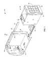
- FIG. 1is a partially cut-away and partially exploded perspective view of a preferred embodiment of the inventive security box.
- FIG. 2is a side view of a drawer portion of the box of FIG. 1 with a side wall removed to show internal components.
- FIG. 3is a cross-sectional view of FIG. 2 , taken along the line 3 - 3 thereof.
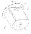
- FIG. 4is an oblique rear perspective view of the box of FIG. 1 with the drawer closed and a trim disk positioned on a front face.
- FIGS. 5-7are fragmentary views of a latching and emergency opening system preferred for the box of FIGS. 1-4 .
- FIG. 8is a perspective view of an alternative preferred embodiment shown without a housing to reveal a different latching system for the box.
- the security box 10 as illustrateduses an openable closure such as a drawer, door, or lid that can open from a housing 50 to afford access to a security asset.
- a drawer 20such as illustrated is convenient for several reasons as a way of accessing contents of box 10 .
- Closure 20contains a security asset such as a key ( FIG. 8 ), but things other than keys can also be secured within box 10 . These can include smart cards, special tools or anything of security importance that can fit within box 10 and deserves the expense of controlled access.
- Access to box 10is controlled by a personal identifier so that only authorized persons can gain access to box 10 .
- One simple way that this can be doneis with number pad 25 that can be conveniently arranged on a front face of closure 20 .
- Biometric devicessuch as thumb or fingerprint readers, eye image readers, and possibly others, can all be used. The basic idea is to restrict access to box 10 to only the person or people who are authorized.
- Box 10preferably uses an access solenoid 30 arranged in box 10 or in drawer 20 to unlatch closure drawer 20 for opening in response to entry of an authorized personal identifier.
- Box 10preferably also has an emergency opening system using an emergency release solenoid 40 that can be arranged in housing 50 .
- a preferred latching system operable with solenoids 30 and 40uses a sliding latch bar 41 having a hole 42 that can be engaged by emergency release solenoid 40 , and having another hole 43 that can be engaged by access solenoid 30 .
- FIGS. 5-7show how the access and the emergency release latching system works.
- the closed positionis illustrated in FIG. 5 with solenoid 30 mounted on closure drawer 20 inside of housing 50 where emergency release solenoid 40 is mounted.
- Each of the solenoidsengage slidable latch bar 41 at holes 42 and 43 .
- access solenoid 30When access solenoid 30 is actuated, its pin retracts from hole 43 so that drawer 20 can open while access solenoid 30 moves with it to the position of FIG. 6 . If access solenoid 30 is disabled, emergency release solenoid 40 can be actuated, as shown in FIG. 7 . This allows sliding latch bar 41 to release and move with access solenoid 30 , allowing closure drawer 20 to open.
- An emergency disabling access solenoid 30is often a power failure, so emergency release solenoid 40 has a different power supply, preferably from a source remote from box 10 .
- Thiscan be as simple as a 12-volt battery connectable to contacts wired to emergency release solenoid 40 at a location some distance away from box 10 .
- FIG. 20Another preferred aspect of the opening of drawer 20 is a push-to-release feature.
- springs 51pushing forward on drawer 20 frictionally holds pin 44 of access solenoid 30 in place within hole 43 of slide bar 41 .
- Pushing back on the front 26 of drawer 20overcomes the spring pressure and allows solenoid pin 44 to release which then allows drawer 20 to move forward under the urging of springs 51 .
- Drawer 20can then be pulled out as far as necessary to reach the security asset that it contains.
- Box 10preferably includes a web server 60 , which is conveniently arranged within closure drawer 20 . This makes it accessible if repairs or replacement become necessary.
- Mother board 61 and other electronicsare preferably also mounted in drawer 20 .
- Power for the electronic components in drawer 20is preferably derived from a power over Ethernet (POE) connection which preferably enters housing 50 via a rear opening 52 from which it can be plugged into a top of receptacle 70 .
- a similar plug 71 on wiring tray 75automatically plugs into receptacle 70 to power drawer components when drawer 20 is moved into a closed position.
- Wiring tray 75then detents into housing 50 by means of a projection 73 entering an opening 74 in wiring tray 75 . This holds wiring tray 75 in place as drawer 20 moves in and out, while a flexible cable 76 conveys power between receptacle 70 and components in moving drawer 20 .
- FIG. 3shows a power over Ethernet
- Housing 50is designed for secure emplacement within a wall or other permanent structure.
- a rear end 55has opening 52 for wiring purposes, and a front face of housing 50 preferably includes a circular trim disk 56 surrounding drawer front 26 . This arrangement allows a circular hole to be drilled in a wall to receive housing 50 with disk 56 fitting tightly over and enclosing the opening.
- Securing housing 50 within a wallcan be done in several ways.
- One preferred wayis to fill a cavity around housing 50 with an adhesive foam material that strongly resists any removal of housing 50 .
- Thiscan be enhanced by fixture blocks 57 , one of which is shown in FIG. 4 .
- Trim disk 56can be secured to fixture block 57 by a screw extending through disk hole 58 and into block 57 .
- Many other arrangements of fasteners, set screws, adhesives, welding, and other expedientscan be used to secure housing 50 solidly in place.
- the front opening 65 of housing 50is preferably stepped and flared slightly outward to receive front perimeter 61 of drawer 20 , as shown in FIG. 1 .
- Front face 26 of drawer 20preferably fits flush with front rim 65 of housing 50 when drawer 20 is closed. This affords no purchase for a pry bar to get a hold of drawer 20 and force it outward.
- their confronting surfacesare preferably covered or coated with a non-stick material such as polytetrafluoroethylene. This helps prevent drawer 20 from freezing shut.
- FIG. 8An alternative box 80 , illustrated in FIG. 8 , is similar to box 10 except for a different latching arrangement. Access solenoid 30 still moves with drawer 20 , and emergency release solenoid 40 is still fixed in housing 50 , the rear plate 55 of which is shown in FIG. 8 . Instead of sliding bar latch 41 , box 80 has a pivoting latch 90 normally engaged and disengaged by access solenoid 30 for opening and closing of drawer 20 . Pin 91 of solenoid 40 holds latch arm 90 in place by passing through latch arm 90 and into fixed bracket 92 , which is secured to rear housing wall 55 . In an emergency, solenoid 40 actuates to retract pin 91 and release latch arm 90 from housing rear plate 55 so that latch arm 90 is free to move with drawer 20 even though access drawer solenoid 30 is disabled.
Landscapes
- Physics & Mathematics (AREA)
- General Physics & Mathematics (AREA)
- Engineering & Computer Science (AREA)
- Computer Networks & Wireless Communication (AREA)
- Signal Processing (AREA)
- Lock And Its Accessories (AREA)
- Drawers Of Furniture (AREA)
Abstract
Description
Claims (24)
Priority Applications (1)
| Application Number | Priority Date | Filing Date | Title |
|---|---|---|---|
| US12/464,370US8704635B2 (en) | 2003-08-19 | 2009-05-12 | Secure web accessed box |
Applications Claiming Priority (4)
| Application Number | Priority Date | Filing Date | Title |
|---|---|---|---|
| US10/644,383US20040153386A1 (en) | 2002-08-19 | 2003-08-19 | Tangible security asset management system and methods thereof |
| US68618105P | 2005-06-01 | 2005-06-01 | |
| US11/421,635US20060288101A1 (en) | 2003-08-19 | 2006-06-01 | Multipurpose Interface and Control System |
| US12/464,370US8704635B2 (en) | 2003-08-19 | 2009-05-12 | Secure web accessed box |
Related Parent Applications (1)
| Application Number | Title | Priority Date | Filing Date |
|---|---|---|---|
| US11/421,635Continuation-In-PartUS20060288101A1 (en) | 2003-08-19 | 2006-06-01 | Multipurpose Interface and Control System |
Publications (2)
| Publication Number | Publication Date |
|---|---|
| US20090237207A1 US20090237207A1 (en) | 2009-09-24 |
| US8704635B2true US8704635B2 (en) | 2014-04-22 |
Family
ID=41088304
Family Applications (1)
| Application Number | Title | Priority Date | Filing Date |
|---|---|---|---|
| US12/464,370Active - Reinstated2027-04-27US8704635B2 (en) | 2003-08-19 | 2009-05-12 | Secure web accessed box |
Country Status (1)
| Country | Link |
|---|---|
| US (1) | US8704635B2 (en) |
Citations (17)
| Publication number | Priority date | Publication date | Assignee | Title |
|---|---|---|---|---|
| US3761682A (en)* | 1971-10-07 | 1973-09-25 | Docutel Corp | Credit card automatic currency dispenser |
| US4750197A (en)* | 1986-11-10 | 1988-06-07 | Denekamp Mark L | Integrated cargo security system |
| US5244020A (en)* | 1991-07-24 | 1993-09-14 | Middleby Marshall Inc. | Dispenser |
| US5392025A (en)* | 1993-09-24 | 1995-02-21 | Intermark Corporation | Electronic security system for display cabinets |
| US5887468A (en) | 1994-03-22 | 1999-03-30 | Hasan; Noam | Assembly for retaining of keys or similar objects |
| US6428060B1 (en) | 2000-01-03 | 2002-08-06 | Norco, Inc. | Latch mechanism |
| US6434985B1 (en) | 2001-05-30 | 2002-08-20 | Exodus Innovations Pty Limited | Security grille locking system |
| US20030034390A1 (en)* | 2000-10-20 | 2003-02-20 | Linton William A. | Radio frequency identification method and system of distributing products |
| US6564121B1 (en) | 1999-09-22 | 2003-05-13 | Telepharmacy Solutions, Inc. | Systems and methods for drug dispensing |
| US20030183136A1 (en)* | 2001-12-19 | 2003-10-02 | Perkins Daniel D. | Hidden drawer safe |
| US6675067B2 (en) | 2000-03-09 | 2004-01-06 | Steven J. Blad | Computer network based coin-operated machine monitoring system |
| US20040051626A1 (en)* | 2002-09-18 | 2004-03-18 | David Pautler | System and method for providing access from a remote location |
| US20040075533A1 (en)* | 2000-09-26 | 2004-04-22 | Ives Thomas W. | Methods and apparatus for verifying the installation of components in a system |
| US20040252018A1 (en)* | 2000-07-11 | 2004-12-16 | Shuster Gary Stephen | Electronically controlled lockbox |
| US20050145740A1 (en)* | 2002-01-11 | 2005-07-07 | Siemens Aktiengesellschaft | Method for actuating a pawl in a lock with a rotary latch for a motor vehicle |
| US20050165612A1 (en)* | 2000-04-19 | 2005-07-28 | Van Rysselberghe Pierre C. | Security systems for delivering goods and services |
| US7323991B1 (en)* | 2005-05-12 | 2008-01-29 | Exavera Technologies Incorporated | System and method for locating and communicating with personnel and equipment in a facility |
- 2009
- 2009-05-12USUS12/464,370patent/US8704635B2/enactiveActive - Reinstated
Patent Citations (17)
| Publication number | Priority date | Publication date | Assignee | Title |
|---|---|---|---|---|
| US3761682A (en)* | 1971-10-07 | 1973-09-25 | Docutel Corp | Credit card automatic currency dispenser |
| US4750197A (en)* | 1986-11-10 | 1988-06-07 | Denekamp Mark L | Integrated cargo security system |
| US5244020A (en)* | 1991-07-24 | 1993-09-14 | Middleby Marshall Inc. | Dispenser |
| US5392025A (en)* | 1993-09-24 | 1995-02-21 | Intermark Corporation | Electronic security system for display cabinets |
| US5887468A (en) | 1994-03-22 | 1999-03-30 | Hasan; Noam | Assembly for retaining of keys or similar objects |
| US6564121B1 (en) | 1999-09-22 | 2003-05-13 | Telepharmacy Solutions, Inc. | Systems and methods for drug dispensing |
| US6428060B1 (en) | 2000-01-03 | 2002-08-06 | Norco, Inc. | Latch mechanism |
| US6675067B2 (en) | 2000-03-09 | 2004-01-06 | Steven J. Blad | Computer network based coin-operated machine monitoring system |
| US20050165612A1 (en)* | 2000-04-19 | 2005-07-28 | Van Rysselberghe Pierre C. | Security systems for delivering goods and services |
| US20040252018A1 (en)* | 2000-07-11 | 2004-12-16 | Shuster Gary Stephen | Electronically controlled lockbox |
| US20040075533A1 (en)* | 2000-09-26 | 2004-04-22 | Ives Thomas W. | Methods and apparatus for verifying the installation of components in a system |
| US20030034390A1 (en)* | 2000-10-20 | 2003-02-20 | Linton William A. | Radio frequency identification method and system of distributing products |
| US6434985B1 (en) | 2001-05-30 | 2002-08-20 | Exodus Innovations Pty Limited | Security grille locking system |
| US20030183136A1 (en)* | 2001-12-19 | 2003-10-02 | Perkins Daniel D. | Hidden drawer safe |
| US20050145740A1 (en)* | 2002-01-11 | 2005-07-07 | Siemens Aktiengesellschaft | Method for actuating a pawl in a lock with a rotary latch for a motor vehicle |
| US20040051626A1 (en)* | 2002-09-18 | 2004-03-18 | David Pautler | System and method for providing access from a remote location |
| US7323991B1 (en)* | 2005-05-12 | 2008-01-29 | Exavera Technologies Incorporated | System and method for locating and communicating with personnel and equipment in a facility |
Also Published As
| Publication number | Publication date |
|---|---|
| US20090237207A1 (en) | 2009-09-24 |
Similar Documents
| Publication | Publication Date | Title |
|---|---|---|
| US10362889B2 (en) | Receptacle for receiving and securing packages and other items | |
| US5550529A (en) | Access control system | |
| US6564600B1 (en) | Electronic access control device | |
| US7698917B2 (en) | Electronic deadbolt lock with a leverage handle | |
| US4749359A (en) | Security override network interface device | |
| US20040129043A1 (en) | Computer network equipment enclosure having exchangeable securing mechanisms | |
| US5325685A (en) | Portable auxiliary door lock | |
| US20170186258A1 (en) | Electronic locker | |
| WO1998021117A1 (en) | Access control system for security enclosure | |
| US7152802B2 (en) | Storing and accessing keys | |
| US20020067046A1 (en) | Drop lock-outward opening door retaining device | |
| CN101654994A (en) | Intelligent fingerprint security door | |
| AU2011257943B2 (en) | A power source and/or control component housing primarily for door mounted devices | |
| CN205955426U (en) | Be applied to electric control lock of hanging instructional terminal | |
| US8704635B2 (en) | Secure web accessed box | |
| US2802685A (en) | Convertible lock for sliding doors | |
| US20060071483A1 (en) | Device for latching a cabinet door | |
| DK200500078U3 (en) | Lockbox for locked storage of coded access items - such as access cards and nails | |
| US6454579B1 (en) | Computerized plug lock | |
| GB2407615A (en) | Security chain with mechanical lock and manual release | |
| KR102155984B1 (en) | A door device | |
| JP2006249889A (en) | Key storing device | |
| US7057885B2 (en) | Locking mechanism for a personal computer | |
| JP6137889B2 (en) | Handle with lock | |
| US20160230443A1 (en) | Surface Mountable Security Asset Storage Container |
Legal Events
| Date | Code | Title | Description |
|---|---|---|---|
| AS | Assignment | Owner name:KEY SYSTEMS, INC., NEW YORK Free format text:ASSIGNMENT OF ASSIGNORS INTEREST;ASSIGNORS:ECKERDT, GEORGE H;MASTRODONATO, GEORGE;REEL/FRAME:022671/0662 Effective date:20090505 | |
| FEPP | Fee payment procedure | Free format text:PAYOR NUMBER ASSIGNED (ORIGINAL EVENT CODE: ASPN); ENTITY STATUS OF PATENT OWNER: SMALL ENTITY | |
| FEPP | Fee payment procedure | Free format text:MAINTENANCE FEE REMINDER MAILED (ORIGINAL EVENT CODE: REM.) | |
| LAPS | Lapse for failure to pay maintenance fees | Free format text:PATENT EXPIRED FOR FAILURE TO PAY MAINTENANCE FEES (ORIGINAL EVENT CODE: EXP.) | |
| FP | Lapsed due to failure to pay maintenance fee | Effective date:20180422 | |
| PRDP | Patent reinstated due to the acceptance of a late maintenance fee | Effective date:20180622 | |
| FEPP | Fee payment procedure | Free format text:SURCHARGE, PETITION TO ACCEPT PYMT AFTER EXP, UNINTENTIONAL. (ORIGINAL EVENT CODE: M2558); ENTITY STATUS OF PATENT OWNER: SMALL ENTITY Free format text:PETITION RELATED TO MAINTENANCE FEES GRANTED (ORIGINAL EVENT CODE: PMFG) Free format text:PETITION RELATED TO MAINTENANCE FEES FILED (ORIGINAL EVENT CODE: PMFP) | |
| MAFP | Maintenance fee payment | Free format text:PAYMENT OF MAINTENANCE FEE, 4TH YR, SMALL ENTITY (ORIGINAL EVENT CODE: M2551) Year of fee payment:4 | |
| STCF | Information on status: patent grant | Free format text:PATENTED CASE | |
| FEPP | Fee payment procedure | Free format text:MAINTENANCE FEE REMINDER MAILED (ORIGINAL EVENT CODE: REM.); ENTITY STATUS OF PATENT OWNER: SMALL ENTITY | |
| FEPP | Fee payment procedure | Free format text:7.5 YR SURCHARGE - LATE PMT W/IN 6 MO, SMALL ENTITY (ORIGINAL EVENT CODE: M2555); ENTITY STATUS OF PATENT OWNER: SMALL ENTITY | |
| MAFP | Maintenance fee payment | Free format text:PAYMENT OF MAINTENANCE FEE, 8TH YR, SMALL ENTITY (ORIGINAL EVENT CODE: M2552); ENTITY STATUS OF PATENT OWNER: SMALL ENTITY Year of fee payment:8 |