US8704380B2 - Methods for wafer-level packaging of microfeature devices and microfeature devices formed using such methods - Google Patents
Methods for wafer-level packaging of microfeature devices and microfeature devices formed using such methodsDownload PDFInfo
- Publication number
- US8704380B2 US8704380B2US12/874,644US87464410AUS8704380B2US 8704380 B2US8704380 B2US 8704380B2US 87464410 AUS87464410 AUS 87464410AUS 8704380 B2US8704380 B2US 8704380B2
- Authority
- US
- United States
- Prior art keywords
- dies
- integrated circuitry
- assembly
- support member
- electrically coupled
- Prior art date
- Legal status (The legal status is an assumption and is not a legal conclusion. Google has not performed a legal analysis and makes no representation as to the accuracy of the status listed.)
- Active, expires
Links
Images


Classifications
- H—ELECTRICITY
- H01—ELECTRIC ELEMENTS
- H01L—SEMICONDUCTOR DEVICES NOT COVERED BY CLASS H10
- H01L21/00—Processes or apparatus adapted for the manufacture or treatment of semiconductor or solid state devices or of parts thereof
- H01L21/67—Apparatus specially adapted for handling semiconductor or electric solid state devices during manufacture or treatment thereof; Apparatus specially adapted for handling wafers during manufacture or treatment of semiconductor or electric solid state devices or components ; Apparatus not specifically provided for elsewhere
- H01L21/683—Apparatus specially adapted for handling semiconductor or electric solid state devices during manufacture or treatment thereof; Apparatus specially adapted for handling wafers during manufacture or treatment of semiconductor or electric solid state devices or components ; Apparatus not specifically provided for elsewhere for supporting or gripping
- H01L21/6835—Apparatus specially adapted for handling semiconductor or electric solid state devices during manufacture or treatment thereof; Apparatus specially adapted for handling wafers during manufacture or treatment of semiconductor or electric solid state devices or components ; Apparatus not specifically provided for elsewhere for supporting or gripping using temporarily an auxiliary support
- H—ELECTRICITY
- H01—ELECTRIC ELEMENTS
- H01L—SEMICONDUCTOR DEVICES NOT COVERED BY CLASS H10
- H01L21/00—Processes or apparatus adapted for the manufacture or treatment of semiconductor or solid state devices or of parts thereof
- H01L21/02—Manufacture or treatment of semiconductor devices or of parts thereof
- H01L21/04—Manufacture or treatment of semiconductor devices or of parts thereof the devices having potential barriers, e.g. a PN junction, depletion layer or carrier concentration layer
- H01L21/50—Assembly of semiconductor devices using processes or apparatus not provided for in a single one of the groups H01L21/18 - H01L21/326 or H10D48/04 - H10D48/07 e.g. sealing of a cap to a base of a container
- H01L21/56—Encapsulations, e.g. encapsulation layers, coatings
- H01L21/568—Temporary substrate used as encapsulation process aid
- H—ELECTRICITY
- H01—ELECTRIC ELEMENTS
- H01L—SEMICONDUCTOR DEVICES NOT COVERED BY CLASS H10
- H01L24/00—Arrangements for connecting or disconnecting semiconductor or solid-state bodies; Methods or apparatus related thereto
- H01L24/93—Batch processes
- H01L24/95—Batch processes at chip-level, i.e. with connecting carried out on a plurality of singulated devices, i.e. on diced chips
- H01L24/96—Batch processes at chip-level, i.e. with connecting carried out on a plurality of singulated devices, i.e. on diced chips the devices being encapsulated in a common layer, e.g. neo-wafer or pseudo-wafer, said common layer being separable into individual assemblies after connecting
- H—ELECTRICITY
- H01—ELECTRIC ELEMENTS
- H01L—SEMICONDUCTOR DEVICES NOT COVERED BY CLASS H10
- H01L24/00—Arrangements for connecting or disconnecting semiconductor or solid-state bodies; Methods or apparatus related thereto
- H01L24/93—Batch processes
- H01L24/95—Batch processes at chip-level, i.e. with connecting carried out on a plurality of singulated devices, i.e. on diced chips
- H01L24/97—Batch processes at chip-level, i.e. with connecting carried out on a plurality of singulated devices, i.e. on diced chips the devices being connected to a common substrate, e.g. interposer, said common substrate being separable into individual assemblies after connecting
- H—ELECTRICITY
- H01—ELECTRIC ELEMENTS
- H01L—SEMICONDUCTOR DEVICES NOT COVERED BY CLASS H10
- H01L25/00—Assemblies consisting of a plurality of semiconductor or other solid state devices
- H01L25/03—Assemblies consisting of a plurality of semiconductor or other solid state devices all the devices being of a type provided for in a single subclass of subclasses H10B, H10D, H10F, H10H, H10K or H10N, e.g. assemblies of rectifier diodes
- H01L25/04—Assemblies consisting of a plurality of semiconductor or other solid state devices all the devices being of a type provided for in a single subclass of subclasses H10B, H10D, H10F, H10H, H10K or H10N, e.g. assemblies of rectifier diodes the devices not having separate containers
- H01L25/065—Assemblies consisting of a plurality of semiconductor or other solid state devices all the devices being of a type provided for in a single subclass of subclasses H10B, H10D, H10F, H10H, H10K or H10N, e.g. assemblies of rectifier diodes the devices not having separate containers the devices being of a type provided for in group H10D89/00
- H01L25/0652—Assemblies consisting of a plurality of semiconductor or other solid state devices all the devices being of a type provided for in a single subclass of subclasses H10B, H10D, H10F, H10H, H10K or H10N, e.g. assemblies of rectifier diodes the devices not having separate containers the devices being of a type provided for in group H10D89/00 the devices being arranged next and on each other, i.e. mixed assemblies
- H—ELECTRICITY
- H01—ELECTRIC ELEMENTS
- H01L—SEMICONDUCTOR DEVICES NOT COVERED BY CLASS H10
- H01L25/00—Assemblies consisting of a plurality of semiconductor or other solid state devices
- H01L25/03—Assemblies consisting of a plurality of semiconductor or other solid state devices all the devices being of a type provided for in a single subclass of subclasses H10B, H10D, H10F, H10H, H10K or H10N, e.g. assemblies of rectifier diodes
- H01L25/04—Assemblies consisting of a plurality of semiconductor or other solid state devices all the devices being of a type provided for in a single subclass of subclasses H10B, H10D, H10F, H10H, H10K or H10N, e.g. assemblies of rectifier diodes the devices not having separate containers
- H01L25/065—Assemblies consisting of a plurality of semiconductor or other solid state devices all the devices being of a type provided for in a single subclass of subclasses H10B, H10D, H10F, H10H, H10K or H10N, e.g. assemblies of rectifier diodes the devices not having separate containers the devices being of a type provided for in group H10D89/00
- H01L25/0657—Stacked arrangements of devices
- H—ELECTRICITY
- H01—ELECTRIC ELEMENTS
- H01L—SEMICONDUCTOR DEVICES NOT COVERED BY CLASS H10
- H01L25/00—Assemblies consisting of a plurality of semiconductor or other solid state devices
- H01L25/50—Multistep manufacturing processes of assemblies consisting of devices, the devices being individual devices of subclass H10D or integrated devices of class H10
- H—ELECTRICITY
- H01—ELECTRIC ELEMENTS
- H01L—SEMICONDUCTOR DEVICES NOT COVERED BY CLASS H10
- H01L2224/00—Indexing scheme for arrangements for connecting or disconnecting semiconductor or solid-state bodies and methods related thereto as covered by H01L24/00
- H01L2224/01—Means for bonding being attached to, or being formed on, the surface to be connected, e.g. chip-to-package, die-attach, "first-level" interconnects; Manufacturing methods related thereto
- H01L2224/02—Bonding areas; Manufacturing methods related thereto
- H01L2224/04—Structure, shape, material or disposition of the bonding areas prior to the connecting process
- H01L2224/04105—Bonding areas formed on an encapsulation of the semiconductor or solid-state body, e.g. bonding areas on chip-scale packages
- H—ELECTRICITY
- H01—ELECTRIC ELEMENTS
- H01L—SEMICONDUCTOR DEVICES NOT COVERED BY CLASS H10
- H01L2224/00—Indexing scheme for arrangements for connecting or disconnecting semiconductor or solid-state bodies and methods related thereto as covered by H01L24/00
- H01L2224/01—Means for bonding being attached to, or being formed on, the surface to be connected, e.g. chip-to-package, die-attach, "first-level" interconnects; Manufacturing methods related thereto
- H01L2224/10—Bump connectors; Manufacturing methods related thereto
- H01L2224/12—Structure, shape, material or disposition of the bump connectors prior to the connecting process
- H01L2224/12105—Bump connectors formed on an encapsulation of the semiconductor or solid-state body, e.g. bumps on chip-scale packages
- H—ELECTRICITY
- H01—ELECTRIC ELEMENTS
- H01L—SEMICONDUCTOR DEVICES NOT COVERED BY CLASS H10
- H01L2224/00—Indexing scheme for arrangements for connecting or disconnecting semiconductor or solid-state bodies and methods related thereto as covered by H01L24/00
- H01L2224/01—Means for bonding being attached to, or being formed on, the surface to be connected, e.g. chip-to-package, die-attach, "first-level" interconnects; Manufacturing methods related thereto
- H01L2224/10—Bump connectors; Manufacturing methods related thereto
- H01L2224/15—Structure, shape, material or disposition of the bump connectors after the connecting process
- H01L2224/16—Structure, shape, material or disposition of the bump connectors after the connecting process of an individual bump connector
- H01L2224/161—Disposition
- H01L2224/16135—Disposition the bump connector connecting between different semiconductor or solid-state bodies, i.e. chip-to-chip
- H01L2224/16145—Disposition the bump connector connecting between different semiconductor or solid-state bodies, i.e. chip-to-chip the bodies being stacked
- H—ELECTRICITY
- H01—ELECTRIC ELEMENTS
- H01L—SEMICONDUCTOR DEVICES NOT COVERED BY CLASS H10
- H01L2224/00—Indexing scheme for arrangements for connecting or disconnecting semiconductor or solid-state bodies and methods related thereto as covered by H01L24/00
- H01L2224/73—Means for bonding being of different types provided for in two or more of groups H01L2224/10, H01L2224/18, H01L2224/26, H01L2224/34, H01L2224/42, H01L2224/50, H01L2224/63, H01L2224/71
- H01L2224/732—Location after the connecting process
- H01L2224/73251—Location after the connecting process on different surfaces
- H01L2224/73259—Bump and HDI connectors
- H—ELECTRICITY
- H01—ELECTRIC ELEMENTS
- H01L—SEMICONDUCTOR DEVICES NOT COVERED BY CLASS H10
- H01L2224/00—Indexing scheme for arrangements for connecting or disconnecting semiconductor or solid-state bodies and methods related thereto as covered by H01L24/00
- H01L2224/80—Methods for connecting semiconductor or other solid state bodies using means for bonding being attached to, or being formed on, the surface to be connected
- H01L2224/81—Methods for connecting semiconductor or other solid state bodies using means for bonding being attached to, or being formed on, the surface to be connected using a bump connector
- H01L2224/81001—Methods for connecting semiconductor or other solid state bodies using means for bonding being attached to, or being formed on, the surface to be connected using a bump connector involving a temporary auxiliary member not forming part of the bonding apparatus
- H01L2224/81005—Methods for connecting semiconductor or other solid state bodies using means for bonding being attached to, or being formed on, the surface to be connected using a bump connector involving a temporary auxiliary member not forming part of the bonding apparatus being a temporary or sacrificial substrate
- H—ELECTRICITY
- H01—ELECTRIC ELEMENTS
- H01L—SEMICONDUCTOR DEVICES NOT COVERED BY CLASS H10
- H01L2225/00—Details relating to assemblies covered by the group H01L25/00 but not provided for in its subgroups
- H01L2225/03—All the devices being of a type provided for in the same main group of the same subclass of class H10, e.g. assemblies of rectifier diodes
- H01L2225/04—All the devices being of a type provided for in the same main group of the same subclass of class H10, e.g. assemblies of rectifier diodes the devices not having separate containers
- H01L2225/065—All the devices being of a type provided for in the same main group of the same subclass of class H10
- H01L2225/06503—Stacked arrangements of devices
- H01L2225/06513—Bump or bump-like direct electrical connections between devices, e.g. flip-chip connection, solder bumps
- H—ELECTRICITY
- H01—ELECTRIC ELEMENTS
- H01L—SEMICONDUCTOR DEVICES NOT COVERED BY CLASS H10
- H01L2225/00—Details relating to assemblies covered by the group H01L25/00 but not provided for in its subgroups
- H01L2225/03—All the devices being of a type provided for in the same main group of the same subclass of class H10, e.g. assemblies of rectifier diodes
- H01L2225/04—All the devices being of a type provided for in the same main group of the same subclass of class H10, e.g. assemblies of rectifier diodes the devices not having separate containers
- H01L2225/065—All the devices being of a type provided for in the same main group of the same subclass of class H10
- H01L2225/06503—Stacked arrangements of devices
- H01L2225/06582—Housing for the assembly, e.g. chip scale package [CSP]
- H01L2225/06586—Housing with external bump or bump-like connectors
- H—ELECTRICITY
- H01—ELECTRIC ELEMENTS
- H01L—SEMICONDUCTOR DEVICES NOT COVERED BY CLASS H10
- H01L2924/00—Indexing scheme for arrangements or methods for connecting or disconnecting semiconductor or solid-state bodies as covered by H01L24/00
- H01L2924/01—Chemical elements
- H01L2924/01005—Boron [B]
- H—ELECTRICITY
- H01—ELECTRIC ELEMENTS
- H01L—SEMICONDUCTOR DEVICES NOT COVERED BY CLASS H10
- H01L2924/00—Indexing scheme for arrangements or methods for connecting or disconnecting semiconductor or solid-state bodies as covered by H01L24/00
- H01L2924/01—Chemical elements
- H01L2924/01006—Carbon [C]
- H—ELECTRICITY
- H01—ELECTRIC ELEMENTS
- H01L—SEMICONDUCTOR DEVICES NOT COVERED BY CLASS H10
- H01L2924/00—Indexing scheme for arrangements or methods for connecting or disconnecting semiconductor or solid-state bodies as covered by H01L24/00
- H01L2924/01—Chemical elements
- H01L2924/01033—Arsenic [As]
- H—ELECTRICITY
- H01—ELECTRIC ELEMENTS
- H01L—SEMICONDUCTOR DEVICES NOT COVERED BY CLASS H10
- H01L2924/00—Indexing scheme for arrangements or methods for connecting or disconnecting semiconductor or solid-state bodies as covered by H01L24/00
- H01L2924/01—Chemical elements
- H01L2924/01082—Lead [Pb]
- H—ELECTRICITY
- H01—ELECTRIC ELEMENTS
- H01L—SEMICONDUCTOR DEVICES NOT COVERED BY CLASS H10
- H01L2924/00—Indexing scheme for arrangements or methods for connecting or disconnecting semiconductor or solid-state bodies as covered by H01L24/00
- H01L2924/10—Details of semiconductor or other solid state devices to be connected
- H01L2924/11—Device type
- H01L2924/14—Integrated circuits
- H—ELECTRICITY
- H01—ELECTRIC ELEMENTS
- H01L—SEMICONDUCTOR DEVICES NOT COVERED BY CLASS H10
- H01L2924/00—Indexing scheme for arrangements or methods for connecting or disconnecting semiconductor or solid-state bodies as covered by H01L24/00
- H01L2924/15—Details of package parts other than the semiconductor or other solid state devices to be connected
- H01L2924/181—Encapsulation
- H01L2924/1815—Shape
- H01L2924/1816—Exposing the passive side of the semiconductor or solid-state body
- H01L2924/18161—Exposing the passive side of the semiconductor or solid-state body of a flip chip
Definitions
- the present inventionis related to methods for wafer-level packaging of microfeature devices and microfeature devices formed using such methods.
- Conventional packaged microelectronic devicescan include a singulated microelectronic die, an interposer substrate or lead frame attached to the die, and a molded casing around the die.
- the diegenerally includes an integrated circuit and a plurality of bond-pads coupled to the integrated circuit.
- the bond-padsare typically coupled to terminals on the interposer substrate or lead frame, and supply voltage, signals, etc., are transmitted to and from the integrated circuit via the bond-pads.
- the interposer substratecan also include ball-pads coupled to the terminals by conductive traces supported in a dielectric material.
- Solder ballscan be attached to the ball-pads in one-to-one correspondence to define a “ball-grid array.”
- Packaged microelectronic devices with ball-grid arraysare generally higher grade packages having lower profiles and higher pin counts than conventional packages using lead frames.
- Packaged microelectronic devicessuch as those described above are used in cellular phones, pagers, personal digital assistants, computers, and many other electronic products. To meet the demand for smaller electronic products, there is a continuing drive to increase the performance of packaged microelectronic devices, while at the same time reducing the height and the surface area or “footprint” of such devices on printed circuit boards. Reducing the size of high performance devices, however, is difficult because the sophisticated integrated circuitry requires more bond-pads, which results in larger ball-grid arrays and thus larger footprints.
- One technique for increasing the component density of microelectronic devices within a given footprintis to stack one device on top of another.
- One conventional stacking processincludes placing a plurality of singulated first dies in a fixture and stacking a plurality of singulated second dies onto corresponding first dies.
- the stacked first and second diescan then be heated to reflow solder bumps on the second dies and securely attach the second dies to corresponding first dies.
- the stacked assemblies of first and second diesare then taken out of the fixture and mounted on an interposer substrate (e.g., in a “flip-chip” arrangement).
- Another reflow processcan be used to securely attach the individual stacked die assemblies to the interposer substrate.
- the stacked die assemblies on the interposer substratecan then be encapsulated and singulated.
- the conventional stacking process described abovehas several drawbacks.
- the processincludes a large number of steps and accordingly can be relatively expensive.
- the large number of stepscan also reduce the throughput of finished devices.
- Another drawback of the conventional process described aboveis that the stacked die assemblies can have a relatively large footprint and occupy a significant amount of vertical space (i.e., high profile) because the dies are stacked on an interposer substrate.
- Another conventional stacking processincludes forming a plurality of first dies on a first support member (e.g., a film frame) and a plurality of second dies on a second support member (e.g., a film frame).
- the individual first and second diescan be tested while on the support members with a probe device. After testing, the first and second dies are singulated and mounted directly onto an interposer substrate in a stacked configuration.
- This stacking processalso includes several drawbacks. For example, although the dies are tested before singulation to ensure that they function properly, the dies must still undergo a variety of fabrication and packaging processes (e.g., singulation, bumping, mounting) after testing. If the dies become inoperable and/or damaged after these rigorous packaging processes, the entire packaged device (rather than just the bad die) is generally discarded. Accordingly, there is a need to improve the processes for packaging microfeature devices.
- FIGS. 1A-1Fillustrate stages in a method for wafer-level packaging of microfeature devices in accordance with an embodiment of the invention.
- FIGS. 2A-2Dillustrate stages in a method for wafer-level packaging of microfeature devices in accordance with another embodiment of the invention.
- FIGS. 3A and 3Billustrate stages in a method for wafer-level packaging of microfeature devices in accordance with still another embodiment of the invention.
- FIGS. 4A and 4Billustrate stages in a method for wafer-level packaging of microfeature devices in accordance with yet another embodiment of the invention.
- FIGS. 5A-5Cillustrate stages in a method for wafer-level packaging of microfeature devices in accordance with another embodiment of the invention.
- the following disclosuredescribes methods for wafer-level packaging of microfeature devices and microfeature devices formed using such methods.
- One aspect of the inventionis directed toward a method for packaging microfeature devices.
- the methodcan include releasably attaching a plurality of first known good microelectronic dies to a carrier substrate in a desired arrangement.
- the first diescan be releasably attached to an attachment feature on the carrier substrate.
- the methodcan also include attaching one or more second known good microelectronic dies to the individual first dies in a stacked configuration to form a plurality of stacked devices.
- the methodfurther includes at least partially encapsulating the stacked devices and separating the stacked devices from each other.
- the methodcan further include (a) removing the carrier substrate after encapsulation and before separating the stacked devices from each other, and (b) attaching a plurality of electrical couplers to external contacts on the first dies after removing the carrier substrate and before separating the stacked devices.
- the first and second diescan include a variety of configurations and orientations with respect to each other and/or the carrier substrate.
- the first diescan include memory devices, processors, or other types of devices that include integrated circuitry.
- the second diescan include devices generally similar to the first dies, as well as devices including image sensors and optical elements formed on the dies over the image sensors.
- the first diescan be releasably attached to the carrier substrate with an active side or a back side of the first dies adjacent the carrier substrate, and the second dies can have several different orientations relative to corresponding second dies.
- the first dies and/or second diesmay also include a redistribution layer.
- Another embodiment of a method for packaging microfeature devicesincludes releasably attaching a plurality of first known good microelectronic dies to a carrier substrate in a desired arrangement such that the carrier substrate is substantially populated with the first dies.
- the methodalso includes attaching and electrically coupling second known good microelectronic dies to the individual first dies.
- the second diesare attached to the first dies in a stacked configuration to form a plurality of stacked units.
- the methodalso includes disposing an encapsulant between the stacked units.
- the carrier substrateis removed from the stacked units after disposing the encapsulant between the stacked units.
- the methodthen includes cutting the encapsulant to separate the stacked units from each other.
- Still another embodiment of the inventionis directed to a method for manufacturing microfeature devices including first known good microelectronic dies and second known good microelectronic dies.
- the first dies and second diesinclude integrated circuitry and terminals electrically coupled to the integrated circuitry.
- the methodincludes populating a support member with a plurality of first dies such that the support member is substantially populated with the first dies.
- the methodalso includes coupling second dies to the individual first dies in a stacked configuration.
- the methodcontinues by depositing an encapsulant onto the support member to at least partially encapsulate the first dies and the second dies.
- the methodfurther includes removing the first dies from the support member after at least partially encapsulating the first dies and the second dies and cutting the encapsulant to separate the first dies.
- Additional embodiments of the inventionare directed toward a microfeature assembly including a carrier substrate and a plurality of first known good microelectronic dies releasably attached to the carrier substrate in a desired arrangement.
- the assemblycan also include a plurality of second known good microelectronic dies attached to corresponding first dies in a stacked configuration.
- the assemblyalso includes an encapsulant at least partially encapsulating the first dies and the second dies.
- microfeature assemblyand “microfeature subassembly” are used throughout to include a variety of articles of manufacture, including, e.g., semiconductor wafers having active components, individual integrated circuit dies, packaged dies, and subassemblies comprising two or more microfeature workpieces or components, e.g., a stacked die package.
- semiconductor wafershaving active components
- individual integrated circuit diespackaged dies
- subassembliescomprising two or more microfeature workpieces or components, e.g., a stacked die package.
- FIGS. 1A-1Fillustrate stages in a method for wafer-level packaging of microfeature devices and microfeature devices formed using such a method.
- FIG. 1Ais a top plan view of a support member 100 (e.g., a carrier substrate) at an initial stage in which the support member 100 is being populated with a plurality of first known good microelectronic dies 120
- FIG. 1Bis a side cross-sectional view taken substantially along line 1 B- 1 B of FIG. 1A .
- the support member 100includes a first side 102 , a second side 104 facing opposite the first side 102 , and an attachment feature 106 at the first side 102 .
- the support member 100can have a form factor (e.g., a shape and thickness) suitable for use in semiconductor processing equipment used for subsequent processing of the first dies 120 and second dies ( FIG. 1C ).
- the support member 100has a form factor that is the same as the wafers so that wafer processing equipment can be used for further processing.
- the support member 100can be patterned before being populated with the first dies 120 .
- Patterningcan provide for accurate placement of the first dies 120 on the support member 100 in a predetermined arrangement.
- the patterncan have generally the same arrangement as a typical wafer array, or in other embodiments the pattern can provide for additional spacing between the first dies 120 attached to the support member 100 .
- the first dies 120are spaced apart from each other by gaps 108 that provide sufficient room for encapsulation of the individual first dies 120 and provide adequate tolerances for further processing (e.g., attaching electrical couplers, forming redistribution layers, constructing optical structures, etc.).
- gaps 108are commonly aligned with one another to facilitate cutting with a wafer saw along lanes similar to streets or scribe lines between the individual first dies 120 .
- the support member 100may not be patterned before releasably attaching the first dies 120 to the support member 100 .
- the first dies 120are releasably attached to the attachment feature 106 on the support member 100 during the repopulation process.
- the attachment feature 106can include an adhesive film, epoxy, tape, paste, or other suitable material that releasably secures the first dies 120 in place during processing and has suitable release characteristics for removing the first dies 120 from the support member 100 in subsequent processing steps.
- Suitable materials for the attachment feature 106can include REVALPHA thermal release tape, commercially available from Nitto Denko America of Fremont, Calif.
- the first dies 120(and the second dies described below with respect to FIG. 1C ) can be individually tested and burned-in to ensure that they function properly before being attached to the support member 100 so that only known good dies populate the support member 100 .
- the individual first dies 120can include an active side 122 , a back side 124 , integrated circuitry 125 (shown schematically), a plurality of terminals 126 (e.g., bond-pads) at the active side 122 , and a plurality of pads 128 (only one is shown on each die) at the back side 124 .
- the individual first dies 120also include a redistribution layer 130 (shown in broken lines) at the active side 122 and in contact with the attachment feature 106 on the support member 100 . In other embodiments, however, the individual first dies 120 may not include a redistribution layer 130 .
- the first dies 120can include memory devices, processors, or other types of devices that include integrated circuitry. Although the illustrated first dies 120 have the same configuration, in other embodiments the individual first dies 120 may have different features to perform different functions.
- the first dies 120have been thinned to a thickness T 1 before attachment to the support member 100 . In other embodiments, however, the first dies 120 may not be thinned (as shown in broken lines) before being attached to the support member 100 . In embodiments where the first dies 120 are not pre-thinned, for example, the first dies 120 can be thinned after attachment to the support member 100 from a thickness T 2 to the desired thickness (e.g., thickness T 1 ) using a suitable back grinding process in which the support member 100 is mounted in a grinding machine.
- one or more second known good microelectronic dies 140are stacked on corresponding first dies 120 to form individual stacked microfeature subassemblies 150 (e.g., stacked devices or stacked units).
- the individual second dies 140include integrated circuitry 142 (shown schematically) and a plurality of terminals 144 (only one is shown on each die) electrically coupled to the integrated circuitry 142 .
- the second dies 140can be attached to corresponding first dies 120 by placing the terminals 144 on the second dies 140 in contact with corresponding pads 128 at the back side 124 of the first dies 120 and using a reflow process to electrically and physically couple the second dies 140 to corresponding first dies 120 .
- the second dies 140can be individually tested and burned-in to ensure that they function properly before being stacked on corresponding first dies 120 .
- an encapsulant 160is deposited onto the support member 100 to at least partially encapsulate the stacked subassemblies 150 on the support member 100 .
- the encapsulant 160can be deposited onto the support member 100 using a suitable application process, such as a film-assisted molding process or a glob-type dispensing process.
- a suitable application processsuch as a film-assisted molding process or a glob-type dispensing process.
- the first dies 120are already thinned and, accordingly, a film-assisted molding process may be desirable because the encapsulant 160 will not cover a top surface 152 of the subassemblies 150 (i.e., the top surface of the second dies 140 ).
- the glob-type dispensing processmay be desirable because it can be easier to deposit the encapsulant 160 in the gaps 108 ( FIG. 1A ) between the subassemblies 150 and any residual portions of the encapsulant 160 that remain on the top surface 152 of the subassemblies 150 can be removed during the thinning process.
- other methodscan be used to encapsulate the subassemblies 150 .
- the support member 100( FIG. 1D ) is removed from the encapsulated subassemblies 150 ( FIG. 1D ) to form a plurality of stacked microfeature devices 170 .
- the microfeature devices 170can be inverted so that the active sides 122 of the individual first dies 120 project upwardly (as shown in FIG. 1E ) and a plurality of electrical couplers 180 (e.g., solder balls) can be attached to corresponding contacts on the first dies 120 . After attaching the electrical couplers 180 , the assembly can be cut along lines A-A to singulate the microfeature devices 170 .
- FIG. 1Fis a side cross-sectional view of a stacked microfeature device 170 formed using the methods described above.
- One feature of the microfeature device 170is that both the first die 120 and the second die 140 can be tested to ensure that they function properly before being assembled together.
- An advantage of this featureis that each of the microfeature devices 170 formed using the methods described above includes only known good dies. Defective dies can be detected and excluded from the assembly before fully populating the support member 100 . Throughput of microfeature devices 170 can accordingly be increased because the microfeature devices 170 will generally include only known good devices. This increases the yield of the wafer-level packaging processes described above and reduces the number of devices that malfunction and/or include defects.
- Another feature of the microfeature device 170is that the first die 120 and the second die 140 are at least partially encapsulated before singulation.
- An advantage of this featureis that the first and second dies 120 and 140 can be protected from fluids and/or particles while cutting the encapsulant 160 to separate the microfeature devices 170 from each other. The first and second dies 120 and 140 are also protected during subsequent packaging and assembly processes.
- One feature of the method described above with respect to FIGS. 1A-1Fis that several steps of the process can be completed on multiple first and second dies 120 and 140 while the dies remain releasably attached to the support member 100 .
- An advantage of this featureis that it can be more efficient and therefore cost effective to carry out many of the foregoing packaging processes at the wafer level than at the die level.
- Another advantageis that the support member 100 can protect the individual dies from breakage and/or damage during handling. Accordingly, by carrying out these processes at the wafer level, the number of steps for packaging the individual microfeature devices 170 can be reduced, which can in turn increase throughput of the devices as well as reducing costs.
- FIGS. 2A-5Cillustrate various stages in methods for wafer-level packaging of microfeature devices in accordance with additional embodiments of the invention. These methods can include several steps generally similar to those described above with respect to FIGS. 1A-1F . Accordingly, like reference numbers are used to refer to like components in FIGS. 1A-1F and FIGS. 2A-5C . The methods described below can also have many of the same advantages described above with respect to FIGS. 1A-1F .
- FIG. 2Ais a top plan view of the support member 100 at an initial stage in which the support member 100 is being populated with a plurality of first known good microelectronic dies 220
- FIG. 2Bis a side cross-sectional view taken substantially along line 2 B- 2 B of FIG. 2A .
- the first dies 220are releasably attached to the attachment feature 106 on the support member 100 during the repopulation process.
- the first dies 220are larger (i.e., have a larger footprint and/or vertical profile) than the first dies 120 described above with respect to FIGS. 1A and 1B .
- the first dies 220 in this embodimentcan include processors or other dies with relatively large footprints.
- an encapsulant 260is deposited onto the support member 100 to encapsulate the first dies 220 .
- the encapsulant 260can be deposited onto the support member 100 using processes generally similar to those described above with respect to FIG. 1D .
- the encapsulant 260is generally deposited only around the peripheries of the first dies 220 and not on a top surface 224 of the first dies 220 .
- one or more second known good microelectronic dies 240(two are shown) and one or more third known good microelectronic dies 245 (only one is shown) are stacked on corresponding first dies 220 to form individual stacked microfeature subassemblies 250 .
- a reflow processcan be used to electrically and physically couple the second dies 240 and third dies 245 to corresponding first dies 220 .
- a different number of second dies 240 and/or third dies 245may be stacked on the first dies 220 .
- one or more additional types of diesmay be stacked on the first dies 220 .
- the stacked subassemblies 250are at least partially encapsulated using the encapsulant 260 or another suitable encapsulant and the support member 100 (shown in broken lines) is removed from the subassemblies 250 .
- the subassemblies 250can be encapsulated using the processes described above with respect to FIG. 1D . After encapsulation, the assembly can undergo additional processing as described above with respect to FIGS. 1E and 1F to form a plurality of stacked microfeature devices 270 .
- a redistribution layer 230(shown in broken lines) can be formed on and/or in the encapsulant 260 at a top surface 252 of the individual subassemblies 250 before singulation.
- the redistribution layers 230can be used to transmit signals from the relatively small arrays of contacts on the second dies 240 and/or third dies 245 to a larger pattern of contacts configured for attachment to other external boards or devices.
- FIGS. 3A and 3Billustrate stages in a method for wafer-level packaging of microfeature devices in accordance with still another embodiment of the invention.
- This methodcan include several steps that are at least generally similar to those described above with respect to FIGS. 1A-1C .
- a plurality of first known good microelectronic dies 320are releasably attached to the support member 100 in a desired arrangement and one or more second known good microelectronic dies 340 are electrically and physically coupled to corresponding first dies 320 using a reflow process to form a plurality of stacked microfeature subassemblies 350 .
- the first dies 320 in this embodimentdiffers from the embodiments described above in that the first known good dies 320 have a different configuration and orientation on the support member 100 than the first dies 120 described previously.
- the first dies 320 in this embodimentinclude an active side 322 , a back side 324 , integrated circuitry 325 (shown schematically), and a plurality of terminals 326 (only one is shown) at the active side 322 and electrically coupled to the integrated circuitry 325 .
- the active sides 322 of the first dies 320are facing upward in this embodiment, in contrast with the orientation of the first dies 120 described above with respect to FIGS. 1A and 1B where the active sides 122 of the first dies 120 face downward toward the support member 100 .
- the second dies 340can also have a different configuration than the second dies 140 described above.
- the second dies 340for example, include a first side 342 , a second side 344 opposite the first side 342 , integrated circuitry 345 (shown schematically), a plurality of terminals 346 at the first side 342 , and a plurality of pads 348 (only one is shown) at the second side 344 .
- the pads 348 on the second dies 340are electrically coupled to corresponding terminals 326 on the first dies 320 .
- the subassemblies 350are at least partially encapsulated using the encapsulant 160 or another suitable encapsulant and the support member 100 (shown in broken lines) is removed from the subassemblies 350 .
- the assemblycan undergo additional processing as described above with respect to FIGS. 1E and 1F to form a plurality of stacked microfeature devices 370 .
- a redistribution layer 330(shown in broken lines) can be formed on and/or in the encapsulant 160 at a top surface 352 of the individual subassemblies 350 before singulation.
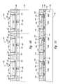
- FIGS. 4A and 4Billustrate stages in yet another embodiment of a method for wafer-level packaging of microfeature devices.
- This methodcan include several steps that are at least generally similar to those described above.
- a plurality of first known good microelectronic dies 420are releasably attached to the support member 100 in a desired arrangement and an encapsulant 460 is deposited around the peripheries of the first dies 420 to at least partially encapsulate the first dies 420 .
- This embodimentdiffers from those described above in that a redistribution layer 430 is formed on the individual first dies 420 before stacking one or more second known good microelectronic dies 440 ( FIG. 4B ) on the first dies 420 .
- the redistribution layers 430can be formed on the first dies 420 at this step because the external contacts on the second dies 440 ( FIG. 4B ) do not correspond to the arrangement of the array of terminals 426 (only one is shown) on the first dies 420 .
- the redistribution layers 430can accordingly align the contacts of the first dies 420 with corresponding contacts on the second dies 440 ( FIG. 4B ).
- one or more second dies 440have been stacked on corresponding first dies 420 to form stacked microfeature subassemblies 450 and the encapsulant 460 has been deposited onto the support member 100 (shown in broken lines) to at least partially encapsulate the subassemblies 450 .
- the support member 100is removed from the subassemblies 450 .
- the second dies 440include through-wafer interconnects 447 electrically coupling a plurality of contacts 446 at a first side 442 of the second dies 440 to a plurality of terminals 448 at a second side 444 of the second dies 440 .
- the assemblycan undergo additional processing as described above with respect to FIGS. 1E and 1F to form a plurality of microfeature devices 470 .
- FIGS. 5A-5Cillustrate stages in a method for wafer-level packaging of microfeature devices in accordance with another embodiment of the invention.
- FIG. 5Ais a side cross-sectional view of the support member 100 at an intermediate stage of the method after a plurality of first known good microelectronic dies 520 have been placed on the support member 100 in a desired arrangement.
- the first dies 520can include individual pairs of devices, such as first die 520 a with logic-type circuitry and corresponding first die 520 b with memory circuitry.
- the first dies 520can include other types of devices and/or have a different configuration.
- an encapsulant 560can be deposited onto the support member 100 and around the peripheries of the first dies 520 to at least partially encapsulate the first dies 520 .
- a plurality of second known good microelectronic dies 540can be stacked on corresponding first dies 520 to form a plurality of stacked microfeature subassemblies 550 .
- the individual second dies 540can include a first side 542 , a second side 543 opposite the first side 542 , integrated circuitry 544 (shown schematically), an image sensor 545 electrically coupled to the integrated circuitry 544 , and external contacts 546 electrically coupled to the integrated circuitry 545 .
- the external contacts 546can include a plurality of terminals 547 at the first side 542 , a plurality of contacts 548 at the second side 543 , and interconnects 549 extending through the second dies 540 electrically coupling the terminals 547 to corresponding contacts 548 .
- the subassemblies 550have been at least partially encapsulated with the encapsulant 560 .
- the encapsulant 560can be deposited onto the support member 100 using processes generally similar to those described above with respect to FIG. 1D .
- a plurality of optical elementscan be formed over the image sensors 545 on the second dies 540 .
- color filter arrays 552are formed over the individual image sensors 545 .
- the color filter arrays 552include individual filters configured to allow the wavelengths of selected colors (e.g., red, green, or blue) to pass to each pixel of the image sensors 545 by placing a filter of that color over the corresponding pixels.
- a plurality of microlensescan be formed over the color filter arrays 552 on the image sensors 545 and an oxide coating (not shown) can be deposited over the microlenses to protect the optical elements during further processing of the assembly.
- the color filter arrays 552 and/or microlensescan be formed over the image sensors 545 before encapsulating the second dies 540 .
- the support member 100FIG. 5B is removed from the encapsulated subassemblies 550 and the assembly can be cut along lines B-B to singulate the imagers 570 .
- One feature of this embodimentis that the optical elements are formed over the image sensors 545 before singulation of the imagers 570 .
- An advantage of this featureis that the image sensors 545 are protected before proceeding with singulation and subsequent packaging processes.
- the color filter arrays 552 , microlenses, and oxide coatingprotect the image sensors 545 from fluids and particles while cutting the encapsulated first and second dies 520 and 540 . A single small particle can ruin an image sensor 545 for high-end applications, such as digital cameras and picture cell phones.
- the optical elementsat the wafer level before singulating the individual imagers 570 , the image sensors 545 on the individual second dies 540 are protected during the singulation process. Further, the image sensors 545 are also protected during subsequent packaging and assembly processes.
- one or more additional layers of diesmay be stacked on the first and second known good dies in each of the embodiments described above to form stacked devices having three or more stacked dies.
- the dies described abovemay have different arrangements and/or include different features. Aspects of the invention described in the context of particular embodiments may be combined or eliminated in other embodiments. For example, any of the dies described above with reference to one embodiment may be used in any of the other above-described embodiments.
Landscapes
- Engineering & Computer Science (AREA)
- Microelectronics & Electronic Packaging (AREA)
- Power Engineering (AREA)
- Computer Hardware Design (AREA)
- Physics & Mathematics (AREA)
- Condensed Matter Physics & Semiconductors (AREA)
- General Physics & Mathematics (AREA)
- Manufacturing & Machinery (AREA)
- Encapsulation Of And Coatings For Semiconductor Or Solid State Devices (AREA)
Abstract
Description
Claims (16)
Priority Applications (1)
| Application Number | Priority Date | Filing Date | Title |
|---|---|---|---|
| US12/874,644US8704380B2 (en) | 2005-08-30 | 2010-09-02 | Methods for wafer-level packaging of microfeature devices and microfeature devices formed using such methods |
Applications Claiming Priority (2)
| Application Number | Priority Date | Filing Date | Title |
|---|---|---|---|
| US11/215,780US7807505B2 (en) | 2005-08-30 | 2005-08-30 | Methods for wafer-level packaging of microfeature devices and microfeature devices formed using such methods |
| US12/874,644US8704380B2 (en) | 2005-08-30 | 2010-09-02 | Methods for wafer-level packaging of microfeature devices and microfeature devices formed using such methods |
Related Parent Applications (1)
| Application Number | Title | Priority Date | Filing Date |
|---|---|---|---|
| US11/215,780DivisionUS7807505B2 (en) | 2005-08-30 | 2005-08-30 | Methods for wafer-level packaging of microfeature devices and microfeature devices formed using such methods |
Publications (2)
| Publication Number | Publication Date |
|---|---|
| US20100327462A1 US20100327462A1 (en) | 2010-12-30 |
| US8704380B2true US8704380B2 (en) | 2014-04-22 |
Family
ID=37802953
Family Applications (2)
| Application Number | Title | Priority Date | Filing Date |
|---|---|---|---|
| US11/215,780Active2026-08-06US7807505B2 (en) | 2005-08-30 | 2005-08-30 | Methods for wafer-level packaging of microfeature devices and microfeature devices formed using such methods |
| US12/874,644Active2027-07-30US8704380B2 (en) | 2005-08-30 | 2010-09-02 | Methods for wafer-level packaging of microfeature devices and microfeature devices formed using such methods |
Family Applications Before (1)
| Application Number | Title | Priority Date | Filing Date |
|---|---|---|---|
| US11/215,780Active2026-08-06US7807505B2 (en) | 2005-08-30 | 2005-08-30 | Methods for wafer-level packaging of microfeature devices and microfeature devices formed using such methods |
Country Status (1)
| Country | Link |
|---|---|
| US (2) | US7807505B2 (en) |
Cited By (1)
| Publication number | Priority date | Publication date | Assignee | Title |
|---|---|---|---|---|
| US20180166497A1 (en)* | 2016-12-09 | 2018-06-14 | Ams Ag | Method to produce a ruggedized package of an image sensor |
Families Citing this family (38)
| Publication number | Priority date | Publication date | Assignee | Title |
|---|---|---|---|---|
| US7807505B2 (en)* | 2005-08-30 | 2010-10-05 | Micron Technology, Inc. | Methods for wafer-level packaging of microfeature devices and microfeature devices formed using such methods |
| US7759167B2 (en)* | 2005-11-23 | 2010-07-20 | Imec | Method for embedding dies |
| US7425464B2 (en)* | 2006-03-10 | 2008-09-16 | Freescale Semiconductor, Inc. | Semiconductor device packaging |
| KR100761468B1 (en)* | 2006-07-13 | 2007-09-27 | 삼성전자주식회사 | Semiconductor Device and Forming Method |
| US7781235B2 (en)* | 2006-12-21 | 2010-08-24 | Taiwan Semiconductor Manufacturing Company, Ltd. | Chip-probing and bumping solutions for stacked dies having through-silicon vias |
| US8367471B2 (en)* | 2007-06-15 | 2013-02-05 | Micron Technology, Inc. | Semiconductor assemblies, stacked semiconductor devices, and methods of manufacturing semiconductor assemblies and stacked semiconductor devices |
| US8044497B2 (en)* | 2007-09-10 | 2011-10-25 | Intel Corporation | Stacked die package |
| US7745920B2 (en) | 2008-06-10 | 2010-06-29 | Micron Technology, Inc. | Packaged microelectronic devices and methods for manufacturing packaged microelectronic devices |
| US8048708B2 (en)* | 2008-06-25 | 2011-11-01 | Micron Technology, Inc. | Method and apparatus providing an imager module with a permanent carrier |
| US7820485B2 (en)* | 2008-09-29 | 2010-10-26 | Freescale Semiconductor, Inc. | Method of forming a package with exposed component surfaces |
| US8232140B2 (en)* | 2009-03-27 | 2012-07-31 | Taiwan Semiconductor Manufacturing Company, Ltd. | Method for ultra thin wafer handling and processing |
| JP2010251347A (en)* | 2009-04-10 | 2010-11-04 | Elpida Memory Inc | Method of manufacturing semiconductor device |
| US20110050334A1 (en) | 2009-09-02 | 2011-03-03 | Qualcomm Incorporated | Integrated Voltage Regulator with Embedded Passive Device(s) |
| TWI436470B (en) | 2009-09-30 | 2014-05-01 | Advanced Semiconductor Eng | Packaging process and package structure |
| US9772460B2 (en)* | 2010-02-23 | 2017-09-26 | Luxtera, Inc. | Method and system for implementing high-speed interfaces between semiconductor dies in optical communication systems |
| US8541886B2 (en)* | 2010-03-09 | 2013-09-24 | Stats Chippac Ltd. | Integrated circuit packaging system with via and method of manufacture thereof |
| US20110221053A1 (en)* | 2010-03-11 | 2011-09-15 | Qualcomm Incorporated | Pre-processing to reduce wafer level warpage |
| FR2960095A1 (en)* | 2010-05-17 | 2011-11-18 | St Microelectronics Grenoble 2 | METHOD FOR MANUFACTURING SEMICONDUCTOR DEVICES AND SEMICONDUCTOR DEVICE COMPRISING A THROUGH VIAS CHIP |
| US8538215B2 (en) | 2010-05-20 | 2013-09-17 | Analog Devices, Inc. | Optical package and related methods |
| US20110298139A1 (en)* | 2010-06-04 | 2011-12-08 | Yi-Shao Lai | Semiconductor Package |
| US9048112B2 (en)* | 2010-06-29 | 2015-06-02 | Qualcomm Incorporated | Integrated voltage regulator with embedded passive device(s) for a stacked IC |
| US8263435B2 (en)* | 2010-10-28 | 2012-09-11 | Stats Chippac, Ltd. | Semiconductor device and method of stacking semiconductor die in mold laser package interconnected by bumps and conductive vias |
| WO2012082092A1 (en)* | 2010-12-13 | 2012-06-21 | Arm Limited | Inter-die connection within an integrated circuit formed of a stack of circuit dies |
| US8367475B2 (en)* | 2011-03-25 | 2013-02-05 | Broadcom Corporation | Chip scale package assembly in reconstitution panel process format |
| FR2985367A1 (en)* | 2011-12-29 | 2013-07-05 | 3D Plus | METHOD FOR THE COLLECTIVE MANUFACTURE OF 3D ELECTRONIC MODULES COMPRISING ONLY VALID PCBS |
| US8772058B2 (en)* | 2012-02-02 | 2014-07-08 | Harris Corporation | Method for making a redistributed wafer using transferrable redistribution layers |
| US8842951B2 (en) | 2012-03-02 | 2014-09-23 | Analog Devices, Inc. | Systems and methods for passive alignment of opto-electronic components |
| US9716193B2 (en) | 2012-05-02 | 2017-07-25 | Analog Devices, Inc. | Integrated optical sensor module |
| TWI614858B (en)* | 2012-07-26 | 2018-02-11 | 矽品精密工業股份有限公司 | Semiconductor package and method of forming the same |
| US10884551B2 (en) | 2013-05-16 | 2021-01-05 | Analog Devices, Inc. | Integrated gesture sensor module |
| US9704841B2 (en)* | 2014-03-26 | 2017-07-11 | United Microelectronics Corp. | Method of packaging stacked dies on wafer using flip-chip bonding |
| CN105023877B (en)* | 2014-04-28 | 2019-12-24 | 联华电子股份有限公司 | Semiconductor wafer, packaging structure and manufacturing method thereof |
| KR101563909B1 (en) | 2014-08-19 | 2015-10-28 | 앰코 테크놀로지 코리아 주식회사 | Method for manufacturing Package On Package |
| US9590129B2 (en) | 2014-11-19 | 2017-03-07 | Analog Devices Global | Optical sensor module |
| KR102505189B1 (en)* | 2015-07-22 | 2023-03-02 | 인텔 코포레이션 | multi-layer package |
| US10712197B2 (en) | 2018-01-11 | 2020-07-14 | Analog Devices Global Unlimited Company | Optical sensor package |
| US10978426B2 (en)* | 2018-12-31 | 2021-04-13 | Micron Technology, Inc. | Semiconductor packages with pass-through clock traces and associated systems and methods |
| US20240063207A1 (en)* | 2022-08-19 | 2024-02-22 | Micron Technology, Inc. | Methods for fusion bonding semiconductor devices to temporary carrier wafers with cavity regions for reduced bond strength, and semiconductor device assemblies formed by the same |
Citations (134)
| Publication number | Priority date | Publication date | Assignee | Title |
|---|---|---|---|---|
| US402638A (en) | 1889-05-07 | Whiffletree | ||
| US5107328A (en) | 1991-02-13 | 1992-04-21 | Micron Technology, Inc. | Packaging means for a semiconductor die having particular shelf structure |
| US5128831A (en) | 1991-10-31 | 1992-07-07 | Micron Technology, Inc. | High-density electronic package comprising stacked sub-modules which are electrically interconnected by solder-filled vias |
| US5138434A (en) | 1991-01-22 | 1992-08-11 | Micron Technology, Inc. | Packaging for semiconductor logic devices |
| US5252857A (en) | 1991-08-05 | 1993-10-12 | International Business Machines Corporation | Stacked DCA memory chips |
| US5258236A (en) | 1991-05-03 | 1993-11-02 | Ibm Corporation | Multi-layer thin film structure and parallel processing method for fabricating same |
| US5434745A (en) | 1994-07-26 | 1995-07-18 | White Microelectronics Div. Of Bowmar Instrument Corp. | Stacked silicon die carrier assembly |
| US5518957A (en) | 1991-10-10 | 1996-05-21 | Samsung Electronics Co., Ltd. | Method for making a thin profile semiconductor package |
| US5593927A (en) | 1993-10-14 | 1997-01-14 | Micron Technology, Inc. | Method for packaging semiconductor dice |
| US5677566A (en) | 1995-05-08 | 1997-10-14 | Micron Technology, Inc. | Semiconductor chip package |
| US5696033A (en) | 1995-08-16 | 1997-12-09 | Micron Technology, Inc. | Method for packaging a semiconductor die |
| US5707881A (en) | 1996-09-03 | 1998-01-13 | Motorola, Inc. | Test structure and method for performing burn-in testing of a semiconductor product wafer |
| US5739050A (en) | 1996-01-26 | 1998-04-14 | Micron Technology, Inc. | Method and apparatus for assembling a semiconductor package for testing |
| US5739585A (en) | 1995-11-27 | 1998-04-14 | Micron Technology, Inc. | Single piece package for semiconductor die |
| USD394844S (en) | 1997-04-25 | 1998-06-02 | Micron Technology, Inc. | Temporary package for semiconductor dice |
| US5815000A (en) | 1991-06-04 | 1998-09-29 | Micron Technology, Inc. | Method for testing semiconductor dice with conventionally sized temporary packages |
| US5851845A (en) | 1995-12-18 | 1998-12-22 | Micron Technology, Inc. | Process for packaging a semiconductor die using dicing and testing |
| US5883426A (en) | 1996-04-18 | 1999-03-16 | Nec Corporation | Stack module |
| US5891753A (en) | 1997-01-24 | 1999-04-06 | Micron Technology, Inc. | Method and apparatus for packaging flip chip bare die on printed circuit boards |
| US5893726A (en) | 1997-12-15 | 1999-04-13 | Micron Technology, Inc. | Semiconductor package with pre-fabricated cover and method of fabrication |
| US5894218A (en) | 1994-04-18 | 1999-04-13 | Micron Technology, Inc. | Method and apparatus for automatically positioning electronic dice within component packages |
| US5933713A (en) | 1998-04-06 | 1999-08-03 | Micron Technology, Inc. | Method of forming overmolded chip scale package and resulting product |
| US5938956A (en) | 1996-09-10 | 1999-08-17 | Micron Technology, Inc. | Circuit and method for heating an adhesive to package or rework a semiconductor die |
| US5946553A (en) | 1991-06-04 | 1999-08-31 | Micron Technology, Inc. | Process for manufacturing a semiconductor package with bi-substrate die |
| US5958100A (en) | 1993-06-03 | 1999-09-28 | Micron Technology, Inc. | Process of making a glass semiconductor package |
| US5986209A (en) | 1997-07-09 | 1999-11-16 | Micron Technology, Inc. | Package stack via bottom leaded plastic (BLP) packaging |
| US5989941A (en) | 1997-12-12 | 1999-11-23 | Micron Technology, Inc. | Encapsulated integrated circuit packaging |
| US5990566A (en) | 1998-05-20 | 1999-11-23 | Micron Technology, Inc. | High density semiconductor package |
| US5994784A (en) | 1997-12-18 | 1999-11-30 | Micron Technology, Inc. | Die positioning in integrated circuit packaging |
| US6004867A (en) | 1996-12-16 | 1999-12-21 | Samsung Electronics Co., Ltd. | Chip-size packages assembled using mass production techniques at the wafer-level |
| US6008070A (en) | 1998-05-21 | 1999-12-28 | Micron Technology, Inc. | Wafer level fabrication and assembly of chip scale packages |
| US6008074A (en) | 1998-10-01 | 1999-12-28 | Micron Technology, Inc. | Method of forming a synchronous-link dynamic random access memory edge-mounted device |
| US6018249A (en) | 1997-12-11 | 2000-01-25 | Micron Technolgoy, Inc. | Test system with mechanical alignment for semiconductor chip scale packages and dice |
| US6020629A (en) | 1998-06-05 | 2000-02-01 | Micron Technology, Inc. | Stacked semiconductor package and method of fabrication |
| US6025728A (en) | 1997-04-25 | 2000-02-15 | Micron Technology, Inc. | Semiconductor package with wire bond protective member |
| US6028365A (en) | 1998-03-30 | 2000-02-22 | Micron Technology, Inc. | Integrated circuit package and method of fabrication |
| US6046496A (en) | 1997-11-04 | 2000-04-04 | Micron Technology Inc | Chip package |
| US6048744A (en) | 1997-09-15 | 2000-04-11 | Micron Technology, Inc. | Integrated circuit package alignment feature |
| US6048755A (en) | 1998-11-12 | 2000-04-11 | Micron Technology, Inc. | Method for fabricating BGA package using substrate with patterned solder mask open in die attach area |
| US6049125A (en) | 1997-12-29 | 2000-04-11 | Micron Technology, Inc. | Semiconductor package with heat sink and method of fabrication |
| US6051878A (en) | 1997-03-10 | 2000-04-18 | Micron Technology, Inc. | Method of constructing stacked packages |
| US6066514A (en) | 1996-10-18 | 2000-05-23 | Micron Technology, Inc. | Adhesion enhanced semiconductor die for mold compound packaging |
| US6072236A (en) | 1996-03-07 | 2000-06-06 | Micron Technology, Inc. | Micromachined chip scale package |
| US6072323A (en) | 1997-03-03 | 2000-06-06 | Micron Technology, Inc. | Temporary package, and method system for testing semiconductor dice having backside electrodes |
| US6072233A (en) | 1998-05-04 | 2000-06-06 | Micron Technology, Inc. | Stackable ball grid array package |
| US6075288A (en) | 1998-06-08 | 2000-06-13 | Micron Technology, Inc. | Semiconductor package having interlocking heat sinks and method of fabrication |
| US6081429A (en) | 1999-01-20 | 2000-06-27 | Micron Technology, Inc. | Test interposer for use with ball grid array packages assemblies and ball grid array packages including same and methods |
| US6089920A (en) | 1998-05-04 | 2000-07-18 | Micron Technology, Inc. | Modular die sockets with flexible interconnects for packaging bare semiconductor die |
| US6094058A (en) | 1991-06-04 | 2000-07-25 | Micron Technology, Inc. | Temporary semiconductor package having dense array external contacts |
| US6097087A (en) | 1997-10-31 | 2000-08-01 | Micron Technology, Inc. | Semiconductor package including flex circuit, interconnects and dense array external contacts |
| US6103547A (en) | 1997-01-17 | 2000-08-15 | Micron Technology, Inc. | High speed IC package configuration |
| US6107122A (en) | 1997-08-04 | 2000-08-22 | Micron Technology, Inc. | Direct die contact (DDC) semiconductor package |
| US6107680A (en) | 1995-01-04 | 2000-08-22 | Micron Technology, Inc. | Packaging for bare dice employing EMR-sensitive adhesives |
| US6117382A (en) | 1998-02-05 | 2000-09-12 | Micron Technology, Inc. | Method for encasing array packages |
| US6153924A (en) | 1998-02-23 | 2000-11-28 | Micron Technology, Inc. | Multilayered lead frame for semiconductor package |
| US6159764A (en) | 1997-07-02 | 2000-12-12 | Micron Technology, Inc. | Varied-thickness heat sink for integrated circuit (IC) packages and method of fabricating IC packages |
| US6163956A (en) | 1998-02-23 | 2000-12-26 | Micron Technology, Inc. | Method of making chip scale package with heat spreade |
| US6172419B1 (en) | 1998-02-24 | 2001-01-09 | Micron Technology, Inc. | Low profile ball grid array package |
| US6175149B1 (en) | 1998-02-13 | 2001-01-16 | Micron Technology, Inc. | Mounting multiple semiconductor dies in a package |
| US6184465B1 (en) | 1998-11-12 | 2001-02-06 | Micron Technology, Inc. | Semiconductor package |
| US6187615B1 (en) | 1998-08-28 | 2001-02-13 | Samsung Electronics Co., Ltd. | Chip scale packages and methods for manufacturing the chip scale packages at wafer level |
| US6188232B1 (en) | 1996-12-31 | 2001-02-13 | Micron Technology, Inc. | Temporary package, system, and method for testing semiconductor dice and chip scale packages |
| US6198172B1 (en) | 1997-02-20 | 2001-03-06 | Micron Technology, Inc. | Semiconductor chip package |
| US6208519B1 (en) | 1999-08-31 | 2001-03-27 | Micron Technology, Inc. | Thermally enhanced semiconductor package |
| US6208156B1 (en) | 1998-09-03 | 2001-03-27 | Micron Technology, Inc. | Test carrier for packaging semiconductor components having contact balls and calibration carrier for calibrating semiconductor test systems |
| US6210992B1 (en) | 1999-08-31 | 2001-04-03 | Micron Technology, Inc. | Controlling packaging encapsulant leakage |
| US6215175B1 (en) | 1998-07-06 | 2001-04-10 | Micron Technology, Inc. | Semiconductor package having metal foil die mounting plate |
| US6212767B1 (en) | 1999-08-31 | 2001-04-10 | Micron Technology, Inc. | Assembling a stacked die package |
| US6225689B1 (en) | 1998-08-21 | 2001-05-01 | Micron Technology, Inc. | Low profile multi-IC chip package connector |
| US6228548B1 (en) | 1998-02-27 | 2001-05-08 | Micron Technology, Inc. | Method of making a multichip semiconductor package |
| US6228687B1 (en) | 1999-06-28 | 2001-05-08 | Micron Technology, Inc. | Wafer-level package and methods of fabricating |
| US6229202B1 (en) | 2000-01-10 | 2001-05-08 | Micron Technology, Inc. | Semiconductor package having downset leadframe for reducing package bow |
| US6235554B1 (en) | 1995-11-27 | 2001-05-22 | Micron Technology, Inc. | Method for fabricating stackable chip scale semiconductor package |
| US6235552B1 (en) | 1999-07-09 | 2001-05-22 | Samsung Electronics Co., Ltd. | Chip scale package and method for manufacturing the same using a redistribution substrate |
| US6247629B1 (en) | 1997-09-08 | 2001-06-19 | Micron Technology, Inc. | Wire bond monitoring system for layered packages |
| US6252772B1 (en) | 1999-02-10 | 2001-06-26 | Micron Technology, Inc. | Removable heat sink bumpers on a quad flat package |
| US6252308B1 (en) | 1996-05-24 | 2001-06-26 | Micron Technology, Inc. | Packaged die PCB with heat sink encapsulant |
| US6255833B1 (en) | 1997-03-04 | 2001-07-03 | Micron Technology, Inc. | Method for testing semiconductor dice and chip scale packages |
| US6259153B1 (en) | 1998-08-20 | 2001-07-10 | Micron Technology, Inc. | Transverse hybrid LOC package |
| US6261865B1 (en) | 1998-10-06 | 2001-07-17 | Micron Technology, Inc. | Multi chip semiconductor package and method of construction |
| US6277671B1 (en) | 1998-10-20 | 2001-08-21 | Micron Technology, Inc. | Methods of forming integrated circuit packages |
| US6281577B1 (en) | 1996-06-28 | 2001-08-28 | Pac Tech-Packaging Technologies Gmbh | Chips arranged in plurality of planes and electrically connected to one another |
| US6284571B1 (en) | 1997-07-02 | 2001-09-04 | Micron Technology, Inc. | Lead frame assemblies with voltage reference plane and IC packages including same |
| US6285204B1 (en) | 1996-03-19 | 2001-09-04 | Micron Technology, Inc. | Method for testing semiconductor packages using oxide penetrating test contacts |
| US6291894B1 (en) | 1998-08-31 | 2001-09-18 | Micron Technology, Inc. | Method and apparatus for a semiconductor package for vertical surface mounting |
| US6294839B1 (en) | 1999-08-30 | 2001-09-25 | Micron Technology, Inc. | Apparatus and methods of packaging and testing die |
| US6297547B1 (en) | 1998-02-13 | 2001-10-02 | Micron Technology Inc. | Mounting multiple semiconductor dies in a package |
| US6303981B1 (en) | 1999-09-01 | 2001-10-16 | Micron Technology, Inc. | Semiconductor package having stacked dice and leadframes and method of fabrication |
| US6303985B1 (en) | 1998-11-12 | 2001-10-16 | Micron Technology, Inc. | Semiconductor lead frame and package with stiffened mounting paddle |
| US6310390B1 (en) | 1999-04-08 | 2001-10-30 | Micron Technology, Inc. | BGA package and method of fabrication |
| US6316285B1 (en) | 1998-09-02 | 2001-11-13 | Micron Technology, Inc. | Passivation layer for packaged integrated circuits |
| US6326687B1 (en) | 1998-09-01 | 2001-12-04 | Micron Technology, Inc. | IC package with dual heat spreaders |
| US6326698B1 (en) | 2000-06-08 | 2001-12-04 | Micron Technology, Inc. | Semiconductor devices having protective layers thereon through which contact pads are exposed and stereolithographic methods of fabricating such semiconductor devices |
| US6326244B1 (en) | 1998-09-03 | 2001-12-04 | Micron Technology, Inc. | Method of making a cavity ball grid array apparatus |
| US6329220B1 (en) | 1999-11-23 | 2001-12-11 | Micron Technology, Inc. | Packages for semiconductor die |
| US6331453B1 (en) | 1999-12-16 | 2001-12-18 | Micron Technology, Inc. | Method for fabricating semiconductor packages using mold tooling fixture with flash control cavities |
| US6331221B1 (en) | 1998-04-15 | 2001-12-18 | Micron Technology, Inc. | Process for providing electrical connection between a semiconductor die and a semiconductor die receiving member |
| US20020001670A1 (en) | 2000-04-24 | 2002-01-03 | Pauw Herbert De | Low cost electroless plating process for single chips and wafer parts and products obtained thereof |
| US6365434B1 (en) | 2000-06-28 | 2002-04-02 | Micron Technology, Inc. | Method and apparatus for reduced flash encapsulation of microelectronic devices |
| US6407381B1 (en) | 2000-07-05 | 2002-06-18 | Amkor Technology, Inc. | Wafer scale image sensor package |
| US20020094602A1 (en) | 2001-01-17 | 2002-07-18 | Tzong-Dar Her | DCA memory module and a fabrication method thereof |
| US20020100165A1 (en) | 2000-02-14 | 2002-08-01 | Amkor Technology, Inc. | Method of forming an integrated circuit device package using a temporary substrate |
| US6432796B1 (en) | 2000-06-28 | 2002-08-13 | Micron Technology, Inc. | Method and apparatus for marking microelectronic dies and microelectronic devices |
| US6437586B1 (en) | 1997-11-03 | 2002-08-20 | Micron Technology, Inc. | Load board socket adapter and interface method |
| US6451709B1 (en) | 1998-09-03 | 2002-09-17 | Micron Technology, Inc. | Methodology of removing misplaced encapsulant for attachment of heat sinks in a chip on board package |
| US20020130401A1 (en) | 2001-03-15 | 2002-09-19 | Chee Tay L. | Underfill applications using film technology |
| US6503780B1 (en) | 2000-07-05 | 2003-01-07 | Amkor Technology, Inc. | Wafer scale image sensor package fabrication method |
| US6548757B1 (en) | 2000-08-28 | 2003-04-15 | Micron Technology, Inc. | Microelectronic device assemblies having a shielded input and methods for manufacturing and operating such microelectronic device assemblies |
| US6548376B2 (en) | 2001-08-30 | 2003-04-15 | Micron Technology, Inc. | Methods of thinning microelectronic workpieces |
| US6552910B1 (en) | 2000-06-28 | 2003-04-22 | Micron Technology, Inc. | Stacked-die assemblies with a plurality of microelectronic devices and methods of manufacture |
| US6555400B2 (en) | 2001-08-22 | 2003-04-29 | Micron Technology, Inc. | Method for substrate mapping |
| US6560117B2 (en) | 2000-06-28 | 2003-05-06 | Micron Technology, Inc. | Packaged microelectronic die assemblies and methods of manufacture |
| US6558600B1 (en) | 2000-05-04 | 2003-05-06 | Micron Technology, Inc. | Method for packaging microelectronic substrates |
| US6561479B1 (en) | 2000-08-23 | 2003-05-13 | Micron Technology, Inc. | Small scale actuators and methods for their formation and use |
| US6564979B2 (en) | 2001-07-18 | 2003-05-20 | Micron Technology, Inc. | Method and apparatus for dispensing adhesive on microelectronic substrate supports |
| WO2003044859A1 (en)* | 2001-11-22 | 2003-05-30 | Sony Corporation | Multi-chip circuit module and method for producing the same |
| US6576494B1 (en) | 2000-06-28 | 2003-06-10 | Micron Technology, Inc. | Recessed encapsulated microelectronic devices and methods for formation |
| US6576495B1 (en) | 2000-08-30 | 2003-06-10 | Micron Technology, Inc. | Microelectronic assembly with pre-disposed fill material and associated method of manufacture |
| US6576531B2 (en) | 2001-08-24 | 2003-06-10 | Micron Technology, Inc. | Method for cutting semiconductor wafers |
| US6589820B1 (en) | 2000-06-16 | 2003-07-08 | Micron Technology, Inc. | Method and apparatus for packaging a microelectronic die |
| US6607937B1 (en) | 2000-08-23 | 2003-08-19 | Micron Technology, Inc. | Stacked microelectronic dies and methods for stacking microelectronic dies |
| US6614092B2 (en) | 2000-08-16 | 2003-09-02 | Micron Technology, Inc. | Microelectronic device package with conductive elements and associated method of manufacture |
| US6622380B1 (en) | 2002-02-12 | 2003-09-23 | Micron Technology, Inc. | Methods for manufacturing microelectronic devices and methods for mounting microelectronic packages to circuit boards |
| US6670719B2 (en) | 1999-08-25 | 2003-12-30 | Micron Technology, Inc. | Microelectronic device package filled with liquid or pressurized gas and associated method of manufacture |
| US6673649B1 (en) | 2002-07-05 | 2004-01-06 | Micron Technology, Inc. | Microelectronic device packages and methods for controlling the disposition of non-conductive materials in such packages |
| US20040214373A1 (en) | 2003-04-22 | 2004-10-28 | Tongbi Jiang | Packaged microelectronic devices and methods for packaging microelectronic devices |
| US20050104171A1 (en) | 2003-11-13 | 2005-05-19 | Benson Peter A. | Microelectronic devices having conductive complementary structures and methods of manufacturing microelectronic devices having conductive complementary structures |
| US6908784B1 (en) | 2002-03-06 | 2005-06-21 | Micron Technology, Inc. | Method for fabricating encapsulated semiconductor components |
| US20050255632A1 (en) | 2004-05-13 | 2005-11-17 | Stack Devices Corp. | Method of fabricating stacked semiconductor device |
| US20050270055A1 (en) | 2004-06-02 | 2005-12-08 | Salman Akram | Systems and methods for testing microelectronic imagers and microfeature devices |
| US20050277279A1 (en) | 2004-06-14 | 2005-12-15 | Shijian Luo | Microfeature devices and methods for manufacturing microfeature devices |
| US20060043573A1 (en) | 2004-08-30 | 2006-03-02 | Harry Hedler | Semiconductor and method for producing a semiconductor |
| US20070045875A1 (en) | 2005-08-30 | 2007-03-01 | Micron Technology, Inc. | Methods for wafer-level packaging of microfeature devices and microfeature devices formed using such methods |
| US7235431B2 (en) | 2004-09-02 | 2007-06-26 | Micron Technology, Inc. | Methods for packaging a plurality of semiconductor dice using a flowable dielectric material |
Family Cites Families (3)
| Publication number | Priority date | Publication date | Assignee | Title |
|---|---|---|---|---|
| US36469A (en) | 1862-09-16 | Improved sugar-evaporator | ||
| USD402638S (en) | 1997-04-25 | 1998-12-15 | Micron Technology, Inc. | Temporary package for semiconductor dice |
| US6285201B1 (en) | 1997-10-06 | 2001-09-04 | Micron Technology, Inc. | Method and apparatus for capacitively testing a semiconductor die |
- 2005
- 2005-08-30USUS11/215,780patent/US7807505B2/enactiveActive
- 2010
- 2010-09-02USUS12/874,644patent/US8704380B2/enactiveActive
Patent Citations (154)
| Publication number | Priority date | Publication date | Assignee | Title |
|---|---|---|---|---|
| US402638A (en) | 1889-05-07 | Whiffletree | ||
| US5138434A (en) | 1991-01-22 | 1992-08-11 | Micron Technology, Inc. | Packaging for semiconductor logic devices |
| US5107328A (en) | 1991-02-13 | 1992-04-21 | Micron Technology, Inc. | Packaging means for a semiconductor die having particular shelf structure |
| US5258236A (en) | 1991-05-03 | 1993-11-02 | Ibm Corporation | Multi-layer thin film structure and parallel processing method for fabricating same |
| US5815000A (en) | 1991-06-04 | 1998-09-29 | Micron Technology, Inc. | Method for testing semiconductor dice with conventionally sized temporary packages |
| US6020624A (en) | 1991-06-04 | 2000-02-01 | Micron Technology, Inc. | Semiconductor package with bi-substrate die |
| US5946553A (en) | 1991-06-04 | 1999-08-31 | Micron Technology, Inc. | Process for manufacturing a semiconductor package with bi-substrate die |
| US6094058A (en) | 1991-06-04 | 2000-07-25 | Micron Technology, Inc. | Temporary semiconductor package having dense array external contacts |
| US5252857A (en) | 1991-08-05 | 1993-10-12 | International Business Machines Corporation | Stacked DCA memory chips |
| US5518957A (en) | 1991-10-10 | 1996-05-21 | Samsung Electronics Co., Ltd. | Method for making a thin profile semiconductor package |
| US5128831A (en) | 1991-10-31 | 1992-07-07 | Micron Technology, Inc. | High-density electronic package comprising stacked sub-modules which are electrically interconnected by solder-filled vias |
| US5958100A (en) | 1993-06-03 | 1999-09-28 | Micron Technology, Inc. | Process of making a glass semiconductor package |
| US5593927A (en) | 1993-10-14 | 1997-01-14 | Micron Technology, Inc. | Method for packaging semiconductor dice |
| US6064194A (en) | 1994-04-18 | 2000-05-16 | Micron Technology, Inc. | Method and apparatus for automatically positioning electronic dice within component packages |
| US5894218A (en) | 1994-04-18 | 1999-04-13 | Micron Technology, Inc. | Method and apparatus for automatically positioning electronic dice within component packages |
| US5434745A (en) | 1994-07-26 | 1995-07-18 | White Microelectronics Div. Of Bowmar Instrument Corp. | Stacked silicon die carrier assembly |
| US6107680A (en) | 1995-01-04 | 2000-08-22 | Micron Technology, Inc. | Packaging for bare dice employing EMR-sensitive adhesives |
| US5677566A (en) | 1995-05-08 | 1997-10-14 | Micron Technology, Inc. | Semiconductor chip package |
| US5696033A (en) | 1995-08-16 | 1997-12-09 | Micron Technology, Inc. | Method for packaging a semiconductor die |
| US6235554B1 (en) | 1995-11-27 | 2001-05-22 | Micron Technology, Inc. | Method for fabricating stackable chip scale semiconductor package |
| US5739585A (en) | 1995-11-27 | 1998-04-14 | Micron Technology, Inc. | Single piece package for semiconductor die |
| US5851845A (en) | 1995-12-18 | 1998-12-22 | Micron Technology, Inc. | Process for packaging a semiconductor die using dicing and testing |
| US5739050A (en) | 1996-01-26 | 1998-04-14 | Micron Technology, Inc. | Method and apparatus for assembling a semiconductor package for testing |
| US6072236A (en) | 1996-03-07 | 2000-06-06 | Micron Technology, Inc. | Micromachined chip scale package |
| US6124634A (en) | 1996-03-07 | 2000-09-26 | Micron Technology, Inc. | Micromachined chip scale package |
| US6285204B1 (en) | 1996-03-19 | 2001-09-04 | Micron Technology, Inc. | Method for testing semiconductor packages using oxide penetrating test contacts |
| US5883426A (en) | 1996-04-18 | 1999-03-16 | Nec Corporation | Stack module |
| US6252308B1 (en) | 1996-05-24 | 2001-06-26 | Micron Technology, Inc. | Packaged die PCB with heat sink encapsulant |
| US20010015492A1 (en) | 1996-05-24 | 2001-08-23 | Salman Akram | Packaged die on pcb with heat sink encapsulant |
| US6281577B1 (en) | 1996-06-28 | 2001-08-28 | Pac Tech-Packaging Technologies Gmbh | Chips arranged in plurality of planes and electrically connected to one another |
| US5707881A (en) | 1996-09-03 | 1998-01-13 | Motorola, Inc. | Test structure and method for performing burn-in testing of a semiconductor product wafer |
| US5938956A (en) | 1996-09-10 | 1999-08-17 | Micron Technology, Inc. | Circuit and method for heating an adhesive to package or rework a semiconductor die |
| US6066514A (en) | 1996-10-18 | 2000-05-23 | Micron Technology, Inc. | Adhesion enhanced semiconductor die for mold compound packaging |
| US6004867A (en) | 1996-12-16 | 1999-12-21 | Samsung Electronics Co., Ltd. | Chip-size packages assembled using mass production techniques at the wafer-level |
| US6188232B1 (en) | 1996-12-31 | 2001-02-13 | Micron Technology, Inc. | Temporary package, system, and method for testing semiconductor dice and chip scale packages |
| US6103547A (en) | 1997-01-17 | 2000-08-15 | Micron Technology, Inc. | High speed IC package configuration |
| US5891753A (en) | 1997-01-24 | 1999-04-06 | Micron Technology, Inc. | Method and apparatus for packaging flip chip bare die on printed circuit boards |
| US5898224A (en) | 1997-01-24 | 1999-04-27 | Micron Technology, Inc. | Apparatus for packaging flip chip bare die on printed circuit boards |
| US6198172B1 (en) | 1997-02-20 | 2001-03-06 | Micron Technology, Inc. | Semiconductor chip package |
| US6072323A (en) | 1997-03-03 | 2000-06-06 | Micron Technology, Inc. | Temporary package, and method system for testing semiconductor dice having backside electrodes |
| US6255833B1 (en) | 1997-03-04 | 2001-07-03 | Micron Technology, Inc. | Method for testing semiconductor dice and chip scale packages |
| US6051878A (en) | 1997-03-10 | 2000-04-18 | Micron Technology, Inc. | Method of constructing stacked packages |
| USD394844S (en) | 1997-04-25 | 1998-06-02 | Micron Technology, Inc. | Temporary package for semiconductor dice |
| US6025728A (en) | 1997-04-25 | 2000-02-15 | Micron Technology, Inc. | Semiconductor package with wire bond protective member |
| US6159764A (en) | 1997-07-02 | 2000-12-12 | Micron Technology, Inc. | Varied-thickness heat sink for integrated circuit (IC) packages and method of fabricating IC packages |
| US6284571B1 (en) | 1997-07-02 | 2001-09-04 | Micron Technology, Inc. | Lead frame assemblies with voltage reference plane and IC packages including same |
| US5986209A (en) | 1997-07-09 | 1999-11-16 | Micron Technology, Inc. | Package stack via bottom leaded plastic (BLP) packaging |
| US6150717A (en) | 1997-08-04 | 2000-11-21 | Micron Technology, Inc. | Direct die contact (DDC) semiconductor package |
| US6107122A (en) | 1997-08-04 | 2000-08-22 | Micron Technology, Inc. | Direct die contact (DDC) semiconductor package |
| US6247629B1 (en) | 1997-09-08 | 2001-06-19 | Micron Technology, Inc. | Wire bond monitoring system for layered packages |
| US6246108B1 (en) | 1997-09-15 | 2001-06-12 | Micron Technology, Inc. | Integrated circuit package including lead frame with electrically isolated alignment feature |
| US6048744A (en) | 1997-09-15 | 2000-04-11 | Micron Technology, Inc. | Integrated circuit package alignment feature |
| US6097087A (en) | 1997-10-31 | 2000-08-01 | Micron Technology, Inc. | Semiconductor package including flex circuit, interconnects and dense array external contacts |
| US6437586B1 (en) | 1997-11-03 | 2002-08-20 | Micron Technology, Inc. | Load board socket adapter and interface method |
| US6046496A (en) | 1997-11-04 | 2000-04-04 | Micron Technology Inc | Chip package |
| US6018249A (en) | 1997-12-11 | 2000-01-25 | Micron Technolgoy, Inc. | Test system with mechanical alignment for semiconductor chip scale packages and dice |
| US5989941A (en) | 1997-12-12 | 1999-11-23 | Micron Technology, Inc. | Encapsulated integrated circuit packaging |
| US5893726A (en) | 1997-12-15 | 1999-04-13 | Micron Technology, Inc. | Semiconductor package with pre-fabricated cover and method of fabrication |
| US5994784A (en) | 1997-12-18 | 1999-11-30 | Micron Technology, Inc. | Die positioning in integrated circuit packaging |
| US6326242B1 (en) | 1997-12-29 | 2001-12-04 | Micron Technology, Inc. | Semiconductor package with heat sink and method of fabrication |
| US6049125A (en) | 1997-12-29 | 2000-04-11 | Micron Technology, Inc. | Semiconductor package with heat sink and method of fabrication |
| US6332766B1 (en) | 1998-02-05 | 2001-12-25 | Micron Technology, Inc. | Apparatus for encasing array packages |
| US6117382A (en) | 1998-02-05 | 2000-09-12 | Micron Technology, Inc. | Method for encasing array packages |
| US6297547B1 (en) | 1998-02-13 | 2001-10-02 | Micron Technology Inc. | Mounting multiple semiconductor dies in a package |
| US6175149B1 (en) | 1998-02-13 | 2001-01-16 | Micron Technology, Inc. | Mounting multiple semiconductor dies in a package |
| US6163956A (en) | 1998-02-23 | 2000-12-26 | Micron Technology, Inc. | Method of making chip scale package with heat spreade |
| US6153924A (en) | 1998-02-23 | 2000-11-28 | Micron Technology, Inc. | Multilayered lead frame for semiconductor package |
| US6314639B1 (en) | 1998-02-23 | 2001-11-13 | Micron Technology, Inc. | Chip scale package with heat spreader and method of manufacture |
| US6172419B1 (en) | 1998-02-24 | 2001-01-09 | Micron Technology, Inc. | Low profile ball grid array package |
| US6228548B1 (en) | 1998-02-27 | 2001-05-08 | Micron Technology, Inc. | Method of making a multichip semiconductor package |
| US6429528B1 (en) | 1998-02-27 | 2002-08-06 | Micron Technology, Inc. | Multichip semiconductor package |
| US6028365A (en) | 1998-03-30 | 2000-02-22 | Micron Technology, Inc. | Integrated circuit package and method of fabrication |
| US5933713A (en) | 1998-04-06 | 1999-08-03 | Micron Technology, Inc. | Method of forming overmolded chip scale package and resulting product |
| US6331221B1 (en) | 1998-04-15 | 2001-12-18 | Micron Technology, Inc. | Process for providing electrical connection between a semiconductor die and a semiconductor die receiving member |
| US6089920A (en) | 1998-05-04 | 2000-07-18 | Micron Technology, Inc. | Modular die sockets with flexible interconnects for packaging bare semiconductor die |
| US6072233A (en) | 1998-05-04 | 2000-06-06 | Micron Technology, Inc. | Stackable ball grid array package |
| US5990566A (en) | 1998-05-20 | 1999-11-23 | Micron Technology, Inc. | High density semiconductor package |
| US6008070A (en) | 1998-05-21 | 1999-12-28 | Micron Technology, Inc. | Wafer level fabrication and assembly of chip scale packages |
| US6326697B1 (en) | 1998-05-21 | 2001-12-04 | Micron Technology, Inc. | Hermetically sealed chip scale packages formed by wafer level fabrication and assembly |
| US6020629A (en) | 1998-06-05 | 2000-02-01 | Micron Technology, Inc. | Stacked semiconductor package and method of fabrication |
| US6075288A (en) | 1998-06-08 | 2000-06-13 | Micron Technology, Inc. | Semiconductor package having interlocking heat sinks and method of fabrication |
| US6215175B1 (en) | 1998-07-06 | 2001-04-10 | Micron Technology, Inc. | Semiconductor package having metal foil die mounting plate |
| US6259153B1 (en) | 1998-08-20 | 2001-07-10 | Micron Technology, Inc. | Transverse hybrid LOC package |
| US6258623B1 (en) | 1998-08-21 | 2001-07-10 | Micron Technology, Inc. | Low profile multi-IC chip package connector |
| US6225689B1 (en) | 1998-08-21 | 2001-05-01 | Micron Technology, Inc. | Low profile multi-IC chip package connector |
| US6187615B1 (en) | 1998-08-28 | 2001-02-13 | Samsung Electronics Co., Ltd. | Chip scale packages and methods for manufacturing the chip scale packages at wafer level |
| US6291894B1 (en) | 1998-08-31 | 2001-09-18 | Micron Technology, Inc. | Method and apparatus for a semiconductor package for vertical surface mounting |
| US6326687B1 (en) | 1998-09-01 | 2001-12-04 | Micron Technology, Inc. | IC package with dual heat spreaders |
| US6316285B1 (en) | 1998-09-02 | 2001-11-13 | Micron Technology, Inc. | Passivation layer for packaged integrated circuits |
| US6451709B1 (en) | 1998-09-03 | 2002-09-17 | Micron Technology, Inc. | Methodology of removing misplaced encapsulant for attachment of heat sinks in a chip on board package |
| US6326244B1 (en) | 1998-09-03 | 2001-12-04 | Micron Technology, Inc. | Method of making a cavity ball grid array apparatus |
| US6208156B1 (en) | 1998-09-03 | 2001-03-27 | Micron Technology, Inc. | Test carrier for packaging semiconductor components having contact balls and calibration carrier for calibrating semiconductor test systems |
| US6008074A (en) | 1998-10-01 | 1999-12-28 | Micron Technology, Inc. | Method of forming a synchronous-link dynamic random access memory edge-mounted device |
| US6261865B1 (en) | 1998-10-06 | 2001-07-17 | Micron Technology, Inc. | Multi chip semiconductor package and method of construction |
| US6277671B1 (en) | 1998-10-20 | 2001-08-21 | Micron Technology, Inc. | Methods of forming integrated circuit packages |
| US6048755A (en) | 1998-11-12 | 2000-04-11 | Micron Technology, Inc. | Method for fabricating BGA package using substrate with patterned solder mask open in die attach area |
| US6303985B1 (en) | 1998-11-12 | 2001-10-16 | Micron Technology, Inc. | Semiconductor lead frame and package with stiffened mounting paddle |
| US6184465B1 (en) | 1998-11-12 | 2001-02-06 | Micron Technology, Inc. | Semiconductor package |
| US6081429A (en) | 1999-01-20 | 2000-06-27 | Micron Technology, Inc. | Test interposer for use with ball grid array packages assemblies and ball grid array packages including same and methods |
| US6252772B1 (en) | 1999-02-10 | 2001-06-26 | Micron Technology, Inc. | Removable heat sink bumpers on a quad flat package |
| US6310390B1 (en) | 1999-04-08 | 2001-10-30 | Micron Technology, Inc. | BGA package and method of fabrication |
| US6228687B1 (en) | 1999-06-28 | 2001-05-08 | Micron Technology, Inc. | Wafer-level package and methods of fabricating |
| US6235552B1 (en) | 1999-07-09 | 2001-05-22 | Samsung Electronics Co., Ltd. | Chip scale package and method for manufacturing the same using a redistribution substrate |
| US6670719B2 (en) | 1999-08-25 | 2003-12-30 | Micron Technology, Inc. | Microelectronic device package filled with liquid or pressurized gas and associated method of manufacture |
| US6294839B1 (en) | 1999-08-30 | 2001-09-25 | Micron Technology, Inc. | Apparatus and methods of packaging and testing die |
| US6212767B1 (en) | 1999-08-31 | 2001-04-10 | Micron Technology, Inc. | Assembling a stacked die package |
| US6208519B1 (en) | 1999-08-31 | 2001-03-27 | Micron Technology, Inc. | Thermally enhanced semiconductor package |
| US6210992B1 (en) | 1999-08-31 | 2001-04-03 | Micron Technology, Inc. | Controlling packaging encapsulant leakage |
| US6303981B1 (en) | 1999-09-01 | 2001-10-16 | Micron Technology, Inc. | Semiconductor package having stacked dice and leadframes and method of fabrication |
| US6329220B1 (en) | 1999-11-23 | 2001-12-11 | Micron Technology, Inc. | Packages for semiconductor die |
| US6331453B1 (en) | 1999-12-16 | 2001-12-18 | Micron Technology, Inc. | Method for fabricating semiconductor packages using mold tooling fixture with flash control cavities |
| US6258624B1 (en) | 2000-01-10 | 2001-07-10 | Micron Technology, Inc. | Semiconductor package having downset leadframe for reducing package bow |
| US6229202B1 (en) | 2000-01-10 | 2001-05-08 | Micron Technology, Inc. | Semiconductor package having downset leadframe for reducing package bow |
| US20020100165A1 (en) | 2000-02-14 | 2002-08-01 | Amkor Technology, Inc. | Method of forming an integrated circuit device package using a temporary substrate |
| US20020001670A1 (en) | 2000-04-24 | 2002-01-03 | Pauw Herbert De | Low cost electroless plating process for single chips and wafer parts and products obtained thereof |
| US6558600B1 (en) | 2000-05-04 | 2003-05-06 | Micron Technology, Inc. | Method for packaging microelectronic substrates |
| US6326698B1 (en) | 2000-06-08 | 2001-12-04 | Micron Technology, Inc. | Semiconductor devices having protective layers thereon through which contact pads are exposed and stereolithographic methods of fabricating such semiconductor devices |
| US6589820B1 (en) | 2000-06-16 | 2003-07-08 | Micron Technology, Inc. | Method and apparatus for packaging a microelectronic die |
| US6653173B2 (en) | 2000-06-16 | 2003-11-25 | Micron Technology, Inc. | Method and apparatus for packaging a microelectronic die |
| US6432796B1 (en) | 2000-06-28 | 2002-08-13 | Micron Technology, Inc. | Method and apparatus for marking microelectronic dies and microelectronic devices |
| US6576494B1 (en) | 2000-06-28 | 2003-06-10 | Micron Technology, Inc. | Recessed encapsulated microelectronic devices and methods for formation |
| US6365434B1 (en) | 2000-06-28 | 2002-04-02 | Micron Technology, Inc. | Method and apparatus for reduced flash encapsulation of microelectronic devices |
| US6644949B2 (en) | 2000-06-28 | 2003-11-11 | Micron Technology, Inc. | Apparatus for reduced flash encapsulation of microelectronic devices |
| US6552910B1 (en) | 2000-06-28 | 2003-04-22 | Micron Technology, Inc. | Stacked-die assemblies with a plurality of microelectronic devices and methods of manufacture |
| US6638595B2 (en) | 2000-06-28 | 2003-10-28 | Micron Technology, Inc. | Method and apparatus for reduced flash encapsulation of microelectronic devices |
| US6560117B2 (en) | 2000-06-28 | 2003-05-06 | Micron Technology, Inc. | Packaged microelectronic die assemblies and methods of manufacture |
| US6407381B1 (en) | 2000-07-05 | 2002-06-18 | Amkor Technology, Inc. | Wafer scale image sensor package |
| US6503780B1 (en) | 2000-07-05 | 2003-01-07 | Amkor Technology, Inc. | Wafer scale image sensor package fabrication method |
| US6614092B2 (en) | 2000-08-16 | 2003-09-02 | Micron Technology, Inc. | Microelectronic device package with conductive elements and associated method of manufacture |
| US6672325B2 (en) | 2000-08-23 | 2004-01-06 | Micron Technology, Inc. | Small scale actuators and methods for their formation and use |
| US6607937B1 (en) | 2000-08-23 | 2003-08-19 | Micron Technology, Inc. | Stacked microelectronic dies and methods for stacking microelectronic dies |
| US6561479B1 (en) | 2000-08-23 | 2003-05-13 | Micron Technology, Inc. | Small scale actuators and methods for their formation and use |
| US6548757B1 (en) | 2000-08-28 | 2003-04-15 | Micron Technology, Inc. | Microelectronic device assemblies having a shielded input and methods for manufacturing and operating such microelectronic device assemblies |
| US6576495B1 (en) | 2000-08-30 | 2003-06-10 | Micron Technology, Inc. | Microelectronic assembly with pre-disposed fill material and associated method of manufacture |
| US20020094602A1 (en) | 2001-01-17 | 2002-07-18 | Tzong-Dar Her | DCA memory module and a fabrication method thereof |
| US20020130401A1 (en) | 2001-03-15 | 2002-09-19 | Chee Tay L. | Underfill applications using film technology |
| US6564979B2 (en) | 2001-07-18 | 2003-05-20 | Micron Technology, Inc. | Method and apparatus for dispensing adhesive on microelectronic substrate supports |
| US6555400B2 (en) | 2001-08-22 | 2003-04-29 | Micron Technology, Inc. | Method for substrate mapping |
| US6888159B2 (en) | 2001-08-22 | 2005-05-03 | Micron Technology, Inc. | Substrate mapping |
| US6576531B2 (en) | 2001-08-24 | 2003-06-10 | Micron Technology, Inc. | Method for cutting semiconductor wafers |
| US6548376B2 (en) | 2001-08-30 | 2003-04-15 | Micron Technology, Inc. | Methods of thinning microelectronic workpieces |
| WO2003044859A1 (en)* | 2001-11-22 | 2003-05-30 | Sony Corporation | Multi-chip circuit module and method for producing the same |
| US20040056344A1 (en)* | 2001-11-22 | 2004-03-25 | Tsuyoshi Ogawa | Multi-chip circuit module and method for producing the same |
| US6622380B1 (en) | 2002-02-12 | 2003-09-23 | Micron Technology, Inc. | Methods for manufacturing microelectronic devices and methods for mounting microelectronic packages to circuit boards |
| US6908784B1 (en) | 2002-03-06 | 2005-06-21 | Micron Technology, Inc. | Method for fabricating encapsulated semiconductor components |
| US6673649B1 (en) | 2002-07-05 | 2004-01-06 | Micron Technology, Inc. | Microelectronic device packages and methods for controlling the disposition of non-conductive materials in such packages |
| US20040214373A1 (en) | 2003-04-22 | 2004-10-28 | Tongbi Jiang | Packaged microelectronic devices and methods for packaging microelectronic devices |
| US20050104171A1 (en) | 2003-11-13 | 2005-05-19 | Benson Peter A. | Microelectronic devices having conductive complementary structures and methods of manufacturing microelectronic devices having conductive complementary structures |
| US20050255632A1 (en) | 2004-05-13 | 2005-11-17 | Stack Devices Corp. | Method of fabricating stacked semiconductor device |
| US20050270055A1 (en) | 2004-06-02 | 2005-12-08 | Salman Akram | Systems and methods for testing microelectronic imagers and microfeature devices |
| US20050277279A1 (en) | 2004-06-14 | 2005-12-15 | Shijian Luo | Microfeature devices and methods for manufacturing microfeature devices |
| US20060043573A1 (en) | 2004-08-30 | 2006-03-02 | Harry Hedler | Semiconductor and method for producing a semiconductor |
| US7235431B2 (en) | 2004-09-02 | 2007-06-26 | Micron Technology, Inc. | Methods for packaging a plurality of semiconductor dice using a flowable dielectric material |
| US20070045875A1 (en) | 2005-08-30 | 2007-03-01 | Micron Technology, Inc. | Methods for wafer-level packaging of microfeature devices and microfeature devices formed using such methods |
Cited By (1)
| Publication number | Priority date | Publication date | Assignee | Title |
|---|---|---|---|---|
| US20180166497A1 (en)* | 2016-12-09 | 2018-06-14 | Ams Ag | Method to produce a ruggedized package of an image sensor |
Also Published As
| Publication number | Publication date |
|---|---|
| US20100327462A1 (en) | 2010-12-30 |
| US20070045875A1 (en) | 2007-03-01 |
| US7807505B2 (en) | 2010-10-05 |
Similar Documents
| Publication | Publication Date | Title |
|---|---|---|
| US8704380B2 (en) | Methods for wafer-level packaging of microfeature devices and microfeature devices formed using such methods | |
| US8138613B2 (en) | Microelectronic devices | |
| US6946325B2 (en) | Methods for packaging microelectronic devices | |
| US12322705B2 (en) | Chip package and manufacturing method thereof | |
| US7749808B2 (en) | Stacked microelectronic devices and methods for manufacturing microelectronic devices | |
| US7572725B2 (en) | Methods for wafer-level packaging of microelectronic devices and microelectronic devices formed by such methods | |
| US8482113B2 (en) | Semiconductor device | |
| EP2171754A1 (en) | Semiconductor assemblies, stacked semiconductor devices, and methods of manufacturing semiconductor assemblies and stacked semiconductor devices | |
| US7674640B2 (en) | Stacked die package system | |
| US11417569B2 (en) | Package structure having integrated circuit component with conductive terminals of different dimensions | |
| WO2007024483A2 (en) | Microelectronic devices, stacked microelectronic devices, and methods for manufacturing microelectronic devices | |
| TWI727261B (en) | Method of manufacturing a package-on-package type semiconductor package | |
| US20240387469A1 (en) | Semiconductor packages | |
| US20160031707A1 (en) | Microelectronic devices and methods for manufacturing microelectronic devices | |
| TWI845113B (en) | Multi-die package and method of manufacturing the same | |
| CN116864456A (en) | Multi-die packaging and manufacturing method | |
| EP1289010A1 (en) | Semiconductor device without use of chip carrier and method of making the same |
Legal Events
| Date | Code | Title | Description |
|---|---|---|---|
| FEPP | Fee payment procedure | Free format text:PAYOR NUMBER ASSIGNED (ORIGINAL EVENT CODE: ASPN); ENTITY STATUS OF PATENT OWNER: LARGE ENTITY | |
| STCF | Information on status: patent grant | Free format text:PATENTED CASE | |
| CC | Certificate of correction | ||
| AS | Assignment | Owner name:U.S. BANK NATIONAL ASSOCIATION, AS COLLATERAL AGENT, CALIFORNIA Free format text:SECURITY INTEREST;ASSIGNOR:MICRON TECHNOLOGY, INC.;REEL/FRAME:038669/0001 Effective date:20160426 Owner name:U.S. BANK NATIONAL ASSOCIATION, AS COLLATERAL AGEN Free format text:SECURITY INTEREST;ASSIGNOR:MICRON TECHNOLOGY, INC.;REEL/FRAME:038669/0001 Effective date:20160426 | |
| AS | Assignment | Owner name:MORGAN STANLEY SENIOR FUNDING, INC., AS COLLATERAL AGENT, MARYLAND Free format text:PATENT SECURITY AGREEMENT;ASSIGNOR:MICRON TECHNOLOGY, INC.;REEL/FRAME:038954/0001 Effective date:20160426 Owner name:MORGAN STANLEY SENIOR FUNDING, INC., AS COLLATERAL Free format text:PATENT SECURITY AGREEMENT;ASSIGNOR:MICRON TECHNOLOGY, INC.;REEL/FRAME:038954/0001 Effective date:20160426 | |
| AS | Assignment | Owner name:U.S. BANK NATIONAL ASSOCIATION, AS COLLATERAL AGENT, CALIFORNIA Free format text:CORRECTIVE ASSIGNMENT TO CORRECT THE REPLACE ERRONEOUSLY FILED PATENT #7358718 WITH THE CORRECT PATENT #7358178 PREVIOUSLY RECORDED ON REEL 038669 FRAME 0001. ASSIGNOR(S) HEREBY CONFIRMS THE SECURITY INTEREST;ASSIGNOR:MICRON TECHNOLOGY, INC.;REEL/FRAME:043079/0001 Effective date:20160426 Owner name:U.S. BANK NATIONAL ASSOCIATION, AS COLLATERAL AGEN Free format text:CORRECTIVE ASSIGNMENT TO CORRECT THE REPLACE ERRONEOUSLY FILED PATENT #7358718 WITH THE CORRECT PATENT #7358178 PREVIOUSLY RECORDED ON REEL 038669 FRAME 0001. ASSIGNOR(S) HEREBY CONFIRMS THE SECURITY INTEREST;ASSIGNOR:MICRON TECHNOLOGY, INC.;REEL/FRAME:043079/0001 Effective date:20160426 | |
| MAFP | Maintenance fee payment | Free format text:PAYMENT OF MAINTENANCE FEE, 4TH YEAR, LARGE ENTITY (ORIGINAL EVENT CODE: M1551) Year of fee payment:4 | |
| AS | Assignment | Owner name:JPMORGAN CHASE BANK, N.A., AS COLLATERAL AGENT, ILLINOIS Free format text:SECURITY INTEREST;ASSIGNORS:MICRON TECHNOLOGY, INC.;MICRON SEMICONDUCTOR PRODUCTS, INC.;REEL/FRAME:047540/0001 Effective date:20180703 Owner name:JPMORGAN CHASE BANK, N.A., AS COLLATERAL AGENT, IL Free format text:SECURITY INTEREST;ASSIGNORS:MICRON TECHNOLOGY, INC.;MICRON SEMICONDUCTOR PRODUCTS, INC.;REEL/FRAME:047540/0001 Effective date:20180703 | |
| AS | Assignment | Owner name:MICRON TECHNOLOGY, INC., IDAHO Free format text:RELEASE BY SECURED PARTY;ASSIGNOR:U.S. BANK NATIONAL ASSOCIATION, AS COLLATERAL AGENT;REEL/FRAME:047243/0001 Effective date:20180629 | |
| AS | Assignment | Owner name:MICRON TECHNOLOGY, INC., IDAHO Free format text:RELEASE BY SECURED PARTY;ASSIGNOR:MORGAN STANLEY SENIOR FUNDING, INC., AS COLLATERAL AGENT;REEL/FRAME:050937/0001 Effective date:20190731 | |
| AS | Assignment | Owner name:MICRON SEMICONDUCTOR PRODUCTS, INC., IDAHO Free format text:RELEASE BY SECURED PARTY;ASSIGNOR:JPMORGAN CHASE BANK, N.A., AS COLLATERAL AGENT;REEL/FRAME:051028/0001 Effective date:20190731 Owner name:MICRON TECHNOLOGY, INC., IDAHO Free format text:RELEASE BY SECURED PARTY;ASSIGNOR:JPMORGAN CHASE BANK, N.A., AS COLLATERAL AGENT;REEL/FRAME:051028/0001 Effective date:20190731 | |
| MAFP | Maintenance fee payment | Free format text:PAYMENT OF MAINTENANCE FEE, 8TH YEAR, LARGE ENTITY (ORIGINAL EVENT CODE: M1552); ENTITY STATUS OF PATENT OWNER: LARGE ENTITY Year of fee payment:8 |