US8702578B2 - Positioning device and method for positioning a load - Google Patents
Positioning device and method for positioning a loadDownload PDFInfo
- Publication number
- US8702578B2 US8702578B2US12/130,826US13082608AUS8702578B2US 8702578 B2US8702578 B2US 8702578B2US 13082608 AUS13082608 AUS 13082608AUS 8702578 B2US8702578 B2US 8702578B2
- Authority
- US
- United States
- Prior art keywords
- robotic arm
- mass
- positioning
- motor
- load
- Prior art date
- Legal status (The legal status is an assumption and is not a legal conclusion. Google has not performed a legal analysis and makes no representation as to the accuracy of the status listed.)
- Active, expires
Links
- 238000000034methodMethods0.000titleclaimsdescription17
- 238000005259measurementMethods0.000claimsabstractdescription32
- 238000011156evaluationMethods0.000claimsabstractdescription20
- 239000002245particleSubstances0.000claimsdescription21
- 238000011282treatmentMethods0.000claimsdescription16
- 230000005484gravityEffects0.000claimsdescription12
- 238000002727particle therapyMethods0.000claimsdescription12
- 238000003745diagnosisMethods0.000claimsdescription6
- 238000001959radiotherapyMethods0.000claimsdescription2
- 238000004891communicationMethods0.000claims3
- 230000001678irradiating effectEffects0.000claims1
- 230000005489elastic deformationEffects0.000description8
- 238000007665saggingMethods0.000description5
- 206010028980NeoplasmDiseases0.000description4
- 150000002500ionsChemical class0.000description4
- 230000007257malfunctionEffects0.000description4
- -1helium ionsChemical class0.000description3
- 230000005855radiationEffects0.000description3
- 229910052799carbonInorganic materials0.000description2
- 238000010276constructionMethods0.000description2
- 230000003068static effectEffects0.000description2
- 238000012935AveragingMethods0.000description1
- 241000920340PionSpecies0.000description1
- 229910001423beryllium ionInorganic materials0.000description1
- 201000011510cancerDiseases0.000description1
- 230000001447compensatory effectEffects0.000description1
- 229910052734heliumInorganic materials0.000description1
- 239000001307heliumSubstances0.000description1
- NJPPVKZQTLUDBO-UHFFFAOYSA-NnovaluronChemical compoundC1=C(Cl)C(OC(F)(F)C(OC(F)(F)F)F)=CC=C1NC(=O)NC(=O)C1=C(F)C=CC=C1FNJPPVKZQTLUDBO-UHFFFAOYSA-N0.000description1
- 238000000275quality assuranceMethods0.000description1
- 238000012546transferMethods0.000description1
Images


Classifications
- A—HUMAN NECESSITIES
- A61—MEDICAL OR VETERINARY SCIENCE; HYGIENE
- A61B—DIAGNOSIS; SURGERY; IDENTIFICATION
- A61B6/00—Apparatus or devices for radiation diagnosis; Apparatus or devices for radiation diagnosis combined with radiation therapy equipment
- A61B6/40—Arrangements for generating radiation specially adapted for radiation diagnosis
- A61B6/4064—Arrangements for generating radiation specially adapted for radiation diagnosis specially adapted for producing a particular type of beam
- A61B6/4092—Arrangements for generating radiation specially adapted for radiation diagnosis specially adapted for producing a particular type of beam for producing synchrotron radiation
- A—HUMAN NECESSITIES
- A61—MEDICAL OR VETERINARY SCIENCE; HYGIENE
- A61B—DIAGNOSIS; SURGERY; IDENTIFICATION
- A61B6/00—Apparatus or devices for radiation diagnosis; Apparatus or devices for radiation diagnosis combined with radiation therapy equipment
- A61B6/04—Positioning of patients; Tiltable beds or the like
- A61B6/0487—Motor-assisted positioning
- A—HUMAN NECESSITIES
- A61—MEDICAL OR VETERINARY SCIENCE; HYGIENE
- A61B—DIAGNOSIS; SURGERY; IDENTIFICATION
- A61B6/00—Apparatus or devices for radiation diagnosis; Apparatus or devices for radiation diagnosis combined with radiation therapy equipment
- A61B6/52—Devices using data or image processing specially adapted for radiation diagnosis
- A61B6/5258—Devices using data or image processing specially adapted for radiation diagnosis involving detection or reduction of artifacts or noise
- A61B6/5264—Devices using data or image processing specially adapted for radiation diagnosis involving detection or reduction of artifacts or noise due to motion
- A61B6/5276—Devices using data or image processing specially adapted for radiation diagnosis involving detection or reduction of artifacts or noise due to motion involving measuring table sag
- A—HUMAN NECESSITIES
- A61—MEDICAL OR VETERINARY SCIENCE; HYGIENE
- A61G—TRANSPORT, PERSONAL CONVEYANCES, OR ACCOMMODATION SPECIALLY ADAPTED FOR PATIENTS OR DISABLED PERSONS; OPERATING TABLES OR CHAIRS; CHAIRS FOR DENTISTRY; FUNERAL DEVICES
- A61G13/00—Operating tables; Auxiliary appliances therefor
- A61G13/02—Adjustable operating tables; Controls therefor
- A—HUMAN NECESSITIES
- A61—MEDICAL OR VETERINARY SCIENCE; HYGIENE
- A61N—ELECTROTHERAPY; MAGNETOTHERAPY; RADIATION THERAPY; ULTRASOUND THERAPY
- A61N5/00—Radiation therapy
- A61N5/10—X-ray therapy; Gamma-ray therapy; Particle-irradiation therapy
- A61N5/1048—Monitoring, verifying, controlling systems and methods
- A61N5/1049—Monitoring, verifying, controlling systems and methods for verifying the position of the patient with respect to the radiation beam
- B—PERFORMING OPERATIONS; TRANSPORTING
- B25—HAND TOOLS; PORTABLE POWER-DRIVEN TOOLS; MANIPULATORS
- B25J—MANIPULATORS; CHAMBERS PROVIDED WITH MANIPULATION DEVICES
- B25J9/00—Programme-controlled manipulators
- B25J9/16—Programme controls
- B25J9/1628—Programme controls characterised by the control loop
- B25J9/1638—Programme controls characterised by the control loop compensation for arm bending/inertia, pay load weight/inertia
- A—HUMAN NECESSITIES
- A61—MEDICAL OR VETERINARY SCIENCE; HYGIENE
- A61G—TRANSPORT, PERSONAL CONVEYANCES, OR ACCOMMODATION SPECIALLY ADAPTED FOR PATIENTS OR DISABLED PERSONS; OPERATING TABLES OR CHAIRS; CHAIRS FOR DENTISTRY; FUNERAL DEVICES
- A61G13/00—Operating tables; Auxiliary appliances therefor
- A61G13/02—Adjustable operating tables; Controls therefor
- A61G13/04—Adjustable operating tables; Controls therefor tiltable around transverse or longitudinal axis
- A—HUMAN NECESSITIES
- A61—MEDICAL OR VETERINARY SCIENCE; HYGIENE
- A61G—TRANSPORT, PERSONAL CONVEYANCES, OR ACCOMMODATION SPECIALLY ADAPTED FOR PATIENTS OR DISABLED PERSONS; OPERATING TABLES OR CHAIRS; CHAIRS FOR DENTISTRY; FUNERAL DEVICES
- A61G13/00—Operating tables; Auxiliary appliances therefor
- A61G13/02—Adjustable operating tables; Controls therefor
- A61G13/06—Adjustable operating tables; Controls therefor raising or lowering of the whole table surface
- A—HUMAN NECESSITIES
- A61—MEDICAL OR VETERINARY SCIENCE; HYGIENE
- A61N—ELECTROTHERAPY; MAGNETOTHERAPY; RADIATION THERAPY; ULTRASOUND THERAPY
- A61N5/00—Radiation therapy
- A61N5/10—X-ray therapy; Gamma-ray therapy; Particle-irradiation therapy
- A61N5/1048—Monitoring, verifying, controlling systems and methods
- A61N5/1049—Monitoring, verifying, controlling systems and methods for verifying the position of the patient with respect to the radiation beam
- A61N2005/1057—Monitoring, verifying, controlling systems and methods for verifying the position of the patient with respect to the radiation beam monitoring flexing of the patient support or the radiation treatment apparatus
- G—PHYSICS
- G05—CONTROLLING; REGULATING
- G05B—CONTROL OR REGULATING SYSTEMS IN GENERAL; FUNCTIONAL ELEMENTS OF SUCH SYSTEMS; MONITORING OR TESTING ARRANGEMENTS FOR SUCH SYSTEMS OR ELEMENTS
- G05B2219/00—Program-control systems
- G05B2219/30—Nc systems
- G05B2219/35—Nc in input of data, input till input file format
- G05B2219/35285—Plausibility check for data, within permissible range
- G—PHYSICS
- G05—CONTROLLING; REGULATING
- G05B—CONTROL OR REGULATING SYSTEMS IN GENERAL; FUNCTIONAL ELEMENTS OF SUCH SYSTEMS; MONITORING OR TESTING ARRANGEMENTS FOR SUCH SYSTEMS OR ELEMENTS
- G05B2219/00—Program-control systems
- G05B2219/30—Nc systems
- G05B2219/37—Measurements
- G05B2219/37285—Load, current taken by motor
- G—PHYSICS
- G05—CONTROLLING; REGULATING
- G05B—CONTROL OR REGULATING SYSTEMS IN GENERAL; FUNCTIONAL ELEMENTS OF SUCH SYSTEMS; MONITORING OR TESTING ARRANGEMENTS FOR SUCH SYSTEMS OR ELEMENTS
- G05B2219/00—Program-control systems
- G05B2219/30—Nc systems
- G05B2219/39—Robotics, robotics to robotics hand
- G05B2219/39176—Compensation deflection arm
- G—PHYSICS
- G05—CONTROLLING; REGULATING
- G05B—CONTROL OR REGULATING SYSTEMS IN GENERAL; FUNCTIONAL ELEMENTS OF SUCH SYSTEMS; MONITORING OR TESTING ARRANGEMENTS FOR SUCH SYSTEMS OR ELEMENTS
- G05B2219/00—Program-control systems
- G05B2219/30—Nc systems
- G05B2219/45—Nc applications
- G05B2219/45117—Medical, radio surgery manipulator
- G—PHYSICS
- G05—CONTROLLING; REGULATING
- G05B—CONTROL OR REGULATING SYSTEMS IN GENERAL; FUNCTIONAL ELEMENTS OF SUCH SYSTEMS; MONITORING OR TESTING ARRANGEMENTS FOR SUCH SYSTEMS OR ELEMENTS
- G05B2219/00—Program-control systems
- G05B2219/30—Nc systems
- G05B2219/49—Nc machine tool, till multiple
- G05B2219/49189—Bending of driven table, lag between real and commanded position
Definitions
- the present embodimentsrelate to positioning a load.
- a particle beamfor example, including protons or heavy ions, is generated in an accelerator.
- the particle beamis carried in a radiation channel from the accelerator to an exit window of the radiation channel.
- the particle beamenters an irradiation or treatment room through the exit window.
- the particle beammay be used to treat cancer.
- the success of tumor treatmentdepends on the precision of the tumor positioning. Positioning a patient depends on a plurality of factors. For example, the precision of positioning depends on how the patient is supported and the rigidity of the patient support system. In positioning the patient, the weight of the patient may cause elastic deformation that leads to imprecise positioning.
- a more-rigid constructionmay be used to avoid elastic deformation under the load of the patient.
- the more-rigid constructionresults in higher costs.
- a loadis ascertained simply, flexibly, and economically.
- a positioning device for positioning a loadincludes a motor, measuring device, and an evaluation device.
- the motormoves the positioning device.
- the measuring deviceis associated with the motor and is operable to ascertain (determine) measurement data that characterizes the motor current consumption by the motor in the positioning of the load.
- the evaluation devicemay evaluate the measurement data, so that the loading of the positioning device by the load may be ascertained.
- the motor current consumption, the force, and/or the torque that act on the motormay be ascertained.
- the loading of the positioning device by the loadmay be attained, for example, without additional sensors.
- the load data of the loadsuch as the weight and/or the location of the load on the positioning device, may be ascertained at least in part with the positioning device.
- the load data of the loaddoes not need to be known prior to treatment.
- an elastic deformationfor instance, may be quantitatively predicted from the loading.
- the elastic deformationmay be predicated, for example, via a relationship based on empirical values and/or a relationship ascertained by calculation.
- the deviation in an actual position of the load from a desired set-point positionmay be ascertained.
- a warning signalmay be output if the ascertained loading is above a threshold value, or if the expected elastic deformation exceeds a tolerance range.
- the positioning devicefurther includes at least one further motor for moving the positioning device; and a further measuring device.
- the further measuring deviceis associated with the further motor and is operable to ascertain further measurement data that characterizes the motor current consumption by the further motor in the positioning of the load.
- the evaluation devicemay take into account the further measurement data, in addition to the measurement data, during the evaluation. Because the motor current consumption of further motors is measured, the loading of the positioning device may be ascertained more precisely. For example, loading, or load data, may be ascertained redundantly. The loading may be ascertained more precisely, because variables whose ascertainment requires the measurement data of at least two different motors may be ascertained.
- the positioning deviceadditionally has a control device for positioning the positioning device.
- the control devicemay use the ascertained loading to compensate for a deformation.
- the elastic deformation of the positioning devicecan be determined from it. To that end, a relationship based for instance on experience and/or on calculation can be used. Next, a compensation signal can be ascertained, with which the control device corrects the position of the positioning device accordingly, so that the desired set-point position is reached.
- the evaluation deviceis operable to ascertain the weight of the load and/or the position of the center of gravity of the load. For example, the position of the load, relative to the positioning device, may be ascertained.
- the positioning deviceis a multiaxial robot arm with a plurality of joints.
- the loadmay be flexibly positioned.
- the loading of the positioning devicee.g., a robot arm
- a deformation of the positioning device by the loadmay be compensated for.
- At least one joint positionmay be taken into account. At least one joint position may be taken into account whenever the robot arm used in the positioning includes different joint positions for one of the joints.
- the geometry of the robot armmay be ascertained using the joint position. The geometry of the robot arm may be used to ascertain the center of gravity of the load or the weight of the load. However, if the robot arm for positioning the load has similar joint positions that differ only slightly from one another, then the at least one joint position may not be considered when ascertaining the load, since the geometry of the robot arm varies only insignificantly.
- the positioning devicemay be a patient positioning device for positioning a patient in a medical system, such as in a particle therapy system. This offers a solution to the problem of positioning a patient as precisely as possible in the medical system, and may increase the safety of the system.
- a method for operating a positioning device for positioning a loadincludes positioning the load by moving the positioning device with the aid of the at least one motor; ascertaining (determining) measurement data that characterize a motor current consumption by the at least one motor in the positioning of the load; evaluating the ascertained measurement data in such a way that loading of the positioning device by the load is ascertained.
- the methodmay further include controlling the positioning device using the ascertained loading of the positioning device in such a way that a deformation of the positioning device by the load is compensated for.
- the methodcan be implemented, for example, based on software in a computer unit that is connected to the positioning device for controlling the positioning device.
- the weight of the load and/or the position of the center of gravity of the loadmay, for example be determined as load data.
- the ascertained loading of the positioning devicemay be subjected to a plausibility check, and may increase the reliability of the method.
- the loading in a positioning devicesuch as a multiaxial robot arm having a plurality of joints may be ascertained. At least one joint position may be taken into account.
- the positioning devicehas a plurality of motors, and measurement data is ascertained for each of the motors, the measurement data characterizing the respective motor current consumption in the positioning of the load, then the loading of the positioning device by the load may be ascertained redundantly. For example, an error signal may be output if in the redundant ascertainment a deviation is found that is outside a tolerance range. An error signal may indicate a malfunction of the positioning device, so that motion of the positioning device may be blocked, for example, for safety reasons.
- a medical diagnosis and/or treatment systemincludes a positioning device for a patient.
- the positioning deviceis located in a examination room or treatment room, and the positioning device may include the features discussed above or below.
- the medical diagnosis and/or treatment systemmay be used for radiation therapy, such as particle therapy.
- FIG. 1illustrates one embodiment of a particle therapy system
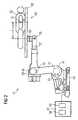
- FIG. 2illustrates one embodiment of a positioning device for a patient
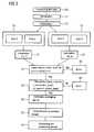
- FIG. 3illustrates a flow chart for a method for ascertaining the loading of a patient positioning device.
- FIG. 1shows a particle therapy system 10 .
- the particle therapy system 10may be used to irradiate a body, such as tissue diseased by tumor, with a particle beam.
- the particlesmay be ions, protons, pions, helium ions, carbon ions, or other types of ions.
- the particlesmay be generated in a particle source 11 . If, as shown in FIG. 1 , there are two particle sources 11 , which generate different types of particles, then a fast switchover between these two types of particles is possible.
- a switching magnet 12may be, for example, used for the fast switchover.
- the switching magnet 12is located between the particle sources 11 and a preaccelerator 13 .
- the particle therapy system 10may, for example, be operated with protons and with carbon ions simultaneously.
- the preaccelerator 13is, for example, a linear accelerator (LINAC for “LINear ACcelerator”).
- the particlesare fed into an accelerator 15 , such as a synchrotron or cyclotron.
- the particlesare accelerated to radiation treatment energies.
- a high-energy beam transport system 17carries the particle beam to one or more treatment rooms 19 . In the treatment room 19 , the accelerated particles are aimed at a body to be irradiated.
- the accelerated particlesmay be aimed at a body either from a fixed direction (e.g., in a “fixed beam” room) or from various directions via a movable gantry 21 that is rotatable about an axis 22 (e.g., in a “gantry-based” room).
- a fixed directione.g., in a “fixed beam” room
- a movable gantry 21that is rotatable about an axis 22 (e.g., in a “gantry-based” room).
- FIG. 2shows a positioning device as a robot arm 31 .
- the robot arm 31for a patient 55 , may be used in a treatment room of a particle therapy system.
- the robot arm 31has six different joints 33 , 35 , 37 , 39 , 41 , 43 , which are moved by a motor 45 , 47 .
- the motors 45 , 47are located behind the linings of the robot arm 31 .
- Measuring devices 49 , 51are located on (connected to) each of the motors 45 , 47 , and with them, measurement data that characterizes the motor current consumption at the respective motor 45 , 47 upon positioning a patient may be ascertained.
- the motors 45 , 47 and the associated measuring devices 49 , 51are shown at only two joints 39 , 41 , for the sake of simplicity.
- a measuring device 49 , 51 associated with one of the motors 45 , 47does not need to be located in the immediate vicinity of a motor, as shown.
- the measuring device 49 , 51may be located in a control unit for the motors 45 , 47 .
- the measurement datais carried to an evaluation device 53 .
- the evaluation device 53may ascertain the load data for the positioning device.
- the load data for the positioning devicemay include the weight m of the patient 55 and the location l of the center of gravity 57 of the patient 55 .
- the load datamay be used for oppositely controlling the joints 33 , 35 , 37 , 39 , 41 , 43 of the robot arm 31 in such a way to compensate for the deformation caused by loading of the positioning device. Compensation may be done, for example, by the control device 59 , with which a compensatory motion of the robot 31 may be executed.
- the evaluation device 53 and the control device 59may be implemented, for example, in a computer unit 61 that is connected to the robot arm 31 .
- the control device 59may compensate for sagging of the components of the table system 63 .
- Saggingmay include, for example, sagging of the tabletop 65 , sagging of the table pedestal, or sagging of the tabletop and of the accessories affixed to it.
- FIG. 3shows a flow chart of an embodiment of a method for ascertaining load of a positioning device 31 , for example, as shown in FIG. 2 .
- Proportionalityexists between the motor current consumption I n for a joint n and the torque M n acting on the joint.
- the torque M nis the result of the geometry of the robot arm (position of the individual joints 33 , 35 , 37 , 39 , 41 , 43 ) and of the location of the center of gravity of the patient (“l”) and the weight of the patient (“m”).
- the location l and weight mmay be unknown variables. Since the geometry (e.g., the position of the individual joints 33 , 35 , 37 , 39 , 41 , 43 ) is known, and the motor current consumption may be ascertained with the measuring devices 49 , 51 , the loading of the positioning device by a patient may be ascertained during the positioning 69 .
- a first measurement 75 of the motor current consumptionis made at two different joints. Using the first measurement 75 , a first calculation 77 of the weight of the patient m 1 and of the location of the center of gravity 11 of the patient may be performed.
- a second measurement 79 of the motor current consumptionis made at two further, different joints.
- the weight of the patient m 2 and the location of the center of gravity 12 of the patientmay be calculated in a second calculation 81 .
- a redundancy check 83may be performed. If the variables calculated in the first calculation 77 and in the second calculation 81 differ too greatly, for example, if the difference between the associated torques is greater than a predetermined threshold value ⁇ , this is an indication of a malfunction of the system.
- a first error signal 85may be output.
- the variables calculatedmay be subjected to a plausibility check 87 .
- the plausibility check 87may generate a second error signal 89 whenever one of the two calculated values is outside a predetermined tolerance range.
- the error signalmay indicate a malfunction of the system.
- an arithmetic averaging 91 of the weight m 1 , m 2 , calculated twice, of the patient and of the center of gravity 11 , 12 of the patient, calculated twice,may be performed.
- the averaged variablesmay be transferred as variables to a computer unit (value transfer 93 ). These variables may, for example, be used to perform a control 95 of the positioning system, in such a way that compensation for an elastic deformation of the positioning system in positioning the patient is performed.
- a quality check of the positioning system in the context of a quality assurance actis performed daily.
- the positioning systemis loaded with a defined load, such as with load data known in advance.
- the methodis performed, and the values transferred to the variables may be compared with reference values. When the transferred values are outside a predetermined tolerance range, a malfunction of the positioning device may have occurred.
Landscapes
- Health & Medical Sciences (AREA)
- Engineering & Computer Science (AREA)
- Life Sciences & Earth Sciences (AREA)
- Biomedical Technology (AREA)
- Medical Informatics (AREA)
- Animal Behavior & Ethology (AREA)
- General Health & Medical Sciences (AREA)
- Public Health (AREA)
- Veterinary Medicine (AREA)
- Pathology (AREA)
- Nuclear Medicine, Radiotherapy & Molecular Imaging (AREA)
- Radiology & Medical Imaging (AREA)
- Physics & Mathematics (AREA)
- Surgery (AREA)
- High Energy & Nuclear Physics (AREA)
- Biophysics (AREA)
- Optics & Photonics (AREA)
- Heart & Thoracic Surgery (AREA)
- Molecular Biology (AREA)
- Computer Vision & Pattern Recognition (AREA)
- Robotics (AREA)
- Mechanical Engineering (AREA)
- Toxicology (AREA)
- Accommodation For Nursing Or Treatment Tables (AREA)
- Radiation-Therapy Devices (AREA)
- Manipulator (AREA)
Abstract
Description
Claims (20)
Applications Claiming Priority (3)
| Application Number | Priority Date | Filing Date | Title |
|---|---|---|---|
| DE102007026114 | 2007-06-05 | ||
| DE102007026114.6 | 2007-06-05 | ||
| DE102007026114ADE102007026114A1 (en) | 2007-06-05 | 2007-06-05 | Positioning device and method for positioning a load and medical diagnostic and / or therapy system |
Publications (2)
| Publication Number | Publication Date |
|---|---|
| US20080301872A1 US20080301872A1 (en) | 2008-12-11 |
| US8702578B2true US8702578B2 (en) | 2014-04-22 |
Family
ID=39942040
Family Applications (1)
| Application Number | Title | Priority Date | Filing Date |
|---|---|---|---|
| US12/130,826Active2031-04-13US8702578B2 (en) | 2007-06-05 | 2008-05-30 | Positioning device and method for positioning a load |
Country Status (3)
| Country | Link |
|---|---|
| US (1) | US8702578B2 (en) |
| EP (1) | EP2075097B1 (en) |
| DE (1) | DE102007026114A1 (en) |
Cited By (9)
| Publication number | Priority date | Publication date | Assignee | Title |
|---|---|---|---|---|
| US9661736B2 (en) | 2014-02-20 | 2017-05-23 | Mevion Medical Systems, Inc. | Scanning system for a particle therapy system |
| US9962560B2 (en) | 2013-12-20 | 2018-05-08 | Mevion Medical Systems, Inc. | Collimator and energy degrader |
| US10258810B2 (en) | 2013-09-27 | 2019-04-16 | Mevion Medical Systems, Inc. | Particle beam scanning |
| US10646728B2 (en) | 2015-11-10 | 2020-05-12 | Mevion Medical Systems, Inc. | Adaptive aperture |
| US10653892B2 (en) | 2017-06-30 | 2020-05-19 | Mevion Medical Systems, Inc. | Configurable collimator controlled using linear motors |
| US10675487B2 (en) | 2013-12-20 | 2020-06-09 | Mevion Medical Systems, Inc. | Energy degrader enabling high-speed energy switching |
| US10925147B2 (en) | 2016-07-08 | 2021-02-16 | Mevion Medical Systems, Inc. | Treatment planning |
| US11103730B2 (en) | 2017-02-23 | 2021-08-31 | Mevion Medical Systems, Inc. | Automated treatment in particle therapy |
| US11291861B2 (en) | 2019-03-08 | 2022-04-05 | Mevion Medical Systems, Inc. | Delivery of radiation by column and generating a treatment plan therefor |
Families Citing this family (24)
| Publication number | Priority date | Publication date | Assignee | Title |
|---|---|---|---|---|
| EP1749550A1 (en)* | 2005-08-04 | 2007-02-07 | Institut Curie | Method and apparatus for applying radiotherapy |
| JP4687784B2 (en)* | 2008-12-22 | 2011-05-25 | トヨタ自動車株式会社 | Transfer support apparatus and control method thereof |
| JP4692642B2 (en) | 2009-01-22 | 2011-06-01 | トヨタ自動車株式会社 | Transfer support device |
| US8499379B2 (en)* | 2010-07-30 | 2013-08-06 | Toyota Motor Engineering & Manufacturing North America, Inc. | Robotic posture transfer assist devices and methods |
| DE102010037548A1 (en) | 2010-09-15 | 2012-03-15 | Walter Maschinenbau Gmbh | Method for operating a gripping device |
| US8584281B2 (en)* | 2011-04-07 | 2013-11-19 | Mizuho Orthopedic Systems, Inc | Surgery table having coordinated motion |
| US9925394B2 (en)* | 2011-06-08 | 2018-03-27 | Varian Medical Systems, Inc. | Automatic health detection for motion axes in medical linear accelerators |
| CN102357050A (en)* | 2011-10-21 | 2012-02-22 | 深圳市泰乐康科技有限公司 | Position display device for medical bed |
| DE102012201608A1 (en)* | 2012-02-03 | 2013-08-08 | Siemens Aktiengesellschaft | Medical device and method for determining the mass of a patient |
| DE102012201783B4 (en)* | 2012-02-07 | 2022-08-04 | Siemens Healthcare Gmbh | Method for determining the patient mass of a patient with a patient table and device with a patient table |
| JP6222795B2 (en)* | 2012-06-20 | 2017-11-01 | 東芝メディカルシステムズ株式会社 | Diagnostic imaging apparatus and control method thereof |
| US10195663B2 (en)* | 2012-08-31 | 2019-02-05 | Voodoo Robotics, Inc. | Robotic storage and retrieval systems and methods |
| DE102016104146B4 (en)* | 2016-03-08 | 2025-01-02 | Gebr. Heller Maschinenfabrik Gmbh | machine tool with workpiece mass detection |
| DE102016104324A1 (en) | 2016-03-09 | 2017-09-14 | Gerd Straßmann | Storage and positioning of tumor patients for radiotherapy |
| DE102016210500B4 (en)* | 2016-06-14 | 2020-09-17 | Kuka Roboter Gmbh | Patient positioning device and medical workstation |
| DE102016210497A1 (en)* | 2016-06-14 | 2017-12-14 | Kuka Roboter Gmbh | Patient positioning device and medical workstation |
| DE102016211538A1 (en)* | 2016-06-27 | 2017-12-28 | Leoni Kabel Gmbh | Robot and robot arrangement for patient positioning |
| CN206518552U (en)* | 2016-08-31 | 2017-09-26 | 通用电气公司 | Height-adjustable |
| CN108245357B (en)* | 2016-12-28 | 2020-07-14 | 美好罗伯特有限公司 | Mechanical operating table and hybrid operating room system |
| JP6563891B2 (en)* | 2016-12-28 | 2019-08-21 | 株式会社メディカロイド | Robotic operating table and hybrid operating room |
| DE102019101595B3 (en)* | 2019-01-23 | 2020-03-12 | Franka Emika Gmbh | Method for determining a weight and a center of gravity of a robot manipulator load |
| JP7349605B2 (en)* | 2019-06-04 | 2023-09-25 | パナソニックIpマネジメント株式会社 | How to control the robot |
| WO2022240894A1 (en)* | 2021-05-11 | 2022-11-17 | Celestial Oncology Inc. | Coupled robotic radiation therapy system |
| DE102022110888A1 (en) | 2022-05-03 | 2023-11-09 | MAQUET GmbH | SAFETY SYSTEM FOR DETECTING ERRORS IN MEDICAL TABLES |
Citations (7)
| Publication number | Priority date | Publication date | Assignee | Title |
|---|---|---|---|---|
| US4475160A (en)* | 1980-12-30 | 1984-10-02 | Fanuc Ltd. | Method of sensing abnormal condition in robot control apparatus |
| US4894595A (en)* | 1987-04-08 | 1990-01-16 | Matsushita Electric Industrial Co., Ltd. | Industrial robot |
| US5299288A (en)* | 1990-05-11 | 1994-03-29 | International Business Machines Corporation | Image-directed robotic system for precise robotic surgery including redundant consistency checking |
| DE19918140A1 (en) | 1999-04-01 | 2000-10-12 | Deutsch Zentr Luft & Raumfahrt | Measuring arrangement for controlling robots, machine tools and the like as well as a measuring method carried out with this measuring arrangement |
| DE10312025A1 (en) | 2003-03-18 | 2004-10-07 | Delta-X GmbH Ingenieurgesellschaft Gesellschaft für Strukturanalyse | Position control error compensation method for machine, involves compensation mechanism for deformations of processing machines with continuously measuring circuit utilized on basis of finite element method computation |
| DE102004013174A1 (en) | 2004-03-17 | 2005-10-06 | Wolfgang Wilhelm | Particle, X ray or light radiation unit has patient table positioned by arm of three axis industrial robot drive |
| US20050234327A1 (en)* | 2004-04-06 | 2005-10-20 | Saracen Michael J | Robotic arm for patient positioning assembly |
Family Cites Families (5)
| Publication number | Priority date | Publication date | Assignee | Title |
|---|---|---|---|---|
| DE4340960C1 (en)* | 1993-12-01 | 1994-11-10 | Siemens Ag | Patient-bearing device for medical examination units |
| US8010180B2 (en)* | 2002-03-06 | 2011-08-30 | Mako Surgical Corp. | Haptic guidance system and method |
| JP4054748B2 (en)* | 2003-10-21 | 2008-03-05 | ジーイー・メディカル・システムズ・グローバル・テクノロジー・カンパニー・エルエルシー | Top plate control method, patient support apparatus, and X-ray imaging apparatus |
| JP4519472B2 (en)* | 2004-01-19 | 2010-08-04 | ジーイー・メディカル・システムズ・グローバル・テクノロジー・カンパニー・エルエルシー | Subject weight detection method and MRI apparatus |
| EP1749550A1 (en)* | 2005-08-04 | 2007-02-07 | Institut Curie | Method and apparatus for applying radiotherapy |
- 2007
- 2007-06-05DEDE102007026114Apatent/DE102007026114A1/ennot_activeCeased
- 2008
- 2008-05-29EPEP08104154.3Apatent/EP2075097B1/enactiveActive
- 2008-05-30USUS12/130,826patent/US8702578B2/enactiveActive
Patent Citations (7)
| Publication number | Priority date | Publication date | Assignee | Title |
|---|---|---|---|---|
| US4475160A (en)* | 1980-12-30 | 1984-10-02 | Fanuc Ltd. | Method of sensing abnormal condition in robot control apparatus |
| US4894595A (en)* | 1987-04-08 | 1990-01-16 | Matsushita Electric Industrial Co., Ltd. | Industrial robot |
| US5299288A (en)* | 1990-05-11 | 1994-03-29 | International Business Machines Corporation | Image-directed robotic system for precise robotic surgery including redundant consistency checking |
| DE19918140A1 (en) | 1999-04-01 | 2000-10-12 | Deutsch Zentr Luft & Raumfahrt | Measuring arrangement for controlling robots, machine tools and the like as well as a measuring method carried out with this measuring arrangement |
| DE10312025A1 (en) | 2003-03-18 | 2004-10-07 | Delta-X GmbH Ingenieurgesellschaft Gesellschaft für Strukturanalyse | Position control error compensation method for machine, involves compensation mechanism for deformations of processing machines with continuously measuring circuit utilized on basis of finite element method computation |
| DE102004013174A1 (en) | 2004-03-17 | 2005-10-06 | Wolfgang Wilhelm | Particle, X ray or light radiation unit has patient table positioned by arm of three axis industrial robot drive |
| US20050234327A1 (en)* | 2004-04-06 | 2005-10-20 | Saracen Michael J | Robotic arm for patient positioning assembly |
Non-Patent Citations (1)
| Title |
|---|
| German Office Action dated Mar. 17, 2008 with English translation. |
Cited By (20)
| Publication number | Priority date | Publication date | Assignee | Title |
|---|---|---|---|---|
| US10258810B2 (en) | 2013-09-27 | 2019-04-16 | Mevion Medical Systems, Inc. | Particle beam scanning |
| US10456591B2 (en) | 2013-09-27 | 2019-10-29 | Mevion Medical Systems, Inc. | Particle beam scanning |
| US9962560B2 (en) | 2013-12-20 | 2018-05-08 | Mevion Medical Systems, Inc. | Collimator and energy degrader |
| US10675487B2 (en) | 2013-12-20 | 2020-06-09 | Mevion Medical Systems, Inc. | Energy degrader enabling high-speed energy switching |
| US10434331B2 (en) | 2014-02-20 | 2019-10-08 | Mevion Medical Systems, Inc. | Scanning system |
| US11717700B2 (en) | 2014-02-20 | 2023-08-08 | Mevion Medical Systems, Inc. | Scanning system |
| US9661736B2 (en) | 2014-02-20 | 2017-05-23 | Mevion Medical Systems, Inc. | Scanning system for a particle therapy system |
| US11213697B2 (en) | 2015-11-10 | 2022-01-04 | Mevion Medical Systems, Inc. | Adaptive aperture |
| US10646728B2 (en) | 2015-11-10 | 2020-05-12 | Mevion Medical Systems, Inc. | Adaptive aperture |
| US10786689B2 (en) | 2015-11-10 | 2020-09-29 | Mevion Medical Systems, Inc. | Adaptive aperture |
| US11786754B2 (en) | 2015-11-10 | 2023-10-17 | Mevion Medical Systems, Inc. | Adaptive aperture |
| US12150235B2 (en) | 2016-07-08 | 2024-11-19 | Mevion Medical Systems, Inc. | Treatment planning |
| US10925147B2 (en) | 2016-07-08 | 2021-02-16 | Mevion Medical Systems, Inc. | Treatment planning |
| US11103730B2 (en) | 2017-02-23 | 2021-08-31 | Mevion Medical Systems, Inc. | Automated treatment in particle therapy |
| US10653892B2 (en) | 2017-06-30 | 2020-05-19 | Mevion Medical Systems, Inc. | Configurable collimator controlled using linear motors |
| US11311746B2 (en) | 2019-03-08 | 2022-04-26 | Mevion Medical Systems, Inc. | Collimator and energy degrader for a particle therapy system |
| US11717703B2 (en) | 2019-03-08 | 2023-08-08 | Mevion Medical Systems, Inc. | Delivery of radiation by column and generating a treatment plan therefor |
| US11291861B2 (en) | 2019-03-08 | 2022-04-05 | Mevion Medical Systems, Inc. | Delivery of radiation by column and generating a treatment plan therefor |
| US12161885B2 (en) | 2019-03-08 | 2024-12-10 | Mevion Medical Systems, Inc. | Delivery of radiation by column and generating a treatment plan therefor |
| US12168147B2 (en) | 2019-03-08 | 2024-12-17 | Mevion Medical Systems, Inc. | Collimator and energy degrader for a particle therapy system |
Also Published As
| Publication number | Publication date |
|---|---|
| US20080301872A1 (en) | 2008-12-11 |
| DE102007026114A1 (en) | 2008-12-11 |
| EP2075097A2 (en) | 2009-07-01 |
| EP2075097A3 (en) | 2017-12-06 |
| EP2075097B1 (en) | 2021-06-30 |
Similar Documents
| Publication | Publication Date | Title |
|---|---|---|
| US8702578B2 (en) | Positioning device and method for positioning a load | |
| US10568964B2 (en) | Neutron capture therapy system and therapy planning system for neutron capture therapy | |
| JP4130680B2 (en) | Treatment apparatus and bed positioning apparatus using ion beam | |
| US7989785B2 (en) | Gantry, particle therapy system, and method for operating a gantry | |
| US8964937B2 (en) | Methods and systems in radiotherapy | |
| JP2010537784A (en) | Patient support device | |
| US8488739B2 (en) | Linear kinematics system with rotatable treatment head | |
| JP6596679B1 (en) | Patient transport cart, particle beam irradiation system, and particle beam irradiation method | |
| US11247073B2 (en) | Particle radiation therapy apparatus | |
| JPH11313900A (en) | Radiation therapy bed system | |
| US20030206611A1 (en) | Planning system for convergent radiation treatment | |
| EP3219362B1 (en) | Radiation therapy apparatus and quality control method for radiation therapy apparatus | |
| CN110582327A (en) | Beam profile measuring system | |
| US20100138997A1 (en) | Patient transport unit and method for transporting a patient | |
| US20090281658A1 (en) | Medical facility and method of docking a positioning device with a shuttle | |
| Feain et al. | the design and function of a horizontal patient rotation system for the purposes of fixed‐beam cancer radiotherapy | |
| US9839794B2 (en) | Particle beam therapy apparatus | |
| US20150119626A1 (en) | Image guided radiation therapy apparatus | |
| JP2018148937A (en) | Radiotherapy device and treatment table positioning device | |
| US20160332002A1 (en) | Particle beam irradiation system | |
| Sommer | Industrial robots for patient support | |
| US20250177781A1 (en) | Synchronization control apparatus, synchronization control method, and heavy particle beam irradiation system | |
| CN102553088A (en) | Radiation Treatment Equipment | |
| WO2023243144A1 (en) | Radiation therapy system and method for controlling same | |
| Georg et al. | Pre-clinical evaluation of an inverse planning module for segmental MLC based IMRT delivery |
Legal Events
| Date | Code | Title | Description |
|---|---|---|---|
| AS | Assignment | Owner name:SIEMENS AKTIENGESELLSCHAFT, GERMANY Free format text:ASSIGNMENT OF ASSIGNORS INTEREST;ASSIGNORS:FAHRIG, WOLFRAM;HERRMANN, KLAUS;LOSEKEN, JOCHEN MIGUEL;SIGNING DATES FROM 20080623 TO 20080626;REEL/FRAME:021320/0304 Owner name:SIEMENS AKTIENGESELLSCHAFT, GERMANY Free format text:ASSIGNMENT OF ASSIGNORS INTEREST;ASSIGNORS:FAHRIG, WOLFRAM;HERRMANN, KLAUS;LOSEKEN, JOCHEN MIGUEL;REEL/FRAME:021320/0304;SIGNING DATES FROM 20080623 TO 20080626 | |
| STCF | Information on status: patent grant | Free format text:PATENTED CASE | |
| AS | Assignment | Owner name:SIEMENS HEALTHCARE GMBH, GERMANY Free format text:ASSIGNMENT OF ASSIGNORS INTEREST;ASSIGNOR:SIEMENS AKTIENGESELLSCHAFT;REEL/FRAME:039271/0561 Effective date:20160610 | |
| MAFP | Maintenance fee payment | Free format text:PAYMENT OF MAINTENANCE FEE, 4TH YEAR, LARGE ENTITY (ORIGINAL EVENT CODE: M1551) Year of fee payment:4 | |
| AS | Assignment | Owner name:VARIAN MEDICAL SYSTEMS PARTICLE THERAPY GMBH, GERMANY Free format text:ASSIGNMENT OF ASSIGNORS INTEREST;ASSIGNOR:SIEMENS HEALTHCARE GMBH;REEL/FRAME:055648/0772 Effective date:20170710 | |
| AS | Assignment | Owner name:VARIAN MEDICAL SYSTEMS PARTICLE THERAPY GMBH & CO. KG, GERMANY Free format text:CHANGE OF NAME;ASSIGNOR:VARIAN MEDICAL SYSTEMS PARTICLE THERAPY GMBH;REEL/FRAME:056998/0015 Effective date:20201218 | |
| MAFP | Maintenance fee payment | Free format text:PAYMENT OF MAINTENANCE FEE, 8TH YEAR, LARGE ENTITY (ORIGINAL EVENT CODE: M1552); ENTITY STATUS OF PATENT OWNER: LARGE ENTITY Year of fee payment:8 |