US8702440B2 - Electrical cord connection covering techniques - Google Patents
Electrical cord connection covering techniquesDownload PDFInfo
- Publication number
- US8702440B2 US8702440B2US13/597,590US201213597590AUS8702440B2US 8702440 B2US8702440 B2US 8702440B2US 201213597590 AUS201213597590 AUS 201213597590AUS 8702440 B2US8702440 B2US 8702440B2
- Authority
- US
- United States
- Prior art keywords
- plug
- covering
- cable
- electrical cord
- aperture
- Prior art date
- Legal status (The legal status is an assumption and is not a legal conclusion. Google has not performed a legal analysis and makes no representation as to the accuracy of the status listed.)
- Active, expires
Links
Images


Classifications
- H—ELECTRICITY
- H01—ELECTRIC ELEMENTS
- H01R—ELECTRICALLY-CONDUCTIVE CONNECTIONS; STRUCTURAL ASSOCIATIONS OF A PLURALITY OF MUTUALLY-INSULATED ELECTRICAL CONNECTING ELEMENTS; COUPLING DEVICES; CURRENT COLLECTORS
- H01R13/00—Details of coupling devices of the kinds covered by groups H01R12/70 or H01R24/00 - H01R33/00
- H01R13/46—Bases; Cases
- H01R13/52—Dustproof, splashproof, drip-proof, waterproof, or flameproof cases
- H01R13/5213—Covers
- H—ELECTRICITY
- H01—ELECTRIC ELEMENTS
- H01R—ELECTRICALLY-CONDUCTIVE CONNECTIONS; STRUCTURAL ASSOCIATIONS OF A PLURALITY OF MUTUALLY-INSULATED ELECTRICAL CONNECTING ELEMENTS; COUPLING DEVICES; CURRENT COLLECTORS
- H01R2103/00—Two poles
- H—ELECTRICITY
- H01—ELECTRIC ELEMENTS
- H01R—ELECTRICALLY-CONDUCTIVE CONNECTIONS; STRUCTURAL ASSOCIATIONS OF A PLURALITY OF MUTUALLY-INSULATED ELECTRICAL CONNECTING ELEMENTS; COUPLING DEVICES; CURRENT COLLECTORS
- H01R24/00—Two-part coupling devices, or either of their cooperating parts, characterised by their overall structure
- H01R24/28—Coupling parts carrying pins, blades or analogous contacts and secured only to wire or cable
- H01R24/30—Coupling parts carrying pins, blades or analogous contacts and secured only to wire or cable with additional earth or shield contacts
Definitions
- this applicationdiscloses techniques relating to weatherproofing plug connections for electrical cords, such as extension cords or decorative lighting cords.
- FIGS. 4A-4CA gasket is placed between male and female cord plugs and a plastic housing is connected around the plug connection.
- the gasket mechanismmay be relatively small (for example, about the size of a quarter or a little thicker than a penny) and may not be sufficiently durable under unfavorable environmental conditions, especially when exposed to a substantial amount of moisture.
- the plastic housingmay not be effective at keeping out moisture (for example, moisture may be able to penetrate through the housing connections and through the holes where the cord cables run).
- FIG. 1Ashows a perspective view of a system for covering a connection of electrical cords in which two covering portions are mated, according to techniques of the present application.
- FIG. 1Bshows a perspective view of a system for covering a connection of electrical cords in which two covering portions are not mated, according to techniques of the present application.
- FIG. 1Cshows a perspective view of a system for covering a connection of electrical cords in which two covering portions are not mated, according to techniques of the present application.
- FIG. 1Dshows a cross-sectional view of a system for covering a connection of electrical cords in which two covering portions are not mated, according to techniques of the present application.
- FIG. 1Eshows a cross-sectional view of a system for covering a connection of electrical cords in which two covering portions are mated, according to techniques of the present application.
- FIG. 2Ashows a perspective view of a system for covering a connection of electrical cords in which two covering portions are mated, according to techniques of the present application.
- FIG. 2Bshows a perspective view of a system for covering a connection of electrical cords in which two covering portions are not mated, according to techniques of the present application.
- FIG. 2Cshows a perspective view of a system for covering a connection of electrical cords in which two covering portions are not mated, according to techniques of the present application.
- FIG. 2Dshows a cross-sectional view of a system for covering a connection of electrical cords in which two covering portions are not mated, according to techniques of the present application.
- FIG. 2Eshows a cross-sectional view of a system for covering a connection of electrical cords in which two covering portions are mated, according to techniques of the present application.
- FIG. 3Ashows a cross-sectional view of a radial locking system, according to techniques of the present application.
- FIG. 3Bshows a cross-sectional view of a radial locking system, according to techniques of the present application.
- FIG. 3Cshows a cross-sectional view of a radial locking system, according to techniques of the present application.
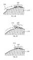
- FIG. 4Ashows a side view of a prior art covering for an electrical cord connection.
- FIG. 4Bshows a side view of a prior art covering for an electrical cord connection.
- FIG. 4Cshows a side view of a prior art covering for an electrical cord connection.
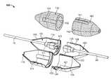
- FIGS. 1A-1Eshow a system 100 for covering an electrical cord connection, according to techniques of the present application.
- the system 100may include a first covering portion 110 , a second covering portion 120 , a first compression portion 130 , and a second compression portion 140 .
- the covering portions 110 , 120may be plastic.
- the covering portions 110 , 120may have a funnel-like shape.
- the compression portions 130 , 140may be foam and may have a funnel-like shape.
- the first covering portion 110may have an interior region, a cable aperture, a plug aperture, and a mating portion 113 proximate to the plug aperture.
- the interior regionmay house a portion of a cable 10 and a plug 11 of a first electrical cord.
- the cable aperturemay accommodate the cable 11 of the first electrical cord.
- the plug aperturemay be arranged to permit the plug 11 of the first electrical cord to mate with a plug 21 of a second electrical cord.
- the first covering portion 110may also have a hinge 112 (for example, a living hinge), a sealing ridge 115 , a keyway 111 , and a securing portion 114 .
- references to components or portions of the first covering portion 110may refer to one or more of such components or portions (for example, hinge 112 , sealing ridge 115 , keyway 111 , and securing portion 114 ).
- the hinge 112 and securing portion 114may allow the first covering portion 110 to be shaped as a clam shell with two casing halves.
- the securing portion 114may allow the two casing halves to securely open and close to seal the sealing ridge 115 .
- the securing portion 114may be integrated into the first covering portion 110 and may include snap locks.
- the second covering portion 120may have an interior region, a cable aperture, a plug aperture, and a mating portion 123 proximate to the plug aperture.
- the interior regionmay house a portion of a cable 20 and a plug 21 of a second electrical cord.
- the cable aperturemay accommodate the cable 20 of the second electrical cord.
- the plug aperturemay be arranged to permit the plug 21 of the second electrical cord to mate with a plug 11 of the first electrical cord.
- the second covering portion 120may also have a hinge 122 (for example, a living hinge), a sealing ridge 125 , a keyway 121 , and a securing portion 124 .
- references to components or portions of the second covering portion 120may refer to one or more of such components or portions (for example, hinge 122 , sealing ridge 125 , keyway 121 , and securing portion 124 ).
- the hinge 122 and securing portion 124may allow the second covering portion 120 to be shaped as a clam shell with two casing halves.
- the securing portion 124may allow the two casing halves to securely open and close to seal the sealing ridge 125 .
- the securing portion 124may be integrated into the second covering portion 120 and may include snap locks.
- the first compression portion 130may include an access slit 132 and a keyway 131 .
- the first compression portion 130may nest (at least partially) within the interior region of the first covering portion 110 .
- the first compression portion 130may surround the portion of the cable 10 and the plug 11 of the first electrical cord accommodated by the interior region of the first covering portion 110 .
- the access slit 132may facilitate this surrounding arrangement by allowing the electrical cord 10 to pass through a lateral wall of the first compression portion 130 .
- the second compression portion 140may include an access slit 142 and a keyway 141 .
- the second compression portion 140may nest (at least partially) within the interior region of the second covering portion 120 .
- the second compression portion 140may surround the portion of the cable 20 and the plug 21 of the second electrical cord accommodated by the interior region of the second covering portion 120 .
- the access slit 142may facilitate this surrounding arrangement by allowing the electrical cord 20 to pass through a lateral wall of the second compression portion 140 .
- the compression portions 130 , 140may include foam such as closed-cell foam, which may inhibit or prevent the absorption of liquids such as water.
- the foammay repel water, which may bead once hitting the foam and then roll off of the foam. Due to the compressibility of the foam, the compression portions 130 , 140 may be self-adjusting, thereby facilitating the formation of seals around different size cords or wires, such as 14 , 16 , 18 , 20 , 22 , or 24 gauge wires or cords.
- FIG. 1Dshows a cross-sectional view of the system 100 before the covering portions 110 , 120 are mated.
- FIG. 1Eshows a cross-sectional view of the system 100 after the covering portions 110 , 120 are mated.
- the first compression portion 130may compress (as illustrated by the arrows in FIG. 1E ) and fill in voids in the interior region of the first covering portion 110 (for example, near the cable aperture). This compression (for example, radial compression) may also form seals at the cable aperture and at the access slit 132 .
- the second compression portion 140may compress and fill in voids in the interior region of the second covering portion 120 . This compression may also form seals at the cable aperture and at the access slit 142 .
- the first and second compression portions 130 , 140may compress against each other and a seal may be formed at the plug apertures and around the mated plugs 11 , 21 .
- the mating portions 113 , 123may mate by screwing (for example, 1 ⁇ 4 turn).
- the compression portions 130 , 140may be slightly larger than the respective covering portions 110 , 120 . This may facilitate compression once the first and second covering portions 110 , 120 are mated.
- the keyways 111 , 121 of the covering portions 110 , 120may also facilitate preventing moisture from seeping into the electrical connection between the plugs 11 , 21 .
- keyways 131 , 141may be employed in order to have the compression portions 130 , 140 nest in a particular orientation to the respective covering portions 110 , 120 .
- the compression portions 130 , 140may have keyways 131 , 141 that match the respective keyways 111 , 121 on the covering portions 110 , 120 .
- the slits 132may be positioned or rotated away from the sealing ridges 115 of the covering portions 110 , 120 .
- the keyways 111 , 121 , 131 , 141may also provide an indicator whether the covering portions 110 , 120 are mated or not.
- the system shown in FIGS. 1A-1Emay be used in the following manner.
- the cables 10 , 20 and plugs 11 , 21 of the first/second electrical cordsare placed in the respective first/second compression portions 130 , 140 . This is facilitated by the slits 132 , 142 .
- the first/second compression portions 130 , 140are then placed in the respective first/second covering portions 110 , 120 .
- the keyways 111 , 121 , 131 , 141 of the compression portions 130 , 140 and the covering portions 110 , 120maintain a desirable orientation to prevent the slits 132 , 142 from lining up with the sealing ridges 115 , 125 .
- the covering portions 110 , 120are closed and secured around the compression portions 130 , 140 .
- the covering portions 110 , 120are screwed together. This causes the compression portions 130 , 140 to compress.
- the compressioncauses various seals to be made—for example, seals around the cable apertures, plug apertures, sealing ridges, etc. Additionally, the compression portions 130 , 140 compress against each other causing an additional compression seal.
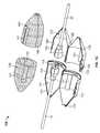
- FIGS. 2A-2Eshow a system 200 for covering an electrical cord connection, according to techniques of the present application.
- the system 200may include a first covering portion 210 , a second covering portion 220 , a compression portion 230 .
- the covering portions 210 , 220may be plastic.
- the covering portions 210 , 220may have a funnel-like shape.
- the compression portion 230may be foam and may have one or more funnel-like shapes.
- the compression portion 230may be formed of two compression portions, such compression portions 130 , 140 .
- the first covering portion 210may have an interior region, a cable aperture, a plug aperture, and a mating portion 213 proximate to the plug aperture.
- the interior regionmay house a portion of a cable 10 and a plug 11 of a first electrical cord.
- the cable aperturemay accommodate the cable 10 of the first electrical cord.
- the plug aperturemay be arranged to permit the plug 11 of the first electrical cord to mate with a plug 21 of a second electrical cord.
- the first covering portion 210may also have a hinge 212 (for example, a living hinge), a sealing ridge 217 , and a securing portion 214 .
- references to components or portions of the first covering portion 210may refer to one or more of such components or portions (for example, hinge 212 , sealing ridge 217 , and securing portion 214 ).
- the hinge 212 and securing portion 214may allow the first covering portion 210 to be shaped as a clam shell with two casing halves.
- the securing portion 214may allow the two casing halves to securely open and close to seal the sealing ridge 217 .
- the securing portion 214may be integrated into the first covering portion 210 and may include snap locks.
- the second covering portion 220may have an interior region, a cable aperture, a plug aperture, and a mating portion 223 proximate to the plug aperture.
- the interior regionmay house a portion of a cable 20 and a plug 21 of a second electrical cord.
- the cable aperturemay accommodate the cable 20 of the second electrical cord.
- the plug aperturemay be arranged to permit the plug 21 of the second electrical cord to mate with a plug 11 of the first electrical cord.
- the second covering portion 220may also have a hinge 222 (for example, a living hinge) a sealing ridge 227 , and a securing portion 224 .
- references to components or portions of the second covering portion 220may refer to one or more of such components or portions (for example, hinge 222 , sealing ridge 227 , and securing portion 224 ).
- the hinge 222 and securing portion 224may allow the second covering portion 220 to be shaped as a clam shell with two casing halves.
- the securing portion 224may allow the two casing halves to securely open and close to seal the sealing ridge 227 .
- the securing portion 224may be integrated into the second covering portion 220 and may include snap locks.
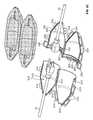
- the first and second covering portions 210 , 220may include other connectors, such as radial lock(s).
- the radial locksmay include nubs 215 and mating tabs 225 (for example, four pairs of nubs 215 and tabs 225 ). While the nubs 215 are depicted on the first covering portion 210 and the mating tabs 225 are depicted on the second covering portion 220 , the reverse may also be possible.
- the nubs 215 and tabs 225may mate as a result of twisting and mating the covering portions 210 , 220 .
- a given nub 215may force a tab 225 outwardly away from the covering portion 220 .
- the tab 225may then become compressed.
- the tab 225may have an opening that receives the nub 215 .
- the tab 225may at least partially decompress, thereby “locking” the nub 215 and tab 225 .
- the height of the nub 215may be approximately the same as the height of the tab 225 .
- the nub 215may have a side with a shallow slope and a side with a steep slope.
- the shallow slopemay be “shallow” in that it may be shallower than the steep slope.
- the steep slopemay be “steep” in that it may be steeper than the shallower slope.
- the shallower slope side of the nub 215may be employed to compress the tab 225 when going from an unlocked to a locked state. This may reduce the amount of torque needed to lock the radial locking system by causing the tab 225 to more gradually compress as the nub 215 moves underneath the tab 225 .
- the steeper slope side of the nub 215may be employed to compress the tab 225 when going from a locked to an unlocked state. This may increase the amount of torque needed to unlock the radial locking system by causing the tab 225 to more rapidly compress as the nub 215 moves underneath the tab 225 .
- the radial lock(s) 215 , 225may provide for a more robust connection between the covering portions 210 , 220 and may also provide feedback to a user that the covering portions 210 , 220 have been connected.
- the radial locks 215 , 225may also discourage over-tightening of the covering portions 210 , 220 .
- the radial locks 215 , 225may also provide structural support to prevent the covering portions 210 , 220 from opening, disconnecting, or becoming damaged as a result of certain torqueing events.
- four pairs of radial locks 215 , 225may be provided at approximately 90° from each other, thereby creating two opposing sets of pairs at approximately 180° from each other. This configuration may provide additional strength by matching a pulling force on one of the locks against a pushing force of the other lock 180° away.
- the first or second covering portions 210 , 220may include a hanger 226 (shown as part of second covering portion 220 ).
- the hanger 226may facilitate hanging or attachment of the system 200 to other items or structures (for example, a nail or twine).
- the compression portion 230may accommodate the plugs and cords 10 , 11 , 20 , 21 , for example, with a hollow interior region.
- the compression portion 230may nest (at least partially) within the interior regions of the covering portions 210 , 220 .
- the compression portion 230may surround the portion of the cable 10 and the plug 11 of the first electrical cord accommodated by the interior region of the first covering portion 110 .
- the compression portion 230may be formed of two parts, such as a left and right part similar compression portion 130 , 140 .
- the compression portion 230may be formed of a top and bottom part, either separate or connected by a hinge as shown in FIG. 2C . Such a hinge may be a living hinge, and the compression portion 230 may be formed from one piece of compressible material.
- the compression portion 230may include foam such as closed-cell foam, which may inhibit or prevent the absorption of liquids such as water.
- the foammay repel water, which may bead once hitting the foam and then roll off of the foam. Due to the compressibility of the foam, the compression portion 230 may be self-adjusting, thereby facilitating the formation of seals around different size cords or wires, such as 14, 16, 18, 20, 22, or 24 gauge wires or cords.
- the compression portion 230may have a density of approximately 2 lbs/ft 3 and a tensile strength of approximately 35 psi.
- the compression portion 230may have an elongation of approximately 160% and a tear resistance of approximately 7.
- the compression portion 230may have compression strengths as follows: approximately 4.5 psi at 10% deflection; approximately 7 psi at 25% deflection, approximately 11 psi at 40% deflection, and approximately 15 psi at 50% deflection.
- the compression portion 230may have a compression set of approximately 16% and a thermal stability of less than approximately 3% change over 24 hours at 158° F. Such specifications may be determined according to the ASTM D3575 standard.
- the hollow interior region of the compression portion 230may have a plug-accommodating hollow region that accommodates the plugs 11 , 21 and cord-accommodating hollow regions (for example, two crevices), which accommodate portions of the cords 10 , 20 .
- the cord-accommodating hollow regionsmay each extend from the plug-accommodating hollow region toward different ends (for example, opposite ends) of the compression portion 230 .
- the cord-accommodating regionsmay not extend all of the distance to the ends.
- FIG. 2Dshows a cross-sectional view of the system 200 before the covering portions 210 , 220 are mated.
- FIG. 2Eshows a cross-sectional view of the system 200 after the covering portions 210 , 220 are mated.
- the compression portion 230may compress (as illustrated by the arrows in FIG. 2E ) and fill in voids in the interior regions of the covering portions 210 , 220 (for example, near the cable apertures). This compression (for example, radial compression) may also form seals at the cable apertures.
- the first and second covering portions 210 , 220may mate through mating portions 213 , 223 (for example, complimentary screw threads) which screw together (for example, 1 ⁇ 4 turn). As the covering portions 210 , 220 are connected they may exert a radial compression force upon the compression portion 230 causing it to fill in the voids around the cables 10 , 20 and the other openings along the compression portion 230 resulting in a substantially water or weather resistant seal around the electrical connection between the plugs 11 , 21 .
- system 200may employ keyways, such as those shown in system 100 .
- various features in either system 100 or 200may be interchangeable or equally applicable to the other of system 100 or 200 .
- a hangersuch as hanger 226 may also be employed in system 100 .
- the system 200 shown in FIGS. 2A-2Emay be used in the following manner.
- the compression portion 230has a top and bottom portion and a living clam shell hinge. The top portion and the bottom portion are opened with respect to each other, thereby revealing the hollow interior region.
- the cables 10 , 20 and plugs 11 , 21 of the first and second electrical cordsare placed in the compression portion 230 .
- the compression portion 230is then placed in the first covering portion 210 .
- the first covering portion 210is then mated with the second covering portion 220 with their respective threads 213 , 223 by turning the covering portions 210 , 220 1 ⁇ 4 turn with respect to each other.
- four nubs 215 on the first covering portion 210force outwardly (along a radial direction) four corresponding tabs 225 on the second covering portion 220 .
- the tabs 225become compressed until the nubs 215 enter corresponding openings in the tabs 225 .
- the tabs 225decompress, thereby locking the nubs 215 and tabs 225 (and thereby locking the first covering portion 210 and the second covering portion 220 ).
Landscapes
- Connector Housings Or Holding Contact Members (AREA)
- Details Of Connecting Devices For Male And Female Coupling (AREA)
- Connections By Means Of Piercing Elements, Nuts, Or Screws (AREA)
Abstract
Description
Claims (13)
Priority Applications (8)
| Application Number | Priority Date | Filing Date | Title |
|---|---|---|---|
| US13/597,590US8702440B2 (en) | 2011-08-29 | 2012-08-29 | Electrical cord connection covering techniques |
| US13/772,859US8870587B2 (en) | 2011-08-29 | 2013-02-21 | Electrical cord connection covering techniques |
| US29/483,894USD753606S1 (en) | 2012-08-29 | 2014-03-04 | Electrical cord connection cover |
| US14/864,040US20160013579A1 (en) | 2011-08-29 | 2015-09-24 | Electrical cord connection covering techniques |
| US15/137,131US9413101B1 (en) | 2011-08-29 | 2016-04-25 | Electrical cord connection covering techniques |
| US15/158,842US9653837B2 (en) | 2011-08-29 | 2016-05-19 | Electrical cord connection covering techniques |
| US15/359,807US20170331219A1 (en) | 2012-08-29 | 2016-11-23 | Electrical cord connection covering techniques |
| US15/461,103US20170187145A1 (en) | 2012-08-29 | 2017-03-16 | Electrical cord connection covering techniques |
Applications Claiming Priority (2)
| Application Number | Priority Date | Filing Date | Title |
|---|---|---|---|
| US201161528456P | 2011-08-29 | 2011-08-29 | |
| US13/597,590US8702440B2 (en) | 2011-08-29 | 2012-08-29 | Electrical cord connection covering techniques |
Related Child Applications (1)
| Application Number | Title | Priority Date | Filing Date |
|---|---|---|---|
| US13/772,859Continuation-In-PartUS8870587B2 (en) | 2011-08-29 | 2013-02-21 | Electrical cord connection covering techniques |
Publications (2)
| Publication Number | Publication Date |
|---|---|
| US20130052890A1 US20130052890A1 (en) | 2013-02-28 |
| US8702440B2true US8702440B2 (en) | 2014-04-22 |
Family
ID=47744356
Family Applications (1)
| Application Number | Title | Priority Date | Filing Date |
|---|---|---|---|
| US13/597,590Active2032-09-21US8702440B2 (en) | 2011-08-29 | 2012-08-29 | Electrical cord connection covering techniques |
Country Status (4)
| Country | Link |
|---|---|
| US (1) | US8702440B2 (en) |
| CA (1) | CA2844133C (en) |
| MX (1) | MX2014002286A (en) |
| WO (1) | WO2013033161A1 (en) |
Cited By (16)
| Publication number | Priority date | Publication date | Assignee | Title |
|---|---|---|---|---|
| US20140370744A1 (en)* | 2012-05-18 | 2014-12-18 | Kostal Kontakt Systeme Gmbh | Plug-Connector Housing and Plug Connector |
| US20150333452A1 (en)* | 2014-05-14 | 2015-11-19 | Commscope Technologies Llc | Rf-isolating sealing enclosure and interconnection junctions protected thereby |
| US20160064883A1 (en)* | 2014-08-28 | 2016-03-03 | Tom Macauda | Electrical Power Cord with Supplemental Socket |
| US20160197434A1 (en)* | 2015-01-05 | 2016-07-07 | Echostar Technologies L.L.C. | Flat ethernet cables and associated systems, devices, and methods |
| US9407032B1 (en)* | 2015-07-30 | 2016-08-02 | Idis Co., Ltd. | Waterproof device for connector joint |
| US20160268723A1 (en)* | 2013-10-21 | 2016-09-15 | Ampfibian Holdings Pty Ltd | Closure seal for electrical adaptor |
| US20160329132A1 (en)* | 2015-05-04 | 2016-11-10 | Midwest Innovative Products, Llc | Electrical cord connection covering techniques |
| USD821988S1 (en)* | 2017-11-22 | 2018-07-03 | Yi-Fong Chang | Wire housing protector |
| USD848376S1 (en)* | 2017-05-29 | 2019-05-14 | Fsp Holdings Pty Ltd. | Cable plug protector assembly |
| USD852152S1 (en)* | 2018-03-29 | 2019-06-25 | Molex, Llc | Protective casing for cables, wires, and the like |
| USD861622S1 (en)* | 2018-03-29 | 2019-10-01 | Molex, Llc | Protective casing for cables, wires, and the like |
| US10468860B2 (en)* | 2016-10-07 | 2019-11-05 | Norman R. Byrne | Rugged weather resistant power distribution |
| USD865692S1 (en) | 2018-03-29 | 2019-11-05 | Molex, Llc | Cable harness with protective casing |
| US11283248B2 (en) | 2018-03-29 | 2022-03-22 | Molex, Llc | Spine for protecting and supporting a cable harness |
| USD1001076S1 (en)* | 2023-02-14 | 2023-10-10 | Phillip E Shuyler | Extension cord connector |
| USD1009804S1 (en)* | 2020-06-04 | 2024-01-02 | United States Goverment as represented by the Department of Veterans Affairs | Fuse cover |
Families Citing this family (6)
| Publication number | Priority date | Publication date | Assignee | Title |
|---|---|---|---|---|
| US8870587B2 (en)* | 2011-08-29 | 2014-10-28 | Midwest Innovative Products, Llc | Electrical cord connection covering techniques |
| MX2014002286A (en)* | 2011-08-29 | 2014-07-24 | Midwest Innovative Products Llc | Electrical cord connection covering techniques. |
| JP5915939B2 (en)* | 2013-01-16 | 2016-05-11 | 住友電装株式会社 | Grommet protective member and electric wire connecting device |
| USD776623S1 (en) | 2015-04-28 | 2017-01-17 | Sam Jenkins | Extension cord cover |
| CN107579384A (en)* | 2017-08-30 | 2018-01-12 | 绵阳鹏志远科技有限公司 | The socket dust guard of night illumination is provided |
| CN112467455A (en)* | 2020-11-19 | 2021-03-09 | 麦克传感器股份有限公司 | High waterproof plastic watertight connector |
Citations (12)
| Publication number | Priority date | Publication date | Assignee | Title |
|---|---|---|---|---|
| US3344393A (en) | 1965-08-13 | 1967-09-26 | Howard R Hendee | Connector housing |
| US4066321A (en) | 1976-01-17 | 1978-01-03 | Amp Incorporated | Electrical connector |
| US5217387A (en)* | 1992-04-28 | 1993-06-08 | Hull Harold L | Water resistant extension cord connector housing |
| US5259782A (en) | 1992-06-26 | 1993-11-09 | Giffin Kevin H | Electrical connector jacket |
| US6250946B1 (en) | 2000-05-23 | 2001-06-26 | Don E. Tardy | Extension cord plug cover |
| USD466088S1 (en)* | 2002-02-15 | 2002-11-26 | Barrett E Saben | Electric cord connector |
| US20050147361A1 (en)* | 2003-12-29 | 2005-07-07 | Hovland Jeffrey S. | Telecommunications connector protective device |
| US7189100B1 (en)* | 2005-02-18 | 2007-03-13 | Colbourne Jerome G | Cord retaining housing and method |
| US7465182B1 (en) | 2007-11-30 | 2008-12-16 | Mcdonald Michael | Electrical cord connector assembly |
| US7553181B1 (en)* | 2008-04-17 | 2009-06-30 | Van Dalinda Iii William R | Cord connection device |
| US20130052890A1 (en)* | 2011-08-29 | 2013-02-28 | Bryan Nooner | Electrical cord connection covering techniques |
| US20130165002A1 (en)* | 2011-08-29 | 2013-06-27 | Midwest Innovative Products, Llc | Electrical cord connection covering techniques |
- 2012
- 2012-08-29MXMX2014002286Apatent/MX2014002286A/enunknown
- 2012-08-29WOPCT/US2012/052795patent/WO2013033161A1/enactiveApplication Filing
- 2012-08-29USUS13/597,590patent/US8702440B2/enactiveActive
- 2012-08-29CACA2844133Apatent/CA2844133C/ennot_activeExpired - Fee Related
Patent Citations (12)
| Publication number | Priority date | Publication date | Assignee | Title |
|---|---|---|---|---|
| US3344393A (en) | 1965-08-13 | 1967-09-26 | Howard R Hendee | Connector housing |
| US4066321A (en) | 1976-01-17 | 1978-01-03 | Amp Incorporated | Electrical connector |
| US5217387A (en)* | 1992-04-28 | 1993-06-08 | Hull Harold L | Water resistant extension cord connector housing |
| US5259782A (en) | 1992-06-26 | 1993-11-09 | Giffin Kevin H | Electrical connector jacket |
| US6250946B1 (en) | 2000-05-23 | 2001-06-26 | Don E. Tardy | Extension cord plug cover |
| USD466088S1 (en)* | 2002-02-15 | 2002-11-26 | Barrett E Saben | Electric cord connector |
| US20050147361A1 (en)* | 2003-12-29 | 2005-07-07 | Hovland Jeffrey S. | Telecommunications connector protective device |
| US7189100B1 (en)* | 2005-02-18 | 2007-03-13 | Colbourne Jerome G | Cord retaining housing and method |
| US7465182B1 (en) | 2007-11-30 | 2008-12-16 | Mcdonald Michael | Electrical cord connector assembly |
| US7553181B1 (en)* | 2008-04-17 | 2009-06-30 | Van Dalinda Iii William R | Cord connection device |
| US20130052890A1 (en)* | 2011-08-29 | 2013-02-28 | Bryan Nooner | Electrical cord connection covering techniques |
| US20130165002A1 (en)* | 2011-08-29 | 2013-06-27 | Midwest Innovative Products, Llc | Electrical cord connection covering techniques |
Non-Patent Citations (1)
| Title |
|---|
| International Search Report and the Written Opinion of the International Searching Authority (PCT), 12 pgs., Nov. 14, 2012. |
Cited By (24)
| Publication number | Priority date | Publication date | Assignee | Title |
|---|---|---|---|---|
| US9209553B2 (en)* | 2012-05-18 | 2015-12-08 | Kostal Kontakt Systeme Gmbh | Plug-connector housing and plug connector |
| US20140370744A1 (en)* | 2012-05-18 | 2014-12-18 | Kostal Kontakt Systeme Gmbh | Plug-Connector Housing and Plug Connector |
| US9601865B2 (en)* | 2013-10-21 | 2017-03-21 | Ampfibian Holdings Pty. Ltd | Closure seal for electrical adaptor |
| US20160268723A1 (en)* | 2013-10-21 | 2016-09-15 | Ampfibian Holdings Pty Ltd | Closure seal for electrical adaptor |
| US20150333452A1 (en)* | 2014-05-14 | 2015-11-19 | Commscope Technologies Llc | Rf-isolating sealing enclosure and interconnection junctions protected thereby |
| US9653852B2 (en)* | 2014-05-14 | 2017-05-16 | Commscope Technologies Llc | RF-isolating sealing enclosure and interconnection junctions protected thereby |
| US20160064883A1 (en)* | 2014-08-28 | 2016-03-03 | Tom Macauda | Electrical Power Cord with Supplemental Socket |
| US9463564B2 (en)* | 2014-08-28 | 2016-10-11 | Tom Macauda | Electrical power cord with supplemental socket |
| US9941623B2 (en)* | 2015-01-05 | 2018-04-10 | Echostar Technologies International Corporation | Flat ethernet cables and associated systems, devices, and methods |
| US20160197434A1 (en)* | 2015-01-05 | 2016-07-07 | Echostar Technologies L.L.C. | Flat ethernet cables and associated systems, devices, and methods |
| US10164416B2 (en) | 2015-05-04 | 2018-12-25 | Midwest Innovative Products, Llc | Electrical cord connection covering techniques |
| US9742171B2 (en)* | 2015-05-04 | 2017-08-22 | Midwest Innovative Products, Llc | Electrical cord connection covering techniques |
| US20160329132A1 (en)* | 2015-05-04 | 2016-11-10 | Midwest Innovative Products, Llc | Electrical cord connection covering techniques |
| US9407032B1 (en)* | 2015-07-30 | 2016-08-02 | Idis Co., Ltd. | Waterproof device for connector joint |
| US10468860B2 (en)* | 2016-10-07 | 2019-11-05 | Norman R. Byrne | Rugged weather resistant power distribution |
| USD848376S1 (en)* | 2017-05-29 | 2019-05-14 | Fsp Holdings Pty Ltd. | Cable plug protector assembly |
| USD821988S1 (en)* | 2017-11-22 | 2018-07-03 | Yi-Fong Chang | Wire housing protector |
| USD852152S1 (en)* | 2018-03-29 | 2019-06-25 | Molex, Llc | Protective casing for cables, wires, and the like |
| USD861622S1 (en)* | 2018-03-29 | 2019-10-01 | Molex, Llc | Protective casing for cables, wires, and the like |
| USD865692S1 (en) | 2018-03-29 | 2019-11-05 | Molex, Llc | Cable harness with protective casing |
| US11283248B2 (en) | 2018-03-29 | 2022-03-22 | Molex, Llc | Spine for protecting and supporting a cable harness |
| USD1009804S1 (en)* | 2020-06-04 | 2024-01-02 | United States Goverment as represented by the Department of Veterans Affairs | Fuse cover |
| USD1001076S1 (en)* | 2023-02-14 | 2023-10-10 | Phillip E Shuyler | Extension cord connector |
| USD1007429S1 (en)* | 2023-02-14 | 2023-12-12 | Phillip E Shuyler | Extension cord connector |
Also Published As
| Publication number | Publication date |
|---|---|
| CA2844133A1 (en) | 2013-03-07 |
| MX2014002286A (en) | 2014-07-24 |
| CA2844133C (en) | 2016-06-28 |
| WO2013033161A1 (en) | 2013-03-07 |
| US20130052890A1 (en) | 2013-02-28 |
Similar Documents
| Publication | Publication Date | Title |
|---|---|---|
| US8702440B2 (en) | Electrical cord connection covering techniques | |
| US9413101B1 (en) | Electrical cord connection covering techniques | |
| US20170187145A1 (en) | Electrical cord connection covering techniques | |
| US7285725B1 (en) | Weatherproof and restraining apparatus for electrical plugs | |
| US7109416B1 (en) | Electrical wiring access box | |
| CA2175425C (en) | Closure cap with gasket for electrical connector housing | |
| US9742171B2 (en) | Electrical cord connection covering techniques | |
| US10559907B1 (en) | Electrical plug connector | |
| US5104331A (en) | Damage resistant latching electrical connector | |
| US3200989A (en) | Locking weatherproof cover attachment for electrical outlet box | |
| US10079481B2 (en) | Weatherproof electrical box assembly | |
| US9197005B2 (en) | Waterproof cover for an electrical plug | |
| US5494457A (en) | Snagless strain relief | |
| WO2007143603A2 (en) | Electrical connector with plug tether assembly and related methods | |
| US10923851B2 (en) | Outdoor electrical plug and socket cover | |
| KR100960653B1 (en) | Distribution box for preventing electrical accidents of house | |
| CN102403609B (en) | Tool-releasable solar power connector | |
| JP2001515697A (en) | External ground insulation connector for cable connection closure | |
| KR100611574B1 (en) | Outlet plug and plug with waterproof structure | |
| CN2935509Y (en) | Cable connection insulator | |
| US8197278B2 (en) | Locking cord connector assembly | |
| KR200451607Y1 (en) | Cap for battery terminal | |
| US9531107B1 (en) | Tamper resistant power tap | |
| US4911654A (en) | Device for preventing disconnection of or damage to electrical connectors | |
| US6969279B1 (en) | Exterior connection weather seal |
Legal Events
| Date | Code | Title | Description |
|---|---|---|---|
| AS | Assignment | Owner name:MIDWEST INNOVATIVE PRODUCTS, LLC, ILLINOIS Free format text:ASSIGNMENT OF ASSIGNORS INTEREST;ASSIGNORS:NOONER, BRYAN;ZAJESKI, ROBERT;REEL/FRAME:029062/0217 Effective date:20120919 | |
| STCF | Information on status: patent grant | Free format text:PATENTED CASE | |
| AS | Assignment | Owner name:MIDWEST INNOVATIVE PRODUCTS, LLC, ILLINOIS Free format text:CHANGE OF ASSIGNEE ADDRESS;ASSIGNOR:MIDWEST INNOVATIVE PRODUCTS, LLC;REEL/FRAME:038605/0102 Effective date:20160422 | |
| AS | Assignment | Owner name:AMBASSADOR CAPITAL, LLC, INDIANA Free format text:SECURITY INTEREST;ASSIGNOR:MIDWEST INNOVATIVE PRODUCTS, LLC;REEL/FRAME:039012/0373 Effective date:20140325 | |
| AS | Assignment | Owner name:AMBASSADOR CAPITAL, LLC, INDIANA Free format text:SECURITY INTEREST;ASSIGNOR:MIDWEST INNOVATIVE PRODUCTS, LLC;REEL/FRAME:039214/0621 Effective date:20140829 | |
| AS | Assignment | Owner name:MIDWEST INNOVATIVE PRODUCTS, LLC, ILLINOIS Free format text:RELEASE BY SECURED PARTY;ASSIGNOR:AMBASSADOR CAPITAL, LLC;REEL/FRAME:042089/0005 Effective date:20170420 | |
| AS | Assignment | Owner name:CHEMICAL BANK, MICHIGAN Free format text:SECURITY INTEREST;ASSIGNOR:MIDWEST INNOVATIVE PRODUCTS, LLC;REEL/FRAME:042243/0703 Effective date:20170428 | |
| MAFP | Maintenance fee payment | Free format text:PAYMENT OF MAINTENANCE FEE, 4TH YR, SMALL ENTITY (ORIGINAL EVENT CODE: M2551) Year of fee payment:4 | |
| AS | Assignment | Owner name:MERCANTILE BANK OF MICHIGAN, MICHIGAN Free format text:SECURITY INTEREST;ASSIGNOR:MIDWEST INNOVATIVE PRODUCTS, LLC;REEL/FRAME:056123/0030 Effective date:20210331 | |
| MAFP | Maintenance fee payment | Free format text:PAYMENT OF MAINTENANCE FEE, 8TH YR, SMALL ENTITY (ORIGINAL EVENT CODE: M2552); ENTITY STATUS OF PATENT OWNER: SMALL ENTITY Year of fee payment:8 | |
| AS | Assignment | Owner name:MIDWEST INNOVATIVE PRODUCTS, LLC, ILLINOIS Free format text:RELEASE BY SECURED PARTY;ASSIGNOR:MERCANTILE BANK OF MICHIGAN;REEL/FRAME:063759/0417 Effective date:20230510 | |
| AS | Assignment | Owner name:NORTHSTAR BANK, MICHIGAN Free format text:SECURITY INTEREST;ASSIGNOR:MIDWEST INNOVATIVE PRODUCTS, LLC;REEL/FRAME:063808/0105 Effective date:20230509 |