US8700198B2 - Implant components and methods - Google Patents
Implant components and methodsDownload PDFInfo
- Publication number
- US8700198B2 US8700198B2US13/156,245US201113156245AUS8700198B2US 8700198 B2US8700198 B2US 8700198B2US 201113156245 AUS201113156245 AUS 201113156245AUS 8700198 B2US8700198 B2US 8700198B2
- Authority
- US
- United States
- Prior art keywords
- implant
- porous
- mold
- particles
- protrusions
- Prior art date
- Legal status (The legal status is an assumption and is not a legal conclusion. Google has not performed a legal analysis and makes no representation as to the accuracy of the status listed.)
- Active
Links
Images


Classifications
- A—HUMAN NECESSITIES
- A61—MEDICAL OR VETERINARY SCIENCE; HYGIENE
- A61F—FILTERS IMPLANTABLE INTO BLOOD VESSELS; PROSTHESES; DEVICES PROVIDING PATENCY TO, OR PREVENTING COLLAPSING OF, TUBULAR STRUCTURES OF THE BODY, e.g. STENTS; ORTHOPAEDIC, NURSING OR CONTRACEPTIVE DEVICES; FOMENTATION; TREATMENT OR PROTECTION OF EYES OR EARS; BANDAGES, DRESSINGS OR ABSORBENT PADS; FIRST-AID KITS
- A61F2/00—Filters implantable into blood vessels; Prostheses, i.e. artificial substitutes or replacements for parts of the body; Appliances for connecting them with the body; Devices providing patency to, or preventing collapsing of, tubular structures of the body, e.g. stents
- A61F2/02—Prostheses implantable into the body
- A61F2/30—Joints
- A61F2/32—Joints for the hip
- A61F2/34—Acetabular cups
- A—HUMAN NECESSITIES
- A61—MEDICAL OR VETERINARY SCIENCE; HYGIENE
- A61B—DIAGNOSIS; SURGERY; IDENTIFICATION
- A61B17/00—Surgical instruments, devices or methods
- A61B17/56—Surgical instruments or methods for treatment of bones or joints; Devices specially adapted therefor
- A61B17/58—Surgical instruments or methods for treatment of bones or joints; Devices specially adapted therefor for osteosynthesis, e.g. bone plates, screws or setting implements
- A61B17/68—Internal fixation devices, including fasteners and spinal fixators, even if a part thereof projects from the skin
- A61B17/80—Cortical plates, i.e. bone plates; Instruments for holding or positioning cortical plates, or for compressing bones attached to cortical plates
- A61B17/8061—Cortical plates, i.e. bone plates; Instruments for holding or positioning cortical plates, or for compressing bones attached to cortical plates specially adapted for particular bones
- A61B17/8066—Cortical plates, i.e. bone plates; Instruments for holding or positioning cortical plates, or for compressing bones attached to cortical plates specially adapted for particular bones for pelvic reconstruction
- A—HUMAN NECESSITIES
- A61—MEDICAL OR VETERINARY SCIENCE; HYGIENE
- A61F—FILTERS IMPLANTABLE INTO BLOOD VESSELS; PROSTHESES; DEVICES PROVIDING PATENCY TO, OR PREVENTING COLLAPSING OF, TUBULAR STRUCTURES OF THE BODY, e.g. STENTS; ORTHOPAEDIC, NURSING OR CONTRACEPTIVE DEVICES; FOMENTATION; TREATMENT OR PROTECTION OF EYES OR EARS; BANDAGES, DRESSINGS OR ABSORBENT PADS; FIRST-AID KITS
- A61F2/00—Filters implantable into blood vessels; Prostheses, i.e. artificial substitutes or replacements for parts of the body; Appliances for connecting them with the body; Devices providing patency to, or preventing collapsing of, tubular structures of the body, e.g. stents
- A61F2/02—Prostheses implantable into the body
- A61F2/30—Joints
- A61F2/30721—Accessories
- A61F2/30734—Modular inserts, sleeves or augments, e.g. placed on proximal part of stem for fixation purposes or wedges for bridging a bone defect
- A—HUMAN NECESSITIES
- A61—MEDICAL OR VETERINARY SCIENCE; HYGIENE
- A61F—FILTERS IMPLANTABLE INTO BLOOD VESSELS; PROSTHESES; DEVICES PROVIDING PATENCY TO, OR PREVENTING COLLAPSING OF, TUBULAR STRUCTURES OF THE BODY, e.g. STENTS; ORTHOPAEDIC, NURSING OR CONTRACEPTIVE DEVICES; FOMENTATION; TREATMENT OR PROTECTION OF EYES OR EARS; BANDAGES, DRESSINGS OR ABSORBENT PADS; FIRST-AID KITS
- A61F2/00—Filters implantable into blood vessels; Prostheses, i.e. artificial substitutes or replacements for parts of the body; Appliances for connecting them with the body; Devices providing patency to, or preventing collapsing of, tubular structures of the body, e.g. stents
- A61F2/02—Prostheses implantable into the body
- A61F2/30—Joints
- A61F2/30721—Accessories
- A61F2/30749—Fixation appliances for connecting prostheses to the body
- A—HUMAN NECESSITIES
- A61—MEDICAL OR VETERINARY SCIENCE; HYGIENE
- A61F—FILTERS IMPLANTABLE INTO BLOOD VESSELS; PROSTHESES; DEVICES PROVIDING PATENCY TO, OR PREVENTING COLLAPSING OF, TUBULAR STRUCTURES OF THE BODY, e.g. STENTS; ORTHOPAEDIC, NURSING OR CONTRACEPTIVE DEVICES; FOMENTATION; TREATMENT OR PROTECTION OF EYES OR EARS; BANDAGES, DRESSINGS OR ABSORBENT PADS; FIRST-AID KITS
- A61F2/00—Filters implantable into blood vessels; Prostheses, i.e. artificial substitutes or replacements for parts of the body; Appliances for connecting them with the body; Devices providing patency to, or preventing collapsing of, tubular structures of the body, e.g. stents
- A61F2/02—Prostheses implantable into the body
- A61F2/30—Joints
- A61F2/30767—Special external or bone-contacting surface, e.g. coating for improving bone ingrowth
- A61F2/30771—Special external or bone-contacting surface, e.g. coating for improving bone ingrowth applied in original prostheses, e.g. holes or grooves
- A—HUMAN NECESSITIES
- A61—MEDICAL OR VETERINARY SCIENCE; HYGIENE
- A61F—FILTERS IMPLANTABLE INTO BLOOD VESSELS; PROSTHESES; DEVICES PROVIDING PATENCY TO, OR PREVENTING COLLAPSING OF, TUBULAR STRUCTURES OF THE BODY, e.g. STENTS; ORTHOPAEDIC, NURSING OR CONTRACEPTIVE DEVICES; FOMENTATION; TREATMENT OR PROTECTION OF EYES OR EARS; BANDAGES, DRESSINGS OR ABSORBENT PADS; FIRST-AID KITS
- A61F2/00—Filters implantable into blood vessels; Prostheses, i.e. artificial substitutes or replacements for parts of the body; Appliances for connecting them with the body; Devices providing patency to, or preventing collapsing of, tubular structures of the body, e.g. stents
- A61F2/02—Prostheses implantable into the body
- A61F2/30—Joints
- A61F2/3094—Designing or manufacturing processes
- A61F2/30965—Reinforcing the prosthesis by embedding particles or fibres during moulding or dipping
- A—HUMAN NECESSITIES
- A61—MEDICAL OR VETERINARY SCIENCE; HYGIENE
- A61F—FILTERS IMPLANTABLE INTO BLOOD VESSELS; PROSTHESES; DEVICES PROVIDING PATENCY TO, OR PREVENTING COLLAPSING OF, TUBULAR STRUCTURES OF THE BODY, e.g. STENTS; ORTHOPAEDIC, NURSING OR CONTRACEPTIVE DEVICES; FOMENTATION; TREATMENT OR PROTECTION OF EYES OR EARS; BANDAGES, DRESSINGS OR ABSORBENT PADS; FIRST-AID KITS
- A61F2/00—Filters implantable into blood vessels; Prostheses, i.e. artificial substitutes or replacements for parts of the body; Appliances for connecting them with the body; Devices providing patency to, or preventing collapsing of, tubular structures of the body, e.g. stents
- A61F2/02—Prostheses implantable into the body
- A61F2/30—Joints
- A61F2/46—Special tools for implanting artificial joints
- A61F2/4603—Special tools for implanting artificial joints for insertion or extraction of endoprosthetic joints or of accessories thereof
- A61F2/4609—Special tools for implanting artificial joints for insertion or extraction of endoprosthetic joints or of accessories thereof of acetabular cups
- G—PHYSICS
- G06—COMPUTING OR CALCULATING; COUNTING
- G06F—ELECTRIC DIGITAL DATA PROCESSING
- G06F9/00—Arrangements for program control, e.g. control units
- G06F9/06—Arrangements for program control, e.g. control units using stored programs, i.e. using an internal store of processing equipment to receive or retain programs
- G06F9/44—Arrangements for executing specific programs
- G06F9/455—Emulation; Interpretation; Software simulation, e.g. virtualisation or emulation of application or operating system execution engines
- G06F9/45533—Hypervisors; Virtual machine monitors
- A—HUMAN NECESSITIES
- A61—MEDICAL OR VETERINARY SCIENCE; HYGIENE
- A61B—DIAGNOSIS; SURGERY; IDENTIFICATION
- A61B17/00—Surgical instruments, devices or methods
- A61B17/56—Surgical instruments or methods for treatment of bones or joints; Devices specially adapted therefor
- A61B17/58—Surgical instruments or methods for treatment of bones or joints; Devices specially adapted therefor for osteosynthesis, e.g. bone plates, screws or setting implements
- A61B17/68—Internal fixation devices, including fasteners and spinal fixators, even if a part thereof projects from the skin
- A61B17/82—Internal fixation devices, including fasteners and spinal fixators, even if a part thereof projects from the skin for bone cerclage
- A—HUMAN NECESSITIES
- A61—MEDICAL OR VETERINARY SCIENCE; HYGIENE
- A61B—DIAGNOSIS; SURGERY; IDENTIFICATION
- A61B17/00—Surgical instruments, devices or methods
- A61B17/56—Surgical instruments or methods for treatment of bones or joints; Devices specially adapted therefor
- A61B17/58—Surgical instruments or methods for treatment of bones or joints; Devices specially adapted therefor for osteosynthesis, e.g. bone plates, screws or setting implements
- A61B17/68—Internal fixation devices, including fasteners and spinal fixators, even if a part thereof projects from the skin
- A61B17/84—Fasteners therefor or fasteners being internal fixation devices
- A61B17/86—Pins or screws or threaded wires; nuts therefor
- A61B17/866—Material or manufacture
- A—HUMAN NECESSITIES
- A61—MEDICAL OR VETERINARY SCIENCE; HYGIENE
- A61B—DIAGNOSIS; SURGERY; IDENTIFICATION
- A61B17/00—Surgical instruments, devices or methods
- A61B17/56—Surgical instruments or methods for treatment of bones or joints; Devices specially adapted therefor
- A61B17/58—Surgical instruments or methods for treatment of bones or joints; Devices specially adapted therefor for osteosynthesis, e.g. bone plates, screws or setting implements
- A61B17/68—Internal fixation devices, including fasteners and spinal fixators, even if a part thereof projects from the skin
- A61B17/84—Fasteners therefor or fasteners being internal fixation devices
- A61B17/86—Pins or screws or threaded wires; nuts therefor
- A61B17/8685—Pins or screws or threaded wires; nuts therefor comprising multiple separate parts
- A—HUMAN NECESSITIES
- A61—MEDICAL OR VETERINARY SCIENCE; HYGIENE
- A61F—FILTERS IMPLANTABLE INTO BLOOD VESSELS; PROSTHESES; DEVICES PROVIDING PATENCY TO, OR PREVENTING COLLAPSING OF, TUBULAR STRUCTURES OF THE BODY, e.g. STENTS; ORTHOPAEDIC, NURSING OR CONTRACEPTIVE DEVICES; FOMENTATION; TREATMENT OR PROTECTION OF EYES OR EARS; BANDAGES, DRESSINGS OR ABSORBENT PADS; FIRST-AID KITS
- A61F2/00—Filters implantable into blood vessels; Prostheses, i.e. artificial substitutes or replacements for parts of the body; Appliances for connecting them with the body; Devices providing patency to, or preventing collapsing of, tubular structures of the body, e.g. stents
- A61F2/02—Prostheses implantable into the body
- A61F2/30—Joints
- A61F2/30767—Special external or bone-contacting surface, e.g. coating for improving bone ingrowth
- A61F2/30907—Nets or sleeves applied to surface of prostheses or in cement
- A—HUMAN NECESSITIES
- A61—MEDICAL OR VETERINARY SCIENCE; HYGIENE
- A61F—FILTERS IMPLANTABLE INTO BLOOD VESSELS; PROSTHESES; DEVICES PROVIDING PATENCY TO, OR PREVENTING COLLAPSING OF, TUBULAR STRUCTURES OF THE BODY, e.g. STENTS; ORTHOPAEDIC, NURSING OR CONTRACEPTIVE DEVICES; FOMENTATION; TREATMENT OR PROTECTION OF EYES OR EARS; BANDAGES, DRESSINGS OR ABSORBENT PADS; FIRST-AID KITS
- A61F2/00—Filters implantable into blood vessels; Prostheses, i.e. artificial substitutes or replacements for parts of the body; Appliances for connecting them with the body; Devices providing patency to, or preventing collapsing of, tubular structures of the body, e.g. stents
- A61F2/02—Prostheses implantable into the body
- A61F2/30—Joints
- A61F2/3094—Designing or manufacturing processes
- A61F2/30942—Designing or manufacturing processes for designing or making customized prostheses, e.g. using templates, CT or NMR scans, finite-element analysis or CAD-CAM techniques
- A—HUMAN NECESSITIES
- A61—MEDICAL OR VETERINARY SCIENCE; HYGIENE
- A61F—FILTERS IMPLANTABLE INTO BLOOD VESSELS; PROSTHESES; DEVICES PROVIDING PATENCY TO, OR PREVENTING COLLAPSING OF, TUBULAR STRUCTURES OF THE BODY, e.g. STENTS; ORTHOPAEDIC, NURSING OR CONTRACEPTIVE DEVICES; FOMENTATION; TREATMENT OR PROTECTION OF EYES OR EARS; BANDAGES, DRESSINGS OR ABSORBENT PADS; FIRST-AID KITS
- A61F2/00—Filters implantable into blood vessels; Prostheses, i.e. artificial substitutes or replacements for parts of the body; Appliances for connecting them with the body; Devices providing patency to, or preventing collapsing of, tubular structures of the body, e.g. stents
- A61F2/02—Prostheses implantable into the body
- A61F2/30—Joints
- A61F2002/30001—Additional features of subject-matter classified in A61F2/28, A61F2/30 and subgroups thereof
- A61F2002/30003—Material related properties of the prosthesis or of a coating on the prosthesis
- A61F2002/30004—Material related properties of the prosthesis or of a coating on the prosthesis the prosthesis being made from materials having different values of a given property at different locations within the same prosthesis
- A61F2002/30011—Material related properties of the prosthesis or of a coating on the prosthesis the prosthesis being made from materials having different values of a given property at different locations within the same prosthesis differing in porosity
- A—HUMAN NECESSITIES
- A61—MEDICAL OR VETERINARY SCIENCE; HYGIENE
- A61F—FILTERS IMPLANTABLE INTO BLOOD VESSELS; PROSTHESES; DEVICES PROVIDING PATENCY TO, OR PREVENTING COLLAPSING OF, TUBULAR STRUCTURES OF THE BODY, e.g. STENTS; ORTHOPAEDIC, NURSING OR CONTRACEPTIVE DEVICES; FOMENTATION; TREATMENT OR PROTECTION OF EYES OR EARS; BANDAGES, DRESSINGS OR ABSORBENT PADS; FIRST-AID KITS
- A61F2/00—Filters implantable into blood vessels; Prostheses, i.e. artificial substitutes or replacements for parts of the body; Appliances for connecting them with the body; Devices providing patency to, or preventing collapsing of, tubular structures of the body, e.g. stents
- A61F2/02—Prostheses implantable into the body
- A61F2/30—Joints
- A61F2002/30001—Additional features of subject-matter classified in A61F2/28, A61F2/30 and subgroups thereof
- A61F2002/30108—Shapes
- A61F2002/3011—Cross-sections or two-dimensional shapes
- A61F2002/30159—Concave polygonal shapes
- A61F2002/30169—Pi-shaped
- A—HUMAN NECESSITIES
- A61—MEDICAL OR VETERINARY SCIENCE; HYGIENE
- A61F—FILTERS IMPLANTABLE INTO BLOOD VESSELS; PROSTHESES; DEVICES PROVIDING PATENCY TO, OR PREVENTING COLLAPSING OF, TUBULAR STRUCTURES OF THE BODY, e.g. STENTS; ORTHOPAEDIC, NURSING OR CONTRACEPTIVE DEVICES; FOMENTATION; TREATMENT OR PROTECTION OF EYES OR EARS; BANDAGES, DRESSINGS OR ABSORBENT PADS; FIRST-AID KITS
- A61F2/00—Filters implantable into blood vessels; Prostheses, i.e. artificial substitutes or replacements for parts of the body; Appliances for connecting them with the body; Devices providing patency to, or preventing collapsing of, tubular structures of the body, e.g. stents
- A61F2/02—Prostheses implantable into the body
- A61F2/30—Joints
- A61F2002/30001—Additional features of subject-matter classified in A61F2/28, A61F2/30 and subgroups thereof
- A61F2002/30108—Shapes
- A61F2002/3011—Cross-sections or two-dimensional shapes
- A61F2002/30182—Other shapes
- A61F2002/30189—E-shaped or epsilon-shaped
- A—HUMAN NECESSITIES
- A61—MEDICAL OR VETERINARY SCIENCE; HYGIENE
- A61F—FILTERS IMPLANTABLE INTO BLOOD VESSELS; PROSTHESES; DEVICES PROVIDING PATENCY TO, OR PREVENTING COLLAPSING OF, TUBULAR STRUCTURES OF THE BODY, e.g. STENTS; ORTHOPAEDIC, NURSING OR CONTRACEPTIVE DEVICES; FOMENTATION; TREATMENT OR PROTECTION OF EYES OR EARS; BANDAGES, DRESSINGS OR ABSORBENT PADS; FIRST-AID KITS
- A61F2/00—Filters implantable into blood vessels; Prostheses, i.e. artificial substitutes or replacements for parts of the body; Appliances for connecting them with the body; Devices providing patency to, or preventing collapsing of, tubular structures of the body, e.g. stents
- A61F2/02—Prostheses implantable into the body
- A61F2/30—Joints
- A61F2002/30001—Additional features of subject-matter classified in A61F2/28, A61F2/30 and subgroups thereof
- A61F2002/30316—The prosthesis having different structural features at different locations within the same prosthesis; Connections between prosthetic parts; Special structural features of bone or joint prostheses not otherwise provided for
- A61F2002/30317—The prosthesis having different structural features at different locations within the same prosthesis
- A61F2002/30326—The prosthesis having different structural features at different locations within the same prosthesis differing in height or in length
- A—HUMAN NECESSITIES
- A61—MEDICAL OR VETERINARY SCIENCE; HYGIENE
- A61F—FILTERS IMPLANTABLE INTO BLOOD VESSELS; PROSTHESES; DEVICES PROVIDING PATENCY TO, OR PREVENTING COLLAPSING OF, TUBULAR STRUCTURES OF THE BODY, e.g. STENTS; ORTHOPAEDIC, NURSING OR CONTRACEPTIVE DEVICES; FOMENTATION; TREATMENT OR PROTECTION OF EYES OR EARS; BANDAGES, DRESSINGS OR ABSORBENT PADS; FIRST-AID KITS
- A61F2/00—Filters implantable into blood vessels; Prostheses, i.e. artificial substitutes or replacements for parts of the body; Appliances for connecting them with the body; Devices providing patency to, or preventing collapsing of, tubular structures of the body, e.g. stents
- A61F2/02—Prostheses implantable into the body
- A61F2/30—Joints
- A61F2002/30001—Additional features of subject-matter classified in A61F2/28, A61F2/30 and subgroups thereof
- A61F2002/30316—The prosthesis having different structural features at different locations within the same prosthesis; Connections between prosthetic parts; Special structural features of bone or joint prostheses not otherwise provided for
- A61F2002/30329—Connections or couplings between prosthetic parts, e.g. between modular parts; Connecting elements
- A61F2002/30331—Connections or couplings between prosthetic parts, e.g. between modular parts; Connecting elements made by longitudinally pushing a protrusion into a complementarily-shaped recess, e.g. held by friction fit
- A—HUMAN NECESSITIES
- A61—MEDICAL OR VETERINARY SCIENCE; HYGIENE
- A61F—FILTERS IMPLANTABLE INTO BLOOD VESSELS; PROSTHESES; DEVICES PROVIDING PATENCY TO, OR PREVENTING COLLAPSING OF, TUBULAR STRUCTURES OF THE BODY, e.g. STENTS; ORTHOPAEDIC, NURSING OR CONTRACEPTIVE DEVICES; FOMENTATION; TREATMENT OR PROTECTION OF EYES OR EARS; BANDAGES, DRESSINGS OR ABSORBENT PADS; FIRST-AID KITS
- A61F2/00—Filters implantable into blood vessels; Prostheses, i.e. artificial substitutes or replacements for parts of the body; Appliances for connecting them with the body; Devices providing patency to, or preventing collapsing of, tubular structures of the body, e.g. stents
- A61F2/02—Prostheses implantable into the body
- A61F2/30—Joints
- A61F2002/30001—Additional features of subject-matter classified in A61F2/28, A61F2/30 and subgroups thereof
- A61F2002/30316—The prosthesis having different structural features at different locations within the same prosthesis; Connections between prosthetic parts; Special structural features of bone or joint prostheses not otherwise provided for
- A61F2002/30329—Connections or couplings between prosthetic parts, e.g. between modular parts; Connecting elements
- A61F2002/30383—Connections or couplings between prosthetic parts, e.g. between modular parts; Connecting elements made by laterally inserting a protrusion, e.g. a rib into a complementarily-shaped groove
- A61F2002/30387—Dovetail connection
- A—HUMAN NECESSITIES
- A61—MEDICAL OR VETERINARY SCIENCE; HYGIENE
- A61F—FILTERS IMPLANTABLE INTO BLOOD VESSELS; PROSTHESES; DEVICES PROVIDING PATENCY TO, OR PREVENTING COLLAPSING OF, TUBULAR STRUCTURES OF THE BODY, e.g. STENTS; ORTHOPAEDIC, NURSING OR CONTRACEPTIVE DEVICES; FOMENTATION; TREATMENT OR PROTECTION OF EYES OR EARS; BANDAGES, DRESSINGS OR ABSORBENT PADS; FIRST-AID KITS
- A61F2/00—Filters implantable into blood vessels; Prostheses, i.e. artificial substitutes or replacements for parts of the body; Appliances for connecting them with the body; Devices providing patency to, or preventing collapsing of, tubular structures of the body, e.g. stents
- A61F2/02—Prostheses implantable into the body
- A61F2/30—Joints
- A61F2002/30001—Additional features of subject-matter classified in A61F2/28, A61F2/30 and subgroups thereof
- A61F2002/30316—The prosthesis having different structural features at different locations within the same prosthesis; Connections between prosthetic parts; Special structural features of bone or joint prostheses not otherwise provided for
- A61F2002/30329—Connections or couplings between prosthetic parts, e.g. between modular parts; Connecting elements
- A61F2002/30448—Connections or couplings between prosthetic parts, e.g. between modular parts; Connecting elements using adhesives
- A61F2002/30449—Connections or couplings between prosthetic parts, e.g. between modular parts; Connecting elements using adhesives the adhesive being cement
- A—HUMAN NECESSITIES
- A61—MEDICAL OR VETERINARY SCIENCE; HYGIENE
- A61F—FILTERS IMPLANTABLE INTO BLOOD VESSELS; PROSTHESES; DEVICES PROVIDING PATENCY TO, OR PREVENTING COLLAPSING OF, TUBULAR STRUCTURES OF THE BODY, e.g. STENTS; ORTHOPAEDIC, NURSING OR CONTRACEPTIVE DEVICES; FOMENTATION; TREATMENT OR PROTECTION OF EYES OR EARS; BANDAGES, DRESSINGS OR ABSORBENT PADS; FIRST-AID KITS
- A61F2/00—Filters implantable into blood vessels; Prostheses, i.e. artificial substitutes or replacements for parts of the body; Appliances for connecting them with the body; Devices providing patency to, or preventing collapsing of, tubular structures of the body, e.g. stents
- A61F2/02—Prostheses implantable into the body
- A61F2/30—Joints
- A61F2002/30001—Additional features of subject-matter classified in A61F2/28, A61F2/30 and subgroups thereof
- A61F2002/30316—The prosthesis having different structural features at different locations within the same prosthesis; Connections between prosthetic parts; Special structural features of bone or joint prostheses not otherwise provided for
- A61F2002/30329—Connections or couplings between prosthetic parts, e.g. between modular parts; Connecting elements
- A61F2002/30462—Connections or couplings between prosthetic parts, e.g. between modular parts; Connecting elements retained or tied with a rope, string, thread, wire or cable
- A—HUMAN NECESSITIES
- A61—MEDICAL OR VETERINARY SCIENCE; HYGIENE
- A61F—FILTERS IMPLANTABLE INTO BLOOD VESSELS; PROSTHESES; DEVICES PROVIDING PATENCY TO, OR PREVENTING COLLAPSING OF, TUBULAR STRUCTURES OF THE BODY, e.g. STENTS; ORTHOPAEDIC, NURSING OR CONTRACEPTIVE DEVICES; FOMENTATION; TREATMENT OR PROTECTION OF EYES OR EARS; BANDAGES, DRESSINGS OR ABSORBENT PADS; FIRST-AID KITS
- A61F2/00—Filters implantable into blood vessels; Prostheses, i.e. artificial substitutes or replacements for parts of the body; Appliances for connecting them with the body; Devices providing patency to, or preventing collapsing of, tubular structures of the body, e.g. stents
- A61F2/02—Prostheses implantable into the body
- A61F2/30—Joints
- A61F2002/30001—Additional features of subject-matter classified in A61F2/28, A61F2/30 and subgroups thereof
- A61F2002/30316—The prosthesis having different structural features at different locations within the same prosthesis; Connections between prosthetic parts; Special structural features of bone or joint prostheses not otherwise provided for
- A61F2002/30329—Connections or couplings between prosthetic parts, e.g. between modular parts; Connecting elements
- A61F2002/30471—Connections or couplings between prosthetic parts, e.g. between modular parts; Connecting elements connected by a hinged linkage mechanism, e.g. of the single-bar or multi-bar linkage type
- A—HUMAN NECESSITIES
- A61—MEDICAL OR VETERINARY SCIENCE; HYGIENE
- A61F—FILTERS IMPLANTABLE INTO BLOOD VESSELS; PROSTHESES; DEVICES PROVIDING PATENCY TO, OR PREVENTING COLLAPSING OF, TUBULAR STRUCTURES OF THE BODY, e.g. STENTS; ORTHOPAEDIC, NURSING OR CONTRACEPTIVE DEVICES; FOMENTATION; TREATMENT OR PROTECTION OF EYES OR EARS; BANDAGES, DRESSINGS OR ABSORBENT PADS; FIRST-AID KITS
- A61F2/00—Filters implantable into blood vessels; Prostheses, i.e. artificial substitutes or replacements for parts of the body; Appliances for connecting them with the body; Devices providing patency to, or preventing collapsing of, tubular structures of the body, e.g. stents
- A61F2/02—Prostheses implantable into the body
- A61F2/30—Joints
- A61F2002/30001—Additional features of subject-matter classified in A61F2/28, A61F2/30 and subgroups thereof
- A61F2002/30316—The prosthesis having different structural features at different locations within the same prosthesis; Connections between prosthetic parts; Special structural features of bone or joint prostheses not otherwise provided for
- A61F2002/30329—Connections or couplings between prosthetic parts, e.g. between modular parts; Connecting elements
- A61F2002/30474—Connections or couplings between prosthetic parts, e.g. between modular parts; Connecting elements using an intermediate sleeve interposed between both prosthetic parts to be coupled
- A—HUMAN NECESSITIES
- A61—MEDICAL OR VETERINARY SCIENCE; HYGIENE
- A61F—FILTERS IMPLANTABLE INTO BLOOD VESSELS; PROSTHESES; DEVICES PROVIDING PATENCY TO, OR PREVENTING COLLAPSING OF, TUBULAR STRUCTURES OF THE BODY, e.g. STENTS; ORTHOPAEDIC, NURSING OR CONTRACEPTIVE DEVICES; FOMENTATION; TREATMENT OR PROTECTION OF EYES OR EARS; BANDAGES, DRESSINGS OR ABSORBENT PADS; FIRST-AID KITS
- A61F2/00—Filters implantable into blood vessels; Prostheses, i.e. artificial substitutes or replacements for parts of the body; Appliances for connecting them with the body; Devices providing patency to, or preventing collapsing of, tubular structures of the body, e.g. stents
- A61F2/02—Prostheses implantable into the body
- A61F2/30—Joints
- A61F2002/30001—Additional features of subject-matter classified in A61F2/28, A61F2/30 and subgroups thereof
- A61F2002/30316—The prosthesis having different structural features at different locations within the same prosthesis; Connections between prosthetic parts; Special structural features of bone or joint prostheses not otherwise provided for
- A61F2002/30329—Connections or couplings between prosthetic parts, e.g. between modular parts; Connecting elements
- A61F2002/30476—Connections or couplings between prosthetic parts, e.g. between modular parts; Connecting elements locked by an additional locking mechanism
- A61F2002/30507—Connections or couplings between prosthetic parts, e.g. between modular parts; Connecting elements locked by an additional locking mechanism using a threaded locking member, e.g. a locking screw or a set screw
- A—HUMAN NECESSITIES
- A61—MEDICAL OR VETERINARY SCIENCE; HYGIENE
- A61F—FILTERS IMPLANTABLE INTO BLOOD VESSELS; PROSTHESES; DEVICES PROVIDING PATENCY TO, OR PREVENTING COLLAPSING OF, TUBULAR STRUCTURES OF THE BODY, e.g. STENTS; ORTHOPAEDIC, NURSING OR CONTRACEPTIVE DEVICES; FOMENTATION; TREATMENT OR PROTECTION OF EYES OR EARS; BANDAGES, DRESSINGS OR ABSORBENT PADS; FIRST-AID KITS
- A61F2/00—Filters implantable into blood vessels; Prostheses, i.e. artificial substitutes or replacements for parts of the body; Appliances for connecting them with the body; Devices providing patency to, or preventing collapsing of, tubular structures of the body, e.g. stents
- A61F2/02—Prostheses implantable into the body
- A61F2/30—Joints
- A61F2002/30001—Additional features of subject-matter classified in A61F2/28, A61F2/30 and subgroups thereof
- A61F2002/30316—The prosthesis having different structural features at different locations within the same prosthesis; Connections between prosthetic parts; Special structural features of bone or joint prostheses not otherwise provided for
- A61F2002/30535—Special structural features of bone or joint prostheses not otherwise provided for
- A61F2002/30537—Special structural features of bone or joint prostheses not otherwise provided for adjustable
- A61F2002/30538—Special structural features of bone or joint prostheses not otherwise provided for adjustable for adjusting angular orientation
- A—HUMAN NECESSITIES
- A61—MEDICAL OR VETERINARY SCIENCE; HYGIENE
- A61F—FILTERS IMPLANTABLE INTO BLOOD VESSELS; PROSTHESES; DEVICES PROVIDING PATENCY TO, OR PREVENTING COLLAPSING OF, TUBULAR STRUCTURES OF THE BODY, e.g. STENTS; ORTHOPAEDIC, NURSING OR CONTRACEPTIVE DEVICES; FOMENTATION; TREATMENT OR PROTECTION OF EYES OR EARS; BANDAGES, DRESSINGS OR ABSORBENT PADS; FIRST-AID KITS
- A61F2/00—Filters implantable into blood vessels; Prostheses, i.e. artificial substitutes or replacements for parts of the body; Appliances for connecting them with the body; Devices providing patency to, or preventing collapsing of, tubular structures of the body, e.g. stents
- A61F2/02—Prostheses implantable into the body
- A61F2/30—Joints
- A61F2002/30001—Additional features of subject-matter classified in A61F2/28, A61F2/30 and subgroups thereof
- A61F2002/30316—The prosthesis having different structural features at different locations within the same prosthesis; Connections between prosthetic parts; Special structural features of bone or joint prostheses not otherwise provided for
- A61F2002/30535—Special structural features of bone or joint prostheses not otherwise provided for
- A61F2002/30576—Special structural features of bone or joint prostheses not otherwise provided for with extending fixation tabs
- A61F2002/30578—Special structural features of bone or joint prostheses not otherwise provided for with extending fixation tabs having apertures, e.g. for receiving fixation screws
- A—HUMAN NECESSITIES
- A61—MEDICAL OR VETERINARY SCIENCE; HYGIENE
- A61F—FILTERS IMPLANTABLE INTO BLOOD VESSELS; PROSTHESES; DEVICES PROVIDING PATENCY TO, OR PREVENTING COLLAPSING OF, TUBULAR STRUCTURES OF THE BODY, e.g. STENTS; ORTHOPAEDIC, NURSING OR CONTRACEPTIVE DEVICES; FOMENTATION; TREATMENT OR PROTECTION OF EYES OR EARS; BANDAGES, DRESSINGS OR ABSORBENT PADS; FIRST-AID KITS
- A61F2/00—Filters implantable into blood vessels; Prostheses, i.e. artificial substitutes or replacements for parts of the body; Appliances for connecting them with the body; Devices providing patency to, or preventing collapsing of, tubular structures of the body, e.g. stents
- A61F2/02—Prostheses implantable into the body
- A61F2/30—Joints
- A61F2002/30001—Additional features of subject-matter classified in A61F2/28, A61F2/30 and subgroups thereof
- A61F2002/30316—The prosthesis having different structural features at different locations within the same prosthesis; Connections between prosthetic parts; Special structural features of bone or joint prostheses not otherwise provided for
- A61F2002/30535—Special structural features of bone or joint prostheses not otherwise provided for
- A61F2002/30579—Special structural features of bone or joint prostheses not otherwise provided for with mechanically expandable devices, e.g. fixation devices
- A—HUMAN NECESSITIES
- A61—MEDICAL OR VETERINARY SCIENCE; HYGIENE
- A61F—FILTERS IMPLANTABLE INTO BLOOD VESSELS; PROSTHESES; DEVICES PROVIDING PATENCY TO, OR PREVENTING COLLAPSING OF, TUBULAR STRUCTURES OF THE BODY, e.g. STENTS; ORTHOPAEDIC, NURSING OR CONTRACEPTIVE DEVICES; FOMENTATION; TREATMENT OR PROTECTION OF EYES OR EARS; BANDAGES, DRESSINGS OR ABSORBENT PADS; FIRST-AID KITS
- A61F2/00—Filters implantable into blood vessels; Prostheses, i.e. artificial substitutes or replacements for parts of the body; Appliances for connecting them with the body; Devices providing patency to, or preventing collapsing of, tubular structures of the body, e.g. stents
- A61F2/02—Prostheses implantable into the body
- A61F2/30—Joints
- A61F2002/30001—Additional features of subject-matter classified in A61F2/28, A61F2/30 and subgroups thereof
- A61F2002/30316—The prosthesis having different structural features at different locations within the same prosthesis; Connections between prosthetic parts; Special structural features of bone or joint prostheses not otherwise provided for
- A61F2002/30535—Special structural features of bone or joint prostheses not otherwise provided for
- A61F2002/30604—Special structural features of bone or joint prostheses not otherwise provided for modular
- A—HUMAN NECESSITIES
- A61—MEDICAL OR VETERINARY SCIENCE; HYGIENE
- A61F—FILTERS IMPLANTABLE INTO BLOOD VESSELS; PROSTHESES; DEVICES PROVIDING PATENCY TO, OR PREVENTING COLLAPSING OF, TUBULAR STRUCTURES OF THE BODY, e.g. STENTS; ORTHOPAEDIC, NURSING OR CONTRACEPTIVE DEVICES; FOMENTATION; TREATMENT OR PROTECTION OF EYES OR EARS; BANDAGES, DRESSINGS OR ABSORBENT PADS; FIRST-AID KITS
- A61F2/00—Filters implantable into blood vessels; Prostheses, i.e. artificial substitutes or replacements for parts of the body; Appliances for connecting them with the body; Devices providing patency to, or preventing collapsing of, tubular structures of the body, e.g. stents
- A61F2/02—Prostheses implantable into the body
- A61F2/30—Joints
- A61F2002/30001—Additional features of subject-matter classified in A61F2/28, A61F2/30 and subgroups thereof
- A61F2002/30316—The prosthesis having different structural features at different locations within the same prosthesis; Connections between prosthetic parts; Special structural features of bone or joint prostheses not otherwise provided for
- A61F2002/30535—Special structural features of bone or joint prostheses not otherwise provided for
- A61F2002/30617—Visible markings for adjusting, locating or measuring
- A—HUMAN NECESSITIES
- A61—MEDICAL OR VETERINARY SCIENCE; HYGIENE
- A61F—FILTERS IMPLANTABLE INTO BLOOD VESSELS; PROSTHESES; DEVICES PROVIDING PATENCY TO, OR PREVENTING COLLAPSING OF, TUBULAR STRUCTURES OF THE BODY, e.g. STENTS; ORTHOPAEDIC, NURSING OR CONTRACEPTIVE DEVICES; FOMENTATION; TREATMENT OR PROTECTION OF EYES OR EARS; BANDAGES, DRESSINGS OR ABSORBENT PADS; FIRST-AID KITS
- A61F2/00—Filters implantable into blood vessels; Prostheses, i.e. artificial substitutes or replacements for parts of the body; Appliances for connecting them with the body; Devices providing patency to, or preventing collapsing of, tubular structures of the body, e.g. stents
- A61F2/02—Prostheses implantable into the body
- A61F2/30—Joints
- A61F2/30721—Accessories
- A61F2/30734—Modular inserts, sleeves or augments, e.g. placed on proximal part of stem for fixation purposes or wedges for bridging a bone defect
- A61F2002/30736—Augments or augmentation pieces, e.g. wedges or blocks for bridging a bone defect
- A—HUMAN NECESSITIES
- A61—MEDICAL OR VETERINARY SCIENCE; HYGIENE
- A61F—FILTERS IMPLANTABLE INTO BLOOD VESSELS; PROSTHESES; DEVICES PROVIDING PATENCY TO, OR PREVENTING COLLAPSING OF, TUBULAR STRUCTURES OF THE BODY, e.g. STENTS; ORTHOPAEDIC, NURSING OR CONTRACEPTIVE DEVICES; FOMENTATION; TREATMENT OR PROTECTION OF EYES OR EARS; BANDAGES, DRESSINGS OR ABSORBENT PADS; FIRST-AID KITS
- A61F2/00—Filters implantable into blood vessels; Prostheses, i.e. artificial substitutes or replacements for parts of the body; Appliances for connecting them with the body; Devices providing patency to, or preventing collapsing of, tubular structures of the body, e.g. stents
- A61F2/02—Prostheses implantable into the body
- A61F2/30—Joints
- A61F2/30767—Special external or bone-contacting surface, e.g. coating for improving bone ingrowth
- A61F2/30771—Special external or bone-contacting surface, e.g. coating for improving bone ingrowth applied in original prostheses, e.g. holes or grooves
- A61F2002/3082—Grooves
- A—HUMAN NECESSITIES
- A61—MEDICAL OR VETERINARY SCIENCE; HYGIENE
- A61F—FILTERS IMPLANTABLE INTO BLOOD VESSELS; PROSTHESES; DEVICES PROVIDING PATENCY TO, OR PREVENTING COLLAPSING OF, TUBULAR STRUCTURES OF THE BODY, e.g. STENTS; ORTHOPAEDIC, NURSING OR CONTRACEPTIVE DEVICES; FOMENTATION; TREATMENT OR PROTECTION OF EYES OR EARS; BANDAGES, DRESSINGS OR ABSORBENT PADS; FIRST-AID KITS
- A61F2/00—Filters implantable into blood vessels; Prostheses, i.e. artificial substitutes or replacements for parts of the body; Appliances for connecting them with the body; Devices providing patency to, or preventing collapsing of, tubular structures of the body, e.g. stents
- A61F2/02—Prostheses implantable into the body
- A61F2/30—Joints
- A61F2/30767—Special external or bone-contacting surface, e.g. coating for improving bone ingrowth
- A61F2/30771—Special external or bone-contacting surface, e.g. coating for improving bone ingrowth applied in original prostheses, e.g. holes or grooves
- A61F2002/30841—Sharp anchoring protrusions for impaction into the bone, e.g. sharp pins, spikes
- A—HUMAN NECESSITIES
- A61—MEDICAL OR VETERINARY SCIENCE; HYGIENE
- A61F—FILTERS IMPLANTABLE INTO BLOOD VESSELS; PROSTHESES; DEVICES PROVIDING PATENCY TO, OR PREVENTING COLLAPSING OF, TUBULAR STRUCTURES OF THE BODY, e.g. STENTS; ORTHOPAEDIC, NURSING OR CONTRACEPTIVE DEVICES; FOMENTATION; TREATMENT OR PROTECTION OF EYES OR EARS; BANDAGES, DRESSINGS OR ABSORBENT PADS; FIRST-AID KITS
- A61F2/00—Filters implantable into blood vessels; Prostheses, i.e. artificial substitutes or replacements for parts of the body; Appliances for connecting them with the body; Devices providing patency to, or preventing collapsing of, tubular structures of the body, e.g. stents
- A61F2/02—Prostheses implantable into the body
- A61F2/30—Joints
- A61F2/30767—Special external or bone-contacting surface, e.g. coating for improving bone ingrowth
- A61F2/30771—Special external or bone-contacting surface, e.g. coating for improving bone ingrowth applied in original prostheses, e.g. holes or grooves
- A61F2002/30878—Special external or bone-contacting surface, e.g. coating for improving bone ingrowth applied in original prostheses, e.g. holes or grooves with non-sharp protrusions, for instance contacting the bone for anchoring, e.g. keels, pegs, pins, posts, shanks, stems, struts
- A61F2002/30891—Plurality of protrusions
- A—HUMAN NECESSITIES
- A61—MEDICAL OR VETERINARY SCIENCE; HYGIENE
- A61F—FILTERS IMPLANTABLE INTO BLOOD VESSELS; PROSTHESES; DEVICES PROVIDING PATENCY TO, OR PREVENTING COLLAPSING OF, TUBULAR STRUCTURES OF THE BODY, e.g. STENTS; ORTHOPAEDIC, NURSING OR CONTRACEPTIVE DEVICES; FOMENTATION; TREATMENT OR PROTECTION OF EYES OR EARS; BANDAGES, DRESSINGS OR ABSORBENT PADS; FIRST-AID KITS
- A61F2/00—Filters implantable into blood vessels; Prostheses, i.e. artificial substitutes or replacements for parts of the body; Appliances for connecting them with the body; Devices providing patency to, or preventing collapsing of, tubular structures of the body, e.g. stents
- A61F2/02—Prostheses implantable into the body
- A61F2/30—Joints
- A61F2/30767—Special external or bone-contacting surface, e.g. coating for improving bone ingrowth
- A61F2002/3092—Special external or bone-contacting surface, e.g. coating for improving bone ingrowth having an open-celled or open-pored structure
- A—HUMAN NECESSITIES
- A61—MEDICAL OR VETERINARY SCIENCE; HYGIENE
- A61F—FILTERS IMPLANTABLE INTO BLOOD VESSELS; PROSTHESES; DEVICES PROVIDING PATENCY TO, OR PREVENTING COLLAPSING OF, TUBULAR STRUCTURES OF THE BODY, e.g. STENTS; ORTHOPAEDIC, NURSING OR CONTRACEPTIVE DEVICES; FOMENTATION; TREATMENT OR PROTECTION OF EYES OR EARS; BANDAGES, DRESSINGS OR ABSORBENT PADS; FIRST-AID KITS
- A61F2/00—Filters implantable into blood vessels; Prostheses, i.e. artificial substitutes or replacements for parts of the body; Appliances for connecting them with the body; Devices providing patency to, or preventing collapsing of, tubular structures of the body, e.g. stents
- A61F2/02—Prostheses implantable into the body
- A61F2/30—Joints
- A61F2/30767—Special external or bone-contacting surface, e.g. coating for improving bone ingrowth
- A61F2002/3093—Special external or bone-contacting surface, e.g. coating for improving bone ingrowth for promoting ingrowth of bone tissue
- A—HUMAN NECESSITIES
- A61—MEDICAL OR VETERINARY SCIENCE; HYGIENE
- A61F—FILTERS IMPLANTABLE INTO BLOOD VESSELS; PROSTHESES; DEVICES PROVIDING PATENCY TO, OR PREVENTING COLLAPSING OF, TUBULAR STRUCTURES OF THE BODY, e.g. STENTS; ORTHOPAEDIC, NURSING OR CONTRACEPTIVE DEVICES; FOMENTATION; TREATMENT OR PROTECTION OF EYES OR EARS; BANDAGES, DRESSINGS OR ABSORBENT PADS; FIRST-AID KITS
- A61F2/00—Filters implantable into blood vessels; Prostheses, i.e. artificial substitutes or replacements for parts of the body; Appliances for connecting them with the body; Devices providing patency to, or preventing collapsing of, tubular structures of the body, e.g. stents
- A61F2/02—Prostheses implantable into the body
- A61F2/30—Joints
- A61F2/3094—Designing or manufacturing processes
- A61F2/30942—Designing or manufacturing processes for designing or making customized prostheses, e.g. using templates, CT or NMR scans, finite-element analysis or CAD-CAM techniques
- A61F2002/30952—Designing or manufacturing processes for designing or making customized prostheses, e.g. using templates, CT or NMR scans, finite-element analysis or CAD-CAM techniques using CAD-CAM techniques or NC-techniques
- A—HUMAN NECESSITIES
- A61—MEDICAL OR VETERINARY SCIENCE; HYGIENE
- A61F—FILTERS IMPLANTABLE INTO BLOOD VESSELS; PROSTHESES; DEVICES PROVIDING PATENCY TO, OR PREVENTING COLLAPSING OF, TUBULAR STRUCTURES OF THE BODY, e.g. STENTS; ORTHOPAEDIC, NURSING OR CONTRACEPTIVE DEVICES; FOMENTATION; TREATMENT OR PROTECTION OF EYES OR EARS; BANDAGES, DRESSINGS OR ABSORBENT PADS; FIRST-AID KITS
- A61F2/00—Filters implantable into blood vessels; Prostheses, i.e. artificial substitutes or replacements for parts of the body; Appliances for connecting them with the body; Devices providing patency to, or preventing collapsing of, tubular structures of the body, e.g. stents
- A61F2/02—Prostheses implantable into the body
- A61F2/30—Joints
- A61F2/3094—Designing or manufacturing processes
- A61F2/30942—Designing or manufacturing processes for designing or making customized prostheses, e.g. using templates, CT or NMR scans, finite-element analysis or CAD-CAM techniques
- A61F2002/3096—Designing or manufacturing processes for designing or making customized prostheses, e.g. using templates, CT or NMR scans, finite-element analysis or CAD-CAM techniques trimmed or cut to a customised size
- A—HUMAN NECESSITIES
- A61—MEDICAL OR VETERINARY SCIENCE; HYGIENE
- A61F—FILTERS IMPLANTABLE INTO BLOOD VESSELS; PROSTHESES; DEVICES PROVIDING PATENCY TO, OR PREVENTING COLLAPSING OF, TUBULAR STRUCTURES OF THE BODY, e.g. STENTS; ORTHOPAEDIC, NURSING OR CONTRACEPTIVE DEVICES; FOMENTATION; TREATMENT OR PROTECTION OF EYES OR EARS; BANDAGES, DRESSINGS OR ABSORBENT PADS; FIRST-AID KITS
- A61F2/00—Filters implantable into blood vessels; Prostheses, i.e. artificial substitutes or replacements for parts of the body; Appliances for connecting them with the body; Devices providing patency to, or preventing collapsing of, tubular structures of the body, e.g. stents
- A61F2/02—Prostheses implantable into the body
- A61F2/30—Joints
- A61F2/3094—Designing or manufacturing processes
- A61F2002/30985—Designing or manufacturing processes using three dimensional printing [3DP]
- A—HUMAN NECESSITIES
- A61—MEDICAL OR VETERINARY SCIENCE; HYGIENE
- A61F—FILTERS IMPLANTABLE INTO BLOOD VESSELS; PROSTHESES; DEVICES PROVIDING PATENCY TO, OR PREVENTING COLLAPSING OF, TUBULAR STRUCTURES OF THE BODY, e.g. STENTS; ORTHOPAEDIC, NURSING OR CONTRACEPTIVE DEVICES; FOMENTATION; TREATMENT OR PROTECTION OF EYES OR EARS; BANDAGES, DRESSINGS OR ABSORBENT PADS; FIRST-AID KITS
- A61F2/00—Filters implantable into blood vessels; Prostheses, i.e. artificial substitutes or replacements for parts of the body; Appliances for connecting them with the body; Devices providing patency to, or preventing collapsing of, tubular structures of the body, e.g. stents
- A61F2/02—Prostheses implantable into the body
- A61F2/30—Joints
- A61F2/32—Joints for the hip
- A61F2/34—Acetabular cups
- A61F2002/3412—Acetabular cups with pins or protrusions, e.g. non-sharp pins or protrusions projecting from a shell surface
- A—HUMAN NECESSITIES
- A61—MEDICAL OR VETERINARY SCIENCE; HYGIENE
- A61F—FILTERS IMPLANTABLE INTO BLOOD VESSELS; PROSTHESES; DEVICES PROVIDING PATENCY TO, OR PREVENTING COLLAPSING OF, TUBULAR STRUCTURES OF THE BODY, e.g. STENTS; ORTHOPAEDIC, NURSING OR CONTRACEPTIVE DEVICES; FOMENTATION; TREATMENT OR PROTECTION OF EYES OR EARS; BANDAGES, DRESSINGS OR ABSORBENT PADS; FIRST-AID KITS
- A61F2/00—Filters implantable into blood vessels; Prostheses, i.e. artificial substitutes or replacements for parts of the body; Appliances for connecting them with the body; Devices providing patency to, or preventing collapsing of, tubular structures of the body, e.g. stents
- A61F2/02—Prostheses implantable into the body
- A61F2/30—Joints
- A61F2/32—Joints for the hip
- A61F2/34—Acetabular cups
- A61F2002/3429—Acetabular cups with an integral peripheral collar or flange, e.g. oriented away from the shell centre line
- A—HUMAN NECESSITIES
- A61—MEDICAL OR VETERINARY SCIENCE; HYGIENE
- A61F—FILTERS IMPLANTABLE INTO BLOOD VESSELS; PROSTHESES; DEVICES PROVIDING PATENCY TO, OR PREVENTING COLLAPSING OF, TUBULAR STRUCTURES OF THE BODY, e.g. STENTS; ORTHOPAEDIC, NURSING OR CONTRACEPTIVE DEVICES; FOMENTATION; TREATMENT OR PROTECTION OF EYES OR EARS; BANDAGES, DRESSINGS OR ABSORBENT PADS; FIRST-AID KITS
- A61F2/00—Filters implantable into blood vessels; Prostheses, i.e. artificial substitutes or replacements for parts of the body; Appliances for connecting them with the body; Devices providing patency to, or preventing collapsing of, tubular structures of the body, e.g. stents
- A61F2/02—Prostheses implantable into the body
- A61F2/30—Joints
- A61F2/32—Joints for the hip
- A61F2/34—Acetabular cups
- A61F2002/3441—Acetabular cups the outer shell having an outer surface and an inner insert receiving cavity being angularly inclined with respect to the longitudinal axis of the outer surface
- A—HUMAN NECESSITIES
- A61—MEDICAL OR VETERINARY SCIENCE; HYGIENE
- A61F—FILTERS IMPLANTABLE INTO BLOOD VESSELS; PROSTHESES; DEVICES PROVIDING PATENCY TO, OR PREVENTING COLLAPSING OF, TUBULAR STRUCTURES OF THE BODY, e.g. STENTS; ORTHOPAEDIC, NURSING OR CONTRACEPTIVE DEVICES; FOMENTATION; TREATMENT OR PROTECTION OF EYES OR EARS; BANDAGES, DRESSINGS OR ABSORBENT PADS; FIRST-AID KITS
- A61F2/00—Filters implantable into blood vessels; Prostheses, i.e. artificial substitutes or replacements for parts of the body; Appliances for connecting them with the body; Devices providing patency to, or preventing collapsing of, tubular structures of the body, e.g. stents
- A61F2/02—Prostheses implantable into the body
- A61F2/30—Joints
- A61F2/32—Joints for the hip
- A61F2/34—Acetabular cups
- A61F2002/3445—Acetabular cups having a number of shells different from two
- A61F2002/3448—Multiple cups made of three or more concentric shells fitted or nested into one another
- A—HUMAN NECESSITIES
- A61—MEDICAL OR VETERINARY SCIENCE; HYGIENE
- A61F—FILTERS IMPLANTABLE INTO BLOOD VESSELS; PROSTHESES; DEVICES PROVIDING PATENCY TO, OR PREVENTING COLLAPSING OF, TUBULAR STRUCTURES OF THE BODY, e.g. STENTS; ORTHOPAEDIC, NURSING OR CONTRACEPTIVE DEVICES; FOMENTATION; TREATMENT OR PROTECTION OF EYES OR EARS; BANDAGES, DRESSINGS OR ABSORBENT PADS; FIRST-AID KITS
- A61F2/00—Filters implantable into blood vessels; Prostheses, i.e. artificial substitutes or replacements for parts of the body; Appliances for connecting them with the body; Devices providing patency to, or preventing collapsing of, tubular structures of the body, e.g. stents
- A61F2/02—Prostheses implantable into the body
- A61F2/30—Joints
- A61F2/32—Joints for the hip
- A61F2/34—Acetabular cups
- A61F2002/348—Additional features
- A61F2002/3487—Partial acetabular cups, e.g. strips replacing only partially the natural acetabular cartilage
- A—HUMAN NECESSITIES
- A61—MEDICAL OR VETERINARY SCIENCE; HYGIENE
- A61F—FILTERS IMPLANTABLE INTO BLOOD VESSELS; PROSTHESES; DEVICES PROVIDING PATENCY TO, OR PREVENTING COLLAPSING OF, TUBULAR STRUCTURES OF THE BODY, e.g. STENTS; ORTHOPAEDIC, NURSING OR CONTRACEPTIVE DEVICES; FOMENTATION; TREATMENT OR PROTECTION OF EYES OR EARS; BANDAGES, DRESSINGS OR ABSORBENT PADS; FIRST-AID KITS
- A61F2/00—Filters implantable into blood vessels; Prostheses, i.e. artificial substitutes or replacements for parts of the body; Appliances for connecting them with the body; Devices providing patency to, or preventing collapsing of, tubular structures of the body, e.g. stents
- A61F2/02—Prostheses implantable into the body
- A61F2/30—Joints
- A61F2/46—Special tools for implanting artificial joints
- A61F2/4603—Special tools for implanting artificial joints for insertion or extraction of endoprosthetic joints or of accessories thereof
- A61F2002/4615—Special tools for implanting artificial joints for insertion or extraction of endoprosthetic joints or of accessories thereof of spacers
- A—HUMAN NECESSITIES
- A61—MEDICAL OR VETERINARY SCIENCE; HYGIENE
- A61F—FILTERS IMPLANTABLE INTO BLOOD VESSELS; PROSTHESES; DEVICES PROVIDING PATENCY TO, OR PREVENTING COLLAPSING OF, TUBULAR STRUCTURES OF THE BODY, e.g. STENTS; ORTHOPAEDIC, NURSING OR CONTRACEPTIVE DEVICES; FOMENTATION; TREATMENT OR PROTECTION OF EYES OR EARS; BANDAGES, DRESSINGS OR ABSORBENT PADS; FIRST-AID KITS
- A61F2/00—Filters implantable into blood vessels; Prostheses, i.e. artificial substitutes or replacements for parts of the body; Appliances for connecting them with the body; Devices providing patency to, or preventing collapsing of, tubular structures of the body, e.g. stents
- A61F2/02—Prostheses implantable into the body
- A61F2/30—Joints
- A61F2/46—Special tools for implanting artificial joints
- A61F2/4603—Special tools for implanting artificial joints for insertion or extraction of endoprosthetic joints or of accessories thereof
- A61F2002/4619—Special tools for implanting artificial joints for insertion or extraction of endoprosthetic joints or of accessories thereof for extraction
- B—PERFORMING OPERATIONS; TRANSPORTING
- B33—ADDITIVE MANUFACTURING TECHNOLOGY
- B33Y—ADDITIVE MANUFACTURING, i.e. MANUFACTURING OF THREE-DIMENSIONAL [3-D] OBJECTS BY ADDITIVE DEPOSITION, ADDITIVE AGGLOMERATION OR ADDITIVE LAYERING, e.g. BY 3-D PRINTING, STEREOLITHOGRAPHY OR SELECTIVE LASER SINTERING
- B33Y80/00—Products made by additive manufacturing
Definitions
- Hip jointsoften undergo degenerative changes due to a variety of reasons. When joint degeneration becomes advanced or irreversible, it may become necessary to replace the natural joint with a prosthetic joint. Artificial implants, including hip joints, shoulder joints, and knee joints are widely used in orthopedic surgery. Specifically, hip joint prostheses are common.
- the human hip jointacts mechanically as a ball and socket joint, wherein the ball-shaped head of the femur is positioned within the socket-shaped acetabulum of the pelvis.
- Various degenerative diseases and injuriesmay require replacement of all or a portion of a hip using synthetic materials, typically metals, ceramics, or plastics.
- the hipoften undergo degenerative changes, requiring replacement of the hip joint with a prosthetic joint.
- the hipis replaced with two bearing surfaces between the femoral head and the acetabulum.
- the first bearing surfaceis typically a prosthesis shell or acetabular cup, which may be formed of metal, ceramic material, or as otherwise desired.
- a liner(conventionally formed of polyethylene material such as ultra high molecular weight polyethylene, a ceramic material, or in some cases, even a metal liner) is then fit tightly within the shell to provide an inner bearing surface that receives and cooperates with an artificial femoral head in an articulating relationship to track and accommodate the relative movement between the femur and the acetabulum.
- the cup(or a cup and liner assembly) is typically fixed either by placing screws through apertures in the cup or by securing the cup with cement.
- a cup and liner assemblyis typically fixed either by placing screws through apertures in the cup or by securing the cup with cement.
- only a lineris cemented in a patient due to poor bone stock.
- a cup having a porous surfacemay be press fit into the reamed acetabular surface.
- an acetabular prosthesisIn acetabular revision surgery, an acetabular prosthesis generally includes additional mounting elements, such as augments, flanges, hooks, plates, or any other attachment or mounting points or members that provide additional support and/or stability for the replacement prosthesis once positioned. These additional mounting or attachment members are often required due to bone degeneration, bone loss, or bone defects in the affected area (in this instance, the hip joint).
- mounting memberswhich term is intended to include but not be limited to flanges, blades, plates and/or hooks
- a prosthesis systemin order to help the surgeon achieve optimal fixation, non-limiting examples of which include iliac flanges (providing securement and fixation in and against the ilium region of the pelvis), ischial blades (providing securement and fixation in and against the ischium), and obturator hooks (providing securement and inferior fixation by engaging the obturator foramen).
- the acetabulummay have a bone defect or void that the surgeon must fill with bone grafts before inserting a new shell. This can be time consuming and expensive, and may subject the patient to additional health risks.
- Some techniquesuse an augment in connection with the acetabular shell, which can be coupled to or otherwise attached to the outer surface of the shell.
- the implantsmay include a base member, such as an acetabular shell or an augment, that is configured to couple with an augment, flange cup, mounting member, any other suitable orthopedic attachment, or any combinations thereof.
- Mounting membersinclude, for example, flanges, blades, hooks, and plates.
- the orthopedic attachmentsmay be adjustably positionable about the base member or other attachments thereby providing modularity for assembling and implanting the device.
- Various securing and/or locking mechanismsmay be used between the components of the implant.
- the orthopedic attachmentsare removably coupled to the base member or other components.
- the orthopedic attachmentsare integrally provided on the base member or other components, yet may still be adjustably positionable thereabout.
- expandable augments, base members, or other bone filling devicesare provided.
- surface featuresare provided that create friction and allow for surrounding bone ingrowth at the interface of the implants and a patient's bone.
- an implantable orthopedic deviceincludes an implant that has a surface that contacts a patient's joint and has a plurality of protrusions connected to the surface that rise above the surface.
- the implantmay also include pores dispersed throughout the surface at the bone interface.
- the protrusions located at the surface of the implantmay be blunt, or may be any other suitable shape and configuration.
- the protrusionsmay extend from the surface to any suitable height, such as heights between about 50 ⁇ m and about 2000 ⁇ m, heights between about 100 ⁇ m and 1100 ⁇ m, or heights between about 200 ⁇ m and 400 ⁇ m.
- the protrusionsmay be spaced on the surface of the implant in any suitable concentration or density.
- the desired protrusion densitymay also be patient-specific, and may be determined based on the density of a native bone into which a component is implanted.
- An implantmay have a large number of protrusion features on its surface, and one or more of these individual features may fall outside of a desired size or spacing without affecting the overall efficacy of the surface.
- an implantincludes internal or external strengthening features.
- a porous implantmay include internal or external strengthening ribs to provide support to surrounding porous structures.
- a porous implantmay also be coupled with a flange that has a first end for attaching the flange to the implant and a second end for attaching the flange to surrounding bone structure.
- the porous implantmay also include a reticulated surface coating.
- an implantable orthopedic deviceis created by providing a mold having a negative impression of a porous beaded surface and providing an implant substrate to be coated. Particles are interposed between the implant substrate and the mold, and a pressure or elevated temperature may be applied to the mold, implant substrate, and particles.
- the implant substrate providedmay be solid or may be porous, and the particles interposed between the implant substrate and the mold may be symmetric or asymmetric.
- an implantable orthopedic deviceis created by creating a three-dimensional model simulating an outer surface profile of a porous beaded implant and creating a three-dimensional model of an implant substrate volume.
- the model simulating an outer surface profile of a porous beaded implantis applied to the model of an implant substrate volume to create a pre-form volume, and an algorithm is applied to fill the pre-form volume with a desired reticulated structure to create a porous implant model.
- An implantis formed using the porous implant model.
- an implantable orthopedic deviceis created by providing a mold of an implant having an inner surface mimicking a negative image of an outer surface profile geometry of a porous beaded surface and providing a plurality of particles that are placed into the mold. Pressure or elevated temperature is applied to the mold and particles. The particles placed into the mold may be symmetric or asymmetric.
- an implantable orthopedic deviceis created by providing a mold of an implant having an inner surface mimicking a negative image of an outer surface profile geometry of a porous beaded surface and loading one or more foaming agents into the mold.
- a porous foam componentis created in the general shape or size of the implant that has an outer surface geometry mimicking an outer surface profile geometry of a porous beaded surface. The porous foam component is removed from the mold, and a binding agent is applied to the porous foam component.
- a plurality of symmetric or asymmetric particlesare applied to the porous foam component having the binding agent and the porous foam component, binding agent, and particles are subjected to an elevated temperature to sinter the particles together and burn out the foam component to form an implant having a roughened porous texture with an outer surface profile geometry mimicking a clinically-proven porous beaded structure.
- the porous foam componentmay be polymeric, and may be a polyurethane component.
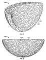
- FIG. 1shows a first view of an illustrative implant component
- FIG. 2shows a second view of an illustrative implant component
- FIG. 3shows an illustrative implant coating volume having a spherical bead surface profile
- FIG. 4shows an illustrative unit cell having a porous structure
- FIG. 5shows a cross-section of an illustrative coating volume with a spherical bead profile and a porous structure
- FIG. 6shows a first illustrative SEM image of a porous surface
- FIG. 7shows a second illustrative SEM image of a porous surface.
- any appropriate reinforcement materialnon-limiting examples of which include bone cement, appropriate polymers, resorbable polyurethane, and/or any materials provided by PolyNovo Biomaterials Limited, or any suitable combinations thereof.
- any appropriate reinforcement materialnon-limiting examples of which include bone cement, appropriate polymers, resorbable polyurethane, and/or any materials provided by PolyNovo Biomaterials Limited, or any suitable combinations thereof.
- Further non-limiting examples of potential materials that may be usedare described in the following references: U.S. Patent Application Publication No. 2006/0051394, entitled “Biodegradable Polyurethane and Polyurethane Ureas,” U.S. Patent Application Publication No. 2005/0197422, entitled “Biocompatible Polymer Compositions for Dual or Multi Staged Curing,” U.S. Patent Application Publication No.
- certain embodimentsprovide components having porous beaded coatings and methods for their manufacture. Because implants and natural bone usually have different degrees of flexibility, uneven stress distributions may occur. Consequently, when an implant is loaded, there is generally some relative movement at the interface between the bone (more compliant) and the implant (more rigid). Many implants thus employ an intermediate material such as bone cement to reduce the amount of relative movement; however, cementless implants may rely on relative roughness to achieve the same goals.
- protrusionscan cause problems when there is even a small amount of relative movement between the bone and implant.
- the sharper protrusionscan dig into the bone and create bone particles or can break off from the implant and create wear particles at the implant-bone interface. In addition to loosening the attachment between the implant and bone, these loose particles can cause harmful complications.
- an implanthaving a surface that is textured with numerous blunt protrusions on a macroscopic level and has a porous structure on a microscopic level.
- the blunt protrusionscreate friction that reduces the amount of relative movement between an implanted component and surrounding bone.
- the porosityallows the surrounding bone to grow into the implant, and the lack of relative movement between implant and bone facilitates this ingrowth.
- a consideration in designing and creating a porous implant having blunt protrusionsis the size and density of the protrusions.
- the protrusionscreate an area on which the bone initially contacts an implant. If the protrusions are too large or spaced too far apart, the majority of the implant's surface area between the protrusions will be too far from the bone for the bone to grow into the implant, and the bone may be unable to create a solid interface with the implant. In contrast, if the protrusions are too small or located too close together, their effect will be minimal and an implant may encounter the same problems as prior implants with smoother surfaces or surfaces composed of many concentrated sharp protrusions.
- An ideal surfacecontains protrusions that are large enough to create the needed friction between the bone and implant and still small enough to still allow for a high degree of bone ingrowth into the porous surface.
- the protrusionsmay be any suitable height, and preferably are between about 50 ⁇ m and about 2000 ⁇ m. For certain applications, it may be preferable to limit the protrusion heights to between 200 ⁇ m and 400 ⁇ m to achieve the desired level of friction and ingrowth with surrounding bone.
- Protrusions on a surface of an implantable componentmay be any suitable shape or profile desired for a general or specific application of the component.
- each surface protrusionmay be a bump shaped as a portion of a sphere above the surface of the implant.
- Protrusionsmay also be shaped like wires or any other suitable features, including features common to cementless implants.
- FIGS. 1 and 2show some embodiments of an improved acetabular implant 1500 which may be a whole augment, a portion of an augment, a flange, a plate, other mounting member, a shell, or a cage.
- the improved acetabular implant 1500mimics the bumpy outer surface geometries and profiles of clinically-successful porous beads, with the roughness and porosity of a desired ingrowth interface.
- the surface of implant 1500is textured by blunt protrusions 1502 , which are shaped substantially as hemispherical bumps on the surface of implant 1500 .
- the protrusions 1502are sized and spaced to create desirable friction that reduces movement of the implant 1500 relative to surrounding bone while allowing the surrounding bone to grow substantially into the porous protrusions 1502 and porous surface area 1504 between the protrusions.
- the spacing and density of protrusions 1502affect the amount of friction and bone ingrowth created. Any suitable density of protrusions 1502 may be used for an implant, and the protrusions preferably occupy between about 10% and about 60% of the surface.
- the protrusionsmay be concentrated to a density of between about 0.25 beads/mm 2 and about 6 beads/mm 2 .
- Improved acetabular implantssuch as the implant 1500 of FIGS. 1 and 2 , may be formed by any suitable approach, and may be formed using one of the following four methods.
- a first methodincludes the steps of: 1) providing a mold having a negative impression of a porous beaded surface, 2) providing an implant substrate, which may be solid or porous, to be coated, 3) interposing small asymmetric particles between the implant substrate and said mold, and 4) applying a pressure and/or an elevated temperature to the mold, implant substrate, and small asymmetric particles to create a “green-state” implant (i.e., ready for full sintering) or a final implant (sintered), the implant having a roughened porous coating with an outer surface geometries and profiles mimicking a clinically-proven porous beaded structure with the roughness and porosity of a desired trabecular structure.
- a second methodincludes the steps of: 1) creating a 3D model simulating an outer surface profile of a porous beaded implant, 2) creating a model of an implant substrate volume, 3) applying the 3D model simulating an outer surface profile of a porous beaded implant to the 3D model of the implant substrate volume to create a bumpy pre-form volume, 4) applying an algorithm to fill the bumpy pre-form volume with a desired interconnected porous or otherwise reticulated structure to create a porous implant model, and 5) creating an implant having a roughened porous texture with an outer surface profile geometry mimicking a clinically-proven porous beaded structure using the implant model in a rapid-manufacturing process.
- a third methodincludes the steps of: 1) providing a mold of an implant having an inner surface mimicking a negative image of an outer surface profile geometry of a porous beaded surface, 2) providing a plurality of small asymmetric particles, 3) placing the plurality of small asymmetric particles into the mold, and 4) applying a pressure and/or an elevated temperature to the mold and/or small asymmetric particles to create a “green-state” implant (i.e., ready for full sintering) or a final implant (sintered), the implant having a roughened porous texture with an outer surface profile geometry mimicking a clinically-proven porous beaded structure.
- a fourth methodincludes the creation of a beaded surface on a foam component during the precursor step of making a metallic foam, the method comprising the steps of: 1) providing a mold of an implant having an inner surface mimicking a negative image of an outer surface profile geometry of a porous beaded surface, 2) loading one or more foaming agents into the mold, 3) creating a porous foam component (e.g., polymeric, polyurethane) in the general shape and/or size of said implant, which has an outer surface geometry mimicking an outer surface profile geometry of a porous beaded surface, 4) removing the porous foam component from the mold, 5) applying a binder or binding agent to the porous foam component, 6) applying a plurality of small symmetric or asymmetric particles (or a combination thereof) to the porous foam component having a binder or binding agent thereon, 7) subjecting the porous foam component having binder or binding agent and particles thereon to an elevated temperature to sinter the particles together and/or burn out the foam component to form a “green-state
- the substrate forming at least an outer portion of the implantmay be a bulk porous, reticulated structure resembling a trabecular structure.
- One or more core portions or outer surface portions of the implantmay be solid (e.g., a portion of the implant may be configured for articulation with another implant component).
- the implantmay also include one or more solid internal portions.
- implant 1500 shown in FIG. 1may include a solid structural portion on the interior of the implant.
- the structural portionmay be a single solid area or multiple solid areas on the interior of implant 1500 that provide a series of structural ribs to add support to the implant.
- the solid internal structuremay have any suitable shape and configuration, such as a structural lattice similar to rebar in concrete.
- Illustrative but non-limiting examples areas where the internal structure may be desiredinclude areas around screw holes, the equator region of an augment, or any other suitable area.
- a polymer foamcould be melted or burned to have the shape of beads—or the foam could be polymerized on a bead-shaped subsurface resulting in the end-product having a bead-shaped surface.
- implant 1500may be coupled with external flanges or other mounting members to provide additional support to the implant.
- implant 1500may be implanted along with a flange that is attached to the implant at a first end of the flange and attached to a patient's bone at a second end, for example, with a bone screw secured into a through-hole in the flange.
- Implant 1500may also include external solid reinforcements, similar to common strut and brace structures, to provide support to porous sections of the implant.
- the bead surface geometries and profilecould be created virtually and subtracted out from a bulk porous entity or virtual beads could be created and combined with a porous entity. It is the general intent, in some, but not necessarily all, embodiments that the end-product be homogenous. Alternate embodiments of implants may include surface profiles that mimic metallic wire bundles or the peaks and valleys of a thermal sprayed coating.
- an implant component having the desired surface profilecan be created using any suitable rapid manufacturing techniques.
- the porous implantcan be created using 3D printing technology that uses powdered metal to “print” the modeled implant.
- a foammay be created having a surface profile that includes protrusions, such as protrusions 1502 in FIGS. 1 and 2 , and the profiled foam may then be filled in with powdered metal to create a porous microstructure with the profiled surface.
- a foam that does not contain the protrusionsmay also be used to create the porous microstructure with powdered metal, and the desired surface profile with protrusions can then be stamped into the surface of the porous metal implant.
- implants manufactured this waycontain integral porosity with the initially bone-engaging surface profile of clinically-proven porous beads.
- the same features providing the traction needed between bone and implantare the same features providing a surface for bone to grow into and around for a rigid and enduring fixation surface.
- Tables A and Bshow some examples of potentially suitable bead density (spacing), and diameter.
- Percent Solidfor typical beaded product for bone ingrowth.
- “percent solid”is a 2D measurement of bead density produced by typical metallographic techniques based on the test method disclosed in ASTM F1854, entitled “Standard Test Method for Stereological Evaluation of Porous Coatings on Medical Implants,” which is incorporated by reference herein in its entirety.
- FIG. 3shows a coating volume 1510 having spherical bead volumes 1512 placed therein, such that the spherical bead volumes 1512 protrude from the coating volume 1510 to form a second coating volume mimicking a spherical bead profile.
- solid spherical beadsmay be combined into a porous coating.
- a first model of a macroscopic structure of the volume, including the plurality of bead volumes 1512can be created in modeling software, and may look substantially the same as the volume shown in FIG. 3 .
- FIG. 4shows a unit cell 1520 of an exemplary porous reticulated structure, which may configured to fill the coating volume mimicking a spherical bead profile.
- the unit cell 1520is made up of a complex structure of struts 1512 .
- the arrangement of struts 1512creates voids 1514 within unit cell 1520 , thus making the desired porous microstructure.
- the size and arrangement of struts 1512can be varied to control the number and size of voids 1514 . By controlling the size and arrangement of the struts 1512 , a desired amount and profile of the porous structure is achieved.
- FIG. 5shows a cross section of a coating volume 1530 , which may correspond to coating volume 1510 of FIG. 3 , mimicking a spherical bead profile after the volume has been replaced with a reticulated structure (e.g., via a repeating unit cell such as unit cell 1520 in FIG. 4 in CAS software, or using any of the 4 methods described above).
- the finished coating volume 1530exhibits both the profiled macrostructure and porous microstructure.
- the dotted lines in FIG. 5outline the surface profile of coating volume 1530 and show the protrusions that create a bumpy surface that produces friction with bone when implanted.
- the microstructure of coating volume 1530made up of a combination of solid structure 1532 and voids 1534 , creates a porous implant into which surrounding bone can grow to fill in voids 1534 and create a solid mating of implant and bone.
- FIG. 6shows an SEM image 1540 taken at 25 ⁇ magnification of the surface of a part made by the disclosed method. Surface topography is not apparent with this view.
- FIG. 7is an SEM image taken 1550 at 50 ⁇ magnification of the structure made with the disclosed method.
- the structures shown in FIGS. 6 and 7exhibit the porous microstructure discussed above with respect to coating volumes 1510 and 1530 , and can be created by merging a solid macrostructure with a porous microstructure model, such as the unit cell 1520 in FIG. 4 .
- MVILrefers to Mean Void Intercept Length, which is another way of characterizing the average pore size, particularly in structures where the pore shapes and sizes are not uniform.
- Measurement grid linesare oriented parallel to the substrate interface. The number of times the lines intercept voids is used with the volume percent void to calculate the mean void intercept length.”
- Electron Direct metal beam laser sintering Landon melting (SLS) Structure (EBM) Eurocoating EOS (FIG. 4)Avg. Strut Thickness ( ⁇ m) — 275-450 275-400 (360) (340) Avg. Pore Size: MVIL 300-920* 450-690 — (565) (560) Average Pore 900-1300* 1310 ⁇ 280 1970 ⁇ 40 Pore Window — 370 ⁇ 100 830 ⁇ 150 Size: ( ⁇ m) Not Specified 670-1340 600 ⁇ 100 — *(fine, medium, and coarse structures)
- Pore sizesmay generally range between about 50-1000 microns.
- the smallest pore size providedwas about 300 microns, and the smallest window was about 595 microns across at its largest diameter. It will be understood that this example is intended to be non-limiting and provided for illustrative purposes only.
- the systems, methods, and devices described herein to create implants having both a profiled macrostructure and a porous microstructurecan allow a medical professional to utilize customizable, patient-specific implants.
- a customized implantcan be efficiently created using the rapid manufacturing techniques discussed herein by merging two or more models of an implant and then printing the modeled component. This could allow a medical professional, such as an orthopedic surgeon, to order an implant specific to a single patient, including modeling the size and shape of the implant to fit defects or other unique features of the patient's anatomy.
- This processcan also be automated by taking bone scans of the patient's anatomy or using other available medical imaging and modeling techniques to automatically create a 3D model to use for rapid manufacturing.
- the ability to customize an individual implantalso allows a medical professional to adjust the detailed macrostructure and microstructure of the implant to fit the needs of a particular application.
- an orthopedic surgeoncan adjust the macrostructure of the implant by selecting the shape, height, density, or other characteristics of protrusions on the surface of the implant.
- the surgeoncan also customize the number and size of voids within the implant to achieve a desired porosity for the implant.
- the surgeonmay also select the configuration of the macrostructure of the implant.
- the surgeoncan customize the size and location of the internal solid portions to provide the structure in certain non-uniform areas of the implant where increased strength is needed.
- Illustrative but non-limiting examples areas where increased strength may be desiredinclude areas around screw holes, the equator region of an augment, connection sites of augments, augment areas that are thinner than others, or any other suitable area.
- the surface profile of the implantcan also be non-uniform if different areas of the implant require different levels of friction or surface area for a bone interface. A surgeon may want a higher concentration of surface protrusions in certain areas of the implant, such as areas that experience higher levels of stress, and a lower concentration of protrusions, or no protrusions at all, in other areas.
- Porous implants described hereinallow for an implant to provide good contact surface area and friction regardless of the quality of bone into which an implant is implanted. For example, patients who have soft spongy bone may need features that are longer, and a lower number of those features. Patients with hard dense bone may require features that are shorter, but a higher number of those features to create the same fixation in the bone. The specific requirements of a patient's anatomy and bone quality can be accommodated by the individualized design options provided by the porous implants described herein.
Landscapes
- Health & Medical Sciences (AREA)
- Orthopedic Medicine & Surgery (AREA)
- Engineering & Computer Science (AREA)
- Life Sciences & Earth Sciences (AREA)
- Veterinary Medicine (AREA)
- Animal Behavior & Ethology (AREA)
- Biomedical Technology (AREA)
- Heart & Thoracic Surgery (AREA)
- Public Health (AREA)
- General Health & Medical Sciences (AREA)
- Transplantation (AREA)
- Oral & Maxillofacial Surgery (AREA)
- Cardiology (AREA)
- Vascular Medicine (AREA)
- Surgery (AREA)
- Software Systems (AREA)
- Theoretical Computer Science (AREA)
- Neurology (AREA)
- Nuclear Medicine, Radiotherapy & Molecular Imaging (AREA)
- Medical Informatics (AREA)
- Molecular Biology (AREA)
- Manufacturing & Machinery (AREA)
- General Engineering & Computer Science (AREA)
- General Physics & Mathematics (AREA)
- Physics & Mathematics (AREA)
- Physical Education & Sports Medicine (AREA)
- Prostheses (AREA)
- Surgical Instruments (AREA)
- Storage Device Security (AREA)
Abstract
Description
This application claims the benefit of U.S. Provisional Patent Application No. 61/352,705, filed Jun. 8, 2010, U.S. Provisional Application No. 61/352,722, filed Jun. 8, 2010, U.S. Provisional Application No. 61/422,903, filed Dec. 14, 2010, and U.S. Provisional Application No. 61/466,817, filed Mar. 23, 2011, which are hereby incorporated by reference herein in their entireties.
Joints often undergo degenerative changes due to a variety of reasons. When joint degeneration becomes advanced or irreversible, it may become necessary to replace the natural joint with a prosthetic joint. Artificial implants, including hip joints, shoulder joints, and knee joints are widely used in orthopedic surgery. Specifically, hip joint prostheses are common. The human hip joint acts mechanically as a ball and socket joint, wherein the ball-shaped head of the femur is positioned within the socket-shaped acetabulum of the pelvis. Various degenerative diseases and injuries may require replacement of all or a portion of a hip using synthetic materials, typically metals, ceramics, or plastics.
More particularly, natural hips often undergo degenerative changes, requiring replacement of the hip joint with a prosthetic joint. Often, the hip is replaced with two bearing surfaces between the femoral head and the acetabulum. The first bearing surface is typically a prosthesis shell or acetabular cup, which may be formed of metal, ceramic material, or as otherwise desired. A liner (conventionally formed of polyethylene material such as ultra high molecular weight polyethylene, a ceramic material, or in some cases, even a metal liner) is then fit tightly within the shell to provide an inner bearing surface that receives and cooperates with an artificial femoral head in an articulating relationship to track and accommodate the relative movement between the femur and the acetabulum.
The cup (or a cup and liner assembly) is typically fixed either by placing screws through apertures in the cup or by securing the cup with cement. In some cases, only a liner is cemented in a patient due to poor bone stock. In other cases, a cup having a porous surface may be press fit into the reamed acetabular surface.
It may become necessary to conduct a second or subsequent surgery in order to replace a prosthetic joint with a (often larger) replacement joint. Such surgeries often become necessary due to further degeneration of bone or advancement of a degenerative disease, requiring removal of further bone and replacement of the removed, diseased bone with a larger or enhanced prosthetic joint, often referred to as a revision prosthesis. For example, bone is often lost around the rim of the acetabulum, and this may provide less rim coverage to securely place a press-fit cup. Such surgeries may thus be referred to as revision surgeries.
In acetabular revision surgery, an acetabular prosthesis generally includes additional mounting elements, such as augments, flanges, hooks, plates, or any other attachment or mounting points or members that provide additional support and/or stability for the replacement prosthesis once positioned. These additional mounting or attachment members are often required due to bone degeneration, bone loss, or bone defects in the affected area (in this instance, the hip joint).
Various types of these mounting members (which term is intended to include but not be limited to flanges, blades, plates and/or hooks) may be provided in conjunction with a prosthesis system in order to help the surgeon achieve optimal fixation, non-limiting examples of which include iliac flanges (providing securement and fixation in and against the ilium region of the pelvis), ischial blades (providing securement and fixation in and against the ischium), and obturator hooks (providing securement and inferior fixation by engaging the obturator foramen). Although there have been attempts to provide such mounting attachments with modularity, the solutions to date have generally fallen short of providing true modularity. Instead, they typically provide a few discrete positions at which the mounting members may be positioned, without providing the surgeon a fuller range of decision options.
Additionally, in some primary surgeries and more often in revision surgeries, the acetabulum may have a bone defect or void that the surgeon must fill with bone grafts before inserting a new shell. This can be time consuming and expensive, and may subject the patient to additional health risks. Some techniques use an augment in connection with the acetabular shell, which can be coupled to or otherwise attached to the outer surface of the shell.
With current augments, the surgeon can attach the augment to the bone and then implant the cup. However, many acetabular shells rely on bone screws to achieve proper fixation and the augment often gets in the way of a screw. In short, surgeons need the freedom to place screws in the best location, but this compromises their ability to use augments. With current systems, it also takes an increased amount of time surgical time to trial the component orientation and then try to find good bone fixation for the cup. The surgeon will often have to free-hand the amount of bone removed while estimating the size of augment needed. In the cases where bone is often deficient, surgeons are hesitant to take away any more bone than necessary.
Various additional features and improved features intended for use and application with various types of joint implants are also described herein, such as improved bone screws, improved coatings, and various augment removal and insertion options.
Disclosed herein are systems, devices, and methods for providing modular orthopedic implants. The implants may include a base member, such as an acetabular shell or an augment, that is configured to couple with an augment, flange cup, mounting member, any other suitable orthopedic attachment, or any combinations thereof. Mounting members include, for example, flanges, blades, hooks, and plates. In some embodiments, the orthopedic attachments may be adjustably positionable about the base member or other attachments thereby providing modularity for assembling and implanting the device. Various securing and/or locking mechanisms may be used between the components of the implant. In certain embodiments, the orthopedic attachments are removably coupled to the base member or other components. In certain embodiments, the orthopedic attachments are integrally provided on the base member or other components, yet may still be adjustably positionable thereabout. In some embodiments, expandable augments, base members, or other bone filling devices are provided. In some embodiments, surface features are provided that create friction and allow for surrounding bone ingrowth at the interface of the implants and a patient's bone.
Systems, devices, and methods described herein provide implants that create friction and allow for surrounding bone ingrowth at the interface of the implants and a patient's bone. In certain embodiments, an implantable orthopedic device includes an implant that has a surface that contacts a patient's joint and has a plurality of protrusions connected to the surface that rise above the surface. The implant may also include pores dispersed throughout the surface at the bone interface. The protrusions located at the surface of the implant may be blunt, or may be any other suitable shape and configuration. The protrusions may extend from the surface to any suitable height, such as heights between about 50 μm and about 2000 μm, heights between about 100 μm and 1100 μm, or heights between about 200 μm and 400 μm. The protrusions may be spaced on the surface of the implant in any suitable concentration or density. The desired protrusion density may also be patient-specific, and may be determined based on the density of a native bone into which a component is implanted. An implant may have a large number of protrusion features on its surface, and one or more of these individual features may fall outside of a desired size or spacing without affecting the overall efficacy of the surface.
In certain embodiments, an implant includes internal or external strengthening features. A porous implant may include internal or external strengthening ribs to provide support to surrounding porous structures. A porous implant may also be coupled with a flange that has a first end for attaching the flange to the implant and a second end for attaching the flange to surrounding bone structure. The porous implant may also include a reticulated surface coating.
In certain embodiments, an implantable orthopedic device is created by providing a mold having a negative impression of a porous beaded surface and providing an implant substrate to be coated. Particles are interposed between the implant substrate and the mold, and a pressure or elevated temperature may be applied to the mold, implant substrate, and particles. The implant substrate provided may be solid or may be porous, and the particles interposed between the implant substrate and the mold may be symmetric or asymmetric.
In certain embodiments, an implantable orthopedic device is created by creating a three-dimensional model simulating an outer surface profile of a porous beaded implant and creating a three-dimensional model of an implant substrate volume. The model simulating an outer surface profile of a porous beaded implant is applied to the model of an implant substrate volume to create a pre-form volume, and an algorithm is applied to fill the pre-form volume with a desired reticulated structure to create a porous implant model. An implant is formed using the porous implant model.
In certain embodiments, an implantable orthopedic device is created by providing a mold of an implant having an inner surface mimicking a negative image of an outer surface profile geometry of a porous beaded surface and providing a plurality of particles that are placed into the mold. Pressure or elevated temperature is applied to the mold and particles. The particles placed into the mold may be symmetric or asymmetric.
In certain embodiments, an implantable orthopedic device is created by providing a mold of an implant having an inner surface mimicking a negative image of an outer surface profile geometry of a porous beaded surface and loading one or more foaming agents into the mold. A porous foam component is created in the general shape or size of the implant that has an outer surface geometry mimicking an outer surface profile geometry of a porous beaded surface. The porous foam component is removed from the mold, and a binding agent is applied to the porous foam component. A plurality of symmetric or asymmetric particles are applied to the porous foam component having the binding agent and the porous foam component, binding agent, and particles are subjected to an elevated temperature to sinter the particles together and burn out the foam component to form an implant having a roughened porous texture with an outer surface profile geometry mimicking a clinically-proven porous beaded structure. The porous foam component may be polymeric, and may be a polyurethane component.
The foregoing and other objects and advantages will be apparent upon consideration of the following detailed description, taken in conjunction with the accompanying drawings, in which like reference characters refer to like parts throughout, and in which:
To provide an overall understanding of the systems, devices, and methods described herein, certain illustrative embodiments will be described. Although the embodiments and features described herein are specifically described for use in connection with acetabular systems, it will be understood that all the components, connection mechanisms, adjustable systems, fixation methods, manufacturing methods, coatings, and other features outlined below may be combined with one another in any suitable manner and may be adapted and applied to medical devices and implants to be used in other surgical procedures, including, but not limited to: spine arthroplasty, cranio-maxillofacial surgical procedures, knee arthroplasty, shoulder arthroplasty, as well as foot, ankle, hand, and other extremity procedures.
Various implants and other devices described herein in their various embodiments may be used in conjunction with any appropriate reinforcement material, non-limiting examples of which include bone cement, appropriate polymers, resorbable polyurethane, and/or any materials provided by PolyNovo Biomaterials Limited, or any suitable combinations thereof. Further non-limiting examples of potential materials that may be used are described in the following references: U.S. Patent Application Publication No. 2006/0051394, entitled “Biodegradable Polyurethane and Polyurethane Ureas,” U.S. Patent Application Publication No. 2005/0197422, entitled “Biocompatible Polymer Compositions for Dual or Multi Staged Curing,” U.S. Patent Application Publication No. 2005/0238683, entitled “Biodegradable Polyurethane/Urea Compositions,” U.S. Patent Application Publication No. 2007/0225387, entitled “Polymer Compositions for Dual or Multi Staged Curing,” U.S. Patent Application Publication No. 2009/0324675, entitled “Biocompatible Polymer Compositions,” U.S. Patent Application Publication No. 2009/0175921, entitled “Chain Extenders,” and U.S. Patent Application Publication No. 2009/0099600, entitled “High Modulus Polyurethane and Polyurethane/Urea Compositions.” Each of the prior references is incorporated by reference herein in its entirety.
Referring now toFIGS. 1-7 , certain embodiments provide components having porous beaded coatings and methods for their manufacture. Because implants and natural bone usually have different degrees of flexibility, uneven stress distributions may occur. Consequently, when an implant is loaded, there is generally some relative movement at the interface between the bone (more compliant) and the implant (more rigid). Many implants thus employ an intermediate material such as bone cement to reduce the amount of relative movement; however, cementless implants may rely on relative roughness to achieve the same goals.
Historically, small spherical beads, bundles of thin wires, and thermal-sprayed metal have been used to produce the friction necessary to reduce the amount of relative movement. Optionally, screws and/or press-fit features may improve the fixation of implant to bone. Such technologies are generally accepted by the orthopedic surgeon community. However, the geometric nature of these coatings limits the location and size of their porosity. Newer technologies, such as those that employ asymmetric beads or metallic foams have improved the location and size of porosity, but they are difficult to manufacture with favorable surface textures. Remedies have included placing hatch lines into the surface of an already porous coating (e.g., via machining). Other porous surfaces have been manufactured having sharp protrusions at a microscopic level. These protrusions can cause problems when there is even a small amount of relative movement between the bone and implant. The sharper protrusions can dig into the bone and create bone particles or can break off from the implant and create wear particles at the implant-bone interface. In addition to loosening the attachment between the implant and bone, these loose particles can cause harmful complications.
The shortcomings of previous porous surfaces are addressed by providing an implant having a surface that is textured with numerous blunt protrusions on a macroscopic level and has a porous structure on a microscopic level. The blunt protrusions create friction that reduces the amount of relative movement between an implanted component and surrounding bone. The porosity allows the surrounding bone to grow into the implant, and the lack of relative movement between implant and bone facilitates this ingrowth.
A consideration in designing and creating a porous implant having blunt protrusions is the size and density of the protrusions. The protrusions create an area on which the bone initially contacts an implant. If the protrusions are too large or spaced too far apart, the majority of the implant's surface area between the protrusions will be too far from the bone for the bone to grow into the implant, and the bone may be unable to create a solid interface with the implant. In contrast, if the protrusions are too small or located too close together, their effect will be minimal and an implant may encounter the same problems as prior implants with smoother surfaces or surfaces composed of many concentrated sharp protrusions. An ideal surface contains protrusions that are large enough to create the needed friction between the bone and implant and still small enough to still allow for a high degree of bone ingrowth into the porous surface. The protrusions may be any suitable height, and preferably are between about 50 μm and about 2000 μm. For certain applications, it may be preferable to limit the protrusion heights to between 200 μm and 400 μm to achieve the desired level of friction and ingrowth with surrounding bone.
Protrusions on a surface of an implantable component may be any suitable shape or profile desired for a general or specific application of the component. In certain embodiments, each surface protrusion may be a bump shaped as a portion of a sphere above the surface of the implant. Protrusions may also be shaped like wires or any other suitable features, including features common to cementless implants.
Improved acetabular implants, such as theimplant 1500 ofFIGS. 1 and 2 , may be formed by any suitable approach, and may be formed using one of the following four methods.
A first method includes the steps of: 1) providing a mold having a negative impression of a porous beaded surface, 2) providing an implant substrate, which may be solid or porous, to be coated, 3) interposing small asymmetric particles between the implant substrate and said mold, and 4) applying a pressure and/or an elevated temperature to the mold, implant substrate, and small asymmetric particles to create a “green-state” implant (i.e., ready for full sintering) or a final implant (sintered), the implant having a roughened porous coating with an outer surface geometries and profiles mimicking a clinically-proven porous beaded structure with the roughness and porosity of a desired trabecular structure.
A second method includes the steps of: 1) creating a 3D model simulating an outer surface profile of a porous beaded implant, 2) creating a model of an implant substrate volume, 3) applying the 3D model simulating an outer surface profile of a porous beaded implant to the 3D model of the implant substrate volume to create a bumpy pre-form volume, 4) applying an algorithm to fill the bumpy pre-form volume with a desired interconnected porous or otherwise reticulated structure to create a porous implant model, and 5) creating an implant having a roughened porous texture with an outer surface profile geometry mimicking a clinically-proven porous beaded structure using the implant model in a rapid-manufacturing process.
A third method includes the steps of: 1) providing a mold of an implant having an inner surface mimicking a negative image of an outer surface profile geometry of a porous beaded surface, 2) providing a plurality of small asymmetric particles, 3) placing the plurality of small asymmetric particles into the mold, and 4) applying a pressure and/or an elevated temperature to the mold and/or small asymmetric particles to create a “green-state” implant (i.e., ready for full sintering) or a final implant (sintered), the implant having a roughened porous texture with an outer surface profile geometry mimicking a clinically-proven porous beaded structure.
A fourth method includes the creation of a beaded surface on a foam component during the precursor step of making a metallic foam, the method comprising the steps of: 1) providing a mold of an implant having an inner surface mimicking a negative image of an outer surface profile geometry of a porous beaded surface, 2) loading one or more foaming agents into the mold, 3) creating a porous foam component (e.g., polymeric, polyurethane) in the general shape and/or size of said implant, which has an outer surface geometry mimicking an outer surface profile geometry of a porous beaded surface, 4) removing the porous foam component from the mold, 5) applying a binder or binding agent to the porous foam component, 6) applying a plurality of small symmetric or asymmetric particles (or a combination thereof) to the porous foam component having a binder or binding agent thereon, 7) subjecting the porous foam component having binder or binding agent and particles thereon to an elevated temperature to sinter the particles together and/or burn out the foam component to form a “green-state” implant (i.e., ready for full sintering) or a final implant (sintered), the implant having a roughened porous texture with an outer surface profile geometry mimicking a clinically-proven porous beaded structure. Implant has a bumpy outer surface profile and geometries mimicking a clinically-proven porous-beaded structure.
The substrate forming at least an outer portion of the implant may be a bulk porous, reticulated structure resembling a trabecular structure. One or more core portions or outer surface portions of the implant may be solid (e.g., a portion of the implant may be configured for articulation with another implant component). The implant may also include one or more solid internal portions. For example,implant 1500 shown inFIG. 1 may include a solid structural portion on the interior of the implant. The structural portion may be a single solid area or multiple solid areas on the interior ofimplant 1500 that provide a series of structural ribs to add support to the implant. The solid internal structure may have any suitable shape and configuration, such as a structural lattice similar to rebar in concrete. Illustrative but non-limiting examples areas where the internal structure may be desired include areas around screw holes, the equator region of an augment, or any other suitable area. In some embodiments, a polymer foam could be melted or burned to have the shape of beads—or the foam could be polymerized on a bead-shaped subsurface resulting in the end-product having a bead-shaped surface. In addition to solid internal components,implant 1500 may be coupled with external flanges or other mounting members to provide additional support to the implant. For example,implant 1500 may be implanted along with a flange that is attached to the implant at a first end of the flange and attached to a patient's bone at a second end, for example, with a bone screw secured into a through-hole in the flange.Implant 1500 may also include external solid reinforcements, similar to common strut and brace structures, to provide support to porous sections of the implant.
For rapid-manufacturing technologies, the bead surface geometries and profile could be created virtually and subtracted out from a bulk porous entity or virtual beads could be created and combined with a porous entity. It is the general intent, in some, but not necessarily all, embodiments that the end-product be homogenous. Alternate embodiments of implants may include surface profiles that mimic metallic wire bundles or the peaks and valleys of a thermal sprayed coating. Once a virtual model of the desired geometry is created using modeling software, an implant component having the desired surface profile can be created using any suitable rapid manufacturing techniques. For example, the porous implant can be created using 3D printing technology that uses powdered metal to “print” the modeled implant. In such an approach, a foam may be created having a surface profile that includes protrusions, such asprotrusions 1502 inFIGS. 1 and 2 , and the profiled foam may then be filled in with powdered metal to create a porous microstructure with the profiled surface. A foam that does not contain the protrusions may also be used to create the porous microstructure with powdered metal, and the desired surface profile with protrusions can then be stamped into the surface of the porous metal implant.
Advantages of implants manufactured this way are that they contain integral porosity with the initially bone-engaging surface profile of clinically-proven porous beads. In other words, the same features providing the traction needed between bone and implant are the same features providing a surface for bone to grow into and around for a rigid and enduring fixation surface. As non-limiting examples, Tables A and B show some examples of potentially suitable bead density (spacing), and diameter.
| TABLE A |
| Chart of number of beads in selected area and average and standard |
| deviation of bead diameter of 50 beads on a shell used with the |
| Birmingham Hip ® Resurfacing system available from Smith & |
| Nephew, Inc. in at least 3 fields of view (SEM, Jeol, Japan) |
| Beads in 6.4 × | Bead Diamter | |
| 4.8 mm area | (mm) | |
| 11 | Average D | 1.24 |
| 20 | Std D | 0.12 |
| 20 | ||
| TABLE B |
| Percent solid for typical beaded product for bone ingrowth. |
| Percent | |||
| Product | Company | Implant Type | Solid |
| CoCr ROUGHCOAT | Smith and | Profix ® Femoral | 46.3% |
| (2-layer) | Nephew | ||
| CoCr Porocoat | DePuy | LCS ® Knee Femoral | 46.5% |
| (3-layer) | |||
| CoCr Porocoat | DePuy | AML ® Stem | 50.2% |
| (3-layer) | |||
| Ti ROUGHCOAT | Smith and | Synergy ™ Stem | 51.9% |
| (2-layer) | Nephew | ||
| Wherein, “percent solid” is a 2D measurement of bead density produced by typical metallographic techniques based on the test method disclosed in ASTM F1854, entitled “Standard Test Method for Stereological Evaluation of Porous Coatings on Medical Implants,” which is incorporated by reference herein in its entirety. | |||
A second software model can be created to produce the porous microscopic structure desired for a macroscopic volume, such as the volume shown inFIG. 3 .FIG. 4 shows aunit cell 1520 of an exemplary porous reticulated structure, which may configured to fill the coating volume mimicking a spherical bead profile. Theunit cell 1520 is made up of a complex structure ofstruts 1512. The arrangement ofstruts 1512 createsvoids 1514 withinunit cell 1520, thus making the desired porous microstructure. The size and arrangement ofstruts 1512 can be varied to control the number and size ofvoids 1514. By controlling the size and arrangement of thestruts 1512, a desired amount and profile of the porous structure is achieved.
As a further non-limiting example, the following chart shows some additional exemplary parameters that have proven to be useful for various embodiments. In the chart below, MVIL refers to Mean Void Intercept Length, which is another way of characterizing the average pore size, particularly in structures where the pore shapes and sizes are not uniform. On generally known definition of MVIL is “measurement grid lines are oriented parallel to the substrate interface. The number of times the lines intercept voids is used with the volume percent void to calculate the mean void intercept length.”
| Electron | Direct metal | |||
| beam | laser sintering | Landon | ||
| melting | (SLS) | Structure | ||
| (EBM) | Eurocoating EOS | (FIG. 4) | ||
| Avg. Strut Thickness (μm) | — | 275-450 | 275-400 |
| (360) | (340) | ||
| Avg. Pore Size: MVIL | 300-920* | 450-690 | — |
| (565) | (560) |
| Average | Pore | 900-1300* | 1310 ± 280 | 1970 ± 40 |
| Pore | Window | — | 370 ± 100 | 830 ± 150 |
| Size: (μm) | Not Specified | 670-1340 | 600 ± 100 | — |
| *(fine, medium, and coarse structures) | ||||
It is generally desirable to provide between about 60-85% porosity. Pore sizes may generally range between about 50-1000 microns. In the above example, the smallest pore size provided was about 300 microns, and the smallest window was about 595 microns across at its largest diameter. It will be understood that this example is intended to be non-limiting and provided for illustrative purposes only.
The systems, methods, and devices described herein to create implants having both a profiled macrostructure and a porous microstructure can allow a medical professional to utilize customizable, patient-specific implants. A customized implant can be efficiently created using the rapid manufacturing techniques discussed herein by merging two or more models of an implant and then printing the modeled component. This could allow a medical professional, such as an orthopedic surgeon, to order an implant specific to a single patient, including modeling the size and shape of the implant to fit defects or other unique features of the patient's anatomy. This process can also be automated by taking bone scans of the patient's anatomy or using other available medical imaging and modeling techniques to automatically create a 3D model to use for rapid manufacturing.
The ability to customize an individual implant also allows a medical professional to adjust the detailed macrostructure and microstructure of the implant to fit the needs of a particular application. For example, an orthopedic surgeon can adjust the macrostructure of the implant by selecting the shape, height, density, or other characteristics of protrusions on the surface of the implant. The surgeon can also customize the number and size of voids within the implant to achieve a desired porosity for the implant. In some embodiments, the surgeon may also select the configuration of the macrostructure of the implant. For implants that include internal solid portions for strength and structure, the surgeon can customize the size and location of the internal solid portions to provide the structure in certain non-uniform areas of the implant where increased strength is needed. Illustrative but non-limiting examples areas where increased strength may be desired include areas around screw holes, the equator region of an augment, connection sites of augments, augment areas that are thinner than others, or any other suitable area. The surface profile of the implant can also be non-uniform if different areas of the implant require different levels of friction or surface area for a bone interface. A surgeon may want a higher concentration of surface protrusions in certain areas of the implant, such as areas that experience higher levels of stress, and a lower concentration of protrusions, or no protrusions at all, in other areas.
Porous implants described herein allow for an implant to provide good contact surface area and friction regardless of the quality of bone into which an implant is implanted. For example, patients who have soft spongy bone may need features that are longer, and a lower number of those features. Patients with hard dense bone may require features that are shorter, but a higher number of those features to create the same fixation in the bone. The specific requirements of a patient's anatomy and bone quality can be accommodated by the individualized design options provided by the porous implants described herein.
The foregoing is merely illustrative of the principles of the disclosure, and the systems, devices, and methods can be practiced by other than the described embodiments, which are presented for purposes of illustration and not of limitation. It is to be understood that the systems, devices, and methods disclosed herein, while shown for use in acetabular systems, may be applied to medical devices to be used in other surgical procedures including, but not limited to, spine arthroplasty, cranio-maxillofacial surgical procedures, knee arthroplasty, shoulder arthroplasty, as well as foot, ankle, hand, and extremities procedures.
Variations and modifications will occur to those of skill in the art after reviewing this disclosure. The disclosed features may be implemented, in any combination and subcombinations (including multiple dependent combinations and subcombinations), with one or more other features described herein. The various features described or illustrated above, including any components thereof, may be combined or integrated in other systems. Moreover, certain features may be omitted or not implemented.
Examples of changes, substitutions, and alterations are ascertainable by one skilled in the art and could be made without departing from the scope of the information disclosed herein. All references cited herein are incorporated by reference in their entirety and made part of this application.
Claims (20)
1. A method for preparing an implantable orthopedic device, the method comprising:
providing a mold having a negative impression of a porous beaded surface;
providing an implant substrate to be coated;
interposing particles between the implant substrate and the mold; and
applying a pressure or elevated temperature to the mold, implant substrate, and particles to create an implant having a surface that matches the porous beaded surface of the mold and is formed from the interposed particles.
2. The method ofclaim 1 , wherein the implant substrate is solid or porous.
3. The method ofclaim 1 , wherein the particles are asymmetric.
4. A method for preparing an implantable orthopedic device, the method comprising:
creating, with a processor, a three-dimensional model simulating an outer surface profile of a porous beaded implant;
creating, with the processor, a three-dimensional model of an implant substrate volume;
applying, with the processor, the three-dimensional model simulating an outer surface profile of a porous beaded implant to the three-dimensional model of an implant substrate volume to create a pre-form volume;
applying, with the processor, an algorithm to fill the pre-form volume with a desired reticulated structure to create a porous implant model; and
forming an implant using the porous implant model.
5. A method for preparing an implantable orthopedic device, the method comprising:
providing a mold of an implant having an inner surface mimicking a negative image of an outer surface profile geometry of a porous beaded surface;
providing a plurality of particles;
placing the plurality of particles into the mold; and
applying a pressure or elevated temperature to the mold to form a surface that matches the porous beaded surface of the mold and is formed from the plurality of particles.
6. The method ofclaim 5 , wherein the particle are asymmetric.
7. A method for preparing an implantable orthopedic device, the method comprising:
providing a mold of an implant having an inner surface mimicking a negative image of an outer surface profile geometry of a porous beaded surface;
loading one or more foaming agents into the mold;
creating a porous foam component in the general shape or size of the implant, the implant having an outer surface geometry mimicking an outer surface profile geometry of a porous beaded surface;
removing the porous foam component from the mold;
applying a binding agent to the porous foam component;
applying a plurality of symmetric or asymmetric particles to the porous foam component having the binding agent thereon;
subjecting the porous foam component having the binding agent and particles thereon to an elevated temperature to sinter the particles together and burn out the foam component to form an implant, the implant having a roughened porous texture with an outer surface profile geometry mimicking a clinically-proven porous beaded structure.
8. The method ofclaim 7 , wherein the porous foam component is polymeric.
9. The method ofclaim 8 , wherein the porous foam component is polyurethane.
10. The method ofclaim 4 , wherein the three-dimensional model simulating an outer surface profile includes blunt protrusions on the modeled surface.
11. The method ofclaim 10 , wherein the modeled protrusions rise to a height between about 50 μm and about 2000 μm.
12. The method ofclaim 11 , wherein the modeled protrusions rise to a height between about 100 μm and about 1100 μm.
13. The method ofclaim 12 ,wherein the modeled protrusions rise to a height between about 200 μm and about 400 μm.
14. The method ofclaim 10 , wherein the modeled protrusions are concentrated at between about 0.25 particles per square millimeter and about 6 particles per square millimeter.
15. The method ofclaim 10 , wherein the porous implant model has a porosity between about 60% and about 85%.
16. The method ofclaim 10 , wherein the modeled protrusions occupy between about 10% and about 60% of the modeled surface profile.
17. The method ofclaim 10 , wherein modeling the desired reticular structure comprises modeling, with the processor, a unit cell of the structure.
18. The method ofclaim 17 , wherein the unit cell includes interconnected modeled struts, with voids defined by the struts.
19. The method ofclaim 18 , wherein the modeled struts have an average thickness between about 275 μm and about 400 μm.
20. The method ofclaim 17 , wherein applying the algorithm comprises applying, with the processor, the unit cell to the pre-form volume.
Priority Applications (3)
| Application Number | Priority Date | Filing Date | Title |
|---|---|---|---|
| US13/156,245US8700198B2 (en) | 2010-06-08 | 2011-06-08 | Implant components and methods |
| US14/191,600US9707083B2 (en) | 2010-06-08 | 2014-02-27 | Implant components and methods |
| US15/596,482US10568741B2 (en) | 2010-06-08 | 2017-05-16 | Implant components and methods |
Applications Claiming Priority (5)
| Application Number | Priority Date | Filing Date | Title |
|---|---|---|---|
| US35270510P | 2010-06-08 | 2010-06-08 | |
| US35272210P | 2010-06-08 | 2010-06-08 | |
| US42290310P | 2010-12-14 | 2010-12-14 | |
| US201161466817P | 2011-03-23 | 2011-03-23 | |
| US13/156,245US8700198B2 (en) | 2010-06-08 | 2011-06-08 | Implant components and methods |
Related Child Applications (1)
| Application Number | Title | Priority Date | Filing Date |
|---|---|---|---|
| US14/191,600DivisionUS9707083B2 (en) | 2010-06-08 | 2014-02-27 | Implant components and methods |
Publications (2)
| Publication Number | Publication Date |
|---|---|
| US20120022662A1 US20120022662A1 (en) | 2012-01-26 |
| US8700198B2true US8700198B2 (en) | 2014-04-15 |
Family
ID=45098648
Family Applications (17)
| Application Number | Title | Priority Date | Filing Date |
|---|---|---|---|
| US13/156,238AbandonedUS20120089235A1 (en) | 2010-06-08 | 2011-06-08 | Implant components and methods |
| US13/156,242AbandonedUS20120016487A1 (en) | 2010-06-08 | 2011-06-08 | Implant components and methods |
| US13/156,245ActiveUS8700198B2 (en) | 2010-06-08 | 2011-06-08 | Implant components and methods |
| US13/156,240AbandonedUS20120083895A1 (en) | 2010-06-08 | 2011-06-08 | Implant components and methods |
| US13/156,248ActiveUS8979926B2 (en) | 2010-06-08 | 2011-06-08 | Implant components |
| US13/156,246AbandonedUS20120016485A1 (en) | 2010-06-08 | 2011-06-08 | Implant components and methods |
| US13/156,241AbandonedUS20120016486A1 (en) | 2010-06-08 | 2011-06-08 | Implant components and methods |
| US14/189,210Active2031-11-11US9901451B2 (en) | 2010-06-08 | 2014-02-25 | Implant components and methods |
| US14/191,600Active2032-12-07US9707083B2 (en) | 2010-06-08 | 2014-02-27 | Implant components and methods |
| US14/616,525ActiveUS9468530B2 (en) | 2010-06-08 | 2015-02-06 | Methods of implanting orthopedic devices |
| US14/639,508Active2031-06-13US9949836B2 (en) | 2010-06-08 | 2015-03-05 | Orthopedic augment with cement trough containing projections |
| US15/472,844ActiveUS10265177B2 (en) | 2010-06-08 | 2017-03-29 | Method of implanting an acetabular shell and an augment |
| US15/596,482Active2031-06-19US10568741B2 (en) | 2010-06-08 | 2017-05-16 | Implant components and methods |
| US15/872,599AbandonedUS20180140427A1 (en) | 2010-06-08 | 2018-01-16 | Implant components and methods |
| US17/509,174AbandonedUS20220039961A1 (en) | 2010-06-08 | 2021-10-25 | Implant components and methods |
| US17/712,906PendingUS20220226122A1 (en) | 2010-06-08 | 2022-04-04 | Implant components and methods |
| US19/042,375PendingUS20250195231A1 (en) | 2010-06-08 | 2025-01-31 | Implant components and methods |
Family Applications Before (2)
| Application Number | Title | Priority Date | Filing Date |
|---|---|---|---|
| US13/156,238AbandonedUS20120089235A1 (en) | 2010-06-08 | 2011-06-08 | Implant components and methods |
| US13/156,242AbandonedUS20120016487A1 (en) | 2010-06-08 | 2011-06-08 | Implant components and methods |
Family Applications After (14)
| Application Number | Title | Priority Date | Filing Date |
|---|---|---|---|
| US13/156,240AbandonedUS20120083895A1 (en) | 2010-06-08 | 2011-06-08 | Implant components and methods |
| US13/156,248ActiveUS8979926B2 (en) | 2010-06-08 | 2011-06-08 | Implant components |
| US13/156,246AbandonedUS20120016485A1 (en) | 2010-06-08 | 2011-06-08 | Implant components and methods |
| US13/156,241AbandonedUS20120016486A1 (en) | 2010-06-08 | 2011-06-08 | Implant components and methods |
| US14/189,210Active2031-11-11US9901451B2 (en) | 2010-06-08 | 2014-02-25 | Implant components and methods |
| US14/191,600Active2032-12-07US9707083B2 (en) | 2010-06-08 | 2014-02-27 | Implant components and methods |
| US14/616,525ActiveUS9468530B2 (en) | 2010-06-08 | 2015-02-06 | Methods of implanting orthopedic devices |
| US14/639,508Active2031-06-13US9949836B2 (en) | 2010-06-08 | 2015-03-05 | Orthopedic augment with cement trough containing projections |
| US15/472,844ActiveUS10265177B2 (en) | 2010-06-08 | 2017-03-29 | Method of implanting an acetabular shell and an augment |
| US15/596,482Active2031-06-19US10568741B2 (en) | 2010-06-08 | 2017-05-16 | Implant components and methods |
| US15/872,599AbandonedUS20180140427A1 (en) | 2010-06-08 | 2018-01-16 | Implant components and methods |
| US17/509,174AbandonedUS20220039961A1 (en) | 2010-06-08 | 2021-10-25 | Implant components and methods |
| US17/712,906PendingUS20220226122A1 (en) | 2010-06-08 | 2022-04-04 | Implant components and methods |
| US19/042,375PendingUS20250195231A1 (en) | 2010-06-08 | 2025-01-31 | Implant components and methods |
Country Status (10)
| Country | Link |
|---|---|
| US (17) | US20120089235A1 (en) |
| EP (5) | EP4111991A3 (en) |
| JP (3) | JP5885354B2 (en) |
| KR (2) | KR101904030B1 (en) |
| CN (4) | CN103037812A (en) |
| AU (6) | AU2011264852B2 (en) |
| BR (3) | BR112012031296A2 (en) |
| CA (3) | CA2802101A1 (en) |
| RU (4) | RU2012157129A (en) |
| WO (7) | WO2011156509A2 (en) |
Cited By (20)
| Publication number | Priority date | Publication date | Assignee | Title |
|---|---|---|---|---|
| US20170246001A1 (en)* | 2010-06-08 | 2017-08-31 | Smith & Nephew, Inc. | Implant components and methods |
| US9883949B2 (en)* | 2011-10-07 | 2018-02-06 | Pioneer Surgical Technology, Inc. | Intervertebral implant |
| US10070962B1 (en) | 2015-02-13 | 2018-09-11 | Nextstep Arthropedix, LLC | Medical implants having desired surface features and methods of manufacturing |
| US10420597B2 (en) | 2014-12-16 | 2019-09-24 | Arthrex, Inc. | Surgical implant with porous region |
| US10426626B2 (en) | 2016-05-03 | 2019-10-01 | Additive Orthopaedics, LLC. | Bone fixation device and method of use |
| US10456262B2 (en) | 2016-08-02 | 2019-10-29 | Howmedica Osteonics Corp. | Patient-specific implant flanges with bone side porous ridges |
| US10688726B2 (en)* | 2014-03-04 | 2020-06-23 | Royal Melbourne Institute Of Technology | Method for producing a customised orthopaedic implant |
| USD907771S1 (en) | 2017-10-09 | 2021-01-12 | Pioneer Surgical Technology, Inc. | Intervertebral implant |
| US11058468B2 (en) | 2016-07-29 | 2021-07-13 | Additive Orthopaedics, LLC | Bone fixation device and method of use |
| US11147682B2 (en) | 2017-09-08 | 2021-10-19 | Pioneer Surgical Technology, Inc. | Intervertebral implants, instruments, and methods |
| US11147679B2 (en) | 2018-02-05 | 2021-10-19 | Paragon Advanced Technologies, Inc. | Bone fixation device |
| US11478286B2 (en) | 2016-06-03 | 2022-10-25 | Paragon Advanced Technologies, Inc. | Bone fixation devices |
| US11793652B2 (en) | 2017-11-21 | 2023-10-24 | Institute for Musculoskeletal Science and Education, Ltd. | Implant with improved bone contact |
| US11819419B2 (en) | 2015-04-29 | 2023-11-21 | Institute for Musculoskeletal Science and Education, Ltd. | Implant with curved bone contacting elements |
| US11826261B2 (en) | 2015-04-29 | 2023-11-28 | Institute for Musculoskeletal Science and Education, Ltd. | Coiled implants and systems and methods of use thereof |
| US11938039B2 (en) | 2017-03-13 | 2024-03-26 | Institute for Musculoskeletal Science and Education, Ltd. | Implant with structural members arranged around a ring |
| US11951018B2 (en) | 2017-11-21 | 2024-04-09 | Institute for Musculoskeletal Science and Education, Ltd. | Implant with improved flow characteristics |
| US12042399B2 (en) | 2016-10-25 | 2024-07-23 | Institute for Musculoskeletal Science and Education, Ltd. | Implant with protected fusion zones |
| US12097123B2 (en) | 2015-04-29 | 2024-09-24 | Institute for Musculoskeletal Science and Education, Ltd. | Implant with arched bone contacting elements |
| US12208011B2 (en) | 2016-10-25 | 2025-01-28 | Institute for Musculoskeletal Science and Education, Ltd. | Implant with multi-layer bone interfacing lattice |
Families Citing this family (140)
| Publication number | Priority date | Publication date | Assignee | Title |
|---|---|---|---|---|
| US20060147332A1 (en) | 2004-12-30 | 2006-07-06 | Howmedica Osteonics Corp. | Laser-produced porous structure |
| AU2003261497B2 (en) | 2002-11-08 | 2009-02-26 | Howmedica Osteonics Corp. | Laser-produced porous surface |
| US8728387B2 (en)* | 2005-12-06 | 2014-05-20 | Howmedica Osteonics Corp. | Laser-produced porous surface |
| US9308300B2 (en)* | 2007-04-19 | 2016-04-12 | Smith & Nephew, Inc. | Prosthetic implants |
| GB0804998D0 (en)* | 2008-03-18 | 2008-04-16 | Depuy Ireland Ltd | A cup component of an orthopaedic joint prosthesis |
| GB0809721D0 (en)* | 2008-05-28 | 2008-07-02 | Univ Bath | Improvements in or relating to joints and/or implants |
| US8383187B2 (en)* | 2009-02-19 | 2013-02-26 | Depuy Products, Inc. | Rough porous constructs |
| CA2753488C (en)* | 2009-02-25 | 2014-04-29 | Mohamed Rashwan Mahfouz | Customized orthopaedic implants and related methods |
| FR2950525B1 (en) | 2009-09-28 | 2013-05-10 | Thomas Gradel | HIP PROTHETIC COTYL WITH EXTERNAL FASTENING |
| IT1398443B1 (en)* | 2010-02-26 | 2013-02-22 | Lima Lto S P A Ora Limacorporate Spa | INTEGRATED PROSTHETIC ELEMENT |
| WO2012015945A2 (en) | 2010-07-29 | 2012-02-02 | Mayo Foundation For Medical Education And Research | Acetabular cup prosthesis |
| WO2012021764A2 (en)* | 2010-08-13 | 2012-02-16 | Smith & Nephew, Inc. | Orthopaedic implants and methods |
| SE535187C2 (en)* | 2010-09-10 | 2012-05-15 | Fumex Ab | Joint construction, ventilation arm and ventilation system |
| US9034048B2 (en)* | 2011-01-26 | 2015-05-19 | John A. Choren | Orthopaedic implants and methods of forming implant structures |
| GB201114059D0 (en)* | 2011-08-16 | 2011-09-28 | Depuy Ireland | Attachment mechanism |
| US8771354B2 (en) | 2011-10-26 | 2014-07-08 | George J. Picha | Hard-tissue implant |
| US10039556B2 (en)* | 2011-11-10 | 2018-08-07 | David Michael Burt | Arthroscopic total shoulder arthroplasty |
| EP3326558B1 (en) | 2011-11-14 | 2025-04-30 | The University of British Columbia | Intramedullary fixation system for management of pelvic and acetabular fractures |
| EP2787929B1 (en)* | 2011-12-07 | 2019-05-15 | Smith&Nephew, Inc. | Orthopedic augments having recessed pockets |
| JP6282596B2 (en) | 2011-12-07 | 2018-02-21 | スミス アンド ネフュー インコーポレイテッド | Orthopedic implant augment |
| GB201121529D0 (en)* | 2011-12-15 | 2012-01-25 | Springer Thorwald | A prosthetic acetabular cup |
| US9005304B2 (en) | 2012-01-18 | 2015-04-14 | George J. Haidukewych | Acetabular prosthetic device |
| US8906108B2 (en)* | 2012-06-18 | 2014-12-09 | DePuy Synthes Products, LLC | Dual modulus hip stem and method of making the same |
| US9918724B2 (en)* | 2012-12-27 | 2018-03-20 | Wright Medical Technology, Inc. | Ankle replacement system and method |
| US9271839B2 (en) | 2013-03-14 | 2016-03-01 | DePuy Synthes Products, Inc. | Femoral component for an implantable hip prosthesis |
| EP2815726B1 (en)* | 2013-06-19 | 2015-08-12 | Arthrex, Inc. | Humerus implant |
| AU2013397940B2 (en)* | 2013-08-15 | 2019-03-14 | George J. Haidukewych | Acetabular prosthetic device |
| AU2014317989A1 (en)* | 2013-09-05 | 2016-03-17 | Smith & Nephew, Inc. | Patient-matched acetabular augment with alignment guide |
| WO2015134750A1 (en) | 2014-03-06 | 2015-09-11 | University Of British Columbia | Shape adaptable intramedullary fixation device |
| US10524917B2 (en) | 2014-06-05 | 2020-01-07 | Ossis Limited | Implant surfaces |
| JP6389002B2 (en) | 2014-10-14 | 2018-09-12 | ザ ユニヴァーシティ オブ ブリティッシュ コロンビア | System and method for intramedullary bone fixation |
| RU2017125255A (en)* | 2014-12-16 | 2019-01-18 | Керамтек Гмбх | INTERDERVERSE CAGES AND INSTALLATION INSTRUMENTS |
| HK1246626A1 (en)* | 2015-01-09 | 2018-09-14 | 孚美公司 | Rigid segmented flexible anchors |
| US10363145B2 (en)* | 2015-02-23 | 2019-07-30 | Amendia, Inc. | Lateral plate and spinal implant system and method |
| EP3291767B1 (en)* | 2015-04-29 | 2020-05-06 | Biomet Manufacturing, LLC | Threaded augmentable acetabular shell with augments |
| CN104887361B (en)* | 2015-05-14 | 2017-02-22 | 青岛大学附属医院 | Fabrication template system for custom individual artificial total hip replacement operation acetabulum |
| CN104840278B (en)* | 2015-05-25 | 2017-06-06 | 北京爱康宜诚医疗器材股份有限公司 | Acetabular cup and artificial hip joint |
| EP3111892B1 (en)* | 2015-06-30 | 2018-09-12 | Jossi Holding AG | Implant and method for coating an implant base body |
| ES2758427T3 (en)* | 2015-07-09 | 2020-05-05 | Link Waldemar Gmbh Co | Hollow sleeve augmentation device |
| BR112017028272A2 (en) | 2015-07-09 | 2018-09-04 | Link Waldemar Gmbh Co | hinged joint sleeve augmentation device |
| CN108135703B (en) | 2015-07-27 | 2020-06-23 | 黑普创新技术有限责任公司 | Drill guide for acetabular cup fasteners |
| CN105078620A (en)* | 2015-08-04 | 2015-11-25 | 江苏奥康尼医疗科技发展有限公司 | Artificial shoulder joint prosthesis made from organic polymer materials |
| GB2536520A (en)* | 2015-10-21 | 2016-09-21 | Jri Orthopaedics Ltd | Clamping device |
| US9901002B2 (en) | 2016-02-24 | 2018-02-20 | Microsoft Technology Licensing, Llc | Structures having a molded liner attached to a substrate |
| TWI576033B (en)* | 2016-05-06 | 2017-03-21 | 旭德科技股份有限公司 | Circuit substrate and manufacturing method thereof |
| US11045307B2 (en) | 2016-05-11 | 2021-06-29 | Establishment Labs S.A. | Medical implants and methods of preparation thereof |
| NL2016867B1 (en) | 2016-05-31 | 2017-12-11 | Umc Utrecht Holding Bv | Implant, fitting plate and method for manufacturing an implant and fitting plate |
| US20200000595A1 (en) | 2016-06-07 | 2020-01-02 | HD LifeSciences LLC | High X-Ray Lucency Lattice Structures |
| US11589994B2 (en) | 2016-07-08 | 2023-02-28 | Biomet Manufacturing, Llc | Augments, systems and methods for acetabular implants |
| US10779948B2 (en) | 2016-07-08 | 2020-09-22 | Beijing AK Medical Co., Ltd. | Acetabular defect reconstructive prosthesis |
| US10835383B2 (en) | 2016-07-15 | 2020-11-17 | Encore Medical, L.P. | Glenosphere with flange for augmented fixation and related methods |
| AU2017297403B2 (en) | 2016-07-15 | 2022-04-21 | DJO Global, Inc. | Glenosphere with flange for augmented fixation and related methods |
| EP3522803A4 (en) | 2016-10-05 | 2020-05-27 | The University of British Columbia | Intramedullary fixation device with shape locking interface |
| CN106510904B (en)* | 2016-12-12 | 2018-06-01 | 吴栋 | A kind of femoral stem component of artificial hip joint and preparation method thereof |
| CN107252342A (en)* | 2017-01-17 | 2017-10-17 | 吴栋 | A kind of acetabular bone screw and preparation method thereof |
| CA3061043A1 (en) | 2017-02-14 | 2018-08-23 | HD LifeSciences LLC | High x-ray lucency lattice structures and variably x-ray lucent markers |
| US11000378B2 (en)* | 2017-02-14 | 2021-05-11 | Surgical Device Innovations, LLC | Acetabular surgical implant for segmental pelvic defect and methods of use and manufacture |
| EP3592283B1 (en) | 2017-03-10 | 2024-05-08 | Alps Holding Llc | Hard-tissue implant comprising a bulk implant, a face, pillars, slots, and at least one support member |
| WO2018165403A1 (en)* | 2017-03-10 | 2018-09-13 | Applied Medical Research, Inc. | Hard-tissue stem implant comprising a bulk stem implant, a face, pillars for contacting a cancellous portion of a hard tissue, and slots, wherein the pillars are prearranged to match an underlying structure of the cancellous portion |
| US11324606B2 (en) | 2017-03-10 | 2022-05-10 | Gary A. Zwick | Spinal interbody cage comprising a bulk interbody cage, a top face, a bottom face, pillars, and slots |
| CA3058365A1 (en) | 2017-04-01 | 2018-10-04 | HD LifeSciences LLC | Three-dimensional lattice structures for implants |
| EP3606473A4 (en) | 2017-04-01 | 2020-12-30 | HD Lifesciences LLC | FLUID INTERFACE SYSTEM FOR IMPLANTS |
| US20180318110A1 (en)* | 2017-05-08 | 2018-11-08 | Depuy Ireland Unlimited Company | Trial acetabular liners |
| EP3403617B1 (en) | 2017-05-19 | 2020-03-18 | Tornier | Augment insert, shoulder prosthesis and kit comprising the augment insert |
| EP3415108B1 (en)* | 2017-05-25 | 2024-09-04 | Stryker European Operations Holdings LLC | Fusion cage with integrated fixation and insertion features |
| US12127942B2 (en)* | 2017-05-31 | 2024-10-29 | Zimmer, Inc. | Customizable augments and methods for acetabular implants |
| US11006981B2 (en) | 2017-07-07 | 2021-05-18 | K2M, Inc. | Surgical implant and methods of additive manufacturing |
| US10751186B2 (en) | 2017-09-12 | 2020-08-25 | Zimmer, Inc. | Methods for attaching acetabular augments together or to acetabular shells |
| CN107550603B (en)* | 2017-09-29 | 2024-01-23 | 辽宁禾润新材料科技有限公司 | Artificial rib |
| WO2019152893A1 (en)* | 2018-02-01 | 2019-08-08 | Revision Technologies Llc | Acetabular joint prosthesis |
| US10667917B2 (en) | 2018-02-01 | 2020-06-02 | OrbisMV LLC | Acetabular joint prosthesis |
| WO2019153010A1 (en) | 2018-02-05 | 2019-08-08 | OrbisMV LLC | Medical implant surface treatment and method |
| RU2692531C1 (en)* | 2018-02-06 | 2019-06-25 | Александр Иванович Колесник | Reposition-fixation support ring for operative treatment of displaced fractures of cotyloid cavity |
| GB201802109D0 (en)* | 2018-02-09 | 2018-03-28 | Depuy Ireland Ultd Co | Medical implants comprising anti-infective surfaces |
| WO2019191299A1 (en) | 2018-03-27 | 2019-10-03 | San Diego State University | In situ partially degradable separation interface for fabrication of complex near net shape objects by pressure assisted sintering |
| US11278427B2 (en) | 2018-04-10 | 2022-03-22 | Gary A. Zick, Trustee Of The Everest Trust Uta April 20, 2017 | Spinal interbody cage comprising top and bottom faces with mesh structures, pillars and slots |
| KR102115225B1 (en)* | 2018-06-20 | 2020-05-27 | 한국생산기술연구원 | One-step manufacturing method of laminated molding porous component |
| CN112399837A (en) | 2018-07-11 | 2021-02-23 | 史密夫和内修有限公司 | Flexible acetabular implant |
| EP3826582A4 (en) | 2018-07-26 | 2022-05-25 | Nanohive Medical LLC | DYNAMIC IMPLANT FIXATION PLATE |
| CN108969151A (en)* | 2018-07-26 | 2018-12-11 | 肖建林 | Bias acetabular bone mortar cup prosthesis winged |
| RU187804U1 (en)* | 2018-07-31 | 2019-03-19 | Федеральное государственное бюджетное учреждение "Новосибирский научно-исследовательский институт травматологии и ортопедии им. Я.Л. Цивьяна" Министерства здравоохранения Российской Федерации (ФГБУ "ННИИТО им. Я.Л. Цивьяна" Минздрава России) | Device for replacing a bone defect in the acetabulum |
| RU2713519C1 (en)* | 2018-07-31 | 2020-02-05 | Федеральное государственное бюджетное учреждение "Новосибирский научно-исследовательский институт травматологии и ортопедии им. Я.Л. Цивьяна" Министерства здравоохранения Российской Федерации (ФГБУ "ННИИТО им. Я.Л. Цивьяна" Минздрава России) | Device for cotyloid defect replacement in cotyloid cavity |
| RU2692526C1 (en)* | 2018-09-25 | 2019-06-26 | Александр Иванович Колесник | Universal reposition-fixation ring with dynamic compression for surgical treatment of displaced fractures of acetabulum |
| CN112912022A (en) | 2018-10-17 | 2021-06-04 | 不列颠哥伦比亚大学 | Bone fixation device and system |
| US11312071B2 (en) | 2018-11-12 | 2022-04-26 | Ossur Iceland Ehf | Additive manufacturing system, method and corresponding components for making elastomeric structures |
| EP3666228A1 (en)* | 2018-12-14 | 2020-06-17 | Howmedica Osteonics Corp. | Augmented, just-in-time, patient-specific implant manufacture |
| US11376128B2 (en) | 2018-12-31 | 2022-07-05 | Depuy Ireland Unlimited Company | Acetabular orthopaedic prosthesis and method |
| US11497617B2 (en) | 2019-01-16 | 2022-11-15 | Nanohive Medical Llc | Variable depth implants |
| CN113507903A (en)* | 2019-03-25 | 2021-10-15 | 史密夫和内修有限公司 | Acetabular device for hip revision surgery |
| US11083585B2 (en) | 2019-05-09 | 2021-08-10 | Howmedica Osteonics Corp. | Spring retained femoral augment |
| US10974667B2 (en) | 2019-08-04 | 2021-04-13 | Michael McKinney | Apparatus, device and method enabling repeated coupling and decoupling of physical objects |
| JP7335428B2 (en) | 2019-09-11 | 2023-08-29 | アルプス ホールディング エルエルシー | An implant comprising a first set and a second set of pillars for attaching a tendon or ligament to hard tissue |
| US11517441B2 (en)* | 2019-09-13 | 2022-12-06 | Smith & Nephew, Inc. | Acetabular apparatus with dual mobility for hip revision surgery |
| US11534307B2 (en) | 2019-09-16 | 2022-12-27 | K2M, Inc. | 3D printed cervical standalone implant |
| RU2721285C1 (en)* | 2019-10-30 | 2020-05-18 | Федеральное государственное бюджетное учреждение "Национальный медицинский исследовательский центр травматологии и ортопедии имени Н.Н. Приорова" Министерства здравоохранения Российской Федерации (ФГБУ "НМИЦ ТО им. Н.Н. Приорова" Минздрава России) | Method of open reduction and fixation of shifted fractures of cotyloid cavity in experiment |
| EP4057947A1 (en) | 2019-11-12 | 2022-09-21 | Ossur Iceland Ehf | Ventilated prosthetic liner |
| US12171666B2 (en)* | 2019-12-10 | 2024-12-24 | Depuy Ireland Unlimited Company | Metal reinforced acetabular shell liner |
| US11628066B2 (en) | 2019-12-11 | 2023-04-18 | Depuy Ireland Unlimited Company | Ceramic acetabular shell liner with a metal ring having a lead-in surface |
| US11291549B2 (en) | 2019-12-11 | 2022-04-05 | Depuy Ireland Unlimited Company | Ceramic acetabular shell liners with augments |
| RU2738139C1 (en)* | 2019-12-25 | 2020-12-08 | Александр Иванович Колесник | Universal reposition-fixation ring with dynamic compression for surgical treatment of complex shifted fractures of cotyloid cavity |
| CN110909838B (en)* | 2019-12-25 | 2025-02-28 | 宁波大学附属第一医院 | An acceptance device for orthopedic implants |
| RU2723765C1 (en)* | 2019-12-25 | 2020-06-17 | Колесник Александр Иванович | Universal reposition-fixation ring with dynamic compression for surgical treatment of comminuted fractures of cotyloid cavity |
| EP4104771A4 (en)* | 2020-02-10 | 2023-11-01 | Ames Medical Prosthetic Solutions, S.A.U. | PROSTHESIS |
| WO2021202101A1 (en)* | 2020-04-01 | 2021-10-07 | Arthrex, Inc. | Systems and methods of forming orthopaedic implants including printed augments |
| DE102020109617A1 (en)* | 2020-04-07 | 2021-10-07 | Aesculap Ag | Hip socket and revision hip joint endoprosthesis |
| TWI751612B (en)* | 2020-07-17 | 2022-01-01 | 台灣創新材料股份有限公司 | Method for producing porous microstructure |
| US11236184B1 (en) | 2020-07-17 | 2022-02-01 | Tantti Laboratory Inc. | Method for producing porous microstructure |
| RU2752032C1 (en)* | 2020-07-22 | 2021-07-22 | Федеральное государственное бюджетное учреждение "Национальный медицинский исследовательский центр травматологии и ортопедии имени Н.Н. Приорова" Министерства здравоохранения Российской Федерации (ФГБУ "НМИЦ ТО им. Приорова" Минздрава России) | Device for open, sparing reduction of columns and acetabular fragments |
| KR102472323B1 (en) | 2020-08-21 | 2022-12-01 | 주식회사 코렌텍 | Augment Implant |
| CN111870404B (en)* | 2020-09-07 | 2024-11-26 | 北京爱康宜诚医疗器材有限公司 | External cup and hip joint prosthesis having the same |
| RU2756429C1 (en)* | 2020-09-10 | 2021-09-30 | Антон Васильевич Овчаренко | Apparatus for open low-traumatic reposition of acetabular columns and fragments |
| AU2021106303A4 (en)* | 2020-09-24 | 2021-11-04 | Signature Orthopaedics Europe Ltd | Modular acetabular cup augment apparatus |
| US12280540B2 (en) | 2020-09-27 | 2025-04-22 | San Diego State University Research Foundation | In situ partially degradable separation interface for fabrication of complex near net shape objects by pressure assisted sintering |
| RU2751520C1 (en)* | 2020-10-20 | 2021-07-14 | Александр Иванович Колесник | Method for open low-traumatic reposition of pillars and fragments of acetabulum in the experiment |
| KR102413389B1 (en)* | 2020-11-10 | 2022-06-29 | 주식회사 코렌텍 | Modular Augment |
| CN112274305B (en)* | 2020-11-11 | 2024-12-10 | 北京爱康宜诚医疗器材有限公司 | An expandable prosthesis for cancellous bone reconstruction |
| US12121271B2 (en) | 2021-02-09 | 2024-10-22 | Rtg Scientific, Llc | Femoral fixation devices, systems, and methods |
| US11883081B2 (en) | 2020-11-19 | 2024-01-30 | Rtg Scientific, Llc | Fastening devices, systems, and methods |
| KR102269037B1 (en)* | 2020-12-17 | 2021-06-25 | 주식회사 건바이오 | Mutifunctional medical polyurethane film having improved permeability by controlling fine porosity and method of manufacturing the same |
| CN112535554A (en)* | 2020-12-19 | 2021-03-23 | 经纬医疗器材制造(深圳)有限公司 | Three-dimensional metal outer cup and manufacturing method thereof |
| US20220249131A1 (en) | 2021-02-09 | 2022-08-11 | Rtg Scientific, Llc | Fastening devices, systems, and methods |
| US11737883B2 (en)* | 2021-03-02 | 2023-08-29 | Arthrex, Inc. | Orthopaedic implants including breakaway fastener |
| US11918475B2 (en) | 2021-03-31 | 2024-03-05 | DePuy Synthes Products, Inc. | Modular acetabular surgical implant assembly |
| US11819415B2 (en)* | 2021-04-02 | 2023-11-21 | Arthrex, Inc. | Orthopaedic implant systems including internal networks and methods of repair |
| KR102568192B1 (en) | 2021-04-07 | 2023-08-22 | 주식회사 코렌텍 | Augment Implant With Heterogeneous Porous Structure |
| US12376964B2 (en) | 2021-04-30 | 2025-08-05 | Depuy Ireland Unlimited Company | Apparatus and method for locking an acetabular liner to an acetabular cup |
| US12042389B2 (en) | 2021-04-30 | 2024-07-23 | Depuy Ireland Unlimited Company | Apparatus and method for installing an acetabular liner on an acetabular cup |
| US12329629B2 (en) | 2021-06-08 | 2025-06-17 | Howmedica Osteonics Corp. | Additive manufacturing of porous coatings separate from substrate |
| AU2022326436A1 (en) | 2021-08-10 | 2024-02-15 | Rtg Scientific, Llc | Bone fixation devices, systems, methods, and instruments |
| US11944544B2 (en) | 2021-11-19 | 2024-04-02 | Arthrology Consulting, Llc | Expandable augment system for acetabular cup |
| JP2025512388A (en)* | 2022-04-13 | 2025-04-17 | アールティージー サイエンティフィック,リミテッド ライアビリティー カンパニー | Bone implants, systems and methods |
| US20230346561A1 (en)* | 2022-04-29 | 2023-11-02 | Depuy Ireland Unlimited Company | Three-dimensional porous structures for bone ingrowth and methods for producing |
| US12042390B2 (en) | 2022-05-10 | 2024-07-23 | Depuy Ireland Unlimited Company | Acetabular prosthesis with adjustable acetabular cup cages |
| CN115607340A (en)* | 2022-11-02 | 2023-01-17 | 叶树楠 | Acetabular Prosthetics and Acetabular Prosthetic Systems |
| WO2024252425A1 (en)* | 2023-06-07 | 2024-12-12 | Meril Healthcare Pvt. Ltd | Augments for osteo implants |
| WO2025042873A1 (en) | 2023-08-24 | 2025-02-27 | Smith & Nephew, Inc. | Porous augments |
| CN116807694B (en)* | 2023-08-25 | 2023-12-19 | 北京爱康宜诚医疗器材有限公司 | Femoral head prosthetic prosthesis |
| CN118680731B (en)* | 2024-07-15 | 2025-02-28 | 北京力达康科技有限公司 | A 3D printed individualized modular acetabular bone defect reconstruction prosthesis and preparation method thereof |
| CN118557339B (en)* | 2024-08-01 | 2024-10-22 | 吉林大学 | A rigid-flexible coupling pelvic prosthesis with buffering function |
| CN119632733B (en)* | 2025-02-19 | 2025-08-01 | 北京理贝尔生物工程研究所有限公司 | Acetabular prosthesis |
Citations (87)
| Publication number | Priority date | Publication date | Assignee | Title |
|---|---|---|---|---|
| US3896504A (en) | 1972-10-14 | 1975-07-29 | Artur Fischer | Hip joint prosthesis |
| US4298993A (en) | 1980-02-06 | 1981-11-10 | Kovaleva Irina D | Endoprosthesis of the body of the innominate bone |
| US4547390A (en)* | 1982-03-12 | 1985-10-15 | Medical Biological Sciences, Inc. | Process of making implantable prosthesis material of modified polymeric acrylic (PMMA) beads coated with PHEMA and barium sulfate |
| US4904265A (en) | 1988-09-09 | 1990-02-27 | Boehringer Mannheim Corporation | Cementless acetabular implant |
| US5041140A (en) | 1987-09-08 | 1991-08-20 | Pierre Teinturier | Replacement joint prosthesis |
| US5176711A (en) | 1991-03-06 | 1993-01-05 | Grimes James B | Acetabular revision system |
| US5236457A (en)* | 1992-02-27 | 1993-08-17 | Zimmer, Inc. | Method of making an implant having a metallic porous surface |
| US5326368A (en) | 1992-09-22 | 1994-07-05 | Howmedica, Inc. | Modular acetabular cup |
| US5425778A (en) | 1992-10-07 | 1995-06-20 | Oscobal Ag | Acetabular socket supporting ring |
| US5441527A (en)* | 1992-02-20 | 1995-08-15 | Amei Technologies Inc. | Implantable bone growth stimulator and method of operation |
| US5458637A (en) | 1994-11-21 | 1995-10-17 | Zimmer, Inc. | Orthopaedic base component with modular augmentation block |
| US5507748A (en) | 1992-08-19 | 1996-04-16 | Bristol-Myers Squibb Company | Acetabular prosthetic apparatus and techniques |
| US5531793A (en) | 1992-09-28 | 1996-07-02 | Depuy Inc. | Orthopedic implant augmentation and stabilization device |
| US5549685A (en) | 1994-02-23 | 1996-08-27 | Zimmer, Inc. | Augmentation for an orthopaedic implant |
| EP0728448A1 (en) | 1994-12-13 | 1996-08-28 | Piero Garosi | Cup for a hip joint prosthesis |
| US5658338A (en) | 1995-09-29 | 1997-08-19 | Tullos; Hugh S. | Prosthetic modular bone fixation mantle and implant system |
| US5658347A (en) | 1994-04-25 | 1997-08-19 | Sarkisian; James S. | Acetabular cup with keel |
| US5725587A (en) | 1995-12-14 | 1998-03-10 | Zimmer, Inc. | Acetabular cup assembly |
| WO1998015240A1 (en) | 1996-10-09 | 1998-04-16 | Smith & Nephew, Inc. | Acetabular ring prosthesis with reinforcement buttress |
| US5871548A (en) | 1996-12-07 | 1999-02-16 | Johnson & Johnson Professional, Inc. | Modular acetabular reinforcement system |
| US6162257A (en) | 1997-10-31 | 2000-12-19 | Gustilo; Ramon B. | Acetabular cup prosthesis with extension for deficient acetabulum |
| US6193761B1 (en)* | 1995-07-07 | 2001-02-27 | Depuy Orthopaedics, Inc. | Implantable prosthesis with metallic porous bead preforms applied during casting |
| US6231612B1 (en) | 1996-05-14 | 2001-05-15 | Bruno Balay | Acetabular implant fixed without cement |
| US6280476B1 (en) | 1998-10-16 | 2001-08-28 | Biomet Inc. | Hip joint prosthesis convertible in vivo to a modular prosthesis |
| US20010037156A1 (en) | 1999-10-07 | 2001-11-01 | Walter G. Hanchuk | Acetabular bearing assembly for total hip joints |
| US20010053913A1 (en) | 1993-03-23 | 2001-12-20 | Yosef Freedland | Adjustable button cinch anchor orthopedic fastener |
| US6340370B1 (en) | 1999-03-10 | 2002-01-22 | Sulzer Orthopedics Ltd. | Modular set of an outer shell for an artificial hip joint cup |
| US20020042654A1 (en) | 1997-07-30 | 2002-04-11 | Medidea, Llc | Modular acetabular reconstruction plate |
| US6416553B1 (en) | 1999-03-31 | 2002-07-09 | Biomet, Inc. | Method and apparatus for providing a modular acetabular prosthesis |
| US6458161B1 (en) | 2001-02-23 | 2002-10-01 | Biomet, Inc. | Method and apparatus for acetabular reconstruction |
| US6488713B1 (en) | 2001-04-25 | 2002-12-03 | Biomet, Inc. | Hip joint prosthesis with integral bearing extraction member |
| US6500208B1 (en) | 1998-10-16 | 2002-12-31 | Biomet, Inc. | Nonmodular joint prosthesis convertible in vivo to a modular prosthesis |
| US20030009234A1 (en) | 2001-07-05 | 2003-01-09 | Treacy Patrick J. | Pelvic prosthesis plus methods and tools for implantation |
| US20030065397A1 (en) | 2001-08-27 | 2003-04-03 | Hanssen Arlen D. | Prosthetic implant support structure |
| US20030171818A1 (en) | 2002-01-25 | 2003-09-11 | Lewallen David G. | Modular acetabular anti-protrusio cage and porous ingrowth cup combination |
| US20030212459A1 (en) | 2001-02-23 | 2003-11-13 | Gibbs Phillip M. | Method and apparatus for acetabular reconstruction |
| US20040024340A1 (en) | 2000-05-26 | 2004-02-05 | Schwenn Shannon R. | Modular adjustable prophylactic hip orthosis and adduction/abduction joint |
| US20040133276A1 (en)* | 2002-10-07 | 2004-07-08 | Imaging Therapeutics, Inc. | Minimally invasive joint implant with 3-Dimensional geometry matching the articular surfaces |
| US20040199258A1 (en) | 2001-07-23 | 2004-10-07 | Frederique Macara | Modular acetabular cup and anchoring screw for fixing a prosphetic implant such as said acetabular cup |
| US6811569B1 (en) | 1999-11-19 | 2004-11-02 | Proconcept Sa | Expansible acetabular prosthesis with double mobility |
| US20040225369A1 (en) | 2001-07-31 | 2004-11-11 | Lakin Ryan C. | Method and apparatus for use of a metal-metal constrained liner |
| US20040225371A1 (en) | 1999-06-02 | 2004-11-11 | Roger Gregory James | Acetabular component of total hip replacement assembly |
| US20050021148A1 (en) | 2001-02-23 | 2005-01-27 | Gibbs Phillip M. | Method and apparatus for acetabular reconstruction |
| US20050171614A1 (en) | 2002-08-22 | 2005-08-04 | Roger Bacon | Expandable, supporting acetabular cup |
| US20050240276A1 (en) | 2004-03-11 | 2005-10-27 | Shea Jeffrey J | Universal liner |
| US20050267586A1 (en) | 2004-05-26 | 2005-12-01 | Sidebotham Christopher G | Canine femoral stem system |
| US20050288793A1 (en) | 2004-06-28 | 2005-12-29 | Howmedica Osteonics Corp. | Internal fixation element for hip acetabular shell |
| US7014633B2 (en)* | 2000-02-16 | 2006-03-21 | Trans1, Inc. | Methods of performing procedures in the spine |
| US7044974B2 (en) | 2003-08-27 | 2006-05-16 | Zimmer Technology, Inc. | Hip prosthesis with a modular acetabular cup assembly |
| US20060241776A1 (en) | 2005-04-21 | 2006-10-26 | Biomet Manufacturing Corp. | Method and apparatus for use of porous implants |
| US20060282166A1 (en) | 2005-06-09 | 2006-12-14 | Sdgi Holdings, Inc. | Compliant porous coating |
| US7179298B2 (en) | 2005-05-27 | 2007-02-20 | Greenlee Wilfred E | Hip prosthesis and the use thereof |
| US7179297B2 (en) | 2002-09-17 | 2007-02-20 | Smith & Nephew, Inc. | Combined bipolar and unipolar trials |
| US20070129809A1 (en) | 2005-12-05 | 2007-06-07 | Biomet Manufacturing Corp. | Apparatus for use of porous implants |
| US20070142922A1 (en) | 2005-12-21 | 2007-06-21 | Lewis Paul P P | Modular hip cup assembly, fastener assembly & fastener |
| US20070179629A1 (en) | 2006-01-31 | 2007-08-02 | Murphy Stephen B | Acetabular cup assembly and cup revising method |
| US20070198022A1 (en) | 2001-05-25 | 2007-08-23 | Conformis, Inc. | Patient Selectable Joint Arthroplasty Devices and Surgical Tools |
| US20070225813A1 (en) | 2006-01-24 | 2007-09-27 | Timothy Haines | Dynamic spinal implants incorporating cartilage bearing graft material |
| US20070255412A1 (en) | 2006-04-18 | 2007-11-01 | Binyamin Hajaj | Prosthetic device |
| US20080021568A1 (en) | 2006-07-07 | 2008-01-24 | Howmedica Osteonics Corp. | Acetabular cup augment system |
| US20080040691A1 (en) | 2006-08-14 | 2008-02-14 | Chia-Hoang Lee | Device for controlling a software object and the method for the same |
| US20080125866A1 (en) | 2001-01-25 | 2008-05-29 | Mclean Terry | Containment system for constraining a prosthetic component |
| US7406775B2 (en)* | 2004-04-22 | 2008-08-05 | Archus Orthopedics, Inc. | Implantable orthopedic device component selection instrument and methods |
| US20080255568A1 (en) | 2003-01-17 | 2008-10-16 | Tornier | Ancillary tool and method for positioning a prosthetic acetabulum of a hip prosthesis |
| US20080312741A1 (en) | 2007-04-10 | 2008-12-18 | David Lee | Adjustable spine distraction implant |
| US7468075B2 (en)* | 2001-05-25 | 2008-12-23 | Conformis, Inc. | Methods and compositions for articular repair |
| US20090088865A1 (en) | 2006-04-19 | 2009-04-02 | Peter Brehm | Modular Hip Implant |
| US20090093887A1 (en) | 2006-01-09 | 2009-04-09 | Silesco Pty Ltd. | Implantable Joint Prosthesis |
| US7547327B2 (en) | 2003-10-03 | 2009-06-16 | Howmedica Osteonics Corp. | Expandable augment trial |
| US20090204225A1 (en) | 2008-02-12 | 2009-08-13 | Biomet Manufacturing Corp. | Acetabular Cup Having An Adjustable Modular Augment |
| US20090240256A1 (en) | 2008-03-19 | 2009-09-24 | Biomet Manufacturing Corp. | Method And Apparatus For Implanting an Augment |
| US7597715B2 (en) | 2005-04-21 | 2009-10-06 | Biomet Manufacturing Corp. | Method and apparatus for use of porous implants |
| US7621962B2 (en) | 2002-02-06 | 2009-11-24 | Biomet Manufacturing Corp. | Modular resurfacing prosthetic |
| US7635447B2 (en)* | 2006-02-17 | 2009-12-22 | Biomet Manufacturing Corp. | Method and apparatus for forming porous metal implants |
| US20090326670A1 (en) | 2008-06-30 | 2009-12-31 | Keefer Ryan C | Acetabular prosthesis system |
| US20090326660A1 (en) | 2002-02-14 | 2009-12-31 | Biomet Manufacturing Corp. | Method and Instrumentation for Patello-Femoral Joint Replacement |
| EP2145604A1 (en) | 2001-12-04 | 2010-01-20 | Active Implants Corporation | Cushion bearing implants for load bearing applications |
| US7651501B2 (en) | 2004-03-05 | 2010-01-26 | Wright Medical Technology, Inc. | Instrument for use in minimally invasive hip surgery |
| US20100030339A1 (en) | 2000-04-10 | 2010-02-04 | Biomet Manufacturing Corp. | Method and apparatus for adjusting height and angle for a radial head |
| US20100145466A1 (en) | 2008-12-08 | 2010-06-10 | Biomet Manufacturing Corp. | Metal-on-metal modular hybrid liner |
| US7766969B2 (en) | 2005-12-05 | 2010-08-03 | Zimmer, Inc. | Modular progressive implant for a joint articulation surface |
| US20110009975A1 (en) | 2006-03-20 | 2011-01-13 | Smith & Nephew, Inc. | Acetabular cup assembly for multiple bearing materials |
| US20110009973A1 (en) | 2007-05-07 | 2011-01-13 | Zimmer, Inc. | Methods and apparatuses for attaching tissue to orthopaedic implants |
| US20110054628A1 (en) | 2009-08-26 | 2011-03-03 | Banks Stephen A | Reflex fixation geometry revision and reconstruction system reverse articulation |
| US7922769B2 (en) | 2004-09-27 | 2011-04-12 | Depuy Products, Inc. | Modular glenoid prosthesis and associated method |
| US7923020B2 (en) | 2006-09-29 | 2011-04-12 | Depuy Products, Inc. | Composite for implantation in the body of an animal and method for making the same |
| US20110093086A1 (en) | 2006-02-27 | 2011-04-21 | Witt Tyler D | Patient-Specific Hip Joint Devices |
Family Cites Families (181)
| Publication number | Priority date | Publication date | Assignee | Title |
|---|---|---|---|---|
| CH552383A (en) | 1972-04-06 | 1974-08-15 | Oscobal Ag | Femoral head prosthesis. |
| CH555672A (en) | 1972-09-06 | 1974-11-15 | Oscobal Ag | PAN FOR HIP PROSTHESIS. |
| US3840904A (en)* | 1973-04-30 | 1974-10-15 | R Tronzo | Acetabular cup prosthesis |
| CH568753A5 (en) | 1973-08-31 | 1975-11-14 | Oscobal Ag | |
| US4141088A (en) | 1977-02-14 | 1979-02-27 | Richards Manufacturing Company, Inc. | Hip joint prosthesis |
| US4274163A (en)* | 1979-07-16 | 1981-06-23 | The Regents Of The University Of California | Prosthetic fixation technique |
| US4260383A (en)* | 1979-08-27 | 1981-04-07 | Ipco Hospital Supply Corporation | Dental retaining splint |
| US4491987A (en)* | 1979-09-24 | 1985-01-08 | Clemson University | Method of orthopedic implantation and implant product |
| DE3119130A1 (en)* | 1981-05-14 | 1983-03-24 | Rotthäuser, Roswitha, 5609 Hückeswagen | Acetabulum for hip endoprostheses |
| DE3130732A1 (en)* | 1981-08-03 | 1983-05-26 | Rotthäuser, Roswitha, 5609 Hückeswagen | Endoprosthesis part, e.g. hip socket or anchoring stem of an articular head |
| US4883490A (en) | 1982-01-18 | 1989-11-28 | Indong Oh | Acetabular cup |
| US4437193A (en) | 1982-01-18 | 1984-03-20 | Indong Oh | Protrusio cup |
| US4623352A (en) | 1982-01-18 | 1986-11-18 | Indong Oh | Protrusio cup |
| US4475549A (en) | 1982-01-18 | 1984-10-09 | Indong Oh | Acetabular cup positioner and method |
| US4473068A (en) | 1982-01-18 | 1984-09-25 | Indong Oh | Trochanteric basket |
| US4542539A (en)* | 1982-03-12 | 1985-09-24 | Artech Corp. | Surgical implant having a graded porous coating |
| FR2537868B3 (en) | 1982-12-20 | 1985-10-11 | Richards France Sarl | PROSTHESIS FOR REPLACING THE HIP JOINT |
| US4589883A (en)* | 1983-06-06 | 1986-05-20 | Pfizer Hospital Products Group, Inc. | Femoral hip prosthesis |
| US4673409A (en) | 1984-04-25 | 1987-06-16 | Minnesota Mining And Manufacturing Company | Implant with attachment surface |
| US4718908A (en) | 1984-06-04 | 1988-01-12 | Richards Medical Company | High-strength, cold-forged type 316L stainless steel for orthopedic implant |
| US4632111A (en) | 1985-03-21 | 1986-12-30 | Minnesota Mining And Manufacturing Company | Acetabular cup positioning apparatus |
| CA1290099C (en)* | 1986-01-21 | 1991-10-08 | Thomas H. Mallory | Porous-coated artificial joints |
| US4695282A (en)* | 1986-01-23 | 1987-09-22 | Osteonics Corp. | Acetabular cup assembly with selective bearing face orientation |
| US4795469A (en) | 1986-07-23 | 1989-01-03 | Indong Oh | Threaded acetabular cup and method |
| US4820159A (en)* | 1987-07-23 | 1989-04-11 | Ipco Corporation | Dental post and core assembly |
| US5217499A (en) | 1988-08-17 | 1993-06-08 | Minnesota Mining And Manufacturing Company | Rim-bearing acetabular component of hip joint prosthesis |
| GB8819588D0 (en) | 1988-08-17 | 1988-09-21 | Minnesota Mining & Mfg | Screw-threaded acetabular component of hip joint prosthesis |
| GB8819589D0 (en) | 1988-08-17 | 1988-09-21 | Minnesota Mining & Mfg | Acetabular component of hip joint prosthesis |
| US4990149A (en) | 1989-01-24 | 1991-02-05 | Richards Medical Company | Releasable orthopedic broach handle apparatus |
| US5078746A (en) | 1989-01-25 | 1992-01-07 | Richards Medical Company | Femoral stem distal centralizer |
| US4995883A (en) | 1989-02-08 | 1991-02-26 | Smith & Nephew Richards Inc. | Modular hip prosthesis |
| US5108452A (en) | 1989-02-08 | 1992-04-28 | Smith & Nephew Richards Inc. | Modular hip prosthesis |
| US5047033A (en) | 1989-02-08 | 1991-09-10 | Smith & Nephew Richards Inc. | Mill and guide apparatus for preparation of a hip prosthesis |
| USRE38058E1 (en) | 1989-02-08 | 2003-04-01 | Smith & Nephew, Inc. | Mill and guide apparatus for preparation of a hip prosthesis |
| DE3918970A1 (en)* | 1989-06-12 | 1990-12-13 | Eska Medical Gmbh & Co | IMPLANTATION KIT |
| US5047056A (en)* | 1990-02-16 | 1991-09-10 | Pfizer, Inc. | Canine hip prosthesis |
| US5246530A (en)* | 1990-04-20 | 1993-09-21 | Dynamet Incorporated | Method of producing porous metal surface |
| US5226917A (en) | 1991-02-14 | 1993-07-13 | Smith & Nephew Richards Inc. | Acetabular prosthesis with anchoring pegs |
| US5314487A (en) | 1991-02-14 | 1994-05-24 | Smith & Nephew Richards Inc. | Acetabular prosthesis with anchoring pegs |
| US5236462A (en)* | 1991-04-23 | 1993-08-17 | Mikhail Michael W E | Metal-backed patellar prosthesis |
| US5193679A (en) | 1991-07-10 | 1993-03-16 | Smith & Nephew Richards Inc. | Package for hip prosthesis |
| DE4133433C1 (en) | 1991-10-09 | 1993-05-19 | S + G Implants Gmbh, 2400 Luebeck, De | Hip region pelvic joint prosthesis - has through bores in metal outer shell and coacting intermediate member for anchoring |
| JP3100735B2 (en)* | 1992-01-27 | 2000-10-23 | 哲也 加藤 | Acetabular surgery spacer |
| US5370698A (en)* | 1992-04-16 | 1994-12-06 | Clemson University | Isoelastic implants with improved anchorage means |
| US5405392A (en) | 1992-06-10 | 1995-04-11 | Deckner; Andre G. | Articular prosthetic device |
| US5358532A (en) | 1992-06-16 | 1994-10-25 | Smith & Nephew Richards Inc. | Cementless acetabular cup |
| US5702485A (en)* | 1992-11-20 | 1997-12-30 | Burke; Dennis W. | Collared prosthetic device with centering fins |
| EP0601223B1 (en) | 1992-12-07 | 1997-11-12 | Plus Endoprothetik Ag | Shaft for femoral hip joint endoprosthesis |
| US5324291A (en) | 1992-12-21 | 1994-06-28 | Smith & Nephew Richards, Inc. | Bone section reattachment apparatus and method |
| US5350381A (en) | 1993-03-11 | 1994-09-27 | Smith & Nephew Richards Inc. | Orthopedic broach handle apparatus |
| EP0737445A3 (en) | 1993-07-06 | 1996-11-06 | Ferdinand Gundolf | Pliers for placing and driving a spike in a bone |
| US5458641A (en)* | 1993-09-08 | 1995-10-17 | Ramirez Jimenez; Juan J. | Vertebral body prosthesis |
| US20010039454A1 (en)* | 1993-11-02 | 2001-11-08 | John Ricci | Orthopedic implants having ordered microgeometric surface patterns |
| US5607480A (en)* | 1993-11-10 | 1997-03-04 | Implant Innovations, Inc. | Surgically implantable prosthetic devices |
| NL9302200A (en) | 1993-12-16 | 1995-07-17 | Endocare Ag | Elliptical acetabulum component for a hip prosthesis. |
| CA2142636C (en)* | 1994-02-18 | 2005-09-20 | Salvatore Caldarise | Implantable articles with as-cast macrotextured surface regions and method of manufacturing the same |
| DE4413037C2 (en) | 1994-04-15 | 1998-05-14 | Alphanorm Medizintechnik Gmbh | Bone prosthesis |
| FR2725616B1 (en)* | 1994-10-12 | 1997-03-14 | Prost Didier | COTYLOIDIAN CUP AND PROSTHESIS |
| US5549702A (en) | 1994-10-25 | 1996-08-27 | Smith & Nephew Richards Inc. | Flexible orthopaedic stem apparatus |
| ATE240082T1 (en) | 1994-11-09 | 2003-05-15 | Intraplant Ag | ANCHORING SHAFT FOR A JOINT PROSTHESIS |
| DE29513694U1 (en)* | 1995-08-25 | 1997-01-02 | Waldemar Link GmbH & Co, 22339 Hamburg | Joint socket for an endoprosthesis |
| US5782928A (en) | 1995-11-27 | 1998-07-21 | Smith & Nephew, Inc. | Acetabular cup body prosthesis |
| US5676704A (en) | 1995-11-27 | 1997-10-14 | Smith & Nephew, Inc. | Acetabular cup body prosthesis |
| US6087553A (en)* | 1996-02-26 | 2000-07-11 | Implex Corporation | Implantable metallic open-celled lattice/polyethylene composite material and devices |
| DE19634484C1 (en) | 1996-08-26 | 1998-04-02 | Plus Endoprothetik Ag | Bone cutter |
| EP0827726A3 (en)* | 1996-09-04 | 1999-03-03 | Implantech Medizintechnik Ges.m.b.H. | Implant, especially prosthetic joint implant |
| US5658348A (en)* | 1996-09-09 | 1997-08-19 | Bristol-Myers Squibb Company | Acetabular implant with threaded liner and locking ring |
| US5906234A (en)* | 1996-10-22 | 1999-05-25 | Johnson & Johnson Professional, Inc. | Investment casting |
| DE69727953T2 (en) | 1996-10-23 | 2005-03-31 | Smith & Nephew, Inc., Memphis | PAN FOR HIP JOINT PROSTHESIS |
| DE19703987C1 (en) | 1997-02-03 | 1998-07-30 | Endocare Ag | Target device for an implant to treat trochanteric and subtrochanteric fractures |
| GB2323036B (en) | 1997-03-14 | 2001-04-11 | Finsbury | Prosthetic implant and surgical tool |
| WO1998043558A1 (en)* | 1997-04-01 | 1998-10-08 | Cap Biotechnology, Inc. | Calcium phosphate microcarriers and microspheres |
| DE19731442A1 (en) | 1997-07-22 | 1999-02-11 | Plus Endoprothetik Ag | Cup for a joint endoprosthesis |
| ATE190212T1 (en) | 1998-02-11 | 2000-03-15 | Plus Endoprothetik Ag | FEMORAL HIP JOINT PROSTHESIS |
| FR2775586B1 (en)* | 1998-03-03 | 2000-06-30 | Tornier Sa | MODULAR ACETABULAR OR COTYLOID IMPLANT |
| US5989293A (en)* | 1998-07-17 | 1999-11-23 | Bristol-Myers Squibb Co. | Acetabular cup kit for use during hip replacement surgery |
| EP0985387B1 (en) | 1998-09-10 | 2002-02-20 | Plus Endoprothetik Ag | Kit for implanting a cementable endoprosthesis |
| US6270502B1 (en) | 1998-12-11 | 2001-08-07 | Smith & Nephew, Inc. | Methods and instruments for performing radial impacting |
| JP2002537897A (en) | 1999-03-03 | 2002-11-12 | スミス アンド ネフュー インコーポレーテッド | Methods, systems and devices for inserting prosthetic implants |
| ATE418940T1 (en) | 1999-04-07 | 2009-01-15 | Smith & Nephew Orthopaedics Ag | BLADE-LIKE SHAFT OF A HIP JOINT PROSTHESIS FOR ANCHORING IN THE FEMUR |
| DE19928791A1 (en) | 1999-04-13 | 2000-11-02 | Plus Endoprothetik Ag Rotkreuz | Blade-like shaft of a hip joint prosthesis for anchoring in the femur |
| DE19916630A1 (en) | 1999-04-13 | 2000-11-30 | Plus Endoprothetik Ag Rotkreuz | Profile shaft for anchoring a hip prosthesis in the femur |
| DE19928709B4 (en) | 1999-06-23 | 2005-02-03 | Plus-Endoprothetik Ag | Hip endoprosthesis |
| US6991643B2 (en)* | 2000-12-20 | 2006-01-31 | Usgi Medical Inc. | Multi-barbed device for retaining tissue in apposition and methods of use |
| CN2383493Y (en)* | 1999-07-22 | 2000-06-21 | 周袭明 | Bone cement type Jitan series hip joint prosthesis |
| US20040199260A1 (en) | 2000-01-30 | 2004-10-07 | Pope Bill J. | Prosthetic joint component having at least one sintered polycrystalline diamond compact articulation surface and substrate surface topographical features in said polycrystalline diamond compact |
| JP2003526455A (en) | 2000-03-14 | 2003-09-09 | スミス アンド ネフュー インコーポレーテッド | Acetabular shell liner with variable geometry rim surface |
| US7682398B2 (en) | 2000-03-14 | 2010-03-23 | Smith & Nephew, Inc. | Variable geometry rim surface acetabular shell liner |
| WO2001070136A2 (en) | 2000-03-22 | 2001-09-27 | Synthes (U.S.A) | Plugs for filling bony defects |
| US7494510B2 (en) | 2000-04-13 | 2009-02-24 | Smith And Nephew Orthopaedics Ag | Leaflike shaft of a hip-joint prosthesis for anchoring in the femur |
| TW537907B (en)* | 2000-08-07 | 2003-06-21 | Matsushita Electric Works Ltd | Artificial joint made from zirconia-alumina composite ceramic |
| US6355045B1 (en)* | 2000-12-28 | 2002-03-12 | Depuy Orthopaedics, Inc. | Method and apparatus for surgically preparing a tibia for implantation of a prosthetic implant component which has an offset stem |
| US8123814B2 (en)* | 2001-02-23 | 2012-02-28 | Biomet Manufacturing Corp. | Method and appartus for acetabular reconstruction |
| US6364910B1 (en)* | 2001-07-11 | 2002-04-02 | Biomet, Inc. | Method and apparatus for use of a glenoid component |
| US20040162619A1 (en)* | 2001-08-27 | 2004-08-19 | Zimmer Technology, Inc. | Tibial augments for use with knee joint prostheses, method of implanting the tibial augment, and associated tools |
| US6679890B2 (en)* | 2001-08-28 | 2004-01-20 | Joseph Y. Margulies | Method and apparatus for augmentation of the femoral neck |
| US7004945B2 (en) | 2001-11-01 | 2006-02-28 | Spinewave, Inc. | Devices and methods for the restoration of a spinal disc |
| US6660040B2 (en)* | 2001-12-19 | 2003-12-09 | Depuy Orthopaedics, Inc. | Prosthetic joints having reduced area bearing surfaces and application thereof to a range of sizes of prosthetic joints |
| DE10200690B4 (en) | 2002-01-10 | 2005-03-03 | Intraplant Ag | Aid for implantation of a hip joint endoprosthesis |
| EP1448360B1 (en) | 2002-01-29 | 2005-12-14 | Paul Smith | Sintering ultrahigh molecular weight polyethylene |
| GB0207170D0 (en) | 2002-03-26 | 2002-05-08 | Mcminn Derek J W | Hip joint prosthesis |
| US6916342B2 (en) | 2002-04-01 | 2005-07-12 | Smith & Nephew, Inc. | Liner assembly for prosthetic components |
| US6923833B2 (en)* | 2002-04-09 | 2005-08-02 | Ray C. Wasielewski | Biologically reabsorbable acetabular constraining components and materials for use with a hip replacement prosthesis and bioreabsorbable materials to augment hip replacement stability and function |
| US20040024471A1 (en)* | 2002-06-27 | 2004-02-05 | Ferree Bret A. | Bone cell covered arthroplasty devices |
| US7599731B2 (en) | 2002-07-16 | 2009-10-06 | Xenogen Corporation | Fluorescent light tomography |
| AU2002950340A0 (en) | 2002-07-23 | 2002-09-12 | Commonwealth Scientific And Industrial Research Organisation | Biodegradable polyurethane/urea compositions |
| US7250054B2 (en) | 2002-08-28 | 2007-07-31 | Smith & Nephew, Inc. | Systems, methods, and apparatuses for clamping and reclamping an orthopedic surgical cable |
| US7175665B2 (en)* | 2002-09-09 | 2007-02-13 | Depuy Products, Inc. | Universal tibial augment |
| US6986792B2 (en) | 2002-09-13 | 2006-01-17 | Smith & Nephew, Inc. | Prostheses |
| AU2003272710B2 (en)* | 2002-09-26 | 2008-05-15 | Vactronix Scientific, Llc | Implantable materials having engineered surfaces and method of making same |
| CN1728976A (en)* | 2002-10-07 | 2006-02-01 | 康复米斯公司 | Minimally invasive joint implant with 3-dimensional geometry matching the articular surfaces |
| US20040083004A1 (en)* | 2002-10-23 | 2004-04-29 | Wasielewski Ray C. | Use of snap-on semiannular augments to inhibit multi-directional instability after total hip arthroplasty |
| US6926740B2 (en)* | 2002-12-13 | 2005-08-09 | Depuy Products, Inc. | Modular orthopaedic implant apparatus and method |
| US20050043585A1 (en) | 2003-01-03 | 2005-02-24 | Arindam Datta | Reticulated elastomeric matrices, their manufacture and use in implantable devices |
| US7160307B2 (en) | 2003-02-10 | 2007-01-09 | Smith & Nephew, Inc. | Hip replacement incision locator |
| WO2004071310A1 (en) | 2003-02-10 | 2004-08-26 | Smith & Nephew, Inc. | Acetabular reamer |
| CN100418493C (en)* | 2003-03-13 | 2008-09-17 | 钱本文 | Natural innominatum devices |
| DE10323079A1 (en)* | 2003-05-22 | 2004-12-09 | Gerber, Thomas, Prof., Dr. | Hydroxyapatite granulate for production of e.g. bone substitutes and bone- growth materials comprises calcium phosphate crystallites embedded in a silicon dioxide xerogel matrix |
| GB0313444D0 (en)* | 2003-06-11 | 2003-07-16 | Midland Medical Technologies L | Modular dysplasia cup |
| US7306629B2 (en)* | 2003-07-03 | 2007-12-11 | Zimmer, Inc. | Femoral head assembly with variable offset |
| EP1648348B1 (en)* | 2003-07-24 | 2015-06-17 | Tecomet Inc. | Assembled non-random foams |
| US7780667B2 (en) | 2003-09-08 | 2010-08-24 | Smith & Nephew, Inc. | Orthopaedic plate and screw assembly |
| TWI260196B (en) | 2003-11-14 | 2006-08-11 | Qnx Cooling Systems Inc | Liquid cooling system |
| DE602004023422D1 (en) | 2003-11-18 | 2009-11-12 | Smith & Nephew Inc | OPERATIVE TECHNIQUE AND INSTRUMENTS FOR MINIMAL INCISION HIP ARTHOPLASTY SURGERY |
| US7288115B2 (en) | 2004-01-02 | 2007-10-30 | Zimmer Technology, Inc. | Multipart component for an orthopaedic implant |
| US7534271B2 (en) | 2004-01-22 | 2009-05-19 | Smith + Nephew | Femoral hip prosthesis and method of implantation |
| US7901411B2 (en) | 2004-02-10 | 2011-03-08 | Smith & Nephew, Inc. | Hip replacement incision locator |
| WO2005085313A1 (en) | 2004-03-03 | 2005-09-15 | Commonwealth Scientific And Industrial Research Organisation | Polymer compositions for dual or multi staged curing |
| TW200533385A (en) | 2004-03-03 | 2005-10-16 | Commw Scient Ind Res Org | Biocompatible polymer compositions for dual or multi staged curing |
| WO2005089778A1 (en) | 2004-03-24 | 2005-09-29 | Commonwealth Scientific And Industrial Research Organisation | Biodegradable polyurethane and polyurethane ureas |
| JP4637168B2 (en)* | 2004-03-31 | 2011-02-23 | サイオン オーソピディクス アクチェンゲゼルシャフト | Double shell implant for cementless fixation of artificial joints |
| US20050234561A1 (en)* | 2004-04-20 | 2005-10-20 | Michael Nutt | Surface treatment for implants |
| AU2005249515B2 (en) | 2004-05-28 | 2011-11-10 | Smith & Nephew, Inc. | Fluted intramedullary stem |
| US7892290B2 (en) | 2004-05-28 | 2011-02-22 | Smith & Nephew, Inc. | Fluted sleeve hip prosthesis for modular stem |
| US7918896B2 (en)* | 2004-09-15 | 2011-04-05 | Wright Medical Technology, Inc. | Unitary acetabular cup prosthesis with extension for deficient acetabulum |
| US7431734B2 (en)* | 2005-02-04 | 2008-10-07 | Intellistem Orthopaedic Innovations, Inc. | Implanted prosthetic device |
| JP2006230722A (en)* | 2005-02-25 | 2006-09-07 | Takiron Co Ltd | Biomaterial for artificial cartilage |
| US8066778B2 (en)* | 2005-04-21 | 2011-11-29 | Biomet Manufacturing Corp. | Porous metal cup with cobalt bearing surface |
| US7749278B2 (en) | 2005-05-09 | 2010-07-06 | Smith & Nephew, Inc. | Method of implanting using a set of femoral prostheses |
| US7964696B2 (en) | 2005-09-20 | 2011-06-21 | Polynovo Biomaterials Pty Limited | Chain extenders |
| CN2863017Y (en)* | 2005-10-14 | 2007-01-31 | 温大维 | Composition type multi-function artificial acetabulum cup |
| US9241800B2 (en) | 2005-12-21 | 2016-01-26 | Orthopaedic International Inc. | Tibial component with a conversion module for a knee implant |
| US7578851B2 (en)* | 2005-12-23 | 2009-08-25 | Howmedica Osteonics Corp. | Gradient porous implant |
| US9327056B2 (en)* | 2006-02-14 | 2016-05-03 | Washington State University | Bone replacement materials |
| US8900321B2 (en)* | 2006-03-20 | 2014-12-02 | Zimmer, Inc. | Implant anchoring device |
| CN101050053B (en)* | 2006-04-07 | 2011-04-06 | 同济大学 | Method for preparing engineering material of bone tissue and application |
| US8348978B2 (en)* | 2006-04-28 | 2013-01-08 | Warsaw Orthopedic, Inc. | Interosteotic implant |
| US8163027B2 (en)* | 2006-06-22 | 2012-04-24 | Depuy Products, Inc. | Tibial insert having a reinforced keel |
| CN101522788B (en) | 2006-08-02 | 2013-04-10 | 宝利诺沃生物材料有限公司 | Biocompatible polymer compositions |
| US20080065154A1 (en)* | 2006-09-08 | 2008-03-13 | Warsaw Orthopedic, Inc | Surgical staple |
| KR100770096B1 (en)* | 2006-10-13 | 2007-10-24 | 삼성에스디아이 주식회사 | Plasma display device |
| US20080161927A1 (en)* | 2006-10-18 | 2008-07-03 | Warsaw Orthopedic, Inc. | Intervertebral Implant with Porous Portions |
| US8275594B2 (en)* | 2006-10-30 | 2012-09-25 | The Regents Of The University Of Michigan | Engineered scaffolds for intervertebral disc repair and regeneration and for articulating joint repair and regeneration |
| US8562616B2 (en)* | 2007-10-10 | 2013-10-22 | Biomet Manufacturing, Llc | Knee joint prosthesis system and method for implantation |
| US8043382B2 (en)* | 2007-02-28 | 2011-10-25 | Biomet Manufacturing Corp. | Reinforced medical implants |
| US20080221680A1 (en) | 2007-03-09 | 2008-09-11 | Zimmer Technology, Inc. | Optimized articular geometry |
| ITUD20070092A1 (en) | 2007-05-29 | 2008-11-30 | Lima Lto S P A | PROSTHETIC ELEMENT AND RELATIVE PROCEDURE FOR IMPLEMENTATION |
| US7682399B2 (en)* | 2007-06-06 | 2010-03-23 | Howmedica Osteonics Corp. | Acetabular shell |
| WO2009022911A2 (en)* | 2007-08-16 | 2009-02-19 | Cam Implants B.V. | Prosthesis comprising an anti-micromotion bone-interfacing surface and method for the manufacture thereof |
| JP5600062B2 (en) | 2007-10-03 | 2014-10-01 | ポリィノボ バイオマテリアルズ ピーティワイ リミテッド | High modulus polyurethane and polyurethane / urea compositions |
| CN100577218C (en)* | 2007-11-27 | 2010-01-06 | 李鸿宾 | Manufacturing method of artificial bone chip molding implant made of polyethylene plastic |
| US8864838B2 (en)* | 2008-03-14 | 2014-10-21 | The Cleveland Clinic Foundation | Acetabular cup buttress |
| US8871142B2 (en)* | 2008-05-22 | 2014-10-28 | DePuy Synthes Products, LLC | Implants with roughened surfaces |
| FR2935263B1 (en)* | 2008-09-01 | 2012-02-24 | Denis Pichon | JOINT PROTHETIC COTYLE. |
| US8383187B2 (en)* | 2009-02-19 | 2013-02-26 | Depuy Products, Inc. | Rough porous constructs |
| EP2253291B1 (en) | 2009-05-19 | 2016-03-16 | National University of Ireland, Galway | A bone implant with a surface anchoring structure |
| GB2472973B (en)* | 2009-07-28 | 2014-07-09 | Biomet Uk Ltd | A revision acetabular for resurfacing system |
| FR2949688B1 (en)* | 2009-09-04 | 2012-08-24 | Sofradim Production | FABRIC WITH PICOTS COATED WITH A BIORESORBABLE MICROPOROUS LAYER |
| US20110215930A1 (en)* | 2010-03-05 | 2011-09-08 | Lee Cooper G | Method and system for interpreting medical image data |
| RU2012157129A (en)* | 2010-06-08 | 2014-07-20 | Смит Энд Нефью, Инк. | IMPLANT AND METHODS OF ITS MANUFACTURE |
| WO2012021764A2 (en)* | 2010-08-13 | 2012-02-16 | Smith & Nephew, Inc. | Orthopaedic implants and methods |
| US8709452B2 (en)* | 2011-07-15 | 2014-04-29 | The Regents Of The University Of California | Synthetic bone grafts |
| KR20140113655A (en)* | 2011-11-21 | 2014-09-24 | 바이오미메디카, 인코포레이티드 | Systems, devices, and methods for anchoring orthopaedic implants to bone |
| BR112014019797B1 (en)* | 2012-02-10 | 2019-11-19 | Synthes Gmbh | porous implant materials and related methods |
| FR2986962B1 (en)* | 2012-02-20 | 2014-02-14 | Pierre-Etienne Moreau | ORTHOPEDIC IMPLANT CUP, ORTHOPEDIC IMPLANT COMPRISING SUCH A CUPULE AND METHOD FOR PRODUCING SUCH A CUPULE |
| DE102013004573A1 (en)* | 2013-03-11 | 2014-09-11 | Johnson & Johnson Medical Gmbh | Surgical implant |
| US10111753B2 (en)* | 2014-05-23 | 2018-10-30 | Titan Spine, Inc. | Additive and subtractive manufacturing process for producing implants with homogeneous body substantially free of pores and inclusions |
| DE102015105100A1 (en)* | 2015-04-01 | 2016-10-06 | Aesculap Ag | Joint implant part, joint endoprosthesis and method for producing a joint implant part and a joint endoprosthesis |
| US20170056190A1 (en)* | 2015-08-27 | 2017-03-02 | Wright Medical Technology, Inc. | Subtalar biofoam wedge |
| WO2017123724A1 (en)* | 2016-01-12 | 2017-07-20 | Smed-Ta/Td, Llc | Orthopaedic implants with textured porous surfaces |
| US20190117827A1 (en)* | 2017-10-25 | 2019-04-25 | Mirus Llc | Medical Devices |
- 2011
- 2011-06-08RURU2012157129/14Apatent/RU2012157129A/ennot_activeApplication Discontinuation
- 2011-06-08CACA2802101Apatent/CA2802101A1/ennot_activeAbandoned
- 2011-06-08CACA2801739Apatent/CA2801739A1/ennot_activeAbandoned
- 2011-06-08CNCN2011800393378Apatent/CN103037812A/enactivePending
- 2011-06-08EPEP22175545.7Apatent/EP4111991A3/enactivePending
- 2011-06-08USUS13/156,238patent/US20120089235A1/ennot_activeAbandoned
- 2011-06-08CNCN2011800393382Apatent/CN103096841A/enactivePending
- 2011-06-08EPEP11793107.1Apatent/EP2579817B1/enactiveActive
- 2011-06-08WOPCT/US2011/039657patent/WO2011156509A2/enactiveApplication Filing
- 2011-06-08WOPCT/US2011/039660patent/WO2011156512A2/enactiveApplication Filing
- 2011-06-08BRBR112012031296Apatent/BR112012031296A2/ennot_activeIP Right Cessation
- 2011-06-08WOPCT/US2011/039651patent/WO2011156504A2/enactiveApplication Filing
- 2011-06-08WOPCT/US2011/039658patent/WO2011156510A2/enactiveApplication Filing
- 2011-06-08EPEP11793101.4Apatent/EP2579816B1/enactiveActive
- 2011-06-08WOPCT/US2011/039659patent/WO2011156511A2/enactiveApplication Filing
- 2011-06-08CACA2802099Apatent/CA2802099A1/ennot_activeAbandoned
- 2011-06-08JPJP2013514342Apatent/JP5885354B2/enactiveActive
- 2011-06-08RURU2012158095/14Apatent/RU2012158095A/ennot_activeApplication Discontinuation
- 2011-06-08CNCN201180039345.2Apatent/CN103037809B/enactiveActive
- 2011-06-08EPEP11793105.5Apatent/EP2579819A4/ennot_activeWithdrawn
- 2011-06-08WOPCT/US2011/039656patent/WO2011156508A2/enactiveApplication Filing
- 2011-06-08JPJP2013514343Apatent/JP5885355B2/enactiveActive
- 2011-06-08USUS13/156,242patent/US20120016487A1/ennot_activeAbandoned
- 2011-06-08AUAU2011264852Apatent/AU2011264852B2/enactiveActive
- 2011-06-08USUS13/156,245patent/US8700198B2/enactiveActive
- 2011-06-08USUS13/156,240patent/US20120083895A1/ennot_activeAbandoned
- 2011-06-08USUS13/156,248patent/US8979926B2/enactiveActive
- 2011-06-08KRKR1020137000385Apatent/KR101904030B1/enactiveActive
- 2011-06-08AUAU2011264848Apatent/AU2011264848A1/ennot_activeAbandoned
- 2011-06-08EPEP11793109.7Apatent/EP2579821B1/enactiveActive
- 2011-06-08BRBR112012031446Apatent/BR112012031446A2/ennot_activeIP Right Cessation
- 2011-06-08KRKR1020137000339Apatent/KR20140019764A/ennot_activeCeased
- 2011-06-08AUAU2011264850Apatent/AU2011264850B2/ennot_activeExpired - Fee Related
- 2011-06-08USUS13/156,246patent/US20120016485A1/ennot_activeAbandoned
- 2011-06-08WOPCT/US2011/039654patent/WO2011156506A2/enactiveApplication Filing
- 2011-06-08JPJP2013514341Apatent/JP2013528110A/ennot_activeWithdrawn
- 2011-06-08RURU2012157648/14Apatent/RU2012157648A/ennot_activeApplication Discontinuation
- 2011-06-08BRBR112012031154Apatent/BR112012031154A2/ennot_activeApplication Discontinuation
- 2011-06-08USUS13/156,241patent/US20120016486A1/ennot_activeAbandoned
- 2011-06-08RURU2012157130/14Apatent/RU2012157130A/ennot_activeApplication Discontinuation
- 2011-06-08CNCN2011800393289Apatent/CN103037811A/enactivePending
- 2014
- 2014-02-25USUS14/189,210patent/US9901451B2/enactiveActive
- 2014-02-27USUS14/191,600patent/US9707083B2/enactiveActive
- 2015
- 2015-02-06USUS14/616,525patent/US9468530B2/enactiveActive
- 2015-03-05USUS14/639,508patent/US9949836B2/enactiveActive
- 2016
- 2016-05-09AUAU2016202986Apatent/AU2016202986A1/ennot_activeAbandoned
- 2016-09-20AUAU2016231485Apatent/AU2016231485B2/enactiveActive
- 2017
- 2017-03-29USUS15/472,844patent/US10265177B2/enactiveActive
- 2017-05-16USUS15/596,482patent/US10568741B2/enactiveActive
- 2018
- 2018-01-16USUS15/872,599patent/US20180140427A1/ennot_activeAbandoned
- 2018-02-09AUAU2018200989Apatent/AU2018200989B2/enactiveActive
- 2021
- 2021-10-25USUS17/509,174patent/US20220039961A1/ennot_activeAbandoned
- 2022
- 2022-04-04USUS17/712,906patent/US20220226122A1/enactivePending
- 2025
- 2025-01-31USUS19/042,375patent/US20250195231A1/enactivePending
Patent Citations (102)
| Publication number | Priority date | Publication date | Assignee | Title |
|---|---|---|---|---|
| US3896504A (en) | 1972-10-14 | 1975-07-29 | Artur Fischer | Hip joint prosthesis |
| US4298993A (en) | 1980-02-06 | 1981-11-10 | Kovaleva Irina D | Endoprosthesis of the body of the innominate bone |
| US4547390A (en)* | 1982-03-12 | 1985-10-15 | Medical Biological Sciences, Inc. | Process of making implantable prosthesis material of modified polymeric acrylic (PMMA) beads coated with PHEMA and barium sulfate |
| US5041140A (en) | 1987-09-08 | 1991-08-20 | Pierre Teinturier | Replacement joint prosthesis |
| US4904265A (en) | 1988-09-09 | 1990-02-27 | Boehringer Mannheim Corporation | Cementless acetabular implant |
| US5176711A (en) | 1991-03-06 | 1993-01-05 | Grimes James B | Acetabular revision system |
| US5441527A (en)* | 1992-02-20 | 1995-08-15 | Amei Technologies Inc. | Implantable bone growth stimulator and method of operation |
| US5236457A (en)* | 1992-02-27 | 1993-08-17 | Zimmer, Inc. | Method of making an implant having a metallic porous surface |
| US5507748A (en) | 1992-08-19 | 1996-04-16 | Bristol-Myers Squibb Company | Acetabular prosthetic apparatus and techniques |
| US5326368A (en) | 1992-09-22 | 1994-07-05 | Howmedica, Inc. | Modular acetabular cup |
| US5531793A (en) | 1992-09-28 | 1996-07-02 | Depuy Inc. | Orthopedic implant augmentation and stabilization device |
| US5425778A (en) | 1992-10-07 | 1995-06-20 | Oscobal Ag | Acetabular socket supporting ring |
| US20010053913A1 (en) | 1993-03-23 | 2001-12-20 | Yosef Freedland | Adjustable button cinch anchor orthopedic fastener |
| US5549685A (en) | 1994-02-23 | 1996-08-27 | Zimmer, Inc. | Augmentation for an orthopaedic implant |
| US5658347A (en) | 1994-04-25 | 1997-08-19 | Sarkisian; James S. | Acetabular cup with keel |
| US5458637A (en) | 1994-11-21 | 1995-10-17 | Zimmer, Inc. | Orthopaedic base component with modular augmentation block |
| EP0728448A1 (en) | 1994-12-13 | 1996-08-28 | Piero Garosi | Cup for a hip joint prosthesis |
| US6193761B1 (en)* | 1995-07-07 | 2001-02-27 | Depuy Orthopaedics, Inc. | Implantable prosthesis with metallic porous bead preforms applied during casting |
| US6209621B1 (en)* | 1995-07-07 | 2001-04-03 | Depuy Orthopaedics, Inc. | Implantable prostheses with metallic porous bead preforms applied during casting and method of forming the same |
| US5658338A (en) | 1995-09-29 | 1997-08-19 | Tullos; Hugh S. | Prosthetic modular bone fixation mantle and implant system |
| US5725587A (en) | 1995-12-14 | 1998-03-10 | Zimmer, Inc. | Acetabular cup assembly |
| US6231612B1 (en) | 1996-05-14 | 2001-05-15 | Bruno Balay | Acetabular implant fixed without cement |
| WO1998015240A1 (en) | 1996-10-09 | 1998-04-16 | Smith & Nephew, Inc. | Acetabular ring prosthesis with reinforcement buttress |
| US5871548A (en) | 1996-12-07 | 1999-02-16 | Johnson & Johnson Professional, Inc. | Modular acetabular reinforcement system |
| US20020042654A1 (en) | 1997-07-30 | 2002-04-11 | Medidea, Llc | Modular acetabular reconstruction plate |
| US6162257A (en) | 1997-10-31 | 2000-12-19 | Gustilo; Ramon B. | Acetabular cup prosthesis with extension for deficient acetabulum |
| US6500208B1 (en) | 1998-10-16 | 2002-12-31 | Biomet, Inc. | Nonmodular joint prosthesis convertible in vivo to a modular prosthesis |
| US6280476B1 (en) | 1998-10-16 | 2001-08-28 | Biomet Inc. | Hip joint prosthesis convertible in vivo to a modular prosthesis |
| US6916340B2 (en) | 1998-10-16 | 2005-07-12 | Biomet, Inc. | Tibial prosthesis convertible in vivo to a modular prosthesis |
| US20050246027A1 (en) | 1998-10-16 | 2005-11-03 | Metzger Robert G | Tibial prosthesis convertible in vivo to a modular prosthesis |
| US6340370B1 (en) | 1999-03-10 | 2002-01-22 | Sulzer Orthopedics Ltd. | Modular set of an outer shell for an artificial hip joint cup |
| US6416553B1 (en) | 1999-03-31 | 2002-07-09 | Biomet, Inc. | Method and apparatus for providing a modular acetabular prosthesis |
| US7371261B2 (en) | 1999-06-02 | 2008-05-13 | Advanced Surgical Design & Manufacture Ltd. | Acetabular component of total hip replacement assembly |
| US20040225371A1 (en) | 1999-06-02 | 2004-11-11 | Roger Gregory James | Acetabular component of total hip replacement assembly |
| US20010037156A1 (en) | 1999-10-07 | 2001-11-01 | Walter G. Hanchuk | Acetabular bearing assembly for total hip joints |
| US6811569B1 (en) | 1999-11-19 | 2004-11-02 | Proconcept Sa | Expansible acetabular prosthesis with double mobility |
| US7014633B2 (en)* | 2000-02-16 | 2006-03-21 | Trans1, Inc. | Methods of performing procedures in the spine |
| US20100030339A1 (en) | 2000-04-10 | 2010-02-04 | Biomet Manufacturing Corp. | Method and apparatus for adjusting height and angle for a radial head |
| US20100312349A1 (en) | 2000-04-10 | 2010-12-09 | Biomet Manufacturing Corp. | Modular prosthesis and use thereof for replacing a radial head |
| US20040024340A1 (en) | 2000-05-26 | 2004-02-05 | Schwenn Shannon R. | Modular adjustable prophylactic hip orthosis and adduction/abduction joint |
| US20080125866A1 (en) | 2001-01-25 | 2008-05-29 | Mclean Terry | Containment system for constraining a prosthetic component |
| US20030212459A1 (en) | 2001-02-23 | 2003-11-13 | Gibbs Phillip M. | Method and apparatus for acetabular reconstruction |
| US7713306B2 (en) | 2001-02-23 | 2010-05-11 | Biomet Manufacturing Corp. | Method and apparatus for acetabular reconstruction |
| US20050021148A1 (en) | 2001-02-23 | 2005-01-27 | Gibbs Phillip M. | Method and apparatus for acetabular reconstruction |
| US6458161B1 (en) | 2001-02-23 | 2002-10-01 | Biomet, Inc. | Method and apparatus for acetabular reconstruction |
| US7291177B2 (en) | 2001-02-23 | 2007-11-06 | Biomet Manufacturing Corp. | Method and apparatus for acetabular reconstruction |
| US6488713B1 (en) | 2001-04-25 | 2002-12-03 | Biomet, Inc. | Hip joint prosthesis with integral bearing extraction member |
| US20070198022A1 (en) | 2001-05-25 | 2007-08-23 | Conformis, Inc. | Patient Selectable Joint Arthroplasty Devices and Surgical Tools |
| US7468075B2 (en)* | 2001-05-25 | 2008-12-23 | Conformis, Inc. | Methods and compositions for articular repair |
| US6840959B2 (en) | 2001-07-05 | 2005-01-11 | Howmedica Ostenics Corp. | Pelvic prosthesis plus methods and tools for implantation |
| US20030009234A1 (en) | 2001-07-05 | 2003-01-09 | Treacy Patrick J. | Pelvic prosthesis plus methods and tools for implantation |
| US20040199258A1 (en) | 2001-07-23 | 2004-10-07 | Frederique Macara | Modular acetabular cup and anchoring screw for fixing a prosphetic implant such as said acetabular cup |
| US7780739B2 (en) | 2001-07-31 | 2010-08-24 | Biomet Manufacturing Corp. | Method and apparatus for use of a metal-metal constrained liner |
| US20040225369A1 (en) | 2001-07-31 | 2004-11-11 | Lakin Ryan C. | Method and apparatus for use of a metal-metal constrained liner |
| US20030065397A1 (en) | 2001-08-27 | 2003-04-03 | Hanssen Arlen D. | Prosthetic implant support structure |
| US20100145452A1 (en) | 2001-08-27 | 2010-06-10 | Zimmer, Inc. | Prosthetic implant support structure |
| US20070088443A1 (en) | 2001-08-27 | 2007-04-19 | Hanssen Arlen D | Prosthetic implant support structure |
| EP2145604A1 (en) | 2001-12-04 | 2010-01-20 | Active Implants Corporation | Cushion bearing implants for load bearing applications |
| US20030171818A1 (en) | 2002-01-25 | 2003-09-11 | Lewallen David G. | Modular acetabular anti-protrusio cage and porous ingrowth cup combination |
| US6908486B2 (en) | 2002-01-25 | 2005-06-21 | Mayo Foundation For Medical Education And Research | Modular acetabular anti-protrusio cage and porous ingrowth cup combination |
| US7621962B2 (en) | 2002-02-06 | 2009-11-24 | Biomet Manufacturing Corp. | Modular resurfacing prosthetic |
| US20090326660A1 (en) | 2002-02-14 | 2009-12-31 | Biomet Manufacturing Corp. | Method and Instrumentation for Patello-Femoral Joint Replacement |
| US7553332B2 (en) | 2002-08-22 | 2009-06-30 | Roger Bacon | Expandable, supporting acetabular cup |
| US20050171614A1 (en) | 2002-08-22 | 2005-08-04 | Roger Bacon | Expandable, supporting acetabular cup |
| US7179297B2 (en) | 2002-09-17 | 2007-02-20 | Smith & Nephew, Inc. | Combined bipolar and unipolar trials |
| US20040133276A1 (en)* | 2002-10-07 | 2004-07-08 | Imaging Therapeutics, Inc. | Minimally invasive joint implant with 3-Dimensional geometry matching the articular surfaces |
| US20080255568A1 (en) | 2003-01-17 | 2008-10-16 | Tornier | Ancillary tool and method for positioning a prosthetic acetabulum of a hip prosthesis |
| US7044974B2 (en) | 2003-08-27 | 2006-05-16 | Zimmer Technology, Inc. | Hip prosthesis with a modular acetabular cup assembly |
| US7547327B2 (en) | 2003-10-03 | 2009-06-16 | Howmedica Osteonics Corp. | Expandable augment trial |
| US7651501B2 (en) | 2004-03-05 | 2010-01-26 | Wright Medical Technology, Inc. | Instrument for use in minimally invasive hip surgery |
| US20050240276A1 (en) | 2004-03-11 | 2005-10-27 | Shea Jeffrey J | Universal liner |
| US7406775B2 (en)* | 2004-04-22 | 2008-08-05 | Archus Orthopedics, Inc. | Implantable orthopedic device component selection instrument and methods |
| US20050267586A1 (en) | 2004-05-26 | 2005-12-01 | Sidebotham Christopher G | Canine femoral stem system |
| US7547328B2 (en) | 2004-05-26 | 2009-06-16 | Sidebotham Christopher G | Canine femoral stem system |
| US20050288793A1 (en) | 2004-06-28 | 2005-12-29 | Howmedica Osteonics Corp. | Internal fixation element for hip acetabular shell |
| US7922769B2 (en) | 2004-09-27 | 2011-04-12 | Depuy Products, Inc. | Modular glenoid prosthesis and associated method |
| US20060241776A1 (en) | 2005-04-21 | 2006-10-26 | Biomet Manufacturing Corp. | Method and apparatus for use of porous implants |
| US7597715B2 (en) | 2005-04-21 | 2009-10-06 | Biomet Manufacturing Corp. | Method and apparatus for use of porous implants |
| US7179298B2 (en) | 2005-05-27 | 2007-02-20 | Greenlee Wilfred E | Hip prosthesis and the use thereof |
| US20060282166A1 (en) | 2005-06-09 | 2006-12-14 | Sdgi Holdings, Inc. | Compliant porous coating |
| US20070129809A1 (en) | 2005-12-05 | 2007-06-07 | Biomet Manufacturing Corp. | Apparatus for use of porous implants |
| US7766969B2 (en) | 2005-12-05 | 2010-08-03 | Zimmer, Inc. | Modular progressive implant for a joint articulation surface |
| US20070142922A1 (en) | 2005-12-21 | 2007-06-21 | Lewis Paul P P | Modular hip cup assembly, fastener assembly & fastener |
| US20090093887A1 (en) | 2006-01-09 | 2009-04-09 | Silesco Pty Ltd. | Implantable Joint Prosthesis |
| US20070225813A1 (en) | 2006-01-24 | 2007-09-27 | Timothy Haines | Dynamic spinal implants incorporating cartilage bearing graft material |
| US7662183B2 (en) | 2006-01-24 | 2010-02-16 | Timothy Haines | Dynamic spinal implants incorporating cartilage bearing graft material |
| US20070179629A1 (en) | 2006-01-31 | 2007-08-02 | Murphy Stephen B | Acetabular cup assembly and cup revising method |
| US7635447B2 (en)* | 2006-02-17 | 2009-12-22 | Biomet Manufacturing Corp. | Method and apparatus for forming porous metal implants |
| US20110093086A1 (en) | 2006-02-27 | 2011-04-21 | Witt Tyler D | Patient-Specific Hip Joint Devices |
| US20110009975A1 (en) | 2006-03-20 | 2011-01-13 | Smith & Nephew, Inc. | Acetabular cup assembly for multiple bearing materials |
| US20070255412A1 (en) | 2006-04-18 | 2007-11-01 | Binyamin Hajaj | Prosthetic device |
| US20090088865A1 (en) | 2006-04-19 | 2009-04-02 | Peter Brehm | Modular Hip Implant |
| US20080021568A1 (en) | 2006-07-07 | 2008-01-24 | Howmedica Osteonics Corp. | Acetabular cup augment system |
| US20080040691A1 (en) | 2006-08-14 | 2008-02-14 | Chia-Hoang Lee | Device for controlling a software object and the method for the same |
| US7923020B2 (en) | 2006-09-29 | 2011-04-12 | Depuy Products, Inc. | Composite for implantation in the body of an animal and method for making the same |
| US20080312741A1 (en) | 2007-04-10 | 2008-12-18 | David Lee | Adjustable spine distraction implant |
| US20110009973A1 (en) | 2007-05-07 | 2011-01-13 | Zimmer, Inc. | Methods and apparatuses for attaching tissue to orthopaedic implants |
| US20090204225A1 (en) | 2008-02-12 | 2009-08-13 | Biomet Manufacturing Corp. | Acetabular Cup Having An Adjustable Modular Augment |
| US20090240256A1 (en) | 2008-03-19 | 2009-09-24 | Biomet Manufacturing Corp. | Method And Apparatus For Implanting an Augment |
| US20090326670A1 (en) | 2008-06-30 | 2009-12-31 | Keefer Ryan C | Acetabular prosthesis system |
| US20100145466A1 (en) | 2008-12-08 | 2010-06-10 | Biomet Manufacturing Corp. | Metal-on-metal modular hybrid liner |
| US20110054628A1 (en) | 2009-08-26 | 2011-03-03 | Banks Stephen A | Reflex fixation geometry revision and reconstruction system reverse articulation |
Non-Patent Citations (1)
| Title |
|---|
| International Search Report and Written Opinion of the International Searching Authority of Application No. PCT/US2011/039658 mailed Feb. 23, 2012. |
Cited By (36)
| Publication number | Priority date | Publication date | Assignee | Title |
|---|---|---|---|---|
| US20170246001A1 (en)* | 2010-06-08 | 2017-08-31 | Smith & Nephew, Inc. | Implant components and methods |
| US10568741B2 (en)* | 2010-06-08 | 2020-02-25 | Smith & Nephew, Inc. | Implant components and methods |
| US20240245523A1 (en)* | 2011-10-07 | 2024-07-25 | Xtant Medical Holdings, Inc. | Intervertebral Implant |
| US9883949B2 (en)* | 2011-10-07 | 2018-02-06 | Pioneer Surgical Technology, Inc. | Intervertebral implant |
| US20180153704A1 (en)* | 2011-10-07 | 2018-06-07 | Pioneer Surgical Technology, Inc. | Intervertebral Implant |
| US11654031B2 (en) | 2011-10-07 | 2023-05-23 | Pioneer Surgical Technology, Inc. | Intervertebral implant |
| US10182920B2 (en)* | 2011-10-07 | 2019-01-22 | Pioneer Surgical Technology, Inc. | Intervertebral implant |
| US12144741B2 (en)* | 2011-10-07 | 2024-11-19 | Xtant Medical Holdings, Inc. | Intervertebral implant |
| US10869767B2 (en) | 2011-10-07 | 2020-12-22 | Pioneer Surgical Technology, Inc. | Intervertebral implant |
| US10688726B2 (en)* | 2014-03-04 | 2020-06-23 | Royal Melbourne Institute Of Technology | Method for producing a customised orthopaedic implant |
| US10420597B2 (en) | 2014-12-16 | 2019-09-24 | Arthrex, Inc. | Surgical implant with porous region |
| US11065044B2 (en) | 2014-12-16 | 2021-07-20 | Arthrex, Inc. | Surgical implant with porous region |
| US10098746B1 (en) | 2015-02-13 | 2018-10-16 | Nextstep Arthropedix, LLC | Medical implants having desired surface features and methods of manufacturing |
| US10993811B2 (en) | 2015-02-13 | 2021-05-04 | Nextstep Arthropedix, LLC | Medical implants having desired surface features and methods of manufacturing |
| US10070962B1 (en) | 2015-02-13 | 2018-09-11 | Nextstep Arthropedix, LLC | Medical implants having desired surface features and methods of manufacturing |
| US12097123B2 (en) | 2015-04-29 | 2024-09-24 | Institute for Musculoskeletal Science and Education, Ltd. | Implant with arched bone contacting elements |
| US11826261B2 (en) | 2015-04-29 | 2023-11-28 | Institute for Musculoskeletal Science and Education, Ltd. | Coiled implants and systems and methods of use thereof |
| US11819419B2 (en) | 2015-04-29 | 2023-11-21 | Institute for Musculoskeletal Science and Education, Ltd. | Implant with curved bone contacting elements |
| US10426626B2 (en) | 2016-05-03 | 2019-10-01 | Additive Orthopaedics, LLC. | Bone fixation device and method of use |
| US11478286B2 (en) | 2016-06-03 | 2022-10-25 | Paragon Advanced Technologies, Inc. | Bone fixation devices |
| US11058468B2 (en) | 2016-07-29 | 2021-07-13 | Additive Orthopaedics, LLC | Bone fixation device and method of use |
| US11937860B2 (en) | 2016-07-29 | 2024-03-26 | Paragon Advanced Technologies, Inc. | Bone fixation device and method of use |
| US10456262B2 (en) | 2016-08-02 | 2019-10-29 | Howmedica Osteonics Corp. | Patient-specific implant flanges with bone side porous ridges |
| US12042399B2 (en) | 2016-10-25 | 2024-07-23 | Institute for Musculoskeletal Science and Education, Ltd. | Implant with protected fusion zones |
| US12208011B2 (en) | 2016-10-25 | 2025-01-28 | Institute for Musculoskeletal Science and Education, Ltd. | Implant with multi-layer bone interfacing lattice |
| US12303400B2 (en) | 2017-03-13 | 2025-05-20 | Institute for Musculoskeletal Science and Education, Ltd. | Implant with structural members arranged around a ring |
| US11938039B2 (en) | 2017-03-13 | 2024-03-26 | Institute for Musculoskeletal Science and Education, Ltd. | Implant with structural members arranged around a ring |
| US11147682B2 (en) | 2017-09-08 | 2021-10-19 | Pioneer Surgical Technology, Inc. | Intervertebral implants, instruments, and methods |
| US12279965B2 (en) | 2017-09-08 | 2025-04-22 | Xtant Medical Holdings, Inc. | Intervertebral implants, instruments, and methods |
| USD968613S1 (en) | 2017-10-09 | 2022-11-01 | Pioneer Surgical Technology, Inc. | Intervertebral implant |
| USD907771S1 (en) | 2017-10-09 | 2021-01-12 | Pioneer Surgical Technology, Inc. | Intervertebral implant |
| US11951018B2 (en) | 2017-11-21 | 2024-04-09 | Institute for Musculoskeletal Science and Education, Ltd. | Implant with improved flow characteristics |
| US12186200B2 (en) | 2017-11-21 | 2025-01-07 | Institute for Musculoskeletal Science and Education, Ltd. | Implant with improved bone contact |
| US11793652B2 (en) | 2017-11-21 | 2023-10-24 | Institute for Musculoskeletal Science and Education, Ltd. | Implant with improved bone contact |
| US11147679B2 (en) | 2018-02-05 | 2021-10-19 | Paragon Advanced Technologies, Inc. | Bone fixation device |
| US11766337B2 (en) | 2018-02-05 | 2023-09-26 | Paragon Advanced Technologies, Inc. | Bone fixation device |
Also Published As
Similar Documents
| Publication | Publication Date | Title |
|---|---|---|
| US20250195231A1 (en) | Implant components and methods | |
| US11559403B2 (en) | Modular augment component | |
| US9700431B2 (en) | Orthopaedic implant with porous structural member | |
| EP3064175B1 (en) | Orthopaedic implant with porous structural member | |
| US20240245517A1 (en) | 3d printed monoblock orthopaedic surgical implant with customized patient-specific augment | |
| US11298236B2 (en) | Devices and methods for cementing insert bearing liner into acetabular cup component | |
| US20160206432A1 (en) | Implant including cartilage plug and porous metal |
Legal Events
| Date | Code | Title | Description |
|---|---|---|---|
| AS | Assignment | Owner name:SMITH & NEPHEW, INC., TENNESSEE Free format text:ASSIGNMENT OF ASSIGNORS INTEREST;ASSIGNORS:CONWAY, JUSTIN STEVE;LANDON, RYAN L.;SHEA, JEFFREY JOEL;REEL/FRAME:027009/0950 Effective date:20110926 | |
| STCF | Information on status: patent grant | Free format text:PATENTED CASE | |
| MAFP | Maintenance fee payment | Free format text:PAYMENT OF MAINTENANCE FEE, 4TH YEAR, LARGE ENTITY (ORIGINAL EVENT CODE: M1551) Year of fee payment:4 | |
| MAFP | Maintenance fee payment | Free format text:PAYMENT OF MAINTENANCE FEE, 8TH YEAR, LARGE ENTITY (ORIGINAL EVENT CODE: M1552); ENTITY STATUS OF PATENT OWNER: LARGE ENTITY Year of fee payment:8 | |
| MAFP | Maintenance fee payment | Free format text:PAYMENT OF MAINTENANCE FEE, 12TH YEAR, LARGE ENTITY (ORIGINAL EVENT CODE: M1553); ENTITY STATUS OF PATENT OWNER: LARGE ENTITY Year of fee payment:12 |