US8700122B2 - Skin preparation device and biopotential sensor - Google Patents
Skin preparation device and biopotential sensorDownload PDFInfo
- Publication number
- US8700122B2 US8700122B2US12/435,028US43502809AUS8700122B2US 8700122 B2US8700122 B2US 8700122B2US 43502809 AUS43502809 AUS 43502809AUS 8700122 B2US8700122 B2US 8700122B2
- Authority
- US
- United States
- Prior art keywords
- skin
- tines
- preparation devices
- tine
- electrode
- Prior art date
- Legal status (The legal status is an assumption and is not a legal conclusion. Google has not performed a legal analysis and makes no representation as to the accuracy of the status listed.)
- Active, expires
Links
Images


Classifications
- A—HUMAN NECESSITIES
- A61—MEDICAL OR VETERINARY SCIENCE; HYGIENE
- A61B—DIAGNOSIS; SURGERY; IDENTIFICATION
- A61B5/00—Measuring for diagnostic purposes; Identification of persons
- A61B5/68—Arrangements of detecting, measuring or recording means, e.g. sensors, in relation to patient
- A61B5/6801—Arrangements of detecting, measuring or recording means, e.g. sensors, in relation to patient specially adapted to be attached to or worn on the body surface
- A61B5/684—Indicating the position of the sensor on the body
- A61B5/6841—Indicating the position of the sensor on the body by using templates
- A—HUMAN NECESSITIES
- A61—MEDICAL OR VETERINARY SCIENCE; HYGIENE
- A61B—DIAGNOSIS; SURGERY; IDENTIFICATION
- A61B5/00—Measuring for diagnostic purposes; Identification of persons
- A61B5/24—Detecting, measuring or recording bioelectric or biomagnetic signals of the body or parts thereof
- A61B5/25—Bioelectric electrodes therefor
- A61B5/279—Bioelectric electrodes therefor specially adapted for particular uses
- A61B5/291—Bioelectric electrodes therefor specially adapted for particular uses for electroencephalography [EEG]
- A—HUMAN NECESSITIES
- A61—MEDICAL OR VETERINARY SCIENCE; HYGIENE
- A61M—DEVICES FOR INTRODUCING MEDIA INTO, OR ONTO, THE BODY; DEVICES FOR TRANSDUCING BODY MEDIA OR FOR TAKING MEDIA FROM THE BODY; DEVICES FOR PRODUCING OR ENDING SLEEP OR STUPOR
- A61M37/00—Other apparatus for introducing media into the body; Percutany, i.e. introducing medicines into the body by diffusion through the skin
- A61M37/0015—Other apparatus for introducing media into the body; Percutany, i.e. introducing medicines into the body by diffusion through the skin by using microneedles
- A—HUMAN NECESSITIES
- A61—MEDICAL OR VETERINARY SCIENCE; HYGIENE
- A61B—DIAGNOSIS; SURGERY; IDENTIFICATION
- A61B17/00—Surgical instruments, devices or methods
- A61B17/20—Surgical instruments, devices or methods for vaccinating or cleaning the skin previous to the vaccination
- A61B17/205—Vaccinating by means of needles or other puncturing devices
- A—HUMAN NECESSITIES
- A61—MEDICAL OR VETERINARY SCIENCE; HYGIENE
- A61B—DIAGNOSIS; SURGERY; IDENTIFICATION
- A61B2562/00—Details of sensors; Constructional details of sensor housings or probes; Accessories for sensors
- A61B2562/12—Manufacturing methods specially adapted for producing sensors for in-vivo measurements
- A61B2562/125—Manufacturing methods specially adapted for producing sensors for in-vivo measurements characterised by the manufacture of electrodes
- A—HUMAN NECESSITIES
- A61—MEDICAL OR VETERINARY SCIENCE; HYGIENE
- A61M—DEVICES FOR INTRODUCING MEDIA INTO, OR ONTO, THE BODY; DEVICES FOR TRANSDUCING BODY MEDIA OR FOR TAKING MEDIA FROM THE BODY; DEVICES FOR PRODUCING OR ENDING SLEEP OR STUPOR
- A61M37/00—Other apparatus for introducing media into the body; Percutany, i.e. introducing medicines into the body by diffusion through the skin
- A61M37/0015—Other apparatus for introducing media into the body; Percutany, i.e. introducing medicines into the body by diffusion through the skin by using microneedles
- A61M2037/0038—Other apparatus for introducing media into the body; Percutany, i.e. introducing medicines into the body by diffusion through the skin by using microneedles having a channel at the side surface
- A—HUMAN NECESSITIES
- A61—MEDICAL OR VETERINARY SCIENCE; HYGIENE
- A61M—DEVICES FOR INTRODUCING MEDIA INTO, OR ONTO, THE BODY; DEVICES FOR TRANSDUCING BODY MEDIA OR FOR TAKING MEDIA FROM THE BODY; DEVICES FOR PRODUCING OR ENDING SLEEP OR STUPOR
- A61M37/00—Other apparatus for introducing media into the body; Percutany, i.e. introducing medicines into the body by diffusion through the skin
- A61M37/0015—Other apparatus for introducing media into the body; Percutany, i.e. introducing medicines into the body by diffusion through the skin by using microneedles
- A61M2037/0046—Solid microneedles
Definitions
- This inventionrelates to a skin preparation device that can be used to penetrate the outermost layer of skin to allow for the penetration and/or displacement of the stratum corneum.
- a typical use of such inventionis in the non-invasive monitoring of electrophysiological signals.
- This skin preparation devicemay be integrated into the electrodes of a biopotential sensor.
- the human skin tissueis composed primarily of connective tissue, the dermis, covered by a protective layer, the epidermis.
- the outermost layer of the epidermisis the stratum corneum.
- the stratum corneumis significant, due to its function as a protective barrier.
- the stratum corneumis on average approximately 20 ⁇ m thick, and is composed primarily of denucleated, dead skin cells that are inherently a source of high electrical impedance.
- Very low amplitude signalsare associated with some electrophysiological recordings, particularly electroencephalography (EEG); therefore, it is important to optimize the signal acquisition and minimize noise artifact.
- impedance measured at the interface between a patient's skin and the electrode used for acquiring the electrophysiological signalsis an important consideration in biopotential monitoring. Additionally, variance in impedance between electrode sites can result in unwanted noise in the signal. Good electrical conduction between the patient's skin and the electrode can be better achieved by removing or penetrating the stratum corneum layer of the epidermis.
- Electrodesthat are applied to the surface of the skin often require that the skin be prepared before the electrode is applied. Preparation of the skin typically begins with cleaning off the surface with alcohol to remove dirt and oils, followed by abrasion of the skin's surface with an abrasive material or a grit-impregnated gel to remove the stratum corneum layer.
- abrasive materialor a grit-impregnated gel to remove the stratum corneum layer.
- the means by which the skin preparation occursis by employing a textured component in conjunction with the electrode, which when pushed against the skin attempts to abrade or penetrate the outermost layer.
- This textured componentmay be a part of the electrode surface itself or an independent part affixed to the electrode surface.
- International Patent Application WO 02/00096A2describes a means of collecting EEG using a “volcano tip” tine structure, in which tines formed from perforations in the electrode material are used to abrade the outer layers of skin and improve electrical contact. This application does not describe the design or manufacturing procedures for the volcano tip tine structure.
- U.S. Pat. No. 5,305,746 issued to Fendrock et al.describes an electrode which provides a textured component by way of an integrated array of non-conductive flexile tines.
- the flexile tinesare of length 0.025′′-0.110′′ and of thickness 0.002′′-0.015′′, and are embedded in a wet conductive gel.
- the flexile tinespart the stratum corneum layer to expose the low impedance layers without scratching or abrading deeper layers of the skin.
- this devicedoes generally reduce the measured impedance at the skin to electrode (skin to gel) interface, the mechanism by which flexile tines part the skin varies from person to person and skin type to skin type.
- Long flexile tineslack uniformity of orientation and insertion angle into the skin. Rigid tines may provide better control over the tine orientation and the mechanism by which they bypass the stratum corneum. Due to their size, macro-sized tines, as described in U.S. Pat. No. 5,305,746, limit the potential density of the tines in the array thereby also limiting the ability to reduce the overall electrode size and overall area of skin that is affected while maintaining equivalent signal quality. In addition, long tines facilitate being pressed too deeply into the skin causing unnecessary penetration beyond the stratum corneum while a shorter tine limits the deformation of the skin. Consequently, the advantage of an array of shorter and more rigid tines is that they can produce more repeatable low impedance signals with potentially less irritation of the skin.
- U.S. Pat. No. 5,309,909 issued to Gadsbydiscloses a skin preparation and monitoring electrode that penetrates a patient's skin prior to acquiring biopotentials.
- the electrodehas tines, mounted on the concave surface of a dome, that penetrate first the conductive layer of the electrode and then the skin when force is applied to the dome causing it to deflect towards the skin. Upon cessation of the application of force, the tines retract with the movement of the dome.
- the complexity of this designdoes not support the cost effectiveness and ease of manufacturing required for a disposable electrode and skin preparation device.
- microneedle devicesfor delivering a drug to a patient via the skin. These needles typically have a channel through the middle allowing fluid to pass through the microneedle array or they are coated with a drug, or active component that is intended to dissolve in the skin beneath the stratum corneum. These needles for transdermal drug delivery have no conductive requirement because they do not serve to transmit any electrical signal away from the skin. These microneedles utilize lithographic processes on silicon in order to be created at such small scale.
- U.S. Pat. No. 6,622,035, issued to Merilainen et al.also aims to effectively acquire biopotential signals with an electrode comprising an array of cylindrical or tapered “spikes” to make the skin more permeable.
- Each electrodeis described as having 100-10,000 (ideally 400-2000) spikes per electrode, with the length of the spikes ranging from 50-250 ⁇ m ( ⁇ 0.010′′) from the carrier or electrode surface.
- a subsequent patent, U.S. Pat. No. 6,961,603, also issued to Merilainendescribes the same spike geometry and spike density; however such patent also teaches injection molding the “spikes” using a non-conductive material which will then be coated with a conductive layer such as silver-silver chloride.
- Such “spike” arraysin addition to being conductive, are very small in size, fine in geometric characteristics and high in number spikes per array. These factors result in a non-cost effective design for molding, particularly for a disposable device.
- U.S. Pat. No. 6,690,959issued to Thompson also teaches the use of “nano-spikes” to penetrate the epidermis of the skin for collecting electrical biopotentials.
- the spikesare formed using a Microelectromechanical System (MEMs) construction technique and are subsequently coated with a conductive metal.
- MEMsMicroelectromechanical System
- the nano-spikesare 10 ⁇ m in length and have an angularly disposed end shaped to assist in penetration of the cornified layer of the skin, no further detail regarding the geometry of the spikes is offered.
- One object of the proposed inventionis the transduction of low impedance electrophysiological signals using a device that employs an array of sharp, rigid structures that can be integrated into a set of one of more electrodes to conduct the signals to a monitoring system.
- a further objectis to provide a device that can be mass produced, for this application, at a cost appropriate for a disposable use product.
- the device of the present inventionincludes an array of rigid tines.
- the tinesserve to “self-prepare” the skin at each electrode site, providing for sufficiently low impedances required to collect high quality electrophysiological signals. These structures, when pressed against the skin (i.e. “prepping the skin”), penetrate the stratum corneum, thereby reducing skin impedance and improving signal quality.
- the function of this inventionis to acquire repeatable bioelectrical signals with impedance less than 20 k ⁇ per electrode. These bioelectrical signals can then be transmitted from the electrode surface via the sensor conductors (leads) to the monitoring system.
- a self-prepping device of the present inventionis an optimized array of short non-conductive rigid tines in which the individual tines are created in a geometry that allows for a sharp point at the tip when molding, machining or etching is used as a method of fabrication.
- This non-conductive array with rigid penetrating structuresmay, therefore, be used in combination with a conductive medium, preferably an ionic conductive gel.
- a conductive mediumpreferably an ionic conductive gel.
- micro-conduitsare created in the layers of the skin enabling the conductive medium to reach the low impedance layers and to transmit bioelectrical signals from the skin to the electrode surface.
- Such a self-prepping devicecan be readily mass produced using molding methods or possibly other manufacturing methods, thereby providing for a low cost means of achieving improved performance of the biopotential sensor. Additionally this invention includes the integration of this self-prepping device into a biopotential sensor comprising an array of one or more electrodes.
- the specific invention described herein of tines within a tine arraywhich can be integrated into the electrodes of a biopotential sensor, is optimized for performance in a specific application and additionally is optimized for successful and cost effective manufacturing by injection molding methods.
- An alternative method of manufacturingmay include micromachining and resin casting from a mold.
- Post processesmay include a vacuum depositioning of precious metals or conductive ink layering if a conductive part is desired.
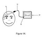
- FIG. 1Ais a schematic illustration of an embodiment of the sensor system in use.
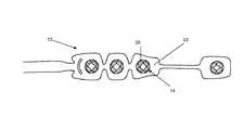
- FIG. 1Bis a top plan view of an embodiment of the sensor system
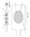
- FIG. 1Cis an enlarged perspective view of a skin preparation device incorporated in a sensor system.
- FIG. 2is a perspective view of one embodiment of a skin preparation device.
- FIG. 3Ais a perspective view of a second embodiment of a skin preparation device.
- FIG. 3Bis a top plan view of the second embodiment of the skin preparation device.
- FIG. 3Cis a front cross-sectional view of the embodiment of FIG. 3A .
- FIG. 3Dis a side cross-sectional view of the embodiment of FIG. 3A .
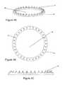
- FIG. 4Ais a perspective view of a third embodiment of the skin preparation device.
- FIG. 4Bis a top plan view of the embodiment of FIG. 4A .
- FIG. 4Cis a side view of the embodiment of FIG. 4A .
- FIG. 5Ais an enlarged perspective view of an embodiment of the tines of a skin preparation device.
- FIG. 5Bis a side view of the tines shown in FIG. 5A .
- FIG. 5Cis a front view of the tines shown in FIG. 5A .
- FIG. 6is a perspective view of an embodiment of a skin preparation device including a separate gel chamber.
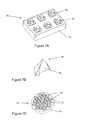
- FIG. 7Ais a perspective view of an embodiment of a skin preparation device.
- FIG. 7Bis an enlarged perspective view of a tine of the embodiment shown in FIG. 7A .
- FIG. 7Cis an alternate embodiment of the skin preparation device shown in FIG. 7A .
- a biopotential sensor 12 shown in FIGS. 1A and 1Bis a device that contains an array of one or more electrodes 14 and a set of conductors that provide an electrical conduction path for the acquired signals from the electrodes 14 to a single terminating connector 16 which in turn connects to the mating receptacle 18 of the biopotential monitoring system 20 .
- the sensor device 12may be coupled to the monitoring system via a terminating connector 16 inserted into a mating receptacle 18 on the monitoring system 20 . Once electrical connection is achieved, the monitoring system 20 may perform analysis of the acquired biopotential signals.
- the biopotential sensor 12includes one or more electrodes 14 .
- the sensor 12is comprised of four electrodes 14 .
- the sensor 12includes a flexible substrate 22 with an adhesive layer on at least portions of the substrate 22 to enable secure placement on the skin.
- the conductorswhich may be printed on the substrate 22 with conductive material or alternately be a set of conductive wires mounted on the substrate 22 , and the terminating connector which enables connection of the conductors to the monitoring system.
- the electrodes 14 that comprise the sensor 12may be formed with a layer of conductive material, preferably silver/silver chloride, which may be printed.
- the electrodesmay incorporate a silver/silver chloride coated surface in contact with a post or stud on the opposite (non-patient contacting) surface.
- the post or studmakes electrical contact via a common EEG snap or a pre-attached wire, between the electrode surface and the conductors to the connector.
- the conductive surface of the electrodemay also be formed of conductive carbon.
- the surface of the electrode 14may be coated with a conductive medium, preferably an ionic conductive wet gel, comparable to those commercially available for the application of signal acquisition.
- a solid conductive gelmay be used to coat the surface of the electrode 14 .
- the conductive gelmay be both a conductive medium as well as an adhesive. The conductive gel provides continuous contact between the electrode surface and the surface of the skin even if the electrode substrate does not conform precisely to the curvature of the electrode site on the skin.
- the electrode 14 areamay contain a sponge to keep the electrolytic gel in suspension.
- a prepping devicewhich is an array 26 of rigid tines 24 .
- the tine array 26may be affixed to the electrode(s) 14 with an adhesive either on the bottom surface of the tine array 26 base or around its perimeter.
- the tine array 26may be positioned such that a portion of the length of the tines 24 in a tine array 26 extends above the adhesive layer which may be on the flexible sensor substrate 22 .
- the tine array 26is not part of an array of electrodes 14 , but instead is a separate component that is utilized to prepare the skin.
- the rigid tines 24may remain in contact with the skin and still remain affixed to the electrode surface once the electrode 14 with the prepping device on the sensor 12 has been pressed firmly against the skin.
- the tines 24may retract from the skin once pressure is no longer being applied.
- pressing the electrode 14 toward the skinallows the tine structure to displace or penetrate the stratum corneum and allows the bioelectrical signal to be conducted from the skin to the electrode surface by way of the conductive gel in which the tines are embedded.
- the conductive gelmay be applied to the top surface of the tine array 26 or alternately it may be contained in a sponge which may overlay the tines.
- a preferred tine heightis 0.020′′-0.040′′, however the tine height may range from 0.010′′-0.080′′, ensuring that the tine will efficiently create micro-conduits through the depth of the stratum corneum, while at the same time limiting the amount of deformation of the skin.
- the decreased height of the tine 24 in combination with small tine sizeminimizes sensation on the skin during the process of prepping the sensor 12 .
- An adhesive layerwhich could be adhesive backed foam, on the perimeter of the electrode 14 may be employed to create a central cavity in which the tine disk is secured.
- the small size of the tines 24 and the reduced number of timesallow the electrode 14 to be worn comfortably for long periods of time.
- the application proceduredoes not require specialized training and thus can be performed by any person, including self preparation by the subject of the biopotential recording. Furthermore, it eliminates the need for initial skin preparation by separate abrasive materials or gels prior to electrode application.
- the rigid tine array 26is formed from a non-conductive material. This same nonconductive material is used to form both the base of the tine array and the tine structures 24 themselves.
- the tine array materialis deposited with conductive particles, such as gold, silver or carbon, to make the part conductive and allow for direct electrode conduction through the structure.
- Each rigid tine array 26may have multiple identical or unique tine structures ranging in quantity from 20-60 tines per array. The spacing between the tines 24 is such that the tine array 26 can be adequately machined or molded. For manufacturability, the tines 24 may be aligned in rows or a circular pattern and the orientation of the individual tines 24 may vary. Alternate embodiments may contain tines numbering anywhere between 10 and 100 per array.
- tines of various heightsmay be advantageous to reducing “bed of nails” effect when trying to obtain low skin impedances in certain parts of the body.
- the differing tine heightsmay avoid the disadvantage of distributing the applied pressure evenly between identical length tines and thus being unable to pierce the stratum corneum.
- the base of the tine array 26may be flat, convex, or any geometry such that the base conforms to the shape of the skin at the electrode application site. Alternately, the base may be formed in multiple stepped levels 28 as shown in FIG. 2 to allow better displacement or penetration of the stratum corneum at more pliable areas of the skin.
- the tines 24are formed on the top surface of the array base.
- the base 30 of the array 26is a round disk with a diameter in the range of 0.25′′-0.50′′, however it may range in size from 0.10′′-1.0′′.
- the shape of the base 30 of the array 26may also be created in any size and geometry such that the tine array 26 fits within the area of the electrode 14 .
- the base 30 of the tine array 26may be solid or may contain one or more holes or channels 32 . The holes or channels will allow the passage of conductive gel from the surface of the skin to the surface of the electrode.
- FIG. 4AAn alternate embodiment of the arrangement of the tine array shown in FIG. 4A to 4C is a solid annular ring 36 which contains the tines 24 and which includes a central opening 38 to permit gel flow and electrical contact between the conductive medium and the electrode surface ( FIG. 4A ).
- Yet another alternate embodimenthas a small round tine array that leaves an outer ring of the electrode surface exposed.
- Alternate embodimentsmay contain electrode surfaces up to 1.5′′ in diameter.
- the gelmay be contained in a separate cavity during storage and gets displaced to the skin site during application or during the prepping action ( FIG. 6 ).
- the tine structureis preferably created from a plastic such as polycarbonate (PC), acrylonitrile butadiene styrene (ABS), nylon, etc., through the process of injection molding.
- the tine structureis created from liquid crystal polymer (LCP), such as Vectra E130i manufactured by Ticona Engineering Polymers, Florence, Ky.
- LCPliquid crystal polymer
- the materialmay alternatively be any nonconductive plastic which is rigid, such that the tips do not bend upon contact with the skin; however, this material, as applied to the structure, must not be brittle, in order to prevent breakage of the tips in the skin.
- the entire tine array structuremay be created through injection molding using the same material in a single piece for both the base 30 and individual tines 24 .
- the tine arraymay be assembled from multiple molded pieces.
- the use of nonconductive materialensures that offset voltages are not created by contact between metal and skin.
- the preferred manufacturing methodis injection molding due to repeatability and low cost of mass production and the preferred array shape of a disk is optimal for efficiency of injection molding techniques.
- the tine array 26may be formed by machining, etching or printing methods.
- An alternate embodimentmay include the impregnation of the molded material with carbon nanotubes in order to increase the hardness of the tines 24 .
- the carbon nanotubesmay also make the electrode surface partly conductive, which aids in signal acquisition.
- each individual tine 24is generally tapered from base to tip and protrudes in a perpendicular direction from the base.
- the tip of each tine 24penetrates approximately at a 90 degree angle to the skin upon pressing of the electrode against the surface of the skin. Rigid, perpendicular penetration effectively creates repeatable micro-conduits in the stratum corneum with the least force required.
- the geometry, including the aspect ratio of the tineis determined to optimize the sharpness of the tip, the effectiveness of skin penetration and the manufacturability of the device.
- the sharpness of the tip of the tine 24can be quantified as a radius of curvature.
- the tines 24 in the arrays 26have a radius of curvature less than 0.02′′.
- the height of an individual tinemay be in the range of 0.010′′-0.080′′ though the preferred height is in the range of 0.020′′-0.040′′.
- the preferred geometry of the tine 24is that of a triangular pyramid with an isosceles triangle shaped base.
- the base of the triangular pyramidmay also be an equilateral or scalene triangle.
- the geometry of the tine 24may be various other shapes which allow for a taper from base to tip such as a rectangular pyramid, a half cone with a semicircular base or a full cone with a full circle or an elliptical base, or the tine 24 can be in the shape of an obelisk where the taper does not necessarily begin at the base of the tine.
- one face of the pyramidpreferably the face corresponding to the longest side of the triangle may extend at a 90 degree angle from the base.
- the cross section of such a tinewould be a right-angled triangle having one side as vertical, that is, perpendicular to the base.
- Impedance measurements at the skin interfacewere obtained with a biopotential sensor consisting of an array of four (4) electrodes (in an arrangement as shown in FIG. 1B ) each including an embodiment of the rigid tine device.
- This embodiment of the tine deviceconsisted of an array of twenty four (24) pyramidal tines at 0.030′′ in height, and with a sharp point having a radius of curvature less than 0.01′′.
- the measurementsaveraged 7 k ⁇ with less than 2.6 k ⁇ standard deviation across subjects.
- Each electrode area 14contains multiple tine arrays 26 which are arranged over a layer of conductive material.
- the prepping structures or tine arrays 26are arranged on the individual electrodes 14 such that a substructure is created with independent prepping areas.
- the tine arrays 26approach the skin at different angles. The angulations of the individual tine arrays 26 accommodate skin irregularities in certain areas of the body or in the softer tissue areas.
- an exemplary gel storage container or chamber 50is shown coupled to a prepping device 60 .
- the gel storage containermay be a burst container.
- the burst containeris designed to open upon the application of force.
- the gel storage container 50will hold the conductive gel separate from the electrode and prepping mechanism until the sensor is applied to a patient's skin. This will aid in a longer shelf life for the sensor since any dryout by the conductive gel will be avoided during storage.
- the gel storage container 50is shown with a ring prepping mechanism, however, the gel storage container may be used in combination with any of the skin preparation mechanisms shown. In the illustrated embodiment of FIG.
- the prepping mechanismincludes a base member 62 that is contiguous with a plurality of generally pyramidal tines 64 .
- Each tine 64may have a concave side that is aligned with a curved sidewall of an aperture or hole 66 formed in the base member 62 of the prepping device 60 .
- the gel storage containeris designed such that applying pressure on the skin prepping device causes the gel to flow from the gel storage device through the aperture into the area between the prepping device and the skin. This serves to precisely place the gel at the site of the micro conduits created by the time arrays.
- the prepping device 70may include a plurality of holes or apertures 72 formed in a base member 74 .
- the base member 74is shown as rectangular in shape, but other shapes may be used.
- the base member 74may also include a plurality of tines 76 .
- Each tine 76is generally pyramidal in shape having a concave side wall. In the preferred embodiment, the concave sidewall is perpendicular to the base of the pyramid as shown in FIG. 7B .
- This tine construction of a pyramid with a perpendicular concave wallcreates a much sharper edge than a pyramid alone, as is evident by the smaller radius of the tip of the preferred construction in comparison to an equivalently-sized pyramid without a concave wall.
- the concave sidewall of the tine 76is aligned with a sidewall of one of the apertures 72 in the base member 74 .
- FIG. 7Ashows four tines 76 for each aperture 72 , any number of tines 76 may be provided for each aperture 72 .
- FIG. 7Ban enlarged drawing of a generally pyramidal tine 76 is shown.
- the concave sidewall 78is shown as extending from the apex of the pyramid through the base of the pyramid. This curved sidewall 78 may be aligned with an aperture formed in the base member 74 .
- FIG. 7Can alternate embodiment of a prepping device or mechanism 70 including the generally pyramidal tines 76 is shown.
- an exemplary tine patternis shown.
- the tines 76 in combination with the apertures 72is shown in a cross pattern. Any pattern using the combination of tines 76 and apertures 72 formed in the base member 74 may be used to form a prepping device or mechanism.
- the pattern shown hereis one example of a pattern that is contemplated.
Landscapes
- Health & Medical Sciences (AREA)
- Life Sciences & Earth Sciences (AREA)
- Engineering & Computer Science (AREA)
- Animal Behavior & Ethology (AREA)
- Veterinary Medicine (AREA)
- Public Health (AREA)
- Biomedical Technology (AREA)
- Heart & Thoracic Surgery (AREA)
- Medical Informatics (AREA)
- General Health & Medical Sciences (AREA)
- Surgery (AREA)
- Physics & Mathematics (AREA)
- Molecular Biology (AREA)
- Pathology (AREA)
- Biophysics (AREA)
- Dermatology (AREA)
- Anesthesiology (AREA)
- Hematology (AREA)
- Measurement And Recording Of Electrical Phenomena And Electrical Characteristics Of The Living Body (AREA)
- Electrotherapy Devices (AREA)
Abstract
Description
Claims (8)
Priority Applications (2)
| Application Number | Priority Date | Filing Date | Title |
|---|---|---|---|
| US12/435,028US8700122B2 (en) | 2008-05-02 | 2009-05-04 | Skin preparation device and biopotential sensor |
| US14/219,664US20140296683A1 (en) | 2008-05-02 | 2014-03-19 | Skin preparation device and biopotential sensor |
Applications Claiming Priority (2)
| Application Number | Priority Date | Filing Date | Title |
|---|---|---|---|
| US12684908P | 2008-05-02 | 2008-05-02 | |
| US12/435,028US8700122B2 (en) | 2008-05-02 | 2009-05-04 | Skin preparation device and biopotential sensor |
Related Child Applications (1)
| Application Number | Title | Priority Date | Filing Date |
|---|---|---|---|
| US14/219,664ContinuationUS20140296683A1 (en) | 2008-05-02 | 2014-03-19 | Skin preparation device and biopotential sensor |
Publications (2)
| Publication Number | Publication Date |
|---|---|
| US20100022864A1 US20100022864A1 (en) | 2010-01-28 |
| US8700122B2true US8700122B2 (en) | 2014-04-15 |
Family
ID=41255893
Family Applications (2)
| Application Number | Title | Priority Date | Filing Date |
|---|---|---|---|
| US12/435,028Active2031-05-10US8700122B2 (en) | 2008-05-02 | 2009-05-04 | Skin preparation device and biopotential sensor |
| US14/219,664AbandonedUS20140296683A1 (en) | 2008-05-02 | 2014-03-19 | Skin preparation device and biopotential sensor |
Family Applications After (1)
| Application Number | Title | Priority Date | Filing Date |
|---|---|---|---|
| US14/219,664AbandonedUS20140296683A1 (en) | 2008-05-02 | 2014-03-19 | Skin preparation device and biopotential sensor |
Country Status (3)
| Country | Link |
|---|---|
| US (2) | US8700122B2 (en) |
| EP (1) | EP2280645B1 (en) |
| WO (1) | WO2009135200A2 (en) |
Cited By (8)
| Publication number | Priority date | Publication date | Assignee | Title |
|---|---|---|---|---|
| US9538949B2 (en) | 2010-09-28 | 2017-01-10 | Masimo Corporation | Depth of consciousness monitor including oximeter |
| US20180049661A1 (en)* | 2016-03-29 | 2018-02-22 | CeriBell, Inc. | Methods and apparatus for electrode placement and tracking |
| US9901278B1 (en)* | 2010-05-25 | 2018-02-27 | Neurowave Systems Inc | Physiological electrode assembly for fast application |
| US20180192911A1 (en)* | 2017-01-10 | 2018-07-12 | Korea Electronics Technologies Institute | Sensors for measuring skin conductivity and methods for manufacturing the same |
| US10154815B2 (en) | 2014-10-07 | 2018-12-18 | Masimo Corporation | Modular physiological sensors |
| US11357434B2 (en) | 2018-05-31 | 2022-06-14 | CeriBell, Inc. | Adjustable geometry wearable electrodes |
| US12178580B2 (en) | 2019-12-23 | 2024-12-31 | Alimetry Limited | Electrode patch and connection system |
| US12186515B2 (en) | 2020-04-28 | 2025-01-07 | Ticona Llc | Microneedle assembly |
Families Citing this family (31)
| Publication number | Priority date | Publication date | Assignee | Title |
|---|---|---|---|---|
| US9610459B2 (en)* | 2009-07-24 | 2017-04-04 | Emkinetics, Inc. | Cooling systems and methods for conductive coils |
| US20100168501A1 (en)* | 2006-10-02 | 2010-07-01 | Daniel Rogers Burnett | Method and apparatus for magnetic induction therapy |
| US9339641B2 (en) | 2006-01-17 | 2016-05-17 | Emkinetics, Inc. | Method and apparatus for transdermal stimulation over the palmar and plantar surfaces |
| US20070167990A1 (en)* | 2006-01-17 | 2007-07-19 | Theranova, Llc | Method and apparatus for low frequency induction therapy for the treatment of urinary incontinence and overactive bladder |
| JP2010505471A (en)* | 2006-10-02 | 2010-02-25 | エムキネティクス, インコーポレイテッド | Method and apparatus for magnetic induction therapy |
| US10786669B2 (en) | 2006-10-02 | 2020-09-29 | Emkinetics, Inc. | Method and apparatus for transdermal stimulation over the palmar and plantar surfaces |
| US11224742B2 (en) | 2006-10-02 | 2022-01-18 | Emkinetics, Inc. | Methods and devices for performing electrical stimulation to treat various conditions |
| US9005102B2 (en) | 2006-10-02 | 2015-04-14 | Emkinetics, Inc. | Method and apparatus for electrical stimulation therapy |
| EP2493551A4 (en) | 2009-10-26 | 2013-04-17 | Emkinetics Inc | Method and apparatus for electromagnetic stimulation of nerve, muscle, and body tissues |
| DK2568878T3 (en) | 2010-05-12 | 2018-10-29 | Irhythm Tech Inc | Interior features and design elements for long-term adhesion |
| US8588884B2 (en)* | 2010-05-28 | 2013-11-19 | Emkinetics, Inc. | Microneedle electrode |
| US20130158482A1 (en)* | 2010-07-26 | 2013-06-20 | Seventh Sense Biosystems, Inc. | Rapid delivery and/or receiving of fluids |
| WO2012064802A1 (en) | 2010-11-09 | 2012-05-18 | Seventh Sense Biosystems, Inc. | Systems and interfaces for blood sampling |
| WO2012074576A1 (en)* | 2010-12-02 | 2012-06-07 | 3M Innovative Properties Company | Liquid crystalline polymer microneedles |
| AU2011349277A1 (en)* | 2010-12-22 | 2013-06-27 | Valeritas, Inc. | Microneedle patch applicator |
| CN102334989B (en)* | 2011-07-29 | 2013-03-27 | 上海交通大学 | Different-plane microneedle array brain electrical dry electrode with controllable puncturing depth |
| US20140296796A1 (en)* | 2011-11-02 | 2014-10-02 | Chee Yen Lim | Plastic microneedle strip |
| US9522267B2 (en)* | 2012-02-08 | 2016-12-20 | Derma Dream Group Ltd | Transdermal delivery device |
| GB2499595A (en)* | 2012-02-21 | 2013-08-28 | James Roche | Infant EEG electrode system |
| KR102145450B1 (en) | 2013-01-24 | 2020-08-18 | 아이리듬 테크놀로지스, 아이엔씨 | Physiological monitoring device |
| WO2014168841A1 (en)* | 2013-04-08 | 2014-10-16 | Irhythm Technologies, Inc | Skin abrader |
| WO2016070128A1 (en) | 2014-10-31 | 2016-05-06 | Irhythm Technologies, Inc. | Wireless physiological monitoring device and systems |
| ITUB20160311A1 (en)* | 2016-01-18 | 2017-07-18 | Rise Tech S R L | FLEXIBLE ELECTRODE FOR THE APPLICATION OF AN ELECTRIC FIELD TO THE HUMAN BODY |
| FR3058310B1 (en)* | 2016-11-09 | 2019-01-25 | Arioneo | CARDIO-FREQUENCEMETE ELECTRODE AND METHOD OF MEASURING HEART RATE |
| TW202110402A (en)* | 2019-07-26 | 2021-03-16 | 日商富士軟片股份有限公司 | Stethoscope |
| EP4103051A1 (en) | 2020-02-12 | 2022-12-21 | Irhythm Technologies, Inc. | Non-invasive cardiac monitor and methods of using recorded cardiac data to infer a physiological characteristic of a patient |
| CN115551583A (en)* | 2020-05-25 | 2022-12-30 | 考司美德制药株式会社 | High performance microneedle arrays |
| WO2022032118A1 (en) | 2020-08-06 | 2022-02-10 | Irhythm Technologies, Inc. | Electrical components for physiological monitoring device |
| US11350865B2 (en) | 2020-08-06 | 2022-06-07 | Irhythm Technologies, Inc. | Wearable device with bridge portion |
| US20220280051A1 (en)* | 2021-03-05 | 2022-09-08 | Arizona Board Of Regents On Behalf Of Arizona State University | In-ear wearable device |
| USD1063079S1 (en) | 2021-08-06 | 2025-02-18 | Irhythm Technologies, Inc. | Physiological monitoring device |
Citations (30)
| Publication number | Priority date | Publication date | Assignee | Title |
|---|---|---|---|---|
| US2727516A (en)* | 1953-03-19 | 1955-12-20 | Compule Corp | Medical sampling devices and specimen containers |
| US2943628A (en)* | 1957-02-27 | 1960-07-05 | William L Howell | Electrode assembly |
| US4685466A (en) | 1985-01-29 | 1987-08-11 | Rau Guenter | Measuring sensor for the non-invasive detection of electro-physiological quantities |
| US4709702A (en)* | 1985-04-25 | 1987-12-01 | Westinghouse Electric Corp. | Electroencephalographic cap |
| US5305746A (en) | 1992-09-29 | 1994-04-26 | Aspect Medical Systems, Inc. | Disposable, pre-gelled, self-prepping electrode |
| US5309909A (en) | 1992-05-22 | 1994-05-10 | Physio-Control Corporation | Combined skin preparation and monitoring electrode |
| US6032064A (en) | 1996-10-11 | 2000-02-29 | Aspect Medical Systems, Inc. | Electrode array system for measuring electrophysiological signals |
| US6136008A (en) | 1998-03-19 | 2000-10-24 | 3M Innovative Properties Company | Skin abrader for biomedical electrode |
| WO2001052731A1 (en) | 2000-01-21 | 2001-07-26 | Instrumentarium Corporation | Medical electrode |
| WO2002000096A2 (en) | 2000-06-23 | 2002-01-03 | Physiometrix, Inc. | Frontal electrode array for patient eeg signal acquisition |
| US6434410B1 (en)* | 1998-06-19 | 2002-08-13 | Aspect Medical Systems, Inc. | Electrode for measuring electrophysiological signals using liquid electrolytic gel with a high salt concentration |
| US6510333B1 (en) | 2000-05-16 | 2003-01-21 | Mark J. Licata | Sensor for biopotential measurements |
| US6622035B1 (en) | 2000-01-21 | 2003-09-16 | Instrumentarium Corp. | Electrode for measurement of weak bioelectrical signals |
| WO2004009172A1 (en) | 2002-07-19 | 2004-01-29 | 3M Innovative Properties Company | Microneedle devices and microneedle delivery apparatus |
| US6690959B2 (en) | 2000-09-01 | 2004-02-10 | Medtronic, Inc. | Skin-mounted electrodes with nano spikes |
| US6782283B2 (en) | 2001-09-07 | 2004-08-24 | Robert N. Schmidt | Dry penetrating recording device |
| US6785569B2 (en) | 2001-09-07 | 2004-08-31 | Orbital Research | Dry physiological recording electrode |
| US6961603B2 (en) | 2003-06-17 | 2005-11-01 | Instrumentarim Corp. | Unitary multi-electrode biopotential signal sensor and method for making same |
| JP2005334594A (en)* | 2004-05-27 | 2005-12-08 | I-Com:Kk | Drug administration patch with carbon nanotube protrusions |
| US7013179B2 (en) | 2000-01-07 | 2006-03-14 | Biowave Corporation | Percutaneous electrode array |
| US20060173261A1 (en) | 2005-01-31 | 2006-08-03 | Magnus Kall | Biopotential sensor |
| US7103398B2 (en) | 2000-11-01 | 2006-09-05 | 3M Innovative Properties Company | Electrical sensing and/or signal application device |
| WO2007075614A1 (en) | 2005-12-21 | 2007-07-05 | 3M Innovative Properties Company | Microneedle devices |
| WO2007081430A2 (en) | 2006-01-10 | 2007-07-19 | Yuzhakov Vadim V | Microneedle array, patch, and applicator for transdermal drug delivery |
| US20070276211A1 (en) | 2006-05-26 | 2007-11-29 | Jose Mir | Compact minimally invasive biomedical monitor |
| US7316671B2 (en)* | 2002-08-29 | 2008-01-08 | Becton, Dickinson And Company | Microprotrusion arrays and methods for using same to deliver substances into tissue |
| US20080009763A1 (en)* | 2006-06-09 | 2008-01-10 | Jin-Chern Chiou | Microprobe array structure and method for manufacturing the same |
| US20080139911A1 (en) | 2006-12-08 | 2008-06-12 | General Electric Company | Self-adhering electrodes and methods of making the same |
| US20080294031A1 (en)* | 2007-05-22 | 2008-11-27 | Persyst Development Corporation | Method and device for quick press on eeg electrode |
| US20090253975A1 (en)* | 2008-04-04 | 2009-10-08 | Mark Tiegs | ECG monitoring electrode |
Family Cites Families (2)
| Publication number | Priority date | Publication date | Assignee | Title |
|---|---|---|---|---|
| DK0921840T3 (en)* | 1996-07-03 | 2003-09-22 | Altea Therapeutics Corp | Multiple mechanical microperforation of skin or mucosa |
| US7611481B2 (en) | 2004-03-24 | 2009-11-03 | Corium International, Inc. | Transdermal delivery device |
- 2009
- 2009-05-04USUS12/435,028patent/US8700122B2/enactiveActive
- 2009-05-04EPEP09740002.2Apatent/EP2280645B1/enactiveActive
- 2009-05-04WOPCT/US2009/042684patent/WO2009135200A2/enactiveApplication Filing
- 2014
- 2014-03-19USUS14/219,664patent/US20140296683A1/ennot_activeAbandoned
Patent Citations (33)
| Publication number | Priority date | Publication date | Assignee | Title |
|---|---|---|---|---|
| US2727516A (en)* | 1953-03-19 | 1955-12-20 | Compule Corp | Medical sampling devices and specimen containers |
| US2943628A (en)* | 1957-02-27 | 1960-07-05 | William L Howell | Electrode assembly |
| US4685466A (en) | 1985-01-29 | 1987-08-11 | Rau Guenter | Measuring sensor for the non-invasive detection of electro-physiological quantities |
| US4709702A (en)* | 1985-04-25 | 1987-12-01 | Westinghouse Electric Corp. | Electroencephalographic cap |
| US5309909A (en) | 1992-05-22 | 1994-05-10 | Physio-Control Corporation | Combined skin preparation and monitoring electrode |
| US5305746A (en) | 1992-09-29 | 1994-04-26 | Aspect Medical Systems, Inc. | Disposable, pre-gelled, self-prepping electrode |
| US6032064A (en) | 1996-10-11 | 2000-02-29 | Aspect Medical Systems, Inc. | Electrode array system for measuring electrophysiological signals |
| US6136008A (en) | 1998-03-19 | 2000-10-24 | 3M Innovative Properties Company | Skin abrader for biomedical electrode |
| US6434410B1 (en)* | 1998-06-19 | 2002-08-13 | Aspect Medical Systems, Inc. | Electrode for measuring electrophysiological signals using liquid electrolytic gel with a high salt concentration |
| US7013179B2 (en) | 2000-01-07 | 2006-03-14 | Biowave Corporation | Percutaneous electrode array |
| WO2001052731A1 (en) | 2000-01-21 | 2001-07-26 | Instrumentarium Corporation | Medical electrode |
| US6622035B1 (en) | 2000-01-21 | 2003-09-16 | Instrumentarium Corp. | Electrode for measurement of weak bioelectrical signals |
| US20040054393A1 (en)* | 2000-01-21 | 2004-03-18 | Goran Stemme | Medical electrode |
| US6510333B1 (en) | 2000-05-16 | 2003-01-21 | Mark J. Licata | Sensor for biopotential measurements |
| WO2002000096A2 (en) | 2000-06-23 | 2002-01-03 | Physiometrix, Inc. | Frontal electrode array for patient eeg signal acquisition |
| US6690959B2 (en) | 2000-09-01 | 2004-02-10 | Medtronic, Inc. | Skin-mounted electrodes with nano spikes |
| US7103398B2 (en) | 2000-11-01 | 2006-09-05 | 3M Innovative Properties Company | Electrical sensing and/or signal application device |
| US6782283B2 (en) | 2001-09-07 | 2004-08-24 | Robert N. Schmidt | Dry penetrating recording device |
| US7032301B1 (en) | 2001-09-07 | 2006-04-25 | Orbital Research Inc | Dry physiological recording electrode |
| US7032302B1 (en) | 2001-09-07 | 2006-04-25 | Orbital Research Inc. | Dry physiological recording device |
| US6785569B2 (en) | 2001-09-07 | 2004-08-31 | Orbital Research | Dry physiological recording electrode |
| WO2004009172A1 (en) | 2002-07-19 | 2004-01-29 | 3M Innovative Properties Company | Microneedle devices and microneedle delivery apparatus |
| US7316671B2 (en)* | 2002-08-29 | 2008-01-08 | Becton, Dickinson And Company | Microprotrusion arrays and methods for using same to deliver substances into tissue |
| US6961603B2 (en) | 2003-06-17 | 2005-11-01 | Instrumentarim Corp. | Unitary multi-electrode biopotential signal sensor and method for making same |
| JP2005334594A (en)* | 2004-05-27 | 2005-12-08 | I-Com:Kk | Drug administration patch with carbon nanotube protrusions |
| US20060173261A1 (en) | 2005-01-31 | 2006-08-03 | Magnus Kall | Biopotential sensor |
| WO2007075614A1 (en) | 2005-12-21 | 2007-07-05 | 3M Innovative Properties Company | Microneedle devices |
| WO2007081430A2 (en) | 2006-01-10 | 2007-07-19 | Yuzhakov Vadim V | Microneedle array, patch, and applicator for transdermal drug delivery |
| US20070276211A1 (en) | 2006-05-26 | 2007-11-29 | Jose Mir | Compact minimally invasive biomedical monitor |
| US20080009763A1 (en)* | 2006-06-09 | 2008-01-10 | Jin-Chern Chiou | Microprobe array structure and method for manufacturing the same |
| US20080139911A1 (en) | 2006-12-08 | 2008-06-12 | General Electric Company | Self-adhering electrodes and methods of making the same |
| US20080294031A1 (en)* | 2007-05-22 | 2008-11-27 | Persyst Development Corporation | Method and device for quick press on eeg electrode |
| US20090253975A1 (en)* | 2008-04-04 | 2009-10-08 | Mark Tiegs | ECG monitoring electrode |
Non-Patent Citations (5)
| Title |
|---|
| Griss, P. et al., "Micromachined Electrodes for Biopotential Measurements," J. MicroElectroMech. Sys., vol. 10(1): 10-16 (2001). |
| International Search Report issued for PCT/US09/042684, dated Dec. 1, 2009 (3 pages). |
| Microelectrode Arrays, Cyberkinetics-Neurotechnology Systems, Inc., dated Mar. 16, 2005 (2 pages), accessed from http://www.cyberkineticsinc.com/content/researchproducts/microelectrodearrays.jsp. |
| Ng, W.C., et al., "Micro-spike EEG electrode and the vacuum-casting technology for mass production," J. Mater. Process. Tech., doi:10.1016/j.jmatprotec.2008.10.051, (5 pages) (2009). |
| Sivamani, R.K. et al., "Microneedles and transdermal applications," Expert Opin. Drug Deliv., 4(1): 19-25 (2007). |
Cited By (20)
| Publication number | Priority date | Publication date | Assignee | Title |
|---|---|---|---|---|
| US11039774B1 (en)* | 2010-05-25 | 2021-06-22 | NeuroWave Systems, Inc. | Physiological electrode assembly for fast application |
| US12070317B1 (en)* | 2010-05-25 | 2024-08-27 | Neurowave Systems Inc. | Physiological electrode assembly for fast application |
| US9901278B1 (en)* | 2010-05-25 | 2018-02-27 | Neurowave Systems Inc | Physiological electrode assembly for fast application |
| US11717210B2 (en) | 2010-09-28 | 2023-08-08 | Masimo Corporation | Depth of consciousness monitor including oximeter |
| US9538949B2 (en) | 2010-09-28 | 2017-01-10 | Masimo Corporation | Depth of consciousness monitor including oximeter |
| US10531811B2 (en) | 2010-09-28 | 2020-01-14 | Masimo Corporation | Depth of consciousness monitor including oximeter |
| US10154815B2 (en) | 2014-10-07 | 2018-12-18 | Masimo Corporation | Modular physiological sensors |
| US10765367B2 (en) | 2014-10-07 | 2020-09-08 | Masimo Corporation | Modular physiological sensors |
| US11717218B2 (en) | 2014-10-07 | 2023-08-08 | Masimo Corporation | Modular physiological sensor |
| US10888240B2 (en)* | 2016-03-29 | 2021-01-12 | CeriBell, Inc. | Methods and apparatus for electrode placement and tracking |
| US12324670B2 (en) | 2016-03-29 | 2025-06-10 | CeriBell, Inc. | Methods and apparatus for electrode placement and tracking |
| US20180049661A1 (en)* | 2016-03-29 | 2018-02-22 | CeriBell, Inc. | Methods and apparatus for electrode placement and tracking |
| US12150769B2 (en) | 2016-03-29 | 2024-11-26 | CeriBell, Inc. | Methods and apparatus for electrode placement and tracking |
| US12336826B2 (en) | 2016-03-29 | 2025-06-24 | CeriBell, Inc. | Methods and apparatus for electrode placement and tracking |
| US10786175B2 (en)* | 2017-01-10 | 2020-09-29 | Korea Electronics Technology Institute | Sensors for measuring skin conductivity and methods for manufacturing the same |
| US20180192911A1 (en)* | 2017-01-10 | 2018-07-12 | Korea Electronics Technologies Institute | Sensors for measuring skin conductivity and methods for manufacturing the same |
| US11357434B2 (en) | 2018-05-31 | 2022-06-14 | CeriBell, Inc. | Adjustable geometry wearable electrodes |
| US12245862B2 (en) | 2019-12-23 | 2025-03-11 | Alimetry Limited | Electrode patch and connection system |
| US12178580B2 (en) | 2019-12-23 | 2024-12-31 | Alimetry Limited | Electrode patch and connection system |
| US12186515B2 (en) | 2020-04-28 | 2025-01-07 | Ticona Llc | Microneedle assembly |
Also Published As
| Publication number | Publication date |
|---|---|
| US20100022864A1 (en) | 2010-01-28 |
| US20140296683A1 (en) | 2014-10-02 |
| EP2280645A4 (en) | 2013-09-18 |
| WO2009135200A2 (en) | 2009-11-05 |
| EP2280645A2 (en) | 2011-02-09 |
| EP2280645B1 (en) | 2015-03-18 |
| WO2009135200A3 (en) | 2010-02-18 |
Similar Documents
| Publication | Publication Date | Title |
|---|---|---|
| US8700122B2 (en) | Skin preparation device and biopotential sensor | |
| US7941201B2 (en) | Microprobe array structure and method for manufacturing the same | |
| US8201330B1 (en) | Physiological recording device or electrode | |
| EP1164928B1 (en) | Method of fabricating a medical electrode | |
| US11039774B1 (en) | Physiological electrode assembly for fast application | |
| US10959632B1 (en) | Physiological recording device or electrode | |
| EP1086719B1 (en) | Device for abrading skin | |
| US6961603B2 (en) | Unitary multi-electrode biopotential signal sensor and method for making same | |
| Ghane-Motlagh et al. | Design and implementation challenges of microelectrode arrays: a review | |
| EP2788075B1 (en) | Device for reducing patient transthoracic impedance | |
| JP3963485B2 (en) | Minimal intrusion detection device | |
| EP1792565A1 (en) | Selectively exposable miniature probes with integrated sensor arrays for continuous in vivo diagnostics | |
| KR101785287B1 (en) | Microneedle electrode patch and fabrication method of the microneedle electrode patch | |
| CN114144114A (en) | Body monitoring system comprising microneedles | |
| MXPA00005761A (en) | Device for enhancing transdermal agent flux |
Legal Events
| Date | Code | Title | Description |
|---|---|---|---|
| AS | Assignment | Owner name:ASPECT MEDICAL SYSTEMS, INC., MASSACHUSETTS Free format text:ASSIGNMENT OF ASSIGNORS INTEREST;ASSIGNORS:CORDERO, RAFAEL M.;HARHEN, ROBERT;KINNEY, MELISSA;AND OTHERS;SIGNING DATES FROM 20090702 TO 20090723;REEL/FRAME:023331/0124 Owner name:ASPECT MEDICAL SYSTEMS, INC., MASSACHUSETTS Free format text:ASSIGNMENT OF ASSIGNORS INTEREST;ASSIGNORS:CORDERO, RAFAEL M.;HARHEN, ROBERT;KINNEY, MELISSA;AND OTHERS;REEL/FRAME:023331/0124;SIGNING DATES FROM 20090702 TO 20090723 | |
| AS | Assignment | Owner name:NELLCOR PURITAN BENNETT LLC, MISSOURI Free format text:ASSIGNMENT OF ASSIGNORS INTEREST;ASSIGNOR:ASPECT MEDICAL SYSTEMS, LLC;REEL/FRAME:024065/0482 Effective date:20091225 Owner name:ASPECT MEDICAL SYSTEMS, LLC, MASSACHUSETTS Free format text:MERGER;ASSIGNOR:ASPECT MEDICAL SYSTEMS, INC.;REEL/FRAME:024065/0368 Effective date:20091223 Owner name:NELLCOR PURITAN BENNETT LLC,MISSOURI Free format text:ASSIGNMENT OF ASSIGNORS INTEREST;ASSIGNOR:ASPECT MEDICAL SYSTEMS, LLC;REEL/FRAME:024065/0482 Effective date:20091225 Owner name:ASPECT MEDICAL SYSTEMS, LLC,MASSACHUSETTS Free format text:MERGER;ASSIGNOR:ASPECT MEDICAL SYSTEMS, INC.;REEL/FRAME:024065/0368 Effective date:20091223 | |
| AS | Assignment | Owner name:COVIDIEN LP, MASSACHUSETTS Free format text:ASSIGNMENT OF ASSIGNORS INTEREST;ASSIGNOR:NELLCOR PURITAN BENNETT LLC;REEL/FRAME:029431/0511 Effective date:20120929 | |
| STCF | Information on status: patent grant | Free format text:PATENTED CASE | |
| MAFP | Maintenance fee payment | Free format text:PAYMENT OF MAINTENANCE FEE, 4TH YEAR, LARGE ENTITY (ORIGINAL EVENT CODE: M1551) Year of fee payment:4 | |
| MAFP | Maintenance fee payment | Free format text:PAYMENT OF MAINTENANCE FEE, 8TH YEAR, LARGE ENTITY (ORIGINAL EVENT CODE: M1552); ENTITY STATUS OF PATENT OWNER: LARGE ENTITY Year of fee payment:8 | |
| MAFP | Maintenance fee payment | Free format text:PAYMENT OF MAINTENANCE FEE, 12TH YEAR, LARGE ENTITY (ORIGINAL EVENT CODE: M1553); ENTITY STATUS OF PATENT OWNER: LARGE ENTITY Year of fee payment:12 |