US8699982B2 - Systems and methods for implementing a distributed antenna system in a radio frequency integrated circuit - Google Patents
Systems and methods for implementing a distributed antenna system in a radio frequency integrated circuitDownload PDFInfo
- Publication number
- US8699982B2 US8699982B2US13/430,863US201213430863AUS8699982B2US 8699982 B2US8699982 B2US 8699982B2US 201213430863 AUS201213430863 AUS 201213430863AUS 8699982 B2US8699982 B2US 8699982B2
- Authority
- US
- United States
- Prior art keywords
- uplink
- downlink
- signal
- integrated circuit
- synthesizer
- Prior art date
- Legal status (The legal status is an assumption and is not a legal conclusion. Google has not performed a legal analysis and makes no representation as to the accuracy of the status listed.)
- Active, expires
Links
Images


Classifications
- H—ELECTRICITY
- H04—ELECTRIC COMMUNICATION TECHNIQUE
- H04W—WIRELESS COMMUNICATION NETWORKS
- H04W88/00—Devices specially adapted for wireless communication networks, e.g. terminals, base stations or access point devices
- H04W88/08—Access point devices
- H04W88/085—Access point devices with remote components
Definitions
- the antenna unitincludes an uplink integrated circuit, wherein the uplink integrated circuit receives a radio frequency signal.
- the uplink integrated circuitincludes an uplink synthesizer configured to provide an uplink oscillating signal in at least one frequency; an uplink mixer stage coupled to the uplink synthesizer, the uplink mixer stage configured to mix the uplink radio frequency signal with the uplink oscillating signal to produce an uplink intermediate frequency signal; and an uplink control interface configured to receive uplink commands that control the frequency of the uplink oscillating signal.
- the antenna unitfurther includes a downlink integrated circuit that is electrically isolated from the uplink integrated circuit, wherein the downlink integrated circuit receives a downlink intermediate frequency signal.
- the downlink integrated circuitincludes a downlink synthesizer configured to provide a downlink oscillating signal in at least one frequency; a downlink mixer stage coupled to the downlink synthesizer, the downlink mixer stage configured to mix the downlink intermediate frequency signal with the downlink oscillating signal to produce a down link radio frequency signal; a downlink control interface configured to receive downlink commands that control the frequency of the downlink oscillating signal.
- the antenna unitalso includes at least one clock configured to provide at least one reference frequency to the uplink synthesizer and the downlink synthesizer.
- FIG. 1is a block diagram of one embodiment of a distributed antenna system, where the remote antenna units include radio frequency integrated circuits.
- FIG. 2is a block diagram of one embodiment of a downlink integrated circuit in an RAU.
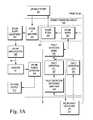
- FIGS. 3A and 3Bare a block diagram of one embodiment of an uplink integrated circuit in an RAU.
- FIG. 4is a flow diagram of a method for consolidating multiple components of an RAU onto integrated circuits according to one embodiment.
- Embodiments described in the present applicationlimit the space consumed by multiple electronic components of an RAU by consolidating elements onto integrated circuits (ICs).
- the multiple electronic components of an RAUare placed onto two separate ICs.
- Electronic components associated with the downlink functionality of the RAUare placed on a downlink IC while electronic components associated with the uplink functionality of the RAU are placed on an uplink IC.
- the uplink IC and the downlink ICinclude components for generating oscillating signals in multiple frequency bands and for mixing a received intermediate frequency signal up to a radio frequency, in the case of the downlink IC, or mixing a received radio frequency signal down to an intermediate frequency, in the case of the uplink IC.
- the consolidation of components onto the two ICssaves space while allowing for the reception and transmission of signals in multiple frequency bands.
- FIG. 1illustrates an exemplary embodiment of a communication network 100 .
- communication network 100includes a base station 102 , which is communicatively coupled to a distributed antenna system (DAS) 101 .
- DAS 101transports communication signals between one or more upstream devices (for example, base station 102 , wireless access points, or other sources of communication signals) and one or more downstream wireless devices (for example, a wireless terminal 140 such as a cellular phone).
- upstream devicesfor example, base station 102 , wireless access points, or other sources of communication signals
- downstream wireless devicesfor example, a wireless terminal 140 such as a cellular phone.
- Base station 102manages communication among wireless terminals 140 and between wireless terminals 140 and other communication networks that are coupled to base station 102 .
- base station 102manages communication between wireless terminals 140 and a public switched telephone network (PSTN).
- PSTNpublic switched telephone network
- communication network 100is a cellular/PCS system and base station 102 communicates with a base station controller which acts as a voice/PSTN gateway to the PSTN.
- base station 102manages communication between wireless terminals 140 and an internet protocol (IP)-based network (such as the internet via communication with an IP gateway).
- IPinternet protocol
- base station 102performs baseband processing on IP data from an IP gateway and places the IP data onto a channel.
- base station 102is an IEEE 802.16 compliant base station.
- base station 102may also meet the requirements of WiMax, WiBro, LTE, or other consortium.
- base station 102comprises multiple functionalities including managing communications between both a PSTN and an IP-based network.
- DAS 101comprises a host unit 104 communicatively coupled to base station 102 .
- Host unit 104provides an interface through which DAS 101 can be controlled and configured by a user.
- host unit 104is communicatively coupled with a hub unit 106 .
- the host unit 104is coupled to multiple hub units 106 .
- hub unit 106receives a digital signal from host unit 104 and converts the digital signal into an analog signal for transmission to a RAU 108 .
- host unit 104converts a digital signal into an analog signal for transmission to hub unit 106 , which hub unit 106 then repeats and splits the signal for transmission to multiple RAUs 108 .
- RAUs 108receive signals from hub unit 106 and transmit the signals to wireless terminals 140 through remote antennas 110 .
- a wireless terminal 140transmits information that is received by the RAU 108 that is communicating with the transmitting wireless terminal 140 through a remote antenna 110 attached to the RAU 108 .
- RAU 108reproduces the signal received from wireless terminal 140 and sends the signal along with other signals received from other wireless terminals 140 transmitting to RAU 108 to hub unit 106 .
- Hub unit 106receives information from RAU 108 , reproduces the signals received and sends the signals to base station 102 through host unit 104 .
- Base station 102processes the information and transmits the information toward its destination. In the downlink direction, incoming information from another network is received by base station 102 .
- Base station 102determines which of wireless terminals 140 is the destination of the information, generates, modulates, and transmits a signal containing the information to hub unit 106 through host unit 104 .
- Hub unit 106receives the signal, reproduces the signal, and sends the signal to the RAU 108 that is in communication with the destination wireless terminal 140 .
- RAU 108receives the signal from hub unit 106 , reproduces the signal, and sends the signal wirelessly to wireless terminal 140 , where the information is received and processed.
- RAU 108upconverts signals received from hub unit 106 from an intermediate frequency (IF) signal to a radio frequency (RF) signal for transmission to a wireless terminal 140 . Further, RAU 108 downconverts signals received from wireless terminals 140 from an RF signal to an IF signal for transmission to hub unit 106 . To perform the upconversion and downconversion of both received IF and RF signals, RAU includes both downlink circuitry to perform the conversion from IF to RF and uplink circuitry to convert an RF signal into an IF signal. In at least one embodiment, a portion of the uplink circuitry and a portion of the downlink circuitry are implemented as integrated circuits.
- the portion of the uplink circuitryis implemented as uplink IC 130 and the portion of the downlink circuitry is implemented as downlink IC 120 .
- the uplink circuitry and downlink circuitryare implemented as two separate integrated circuits in order to isolate electrical signals that pass through the uplink IC 130 from electrical signals that pass through the downlink IC 120 .
- uplink IC 130includes an uplink mixer stage 132 and an uplink synthesizer 134 .
- Uplink mixer stage 132receives an RF signal from wireless terminal 140 .
- uplink mixer stage 132downconverts the RF signal to an IF signal.
- the IF signalis then transmitted to the hub unit 106 .
- uplink mixer stage 132receives an oscillating signal from uplink synthesizer 134 .
- Uplink synthesizer 134is a section of hardware in uplink IC 130 that produces an oscillating signal that uplink mixer stage 132 uses as a the mixing signal to downconvert the RF signal into the IF signal.
- downlink IC 120includes a downlink mixer stage 122 and a downlink synthesizer 124 .
- Downlink mixer stage 122receives an IF signal from hub unit 106 .
- downlink mixer stage 122upconverts the IF signal to an RF signal.
- the RF signalis then transmitted to a wireless terminal 140 through a remote antenna 110 .
- downlink mixer stage 122receives an oscillating signal from downlink synthesizer 124 .
- Downlink synthesizer 124is a section of hardware in downlink IC 120 that produces an oscillating signal that downlink mixer stage 122 uses as a the mixing signal to upconvert the IF signal into the RF signal.
- the downlink mixer stage 122 and the downlink synthesizer 124are electrically isolated from one another on downlink IC 120 .
- the downlink mixer stage 122 and downlink synthesizer 124are electrically isolated from one another to prevent electrical signals that pass through downlink mixer stage 122 and downlink synthesizer 124 from inadvertently affecting one another.
- uplink IC 130is able to receive and downlink IC 120 is able to transmit RF signals in a variety of frequency bands.
- uplink IC 130is able to receive and downlink IC 120 is able to transmit RF signals in frequency bands that include Cell, IDEN800, EGSM, IDEN900, PCS, DCS, UMTS, 700UC, 700ABC, AWS, or the like.
- uplink IC 130is able to receive RF signals that are within the frequency range 690 MHz to 2000 MHz.
- uplink IC 130is able to transmit IF signals that are within the frequency range of 40 MHz to 650 MHz.
- downlink IC 120is able to receive IF signals that are within the frequency range of 40 MHz to 650 MHz and transmit RF signals that are within the frequency range of 700 MHz to 2200 MHz.
- both uplink synthesizer 134 and downlink synthesizer 124provide oscillating signals in a wide range of frequencies to uplink mixer stage 132 and downlink mixer stage 122 .
- uplink synthesizer 134provides an oscillating signal to uplink mixer stage 132 in the frequency range of 750 MHz to 2600 MHz.
- downlink synthesizer 124provides an oscillating signal to downlink mixer stage 122 in the frequency range of 590 MHz to 2600 MHz.
- both uplink mixer stage 132 and downlink mixer stage 122provide high side and low side mixing.
- both uplink IC 130 and downlink IC 120receive uplink commands and downlink commands through uplink control interface 136 and downlink control interface 126 respectively.
- the uplink and downlink commandsare sent to uplink IC 130 and downlink IC 120 from an external computer or controlling device.
- RAUs 108include a microcontroller that sends uplink and downlink commands to uplink control interface 136 and downlink control interface 126 .
- uplink mixer stage 132 and uplink synthesizer 134By consolidating uplink mixer stage 132 and uplink synthesizer 134 on to a single uplink IC 130 , while allowing an external device to control the operation of uplink IC 130 through uplink control interface 136 , and consolidating similar components on to a single downlink IC 120 , the components of RAUs 108 occupy less space within the RAUs 108 and enable the controlling of both receiving and transmitting RF and IF signals from RAUs 108 .
- FIG. 2is a block diagram illustrating one embodiment of the downlink IC 220 along with supporting electronic components.
- Downlink IC 220functions similarly to downlink IC 120 in FIG. 1 .
- downlink IC 220includes downlink mixer stage 222 , downlink synthesizer 224 , and downlink control interface 226 , which are similar to downlink mixer stage 122 , downlink synthesizer 124 , and downlink control interface 126 .
- the IF signalis received by a downlink IF amplifier 207 , which amplifies the IF signal.
- the downlink IC 220transmits the signal to a downlink IF filter 217 which attenuates, filters, and adjusts the slope of the IF signal.
- downlink IF filter 217includes a series of attenuation pads, a surface acoustic wave filter, and an adjustable slope circuit.
- the downlink IF filter 217transmits the IF signal back to downlink IC 220 , where the signal is received by downlink mixer stage 222 .
- downlink mixer stage 222includes a downlink IF variable gain attenuator (VGA) 201 .
- VGAdownlink IF variable gain attenuator
- downlink IF VGA 201is able to provide a gain of up to 30 dB and can be adjusted in 1 dB steps.
- an off chip component or external computercan adjust the gain of downlink IF VGA 201 through downlink commands transmitted through downlink control interface 226 .
- downlink IF VGA 201attenuates the gain of the IF signal
- downlink IF VGA 201transmits the attenuated IF signal to downlink mixer 203 .
- Downlink mixer 203receives a downlink oscillating signal from downlink synthesizer 224 and uses the oscillating signal to mix the amplified IF signal up to RF to form the RF signal. When downlink mixer 203 upconverts the IF signal to the RF signal, the RF signal is then transmitted to a downlink RF VGA 205 .
- Downlink RF VGA 205functions similarly to downlink IF VGA 201 , in that the attenuation provided by downlink RF VGA 205 is controlled by an off chip component or by an external computer through downlink control interface 226 . For example, downlink RF VGA 205 responds to a digital signal that adjusts the gain of downlink RF VGA 205 between 0 and 10 dB when amplifying the RF signal.
- the RF signalis transmitted off downlink IC 220 to a downlink RF filter 219 .
- downlink RF filter 219includes attenuation pads and a surface acoustic wave filter to filter the mixed signal for transmission to a wireless terminal.
- the downlink RF filter 219transmits the signal back to the downlink IC 220 .
- Downlink IC 220receives the filtered RF signal and directs the filtered RF signal to a downlink RF amplifier 209 .
- Downlink RF amplifier 209amplifies the RF signal and the signal is then transmitted off the board for further amplification 221 before the RF signal is transmitted through a remote antenna such as remote antenna 110 in FIG. 1 .
- the downlink mixer stage 222receives an oscillating signal that is produced by downlink synthesizer 224 .
- Downlink synthesizer 224produces the oscillating signal from a clock 229 or other device for producing a reference frequency.
- clock 229when producing a reference frequency, is able to provide multiple reference frequencies.
- clock 229provides reference frequencies of 10.7 MHz or 30.72 MHz.
- the Downlink synthesizer 224receives the reference frequency with downlink reference amplifier 216 .
- Downlink reference amplifier 216amplifies the reference frequency for use in creating an oscillating signal.
- reference amplifier 216also squares the reference frequency signal to create a low jitter squarewave.
- the downlink reference amplifier 216passes the amplified reference frequency to downlink phase locked loop (PLL) 211 .
- Downlink PLL 211adjusts the phase of the amplified reference frequency as necessary and transmits the adjusted reference frequency off the downlink IC to a downlink synthesizer low pass filter (LPF) 227 .
- the downlink synthesizer LPF 227filters the adjusted reference frequency and passes the filtered reference frequency to downlink switchable voltage controlled oscillator (VCO) 213 .
- VCOvoltage controlled oscillator
- Downlink switchable VCO 213receives downlink commands through downlink control interface 226 that direct VCO 213 to provide the oscillating signal with the needed frequency for accurately mixing the IF signal to the desired RF signal.
- the downlink switchable VCO 213provides an oscillating signal that is combined with a corrective signal transmitted from downlink PLL 211 to provide the oscillating signal that is used by downlink mixer 203 .
- a downlink command received through downlink control interface 226can disable downlink synthesizer 224 .
- downlink mixer 203receives an oscillating signal from a local oscillator that is located off of downlink integrated circuit 220 .
- the frequency provided by the downlink switchable VCO 213changes such that the downlink PLL 211 is able to lock the frequency.
- downlink integrated circuit 220includes a downlink power detector 215 .
- Downlink power detector 215monitors the power from an RF input 223 .
- downlink power detector 215is a root mean square (RMS) detector that detects the power reflected from an antenna port on the RAU within a range up to 35 dB.
- RMSroot mean square
- a downlink commandwill disable portions of the downlink IC 220 to prevent the reflected power from damaging the portions of the downlink IC.
- a downlink commandcan disable the downlink RF amplifier 209 .
- the downlink power detector 215transmits the measured power as an output voltage 225 .
- the output voltageis received by a microcontroller.
- downlink IC 220includes a downlink control interface 226 .
- downlink control interface 226is a SPI wire interface that allows an external device to control the different components that are on downlink IC 220 .
- an external devicecan send downlink commands through downlink control interface that set the frequency of the oscillating signal.
- the downlink commandscan disable components on downlink IC 220 .
- a downlink commandcan disable downlink RF amplifier 209 when downlink power detector 215 detects an RF input 223 that is higher than a test threshold.
- the external device connected to downlink IC 220 through downlink control interface 226is a microcontroller 231 that is part of the RAU.
- the external deviceis a computer that connects to the RAU and to downlink control interface 226 on the RAU.
- FIGS. 3A and 3Bis a block diagram illustrating one embodiment of the uplink IC 330 along with supporting electronic components.
- Uplink IC 330functions similarly to uplink IC 130 in FIG. 1 .
- uplink IC 330includes uplink mixer stage 332 , uplink synthesizer 334 , and uplink control interface 336 , which are similar to uplink mixer stage 132 , uplink synthesizer 134 , and uplink control interface 136 , respectively.
- uplink mixer stage 332receives an RF signal
- the RF signalis received by an uplink low noise amplifier (LNA) 343 , which amplifies the RF signal.
- LNAuplink low noise amplifier
- uplink IC 330transmits the amplified signal to an uplink RF filter 365 which attenuates and filters the amplified RF signal.
- uplink RF filter 365includes a series of attenuation pads and a surface acoustic wave filter.
- VVAvariable voltage attenuator
- Uplink VVA 341adjusts the voltage to achieve a desired RF signal and then transmits the RF signal to a balun 363 , which balances the signal. Balun 363 then transmits the signal back to uplink IC 330 , where the signal is received by uplink mixer stage 332 .
- uplink mixer stage 332includes an uplink RF VGA 339 .
- uplink RF VGA 339is able to provide a gain between 0 and 10 dB when amplifying the RF signal.
- an off chip component or external computercan adjust the gain of uplink RF VGA 339 through uplink commands transmitted through uplink control interface 336 .
- uplink RF VGA 339transmits the attenuated RF signal to uplink mixer 337 .
- Uplink mixer 337receives an uplink oscillating signal from uplink synthesizer 334 and uses the oscillating signal to mix the amplified RF signal down to IF to form an IF signal. When uplink mixer 337 downconverts the RF signal to the IF signal, the IF signal is then transmitted to an uplink IF VGA 335 .
- Uplink IF VGA 335functions similarly to uplink RF VGA 339 , in that the attenuation provided by uplink IF VGA 335 is controlled by an off chip component or by an external computer through downlink control interface 336 . For example, uplink IF VGA 335 responds to a digital signal that adjusts the gain of uplink IF VGA 335 up to 30 dB in 1 dB steps when amplifying the IF signal.
- the uplink IF VGA 335When, the uplink IF VGA 335 amplifies the IF signal, the IF signal is transmitted off uplink IC 330 to an uplink IF filter 361 .
- uplink IF filter 361includes attenuation pads and a surface acoustic wave filter to filter the IF signal.
- the uplink IF filter 361transmits the signal back to the uplink IC 330 .
- Uplink IC 330receives the filtered IF signal and directs the filtered IF signal to an uplink IF amplifier 333 .
- Uplink IF amplifier 333amplifies the IF signal and the signal is then transmitted off the board for uplink slope adjustment 367 and further uplink amplification 369 before the IF signal is transmitted to a hub unit such as hub unit 106 in FIG. 1 .
- the uplink mixer stage 332receives an oscillating signal that is produced by uplink synthesizer 334 .
- Uplink synthesizer 334produces the oscillating signal from a clock 379 or other device for producing a reference frequency.
- clock 379is able to provide multiple reference frequencies.
- clock 379 and clock 229 in FIG. 2are a single clock located in the RAU. Alternatively, clock 379 and clock 229 operated independently of one another in the RAU.
- the uplink synthesizer 334receives the reference frequency with synthesizer reference amplifier 355 .
- Synthesizer reference amplifier 355amplifies the reference frequency. In at least one implementation, reference amplifier 355 also squares the reference frequency signal to create a low jitter square wave. When synthesizer reference amplifier 355 amplifies the reference frequency, the synthesizer reference amplifier 355 passes the amplified reference frequency to synthesizer PLL 353 . Synthesizer PLL 353 adjusts the phase of the amplified reference frequency as necessary and transmits the adjusted reference frequency of the uplink IC 330 to an uplink synthesizer LPF 381 . The uplink synthesizer LPF 381 filters adjusted reference frequency and passes the filtered reference frequency to synthesizer switchable VCO 357 .
- Synthesizer switchable VCO 357receives uplink commands through uplink control interface 336 that direct synthesizer switchable VCO 357 to provide the oscillating signal with the needed frequency for accurately mixing the RF signal down to the desired IF signal.
- the synthesizer switchable VCO 357provides an oscillating signal that is combined with a corrective signal transmitted from synthesizer PLL 353 to provide the oscillating signal that is used by uplink mixer 337 .
- an uplink command received through uplink control interface 336can disable uplink synthesizer 334 . When uplink synthesizer 334 is disabled, uplink mixer 337 receives an oscillating signal from a local oscillator that is located off of uplink integrated circuit 330 .
- synthesizer PLL 353loses frequency lock, the frequency provided by the synthesizer switchable VCO 357 changes such that the synthesizer PLL 353 is able to lock the frequency.
- uplink IC 330includes components that aid in the detection of faults in the uplink path.
- uplink IC 330includes fault detection VCO 351 , fault detection PLL 347 , and fault detection reference amplifier 349 .
- the fault detection reference amplifier 349receives a reference frequency from clock 379 .
- Fault detection reference amplifier 349amplifies the reference frequency.
- the fault detection reference amplifier 349passes the amplified reference frequency to fault detection PLL 347 .
- Fault detection PLL 347adjusts the phase of the amplified reference frequency as necessary and transmits the adjusted frequency to an uplink fault detection LPF 377 .
- the uplink fault detection LPF 377filters adjusted reference frequency and passes the filtered reference frequency to fault detection switchable VCO 351 .
- the fault detection switchable VCO 351provides a fault detecting signal that is combined with a corrective signal transmitted from fault detection PLL 347 and transmitted to a fault detection mixer 345 .
- Fault detection mixer 345also receives an oscillating signal from uplink synthesizer 334 and mixes the oscillating signal with the fault detecting signal to generate a tone that indicates that a fault has been detected in the uplink path.
- an uplink command received through uplink control interface 336can disable or enable the detection of faults in the uplink path. Further, in at least one example, the detections of faults in the uplink path is enabled during the performance of a system test.
- uplink integrated circuit 330includes an uplink power detector 359 .
- the signal transmitted from uplink amplification 369is sent through a coupler 371 which transmits a signal to uplink power detector 359 , which monitors the power that is transmitted to upstream devices from the RAU containing uplink IC 330 .
- the uplink power detector 359transmits the measured power as an output voltage 373 .
- the output voltageis received by a microcontroller.
- uplink IC 330includes an uplink control interface 336 .
- uplink control interface 336is an SPI wire interface that allows an external device to control the different components that are on uplink IC 330 .
- an external devicecan send uplink commands through uplink control interface that set the frequency of the oscillating signal.
- the uplink commandscan disable components on uplink IC 330 .
- an uplink commandcan enable the detection of faults in the uplink path when a system test is performed.
- the external device connected to uplink IC 330 through uplink control interface 336is a microcontroller 375 that is part of the RAU.
- microcontroller 375 and microcontroller 231 in FIG. 2are the same device.
- the external deviceis a computer that connects to the RAU and to uplink control interface 336 on the RAU.
- FIG. 4is a flow diagram illustrating a method 400 for consolidating multiple components of a remote antenna unit onto integrated circuits.
- Method 400begins at 402 where an uplink integrated circuit is formed, wherein the uplink integrated circuit receives an uplink radio frequency signal and mixes the uplink radio frequency signal into an uplink intermediate frequency signal.
- uplink integrated circuitmixes the uplink radio frequency signal into an uplink intermediate frequency signal using an uplink synthesizer, an uplink mixer stage coupled to the uplink synthesizer, and an uplink control interface, which are similar to uplink mixer stage 332 , uplink synthesizer 334 , and uplink control interface 336 described above in relation to FIGS. 3A and 3B .
- Method 400proceeds at 404 where a downlink integrated circuit is formed, wherein the downlink integrated circuit receives a downlink intermediate frequency signal and mixes the downlink intermediate frequency signal into a downlink radio frequency signal.
- downlink integrated circuitmixes the downlink intermediate frequency signal into a downlink radio frequency signal using a downlink synthesizer, a downlink mixer stage coupled to the downlink synthesizer, and a downlink control interface, which are similar to downlink mixer stage 222 , downlink synthesizer 224 , and downlink control interface 226 described above in relation to FIG. 2 .
- the downlink integrated circuit and the uplink integrated circuitare fabricated using a silicon germanium process.
- Example 1includes a remote antenna unit in a distributed antenna system, the antenna unit comprising an uplink integrated circuit, wherein the uplink integrated circuit receives a radio frequency signal, the uplink integrated circuit comprising an uplink synthesizer configured to provide an uplink oscillating signal in at least one frequency; an uplink mixer stage coupled to the uplink synthesizer, the uplink mixer stage configured to mix the uplink radio frequency signal with the uplink oscillating signal to produce an uplink intermediate frequency signal; and an uplink control interface configured to receive uplink commands that control the frequency of the uplink oscillating signal; the antenna unit further comprising a downlink integrated circuit that is electrically isolated from the uplink integrated circuit, wherein the downlink integrated circuit receives a downlink intermediate frequency signal, the downlink integrated circuit comprising a downlink synthesizer configured to provide a downlink oscillating signal in at least one frequency; a downlink mixer stage coupled to the downlink synthesizer, the downlink mixer stage configured to mix the downlink intermediate frequency signal with the downlink oscillating signal to
- Example 2includes the remote antenna unit of Example 1, wherein the uplink mixer stage comprises an uplink radio frequency variable gain attenuator, wherein the gain of the uplink radio frequency variable gain attenuator is set by the uplink commands; an uplink mixer configured to mix the uplink radio frequency signal with the uplink oscillating signal to produce an uplink intermediate frequency signal; and an uplink intermediate frequency variable gain attenuator, wherein the gain of the uplink intermediate frequency variable gain attenuator is set by the uplink commands.
- the uplink mixer stagecomprises an uplink radio frequency variable gain attenuator, wherein the gain of the uplink radio frequency variable gain attenuator is set by the uplink commands
- an uplink mixerconfigured to mix the uplink radio frequency signal with the uplink oscillating signal to produce an uplink intermediate frequency signal
- an uplink intermediate frequency variable gain attenuatorwherein the gain of the uplink intermediate frequency variable gain attenuator is set by the uplink commands.
- Example 3includes the remote antenna unit of Example 2, wherein the uplink mixer performs both low-side mixing and high-side mixing.
- Example 4includes the remote antenna unit of any of Examples 1-3, wherein the uplink synthesizer comprises a synthesizer switchable voltage controlled oscillator configured to respond to the uplink commands by providing the uplink oscillating signal, wherein the uplink commands set the frequency of the uplink oscillating signal; and a synthesizer phase lock loop configured to adjust the phase of the uplink oscillating signal.
- the uplink synthesizercomprises a synthesizer switchable voltage controlled oscillator configured to respond to the uplink commands by providing the uplink oscillating signal, wherein the uplink commands set the frequency of the uplink oscillating signal; and a synthesizer phase lock loop configured to adjust the phase of the uplink oscillating signal.
- Example 5includes the remote antenna unit of any of Examples 1-4, wherein the uplink control interface disables the uplink synthesizer in response to an uplink command, whereupon the uplink mixer receives the uplink oscillating signal from a device located off of the uplink integrated circuit.
- Example 6includes the remote antenna unit of any of Examples 1-5, wherein the uplink integrated circuit further comprises an uplink intermediate frequency amplifier configured to amplify the uplink intermediate frequency signal.
- Example 7includes the remote antenna unit of any of Examples 1-6, wherein the uplink integrated circuit further comprises an uplink radio frequency variable voltage attenuator configured to attenuate the uplink radio frequency signal in response to an uplink command received over the uplink control interface.
- the uplink integrated circuitfurther comprises an uplink radio frequency variable voltage attenuator configured to attenuate the uplink radio frequency signal in response to an uplink command received over the uplink control interface.
- Example 8includes the remote antenna unit of any of Examples 1-7, wherein the uplink integrated circuit further comprises an uplink low noise amplifier configured to amplify the uplink radio frequency signal while limiting noise introduced into the uplink radio frequency signal.
- the uplink integrated circuitfurther comprises an uplink low noise amplifier configured to amplify the uplink radio frequency signal while limiting noise introduced into the uplink radio frequency signal.
- Example 9includes the remote antenna unit of any of Examples 1-8, wherein the uplink integrated circuit further comprises an uplink power detector configured to detect the power of the uplink intermediate frequency signal before the uplink intermediate frequency signal is transmitted to upstream devices.
- the uplink integrated circuitfurther comprises an uplink power detector configured to detect the power of the uplink intermediate frequency signal before the uplink intermediate frequency signal is transmitted to upstream devices.
- Example 10includes the remote antenna unit of any of Examples 1-9, wherein the uplink integrated circuit further includes fault detection components configured to detect a fault in the uplink path through the remote antenna unit, wherein the fault detection components generate a tone for fault detection.
- Example 11includes the remote antenna unit of Example 10, wherein the fault detection components comprise a fault detection switchable voltage controlled oscillator configured to respond to an uplink command by providing a fault detection oscillating signal, wherein the uplink commands set the frequency of the fault detection oscillating signal; and a fault detection phase lock loop configured to adjust the phase of the fault detection oscillating signal; and a fault detection mixer configured to mix the fault detection oscillating signal with the uplink oscillating signal to generate a fault detection tone.
- the fault detection componentscomprise a fault detection switchable voltage controlled oscillator configured to respond to an uplink command by providing a fault detection oscillating signal, wherein the uplink commands set the frequency of the fault detection oscillating signal; and a fault detection phase lock loop configured to adjust the phase of the fault detection oscillating signal; and a fault detection mixer configured to mix the fault detection oscillating signal with the uplink oscillating signal to generate a fault detection tone.
- Example 12includes the remote antenna unit of any of Examples 1-11, wherein the downlink mixer stage comprises a downlink intermediate frequency variable gain attenuator configured to attenuate the downlink intermediate frequency signal, wherein the gain of the downlink intermediate frequency variable gain attenuator is set by the downlink commands; a downlink mixer configured to mix the downlink radio frequency signal with the downlink oscillating signal to produce a downlink intermediate frequency signal; and a downlink radio frequency variable gain attenuator configured to attenuate the downlink radio frequency signal, wherein the gain of the downlink radio frequency variable gain attenuator is set by the downlink commands.
- the downlink mixer stagecomprises a downlink intermediate frequency variable gain attenuator configured to attenuate the downlink intermediate frequency signal, wherein the gain of the downlink intermediate frequency variable gain attenuator is set by the downlink commands;
- Example 13includes the remote antenna unit Example 12, wherein the downlink mixer performs both low-side mixing and high-side mixing.
- Example 14includes the remote antenna unit of any of Examples 1-13, wherein the downlink synthesizer comprises a downlink switchable voltage controlled oscillator configured to respond to the downlink commands by providing the downlink oscillating signal, wherein the downlink commands set the frequency of the downlink oscillating signal; and a synthesizer phase lock loop configured to adjust the phase of the uplink oscillating signal.
- the downlink synthesizercomprises a downlink switchable voltage controlled oscillator configured to respond to the downlink commands by providing the downlink oscillating signal, wherein the downlink commands set the frequency of the downlink oscillating signal; and a synthesizer phase lock loop configured to adjust the phase of the uplink oscillating signal.
- Example 15includes the remote antenna unit of any of Examples 1-14, wherein the downlink control interface disables the downlink synthesizer in response to the downlink commands, whereupon the downlink mixer stage receives the downlink oscillating signal from a device located off of the downlink integrated circuit.
- Example 17includes the remote antenna unit of any of Examples 1-16, wherein the downlink integrated circuit further comprises a downlink radio frequency amplifier configured to amplify the downlink radio frequency signal.
- Example 18includes the remote antenna unit of any of Examples 1-17, wherein the downlink integrated circuit further comprises a downlink power detector configured to detect the power of the downlink radio frequency signal before the downlink radio frequency signal is transmitted to an antenna for transmission.
- the downlink integrated circuitfurther comprises a downlink power detector configured to detect the power of the downlink radio frequency signal before the downlink radio frequency signal is transmitted to an antenna for transmission.
- Example 19includes the remote antenna unit of any of Examples 1-18, further comprising a microcontroller configured to issue uplink commands to the uplink integrated circuit and downlink commands to the downlink integrated circuit.
- Example 20includes the remote antenna unit of any of Examples 1-19, wherein the remote antenna unit includes uplink supporting circuitry configured to support the operation of the uplink integrated circuit, wherein the uplink supporting circuitry comprises an uplink intermediate frequency filter configured to filter the uplink intermediate frequency signal; a balun configured to balance the uplink radio frequency signal; an uplink radio frequency filter configured to filter the uplink radio frequency signal; and an uplink synthesizer low pass filter configured to filter a reference frequency for the uplink synthesizer.
- the uplink supporting circuitrycomprises an uplink intermediate frequency filter configured to filter the uplink intermediate frequency signal; a balun configured to balance the uplink radio frequency signal; an uplink radio frequency filter configured to filter the uplink radio frequency signal; and an uplink synthesizer low pass filter configured to filter a reference frequency for the uplink synthesizer.
- Example 21includes the remote antenna unit of any of Examples 1-20, wherein the remote antenna unit includes downlink supporting circuitry configured to support the operation of the downlink integrated circuit, wherein the downlink supporting circuitry comprises a downlink intermediate frequency filter configured to filter the downlink intermediate frequency signal; a downlink radio frequency filter configured to filter the downlink radio frequency signal; and a downlink synthesizer low pass filter configured to filter a reference frequency for the downlink synthesizer.
- the remote antenna unitincludes downlink supporting circuitry configured to support the operation of the downlink integrated circuit, wherein the downlink supporting circuitry comprises a downlink intermediate frequency filter configured to filter the downlink intermediate frequency signal; a downlink radio frequency filter configured to filter the downlink radio frequency signal; and a downlink synthesizer low pass filter configured to filter a reference frequency for the downlink synthesizer.
- Example 22includes a method for consolidating multiple components of a remote antenna unit onto integrated circuits, the method comprising forming an uplink integrated circuit, wherein the uplink integrated circuit receives an uplink radio frequency signal and mixes the uplink radio frequency signal into an uplink intermediate frequency signal, wherein the uplink radio frequency signal has a frequency in one of a plurality of uplink frequency bands; and forming a downlink integrated circuit that is electrically isolated from the uplink integrated circuit, wherein the downlink integrated circuit receives a downlink intermediate frequency signal and mixes the downlink intermediate frequency signal into a downlink radio frequency signal, wherein the downlink radio frequency signal has a frequency in one of a plurality of downlink frequency bands.
- Example 23includes the method of Example 22, further comprising providing filtering and attenuation to support the operation of the uplink integrated circuit and the downlink integrated circuit.
- Example 24includes the method of any of Examples 22-23, further comprising providing a reference frequency source to transmit at least one reference frequency to the downlink integrated circuit and the uplink integrated circuit.
- Example 25includes the method of any of Examples 22-24, further comprising providing a microcontroller configured to transmit downlink commands to the downlink integrated circuit and uplink commands to the uplink integrated circuit.
- Example 26includes the method of any of Examples 22-25, wherein the uplink integrated circuit and the downlink integrated circuit are formed using a silicon germanium process.
- Example 27includes a distributed antenna system, the system comprising: at least one hub unit configured to communicate with a base station; a plurality of remote antenna units communicatively coupled to the at least one hub and configured to communicatively couple signals between the at least one hub and a plurality of wireless terminals, a remote antenna unit in the plurality of remote antenna units comprising an uplink integrated circuit, wherein the uplink integrated circuit receives a radio frequency signal, the uplink integrated circuit comprising an uplink synthesizer configured to provide an uplink oscillating signal in at least one frequency; an uplink mixer stage coupled to the uplink synthesizer, the uplink mixer stage configured to mix the radio frequency signal with the uplink oscillating signal to produce an uplink intermediate frequency signal; and an uplink control interface configured to receive uplink commands that control the frequency of the uplink oscillating signal; the remote antenna unit also comprising a downlink integrated circuit that is electrically isolated from the uplink integrated circuit, wherein the downlink integrated circuit receives a downlink intermediate frequency signal, the downlink integrated circuit
- Example 28includes the distributed antenna system of Example 27, wherein the uplink synthesizer, and the uplink mixer stage are located in the integrated circuit such that uplink synthesizer is electrically isolated from the uplink mixer stage.
- Example 29includes the distributed antenna system of any of Examples 27-28, wherein the downlink synthesizer, and the downlink mixer stage are located in the integrated circuit such that uplink synthesizer is electrically isolated from the uplink mixer stage.
- Example 30includes the distributed antenna system of any of Examples 27-29, wherein the uplink mixer stage comprises an uplink radio frequency variable gain attenuator, wherein the gain of the uplink radio frequency variable gain attenuator is set by the uplink commands; an uplink mixer configured to mix the uplink radio frequency signal with the uplink oscillating signal to produce an uplink intermediate frequency signal; and an uplink intermediate frequency variable gain attenuator, wherein the gain of the uplink intermediate frequency variable gain attenuator is set by the uplink commands.
- the uplink mixer stagecomprises an uplink radio frequency variable gain attenuator, wherein the gain of the uplink radio frequency variable gain attenuator is set by the uplink commands; an uplink mixer configured to mix the uplink radio frequency signal with the uplink oscillating signal to produce an uplink intermediate frequency signal; and an uplink intermediate frequency variable gain attenuator, wherein the gain of the uplink intermediate frequency variable gain attenuator is set by the uplink commands.
- Example 31includes the distributed antenna system of any of Examples 27-30, wherein the uplink synthesizer comprises a synthesizer switchable voltage controlled oscillator configured to respond to the uplink commands by providing the uplink oscillating signal, wherein the uplink commands set the frequency of the uplink oscillating signal; and a synthesizer phase lock loop configured to adjust the phase of the uplink oscillating signal.
- the uplink synthesizercomprises a synthesizer switchable voltage controlled oscillator configured to respond to the uplink commands by providing the uplink oscillating signal, wherein the uplink commands set the frequency of the uplink oscillating signal; and a synthesizer phase lock loop configured to adjust the phase of the uplink oscillating signal.
- Example 32includes the distributed antenna system of any of Examples 27-31, wherein the uplink control interface disables the uplink synthesizer in response to an uplink command, whereupon the uplink mixer receives the uplink oscillating signal from a device located off of the uplink integrated circuit.
- Example 33includes the distributed antenna system of any of Examples 27-32, wherein the uplink integrated circuit further comprises an uplink power detector configured to detect the power of the uplink intermediate frequency signal before the uplink intermediate frequency signal is transmitted to upstream devices.
- the uplink integrated circuitfurther comprises an uplink power detector configured to detect the power of the uplink intermediate frequency signal before the uplink intermediate frequency signal is transmitted to upstream devices.
- Example 34includes the distributed antenna system of any of Examples 27-33, wherein the uplink integrated circuit further includes fault detection components configured to detect a fault in the uplink path through the remote antenna unit, wherein the fault detection components generate a tone for fault detection.
- Example 35includes the distributed antenna system Example 34, wherein the fault detection components comprise a fault detection switchable voltage controlled oscillator configured to respond to an uplink command by providing a fault detection oscillating signal, wherein the uplink commands set the frequency of the fault detection oscillating signal; and a fault detection phase lock loop configured to adjust the phase of the fault detection oscillating signal; and a fault detection mixer configured to mix the fault detection oscillating signal with the uplink oscillating signal to generate a fault detection tone.
- the fault detection componentscomprise a fault detection switchable voltage controlled oscillator configured to respond to an uplink command by providing a fault detection oscillating signal, wherein the uplink commands set the frequency of the fault detection oscillating signal; and a fault detection phase lock loop configured to adjust the phase of the fault detection oscillating signal; and a fault detection mixer configured to mix the fault detection oscillating signal with the uplink oscillating signal to generate a fault detection tone.
- Example 36includes the distributed antenna system of any of Examples 27-35, wherein the downlink mixer stage comprises a downlink intermediate frequency variable gain attenuator configured to attenuate the downlink intermediate frequency signal, wherein the gain of the downlink intermediate frequency variable gain attenuator is set by the downlink commands; a downlink mixer configured to mix the downlink radio frequency signal with the downlink oscillating signal to produce a downlink intermediate frequency signal; and a downlink radio frequency variable gain attenuator configured to attenuate the downlink radio frequency signal, wherein the gain of the downlink radio frequency variable gain attenuator is set by the downlink commands.
- the downlink mixer stagecomprises a downlink intermediate frequency variable gain attenuator configured to attenuate the downlink intermediate frequency signal, wherein the gain of the downlink intermediate frequency variable gain attenuator is set by the downlink commands;
- Example 37includes the distributed antenna system of any of Examples 27-36, wherein the downlink synthesizer comprises a downlink switchable voltage controlled oscillator configured to respond to the downlink commands by providing the downlink oscillating signal, wherein the downlink commands set the frequency of the downlink oscillating signal; and a synthesizer phase lock loop configured to adjust the phase of the uplink oscillating signal.
- the downlink synthesizercomprises a downlink switchable voltage controlled oscillator configured to respond to the downlink commands by providing the downlink oscillating signal, wherein the downlink commands set the frequency of the downlink oscillating signal; and a synthesizer phase lock loop configured to adjust the phase of the uplink oscillating signal.
- Example 38includes the distributed antenna system of any of Examples 27-37, wherein the downlink control interface disables the downlink synthesizer in response to the downlink commands, whereupon the downlink mixer stage receives the downlink oscillating signal from a device located off of the downlink integrated circuit.
- Example 39includes the distributed antenna system of any of Examples 27-38, wherein the downlink integrated circuit further comprises a downlink power detector configured to detect the power of the downlink radio frequency signal before the downlink radio frequency signal is transmitted to an antenna for transmission.
- the downlink integrated circuitfurther comprises a downlink power detector configured to detect the power of the downlink radio frequency signal before the downlink radio frequency signal is transmitted to an antenna for transmission.
- Example 40includes the distributed antenna system of any of Examples 27-39, further comprising a microcontroller configured to issue uplink commands to the uplink integrated circuit and downlink commands to the downlink integrated circuit.
Landscapes
- Engineering & Computer Science (AREA)
- Computer Networks & Wireless Communication (AREA)
- Signal Processing (AREA)
- Transceivers (AREA)
Abstract
Description
Claims (40)
Priority Applications (1)
| Application Number | Priority Date | Filing Date | Title |
|---|---|---|---|
| US13/430,863US8699982B2 (en) | 2012-03-27 | 2012-03-27 | Systems and methods for implementing a distributed antenna system in a radio frequency integrated circuit |
Applications Claiming Priority (1)
| Application Number | Priority Date | Filing Date | Title |
|---|---|---|---|
| US13/430,863US8699982B2 (en) | 2012-03-27 | 2012-03-27 | Systems and methods for implementing a distributed antenna system in a radio frequency integrated circuit |
Publications (2)
| Publication Number | Publication Date |
|---|---|
| US20130260706A1 US20130260706A1 (en) | 2013-10-03 |
| US8699982B2true US8699982B2 (en) | 2014-04-15 |
Family
ID=49235658
Family Applications (1)
| Application Number | Title | Priority Date | Filing Date |
|---|---|---|---|
| US13/430,863Active2032-11-30US8699982B2 (en) | 2012-03-27 | 2012-03-27 | Systems and methods for implementing a distributed antenna system in a radio frequency integrated circuit |
Country Status (1)
| Country | Link |
|---|---|
| US (1) | US8699982B2 (en) |
Cited By (27)
| Publication number | Priority date | Publication date | Assignee | Title |
|---|---|---|---|---|
| US9219879B2 (en) | 2009-11-13 | 2015-12-22 | Corning Optical Communications LLC | Radio-over-fiber (ROF) system for protocol-independent wired and/or wireless communication |
| US9240835B2 (en) | 2011-04-29 | 2016-01-19 | Corning Optical Communications LLC | Systems, methods, and devices for increasing radio frequency (RF) power in distributed antenna systems |
| US9253003B1 (en) | 2014-09-25 | 2016-02-02 | Corning Optical Communications Wireless Ltd | Frequency shifting a communications signal(S) in a multi-frequency distributed antenna system (DAS) to avoid or reduce frequency interference |
| US9258052B2 (en) | 2012-03-30 | 2016-02-09 | Corning Optical Communications LLC | Reducing location-dependent interference in distributed antenna systems operating in multiple-input, multiple-output (MIMO) configuration, and related components, systems, and methods |
| US9319138B2 (en) | 2010-02-15 | 2016-04-19 | Corning Optical Communications LLC | Dynamic cell bonding (DCB) for radio-over-fiber (RoF)-based networks and communication systems and related methods |
| US9325429B2 (en) | 2011-02-21 | 2016-04-26 | Corning Optical Communications LLC | Providing digital data services as electrical signals and radio-frequency (RF) communications over optical fiber in distributed communications systems, and related components and methods |
| US9338823B2 (en) | 2012-03-23 | 2016-05-10 | Corning Optical Communications Wireless Ltd | Radio-frequency integrated circuit (RFIC) chip(s) for providing distributed antenna system functionalities, and related components, systems, and methods |
| US9420542B2 (en) | 2014-09-25 | 2016-08-16 | Corning Optical Communications Wireless Ltd | System-wide uplink band gain control in a distributed antenna system (DAS), based on per band gain control of remote uplink paths in remote units |
| US9455784B2 (en) | 2012-10-31 | 2016-09-27 | Corning Optical Communications Wireless Ltd | Deployable wireless infrastructures and methods of deploying wireless infrastructures |
| US9525488B2 (en) | 2010-05-02 | 2016-12-20 | Corning Optical Communications LLC | Digital data services and/or power distribution in optical fiber-based distributed communications systems providing digital data and radio frequency (RF) communications services, and related components and methods |
| US9525472B2 (en) | 2014-07-30 | 2016-12-20 | Corning Incorporated | Reducing location-dependent destructive interference in distributed antenna systems (DASS) operating in multiple-input, multiple-output (MIMO) configuration, and related components, systems, and methods |
| US9531452B2 (en) | 2012-11-29 | 2016-12-27 | Corning Optical Communications LLC | Hybrid intra-cell / inter-cell remote unit antenna bonding in multiple-input, multiple-output (MIMO) distributed antenna systems (DASs) |
| US9730228B2 (en) | 2014-08-29 | 2017-08-08 | Corning Optical Communications Wireless Ltd | Individualized gain control of remote uplink band paths in a remote unit in a distributed antenna system (DAS), based on combined uplink power level in the remote unit |
| US9729267B2 (en) | 2014-12-11 | 2017-08-08 | Corning Optical Communications Wireless Ltd | Multiplexing two separate optical links with the same wavelength using asymmetric combining and splitting |
| US9775123B2 (en) | 2014-03-28 | 2017-09-26 | Corning Optical Communications Wireless Ltd. | Individualized gain control of uplink paths in remote units in a distributed antenna system (DAS) based on individual remote unit contribution to combined uplink power |
| US9813229B2 (en) | 2007-10-22 | 2017-11-07 | Corning Optical Communications Wireless Ltd | Communication system using low bandwidth wires |
| US10014944B2 (en) | 2010-08-16 | 2018-07-03 | Corning Optical Communications LLC | Remote antenna clusters and related systems, components, and methods supporting digital data signal propagation between remote antenna units |
| US10096909B2 (en) | 2014-11-03 | 2018-10-09 | Corning Optical Communications Wireless Ltd. | Multi-band monopole planar antennas configured to facilitate improved radio frequency (RF) isolation in multiple-input multiple-output (MIMO) antenna arrangement |
| US10110308B2 (en) | 2014-12-18 | 2018-10-23 | Corning Optical Communications Wireless Ltd | Digital interface modules (DIMs) for flexibly distributing digital and/or analog communications signals in wide-area analog distributed antenna systems (DASs) |
| US10128951B2 (en) | 2009-02-03 | 2018-11-13 | Corning Optical Communications LLC | Optical fiber-based distributed antenna systems, components, and related methods for monitoring and configuring thereof |
| US10135533B2 (en) | 2014-11-13 | 2018-11-20 | Corning Optical Communications Wireless Ltd | Analog distributed antenna systems (DASS) supporting distribution of digital communications signals interfaced from a digital signal source and analog radio frequency (RF) communications signals |
| US10187151B2 (en) | 2014-12-18 | 2019-01-22 | Corning Optical Communications Wireless Ltd | Digital-analog interface modules (DAIMs) for flexibly distributing digital and/or analog communications signals in wide-area analog distributed antenna systems (DASs) |
| US20200112372A1 (en)* | 2017-05-23 | 2020-04-09 | Mitsubishi Electric Corporation | Base station apparatus, ground station device, and ground antenna device |
| US10659163B2 (en) | 2014-09-25 | 2020-05-19 | Corning Optical Communications LLC | Supporting analog remote antenna units (RAUs) in digital distributed antenna systems (DASs) using analog RAU digital adaptors |
| US10805811B2 (en)* | 2017-12-18 | 2020-10-13 | Commscope Technologies Llc | Synchronization and fault management in a distributed antenna system |
| US11139892B2 (en) | 2018-10-01 | 2021-10-05 | Commscope Technologies Llc | Systems and methods for a passive-active distributed antenna architecture |
| US11178609B2 (en) | 2010-10-13 | 2021-11-16 | Corning Optical Communications LLC | Power management for remote antenna units in distributed antenna systems |
Families Citing this family (17)
| Publication number | Priority date | Publication date | Assignee | Title |
|---|---|---|---|---|
| US9160449B2 (en) | 2010-10-13 | 2015-10-13 | Ccs Technology, Inc. | Local power management for remote antenna units in distributed antenna systems |
| US11296504B2 (en) | 2010-11-24 | 2022-04-05 | Corning Optical Communications LLC | Power distribution module(s) capable of hot connection and/or disconnection for wireless communication systems, and related power units, components, and methods |
| EP2643947B1 (en) | 2010-11-24 | 2018-09-19 | Corning Optical Communications LLC | Power distribution module(s) capable of hot connection and/or disconnection for distributed antenna systems, and related power units, components, and methods |
| KR101156667B1 (en) | 2011-12-06 | 2012-06-14 | 주식회사 에이디알에프코리아 | Method for setting filter coefficient in communication system |
| US9603032B2 (en)* | 2012-06-14 | 2017-03-21 | Advanced Rf Technologies, Inc. | System and method for automatically measuring uplink noise level of distributed antenna system |
| US9154222B2 (en) | 2012-07-31 | 2015-10-06 | Corning Optical Communications LLC | Cooling system control in distributed antenna systems |
| JP6098114B2 (en)* | 2012-10-26 | 2017-03-22 | アイコム株式会社 | Relay device and communication system |
| US10257056B2 (en) | 2012-11-28 | 2019-04-09 | Corning Optical Communications LLC | Power management for distributed communication systems, and related components, systems, and methods |
| EP3039814B1 (en) | 2013-08-28 | 2018-02-21 | Corning Optical Communications Wireless Ltd. | Power management for distributed communication systems, and related components, systems, and methods |
| DE202014011142U1 (en)* | 2013-10-03 | 2018-02-12 | Andrew Wireless Systems Gmbh | Interface device that provides power management and load termination in distributed antenna system |
| WO2015079435A1 (en) | 2013-11-26 | 2015-06-04 | Corning Optical Communications Wireless Ltd. | Selective activation of communications services on power-up of a remote unit(s) in a distributed antenna system (das) based on power consumption |
| WO2015116451A1 (en)* | 2014-01-30 | 2015-08-06 | Commscope Technologies Llc | Optimizing power allocation in signal distribution systems using variable and static gains |
| US9653861B2 (en) | 2014-09-17 | 2017-05-16 | Corning Optical Communications Wireless Ltd | Interconnection of hardware components |
| US9785175B2 (en)* | 2015-03-27 | 2017-10-10 | Corning Optical Communications Wireless, Ltd. | Combining power from electrically isolated power paths for powering remote units in a distributed antenna system(s) (DASs) |
| US10165483B1 (en)* | 2016-10-04 | 2018-12-25 | Sprint Spectrum Lp | Mitigating interference in a distributed antenna system |
| WO2021081431A1 (en)* | 2019-10-26 | 2021-04-29 | Metawave Corporation | High gain active relay antenna system |
| CN116979988B (en)* | 2023-09-21 | 2023-12-22 | 电子科技大学 | A miniaturized and highly integrated millimeter wave front-end assembly module |
Citations (52)
| Publication number | Priority date | Publication date | Assignee | Title |
|---|---|---|---|---|
| US5029183A (en)* | 1989-06-29 | 1991-07-02 | Symbol Technologies, Inc. | Packet data communication network |
| US5103461A (en)* | 1989-06-29 | 1992-04-07 | Symbol Technologies, Inc. | Signal quality measure in packet data communication |
| US5142550A (en)* | 1989-06-29 | 1992-08-25 | Symbol Technologies, Inc. | Packet data communication system |
| US5157687A (en)* | 1989-06-29 | 1992-10-20 | Symbol Technologies, Inc. | Packet data communication network |
| US5175867A (en)* | 1991-03-15 | 1992-12-29 | Telefonaktiebolaget L M Ericsson | Neighbor-assisted handoff in a cellular communications system |
| US5280498A (en)* | 1989-06-29 | 1994-01-18 | Symbol Technologies, Inc. | Packet data communication system |
| US5301056A (en)* | 1991-12-16 | 1994-04-05 | Motorola, Inc. | Optical distribution system |
| US5463656A (en)* | 1993-10-29 | 1995-10-31 | Harris Corporation | System for conducting video communications over satellite communication link with aircraft having physically compact, effectively conformal, phased array antenna |
| US5475677A (en)* | 1994-12-29 | 1995-12-12 | Bell Communications Research Inc. | Compatible licensed and unlicensed band portable handset unit for TDMA wireless communications system |
| US5528621A (en)* | 1989-06-29 | 1996-06-18 | Symbol Technologies, Inc. | Packet data communication system |
| US5539730A (en)* | 1994-01-11 | 1996-07-23 | Ericsson Ge Mobile Communications Inc. | TDMA/FDMA/CDMA hybrid radio access methods |
| US5668803A (en)* | 1989-06-29 | 1997-09-16 | Symbol Technologies, Inc. | Protocol for packet data communication system |
| US5754536A (en)* | 1995-10-30 | 1998-05-19 | Motorola, Inc. | Digital speech interpolation method and apparatus |
| US5890056A (en)* | 1996-07-09 | 1999-03-30 | Lucent Technologies, Inc. | Channel usage monitoring arrangement for base station |
| US5914946A (en)* | 1996-11-08 | 1999-06-22 | Lucent Technologies Inc. | TDM-based fixed wireless loop system |
| US5963845A (en)* | 1994-11-24 | 1999-10-05 | Alcatel Espace | Satellite payload with integrated transparent channels |
| US6088570A (en)* | 1998-11-24 | 2000-07-11 | Airnet Communications Corporation | Method and apparatus employing delay elements in multiple diversity paths of a wireless system repeater translator to allow for selective diversity and automatic level control in a time-division multiple access system |
| US6091303A (en)* | 1999-04-06 | 2000-07-18 | Ericsson Inc. | Method and apparatus for reducing oscillator noise by noise-feedforward |
| US6128510A (en)* | 1996-01-23 | 2000-10-03 | International Business Machines Corporation | Cordless connection for a data/fax modem |
| US6144652A (en)* | 1996-11-08 | 2000-11-07 | Lucent Technologies Inc. | TDM-based fixed wireless loop system |
| US6157621A (en)* | 1991-10-28 | 2000-12-05 | Teledesic Llc | Satellite communication system |
| US20010031646A1 (en)* | 2000-01-10 | 2001-10-18 | Williams Terry L. | Packet based backhaul channel configuration for a wireless repeater |
| US20020026224A1 (en)* | 2000-08-26 | 2002-02-28 | Medtronic, Inc. | Implantable medical device incorporating integrated circuit notch filters |
| US20020045461A1 (en)* | 2000-10-18 | 2002-04-18 | David Bongfeldt | Adaptive coverage area control in an on-frequency repeater |
| US6463266B1 (en)* | 1999-08-10 | 2002-10-08 | Broadcom Corporation | Radio frequency control for communications systems |
| US20020173282A1 (en)* | 2001-04-30 | 2002-11-21 | Panasik Carl M. | Wireless user terminal and system having high speed, high resolution, digital-to analog converter with off-line sigma delta conversion and storage |
| US6625435B1 (en)* | 2000-02-29 | 2003-09-23 | Ericsson Inc. | Frequency synthesis using a programmable offset synthesizer |
| US20040015199A1 (en)* | 2000-11-08 | 2004-01-22 | Medtronic, Inc. | Implantable medical device incorporating miniaturized circuit module |
| US6690662B1 (en)* | 1998-09-18 | 2004-02-10 | Airnet Communications Corporation | Method and apparatus employing wireless in-band signaling for downlink transmission of commands and uplink transmission of status for a wireless system repeater |
| US20040066312A1 (en)* | 2002-10-07 | 2004-04-08 | General Electric Company | System and method for a low rate, in-band broadcast communication for medical telemetry |
| US6748212B2 (en)* | 1999-12-29 | 2004-06-08 | Airnet Communications Corporation | Method and apparatus for backhaul link diagnostic in a wireless repeater system |
| US6801767B1 (en)* | 2001-01-26 | 2004-10-05 | Lgc Wireless, Inc. | Method and system for distributing multiband wireless communications signals |
| US20050003791A1 (en)* | 2003-06-18 | 2005-01-06 | Bokulic Robert Steven | Tone based command system for reception of very weak signals |
| US7154398B2 (en)* | 2003-01-06 | 2006-12-26 | Chen Thomas C H | Wireless communication and global location enabled intelligent health monitoring system |
| US7398062B2 (en)* | 2002-06-18 | 2008-07-08 | Thomson Licensing | Transmission system with high frequency stability |
| US20080219292A1 (en)* | 2005-09-29 | 2008-09-11 | Yibing Wang | System of Frequency Allocation for User Access Local Area Network, and Uplink and Downlink Transmission Methods Thereof |
| US20080261534A1 (en)* | 2003-12-31 | 2008-10-23 | Zte Corporation | Adjust Equipment and Method for Array Antenna Transmitting Link |
| US7483504B2 (en)* | 2007-02-12 | 2009-01-27 | Mobile Access Networks Ltd. | MIMO-adapted distributed antenna system |
| US7792510B2 (en)* | 2003-03-11 | 2010-09-07 | Sony Ericsson Mobile Communications Ab | Multi-band frequency synthesizer |
| US7817958B2 (en)* | 2006-12-22 | 2010-10-19 | Lgc Wireless Inc. | System for and method of providing remote coverage area for wireless communications |
| US7920858B2 (en)* | 2000-03-27 | 2011-04-05 | Lgc Wireless, Inc. | Multiprotocol antenna system for multiple service provider-multiple air interface co-located base stations |
| US8010116B2 (en)* | 2007-06-26 | 2011-08-30 | Lgc Wireless, Inc. | Distributed antenna communications system |
| US20110237182A1 (en)* | 2010-03-25 | 2011-09-29 | Adc Telecommunications, Inc. | Automatic gain control configuration for a wideband distributed antenna system |
| US8098612B2 (en)* | 2007-05-21 | 2012-01-17 | Spatial Digital Systems, Inc. | Apparatus and method for remote beam forming for satellite broadcasting systems |
| US8200180B2 (en)* | 2009-05-14 | 2012-06-12 | Honeywell International Inc. | System and method for enhancing sensitivity of narrow information bandwidth receivers |
| US8208414B2 (en)* | 2008-06-24 | 2012-06-26 | Lgc Wireless, Inc. | System and method for configurable time-division duplex interface |
| US20120257659A1 (en)* | 2009-11-12 | 2012-10-11 | Oliver Braz | Master unit, remote unit and multiband transmission system |
| US8396368B2 (en)* | 2009-12-09 | 2013-03-12 | Andrew Llc | Distributed antenna system for MIMO signals |
| US20130195467A1 (en)* | 2010-10-01 | 2013-08-01 | Andrew Llc | Distributed antenna system for mimo signals |
| US20130237260A1 (en)* | 2012-03-06 | 2013-09-12 | Mediatek Inc. | Method for suppressing transmission noise comprised in received downlink signal and communications apparatus utilizing the same |
| US8548330B2 (en)* | 2009-07-31 | 2013-10-01 | Corning Cable Systems Llc | Sectorization in distributed antenna systems, and related components and methods |
| US8568140B2 (en)* | 1998-01-20 | 2013-10-29 | Jozef Kovac | Apparatus and method for curing materials with radiation |
- 2012
- 2012-03-27USUS13/430,863patent/US8699982B2/enactiveActive
Patent Citations (73)
| Publication number | Priority date | Publication date | Assignee | Title |
|---|---|---|---|---|
| US5668803A (en)* | 1989-06-29 | 1997-09-16 | Symbol Technologies, Inc. | Protocol for packet data communication system |
| US5103461A (en)* | 1989-06-29 | 1992-04-07 | Symbol Technologies, Inc. | Signal quality measure in packet data communication |
| US5142550A (en)* | 1989-06-29 | 1992-08-25 | Symbol Technologies, Inc. | Packet data communication system |
| US5157687A (en)* | 1989-06-29 | 1992-10-20 | Symbol Technologies, Inc. | Packet data communication network |
| US5280498A (en)* | 1989-06-29 | 1994-01-18 | Symbol Technologies, Inc. | Packet data communication system |
| US5029183A (en)* | 1989-06-29 | 1991-07-02 | Symbol Technologies, Inc. | Packet data communication network |
| US5479441A (en)* | 1989-06-29 | 1995-12-26 | Symbol Technologies | Packet data communication system |
| US5528621A (en)* | 1989-06-29 | 1996-06-18 | Symbol Technologies, Inc. | Packet data communication system |
| US5175867A (en)* | 1991-03-15 | 1992-12-29 | Telefonaktiebolaget L M Ericsson | Neighbor-assisted handoff in a cellular communications system |
| US6157621A (en)* | 1991-10-28 | 2000-12-05 | Teledesic Llc | Satellite communication system |
| US5301056A (en)* | 1991-12-16 | 1994-04-05 | Motorola, Inc. | Optical distribution system |
| US5375007A (en)* | 1991-12-16 | 1994-12-20 | Motorola, Inc. | Optical distribution system |
| US5463656A (en)* | 1993-10-29 | 1995-10-31 | Harris Corporation | System for conducting video communications over satellite communication link with aircraft having physically compact, effectively conformal, phased array antenna |
| US5566168A (en)* | 1994-01-11 | 1996-10-15 | Ericsson Ge Mobile Communications Inc. | TDMA/FDMA/CDMA hybrid radio access methods |
| US5539730A (en)* | 1994-01-11 | 1996-07-23 | Ericsson Ge Mobile Communications Inc. | TDMA/FDMA/CDMA hybrid radio access methods |
| US5963845A (en)* | 1994-11-24 | 1999-10-05 | Alcatel Espace | Satellite payload with integrated transparent channels |
| US5475677A (en)* | 1994-12-29 | 1995-12-12 | Bell Communications Research Inc. | Compatible licensed and unlicensed band portable handset unit for TDMA wireless communications system |
| US5754536A (en)* | 1995-10-30 | 1998-05-19 | Motorola, Inc. | Digital speech interpolation method and apparatus |
| US6128510A (en)* | 1996-01-23 | 2000-10-03 | International Business Machines Corporation | Cordless connection for a data/fax modem |
| US5890056A (en)* | 1996-07-09 | 1999-03-30 | Lucent Technologies, Inc. | Channel usage monitoring arrangement for base station |
| US6961325B1 (en)* | 1996-11-08 | 2005-11-01 | Lucent Technologies Inc. | TDM-based fixed wireless loop system |
| US6144652A (en)* | 1996-11-08 | 2000-11-07 | Lucent Technologies Inc. | TDM-based fixed wireless loop system |
| US5914946A (en)* | 1996-11-08 | 1999-06-22 | Lucent Technologies Inc. | TDM-based fixed wireless loop system |
| US8568140B2 (en)* | 1998-01-20 | 2013-10-29 | Jozef Kovac | Apparatus and method for curing materials with radiation |
| US6690662B1 (en)* | 1998-09-18 | 2004-02-10 | Airnet Communications Corporation | Method and apparatus employing wireless in-band signaling for downlink transmission of commands and uplink transmission of status for a wireless system repeater |
| US6088570A (en)* | 1998-11-24 | 2000-07-11 | Airnet Communications Corporation | Method and apparatus employing delay elements in multiple diversity paths of a wireless system repeater translator to allow for selective diversity and automatic level control in a time-division multiple access system |
| US6091303A (en)* | 1999-04-06 | 2000-07-18 | Ericsson Inc. | Method and apparatus for reducing oscillator noise by noise-feedforward |
| US6463266B1 (en)* | 1999-08-10 | 2002-10-08 | Broadcom Corporation | Radio frequency control for communications systems |
| US6985705B2 (en)* | 1999-08-10 | 2006-01-10 | Broadcom Corporation | Radio frequency control for communication systems |
| US20030087617A1 (en)* | 1999-08-10 | 2003-05-08 | Aki Shohara | Radio frequency control for communication systems |
| US6748212B2 (en)* | 1999-12-29 | 2004-06-08 | Airnet Communications Corporation | Method and apparatus for backhaul link diagnostic in a wireless repeater system |
| US20010031646A1 (en)* | 2000-01-10 | 2001-10-18 | Williams Terry L. | Packet based backhaul channel configuration for a wireless repeater |
| US6957042B2 (en)* | 2000-01-10 | 2005-10-18 | Airnet Communications Corporation | Packet based backhaul channel configuration for a wireless repeater |
| US6625435B1 (en)* | 2000-02-29 | 2003-09-23 | Ericsson Inc. | Frequency synthesis using a programmable offset synthesizer |
| US7920858B2 (en)* | 2000-03-27 | 2011-04-05 | Lgc Wireless, Inc. | Multiprotocol antenna system for multiple service provider-multiple air interface co-located base stations |
| US8160570B2 (en)* | 2000-03-27 | 2012-04-17 | Lgc Wireless, Llc | Multiprotocol antenna system for multiple service provider-multiple air interface co-located base stations |
| US6539253B2 (en)* | 2000-08-26 | 2003-03-25 | Medtronic, Inc. | Implantable medical device incorporating integrated circuit notch filters |
| US20020026224A1 (en)* | 2000-08-26 | 2002-02-28 | Medtronic, Inc. | Implantable medical device incorporating integrated circuit notch filters |
| US20040097189A1 (en)* | 2000-10-18 | 2004-05-20 | Spotwave Wireless, Inc. | Adaptive personal repeater |
| US6889033B2 (en)* | 2000-10-18 | 2005-05-03 | Spotwave Wireless Inc. | Intelligent gain control in an on-frequency repeater |
| US20020045431A1 (en)* | 2000-10-18 | 2002-04-18 | Spotwave Wireless Inc. | Intelligent gain control in an on-frequency repeater |
| US20020045461A1 (en)* | 2000-10-18 | 2002-04-18 | David Bongfeldt | Adaptive coverage area control in an on-frequency repeater |
| US20040015199A1 (en)* | 2000-11-08 | 2004-01-22 | Medtronic, Inc. | Implantable medical device incorporating miniaturized circuit module |
| US6801767B1 (en)* | 2001-01-26 | 2004-10-05 | Lgc Wireless, Inc. | Method and system for distributing multiband wireless communications signals |
| US20020173282A1 (en)* | 2001-04-30 | 2002-11-21 | Panasik Carl M. | Wireless user terminal and system having high speed, high resolution, digital-to analog converter with off-line sigma delta conversion and storage |
| US7020219B2 (en)* | 2001-04-30 | 2006-03-28 | Texas Instruments Incorporated | Wireless user terminal and system having high speed, high resolution, digital-to-analog converter with off-line sigma delta conversion and storage |
| US7398062B2 (en)* | 2002-06-18 | 2008-07-08 | Thomson Licensing | Transmission system with high frequency stability |
| US20040066312A1 (en)* | 2002-10-07 | 2004-04-08 | General Electric Company | System and method for a low rate, in-band broadcast communication for medical telemetry |
| US6914539B2 (en)* | 2002-10-07 | 2005-07-05 | General Electric Company | System and method for a low rate, in-band broadcast communication for medical telemetry |
| US7154398B2 (en)* | 2003-01-06 | 2006-12-26 | Chen Thomas C H | Wireless communication and global location enabled intelligent health monitoring system |
| US7792510B2 (en)* | 2003-03-11 | 2010-09-07 | Sony Ericsson Mobile Communications Ab | Multi-band frequency synthesizer |
| US7139567B2 (en)* | 2003-06-18 | 2006-11-21 | The Johns Hopkins University | Tone based command system for reception of very weak signals |
| US20050003791A1 (en)* | 2003-06-18 | 2005-01-06 | Bokulic Robert Steven | Tone based command system for reception of very weak signals |
| US20080261534A1 (en)* | 2003-12-31 | 2008-10-23 | Zte Corporation | Adjust Equipment and Method for Array Antenna Transmitting Link |
| US7869828B2 (en)* | 2003-12-31 | 2011-01-11 | Zte Corporation | Adjust equipment and method for array antenna transmission link |
| US20080219292A1 (en)* | 2005-09-29 | 2008-09-11 | Yibing Wang | System of Frequency Allocation for User Access Local Area Network, and Uplink and Downlink Transmission Methods Thereof |
| US7965670B2 (en)* | 2005-09-29 | 2011-06-21 | Yibing Wang | System of frequency allocation for user access local area network, and uplink and downlink transmission methods thereof |
| US7817958B2 (en)* | 2006-12-22 | 2010-10-19 | Lgc Wireless Inc. | System for and method of providing remote coverage area for wireless communications |
| US7822148B2 (en)* | 2007-02-12 | 2010-10-26 | Mobile Access Networks Ltd. | MIMO-adapted distributed antenna system |
| US20090154621A1 (en)* | 2007-02-12 | 2009-06-18 | Mobileaccess Networks Ltd. | Mimo-adapted distributed antenna system |
| US7483504B2 (en)* | 2007-02-12 | 2009-01-27 | Mobile Access Networks Ltd. | MIMO-adapted distributed antenna system |
| US8098612B2 (en)* | 2007-05-21 | 2012-01-17 | Spatial Digital Systems, Inc. | Apparatus and method for remote beam forming for satellite broadcasting systems |
| US8229497B2 (en)* | 2007-06-26 | 2012-07-24 | Lgc Wireless, Llc | Distributed antenna communications system |
| US8010116B2 (en)* | 2007-06-26 | 2011-08-30 | Lgc Wireless, Inc. | Distributed antenna communications system |
| US8208414B2 (en)* | 2008-06-24 | 2012-06-26 | Lgc Wireless, Inc. | System and method for configurable time-division duplex interface |
| US8200180B2 (en)* | 2009-05-14 | 2012-06-12 | Honeywell International Inc. | System and method for enhancing sensitivity of narrow information bandwidth receivers |
| US8548330B2 (en)* | 2009-07-31 | 2013-10-01 | Corning Cable Systems Llc | Sectorization in distributed antenna systems, and related components and methods |
| US20120257659A1 (en)* | 2009-11-12 | 2012-10-11 | Oliver Braz | Master unit, remote unit and multiband transmission system |
| US8396368B2 (en)* | 2009-12-09 | 2013-03-12 | Andrew Llc | Distributed antenna system for MIMO signals |
| US8428510B2 (en)* | 2010-03-25 | 2013-04-23 | Adc Telecommunications, Inc. | Automatic gain control configuration for a wideband distributed antenna system |
| US20110237182A1 (en)* | 2010-03-25 | 2011-09-29 | Adc Telecommunications, Inc. | Automatic gain control configuration for a wideband distributed antenna system |
| US20130195467A1 (en)* | 2010-10-01 | 2013-08-01 | Andrew Llc | Distributed antenna system for mimo signals |
| US20130237260A1 (en)* | 2012-03-06 | 2013-09-12 | Mediatek Inc. | Method for suppressing transmission noise comprised in received downlink signal and communications apparatus utilizing the same |
Non-Patent Citations (3)
| Title |
|---|
| "High Performance Wideband RF Synthesizer/VCO With Integrated RF Mixer", 2006, pp. 1-18, Publisher: RF Micro Devices, Inc. |
| "Superhet Multi-Band Downconverting Tuner Covers Input Bands from 1.8GHz to 3.8GHz", Aug. 26, 2004, pp. 1-24, Publisher: RF Magic, Inc. |
| "Superhet Multi-band Upconverter", Aug. 2004, pp. 1-21, Publisher: RF Magic, Inc. |
Cited By (47)
| Publication number | Priority date | Publication date | Assignee | Title |
|---|---|---|---|---|
| US9813229B2 (en) | 2007-10-22 | 2017-11-07 | Corning Optical Communications Wireless Ltd | Communication system using low bandwidth wires |
| US10128951B2 (en) | 2009-02-03 | 2018-11-13 | Corning Optical Communications LLC | Optical fiber-based distributed antenna systems, components, and related methods for monitoring and configuring thereof |
| US9219879B2 (en) | 2009-11-13 | 2015-12-22 | Corning Optical Communications LLC | Radio-over-fiber (ROF) system for protocol-independent wired and/or wireless communication |
| US9319138B2 (en) | 2010-02-15 | 2016-04-19 | Corning Optical Communications LLC | Dynamic cell bonding (DCB) for radio-over-fiber (RoF)-based networks and communication systems and related methods |
| US9853732B2 (en) | 2010-05-02 | 2017-12-26 | Corning Optical Communications LLC | Digital data services and/or power distribution in optical fiber-based distributed communications systems providing digital data and radio frequency (RF) communications services, and related components and methods |
| US9525488B2 (en) | 2010-05-02 | 2016-12-20 | Corning Optical Communications LLC | Digital data services and/or power distribution in optical fiber-based distributed communications systems providing digital data and radio frequency (RF) communications services, and related components and methods |
| US10014944B2 (en) | 2010-08-16 | 2018-07-03 | Corning Optical Communications LLC | Remote antenna clusters and related systems, components, and methods supporting digital data signal propagation between remote antenna units |
| US11671914B2 (en) | 2010-10-13 | 2023-06-06 | Corning Optical Communications LLC | Power management for remote antenna units in distributed antenna systems |
| US11224014B2 (en) | 2010-10-13 | 2022-01-11 | Corning Optical Communications LLC | Power management for remote antenna units in distributed antenna systems |
| US11178609B2 (en) | 2010-10-13 | 2021-11-16 | Corning Optical Communications LLC | Power management for remote antenna units in distributed antenna systems |
| US11212745B2 (en) | 2010-10-13 | 2021-12-28 | Corning Optical Communications LLC | Power management for remote antenna units in distributed antenna systems |
| US9325429B2 (en) | 2011-02-21 | 2016-04-26 | Corning Optical Communications LLC | Providing digital data services as electrical signals and radio-frequency (RF) communications over optical fiber in distributed communications systems, and related components and methods |
| US10205538B2 (en) | 2011-02-21 | 2019-02-12 | Corning Optical Communications LLC | Providing digital data services as electrical signals and radio-frequency (RF) communications over optical fiber in distributed communications systems, and related components and methods |
| US9813164B2 (en) | 2011-02-21 | 2017-11-07 | Corning Optical Communications LLC | Providing digital data services as electrical signals and radio-frequency (RF) communications over optical fiber in distributed communications systems, and related components and methods |
| US9240835B2 (en) | 2011-04-29 | 2016-01-19 | Corning Optical Communications LLC | Systems, methods, and devices for increasing radio frequency (RF) power in distributed antenna systems |
| US10141959B2 (en) | 2012-03-23 | 2018-11-27 | Corning Optical Communications Wireless Ltd | Radio-frequency integrated circuit (RFIC) chip(s) for providing distributed antenna system functionalities, and related components, systems, and methods |
| US9338823B2 (en) | 2012-03-23 | 2016-05-10 | Corning Optical Communications Wireless Ltd | Radio-frequency integrated circuit (RFIC) chip(s) for providing distributed antenna system functionalities, and related components, systems, and methods |
| US9948329B2 (en) | 2012-03-23 | 2018-04-17 | Corning Optical Communications Wireless, LTD | Radio-frequency integrated circuit (RFIC) chip(s) for providing distributed antenna system functionalities, and related components, systems, and methods |
| US9813127B2 (en) | 2012-03-30 | 2017-11-07 | Corning Optical Communications LLC | Reducing location-dependent interference in distributed antenna systems operating in multiple-input, multiple-output (MIMO) configuration, and related components, systems, and methods |
| US9258052B2 (en) | 2012-03-30 | 2016-02-09 | Corning Optical Communications LLC | Reducing location-dependent interference in distributed antenna systems operating in multiple-input, multiple-output (MIMO) configuration, and related components, systems, and methods |
| US9455784B2 (en) | 2012-10-31 | 2016-09-27 | Corning Optical Communications Wireless Ltd | Deployable wireless infrastructures and methods of deploying wireless infrastructures |
| US9531452B2 (en) | 2012-11-29 | 2016-12-27 | Corning Optical Communications LLC | Hybrid intra-cell / inter-cell remote unit antenna bonding in multiple-input, multiple-output (MIMO) distributed antenna systems (DASs) |
| US9775123B2 (en) | 2014-03-28 | 2017-09-26 | Corning Optical Communications Wireless Ltd. | Individualized gain control of uplink paths in remote units in a distributed antenna system (DAS) based on individual remote unit contribution to combined uplink power |
| US9525472B2 (en) | 2014-07-30 | 2016-12-20 | Corning Incorporated | Reducing location-dependent destructive interference in distributed antenna systems (DASS) operating in multiple-input, multiple-output (MIMO) configuration, and related components, systems, and methods |
| US10256879B2 (en) | 2014-07-30 | 2019-04-09 | Corning Incorporated | Reducing location-dependent destructive interference in distributed antenna systems (DASS) operating in multiple-input, multiple-output (MIMO) configuration, and related components, systems, and methods |
| US9929786B2 (en) | 2014-07-30 | 2018-03-27 | Corning Incorporated | Reducing location-dependent destructive interference in distributed antenna systems (DASS) operating in multiple-input, multiple-output (MIMO) configuration, and related components, systems, and methods |
| US9730228B2 (en) | 2014-08-29 | 2017-08-08 | Corning Optical Communications Wireless Ltd | Individualized gain control of remote uplink band paths in a remote unit in a distributed antenna system (DAS), based on combined uplink power level in the remote unit |
| US10397929B2 (en) | 2014-08-29 | 2019-08-27 | Corning Optical Communications LLC | Individualized gain control of remote uplink band paths in a remote unit in a distributed antenna system (DAS), based on combined uplink power level in the remote unit |
| US9788279B2 (en) | 2014-09-25 | 2017-10-10 | Corning Optical Communications Wireless Ltd | System-wide uplink band gain control in a distributed antenna system (DAS), based on per-band gain control of remote uplink paths in remote units |
| US9515855B2 (en) | 2014-09-25 | 2016-12-06 | Corning Optical Communications Wireless Ltd | Frequency shifting a communications signal(s) in a multi-frequency distributed antenna system (DAS) to avoid or reduce frequency interference |
| US9420542B2 (en) | 2014-09-25 | 2016-08-16 | Corning Optical Communications Wireless Ltd | System-wide uplink band gain control in a distributed antenna system (DAS), based on per band gain control of remote uplink paths in remote units |
| US9253003B1 (en) | 2014-09-25 | 2016-02-02 | Corning Optical Communications Wireless Ltd | Frequency shifting a communications signal(S) in a multi-frequency distributed antenna system (DAS) to avoid or reduce frequency interference |
| US10659163B2 (en) | 2014-09-25 | 2020-05-19 | Corning Optical Communications LLC | Supporting analog remote antenna units (RAUs) in digital distributed antenna systems (DASs) using analog RAU digital adaptors |
| US10096909B2 (en) | 2014-11-03 | 2018-10-09 | Corning Optical Communications Wireless Ltd. | Multi-band monopole planar antennas configured to facilitate improved radio frequency (RF) isolation in multiple-input multiple-output (MIMO) antenna arrangement |
| US10135533B2 (en) | 2014-11-13 | 2018-11-20 | Corning Optical Communications Wireless Ltd | Analog distributed antenna systems (DASS) supporting distribution of digital communications signals interfaced from a digital signal source and analog radio frequency (RF) communications signals |
| US10523326B2 (en) | 2014-11-13 | 2019-12-31 | Corning Optical Communications LLC | Analog distributed antenna systems (DASS) supporting distribution of digital communications signals interfaced from a digital signal source and analog radio frequency (RF) communications signals |
| US10135561B2 (en) | 2014-12-11 | 2018-11-20 | Corning Optical Communications Wireless Ltd | Multiplexing two separate optical links with the same wavelength using asymmetric combining and splitting |
| US9729267B2 (en) | 2014-12-11 | 2017-08-08 | Corning Optical Communications Wireless Ltd | Multiplexing two separate optical links with the same wavelength using asymmetric combining and splitting |
| US10523327B2 (en) | 2014-12-18 | 2019-12-31 | Corning Optical Communications LLC | Digital-analog interface modules (DAIMs) for flexibly distributing digital and/or analog communications signals in wide-area analog distributed antenna systems (DASs) |
| US10361783B2 (en) | 2014-12-18 | 2019-07-23 | Corning Optical Communications LLC | Digital interface modules (DIMs) for flexibly distributing digital and/or analog communications signals in wide-area analog distributed antenna systems (DASs) |
| US10110308B2 (en) | 2014-12-18 | 2018-10-23 | Corning Optical Communications Wireless Ltd | Digital interface modules (DIMs) for flexibly distributing digital and/or analog communications signals in wide-area analog distributed antenna systems (DASs) |
| US10187151B2 (en) | 2014-12-18 | 2019-01-22 | Corning Optical Communications Wireless Ltd | Digital-analog interface modules (DAIMs) for flexibly distributing digital and/or analog communications signals in wide-area analog distributed antenna systems (DASs) |
| US20200112372A1 (en)* | 2017-05-23 | 2020-04-09 | Mitsubishi Electric Corporation | Base station apparatus, ground station device, and ground antenna device |
| US10819436B2 (en)* | 2017-05-23 | 2020-10-27 | Mitsubishi Electric Corporation | Base station apparatus, ground station device, and ground antenna device |
| US11540149B2 (en)* | 2017-12-18 | 2022-12-27 | Commscope Technologies Llc | Synchronization and fault management in a distributed antenna system |
| US10805811B2 (en)* | 2017-12-18 | 2020-10-13 | Commscope Technologies Llc | Synchronization and fault management in a distributed antenna system |
| US11139892B2 (en) | 2018-10-01 | 2021-10-05 | Commscope Technologies Llc | Systems and methods for a passive-active distributed antenna architecture |
Also Published As
| Publication number | Publication date |
|---|---|
| US20130260706A1 (en) | 2013-10-03 |
Similar Documents
| Publication | Publication Date | Title |
|---|---|---|
| US8699982B2 (en) | Systems and methods for implementing a distributed antenna system in a radio frequency integrated circuit | |
| US8295333B2 (en) | Method and system for inter-PCB communication utilizing a spatial multi-link repeater | |
| JP6522666B2 (en) | On-Chip Dual-Supply Multi-Mode CMOS Regulator | |
| US8699979B2 (en) | Calibration of a receiver for channel equalization using a transmitter | |
| US20150270813A1 (en) | Dynamically adjustable power amplifier load tuner | |
| US7912428B2 (en) | System and method providing variable-frequency IF conversion in a multimode communication device | |
| EP2158711A1 (en) | On frequency repeater with agc stability determination | |
| TWI565232B (en) | Gain control method, module, and wireless signal receiver using the same | |
| CN101136647A (en) | Radio Frequency Integrated Circuits and Wireless Transmitter, Wireless Receiver Integrated Circuits | |
| JPWO2010084553A1 (en) | Wireless relay device and wireless relay system | |
| US9642103B2 (en) | Power amplification module for multiple bands and multiple standards | |
| JP2008160483A (en) | Radio communication equipment | |
| EP2161844B1 (en) | Frequency conversion device, method and system | |
| CN105471490A (en) | Repeater and signal processing method thereof | |
| JP2012095058A (en) | Communication device and transmission harmonics reduction method | |
| CN106849970A (en) | A kind of passive intermodulation suppressing method and passive intermodulation suppression system | |
| JP2012522432A (en) | Spool damping device, system, and method | |
| US20040063412A1 (en) | Attenuation of a received radio frequency signal | |
| US8107890B2 (en) | Multiple frequency band multiple standard device with reduced blocker | |
| EP2717480B1 (en) | Radio transceiver having frequency synthesizer | |
| CN105830352B (en) | Method and apparatus for common observation receiver of transmitter and receiver | |
| US8817853B2 (en) | Broadband re-configurable RF receiver | |
| CN204190761U (en) | A kind of high integration ultrashort wave radio set receiving and transmitting front end module | |
| WO2006070565A1 (en) | Wireless receiving apparatus, mobile terminal apparatus and wireless transmitting/receiving apparatus including that wireless receiving apparatus | |
| JP4087031B2 (en) | Radio equipment for high frequency |
Legal Events
| Date | Code | Title | Description |
|---|---|---|---|
| AS | Assignment | Owner name:LGC WIRELESS, LLC, CALIFORNIA Free format text:ASSIGNMENT OF ASSIGNORS INTEREST;ASSIGNOR:SINGH, BALJIT;REEL/FRAME:027933/0280 Effective date:20120323 | |
| AS | Assignment | Owner name:ADC TELECOMMUNICATIONS, INC., MINNESOTA Free format text:MERGER;ASSIGNOR:LGC WIRELESS, LLC;REEL/FRAME:028756/0542 Effective date:20110926 | |
| STCF | Information on status: patent grant | Free format text:PATENTED CASE | |
| AS | Assignment | Owner name:TYCO ELECTRONICS SERVICES GMBH, SWITZERLAND Free format text:ASSIGNMENT OF ASSIGNORS INTEREST;ASSIGNORS:ADC TELECOMMUNICATIONS, INC.;TE CONNECTIVITY SOLUTIONS GMBH;REEL/FRAME:036908/0443 Effective date:20150825 | |
| AS | Assignment | Owner name:COMMSCOPE EMEA LIMITED, IRELAND Free format text:ASSIGNMENT OF ASSIGNORS INTEREST;ASSIGNOR:TYCO ELECTRONICS SERVICES GMBH;REEL/FRAME:036956/0001 Effective date:20150828 | |
| AS | Assignment | Owner name:COMMSCOPE TECHNOLOGIES LLC, NORTH CAROLINA Free format text:ASSIGNMENT OF ASSIGNORS INTEREST;ASSIGNOR:COMMSCOPE EMEA LIMITED;REEL/FRAME:037012/0001 Effective date:20150828 | |
| AS | Assignment | Owner name:JPMORGAN CHASE BANK, N.A., AS COLLATERAL AGENT, ILLINOIS Free format text:PATENT SECURITY AGREEMENT (TERM);ASSIGNOR:COMMSCOPE TECHNOLOGIES LLC;REEL/FRAME:037513/0709 Effective date:20151220 Owner name:JPMORGAN CHASE BANK, N.A., AS COLLATERAL AGENT, ILLINOIS Free format text:PATENT SECURITY AGREEMENT (ABL);ASSIGNOR:COMMSCOPE TECHNOLOGIES LLC;REEL/FRAME:037514/0196 Effective date:20151220 Owner name:JPMORGAN CHASE BANK, N.A., AS COLLATERAL AGENT, IL Free format text:PATENT SECURITY AGREEMENT (ABL);ASSIGNOR:COMMSCOPE TECHNOLOGIES LLC;REEL/FRAME:037514/0196 Effective date:20151220 Owner name:JPMORGAN CHASE BANK, N.A., AS COLLATERAL AGENT, IL Free format text:PATENT SECURITY AGREEMENT (TERM);ASSIGNOR:COMMSCOPE TECHNOLOGIES LLC;REEL/FRAME:037513/0709 Effective date:20151220 | |
| MAFP | Maintenance fee payment | Free format text:PAYMENT OF MAINTENANCE FEE, 4TH YEAR, LARGE ENTITY (ORIGINAL EVENT CODE: M1551) Year of fee payment:4 | |
| AS | Assignment | Owner name:ANDREW LLC, NORTH CAROLINA Free format text:RELEASE BY SECURED PARTY;ASSIGNOR:JPMORGAN CHASE BANK, N.A.;REEL/FRAME:048840/0001 Effective date:20190404 Owner name:COMMSCOPE, INC. OF NORTH CAROLINA, NORTH CAROLINA Free format text:RELEASE BY SECURED PARTY;ASSIGNOR:JPMORGAN CHASE BANK, N.A.;REEL/FRAME:048840/0001 Effective date:20190404 Owner name:ALLEN TELECOM LLC, ILLINOIS Free format text:RELEASE BY SECURED PARTY;ASSIGNOR:JPMORGAN CHASE BANK, N.A.;REEL/FRAME:048840/0001 Effective date:20190404 Owner name:REDWOOD SYSTEMS, INC., NORTH CAROLINA Free format text:RELEASE BY SECURED PARTY;ASSIGNOR:JPMORGAN CHASE BANK, N.A.;REEL/FRAME:048840/0001 Effective date:20190404 Owner name:COMMSCOPE TECHNOLOGIES LLC, NORTH CAROLINA Free format text:RELEASE BY SECURED PARTY;ASSIGNOR:JPMORGAN CHASE BANK, N.A.;REEL/FRAME:048840/0001 Effective date:20190404 Owner name:REDWOOD SYSTEMS, INC., NORTH CAROLINA Free format text:RELEASE BY SECURED PARTY;ASSIGNOR:JPMORGAN CHASE BANK, N.A.;REEL/FRAME:049260/0001 Effective date:20190404 Owner name:ALLEN TELECOM LLC, ILLINOIS Free format text:RELEASE BY SECURED PARTY;ASSIGNOR:JPMORGAN CHASE BANK, N.A.;REEL/FRAME:049260/0001 Effective date:20190404 Owner name:ANDREW LLC, NORTH CAROLINA Free format text:RELEASE BY SECURED PARTY;ASSIGNOR:JPMORGAN CHASE BANK, N.A.;REEL/FRAME:049260/0001 Effective date:20190404 Owner name:COMMSCOPE TECHNOLOGIES LLC, NORTH CAROLINA Free format text:RELEASE BY SECURED PARTY;ASSIGNOR:JPMORGAN CHASE BANK, N.A.;REEL/FRAME:049260/0001 Effective date:20190404 Owner name:COMMSCOPE, INC. OF NORTH CAROLINA, NORTH CAROLINA Free format text:RELEASE BY SECURED PARTY;ASSIGNOR:JPMORGAN CHASE BANK, N.A.;REEL/FRAME:049260/0001 Effective date:20190404 | |
| AS | Assignment | Owner name:JPMORGAN CHASE BANK, N.A., NEW YORK Free format text:TERM LOAN SECURITY AGREEMENT;ASSIGNORS:COMMSCOPE, INC. OF NORTH CAROLINA;COMMSCOPE TECHNOLOGIES LLC;ARRIS ENTERPRISES LLC;AND OTHERS;REEL/FRAME:049905/0504 Effective date:20190404 Owner name:JPMORGAN CHASE BANK, N.A., NEW YORK Free format text:ABL SECURITY AGREEMENT;ASSIGNORS:COMMSCOPE, INC. OF NORTH CAROLINA;COMMSCOPE TECHNOLOGIES LLC;ARRIS ENTERPRISES LLC;AND OTHERS;REEL/FRAME:049892/0396 Effective date:20190404 Owner name:WILMINGTON TRUST, NATIONAL ASSOCIATION, AS COLLATE Free format text:PATENT SECURITY AGREEMENT;ASSIGNOR:COMMSCOPE TECHNOLOGIES LLC;REEL/FRAME:049892/0051 Effective date:20190404 Owner name:WILMINGTON TRUST, NATIONAL ASSOCIATION, AS COLLATERAL AGENT, CONNECTICUT Free format text:PATENT SECURITY AGREEMENT;ASSIGNOR:COMMSCOPE TECHNOLOGIES LLC;REEL/FRAME:049892/0051 Effective date:20190404 | |
| MAFP | Maintenance fee payment | Free format text:PAYMENT OF MAINTENANCE FEE, 8TH YEAR, LARGE ENTITY (ORIGINAL EVENT CODE: M1552); ENTITY STATUS OF PATENT OWNER: LARGE ENTITY Year of fee payment:8 | |
| AS | Assignment | Owner name:WILMINGTON TRUST, DELAWARE Free format text:SECURITY INTEREST;ASSIGNORS:ARRIS SOLUTIONS, INC.;ARRIS ENTERPRISES LLC;COMMSCOPE TECHNOLOGIES LLC;AND OTHERS;REEL/FRAME:060752/0001 Effective date:20211115 | |
| AS | Assignment | Owner name:OUTDOOR WIRELESS NETWORKS LLC, NORTH CAROLINA Free format text:ASSIGNMENT OF ASSIGNORS INTEREST;ASSIGNOR:COMMSCOPE TECHNOLOGIES LLC;REEL/FRAME:068492/0826 Effective date:20240715 | |
| AS | Assignment | Owner name:JPMORGAN CHASE BANK, N.A., AS COLLATERAL AGENT, NEW YORK Free format text:PATENT SECURITY AGREEMENT (TERM);ASSIGNOR:OUTDOOR WIRELESS NETWORKS LLC;REEL/FRAME:068770/0632 Effective date:20240813 Owner name:JPMORGAN CHASE BANK, N.A., AS COLLATERAL AGENT, NEW YORK Free format text:PATENT SECURITY AGREEMENT (ABL);ASSIGNOR:OUTDOOR WIRELESS NETWORKS LLC;REEL/FRAME:068770/0460 Effective date:20240813 | |
| AS | Assignment | Owner name:APOLLO ADMINISTRATIVE AGENCY LLC, NEW YORK Free format text:SECURITY INTEREST;ASSIGNORS:ARRIS ENTERPRISES LLC;COMMSCOPE TECHNOLOGIES LLC;COMMSCOPE INC., OF NORTH CAROLINA;AND OTHERS;REEL/FRAME:069889/0114 Effective date:20241217 | |
| AS | Assignment | Owner name:OUTDOOR WIRELESS NETWORKS LLC, NORTH CAROLINA Free format text:RELEASE OF SECURITY INTEREST AT REEL/FRAME 068770/0632;ASSIGNOR:JPMORGAN CHASE BANK, N.A., AS COLLATERAL AGENT;REEL/FRAME:069743/0264 Effective date:20241217 Owner name:RUCKUS WIRELESS, LLC (F/K/A RUCKUS WIRELESS, INC.), NORTH CAROLINA Free format text:RELEASE OF SECURITY INTEREST AT REEL/FRAME 049905/0504;ASSIGNOR:JPMORGAN CHASE BANK, N.A., AS COLLATERAL AGENT;REEL/FRAME:071477/0255 Effective date:20241217 Owner name:COMMSCOPE TECHNOLOGIES LLC, NORTH CAROLINA Free format text:RELEASE OF SECURITY INTEREST AT REEL/FRAME 049905/0504;ASSIGNOR:JPMORGAN CHASE BANK, N.A., AS COLLATERAL AGENT;REEL/FRAME:071477/0255 Effective date:20241217 Owner name:COMMSCOPE, INC. OF NORTH CAROLINA, NORTH CAROLINA Free format text:RELEASE OF SECURITY INTEREST AT REEL/FRAME 049905/0504;ASSIGNOR:JPMORGAN CHASE BANK, N.A., AS COLLATERAL AGENT;REEL/FRAME:071477/0255 Effective date:20241217 Owner name:ARRIS SOLUTIONS, INC., NORTH CAROLINA Free format text:RELEASE OF SECURITY INTEREST AT REEL/FRAME 049905/0504;ASSIGNOR:JPMORGAN CHASE BANK, N.A., AS COLLATERAL AGENT;REEL/FRAME:071477/0255 Effective date:20241217 Owner name:ARRIS TECHNOLOGY, INC., NORTH CAROLINA Free format text:RELEASE OF SECURITY INTEREST AT REEL/FRAME 049905/0504;ASSIGNOR:JPMORGAN CHASE BANK, N.A., AS COLLATERAL AGENT;REEL/FRAME:071477/0255 Effective date:20241217 Owner name:ARRIS ENTERPRISES LLC (F/K/A ARRIS ENTERPRISES, INC.), NORTH CAROLINA Free format text:RELEASE OF SECURITY INTEREST AT REEL/FRAME 049905/0504;ASSIGNOR:JPMORGAN CHASE BANK, N.A., AS COLLATERAL AGENT;REEL/FRAME:071477/0255 Effective date:20241217 | |
| AS | Assignment | Owner name:OUTDOOR WIRELESS NETWORKS LLC, NORTH CAROLINA Free format text:PARTIAL TERMINATION AND RELEASE OF SECURITY INTEREST IN PATENTS RECORDED AT REEL 069889/FRAME 0114;ASSIGNOR:APOLLO ADMINISTRATIVE AGENCY LLC;REEL/FRAME:070154/0341 Effective date:20250131 Owner name:OUTDOOR WIRELESS NETWORKS LLC, NORTH CAROLINA Free format text:PARTIAL TERMINATION AND RELEASE OF SECURITY INTEREST IN PATENTS;ASSIGNOR:U.S. BANK TRUST COMPANY, NATIONAL ASSOCIATION;REEL/FRAME:070154/0183 Effective date:20250131 Owner name:OUTDOOR WIRELESS NETWORKS LLC, NORTH CAROLINA Free format text:RELEASE (REEL 068770 / FRAME 0460);ASSIGNOR:JPMORGAN CHASE BANK, N.A.;REEL/FRAME:070149/0432 Effective date:20250131 |