US8698333B2 - Flush valve hydrogenerator - Google Patents
Flush valve hydrogeneratorDownload PDFInfo
- Publication number
- US8698333B2 US8698333B2US12/887,756US88775610AUS8698333B2US 8698333 B2US8698333 B2US 8698333B2US 88775610 AUS88775610 AUS 88775610AUS 8698333 B2US8698333 B2US 8698333B2
- Authority
- US
- United States
- Prior art keywords
- rotor
- stator
- hydrogenerator
- water
- flush valve
- Prior art date
- Legal status (The legal status is an assumption and is not a legal conclusion. Google has not performed a legal analysis and makes no representation as to the accuracy of the status listed.)
- Active, expires
Links
- XLYOFNOQVPJJNP-UHFFFAOYSA-NwaterSubstancesOXLYOFNOQVPJJNP-UHFFFAOYSA-N0.000claimsabstractdescription106
- 230000005611electricityEffects0.000claimsdescription6
- 238000009428plumbingMethods0.000abstractdescription11
- 238000010248power generationMethods0.000description13
- 238000005070samplingMethods0.000description12
- 239000007788liquidSubstances0.000description8
- 230000000694effectsEffects0.000description7
- 238000000034methodMethods0.000description7
- 238000004891communicationMethods0.000description6
- 238000001514detection methodMethods0.000description6
- 230000007613environmental effectEffects0.000description5
- HDULUCZRGGWTMZ-UHFFFAOYSA-N1,3-dichloro-2-(3,5-dichlorophenyl)benzeneChemical compoundClC1=CC(Cl)=CC(C=2C(=CC=CC=2Cl)Cl)=C1HDULUCZRGGWTMZ-UHFFFAOYSA-N0.000description4
- 238000006243chemical reactionMethods0.000description3
- 238000013480data collectionMethods0.000description3
- 230000003247decreasing effectEffects0.000description3
- 238000010586diagramMethods0.000description3
- 238000011010flushing procedureMethods0.000description3
- 238000009434installationMethods0.000description3
- 241000695776Thorichthys aureusSpecies0.000description2
- 230000004913activationEffects0.000description2
- 238000001994activationMethods0.000description2
- 230000000903blocking effectEffects0.000description2
- 230000008859changeEffects0.000description2
- 238000012790confirmationMethods0.000description2
- 239000012530fluidSubstances0.000description2
- 238000004519manufacturing processMethods0.000description2
- 229910001369BrassInorganic materials0.000description1
- WHXSMMKQMYFTQS-UHFFFAOYSA-NLithiumChemical compound[Li]WHXSMMKQMYFTQS-UHFFFAOYSA-N0.000description1
- 238000010521absorption reactionMethods0.000description1
- 239000010951brassSubstances0.000description1
- 239000003990capacitorSubstances0.000description1
- 238000010276constructionMethods0.000description1
- 238000013461designMethods0.000description1
- 238000007599dischargingMethods0.000description1
- 230000009977dual effectEffects0.000description1
- 230000003203everyday effectEffects0.000description1
- 229910052744lithiumInorganic materials0.000description1
- 239000000463materialSubstances0.000description1
- 238000012986modificationMethods0.000description1
- 230000004048modificationEffects0.000description1
- 239000013618particulate matterSubstances0.000description1
- 238000003909pattern recognitionMethods0.000description1
- 230000008569processEffects0.000description1
- 238000002310reflectometryMethods0.000description1
- 230000004044responseEffects0.000description1
- 238000007789sealingMethods0.000description1
- 238000012360testing methodMethods0.000description1
Images


Classifications
- F—MECHANICAL ENGINEERING; LIGHTING; HEATING; WEAPONS; BLASTING
- F03—MACHINES OR ENGINES FOR LIQUIDS; WIND, SPRING, OR WEIGHT MOTORS; PRODUCING MECHANICAL POWER OR A REACTIVE PROPULSIVE THRUST, NOT OTHERWISE PROVIDED FOR
- F03B—MACHINES OR ENGINES FOR LIQUIDS
- F03B13/00—Adaptations of machines or engines for special use; Combinations of machines or engines with driving or driven apparatus; Power stations or aggregates
- H—ELECTRICITY
- H02—GENERATION; CONVERSION OR DISTRIBUTION OF ELECTRIC POWER
- H02K—DYNAMO-ELECTRIC MACHINES
- H02K7/00—Arrangements for handling mechanical energy structurally associated with dynamo-electric machines, e.g. structural association with mechanical driving motors or auxiliary dynamo-electric machines
- H02K7/18—Structural association of electric generators with mechanical driving motors, e.g. with turbines
- H02K7/1807—Rotary generators
- H02K7/1823—Rotary generators structurally associated with turbines or similar engines
- H—ELECTRICITY
- H02—GENERATION; CONVERSION OR DISTRIBUTION OF ELECTRIC POWER
- H02P—CONTROL OR REGULATION OF ELECTRIC MOTORS, ELECTRIC GENERATORS OR DYNAMO-ELECTRIC CONVERTERS; CONTROLLING TRANSFORMERS, REACTORS OR CHOKE COILS
- H02P9/00—Arrangements for controlling electric generators for the purpose of obtaining a desired output
- H02P9/04—Control effected upon non-electric prime mover and dependent upon electric output value of the generator
- F—MECHANICAL ENGINEERING; LIGHTING; HEATING; WEAPONS; BLASTING
- F05—INDEXING SCHEMES RELATING TO ENGINES OR PUMPS IN VARIOUS SUBCLASSES OF CLASSES F01-F04
- F05B—INDEXING SCHEME RELATING TO WIND, SPRING, WEIGHT, INERTIA OR LIKE MOTORS, TO MACHINES OR ENGINES FOR LIQUIDS COVERED BY SUBCLASSES F03B, F03D AND F03G
- F05B2220/00—Application
- F05B2220/60—Application making use of surplus or waste energy
- F05B2220/602—Application making use of surplus or waste energy with energy recovery turbines
- H—ELECTRICITY
- H02—GENERATION; CONVERSION OR DISTRIBUTION OF ELECTRIC POWER
- H02P—CONTROL OR REGULATION OF ELECTRIC MOTORS, ELECTRIC GENERATORS OR DYNAMO-ELECTRIC CONVERTERS; CONTROLLING TRANSFORMERS, REACTORS OR CHOKE COILS
- H02P2101/00—Special adaptation of control arrangements for generators
- H02P2101/10—Special adaptation of control arrangements for generators for water-driven turbines
- Y—GENERAL TAGGING OF NEW TECHNOLOGICAL DEVELOPMENTS; GENERAL TAGGING OF CROSS-SECTIONAL TECHNOLOGIES SPANNING OVER SEVERAL SECTIONS OF THE IPC; TECHNICAL SUBJECTS COVERED BY FORMER USPC CROSS-REFERENCE ART COLLECTIONS [XRACs] AND DIGESTS
- Y02—TECHNOLOGIES OR APPLICATIONS FOR MITIGATION OR ADAPTATION AGAINST CLIMATE CHANGE
- Y02B—CLIMATE CHANGE MITIGATION TECHNOLOGIES RELATED TO BUILDINGS, e.g. HOUSING, HOUSE APPLIANCES OR RELATED END-USER APPLICATIONS
- Y02B10/00—Integration of renewable energy sources in buildings
- Y02B10/50—Hydropower in dwellings
- Y—GENERAL TAGGING OF NEW TECHNOLOGICAL DEVELOPMENTS; GENERAL TAGGING OF CROSS-SECTIONAL TECHNOLOGIES SPANNING OVER SEVERAL SECTIONS OF THE IPC; TECHNICAL SUBJECTS COVERED BY FORMER USPC CROSS-REFERENCE ART COLLECTIONS [XRACs] AND DIGESTS
- Y02—TECHNOLOGIES OR APPLICATIONS FOR MITIGATION OR ADAPTATION AGAINST CLIMATE CHANGE
- Y02E—REDUCTION OF GREENHOUSE GAS [GHG] EMISSIONS, RELATED TO ENERGY GENERATION, TRANSMISSION OR DISTRIBUTION
- Y02E10/00—Energy generation through renewable energy sources
- Y02E10/20—Hydro energy
Definitions
- the present inventionis generally related to flush valves for water closets, urinals, and the like and, more specifically, to an electric power generation device for use with such a flush valve.
- Hydroelectric power generationin which kinetic energy is extracted from flowing pressurized water and used to rotate a generator to produce electric power is known.
- large hydroelectric power generationoperated with a large-scale water source such as a river or dam, thousands of megawatts of power may be generated using millions of gallons of flowing water.
- conversion of the kinetic energy in the flowing water to electric powermay include significant inefficiencies and yet still provide an economical and acceptable level of performance.
- Automatic plumbing fixturessuch as toilet valves and sink faucets, may include an electrically operated valve and a sensor.
- the sensormay sense the presence of a user of the automatic plumbing fixture and operate the electrically operated valve to provide a flow of water in response. Both the electrically operated valve and the sensor require electric power to operate.
- the powermay be obtained by installing an electric cable from a power distribution panel to the automatic plumbing fixture. Where the automatic plumbing fixture is installed in an existing building, installation of a power distribution panel and/or an electric cable can be costly, time consuming, and difficult. Accordingly, hydroelectric generators for use with such plumbing fixtures have been developed. However, it is difficult to generate enough power using such a small hydrogenerating device and small-scale water source.
- U.S. Pat. No. 7,253,536 to Fujimoto et al.is directed to a toilet bowl flushing apparatus ( 1 ) including an apparatus body ( 6 ) disposed in the inside of a casing ( 5 ).
- the apparatus body ( 6 )includes a cylindrical water inlet ( 10 ) which is communicably connected with a water supply pipe ( 2 ) and a cylindrical water outlet ( 11 ) which is communicably connected with the toilet bowl ( 3 ).
- the apparatus body ( 6 )further includes an open/close valve ( 12 ) disposed on a downstream side of the water inlet ( 10 ), and an electromagnetic valve ( 18 ) connected with a control unit ( 20 ).
- a power generating unit ( 23 ) including a holder ( 26 ), an impeller ( 27 ), an intermediate cover ( 28 ), a coil ( 29 ), and a cover ( 30 )is also positioned within apparatus body ( 6 ).
- the power generating unitis positioned within apparatus body ( 6 ) such that only a portion of the water received from water supply pipe ( 2 ) passes over the impeller ( 27 ). Accordingly, a large amount of the energy of the water from water supply pipe ( 2 ) is lost and not converted into electrical energy.
- U.S. Pat. No. 7,233,078 to Baarman et al.discloses a urinal ( 2100 ) that is included as part of the hydro-power generation system.
- the urinal ( 2100 )includes a water inlet ( 2102 ) for receiving water and a water outlet ( 2104 ) for discharging water.
- the urinal ( 2100 )also includes a valve module ( 2106 ), an electronics module ( 2108 ), and a power generation module ( 2110 ).
- the valve module ( 2106 )includes an electrically operated valve ( 2202 ). Upon energization, the electrically operated valve ( 2202 ) may move to a position that opens a liquid flow path through the valve module ( 2106 ).
- the power generation module ( 2110 )includes an outer housing ( 1102 ), an inner housing ( 1104 ), a centering rod ( 1106 ), and a nozzle ( 1108 ).
- the outer housing ( 1102 )also includes a scupper ( 2204 ) to channel liquid toward the outlet ( 2104 ) following impact with the inner housing ( 1104 ).
- the inner housing ( 1104 )pressurizes liquid provided to the inlet ( 2102 ) which is accelerated to a high velocity by the nozzle ( 1108 ) and directed in a stream of liquid at the paddles ( 1118 ) positioned on the outer surface of the inner housing ( 1104 ).
- the Fujimoto patentonly a small portion of the water received from the water inlet ( 2102 ) is directed through nozzle ( 1108 ) onto the paddles ( 1118 ) of the power generation module ( 2110 ). Therefore, a large amount of the energy of the flowing water is lost and not converted into electrical energy.
- An object of the present inventionis to provide an efficient hydrogenerator device for use with a flush valve or other plumbing fixture that directs substantially all of the water from a water inlet over the blades of a rotor to efficiently generate electrical power from the flow of water. It is a further object of the present invention to provide a control device for controlling the flush valve or other plumbing fixture using the electrical power generated by the hydrogenerator device.
- the present inventionis directed to a power generating device for use with a flush valve.
- the power generating deviceincludes: a volute configured to receive water from a water supply pipe; a stator having a plurality of blades positioned around a circumference thereof positioned within the volute; a rotor positioned within the stator; and a generator coupled to the rotor.
- the volutedirects substantially all of the water received from the water supply pipe in a circumferential direction through the plurality of blades of the stator to the rotor, thereby causing the rotor to rotate.
- the rotormay be provided as a Francis-type turbine.
- the generatormay be a three-phase A.C., brushless motor having a drive shaft.
- the rotormay be configured to be coupled to the drive shaft of the motor. The rotation of the rotor, therefore, would cause rotation of the drive shaft of the motor, thereby generating electricity.
- the present inventionis also directed to a hydrogenerator flush valve that includes: a housing; a solenoid valve disposed in the housing and configured to allow water to flow into the housing from a water supply pipe when in a first position and prevent water from flowing into the housing from the water supply pipe when in a second position; and a hydrogenerator disposed in the housing.
- the hydrogeneratorincludes: a volute configured to receive water from a water supply pipe; a stator having a plurality of blades positioned around a circumference thereof and positioned within the volute; a rotor positioned within the stator; and a generator coupled to the rotor.
- the hydrogenerator flush valveoperates as follows: water received from the water supply pipe when the solenoid valve is in a first position takes an approximately 90° turn within the housing and substantially all of the water is directed to the volute, such that the water is directed in a circumferential direction by the volute through the plurality of blades of the stator to the rotor, thereby causing the rotor to rotate.
- the rotormay be provided as a Francis-type turbine.
- the generatormay be a three-phase A.C., brushless motor having a drive shaft.
- the rotormay be configured to be coupled to the drive shaft of the motor. The rotation of the rotor, therefore, would cause rotation of the drive shaft of the motor, thereby generating electricity.
- the hydrogenerator flush valvemay further include control and charging circuitry operationally coupled to the solenoid valve and the hydrogenerator.
- the control and charging circuitrymay be configured to store electrical energy generated by the hydrogenerator on at least one supercapacitor. The electrical energy stored on the at least one supercapacitor may be used to power the solenoid valve.
- a sensor array operationally coupled to the control and charging circuitrymay be provided for detecting the presence of a user. The control and charging circuitry may be used to control the solenoid valve to move from the first position to the second position and vice versa based on feedback from the sensor array.
- the present inventionis directed to a control apparatus for a hydrogenerator flush valve.
- the control apparatusincludes: an electric power generation device provided in a fluid path of the hydrogenerator flush valve; a load switch coupled between the electric power generation device and at least one supercapacitor; and a solenoid valve operationally coupled to the at least one supercapacitor and configured to allow water to flow into the hydrogenerator flush valve from a water supply pipe when in a first position and prevent water from flowing into the hydrogenerator flush valve from the water supply pipe when in a second position.
- the at least one supercapacitoris charged by the electric power generation device and power requirements of the solenoid valve are satisfied by the at least one supercapacitor.
- the load switchopens when the at least one supercapacitor is completely charged.
- the control apparatusmay further include a battery operationally coupled to the solenoid valve.
- the batterymay be provided to satisfy the power requirements of the solenoid valve when the charge on the at least one supercapacitor drops below a threshold level.
- the electric power generation devicemay include: a stator having a plurality of blades positioned around a circumference thereof; a rotor positioned within the stator; and a generator coupled to the rotor.
- the control apparatusmay also include a microcontroller operationally coupled to the load switch for controlling the state of the load switch and a communication interface configured to allow the microcontroller to communicate with remote electrical devices.
- the present inventionis also directed to a method for detecting a user of a plumbing installation having a sensor array comprising a first infrared emitter, a second infrared emitter, an infrared detector, and an ambient light detector.
- the methodincludes: determining a change in an ambient light level using the ambient light detector at a default sampling rate; comparing the changes in the ambient light level to a threshold level; and, if the changes in the ambient light level exceed the threshold level, emitting a signal from the first infrared emitter and the second infrared emitter to determine if a user is present using the infrared detector.
- the first infrared emitter, the second infrared emitter, the infrared detector, and the ambient light detectormay be positioned in a vertical row.
- the first infrared emittermay be positioned at a top of the vertical row
- the second infrared emittermay be at the bottom of the vertical row
- the ambient light detector and the infrared detectormay be positioned midway between the first infrared emitter and the second infrared emitter.
- the infrared detector and the ambient light detectormay be provided in a single integrated circuit.
- the infrared detector and the ambient light detectormay be positioned behind a focusing lens.
- the default sampling ratemay be 2 seconds.
- the sensor arraymay be operatively coupled to a microcontroller and the ambient light sensor may determine data to allow the microcontroller to place the sensor array into a power saving mode.
- the ambient light sensormay determine the ambient light level of an environment for a period of seven days to determine hours of inactivity and low light. In hours of inactivity and low light, the default sampling rate may be raised to 10 seconds.
- FIG. 1is a front plan view of a hydrogenerator flush valve in accordance with the present invention
- FIG. 2is an exploded perspective view of the hydrogenerator flush valve of FIG. 1 ;
- FIG. 3Ais an exploded front view of a piston kit for use with the hydrogenerator flush valve in a water closet in accordance with the present invention
- FIG. 3Bis an assembled front plan view of the piston kit of FIG. 3A ;
- FIG. 3Cis a cross-sectional view of the piston kit of FIG. 3A taken along line 3 C- 3 C;
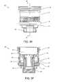
- FIG. 3Dis an exploded front view of a piston kit for use with the hydrogenerator flush valve in a urinal in accordance with the present invention
- FIG. 3Eis an assembled front plan view of the piston kit of FIG. 3D ;
- FIG. 3Fis a cross-sectional view of the piston kit of FIG. 3E taken along line 3 F- 3 F;
- FIG. 4Ais a cross-sectional view of the hydrogenerator flush valve of FIG. 1 when the piston kit is in a first position;
- FIG. 4Bis a cross-sectional view of the hydrogenerator flush valve of FIG. 1 when the piston kit is in a second position;
- FIGS. 5A-5Care a cross-sectional view, a top plan view, and a side view, respectively, of a rotor of a power generating device of the hydrogenerator flush valve in accordance with the present invention
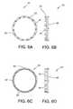
- FIGS. 6A and 6Bare a top plan view and a side view, respectively, of one embodiment of a stator of a power generating device of the hydrogenerator flush valve in accordance with the present invention
- FIGS. 6C and 6Dare a top plan view and a side view, respectively, of another embodiment of a stator of a power generating device of the hydrogenerator flush valve in accordance with the present invention.
- FIGS. 6E and 6Fare a top plan view and a side view, respectively, of still another embodiment of a stator of a power generating device of the hydrogenerator flush valve in accordance with the present invention.
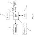
- FIG. 7is a block diagram illustrating a control system for use with the hydrogenerator flush valve in accordance with the present invention.
- FIGS. 8A-8Care flow diagrams illustrating the method performed by charging circuitry to charge a supercapacitor from the power generating device in accordance with the present invention
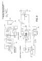
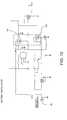
- FIGS. 9 and 10are circuit diagrams illustrating the circuitry required for performing the method of FIGS. 8A-8C ;
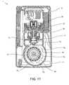
- FIG. 11is a cross-sectional view of the hydrogenerator flush valve of FIG. 1 .
- a hydrogenerator flush valvegenerally denoted as reference numeral 1
- housing 7has a split construction and is constituted of an upper valve cap 9 , which covers an upper portion of primary valve casing 3 , a front cover 11 which covers a lower portion of a front side of primary valve casing 3 and secondary valve casing 5 , and a rear cover 13 which covers a lower portion of a rear side of primary valve casing 3 and secondary valve casing 5 .
- Primary valve casing 3includes a cylindrical water inlet 15 that is communicably connected with a water supply pipe 17 and is formed in an approximately middle right side portion thereof.
- secondary valve casing 5includes a cylindrical water outlet 19 which is communicably connected, via a water outlet pipe 21 , with a toilet bowl (not shown). Cylindrical water outlet 19 is formed on a lower portion of secondary valve casing 5 .
- Hydrogenerator flush valve 1further includes an open/close valve 23 that is disposed within primary valve casing 3 on a downstream side of water inlet 15 .
- Open/close valve 23includes a solenoid valve 25 , a solenoid flange 27 , and a piston kit 29 .
- piston kit 29includes a piston body 31 .
- a brass insert 33 and sealing member 35are disposed within piston body 31 .
- the top of piston body 31is sealed with a cup seal 37 .
- a bottom portion of piston body 31is sealed with a piston base 39 and face seal 41 .
- a flow ring nut 43is coupled to the bottom of face seal 41 .
- a plurality of holes 45is disposed around the circumference of a bottom portion of piston body 31 . Desirably, six holes 45 are provided to allow water to flow inside piston kit 29 .
- An orifice hole 46is also provided in piston body 31 to allow the water entering through holes 45 to enter an upper chamber 47 of piston body 31 .
- Piston kit 29is configured to be used with hydrogenerator flush valve 1 when hydrogenerator flush valve 1 is installed in a water closet or toilet. Alternatively, hydrogenerator flush valve 1 may be installed in a urinal. When hydrogenerator flush valve 1 is installed in a urinal, a different piston kit 29 ′ is provided as illustrated in FIGS. 3D-3F . Piston kit 29 ′ is identical to piston kit 29 except for the design of flow ring nut 43 ′. Flow ring nut 43 ′, as can be seen in FIGS.
- 3D-3Fincludes a larger, upper brim 44 than flow ring nut 43 of piston kit 29 . This allows for a lesser flow rate for the hydrogenerator flush valve 1 when it is implemented in a urinal, thereby allowing the urinal to function properly.
- solenoid valve 25is in a closed, first position, as shown in FIG. 3D , and water is permitted to enter piston body 31 through holes 45 . The water proceeds to fill upper chamber 47 through orifice hole 46 . Thereafter, solenoid valve 25 is controlled by a control system, as will be described hereinafter, to move to an open, second position, as shown in FIG. 4B .
- solenoid valve 25is controlled to return to the closed, first position and water enters piston body 31 through holes 45 and fills upper chamber 47 through orifice hole 46 . This causes the pressure to rise in upper chamber 47 until piston kit 29 , 29 ′ has sealed to valve casing 3 with face seal 41 , thereby blocking the flow of water from water supply pipe 17 as shown in FIG. 4A .
- hydrogenerator flush valve 1has been described hereinabove as including a piston kit 29 , 29 ′ as shown in FIGS. 3A-3C or 3 D- 3 F, this is not to be construed as limiting the present invention as any suitable piston kit may be utilized.
- hydrogenerator flush valve 1further includes a power generating device disposed within primary valve casing 3 and secondary valve casing 5 .
- the power generating deviceincludes: a volute 51 formed in primary valve casing 3 and configured to receive water from water supply pipe 17 ; a stator 53 having a plurality of blades 55 positioned around a circumference thereof positioned within volute 51 ; a rotor 57 positioned within the stator 53 ; and a generator 59 coupled to rotor 57 .
- volute 51starts 30 degrees from a centerline of primary valve casing 3 and sweeps 300 degrees about the axis of stator 53 and rotor 57 .
- the diameter of volute 51 across this sweepreduces from about 13.5 mm to about 4.6 mm.
- rotor 57is provided as a Francis-type turbine.
- a Francis-type turbineis a type of water turbine that was developed by James B. Francis and has an inward flow reaction turbine that combines radial and axial flow concepts. More specifically, a Francis-type turbine is a reaction turbine, which means that the working fluid changes pressure as it moves through the turbine, giving up its energy. Francis-type turbines are typically used in large-scale hydroelectric producing plants, such as at the base of a dam.
- Volute 51 , stator 53 , and rotor 57are preferably embodied as a small-scale Francis-type turbine and include a plurality of guide blades 55 configured to direct the water tangentially to rotor 57 .
- Rotor blade 61 spacingmay vary between about 3.7 mm to about 6.3 mm apart and may be rotated 65 degrees counter-clockwise from a line tangent to a rotor body 63 .
- stator 53includes a circular, O-shaped body 65 having a plurality of blades 55 equally spaced around a circumference thereof.
- the stator 53 shown in FIGS. 6A and 6Bis optimized for use in a water closet flush valve.
- An alternative embodiment of stator 53 ′is illustrated in FIGS. 6C and 6D .
- Stator 53 ′also includes a circular, O-shaped body 65 ′ having a plurality of blades 55 ′ equally spaced around a circumference thereof.
- Stator 53 ′is optimized for use in a low flow rate urinal flush valve.
- Yet another alternative embodiment of stator 53 ′′is illustrated in FIGS. 6E and 6F .
- Stator 53 ′′also includes a circular, O-shaped body 65 ′′ having a plurality of blades 55 ′′ equally spaced around a circumference thereof. Stator 53 ′′ is optimized for use in a urinal flush valve.
- the spacing of blades 55 , 55 ′, and 55 ′′is set such that they are close enough to maximize the power obtained with the least amount of head loss.
- stator blades 55 ′may be spaced about 0.5 mm apart when provided in a low flow rate urinal flush valve (see FIGS. 6C and 6D ), about 3.0 mm apart when provided in a urinal flush valve (see FIGS. 6E and 6F ) or about 6.0 mm apart when provided in a water closet flush valve (see FIGS.
- stator blades 55 , 55 ′, or 55 ′′are rotated about 17 degrees clockwise from a line tangent to body 65 , 65 ′, or 65 ′′ of stator 53 , 53 ′, or 53 ′′.
- Rotor 57is positioned within an opening of body 65 , 65 ′, or 65 ′′ as shown in FIG. 11 .
- Generator 59may be embodied as a three-phase A.C., brushless motor having a drive shaft 67 .
- the three-phase A.C., brushless motormay be a USAutomation USB101-03 motor.
- Rotor 57is coupled to drive shaft 67 of the motor of generator 59 by a suitable fastening means, such as a screw 69 . The rotation of rotor 57 , therefore, would cause rotation of drive shaft 67 of the motor, thereby generating electricity.
- hydrogenerator flush valve 1further includes a main printed circuit board (PCB)/battery assembly 71 mounted within an upper portion of upper valve cap 9 .
- Main PCB/battery assembly 71houses a control system mounted on a main PCB 73 and a backup battery 75 .
- the control systemmay be embodied as a microcontroller or microprocessor.
- Battery 75is desirably a non-rechargeable lithium battery. However, this is not to be construed as limiting the present invention as any suitable battery may be utilized.
- Solenoid valve 25 , battery 75 , a sensor array 77 , a communication interface 79 , and generator 59are operationally coupled to the control system mounted on main PCB 73 . Further, a charging device, discussed in greater detail hereinafter, is provided in the control system. The charging device stores electric energy generated by generator 59 and supplies the stored electric energy to respective portions of hydrogenerator flush valve 1 , such as solenoid valve 25 and sensor array 77 .
- Sensor array 77includes a human body detection system that includes a first infrared emitter 81 , a second infrared emitter 83 , and a detector sensor 85 positioned in a vertical row, such that first infrared emitter 81 is at the top of the row, second infrared emitter 83 is at the bottom of the row, and detector sensor 85 is midway between first infrared emitter 81 and second infrared emitter 83 .
- First and second infrared emitters 81 , 83are further positioned in the vertical row such that the infrared beams produced by each cross at approximately 11 inches and at approximately 33 inches. This illuminates the area of interest and assists in preventing false positive detections as the beams cross twice before they reach the door of a stall where hydrogenerator flush valve 1 is positioned.
- Detector sensor 85is embodied as an integrated circuit that includes an infrared proximity detector and an ambient light detector.
- the ambient light detectormay be used in a power saving feature to put the control system to sleep when ambient light is below a certain threshold as will be discussed in greater detail hereinafter.
- An example of such a detector sensor 85is the TSL2771 light-to-digital converter manufactured by TAOS, Inc. of Plano, Tex.
- the combination of the infrared proximity detector and the ambient light detectorenables occupant detection based on a pattern of decreased/increased ambient light reflections followed by increasing infrared reflections and occupant absence by decreasing infrared reflections and increased/decreased ambient light.
- the ambient light patternvaries based on the position of the light source relative to the valve and the reflectivity of user. Occupant detection based on Pattern Recognition would eliminate the uncontrolled variable of infrared absorption rate of various clothing materials, which is a common problem for other proximity sensors based solely on infrared reflections.
- Detector sensor 85is precisely positioned behind a focusing lens 86 which focuses the reflected infrared light from first and second infrared emitters 81 and 83 and ambient light from the surroundings.
- the lens 86reduces the power requirements needed for first and second infrared emitters 81 and 83 by focusing the infrared (IR) reflections from a larger surface area directly onto the sensor. The level of reflections seen is increased so the amount of IR emitted can be reduced while maintaining the same level of received reflections, thereby reducing the power consumption of the system.
- Sensor array 77may further include a plurality of status light emitting diodes (LEDs) 89 provided in the vertical row with first infrared emitter 81 , second infrared emitter 83 , and detector sensor 85 to provide information to a user regarding the status of hydrogenerator flush valve 1 .
- LEDsstatus light emitting diodes
- FIG. 1two status LEDs 89 may be positioned above detector sensor 85 .
- One of these status LEDs 89is blue and the other is green.
- two status LEDs 89may be positioned below detector sensor 85 .
- One of these status LEDs 89is blue and the other is green. Accordingly, various information can be provided to the user based on which status LEDs 89 are lit.
- a microcontrollercan use input from the power generating device to determine if solenoid valve 25 is operating properly. More specifically, when solenoid valve 25 is activated, the power generated by the power generating device is analyzed by the microcontroller, in addition to the load switch in the event that the supercapacitor is fully charged, to determine whether solenoid valve 25 is opening and closing properly. For instance, if the power generating device continues to generate power even when the microcontroller has sent a signal to close the solenoid valve 25 , this could mean that the solenoid valve 25 is malfunctioning and has remained open. Accordingly, the microcontroller will send a signal to have one or more of status LEDs 89 to turn on to alert a user that solenoid valve 25 is malfunctioning. The microcontroller will also attempt to close solenoid valve 25 several times after the failure is noted. The same procedure is followed if solenoid valve 25 fails to open properly.
- poweris generated by generator 59 of the power generating device as described hereinabove at block 700 .
- the output of generator 59is rectified by a six-diode rectifier 91 provided in series therewith at block 701 .
- a load switch 93is provided between rectifier 91 and a main supercapacitor 95 .
- Main supercapacitor 95may be a 0.47 F capacitor capable of charging up to 11VDC.
- Load switch 93is automatic and is controlled by a set threshold voltage to protect overcharging of main supercapacitor 95 and the state of load switch 93 is monitored by the microcontroller at block 702 . If the charge on main supercapacitor 95 is below 11VDC, load switch 93 remains open and main supercapacitor 95 continues to store the electrical energy produced by generator 59 . If, at block 703 , the load switch threshold level is met and the charge on main supercapacitor 95 has reached 11VDC, load switch 93 is enabled and monitored by the microcontroller, thereby preventing any additional electrical energy generated by generator 59 from charging main supercapacitor 95 . Once the charge on main supercapacitor 95 falls below 11VDC, load switch 93 returns to the disabled position, thereby allowing main supercapacitor 95 to again be charged by the electrical energy produced by generator 59 .
- the microcontrollerdetermines whether a buck converter 97 or boost converter 99 should be enabled based on the voltage of main supercapacitor 95 to either charge a secondary supercapacitor 101 capable of charging up to 3.3VDC or boost main supercapacitor 95 directly to a comparator circuit. If the charge on main supercapacitor 95 is greater than 3.3VDC, the buck converter 97 is enabled at block 705 . The buck converter 97 charges secondary supercapacitor 101 to 3.3VDC at block 706 .
- a load switchis enabled to disable secondary supercapacitor 101 from the circuit when main supercapacitor 95 has a voltage that is below 3.3VDC and boosted to provide power to solenoid valve 25 and/or sensor array 77 . This voltage is then fed into a comparator circuit at block 800 as will be described in greater detail hereinafter.
- boost converter 99is enabled by a load switch 103 when the voltage on main supercapacitor 95 drops to between 1.5VDC and 3VDC. Load switch 103 is enabled/disabled by the microcontroller. Boost converter 99 increases the voltage from main supercapacitor 95 to 3.3VDC when load switch 103 is enabled. This voltage is then fed into a comparator circuit at block 800 as will be described in greater detail hereinafter.
- the main supercapacitor power from either secondary supercapacitor voltage or boost converter voltageis fed to a comparator that works in conjunction with a first p-channel MOSFET 107 and a second p-channel MOSFET 109 at block 801 to automatically switch between the main supercapacitor power and backup battery 75 power (see block 803 ) based on a set threshold voltage and is monitored by the microcontroller provided at block 802 .
- This automatic switchingoccurs when main supercapacitor 95 has a voltage below 3VDC.
- the output of the comparatoris a 3V main power source provided from main supercapacitor 95 if sufficiently charged by generator 59 or from backup battery 75 (see block 803 ).
- the 3V main power sourceis provided to a 3V linear regulator at block 900 .
- the 3V linear regulatormaintains 3.0V for the microcontroller and sensor over the 3V main power source voltage range of about 3.0V to 3.6V.
- the output of the 3V linear regulatoris then provided to the microcontroller on main PCB 73 which controls solenoid valve 25 , sensor array 77 , and communication interface 79 .
- Communication interface 79may be an RS232 interface and is used to allow the microcontroller to communicate with a personal computer (PC) or a custom mobile device for production tests and field adjustments made by the customer in the field.
- Hydrogenerator flush valve 1may be physically connected, via communication interface 79 , to the PC or mobile device via TTL-232R-3V3-AJ USB-to-TTL Level Serial Cable.
- the communication interface 79may be a wireless interface.
- the microcontroller of hydrogenerator flush valve 1provides various power saving features. Previous automatic flush valves have been controlled to have the sensors send an infrared beam once per second, 24 hours per day, every day of the year that it is in service. However, since hydrogenerator flush valve 1 is configured to run off of power generated by generator 59 , the following sensor detection control algorithm will be used to save power and still detect a user. First, detector sensor 85 looks for changes in the ambient light level at a default sampling rate of 2 seconds. If the ambient light level changes by more than 5% between two consecutive readings, this indicates a user may be present. The first and second infrared emitters 81 and 83 are then turned on to confirm the presence of a user and subsequently used to detect the absence of the user.
- the microcontroller of hydrogenerator flush valve 1can also be programmed to include a dual flush water saving feature as follows: 1) if detector sensor 85 detects that a person is present for less than 60 seconds, the microcontroller will control hydrogenerator flush valve 1 to provide a short flush (1.1 gpf/4.2 Lpf); and 2) if detector sensor 85 detects that a person is present for more than 60 seconds, the microcontroller will control hydrogenerator flush valve 1 to provide a normal flush (1.6 gpf/6.0 Lpf).
- the ambient light sensor of detector sensor 85is a critical part of the power saving features. There are two phases in which the detector sensor 85 operates: 1) during a seven day Environmental Trending data collection period; and 2) after the Environmental Trending is complete and a trend has been successfully established. Both phases utilize power saving measures.
- the default ambient light sampling rateis 2 seconds. If the detector sensor 85 has not sensed a person within the last 2 hours, the ambient light sampling rate is reduced to 3 seconds. If detector sensor 85 has not sensed a person within the last 4 hours, the ambient light sampling rate is reduced to 4 seconds. After a trend is successfully established following the seven day data collection period, in hours of activity the default ambient light sampling rate is 2 seconds.
- the sampling rateis reduced to 10 seconds or “sleep” mode.
- the control system of the valvethereafter looks ahead to the next hour in the trend. If the next hour has no activity and low light, the sampling rate remains at 10 seconds. If the next hour has activity or an increase in ambient light, the sampling rate is increased to 2 seconds. “Sleep” is the flush valve mode in which the control system of hydrogenerator flush valve 1 only checks the ambient light level every 10 seconds.
- the microcontrollercontinually monitors ambient light and traffic patterns to maximize the power savings based on the installation environment, or environmental trending.
- the ambient light levelwill be recorded.
- the ambient light levelwill be recorded over a period of one hour.
- the number of activations that occur during that one hourwill also be recorded.
- the average ambient light level and number of activationswill be recorded to develop a trend.
- This trendwill provide two features: 1) will associate a light level with activity to provide a baseline light level for comparison to when the environment is determined to be “dark” since each install light level is unique; and 2) will allow the unit to go to sleep faster based on data from the trend.
- the ambient light sensorcan sample less often than the time between 5:00 am-6:00 am where activity level, based on trending data, increases. This allows the flush valve to distinguish between night time or an install location that simply has a light sensor that turns the light on or off based on the occupant entering or leaving the bathroom. A change in activity level will result in a new environment adjustment sequence for a period of seven days. Before or between an environmental adjustment sequence is complete, the valve sampling rate will be based on activity level.
- hydrogenerator flush valve 1includes a manually operated valve 111 that allows a user to manually flush the toilet and override the automatic flushing features of hydrogenerator flush valve 1 .
- solenoid valve 25is controlled by the microcontroller on main PCB 73 to move to an open, second position based on feedback from sensor array 77 .
- Thisallows the water in upper chamber 47 to evacuate through passage 49 in solenoid flange 27 , thereby causing piston kit 29 to move upward and allow water from water supply pipe 17 to flow in a direction of arrows A 1 (see FIG. 3E ).
- Primary valve casing 3is configured such that water received from water supply pipe 17 takes an approximately 90° turn within primary valve casing 3 and substantially all of the water is directed to volute 51 .
- Volute 51directs substantially all of the water received from water supply pipe 17 in a circumferential direction as indicated by arrows A 2 through the plurality of blades 55 of stator 53 , as indicated by arrows A 3 , to rotor 57 , thereby causing rotor 57 to rotate (see FIG. 10 ). Since rotor 57 is coupled to generator 59 , this rotation causes generator 59 to generate electricity as discussed in greater detail hereinabove. The water then makes another 90° turn within secondary valve casing 5 and escapes from water outlet pipe 21 , as shown by arrow A 4 , to evacuate the toilet bowl.
- solenoid valve 25is controlled by the microcontroller to return to the closed, first position and water fills upper chamber 47 through orifice hole 46 . This causes the pressure to rise in upper chamber 47 until piston kit 29 has sealed to primary valve casing 3 with face seal 41 , thereby blocking the flow of water from water supply pipe 17 .
- the power generating device of the present inventionhas been described hereinabove for use with a flush valve for a water closet-type flushing device, this is not to be construed as limiting the present invention as the power generating device may be utilized in any suitable plumbing fixture such as, but not limited to, a urinal flush valve, a faucet, and a showerhead.
Landscapes
- Engineering & Computer Science (AREA)
- Power Engineering (AREA)
- Chemical & Material Sciences (AREA)
- Combustion & Propulsion (AREA)
- Mechanical Engineering (AREA)
- General Engineering & Computer Science (AREA)
- Sanitary Device For Flush Toilet (AREA)
- Other Liquid Machine Or Engine Such As Wave Power Use (AREA)
Abstract
Description
| TABLE 1 | ||
| Condition | LED Color | Cycle |
| Low Battery/ | Green (Top)/Blue | Flash once every X seconds during “normal” |
| Battery Issue | (Top) | operation |
| Solenoid Issue | Blue (Bottom)/Green | Flash once every X seconds during “normal” |
| (Bottom) | operation | |
| Generator Issue | Green (Top)/Blue | Flash once every X seconds during “normal” |
| (Bottom) | operation | |
| Sensor Issue | Blue (Bottom)/Green | Flash once every X seconds during “normal” |
| (Bottom)/Green (Top) | operation | |
| User Detection | Blue (Top) | Flash with each sensor pulse during user |
| confirmation | ||
| User Absence | Green (Top) | Only occurs after user confirmation has been |
| detected | ||
| Good Cycle/ | All 4 LEDs top to | Light blue bottom if charge <=2.75 V |
| Supercapacitor | bottom for 0.5S | Light blue bottom and green bottom if >2.75 V |
| Charge Level Status | & <=5.5 V | |
| operation (occurs at | Light blue bottom, green bottom, green top if | |
| flush) | >5.5 V & <=8.25 V | |
| Light all 4 if >8.25 V | ||
| Going to sleep/low | Blue (Bottom)/Blue | Single cycle for 2S |
| light detected for X | (Top) | |
| time | ||
| Low light detected | All 4 | Single cycle for 0.25S |
| Bright light detected | All 4 | Single cycle for 0.25S |
Claims (15)
Priority Applications (2)
| Application Number | Priority Date | Filing Date | Title |
|---|---|---|---|
| US12/887,756US8698333B2 (en) | 2009-09-23 | 2010-09-22 | Flush valve hydrogenerator |
| CA2715505ACA2715505C (en) | 2009-09-23 | 2010-09-23 | Flush valve hydrogenerator |
Applications Claiming Priority (2)
| Application Number | Priority Date | Filing Date | Title |
|---|---|---|---|
| US24497009P | 2009-09-23 | 2009-09-23 | |
| US12/887,756US8698333B2 (en) | 2009-09-23 | 2010-09-22 | Flush valve hydrogenerator |
Publications (2)
| Publication Number | Publication Date |
|---|---|
| US20110071698A1 US20110071698A1 (en) | 2011-03-24 |
| US8698333B2true US8698333B2 (en) | 2014-04-15 |
Family
ID=43757344
Family Applications (1)
| Application Number | Title | Priority Date | Filing Date |
|---|---|---|---|
| US12/887,756Active2031-12-22US8698333B2 (en) | 2009-09-23 | 2010-09-22 | Flush valve hydrogenerator |
Country Status (2)
| Country | Link |
|---|---|
| US (1) | US8698333B2 (en) |
| CA (1) | CA2715505C (en) |
Cited By (17)
| Publication number | Priority date | Publication date | Assignee | Title |
|---|---|---|---|---|
| US20130167953A1 (en)* | 2010-03-30 | 2013-07-04 | Toto Ltd. | Faucet device |
| US9441885B2 (en) | 2011-04-18 | 2016-09-13 | Bradley Fixtures Corporation | Lavatory with dual plenum hand dryer |
| US9464423B2 (en) | 2013-02-21 | 2016-10-11 | Shanghai Kohler Electronics, Ltd. | Emergency flush apparatus and method |
| US9756992B2 (en) | 2013-03-15 | 2017-09-12 | Vsi Import Solutions, Llc | Electronic residential tissue dispenser |
| US9907441B2 (en) | 2014-04-18 | 2018-03-06 | Vsi Import Solutions, Llc | Electronic residential tissue dispenser |
| US10041236B2 (en) | 2016-06-08 | 2018-08-07 | Bradley Corporation | Multi-function fixture for a lavatory system |
| US10072668B2 (en) | 2016-08-11 | 2018-09-11 | Zhora Hovsep MALOYAN | Systems and methods for generating clean energy through hydrodynamic closed cycle |
| US10100501B2 (en) | 2012-08-24 | 2018-10-16 | Bradley Fixtures Corporation | Multi-purpose hand washing station |
| US20190219276A1 (en)* | 2018-01-15 | 2019-07-18 | Advanced Conservation Technologies Distribution, Inc. | Fluid Distribution System |
| USD861128S1 (en)* | 2018-03-27 | 2019-09-24 | Fujian Ospring Science Technology Development Co., Ltd. | Water purifier |
| US10570913B2 (en) | 2016-08-11 | 2020-02-25 | Zhora Hovsep MALOYAN | Systems and methods for generating clean energy through hydrodynamic closed cycle |
| US20200256309A1 (en)* | 2019-02-10 | 2020-08-13 | Stephen Tomás Strocchia-Rivera | Deep Water Pressure Electricity Generating Method, Apparatus and System |
| US10934992B2 (en)* | 2019-02-18 | 2021-03-02 | Toto Ltd. | Hydraulic generator, spouting apparatus, and method for manufacturing hydraulic generator |
| US11859375B2 (en) | 2009-12-16 | 2024-01-02 | Kohler Co. | Touchless faucet assembly and method of operation |
| US11984768B2 (en) | 2020-04-17 | 2024-05-14 | Zurn Water, Llc | Hydroelectric generator for faucet and flush valve |
| US11990823B2 (en) | 2021-05-14 | 2024-05-21 | Rain Bird Corporation | Self-powered irrigation systems, generator systems and methods of controlling irrigation |
| US12283816B2 (en) | 2023-01-09 | 2025-04-22 | Rain Bird Corporation | Hydro-power generation for irrigation control |
Families Citing this family (14)
| Publication number | Priority date | Publication date | Assignee | Title |
|---|---|---|---|---|
| MX346610B (en) | 2011-03-15 | 2017-03-27 | Sloan Valve Co | Automatic faucets. |
| US9695579B2 (en)* | 2011-03-15 | 2017-07-04 | Sloan Valve Company | Automatic faucets |
| US20140312253A1 (en)* | 2011-12-05 | 2014-10-23 | Livne Gan | Compact self powered and automated attachment to a fluid system |
| US9554958B2 (en)* | 2013-12-11 | 2017-01-31 | General Electric Company | System and method for detection of infant presence |
| US9592034B2 (en)* | 2014-03-05 | 2017-03-14 | Newvistas, Llc | Urine specimen capture and analysis device |
| US10060775B2 (en) | 2014-03-10 | 2018-08-28 | Driblet Labs, LLC | Smart water management system |
| US10932103B1 (en)* | 2014-03-21 | 2021-02-23 | Amazon Technologies, Inc. | Determining position of a user relative to a tote |
| CN104390727B (en)* | 2014-11-25 | 2017-07-04 | 南车株洲电机有限公司 | A kind of rotor temperature measurement on-line probe |
| CN106552723B (en)* | 2015-09-30 | 2019-12-27 | 黄俊铭 | Intelligent shower nozzle device |
| US9943869B2 (en)* | 2016-03-03 | 2018-04-17 | National Applied Research Laboratories | Self-powered showerhead |
| EP3228861B1 (en)* | 2016-03-29 | 2020-02-19 | PHD, Inc. | Actuator exhaust fluid energy harvester |
| CN108418291B (en)* | 2018-03-27 | 2024-05-14 | 青海能高新能源有限公司微电网储能技术分公司 | Pipeline type self-generating miniature energy storage power supply |
| CO2020013072A1 (en)* | 2020-10-20 | 2020-10-30 | Compania Colombiana De Ceram S A S | Flushometer type discharge system with improved properties and measurement of variables, and sanitary that includes the same |
| CN215843658U (en)* | 2021-07-02 | 2022-02-18 | 厦门市得尔美卫浴有限公司 | Luminous water outlet device, pull-type luminous faucet and luminous spring faucet |
Citations (92)
| Publication number | Priority date | Publication date | Assignee | Title |
|---|---|---|---|---|
| US1402771A (en) | 1922-01-10 | johns | ||
| US3233165A (en) | 1963-05-10 | 1966-02-01 | Gen Electric | Voltage regulator with rectifier and phase controlled scr inverter |
| US3575640A (en) | 1967-11-27 | 1971-04-20 | Omron Tateisi Electronics Co | Automatic water supply system |
| US3761795A (en) | 1972-01-13 | 1973-09-25 | Legg Ltd | Battery charging apparatus |
| US3867682A (en) | 1972-11-20 | 1975-02-18 | Sony Corp | Battery charger with means for preventing overcharging of the battery |
| US3917017A (en) | 1974-01-25 | 1975-11-04 | West Virginia High Bird Corp E | Battery operated vehicle drive |
| US4122381A (en) | 1977-03-04 | 1978-10-24 | Zeynab Edda Sturm | Home power station |
| US4321523A (en) | 1978-10-05 | 1982-03-23 | The Gates Rubber Company | Battery charger and power supply circuitry |
| US4485310A (en) | 1981-04-30 | 1984-11-27 | Valbrev (Societe A Respondabilite Limitee) | Combination of a compression or expansion turbine engine and an electric motor |
| US4520516A (en) | 1983-09-23 | 1985-06-04 | Parsons Natan E | Ultrasonic flow-control system |
| US4524285A (en) | 1979-09-14 | 1985-06-18 | Rauch Hans G | Hydro-current energy converter |
| US4555637A (en) | 1982-07-26 | 1985-11-26 | Acd, Inc. | High speed turbogenerator for power recovery from fluid flow within conduit |
| US4564889A (en) | 1982-11-10 | 1986-01-14 | Bolson Frank J | Hydro-light |
| US4604735A (en) | 1983-09-23 | 1986-08-05 | Recurrent Solutions, Inc. | Ultrasonic motion detection system |
| US4616298A (en) | 1985-12-26 | 1986-10-07 | Bolson Frank J | Water-powered light |
| US4629904A (en) | 1984-03-21 | 1986-12-16 | Rojo Jr Agustin | Micro-hydroelectric power plant |
| US4731545A (en) | 1986-03-14 | 1988-03-15 | Desai & Lerner | Portable self-contained power conversion unit |
| US4839039A (en) | 1986-02-28 | 1989-06-13 | Recurrent Solutions Limited Partnership | Automatic flow-control device |
| US4886207A (en) | 1988-09-14 | 1989-12-12 | Lee Chang H | Automatic mixing faucet |
| US4920465A (en) | 1988-11-15 | 1990-04-24 | Alopex Industries, Inc. | Floating fountain device |
| US4936508A (en) | 1989-05-02 | 1990-06-26 | Ingalz Thomas J | Shower head volume meter with alarm signal |
| US4963780A (en) | 1988-09-27 | 1990-10-16 | Kwc Ag | Water driven generator for sanitary domestic installation |
| US4969797A (en) | 1989-03-22 | 1990-11-13 | Matsushita Electric Industrial Co., Ltd. | Fan motor |
| US5089763A (en) | 1988-12-12 | 1992-02-18 | Siemens Aktiengesellschaft | Battery charging unit for a medical appliance |
| US5224685A (en) | 1992-10-27 | 1993-07-06 | Sing Chiang | Power-saving controller for toilet flushing |
| US5225689A (en) | 1990-12-15 | 1993-07-06 | Leuze Electronic Gmbh & Co. | Reflected light sensor having dual emitters and receivers |
| US5349985A (en) | 1991-07-20 | 1994-09-27 | Cosmos Entwicklungs-Und Forschungsanstalt | Plumbing fixture |
| US5559379A (en) | 1993-02-03 | 1996-09-24 | Nartron Corporation | Induction air driven alternator and method for converting intake air into current |
| US5629606A (en) | 1994-12-28 | 1997-05-13 | Nippondenso Co., Ltd. | Battery charging device for vehicle |
| US5699833A (en) | 1996-03-25 | 1997-12-23 | Tsataros; Eddie J. | Electro-mechanical fluid flow control apparatus |
| US5769177A (en) | 1990-11-24 | 1998-06-23 | Wickman; Dominic | Hydro electric vehicle drive system |
| US5915417A (en) | 1997-09-15 | 1999-06-29 | T&S Brass And Bronze Works, Inc. | Automatic fluid flow control apparatus |
| US5950983A (en) | 1993-08-23 | 1999-09-14 | Sloan Valve Company | Infrared detector with beam path adjustment |
| US6036333A (en) | 1999-05-04 | 2000-03-14 | Spiller; Andrew | Water faucet generated emergency lighting system |
| US6061843A (en) | 1994-03-30 | 2000-05-16 | Keramag Keramische Werke Ag | Method for automatically triggering a flushing event |
| US6158541A (en) | 1997-02-14 | 2000-12-12 | Toyota Jidosha Kabushiki Kaisha | Electric motor vehicle having means for fully discharging part of energy storage device when energy amount in the other part is larger than a threshold |
| US6195588B1 (en) | 1997-12-31 | 2001-02-27 | Sloan Valve Company | Control board for controlling and monitoring usage of water |
| US6219857B1 (en) | 1999-12-16 | 2001-04-24 | Hydrotek Corporation | Sensor device for use with a flush valve |
| JP2001124058A (en) | 1999-10-21 | 2001-05-08 | Canon Precision Inc | Heat dissipation dynamic pressure fluid bearing brushless motor |
| US6250601B1 (en) | 1997-07-18 | 2001-06-26 | Kohler Company | Advanced touchless plumbing systems |
| US20020041100A1 (en) | 2000-09-06 | 2002-04-11 | Kabushiki Kaisha Sankyo Seiki Seisakusho | Small-sized hydroelectric power generating apparatus |
| US20020047374A1 (en) | 2000-09-06 | 2002-04-25 | Kabushiki Kaisha Sankyo Seiki Seisakusho | Small-sized hydroelectric power generating apparatus |
| US20020113442A1 (en) | 2001-02-09 | 2002-08-22 | Yukinobu Yumita | Small hydroelectric power generator |
| US20020121617A1 (en) | 2001-03-02 | 2002-09-05 | Hu Chung Li | Power supply unit for a hydraulic system |
| US6481634B1 (en) | 1996-04-04 | 2002-11-19 | Smart Wave Technologies Inc. | Fluid data monitoring and control system |
| US6499152B2 (en) | 2001-01-18 | 2002-12-31 | Geberit Technik Ag | Flush controller |
| US20030041370A1 (en) | 2001-09-05 | 2003-03-06 | Yu-Lin Chung | Wireless auto flusher |
| JP2003105818A (en) | 2001-09-27 | 2003-04-09 | Toto Ltd | Automatic faucet |
| US6560790B2 (en) | 2001-03-06 | 2003-05-13 | Geberit Technik Ag | Flush control |
| US20030164612A1 (en) | 2000-05-17 | 2003-09-04 | Yukinobu Yumita | Small power generating device and water faucet device |
| US6639328B2 (en) | 2000-12-19 | 2003-10-28 | Capstone Turbine Corporation | Microturbine/capacitor power distribution system |
| US6671893B1 (en) | 2002-12-17 | 2004-01-06 | Nicole Family Trust | Toilet and urinal leak, overflow and stuck valve prevention system |
| US20040041110A1 (en) | 2000-11-14 | 2004-03-04 | Yoshiyuki Kaneko | Faucet controller |
| JP2004257143A (en) | 2003-02-26 | 2004-09-16 | Inax Corp | Semi-automatic faucet |
| US6798080B1 (en) | 1999-10-05 | 2004-09-28 | Access Business Group International | Hydro-power generation for a water treatment system and method of supplying electricity using a flow of liquid |
| US20040195840A1 (en) | 1999-10-05 | 2004-10-07 | Baarman David W. | Miniature hydro-power generation system |
| US20050006903A1 (en) | 2003-05-19 | 2005-01-13 | Yukinobu Yumita | Hydraulic power generating device |
| US6864591B2 (en) | 2003-05-20 | 2005-03-08 | Defrank Michael | Sprinkler activated generator |
| US6877170B1 (en) | 2003-07-21 | 2005-04-12 | Niccole Family Trust | Toilet control system |
| US20050098485A1 (en) | 2003-10-01 | 2005-05-12 | Water Pik, Inc. | End-of-faucet filter |
| US6894270B2 (en) | 2002-11-01 | 2005-05-17 | Delta Faucet Canada | Sensor for washroom device with a non-circular sensing zone |
| US6913203B2 (en) | 2003-12-03 | 2005-07-05 | Delangis Eric | Self powered electronically controlled mixing valve |
| US20060006354A1 (en) | 2002-12-04 | 2006-01-12 | Fatih Guler | Optical sensors and algorithms for controlling automatic bathroom flushers and faucets |
| US7112892B2 (en) | 2004-07-21 | 2006-09-26 | Avago Technologies General Ip (Singapore) Pte. Ltd. | Power source for sensors |
| US20070034258A1 (en) | 2001-07-27 | 2007-02-15 | Parsons Natan E | System and method for converting manually operated flush valves |
| US20070037470A1 (en) | 2005-08-09 | 2007-02-15 | Russell Rothan | Water-powered lighted toys |
| US20070057215A1 (en) | 2001-11-20 | 2007-03-15 | Parsons Natan E | Passive sensors and control algorithms for faucets and bathroom flushers |
| US7213782B2 (en) | 2004-01-30 | 2007-05-08 | Charles Agnew Osborne | Intelligent dispensing system |
| US20070102046A1 (en) | 2003-11-18 | 2007-05-10 | Motoyasu Kimura | Flow control device |
| US7253536B2 (en) | 2003-03-28 | 2007-08-07 | Toto Ltd. | Water supply apparatus |
| US20070246941A1 (en) | 2006-03-27 | 2007-10-25 | Shogo Tanaka | Hydraulic power generating device and manufacturing method therefor |
| US20070257803A1 (en) | 2006-05-03 | 2007-11-08 | Duke University & Duke University Health Systems | Rf controlled devices to increase compliance with handwashing protocols |
| US20070284552A1 (en) | 2006-04-06 | 2007-12-13 | Obalit Khorshid | Fluid control system, device and method |
| US20080010734A1 (en) | 2006-07-14 | 2008-01-17 | Frank Chang | Sensor-type flushing system for a toilet tank |
| US20080078014A1 (en) | 2006-09-29 | 2008-04-03 | Sloan Valve Company | Automatic dual flush activation |
| US20080087856A1 (en) | 2006-10-13 | 2008-04-17 | Sloan Valve Company | Programmable Automatic Flushometer |
| US7382061B2 (en) | 2002-09-30 | 2008-06-03 | Giuseppe Ferraro | Supercharger coupled to a motor/generator unit |
| US20080136191A1 (en) | 2003-10-09 | 2008-06-12 | Baarman David W | Miniature hydro-power generation system |
| US20080136190A1 (en) | 2004-10-19 | 2008-06-12 | Yong Bok Lee | Micro Power Generating Device |
| US7396000B2 (en) | 2001-12-04 | 2008-07-08 | Arichell Technologies Inc | Passive sensors for automatic faucets and bathroom flushers |
| US20080217923A1 (en) | 2007-03-06 | 2008-09-11 | Jen-Yen Yen | Hydraulic powered electric generator device |
| US20080231056A1 (en) | 2007-03-20 | 2008-09-25 | Chang Ting Wen | Hydroelectric generator turbine flow guide structure |
| US20080231051A1 (en) | 2003-03-06 | 2008-09-25 | Akira Toriyama | Midget gas turbine |
| US20080246282A1 (en) | 2007-04-09 | 2008-10-09 | Philip John Hathaway | System and method for generating residential hydropower |
| US20080284175A1 (en) | 2005-09-30 | 2008-11-20 | Hydro-Industries Tynat Ltd. | Self-Powered Non-Contact Water Appliance |
| US7468564B2 (en) | 2007-01-29 | 2008-12-23 | Wabtec Holding Corp. | Air turbine generator |
| US20090000023A1 (en) | 2007-06-27 | 2009-01-01 | Wegelin Jackson W | Fluid dispenser having infrared user sensor |
| US20090008943A1 (en) | 2007-07-05 | 2009-01-08 | John Joseph Kemper | Residential hydroelectric generator |
| US20090026768A1 (en) | 2007-07-23 | 2009-01-29 | Toto Ltd. | Faucet generator |
| US20090026769A1 (en) | 2007-07-23 | 2009-01-29 | Toto Ltd. | Faucet generator |
| US20090049599A1 (en) | 2002-12-04 | 2009-02-26 | Parsons Natan E | Passive sensors for automatic faucets and bathroom flushers |
| US20090077736A1 (en) | 2007-09-20 | 2009-03-26 | Bradley Fixtures Corporation | Lavatory System |
- 2010
- 2010-09-22USUS12/887,756patent/US8698333B2/enactiveActive
- 2010-09-23CACA2715505Apatent/CA2715505C/enactiveActive
Patent Citations (124)
| Publication number | Priority date | Publication date | Assignee | Title |
|---|---|---|---|---|
| US1402771A (en) | 1922-01-10 | johns | ||
| US3233165A (en) | 1963-05-10 | 1966-02-01 | Gen Electric | Voltage regulator with rectifier and phase controlled scr inverter |
| US3575640A (en) | 1967-11-27 | 1971-04-20 | Omron Tateisi Electronics Co | Automatic water supply system |
| US3761795A (en) | 1972-01-13 | 1973-09-25 | Legg Ltd | Battery charging apparatus |
| US3867682A (en) | 1972-11-20 | 1975-02-18 | Sony Corp | Battery charger with means for preventing overcharging of the battery |
| US3917017A (en) | 1974-01-25 | 1975-11-04 | West Virginia High Bird Corp E | Battery operated vehicle drive |
| US4122381A (en) | 1977-03-04 | 1978-10-24 | Zeynab Edda Sturm | Home power station |
| US4321523A (en) | 1978-10-05 | 1982-03-23 | The Gates Rubber Company | Battery charger and power supply circuitry |
| US4524285A (en) | 1979-09-14 | 1985-06-18 | Rauch Hans G | Hydro-current energy converter |
| US4485310A (en) | 1981-04-30 | 1984-11-27 | Valbrev (Societe A Respondabilite Limitee) | Combination of a compression or expansion turbine engine and an electric motor |
| US4555637A (en) | 1982-07-26 | 1985-11-26 | Acd, Inc. | High speed turbogenerator for power recovery from fluid flow within conduit |
| US4564889A (en) | 1982-11-10 | 1986-01-14 | Bolson Frank J | Hydro-light |
| US4520516A (en) | 1983-09-23 | 1985-06-04 | Parsons Natan E | Ultrasonic flow-control system |
| US4604735A (en) | 1983-09-23 | 1986-08-05 | Recurrent Solutions, Inc. | Ultrasonic motion detection system |
| US4629904A (en) | 1984-03-21 | 1986-12-16 | Rojo Jr Agustin | Micro-hydroelectric power plant |
| US4616298A (en) | 1985-12-26 | 1986-10-07 | Bolson Frank J | Water-powered light |
| US4839039A (en) | 1986-02-28 | 1989-06-13 | Recurrent Solutions Limited Partnership | Automatic flow-control device |
| US4839039B1 (en) | 1986-02-28 | 1994-02-22 | Recurrent Solutions Limited Partnership | |
| US4839039B2 (en) | 1986-02-28 | 1998-12-29 | Recurrent Solutions Ltd | Automatic flow-control device |
| US4731545A (en) | 1986-03-14 | 1988-03-15 | Desai & Lerner | Portable self-contained power conversion unit |
| US4886207A (en) | 1988-09-14 | 1989-12-12 | Lee Chang H | Automatic mixing faucet |
| US4963780A (en) | 1988-09-27 | 1990-10-16 | Kwc Ag | Water driven generator for sanitary domestic installation |
| US4920465A (en) | 1988-11-15 | 1990-04-24 | Alopex Industries, Inc. | Floating fountain device |
| US5089763A (en) | 1988-12-12 | 1992-02-18 | Siemens Aktiengesellschaft | Battery charging unit for a medical appliance |
| US4969797A (en) | 1989-03-22 | 1990-11-13 | Matsushita Electric Industrial Co., Ltd. | Fan motor |
| US4936508A (en) | 1989-05-02 | 1990-06-26 | Ingalz Thomas J | Shower head volume meter with alarm signal |
| US5769177A (en) | 1990-11-24 | 1998-06-23 | Wickman; Dominic | Hydro electric vehicle drive system |
| US5225689A (en) | 1990-12-15 | 1993-07-06 | Leuze Electronic Gmbh & Co. | Reflected light sensor having dual emitters and receivers |
| US5349985A (en) | 1991-07-20 | 1994-09-27 | Cosmos Entwicklungs-Und Forschungsanstalt | Plumbing fixture |
| US5224685A (en) | 1992-10-27 | 1993-07-06 | Sing Chiang | Power-saving controller for toilet flushing |
| US5559379A (en) | 1993-02-03 | 1996-09-24 | Nartron Corporation | Induction air driven alternator and method for converting intake air into current |
| US6161814A (en) | 1993-08-23 | 2000-12-19 | Sloan Valve Company | Infrared detector with beam path adjustment |
| US5950983A (en) | 1993-08-23 | 1999-09-14 | Sloan Valve Company | Infrared detector with beam path adjustment |
| US6061843A (en) | 1994-03-30 | 2000-05-16 | Keramag Keramische Werke Ag | Method for automatically triggering a flushing event |
| US5629606A (en) | 1994-12-28 | 1997-05-13 | Nippondenso Co., Ltd. | Battery charging device for vehicle |
| US5699833A (en) | 1996-03-25 | 1997-12-23 | Tsataros; Eddie J. | Electro-mechanical fluid flow control apparatus |
| US6481634B1 (en) | 1996-04-04 | 2002-11-19 | Smart Wave Technologies Inc. | Fluid data monitoring and control system |
| US6158541A (en) | 1997-02-14 | 2000-12-12 | Toyota Jidosha Kabushiki Kaisha | Electric motor vehicle having means for fully discharging part of energy storage device when energy amount in the other part is larger than a threshold |
| US6250601B1 (en) | 1997-07-18 | 2001-06-26 | Kohler Company | Advanced touchless plumbing systems |
| US5915417A (en) | 1997-09-15 | 1999-06-29 | T&S Brass And Bronze Works, Inc. | Automatic fluid flow control apparatus |
| US6195588B1 (en) | 1997-12-31 | 2001-02-27 | Sloan Valve Company | Control board for controlling and monitoring usage of water |
| US6701194B2 (en) | 1997-12-31 | 2004-03-02 | Sloan Valve Company | Control board for controlling and monitoring usage of water |
| US6036333A (en) | 1999-05-04 | 2000-03-14 | Spiller; Andrew | Water faucet generated emergency lighting system |
| US20040195840A1 (en) | 1999-10-05 | 2004-10-07 | Baarman David W. | Miniature hydro-power generation system |
| US7233078B2 (en) | 1999-10-05 | 2007-06-19 | Access Business Group International, Llc | Miniature hydro-power generation system |
| US20050161949A1 (en) | 1999-10-05 | 2005-07-28 | Access Business Group International Llc | Miniature hydro-power generation system |
| US6798080B1 (en) | 1999-10-05 | 2004-09-28 | Access Business Group International | Hydro-power generation for a water treatment system and method of supplying electricity using a flow of liquid |
| US6885114B2 (en) | 1999-10-05 | 2005-04-26 | Access Business Group International, Llc | Miniature hydro-power generation system |
| JP2001124058A (en) | 1999-10-21 | 2001-05-08 | Canon Precision Inc | Heat dissipation dynamic pressure fluid bearing brushless motor |
| US6219857B1 (en) | 1999-12-16 | 2001-04-24 | Hydrotek Corporation | Sensor device for use with a flush valve |
| US20030164612A1 (en) | 2000-05-17 | 2003-09-04 | Yukinobu Yumita | Small power generating device and water faucet device |
| US6876100B2 (en) | 2000-05-17 | 2005-04-05 | Kabushiki Kaisha Sankyo Seiki Seisakusho | Small power generating device and water faucet device |
| US20020041100A1 (en) | 2000-09-06 | 2002-04-11 | Kabushiki Kaisha Sankyo Seiki Seisakusho | Small-sized hydroelectric power generating apparatus |
| US20020047374A1 (en) | 2000-09-06 | 2002-04-25 | Kabushiki Kaisha Sankyo Seiki Seisakusho | Small-sized hydroelectric power generating apparatus |
| US20030127861A1 (en) | 2000-09-06 | 2003-07-10 | Yukinobu Yumita | Small-sized hydroelectric power generating apparatus |
| US6559553B2 (en) | 2000-09-06 | 2003-05-06 | Kabushiki Kaisha Sankyo Seiki Seisakusho | Small-sized hydroelectric power generating apparatus |
| US6509652B2 (en) | 2000-09-06 | 2003-01-21 | Kabushiki Kaisha Sankyo Seiki Seisakusho | Small-sized hydroelectric power generating apparatus |
| US7075768B2 (en) | 2000-11-14 | 2006-07-11 | Toto Ltd. | Faucet controller |
| US20040041110A1 (en) | 2000-11-14 | 2004-03-04 | Yoshiyuki Kaneko | Faucet controller |
| US6639328B2 (en) | 2000-12-19 | 2003-10-28 | Capstone Turbine Corporation | Microturbine/capacitor power distribution system |
| US6499152B2 (en) | 2001-01-18 | 2002-12-31 | Geberit Technik Ag | Flush controller |
| US6768218B2 (en) | 2001-02-09 | 2004-07-27 | Sankyo Seiki Mfg. Co., Ltd. | Small hydroelectric power generator |
| US20020113442A1 (en) | 2001-02-09 | 2002-08-22 | Yukinobu Yumita | Small hydroelectric power generator |
| US20020121617A1 (en) | 2001-03-02 | 2002-09-05 | Hu Chung Li | Power supply unit for a hydraulic system |
| US6560790B2 (en) | 2001-03-06 | 2003-05-13 | Geberit Technik Ag | Flush control |
| US20070034258A1 (en) | 2001-07-27 | 2007-02-15 | Parsons Natan E | System and method for converting manually operated flush valves |
| US20030041370A1 (en) | 2001-09-05 | 2003-03-06 | Yu-Lin Chung | Wireless auto flusher |
| JP2003105818A (en) | 2001-09-27 | 2003-04-09 | Toto Ltd | Automatic faucet |
| US20070057215A1 (en) | 2001-11-20 | 2007-03-15 | Parsons Natan E | Passive sensors and control algorithms for faucets and bathroom flushers |
| US7396000B2 (en) | 2001-12-04 | 2008-07-08 | Arichell Technologies Inc | Passive sensors for automatic faucets and bathroom flushers |
| US7382061B2 (en) | 2002-09-30 | 2008-06-03 | Giuseppe Ferraro | Supercharger coupled to a motor/generator unit |
| US6894270B2 (en) | 2002-11-01 | 2005-05-17 | Delta Faucet Canada | Sensor for washroom device with a non-circular sensing zone |
| US20090049599A1 (en) | 2002-12-04 | 2009-02-26 | Parsons Natan E | Passive sensors for automatic faucets and bathroom flushers |
| US20060006354A1 (en) | 2002-12-04 | 2006-01-12 | Fatih Guler | Optical sensors and algorithms for controlling automatic bathroom flushers and faucets |
| US6671893B1 (en) | 2002-12-17 | 2004-01-06 | Nicole Family Trust | Toilet and urinal leak, overflow and stuck valve prevention system |
| JP2004257143A (en) | 2003-02-26 | 2004-09-16 | Inax Corp | Semi-automatic faucet |
| US20080231051A1 (en) | 2003-03-06 | 2008-09-25 | Akira Toriyama | Midget gas turbine |
| US7462948B2 (en) | 2003-03-06 | 2008-12-09 | Thinktank Phoenix Co., Ltd. | Midget gas turbine |
| US7253536B2 (en) | 2003-03-28 | 2007-08-07 | Toto Ltd. | Water supply apparatus |
| US20050006903A1 (en) | 2003-05-19 | 2005-01-13 | Yukinobu Yumita | Hydraulic power generating device |
| US7005758B2 (en) | 2003-05-19 | 2006-02-28 | Sankyo Seiki Mfg. Co., Ltd. | Hydraulic power generating device |
| US6864591B2 (en) | 2003-05-20 | 2005-03-08 | Defrank Michael | Sprinkler activated generator |
| US6877170B1 (en) | 2003-07-21 | 2005-04-12 | Niccole Family Trust | Toilet control system |
| US7326334B2 (en) | 2003-10-01 | 2008-02-05 | Instapure Brands, Inc. | End-of-faucet filter |
| US20050098485A1 (en) | 2003-10-01 | 2005-05-12 | Water Pik, Inc. | End-of-faucet filter |
| US20050189769A1 (en) | 2003-10-09 | 2005-09-01 | Access Business Group International, Llc | Self-powered miniature liquid treatment system with ultraviolet dosing |
| US7462945B2 (en)* | 2003-10-09 | 2008-12-09 | Access Business Group International, Llc. | Self-powered miniature liquid treatment system |
| US20080061557A1 (en) | 2003-10-09 | 2008-03-13 | Access Business Group International, Llc | Miniature hydro-power generation system |
| US20070120368A1 (en) | 2003-10-09 | 2007-05-31 | Access Business Group International, Llc | Self-powered miniature liquid treatment system with configurable hydropower generator |
| US20050077732A1 (en) | 2003-10-09 | 2005-04-14 | Baarman David W. | Self-powered miniature liquid treatment system |
| US7067936B2 (en) | 2003-10-09 | 2006-06-27 | Access Business Group International, Llc | Self-powered miniature liquid treatment system with multiple liquid flow paths |
| US6927501B2 (en) | 2003-10-09 | 2005-08-09 | Access Business Group International, Llc | Self-powered miniature liquid treatment system |
| US20050189770A1 (en) | 2003-10-09 | 2005-09-01 | Access Business Group International, Llc | Self-powered miniature liquid treatment system with multiple liquid flow paths |
| US20080136191A1 (en) | 2003-10-09 | 2008-06-12 | Baarman David W | Miniature hydro-power generation system |
| US20080060184A1 (en) | 2003-10-09 | 2008-03-13 | Access Business Group International, Llc | Miniature hydro-power generation system |
| US20080116147A1 (en) | 2003-10-09 | 2008-05-22 | Access Business Group International, Llc: | Self-powered miniature liquid treatment system |
| US7119451B2 (en) | 2003-10-09 | 2006-10-10 | Access Business Groupinternational, Llc. | Self-powered miniature liquid treatment system with ultraviolet dosing |
| US20080061558A1 (en) | 2003-10-09 | 2008-03-13 | Access Business Group International, Llc. | Hydro-power generation system |
| US20070102046A1 (en) | 2003-11-18 | 2007-05-10 | Motoyasu Kimura | Flow control device |
| US6913203B2 (en) | 2003-12-03 | 2005-07-05 | Delangis Eric | Self powered electronically controlled mixing valve |
| US7370824B1 (en) | 2004-01-30 | 2008-05-13 | Charles Agnew Osborne | Intelligent electronic paper dispenser |
| US7213782B2 (en) | 2004-01-30 | 2007-05-08 | Charles Agnew Osborne | Intelligent dispensing system |
| US7112892B2 (en) | 2004-07-21 | 2006-09-26 | Avago Technologies General Ip (Singapore) Pte. Ltd. | Power source for sensors |
| US7230346B2 (en) | 2004-07-21 | 2007-06-12 | Avago Technologies General Ip (Singapore) Pte. Ltd. | Power source for sensors |
| US20080136190A1 (en) | 2004-10-19 | 2008-06-12 | Yong Bok Lee | Micro Power Generating Device |
| US7521815B2 (en) | 2004-10-19 | 2009-04-21 | Korea Institute Of Science And Technology | Micro power generating device |
| US20070037470A1 (en) | 2005-08-09 | 2007-02-15 | Russell Rothan | Water-powered lighted toys |
| US20080284174A1 (en) | 2005-09-30 | 2008-11-20 | Hydro-Industries Tynat Ltd. | Pipeline Deployed Hydroelectric Generator |
| US20080284175A1 (en) | 2005-09-30 | 2008-11-20 | Hydro-Industries Tynat Ltd. | Self-Powered Non-Contact Water Appliance |
| US20070246941A1 (en) | 2006-03-27 | 2007-10-25 | Shogo Tanaka | Hydraulic power generating device and manufacturing method therefor |
| US20070284552A1 (en) | 2006-04-06 | 2007-12-13 | Obalit Khorshid | Fluid control system, device and method |
| US20070257803A1 (en) | 2006-05-03 | 2007-11-08 | Duke University & Duke University Health Systems | Rf controlled devices to increase compliance with handwashing protocols |
| US20080010734A1 (en) | 2006-07-14 | 2008-01-17 | Frank Chang | Sensor-type flushing system for a toilet tank |
| US20080078014A1 (en) | 2006-09-29 | 2008-04-03 | Sloan Valve Company | Automatic dual flush activation |
| US20080087856A1 (en) | 2006-10-13 | 2008-04-17 | Sloan Valve Company | Programmable Automatic Flushometer |
| US7468564B2 (en) | 2007-01-29 | 2008-12-23 | Wabtec Holding Corp. | Air turbine generator |
| US20080217923A1 (en) | 2007-03-06 | 2008-09-11 | Jen-Yen Yen | Hydraulic powered electric generator device |
| US20080231056A1 (en) | 2007-03-20 | 2008-09-25 | Chang Ting Wen | Hydroelectric generator turbine flow guide structure |
| US20080246282A1 (en) | 2007-04-09 | 2008-10-09 | Philip John Hathaway | System and method for generating residential hydropower |
| US20090000023A1 (en) | 2007-06-27 | 2009-01-01 | Wegelin Jackson W | Fluid dispenser having infrared user sensor |
| US20090008943A1 (en) | 2007-07-05 | 2009-01-08 | John Joseph Kemper | Residential hydroelectric generator |
| US20090026768A1 (en) | 2007-07-23 | 2009-01-29 | Toto Ltd. | Faucet generator |
| US20090026769A1 (en) | 2007-07-23 | 2009-01-29 | Toto Ltd. | Faucet generator |
| US20090077736A1 (en) | 2007-09-20 | 2009-03-26 | Bradley Fixtures Corporation | Lavatory System |
Cited By (21)
| Publication number | Priority date | Publication date | Assignee | Title |
|---|---|---|---|---|
| US11859375B2 (en) | 2009-12-16 | 2024-01-02 | Kohler Co. | Touchless faucet assembly and method of operation |
| US8878383B2 (en)* | 2010-03-30 | 2014-11-04 | Toto Ltd. | Faucet device |
| US20130167953A1 (en)* | 2010-03-30 | 2013-07-04 | Toto Ltd. | Faucet device |
| US9441885B2 (en) | 2011-04-18 | 2016-09-13 | Bradley Fixtures Corporation | Lavatory with dual plenum hand dryer |
| US10100501B2 (en) | 2012-08-24 | 2018-10-16 | Bradley Fixtures Corporation | Multi-purpose hand washing station |
| US9464423B2 (en) | 2013-02-21 | 2016-10-11 | Shanghai Kohler Electronics, Ltd. | Emergency flush apparatus and method |
| US9756992B2 (en) | 2013-03-15 | 2017-09-12 | Vsi Import Solutions, Llc | Electronic residential tissue dispenser |
| US10123665B2 (en) | 2013-03-15 | 2018-11-13 | Valve Solutions, Inc. | Electronic residential tissue dispenser |
| US10136769B2 (en)* | 2014-04-18 | 2018-11-27 | Valve Solutions, Inc. | Electronic residential tissue dispenser |
| US9907441B2 (en) | 2014-04-18 | 2018-03-06 | Vsi Import Solutions, Llc | Electronic residential tissue dispenser |
| US10041236B2 (en) | 2016-06-08 | 2018-08-07 | Bradley Corporation | Multi-function fixture for a lavatory system |
| US10072668B2 (en) | 2016-08-11 | 2018-09-11 | Zhora Hovsep MALOYAN | Systems and methods for generating clean energy through hydrodynamic closed cycle |
| US10570913B2 (en) | 2016-08-11 | 2020-02-25 | Zhora Hovsep MALOYAN | Systems and methods for generating clean energy through hydrodynamic closed cycle |
| US20190219276A1 (en)* | 2018-01-15 | 2019-07-18 | Advanced Conservation Technologies Distribution, Inc. | Fluid Distribution System |
| US10514172B2 (en)* | 2018-01-15 | 2019-12-24 | Advanced Conservation Technology Distribution, Inc. | Fluid distribution system |
| USD861128S1 (en)* | 2018-03-27 | 2019-09-24 | Fujian Ospring Science Technology Development Co., Ltd. | Water purifier |
| US20200256309A1 (en)* | 2019-02-10 | 2020-08-13 | Stephen Tomás Strocchia-Rivera | Deep Water Pressure Electricity Generating Method, Apparatus and System |
| US10934992B2 (en)* | 2019-02-18 | 2021-03-02 | Toto Ltd. | Hydraulic generator, spouting apparatus, and method for manufacturing hydraulic generator |
| US11984768B2 (en) | 2020-04-17 | 2024-05-14 | Zurn Water, Llc | Hydroelectric generator for faucet and flush valve |
| US11990823B2 (en) | 2021-05-14 | 2024-05-21 | Rain Bird Corporation | Self-powered irrigation systems, generator systems and methods of controlling irrigation |
| US12283816B2 (en) | 2023-01-09 | 2025-04-22 | Rain Bird Corporation | Hydro-power generation for irrigation control |
Also Published As
| Publication number | Publication date |
|---|---|
| CA2715505C (en) | 2017-06-20 |
| US20110071698A1 (en) | 2011-03-24 |
| CA2715505A1 (en) | 2011-03-23 |
Similar Documents
| Publication | Publication Date | Title |
|---|---|---|
| US8698333B2 (en) | Flush valve hydrogenerator | |
| US9169626B2 (en) | Automatic bathroom flushers | |
| CA2692468C (en) | Automatic bathroom flushers | |
| US9695579B2 (en) | Automatic faucets | |
| CA2830168C (en) | Automatic faucets | |
| US12181142B2 (en) | Light ring for plumbing fixtures | |
| JPS63503232A (en) | automatic flow control device | |
| US20110155934A1 (en) | Automatic bathroom flushers | |
| US20170089317A1 (en) | Water outlet device of self power generation | |
| CA2843596C (en) | Automatic faucets | |
| US20170298608A1 (en) | Valve Actuation Control for Flush Urinal and Toilet Apparatus | |
| CN113137515B (en) | Self-generating energy-storage supplementary faucet device | |
| US20150369471A1 (en) | Waste disposal with associated lighting | |
| US20030041370A1 (en) | Wireless auto flusher | |
| US12071752B2 (en) | Water shower and a method to save water | |
| US20140090720A1 (en) | Automatic water supply control device | |
| JP2004183255A (en) | Water supply control system | |
| CN111219522A (en) | A maintenance-free and automatic energy-renewable induction water discharge device and its working method | |
| CN116547554A (en) | Operation method and use of ToF sensor element, sanitary facilities and computer program | |
| JPS59217074A (en) | Automatic water feeder | |
| JP5104664B2 (en) | Automatic faucet device | |
| KR101109678B1 (en) | Fountain power control device | |
| KR200173546Y1 (en) | A self generating electric fresh valve | |
| JP7432155B2 (en) | Faucet device | |
| US20180195633A1 (en) | Cover assembly for an automatic flushometer |
Legal Events
| Date | Code | Title | Description |
|---|---|---|---|
| AS | Assignment | Owner name:ZURN INDUSTRIES, LLC, PENNSYLVANIA Free format text:ASSIGNMENT OF ASSIGNORS INTEREST;ASSIGNORS:GLASSER, JAMIE;GRACE, SCOTT;JONES, STEVEN R.;AND OTHERS;SIGNING DATES FROM 20101122 TO 20101129;REEL/FRAME:025478/0481 | |
| STCF | Information on status: patent grant | Free format text:PATENTED CASE | |
| MAFP | Maintenance fee payment | Free format text:PAYMENT OF MAINTENANCE FEE, 4TH YEAR, LARGE ENTITY (ORIGINAL EVENT CODE: M1551) Year of fee payment:4 | |
| AS | Assignment | Owner name:CREDIT SUISSE AG, CAYMAN ISLANDS BRANCH, AS ADMINISTRATIVE AGENT AND COLLATERAL AGENT, NEW YORK Free format text:SECURITY INTEREST;ASSIGNORS:AMERICAN DRYER LLC;GREEN TURTLE AMERICAS LTD.;WORLD DRYER CORPORATION;AND OTHERS;REEL/FRAME:057893/0121 Effective date:20211004 | |
| MAFP | Maintenance fee payment | Free format text:PAYMENT OF MAINTENANCE FEE, 8TH YEAR, LARGE ENTITY (ORIGINAL EVENT CODE: M1552); ENTITY STATUS OF PATENT OWNER: LARGE ENTITY Year of fee payment:8 | |
| AS | Assignment | Owner name:CREDIT SUISSE AG, CAYMAN ISLANDS BRANCH, AS ADMINISTRATIVE AGENT AND COLLATERAL AGENT, NEW YORK Free format text:PATENT SECURITY AGREEMENT;ASSIGNOR:ZURN WATER, LLC;REEL/FRAME:066293/0879 Effective date:20231215 | |
| AS | Assignment | Owner name:ZURN INDUSTRIES, LLC (F/K/A ZURN INDUSTRIES, INC.), PENNSYLVANIA Free format text:RELEASE OF INTELLECTUAL PROPERTY SECURITY INTEREST IN PATENTS AT REEL 057893, FRAME 0121;ASSIGNOR:CREDIT SUISSE AG, CAYMAN ISLANDS BRANCH, AS ADMINISTRATIVE AGENT AND COLLATERAL AGENT;REEL/FRAME:066067/0937 Effective date:20231215 | |
| AS | Assignment | Owner name:ZURN WATER, LLC, WISCONSIN Free format text:ASSIGNMENT OF ASSIGNORS INTEREST;ASSIGNOR:ZURN INDUSTRIES, LLC;REEL/FRAME:066337/0918 Effective date:20231208 Owner name:ZURN INDUSTRIES, LLC, WISCONSIN Free format text:CONVERSION;ASSIGNOR:ZURN INDUSTRIES, LLC;REEL/FRAME:066336/0603 Effective date:20231025 |