US8696745B2 - Heart help device, system, and method - Google Patents
Heart help device, system, and methodDownload PDFInfo
- Publication number
- US8696745B2 US8696745B2US13/123,586US200913123586AUS8696745B2US 8696745 B2US8696745 B2US 8696745B2US 200913123586 AUS200913123586 AUS 200913123586AUS 8696745 B2US8696745 B2US 8696745B2
- Authority
- US
- United States
- Prior art keywords
- heart
- energy
- force
- implantable device
- implantable
- Prior art date
- Legal status (The legal status is an assumption and is not a legal conclusion. Google has not performed a legal analysis and makes no representation as to the accuracy of the status listed.)
- Active, expires
Links
Images


Classifications
- A—HUMAN NECESSITIES
- A61—MEDICAL OR VETERINARY SCIENCE; HYGIENE
- A61N—ELECTROTHERAPY; MAGNETOTHERAPY; RADIATION THERAPY; ULTRASOUND THERAPY
- A61N1/00—Electrotherapy; Circuits therefor
- A61N1/18—Applying electric currents by contact electrodes
- A61N1/32—Applying electric currents by contact electrodes alternating or intermittent currents
- A61N1/36—Applying electric currents by contact electrodes alternating or intermittent currents for stimulation
- A61N1/362—Heart stimulators
- A61N1/3627—Heart stimulators for treating a mechanical deficiency of the heart, e.g. congestive heart failure or cardiomyopathy
- A—HUMAN NECESSITIES
- A61—MEDICAL OR VETERINARY SCIENCE; HYGIENE
- A61B—DIAGNOSIS; SURGERY; IDENTIFICATION
- A61B1/00—Instruments for performing medical examinations of the interior of cavities or tubes of the body by visual or photographical inspection, e.g. endoscopes; Illuminating arrangements therefor
- A61B1/012—Instruments for performing medical examinations of the interior of cavities or tubes of the body by visual or photographical inspection, e.g. endoscopes; Illuminating arrangements therefor characterised by internal passages or accessories therefor
- A61B1/018—Instruments for performing medical examinations of the interior of cavities or tubes of the body by visual or photographical inspection, e.g. endoscopes; Illuminating arrangements therefor characterised by internal passages or accessories therefor for receiving instruments
- A—HUMAN NECESSITIES
- A61—MEDICAL OR VETERINARY SCIENCE; HYGIENE
- A61B—DIAGNOSIS; SURGERY; IDENTIFICATION
- A61B17/00—Surgical instruments, devices or methods
- A61B17/32—Surgical cutting instruments
- A61B17/320016—Endoscopic cutting instruments, e.g. arthroscopes, resectoscopes
- A—HUMAN NECESSITIES
- A61—MEDICAL OR VETERINARY SCIENCE; HYGIENE
- A61M—DEVICES FOR INTRODUCING MEDIA INTO, OR ONTO, THE BODY; DEVICES FOR TRANSDUCING BODY MEDIA OR FOR TAKING MEDIA FROM THE BODY; DEVICES FOR PRODUCING OR ENDING SLEEP OR STUPOR
- A61M1/00—Suction or pumping devices for medical purposes; Devices for carrying-off, for treatment of, or for carrying-over, body-liquids; Drainage systems
- A61M1/04—Artificial pneumothorax apparatus
- A—HUMAN NECESSITIES
- A61—MEDICAL OR VETERINARY SCIENCE; HYGIENE
- A61M—DEVICES FOR INTRODUCING MEDIA INTO, OR ONTO, THE BODY; DEVICES FOR TRANSDUCING BODY MEDIA OR FOR TAKING MEDIA FROM THE BODY; DEVICES FOR PRODUCING OR ENDING SLEEP OR STUPOR
- A61M1/00—Suction or pumping devices for medical purposes; Devices for carrying-off, for treatment of, or for carrying-over, body-liquids; Drainage systems
- A61M1/36—Other treatment of blood in a by-pass of the natural circulatory system, e.g. temperature adaptation, irradiation ; Extra-corporeal blood circuits
- A61M1/3621—Extra-corporeal blood circuits
- A61M1/3627—Degassing devices; Buffer reservoirs; Drip chambers; Blood filters
- A—HUMAN NECESSITIES
- A61—MEDICAL OR VETERINARY SCIENCE; HYGIENE
- A61M—DEVICES FOR INTRODUCING MEDIA INTO, OR ONTO, THE BODY; DEVICES FOR TRANSDUCING BODY MEDIA OR FOR TAKING MEDIA FROM THE BODY; DEVICES FOR PRODUCING OR ENDING SLEEP OR STUPOR
- A61M60/00—Blood pumps; Devices for mechanical circulatory actuation; Balloon pumps for circulatory assistance
- A61M60/10—Location thereof with respect to the patient's body
- A61M60/122—Implantable pumps or pumping devices, i.e. the blood being pumped inside the patient's body
- A61M60/126—Implantable pumps or pumping devices, i.e. the blood being pumped inside the patient's body implantable via, into, inside, in line, branching on, or around a blood vessel
- A61M60/148—Implantable pumps or pumping devices, i.e. the blood being pumped inside the patient's body implantable via, into, inside, in line, branching on, or around a blood vessel in line with a blood vessel using resection or like techniques, e.g. permanent endovascular heart assist devices
- A—HUMAN NECESSITIES
- A61—MEDICAL OR VETERINARY SCIENCE; HYGIENE
- A61M—DEVICES FOR INTRODUCING MEDIA INTO, OR ONTO, THE BODY; DEVICES FOR TRANSDUCING BODY MEDIA OR FOR TAKING MEDIA FROM THE BODY; DEVICES FOR PRODUCING OR ENDING SLEEP OR STUPOR
- A61M60/00—Blood pumps; Devices for mechanical circulatory actuation; Balloon pumps for circulatory assistance
- A61M60/10—Location thereof with respect to the patient's body
- A61M60/122—Implantable pumps or pumping devices, i.e. the blood being pumped inside the patient's body
- A61M60/165—Implantable pumps or pumping devices, i.e. the blood being pumped inside the patient's body implantable in, on, or around the heart
- A61M60/191—Implantable pumps or pumping devices, i.e. the blood being pumped inside the patient's body implantable in, on, or around the heart mechanically acting upon the outside of the patient's native heart, e.g. compressive structures placed around the heart
- A—HUMAN NECESSITIES
- A61—MEDICAL OR VETERINARY SCIENCE; HYGIENE
- A61M—DEVICES FOR INTRODUCING MEDIA INTO, OR ONTO, THE BODY; DEVICES FOR TRANSDUCING BODY MEDIA OR FOR TAKING MEDIA FROM THE BODY; DEVICES FOR PRODUCING OR ENDING SLEEP OR STUPOR
- A61M60/00—Blood pumps; Devices for mechanical circulatory actuation; Balloon pumps for circulatory assistance
- A61M60/20—Type thereof
- A61M60/289—Devices for mechanical circulatory actuation assisting the residual heart function by means mechanically acting upon the patient's native heart or blood vessel structure, e.g. direct cardiac compression [DCC] devices
- A—HUMAN NECESSITIES
- A61—MEDICAL OR VETERINARY SCIENCE; HYGIENE
- A61M—DEVICES FOR INTRODUCING MEDIA INTO, OR ONTO, THE BODY; DEVICES FOR TRANSDUCING BODY MEDIA OR FOR TAKING MEDIA FROM THE BODY; DEVICES FOR PRODUCING OR ENDING SLEEP OR STUPOR
- A61M60/00—Blood pumps; Devices for mechanical circulatory actuation; Balloon pumps for circulatory assistance
- A61M60/40—Details relating to driving
- A61M60/465—Details relating to driving for devices for mechanical circulatory actuation
- A61M60/468—Details relating to driving for devices for mechanical circulatory actuation the force acting on the actuation means being hydraulic or pneumatic
- A—HUMAN NECESSITIES
- A61—MEDICAL OR VETERINARY SCIENCE; HYGIENE
- A61M—DEVICES FOR INTRODUCING MEDIA INTO, OR ONTO, THE BODY; DEVICES FOR TRANSDUCING BODY MEDIA OR FOR TAKING MEDIA FROM THE BODY; DEVICES FOR PRODUCING OR ENDING SLEEP OR STUPOR
- A61M60/00—Blood pumps; Devices for mechanical circulatory actuation; Balloon pumps for circulatory assistance
- A61M60/40—Details relating to driving
- A61M60/465—Details relating to driving for devices for mechanical circulatory actuation
- A61M60/47—Details relating to driving for devices for mechanical circulatory actuation the force acting on the actuation means being mechanical, e.g. mechanically driven members clamping a blood vessel
- A61M60/473—Details relating to driving for devices for mechanical circulatory actuation the force acting on the actuation means being mechanical, e.g. mechanically driven members clamping a blood vessel generated by an electromotor
- A61M60/476—Details relating to driving for devices for mechanical circulatory actuation the force acting on the actuation means being mechanical, e.g. mechanically driven members clamping a blood vessel generated by an electromotor with means converting the rotation into a translational movement of the displacement member
- A61M60/478—Details relating to driving for devices for mechanical circulatory actuation the force acting on the actuation means being mechanical, e.g. mechanically driven members clamping a blood vessel generated by an electromotor with means converting the rotation into a translational movement of the displacement member the axis of both movements being parallel, e.g. roller screw actuators or cylindrical cam transmissions
- A—HUMAN NECESSITIES
- A61—MEDICAL OR VETERINARY SCIENCE; HYGIENE
- A61M—DEVICES FOR INTRODUCING MEDIA INTO, OR ONTO, THE BODY; DEVICES FOR TRANSDUCING BODY MEDIA OR FOR TAKING MEDIA FROM THE BODY; DEVICES FOR PRODUCING OR ENDING SLEEP OR STUPOR
- A61M60/00—Blood pumps; Devices for mechanical circulatory actuation; Balloon pumps for circulatory assistance
- A61M60/40—Details relating to driving
- A61M60/465—Details relating to driving for devices for mechanical circulatory actuation
- A61M60/489—Details relating to driving for devices for mechanical circulatory actuation the force acting on the actuation means being magnetic
- A61M60/495—Electromagnetic force
- A—HUMAN NECESSITIES
- A61—MEDICAL OR VETERINARY SCIENCE; HYGIENE
- A61M—DEVICES FOR INTRODUCING MEDIA INTO, OR ONTO, THE BODY; DEVICES FOR TRANSDUCING BODY MEDIA OR FOR TAKING MEDIA FROM THE BODY; DEVICES FOR PRODUCING OR ENDING SLEEP OR STUPOR
- A61M60/00—Blood pumps; Devices for mechanical circulatory actuation; Balloon pumps for circulatory assistance
- A61M60/50—Details relating to control
- A61M60/508—Electronic control means, e.g. for feedback regulation
- A61M60/515—Regulation using real-time patient data
- A—HUMAN NECESSITIES
- A61—MEDICAL OR VETERINARY SCIENCE; HYGIENE
- A61M—DEVICES FOR INTRODUCING MEDIA INTO, OR ONTO, THE BODY; DEVICES FOR TRANSDUCING BODY MEDIA OR FOR TAKING MEDIA FROM THE BODY; DEVICES FOR PRODUCING OR ENDING SLEEP OR STUPOR
- A61M60/00—Blood pumps; Devices for mechanical circulatory actuation; Balloon pumps for circulatory assistance
- A61M60/80—Constructional details other than related to driving
- A61M60/855—Constructional details other than related to driving of implantable pumps or pumping devices
- A61M60/861—Connections or anchorings for connecting or anchoring pumps or pumping devices to parts of the patient's body
- A—HUMAN NECESSITIES
- A61—MEDICAL OR VETERINARY SCIENCE; HYGIENE
- A61M—DEVICES FOR INTRODUCING MEDIA INTO, OR ONTO, THE BODY; DEVICES FOR TRANSDUCING BODY MEDIA OR FOR TAKING MEDIA FROM THE BODY; DEVICES FOR PRODUCING OR ENDING SLEEP OR STUPOR
- A61M60/00—Blood pumps; Devices for mechanical circulatory actuation; Balloon pumps for circulatory assistance
- A61M60/80—Constructional details other than related to driving
- A61M60/855—Constructional details other than related to driving of implantable pumps or pumping devices
- A61M60/865—Devices for guiding or inserting pumps or pumping devices into the patient's body
- A61M60/867—Devices for guiding or inserting pumps or pumping devices into the patient's body using position detection during deployment, e.g. for blood pumps mounted on and driven through a catheter
- A—HUMAN NECESSITIES
- A61—MEDICAL OR VETERINARY SCIENCE; HYGIENE
- A61M—DEVICES FOR INTRODUCING MEDIA INTO, OR ONTO, THE BODY; DEVICES FOR TRANSDUCING BODY MEDIA OR FOR TAKING MEDIA FROM THE BODY; DEVICES FOR PRODUCING OR ENDING SLEEP OR STUPOR
- A61M60/00—Blood pumps; Devices for mechanical circulatory actuation; Balloon pumps for circulatory assistance
- A61M60/80—Constructional details other than related to driving
- A61M60/855—Constructional details other than related to driving of implantable pumps or pumping devices
- A61M60/871—Energy supply devices; Converters therefor
- A61M60/873—Energy supply devices; Converters therefor specially adapted for wireless or transcutaneous energy transfer [TET], e.g. inductive charging
- A—HUMAN NECESSITIES
- A61—MEDICAL OR VETERINARY SCIENCE; HYGIENE
- A61M—DEVICES FOR INTRODUCING MEDIA INTO, OR ONTO, THE BODY; DEVICES FOR TRANSDUCING BODY MEDIA OR FOR TAKING MEDIA FROM THE BODY; DEVICES FOR PRODUCING OR ENDING SLEEP OR STUPOR
- A61M60/00—Blood pumps; Devices for mechanical circulatory actuation; Balloon pumps for circulatory assistance
- A61M60/80—Constructional details other than related to driving
- A61M60/855—Constructional details other than related to driving of implantable pumps or pumping devices
- A61M60/89—Valves
- A61M60/894—Passive valves, i.e. valves actuated by the blood
- A—HUMAN NECESSITIES
- A61—MEDICAL OR VETERINARY SCIENCE; HYGIENE
- A61M—DEVICES FOR INTRODUCING MEDIA INTO, OR ONTO, THE BODY; DEVICES FOR TRANSDUCING BODY MEDIA OR FOR TAKING MEDIA FROM THE BODY; DEVICES FOR PRODUCING OR ENDING SLEEP OR STUPOR
- A61M2205/00—General characteristics of the apparatus
- A61M2205/32—General characteristics of the apparatus with radio-opaque indicia
- A—HUMAN NECESSITIES
- A61—MEDICAL OR VETERINARY SCIENCE; HYGIENE
- A61M—DEVICES FOR INTRODUCING MEDIA INTO, OR ONTO, THE BODY; DEVICES FOR TRANSDUCING BODY MEDIA OR FOR TAKING MEDIA FROM THE BODY; DEVICES FOR PRODUCING OR ENDING SLEEP OR STUPOR
- A61M2205/00—General characteristics of the apparatus
- A61M2205/33—Controlling, regulating or measuring
- A61M2205/3303—Using a biosensor
- A—HUMAN NECESSITIES
- A61—MEDICAL OR VETERINARY SCIENCE; HYGIENE
- A61M—DEVICES FOR INTRODUCING MEDIA INTO, OR ONTO, THE BODY; DEVICES FOR TRANSDUCING BODY MEDIA OR FOR TAKING MEDIA FROM THE BODY; DEVICES FOR PRODUCING OR ENDING SLEEP OR STUPOR
- A61M2205/00—General characteristics of the apparatus
- A61M2205/82—Internal energy supply devices
- A61M2205/8237—Charging means
- A61M2205/8243—Charging means by induction
- A—HUMAN NECESSITIES
- A61—MEDICAL OR VETERINARY SCIENCE; HYGIENE
- A61M—DEVICES FOR INTRODUCING MEDIA INTO, OR ONTO, THE BODY; DEVICES FOR TRANSDUCING BODY MEDIA OR FOR TAKING MEDIA FROM THE BODY; DEVICES FOR PRODUCING OR ENDING SLEEP OR STUPOR
- A61M2230/00—Measuring parameters of the user
- A61M2230/04—Heartbeat characteristics, e.g. ECG, blood pressure modulation
- A—HUMAN NECESSITIES
- A61—MEDICAL OR VETERINARY SCIENCE; HYGIENE
- A61N—ELECTROTHERAPY; MAGNETOTHERAPY; RADIATION THERAPY; ULTRASOUND THERAPY
- A61N1/00—Electrotherapy; Circuits therefor
- A61N1/18—Applying electric currents by contact electrodes
- A61N1/32—Applying electric currents by contact electrodes alternating or intermittent currents
- A61N1/38—Applying electric currents by contact electrodes alternating or intermittent currents for producing shock effects
- A61N1/39—Heart defibrillators
- A61N1/3956—Implantable devices for applying electric shocks to the heart, e.g. for cardioversion
- A61N1/3962—Implantable devices for applying electric shocks to the heart, e.g. for cardioversion in combination with another heart therapy
Definitions
- a device for improving the pump function of the heart of a human patientis provided.
- a device for placing and fixating said heart help device in a human patientis also provided.
- Cardiac compressionis a known method of assisting a failing heart and has been used for many years. In its most simple form it is applied on the chest either manually or using an automatic chest compression device.
- the external methodsare basically simple life-saving methods and can only be used to alleviate acute heart failures.
- Implantable mechanical heart compression devicescould potentially provide treatment for many patients suffering from a failing heart.
- a human heartbeats 31 million times per year which gives an enormous strain in on any mechanical element that wishes to assist or replace the natural heart. Therefore it is desirable o have a heart help device with few moving parts, and where the moving parts are made of an extremely durable material. This way the device can operate for a long time without needing maintenance. Furthermore it would be preferable to have a fixation device and method for fixating said heart help device and occasionally existing motor, energizing members and control logic.
- a first objectis to provide an implantable device for improving the pump function of the heart of a human patient by applying an external force on the heart muscle, said device comprising at least one pump device comprising: a first part having a first surface, and a second part having a second surface. Wherein said first part is displaceable in relation to the second part, said first and second surfaces abut each other, at least partially, and said second part exerts, directly or indirectly, force on an external part of said heart muscle.
- the implantable devicefurthermore comprises a second pump device.
- said first pump deviceis adapted to operate on the anterior side of said heart and said second pump device is adapted to operate on the posterior side of said heart.
- the implantable pump devicefurther comprises a heart contacting organ in direct contact with said heart and in direct or indirect contact with at least one of: said first part and said second part.
- said first surfaceis substantially parallel to said second surface. It is also conceivable that said heart contacting organ comprises at least one arm, in which case said arm could be replaceable.
- the implantable devicecould comprise according at least one plate, which could be substantially circular or substantially rectangular.
- an operating devicecould be provided.
- the operating devicecould use magnetic power.
- the operating deviceis the implantable device wherein the first part comprises coils and said second part comprises magnets.
- the devicecould then be operated by successive energizing of said coils which in connection with the magnets creates movements.
- the successive energizingcould be performed from outside of the patient's body.
- the first partcould be adapted to be rotationally or reciprocally movable in relation to said second part.
- the first or second pump device of the implantable deviceis adapted to be fixated to the sternum, at least one rib or to at least one vertebra.
- the fixationcould be done using a fixating member that could comprise screws, adhesive at least one plate or other mechanical fixating members.
- the implantable devicecomprises ceramic or carbon material. It is also conceivable that said first and or second part comprises ceramic or carbon material. According to one embodiment the heart contacting organ comprises ceramic or carbon material.
- the implantable devicecould have a heart contacting organ adapted to exert an external force on the left and/or the right ventricle of said heart. It is also conceivable that the heart contacting organ is adapted to exert an external force on two different sides of the left and/or the right ventricle of said heart.
- the heart contacting organcould be adapted to be movable to change the position of said force exerted on said external part of said heart muscle.
- the heart contacting organcould be movable using a motor which could be a motor of any of the types previously discussed and could be operable form outside of the human body. It is also conceivable that the heart contacting organ is located on an arm which in turn is operable to change the position of the force exerted on the heart.
- an implantable device systemfor improving the pump function of the heart of a human patient.
- the systemoperates by applying an external force on the heart muscle.
- the implantable device systemcomprises: at least one pump device which in turn comprises: a first part having a first surface, and a second part having a second surface. Said first part is displaceable in relation to the second part, said first and second surfaces abut each other, at least partially, and said second part exerts, directly or indirectly, force on an external part of said heart muscle.
- the systemfurther comprises at least one fixating member adapted to fixate said at least one pump device to said human patient.
- the implantable device systemcomprises at least one fixating member adapted to fixate said at least one pump device to the sternum, at least one rib and/or at least one vertebra of said human patient.
- said at least one pump deviceis a adapted to compress at least one portion of a tissue wall of said heart.
- the pump deviceis further adapted to stimulate at least a portion of said tissue wall of said heart to further compress said tissue wall.
- the stimulation of the tissue wall of the heartcould be performed using electrical stimulation.
- the implantable devicecould further comprises a control unit adapted to control said compression and/or said stimulation of said tissue wall of said heart, the control unit could be adapted to control the compression and/or stimulation from outside of the human body.
- Another objectis to provide a method of improving the pump function of the heart of a human patient by applying an external force on the heart muscle using the implantable device.
- the methodcomprising the steps of: displacing the first part of the pump device in relation to said second part and exerting force on an external part of said heart muscle, directly or indirectly using said second part.
- the deviceis a part of a system that may comprise a switch for manually and non-invasively controlling the device.
- the switchis according to one embodiment an electric switch and designed for subcutaneous implantation.
- systemfurther comprises a hydraulic device having a hydraulic reservoir, which is hydraulically connected to the device.
- the devicecould be manually regulated by pressing the hydraulic reservoir or automatically operated using a wireless remote control.
- the wireless remote control systemcomprises, according to one embodiment, at least one external signal transmitter and an internal signal receiver implantable in the patient for receiving signals transmitted by the external signal transmitter.
- the systemcould operate using a frequency, amplitude, or phase modulated signal or a combination thereof.
- the wireless control signalcomprises an analogue or a digital signal, or a combination of an analogue and digital signal. It is also conceivable that the signal comprises an electric or magnetic field, or a combined electric and magnetic field. According to another embodiment the wireless remote control further transmits a carrier signal for carrying the wireless control signal, said signal could comprise a digital, analogue or a combination of digital and analogue signals.
- the energy-transmission deviceFor supplying the system with energy it comprises, according to one embodiment, a wireless energy-transmission device for non-invasively energizing said device.
- the energy-transmission devicetransmits energy by at least one wireless energy signal, which for example comprises a wave signal such as an ultrasound wave signal, an electromagnetic wave signal, an infrared light signal, a visible light signal, an ultra violet light signal, a laser light signal, a micro wave signal, a radio wave signal, an x-ray radiation signal and a gamma radiation signal.
- a wireless energy signalsuch as an ultrasound wave signal, an electromagnetic wave signal, an infrared light signal, a visible light signal, an ultra violet light signal, a laser light signal, a micro wave signal, a radio wave signal, an x-ray radiation signal and a gamma radiation signal.
- the energy signalcomprises an electric or magnetic field, or a combined electric and magnetic field, which can be transmitted using a carrier signal such as a digital, analogue or a combination of digital and analogue signals.
- the systemfurther comprises an energy source for powering said device, which can be an implantable or external energy source or a combination thereof, in which case the internal and external energy sources can be in electric communication.
- an energy source for powering said devicewhich can be an implantable or external energy source or a combination thereof, in which case the internal and external energy sources can be in electric communication.
- a sensor sensing a functional parameter correlated to the transfer of energy for charging the internal energy sourcemay be provided, it is furthermore conceivable that a feedback device for sending feedback information from the inside to the outside of the patient's is provided.
- the systemfurther comprises a sensor sensing a parameter such as a functional or physical parameter.
- Said functional parameteris, according to one embodiment, correlated to the transfer of energy for charging an internal energy source implantable in the patient.
- Said embodimentcould furthermore comprise a feedback device for sending feedback information from inside to the outside of the patient's body and an implantable internal control unit for controlling the sensing.
- physical parametercould be one of body temperature, blood pressure, blood flow, heartbeats and breathing, and the sensor could be a pressure or motility sensor.
- systemcould further comprise an external data communicator and an implantable internal data communicator communicating with the external data communicator, wherein the internal communicator feeds data related to said device or the patient to the external data communicator and/or the external data communicator feeds data to the internal data communicator.
- systemfurther comprises an operation device for operating said device, such as a motor or a pump, which can be electrically, hydraulically or pneumatically operated.
- the systemhas an energy-transmission device for transmitting wireless energy, wherein the wireless energy is used to directly power the operation device through for example creating kinetic energy for the operation of said device.
- an energy-transforming devicefor transforming the wireless energy from a first form into a second form may be provided.
- Said energy-transforming devicemay directly power by the second form of energy.
- the energycould be in the form of a direct current or pulsating direct current, or a combination of a direct current and pulsating direct current, or an alternating current or a combination of a direct and alternating current, it is also conceivable that the energy is in the form of magnetic energy, kinetic energy, sound energy, chemical energy, radiant energy, electromagnetic energy, photo energy, nuclear energy or thermal energy.
- the systemmay further comprise an implantable accumulator for storing energy.
- implantable electrical componentsincluding at least one voltage level guard and/or at least one constant current guard.
- the devicecomprises at least one heart contacting organ, comprising: a first part having a first surface, and a second part having a second surface, wherein said first part is displaceable in relation to the second part, said first and second surfaces abut each other, at least partially, and said second part exerts, directly or indirectly, force on an external part of said heart muscle.
- the method performed via a laparoscopic thoracic approachcomprising the steps of: inserting a needle or a tube like instrument into the thorax of the patient's body, using the needle or a tube like instrument to fill the thorax with gas thereby expanding the thoracic cavity, placing at least two laparoscopic trocars in the patient's body, inserting a camera through one of the laparoscopic trocars into the thorax, inserting at least one dissecting tool through one of said at least two laparoscopic trocars and dissecting an intended placement area in the area of the heart of the patient, placing the movable heart contacting organ onto the heart of the patient, placing the operating device, operating said heart contacting organ to periodically exert force on the outside of said heart, withholding force from the sternum or ribs or vertebra, connecting a source of energy for powering said implantable device for improving the pump function of the heart, operating at least one of said first and second surfaces abutting each other, at least partially, having said second part
- an operation method for surgically placing an implantable device for improving the pump function of the heart of a human patient by applying an external force on the heart musclecomprising at least one heart contacting organ, comprising: a first part having a first surface, and a second part having a second surface, wherein the first part is displaceable in relation to the second part, said first and second surfaces abut each other, at least partially, and the second part exerts, directly or indirectly, force on an external part of said heart muscle, a method performed via thorax.
- the methodcomprises the steps of: cutting the skin and opening the thorax, dissecting an intended placement area in the area of the heart of the patient, placing the movable heart contacting organ onto the heart of the patient, placing the operating device, operating said heart contacting organ to periodically exert force on the outside of said heart, withholding force from the sternum or ribs or vertebra, connecting a source of energy for powering said implantable device for improving the pump function of the heart operating at least one of said first and second surfaces abutting each other, at least partially, having said second part, exerting, directly or indirectly, force on an external part of said heart muscle.
- the exerted forcecould be controlled from outside the body non-invasively.
- an implantable devicefor improving the pump function of the heart of a human patient by applying an external force on the heart muscle, said device comprising at least one heart contacting organ, periodically exerting force onto the heart muscle following the heart contractions and adding force thereto, said implantable device adapted to have a drive unit to create kinetic movement to be used by the heart contacting organ, wherein said implantable device comprising a fixation device adapted to be mounted in a stable position to human bone allowing said drive unit and kinetic movement to get necessary contra force, wherein said drive unit further comprising a respiration movement compensator for compensating for the respiratory movement of the heart in relation to the stable bone position, wherein said drive unit is adapted to allow a movement to compensate for the respiratory movement in relation between said heart contacting organ and said bone.
- Said respiration movement compensatormay comprise a hydraulic, mechanical or pneumatic construction or a combination thereof, for to compensate for the respiratory movement.
- the respiration movement compensatormay comprise at least one of; a suspension involving a compressible cuff of air, for to compensate for the respiratory movement, a spring suspension, for to compensate for the respiratory movement and a guided movement using only frictional resistance, for to compensate for the respiratory movement.
- the drive unitis adapted to be placed at least partly in the abdomen allowing the heart contacting organ to reach the heart, for creating said kinetic movement of the heart contacting organ, wherein preferable said drive unit is adapted to entering from the abdomen through the diaphragm muscle.
- said fixation deviceis adapted to be mounted on the outside of the sternum, wherein said drive unit comprising an arm for passing subcutaneously from the outside of the sternum into the abdomen adapted to hold the drive unit, wherein said drive unit entering through the diaphragm muscle holding said heart contacting organ.
- said drive unitfurther comprising a fibrotic tissue movement structure adapted to allow the respiratory movement of the heart in relation to the stable bone position, without interference from surrounding fibrotic tissue, when implanted in the body.
- the fibrotic tissue movement structuremay comprise a bellow allowing movement without stretching surrounding fibrosis, when implanted.
- the heart contacting organcan change from exerting force to a first area of the heart to exerting force to a second area of the heart, after said implantable device has been implanted in said human patient, wherein said at least one heart contacting organ preferable comprises at least one hydraulic or pneumatic cushion.
- the heart contacting organfurther comprises a mechanical element, adapted to be movable to change the position of said force exerted on the heart of the human heart after said implantable device has been implanted in the human patient.
- the implantable devicemay include a plate, and wherein said at least one hydraulic or pneumatic cushion is placed in connection to said plate, and wherein said plate enables movement of said cushion in relation to said plate to change the position of said hydraulic or pneumatic cushion and thereby change the position of said force exerted on the heart of the human patient after said implantable device has been implanted in the human patient.
- the heart assistant devicemay be adapted to; pass through a laparoscopic trocar in the patient's body and/or pass through an opening in the diaphragm muscle from the abdominal side.
- said drive unitis adapted to supply wireless or magnetic energy and said heart assistant device adapted to receive said wireless or magnetic energy to cause movements of said heart assistant device.
- the heart assistant devicemay include an energy receiver or energy source adapted to be placed in the abdomen.
- the heart assistant devicepreferable, comprising an electric wire adapted to connect said heart assistant device or drive unit to an internal energy source, said wire adapted to pass into the right atrium of the heart and further up in the venous blood vessel system, exiting the blood vessel system in or closer to the subcutaneous area, wherein said internal energy source is adapted to be connected to said wire via the subcutaneous area.
- the heart assistant devicepreferable comprising;
- control unitcontrols said heart assistant device according to the sensed information.
- the heart assistant devicecomprising an internal control unit adapted to transmit energy pulses to said electrode for achieving heart muscle contractions and controlling heart contractions, wherein said control unit is adapted to coordinate the heart assistant device with the heart contractions.
- a method of surgically placing an active heart assistant device outside a patient's heart via a laparoscopic thoracic approachcomprising the steps of:
- an operation method for surgically placing an active heart assistant device in relation to a patient's heartcomprising the steps of:
- a method of surgically placing an active heart assistant device in relation to a patient's heart via a laparoscopic abdominal approachcomprising the steps of:
- an operation method for surgically placing an active heart assistant device in relation to a patient's heartcomprising the steps of:
- step of placing the heart assistant deviceadditionally may comprise the step of:
- the four operation methodsadditionally may comprise the method step of:
- the operation methodmay comprise that an opening is performed from the abdomen through the thoracic diaphragm for placing the energy receiver or energy source in the abdomen.
- the operation methodwherein said opening is performed in the thoracic diaphragm, is preferable positioned at the place where the pericardium is attached to the thoracic diaphragm.
- the heart assistant device or drive unitis using energy, direct or indirect, from an external energy source, supplying energy non-invasively, without any penetration through the patient's skin, for powering the heart assistant device or drive unit.
- said heart assistant device or drive unitis connected to an internal energy source via a cable, the method of placement further comprising;
- the operation method of placementmay further comprise;
- operation method of placementfurther comprising;
- a method of surgically placing an active heart assistant device outside a patient's heart via a laparoscopic thoracic approachis further provided by inserting a needle or a tube like instrument into the thorax of the patient's body.
- the needle or a tube like instrumentis used to fill the thorax with gas thereby expanding the thoracic cavity.
- At least two laparoscopic trocarscan be placed in the patient's body and a camera can be inserted into the thorax through one of the laparoscopic trocars.
- At least one dissecting toolcan be inserted through one of said at least two laparoscopic trocars and dissecting an intended placement area of the patient's heart.
- a heart assistant devicecan be placed affecting the blood stream.
- An implanted energy receiver or an internal source of energy for powering the heart assistant devicecan be placed and connected to perform at least one of the following method step of at least partly compressing the heart and at least partly relaxing the heart assistant device to support the hearts pumping mechanism from the outside thereof.
- One embodimentdiscloses a method for surgically placing an active heart assistant device in relation to a patient's heart further provided by cutting the patient's skin and opening the thoracic cavity.
- a placement area where to place the heart assistant device inside in relation to the heartis dissected and the heart assistant device is placed in the placement area in the thorax.
- an implanted energy receiver or a internal source of energy for powering the heart assistant devicecan be placed to perform at least one of the following method steps of at least partly compressing the heart and at least partly relaxing the heart assistant device to support the hearts pumping mechanism from the outside thereof.
- Another embodimentdiscloses a method of surgically placing an active heart assistant device in relation to a patient's heart via a laparoscopic abdominal approach.
- the methodcan further be provided by inserting a needle or a tube like instrument into the abdomen of the patient's body and using the needle or a tube like instrument to fill the abdomen with gas thereby expanding the abdominal cavity.
- At least two laparoscopic trocarscan be placed the patient's abdomen, through one a camera can be inserted.
- at least one dissecting toolcan be inserted through one of said at least two laparoscopic trocars. The dissecting tool can be used to dissect and create an opening in the diaphragm muscle and/or to dissect an intended placement area of the patient's heart through said opening.
- the heart assistant deviceis placed in the placement area in the thorax and an implanted energy receiver or an internal source of energy for powering the heart assistant device is placed and connected to perform at least one of the following method steps to at least partly compressing the heart and at least partly relaxing the heart assistant device to support the hearts pumping mechanism from the outside thereof.
- a method for surgically placing an active heart assistant device in relation to a patient's heartcan be provided by cutting the patient's skin and opening the abdominal cavity. An opening in the thoracic diaphragm is dissected and created and through said opening a placement area where to place the heart assistant device is dissected.
- the heart assistant devicecan be placed in the placement area and an implanted energy receiver or an internal source of energy for powering the heart assistant device can also be placed and connected to perform at least one of the following method steps of at least partly compressing the heart and at least partly relaxing the heart assistant device to support the hearts pumping mechanism from the outside thereof.
- the methodalso includes the step of placing the heart assistant device additionally by placing a drive unit for at least partly powering the heart assistant device with kinetic movements in the thorax or abdomen area and to supply kinetic power from said drive unit to said heart assistant device causing movement of said heart assistant device.
- stepscan also include the connection of the drive unit with an implantable energy receiver or an internal energy source for powering said drive unit.
- Another methodcan also include a drive unit further comprising a stator and a rotor adapted to be driving at least a part of the heart assistant device with rotational energy.
- This methodfurther comprising the steps of placing said stator and rotor in the abdomen or thorax.
- Said rotoris connecting to said heart assistant device to supply energy to said stator to rotate said rotor and thereby causing kinetic energy to be transported to said heart assistant device.
- an openingis performed from the abdomen through the thoracic diaphragm for placing the energy receiver or energy source in the abdomen.
- Said openingcan be performed in the thoracic diaphragm at the section of the thoracic diaphragm in which the pericardium is fixated to the thoracic diaphragm.
- the heart assistant device or drive unitis using energy, direct or indirect, from an external energy source, supplying energy non-invasively, without any penetration through the patient's skin, for powering the heart assistant device or drive unit.
- said heart assistant device or drive unitis connected to an internal energy source via a cable.
- the method of placementfurther comprising the steps of dissecting and placing a wire connected to the heart assistant device or drive unit into the right atrium of the heart and further up in the venous blood vessel system, exiting the blood vessel system in or closer to the subcutaneous area, such as in the vena subclavia, vena jugularis or vena brachialis, placing an internal energy source in the subcutaneous area or close thereto or in the thorax or abdomen and to from an external energy source supply energy non-invasively, without any penetration through the patient's skin, to power the internal energy source for indirect or direct power the heart assistant device or drive unit.
- One method of placementcan further comprise the steps of placing an electrode in the right atrium or ventricle of the heart and to placing the wire to the electrode via the right atrium of the heart and further up in the venous blood vessel system.
- the blood vessel systemis exited in or closer to the subcutaneous area, such as in the vena subclavia, vena jugularis or vena brachialis.
- An internal control unitis placed in the subcutaneous area or close thereto or in the thorax or abdomen.
- the methodfurther comprising at least one of the following steps: to receive a sensor input relating to electrical pulses or muscle contractions of the heart, to transmit energy pulses from said electrode for controlling heart contractions or to coordinate the heart assistant device or drive unit.
- One embodiment disclosedis a heart help device adapted to pass through a laparoscopic trocar in the patient's body.
- a further embodimentis a heart help device adapted to pass through an opening in the thoracic diaphragm from the abdominal side of the thoracic diaphragm.
- a further embodimentis a heart help device comprising a drive unit for at least partly powering movements of the heart help device.
- Said drive unitis adapted to supply wireless or magnetic energy and said heart assistant device is adapted to receive said wireless or magnetic energy to cause movements of said heart assistant device.
- a further embodimentis a heart help device comprising an energy receiver or energy source, adapted to be implanted in the abdomen.
- a further embodimentis a heart help device comprising an electric wire adapted to connect said heart help device or drive unit to said energy source.
- Said wireis adapted to pass into the right atrium of the heart and further up in the venous blood vessel system, exiting the blood vessel system in or closer to the subcutaneous area, wherein said internal energy source is adapted to be connected to said wire via the subcutaneous area.
- a further embodimentis a heart help device further comprising an internal control unit and a sensor sensing physiological electrical pulses or muscle contractions of the heart. Said control unit controls said heart help device according to the sensed information.
- a further embodimentis a heart help device with an energy source comprising an internal control unit adapted to transmit energy pulses to said electrode for achieving heart muscle contractions and controlling heart contractions.
- the control unitis being adapted to coordinate the heart assistant device with the heart contractions.
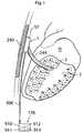
- FIG. 1shows an implantable device for improving the pump function of the heart in a lateral view.
- FIG. 2shows an implantable device for improving the pump function of the heart in a frontal view.
- FIG. 3shows an implantable device for improving the pump function of the heart in a lateral view.
- FIG. 4shows an implantable device for improving the pump function of the heart in a lateral view.
- FIG. 5shows an implantable device for improving the pump function of the heart in a frontal view.
- FIG. 6shows an implantable device for improving the pump function of the heart in a lateral view.
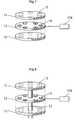
- FIG. 7shows an operating device in detail.
- FIG. 8shows an operating device in detail.
- FIG. 9shows an implantable device for improving the pump function of the heart in a lateral view.
- FIG. 10shows an implantable device for improving the pump function of the heart in a lateral view.
- FIG. 11shows an implantable device for improving the pump function of the heart in a frontal view.
- FIG. 12shows an implantable device for improving the pump function of the heart in a frontal view.
- FIG. 13shows an implantable device for improving the pump function of the heart in a lateral view.
- FIG. 14shows, schematically, a system for transferring force.
- FIG. 15shows, schematically, a system for transferring force.
- FIG. 16shows, schematically, a system for transferring force.
- FIG. 17shows, schematically, how force is exerted on a heart.
- FIG. 18shows, schematically, how force is exerted on a heart.
- FIG. 19shows, schematically, how force is exerted on a heart.
- FIG. 20shows, schematically, how force is exerted on a heart.
- FIG. 21shows an implantable device for improving the pump function of the heart in a frontal view.
- FIG. 22shows an implantable device for improving the pump function of the heart in a lateral view.
- FIG. 23shows an implantable device for improving the pump function of the heart in a lateral view.
- FIG. 24shows an implantable device for improving the pump function of the heart in a frontal view.
- FIG. 25shows an implantable device for improving the pump function of the heart in a lateral view.
- FIG. 26shows, schematically, a system for transferring force.
- FIG. 27shows, schematically, a system for transferring force.
- FIG. 28shows, schematically, an operating device and a fixating member.
- FIG. 29shows, schematically, a system for transferring force.
- FIG. 30shows a frontal view of a human patient with an LVAD.
- FIG. 31shows an implanted artificial heart device in a lateral view.
- FIG. 32shows, schematically, a system for transferring force.
- FIG. 33shows, schematically, a system for transferring force.
- FIG. 34shows a frontal view of a human patient with an implanted system for transferring force.
- FIG. 35shows, schematically, a system for transferring force.
- FIG. 36shows, schematically, a system for transferring force.
- FIG. 37shows, schematically, a system for transferring force.
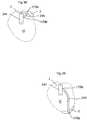
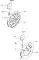
- FIG. 38shows a heart contacting organ in a first position.
- FIG. 39shows a heart contacting organ in a second position.
- FIG. 40shows a heart contacting organ in detail.
- FIG. 41shows a heart contacting organ in detail.
- FIG. 42shows a device for adjusting a heart contacting organ in a first position.
- FIG. 43shows a device for adjusting a heart contacting organ in a second position.
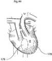
- FIG. 44shows a heart of a human patient in a frontal view.
- FIG. 45shows a system for adjusting the position of a pump device in a first position.
- FIG. 46shows a system for adjusting the position of a pump device in a second position.
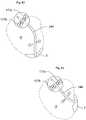
- FIG. 47shows a fixation system
- FIG. 48shows a fixation system
- FIG. 49shows a fixation system
- FIG. 50shows a fixation system
- FIG. 51shows a fixation system
- FIG. 52shows a fixation system
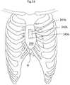
- FIG. 53shows a frontal view of the sternum of a human patient, with a fixating system applied.
- FIG. 54shows a frontal view of the rib cage of a human patient, with a fixating system applied.
- FIG. 55shows a frontal view of the rib cage of a human patient, with a fixating system applied.
- FIG. 56shows a frontal view of the rib cage of a human patient, with a fixating system applied.
- FIG. 57shows a frontal view of the rib cage of a human patient, with a fixating system applied.
- FIG. 58shows a lateral view of the vertebral column of a human patient, with a fixating system applied.
- FIG. 59shows a lateral view of the vertebral column of a human patient, with a fixating system applied.
- FIG. 60shows a frontal view of a part of the vertebral column of a human patient, with a fixating system applied.
- FIG. 61shows an implantable device for improving the pump function of the heart in a lateral view.
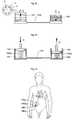
- FIG. 62illustrates a system for treating a disease, wherein the system includes an apparatus implanted in a patient.
- FIGS. 63-77schematically show various embodiments of the system for wirelessly powering the apparatus shown in FIG. 1 .
- FIG. 78is a schematic block diagram illustrating an arrangement for supplying an accurate amount of energy used for the operation of the apparatus shown in FIG. 1 .
- FIG. 79schematically shows an embodiment of the system, in which the apparatus is operated with wire bound energy.
- FIG. 80is a more detailed block diagram of an arrangement for controlling the transmission of wireless energy used for the operation of the apparatus shown in FIG. 1 .
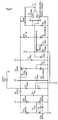
- FIG. 81is a circuit for the arrangement shown in FIG. 62 , according to a possible implementation example.
- FIGS. 82-88show various ways of arranging hydraulic or pneumatic powering of an apparatus implanted in a patient.
- FIG. 89 ashows a sealed chamber comprising an operating device.
- FIG. 89 bshows a sealed chamber for hydraulic use.
- FIG. 90shows a lateral view of a patient when a heart help device is fixated to the sternum of the patient, on the inside thereof.
- FIG. 91shows a lateral view of a patient when a heart help device is fixated to a vertebra of the patient.
- FIG. 92shows a lateral view of a patient when a heart help device is fixated to a rib of the patient.
- FIG. 93 ashows a lateral view of a patient when a heart help device is fixated to the sternum of the patient on the inside thereof, in a diaphragm penetrating way.
- FIG. 93 bshows a lateral view of a patient when a heart help device is fixated to the sternum of the patient, on the outside thereof.
- FIG. 94shows a lateral view of a patient, when a diaphragm contacting part is placed.
- FIG. 95shows a lateral view of a patient, when an opening is created in the thorax of the patient.
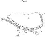
- FIG. 96shows a close-up of a diaphragm contacting part maintaining an opening in the thoracic diaphragm.
- FIG. 97 ashows an embodiment of a heart help device where force is transferred through the thoracic diaphragm.
- FIG. 97 bshows a second embodiment of a heart help device where force is transferred through the thoracic diaphragm.
- FIG. 97 cshows an alternative embodiment of the respiratory movement compensator.
- FIG. 97 dshows an alternative embodiment of the respiratory movement compensator in a second state.
- FIG. 98shows a second embodiment of a heart help device where mechanical and hydraulic force is transferred through the thoracic diaphragm.
- FIG. 99 ashows a first embodiment of a multi-chamber injection port for calibrating elements pressing on the heart.
- FIG. 99 bshows a second embodiment of a multi-chamber injection port.
- FIG. 99 cshows a hydraulic/pneumatic two chamber system.
- FIG. 99 dshows a hydraulic/pneumatic system comprising a selection valve.
- FIG. 99 eshows a hydraulic/pneumatic closed force transferring chamber system comprising a selection valve.
- FIG. 100shows an embodiment of a heart help device in which hydraulic force is transferred through the thoracic diaphragm.
- FIG. 101 ashows an embodiment of a diaphragm contacting part in which the diaphragm contacting part is adapted to be opened, in an open state.
- FIG. 101 bshows an embodiment of a diaphragm contacting part in which the diaphragm contacting part is adapted to be opened, in a closed state.
- FIG. 101 cshows an embodiment of a diaphragm contacting part, which is not possible to open.
- FIG. 101 dshows an embodiment of a diaphragm contacting part, in section.
- FIG. 102shows a diaphragm contacting part, with a force transferring member for transferring of mechanical force placed inside.
- FIG. 103shows a diaphragm contacting part, with two force transferring member for transferring of mechanical force placed inside.
- FIG. 104shows a diaphragm contacting part, with a force transferring member creating a sealing with the diaphragm contacting part placed inside.
- FIG. 105shows a diaphragm contacting part, with a force transferring member for transferring of hydraulic force placed inside.
- FIG. 106shows a diaphragm contacting part, with one force transferring member for transferring of hydraulic, and one force transferring member for transferring hydraulic force placed inside.
- FIG. 107shows a force transferring part for transferring force through the thoracic diaphragm.
- FIG. 108 ashows a displaceable heart help device in a first perspective view.
- FIG. 108 bshows a displaceable heart help device in a second perspective view.
- FIG. 109shows a magnetic operating device in section.
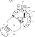
- FIG. 110shows a heart help device comprising a magnetic operating device in a perspective view.
- FIG. 111shows a displaceable heart help device in a first perspective view.
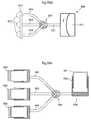
- FIG. 112 ashows a heart help device adapted to be inserted through an opening in the thoracic diaphragm, in its folded state.
- FIG. 112 bshows a heart help device adapted to be inserted through an opening in the thoracic diaphragm, in its unfolded state.
- FIG. 113shows a flow-chart of an operation method for fixation a heart help device.
- ceramic materialis conceivable for entire device parts or parts exposed to wear, example of ceramic materials that can be used for this purpose is: zirconium ceramics or alumina ceramics, partially stabilised zirconia (PSZ), zirconium dioxide, titanium carbide, silicon carbide, sialons/silicon aluminium oxynitrides, boron nitride.
- PSZpartially stabilised zirconia
- zirconium dioxidetitanium carbide
- silicon carbidesilicon carbide
- sialons/silicon aluminium oxynitridessilicon carbide
- boron nitrideboronitride
- the ceramic materialcould further comprise a hydroxy-apatite coating.
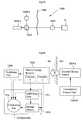
- FIG. 1shows an implantable device 1 for improving the pump function of the heart H of a human patient by applying an external force on the heart muscle.
- the implantable device 1comprises a pump device 3 which comprises an operating device 57 that creates movement of a connecting arm 244 in contact with a heart contacting organ 2 .
- the implantable deviceis adapted to be fixated to a structure of the human body comprising bone 240 .
- the operating device and occasionally occurring other elements that requires control,are controlled from a control unit 176 .
- the control unit 176could comprise an injection port 910 for calibrating a fluid level of a hydraulic system, a battery 911 for supplying energy to the implantable device 1 , a wireless transfer system 912 for transferring energy and/or information to or from the control unit from outside of the human body and at least one sensor 913 for sensing a variable of the implantable device 1 or the patient.
- the control unitcommunicates with the pump device 3 and other elements of the implantable device 1 through a connecting member 906 . However it is also conceivable that the communication could be wireless.
- FIG. 2shows an implantable device 1 for improving the pump function of the heart H of a human patient by applying an external force on the heart muscle.
- the implantable device 1comprises a pump device 3 which comprises an operating device 57 adapted to create a rotating movement through successive energizing coils 14 placed on a first plate 11 which is displaceable in relation to a second plate 12 comprising magnets 15 .
- the magnetic field created between said coils 14 and said magnets 15create a rotating movement of the second plate 12 in relation to the first plate 11 .
- the operating deviceis in connection with a first and second heart contacting organ 2 a,b .
- the first heart contacting organ 2 ais attached to the second plate 12 and thereby moves in relation to the second heart contacting organ 2 b which is fixedly attached to the pump device 3 .
- the second heart contacting organ 2 bserves as a dolly.
- the first and second heart contacting organs 2 a,bexerts a force on the heart H from the left and right sides of the heart H which compresses the heart H and assist the pump function of the heart H.
- FIG. 3shows the implantable device 1 according to an embodiment where the pump device 3 is adapted to exert force on the heart H from the anterior A and posterior P side of the heart H.
- the implantable device 1comprises a connecting arm 244 which attaches the pump device 3 to a fixating member 241 a , which in turn is in contact with a first plate 242 a , which is fixated to a second plate 242 b of a second fixating member 241 b located on the posterior side of a structure of the human body comprising bone 240 .
- the first and second fixating membersclamp the structure of the human body comprising bone 240 and thereby create the fixation of the implantable device 1 .
- the first heart contacting organ 2 ais attached to the second plate 12 and thereby moves in relation to the second heart contacting organ 2 b which is fixedly attached to the pump device 3 .
- the second heart contacting organ 2 bserves as a dolly.
- the first and second heart contacting organsexerts a force on the heart H from the anterior A and posterior P sides of the heart H which compresses the heart H and assist the pump function of the heart H.
- FIG. 4shows the implantable device 1 in a lateral view where the operating device 57 comprising a first plate 11 comprising magnets 15 , a second plate 12 comprising coils and a third plate 13 comprising magnets 15 .
- the successive energizing of the coils 14 of the second plate 12creates rotational movement of both the first and third plate by the magnetic contact created between the coils 14 and the magnets 15 .
- the movementis transferred to the heart contacting organ 2 which in turn exerts force on the heart H.
- FIG. 5shows the implantable device 1 in a frontal view where the operating device 57 comprising a first plate 11 comprising magnets 15 , a second plate 12 comprising coils and a third plate 13 comprising magnets 15 .
- the successive energizing of the coils 14 of the second plate 12creates rotational movement of both the first and third plate by the magnetic contact created between the coils 14 and the magnets 15 .
- the first heart contacting organ 2 ais fixated to the first plate 11
- the second heart contacting organ 2 bis fixated to the third plate 13 .
- the movementis transferred to the heart contacting organs 2 a,b which in turn exerts force on the right and left sides of the heart H, which compresses the heart H and assist the pump function of the heart H.
- FIG. 6shows the implantable device 1 according to an embodiment where the pump device 3 is adapted to exert force on the heart H from the anterior A and posterior P side of the heart H.
- the implantable device 1comprises a connecting arm 244 which attaches the pump device 3 to a fixating member 241 a , which in turn is in contact with a first plate 242 a , which is fixated to a second plate 242 b of a second fixating member 241 b located on the posterior side of a structure of the human body comprising bone 240 .
- the first and second fixating membersclamp the structure of the human body comprising bone 240 and thereby create the fixation of the implantable device 1 .
- the first heart contacting organ 2 ais fixated to the first plate
- the second heart contacting organ 2 bis fixated to the third plate.
- the movementis transferred to the heart contacting organs 2 a,b which in turn exerts force on the anterior A and posterior P sides of the heart H, which compresses the heart H and assist the pump function of the heart H.
- FIG. 7shows the operating device 57 is further detail wherein the operating device 57 comprises a first part comprising a plate 11 with a first surface, a second part comprising a second plate 12 having a second surface and a third part comprising a third plate 13 having a third surface.
- the first, second and third partsare displaceable in relation to each other and adapted for rotating movement.
- the second plate 12comprises coils 14 whereas the first and third plate comprises magnets 15 .
- the coilscan be successively energized, controlled from a control unit 176 , which creates movement of the first and third plates by the magnetic connection between the coils 14 and magnets 15 .
- the surfaces of the first and second plate 11 , 12abut each other and is in substantially constant movement which hinders any growth of scar tissue that could interrupt the function of the operation device 57 .
- the plates 11 , 12 , 13or alternatively the surfaces, needs to be made of a highly durable material.
- a materialcould be a ceramic material, a carbon based material or a metallic material such as titanium or stainless steel.
- the plates or surfacesis made of a self lubricating material such as a fluorpolymer, alternatively the surfaces could be adapted to be lubricated by means of an implantable lubricating system.
- the implantable lubricating systemcould be adapted to lubricate the plates 11 , 12 , 13 or surfaces with a biocompatible lubricating fluid such as hyaluronic acid. A combination of mentioned materials is further conceivable.
- the operating device 57is according to the embodiment in FIG. 7 adapter for rotational movement, however it is possible that the operation device is adapted for reciprocating movement.
- FIG. 8shows the operating device 57 is further detail wherein the operating device 57 comprises a first part comprising a plate 11 with a first surface, a second part comprising a second plate 12 having a second surface and a third part comprising a third plate 13 having a third surface.
- the first, second and third partsare displaceable in relation to each other and adapted for rotational movement.
- the second plate 12comprises coils 14 whereas the first and third plate comprises magnets 15 .
- the coilscan be successively energized, controlled from a control unit 176 , which creates movement of the first and third plates by the magnetic connection between the coils 14 and magnets 15 .
- the operating devicefurther comprises a centre axis 17 which guides the rotational movement of the operating device 57 .
- FIG. 9shows a lateral view of an embodiment where the implantable device 1 comprises a pump device 3 .
- the pump device 3comprises a piston 50 adapted for reciprocating movement placed in connection with an operating device 51 for operating the piston 50 .
- the piston 50is in turn in contact with a heart contacting organ 2 which in turn is in contact with the heart H of a human patient.
- the implantable devicecould in FIG. 9 further comprise a second pump device 53 , the first and second pump devices are adapted to operate on the left and right side of the human heart H respectively, however in other embodiments the first and second pump devices 3 , 53 could be adapted to operate on the anterior and the posterior side of the heart H of a human patient.
- the implantable device 1further comprises a first and second fixating member 241 a,b adapted to fixate said implantable device 1 to a structure of the human body comprising bone 240 .
- the fixating memberscomprises a first and second plate 242 a,b which are fixated to each other using screws.
- a highly durable materialsuch as a material could be a ceramic material, a carbon based material or a metallic material such as titanium or stainless steel.
- parts or surfacesis made of a self lubricating material such as a fluorpolymer
- the surfacescould be adapted to be lubricated by means of an implantable lubricating system.
- the implantable lubricating systemcould be adapted to lubricate parts or surfaces with a biocompatible lubricating fluid such as hyaluronic acid.
- a biocompatible lubricating fluidsuch as hyaluronic acid.
- the deviceis in substantially constant movement which hinders any growth of scar tissue that could interrupt the function of the device.
- FIG. 10shows a lateral view of an embodiment where the implantable device 1 is adapted for exerting force on the anterior and posterior side of the human heart H.
- the two heart contacting organs 2 a,bare adapted to exert force on the heart H through the connection with the piston 50 a adapted for reciprocating movement.
- both the heart contacting organ 2 a and the heart contacting organ 2 bis hinged 52 to the pump device 3 which enables both heart contacting organs 2 a,b to move and exert force on the heart H.
- the piston 50 ais according to this embodiment a piston adapted to create movement in two directions, which enables two heart contacting organs 2 a,b to be operable by means of only one pump device 3 . It is however conceivable that the piston 50 a is of a type adapted to create movement in one direction 50 b in which case two pump devices 3 , 53 could be provided to enable two heart contacting organs 2 a,b to be operable.
- FIG. 11shows a frontal view of the implantable device 1 according to the embodiment shown in FIG. 5A .
- the pump device 3is here adapted to exert force on the heart H from the right and left side of the heart H through the heart contacting organs 2 a,b hinged 52 to the pump device 3 .
- the piston 50 ais according to this embodiment a piston adapted to create movement in two directions, which enables two heart contacting organs 2 a,b to be operable by means of only one pump device 3 . It is however conceivable that the piston 50 a is of a type adapted to create movement in one direction 50 b in which case two pump devices 3 , 53 could be provided to enable two heart contacting organs 2 a,b to be operable.
- the first and second heart contacting organs 2 a,bpresses the heart towards each other which exerts a force on the heart H improving the pump function of the heart H.
- FIG. 12shows a frontal view of the implantable device 1 according to an embodiment where a piston 50 b is adapted to create movement in one direction.
- the second heart contacting organ 2 bis hinged 52 to the implantable device 1
- the first heart contacting organ 2 ais fixedly attached to the implantable device 1 .
- the second heart contacting organ 2 bpresses the heart towards the first heart contacting organ 2 a which exerts a force on the heart H improving the pump function of the heart H.
- FIG. 13shows a lateral view of an embodiment where the implantable device 1 is adapted for exerting force on the anterior and posterior side of the human heart H.
- the second heart contacting organ 2 bis hinged 52 to the implantable device 1
- the first heart contacting organ 2 ais fixedly attached to the implantable device 1 .
- the piston 50 bis adapted to create movement in one direction and operates the second heart contacting organ 2 b to exert force on the heart H from the anterior and posterior side of the heart through the second heart contacting organ 2 b pressing the heart H against the first heart contacting organ 2 a .
- the pump device 3is attached to a connecting arm 244 which in turn is connected to the first fixating member 241 a attached to the first plate 242 a which is fixated to a structure of the human body comprising bone 240 through the connection with the second plate 242 b of the second fixating member 241 b.
- FIG. 14shows an embodiment where the implantable device 1 comprises a system for transferring of force from a remote location R to a distribution location D.
- the heart contacting organ 2is a section of the force distributing piston 50 which exerts force on the heart H, the force is transferred via a force transferring system 56 , which could be a hydraulic, mechanic or pneumatic force transferring system 56 .
- the forceis created using an operating device 57 , in this embodiment the operating device 57 is an electric motor, however it is also conceivable that motor is a hydraulic or pneumatic motor.
- the force generated by the operating deviceis then transferred to an eccentric member 58 which creates a reciprocal movement in a second piston 55 .
- the reciprocating movement created in the second piston 55it then transferred through the force transferring system 56 to the first piston 50 which is placed in reciprocating movement, and in turn exerts force on the heart H through the connection with the heart contacting organ 2 .
- the first and second pistons 50 , 55are protected by a protective layer 54 which is made of a flexible material.
- the protective layer 54hinders scar tissue to form in proximity to the moving parts, which could hinder the operation of the pistons 50 , 55 .
- the operating device 57 and additional parts of the system that could require controlis controlled through the control unit 176 , which in turn could be adapted to be wirelessly controlled from outside of the human body.
- FIG. 15shows an embodiment where the operating device 57 is an operating device adapted to create a rotating movement through successive energizing coils 14 placed on a first plate which is displaceable in relation to a second plate comprising magnets 15 .
- the magnetic field created between said coils 14 and said magnets 15creates a rotating movement of the second plate in relation to the first plate.
- a mechanical force transferring member 59is attached to the second plate and hinged 60 to the piston 50 .
- the pistonin turn comprises the heart contacting organ 2 which exerts force on the heart H through the connection with the operating device 57 .
- a control unit 176 for controlling the operating deviceis also provided, which in turn could be adapted to be wirelessly controlled from outside of the human body.
- FIG. 16shows an embodiment where the operating device 57 is a solenoid adapted to create a reciprocating movement of the piston 50 in connection with the heart contacting organ 2 to exert a force on the heart H of a human patient.
- a control unit 176 for controlling the operating device 57is also provided, which in turn could be adapted to be wirelessly controlled from outside of the human body.
- FIG. 17shows, schematically, how a piston 50 housed in a protective layer 54 exerts force on the heart H of a human patient through the connection with a heart contacting organ 2 .
- the piston 50is adapted to create reciprocating movement in two directions, the movement in the first direction is powered and the movement in the second direction could either be powered of created with a spring placed in relation to the piston 50 .
- FIG. 18shows, schematically, how a piston 50 housed in a protective layer 54 exerts force on the heart H of a human patient through a mechanical force transferring system 59 which comprises a hinged joint 60 .
- the mechanical force transferring systemcomprises a heart contacting organ 2 which in turn exerts force on the heart of a human patient H through the connection with the mechanical force transferring system 59 and the piston 50 adapted for reciprocating movement.
- FIG. 19shows, schematically, how two pistons 50 a,b exerts force on the heart of a human patient H from the left and right side of the heart H.
- Each of the two pistonscomprises a heart contacting organ 2 a,b which exerts force on the heart H to compress the heart H to assist the pump function thereof.
- the two pistons 2 a,bcould be adapted to be placed on the anterior and posterior side of the heart H, or be movable to enable postoperative change in the position of the force exerted on the heart H.
- FIG. 20shows, schematically, how a piston 50 exerts force on the heart of a human patient through the connection with a heart contacting organ 2 a from one side of the heart H.
- a second heart contacting organ 2 bif fixedly attached to the implantable device 1 and serves as a dolly 61 to enable the implantable device 1 to exert force on the heart H.
- FIG. 21shows a frontal view of an implantable device 1 for improving the pump function of the heart of a human patient according to an embodiment wherein the implantable device comprises a pump device 3 comprises a rotating member 93 having a rotating centre.
- a driving member 91is attached to the rotating member 93 and adapted to perform an eccentric movement in relation to the rotating center of said rotating member 93 .
- the driving member 91is in contact with a heart contacting organ 2 a,b which in turn is adapted to exert force on the heart H of a human patient.
- the pump devicefurther comprises an operating device 57 for operating the driving member 91 .
- the operating deviceis in connection with the rotating member through a force transferring member 92 which for example could be a band, cord or chain.
- the operating device 57could be an electric, hydraulic or pneumatic motor, and could be adapted to be controlled from outside of the human body.
- a highly durable materialcould be a ceramic material, a carbon based material or a metallic material such as titanium or stainless steel.
- parts or surfacesis made of a self lubricating material such as a fluorpolymer, alternatively the surfaces could be adapted to be lubricated by means of an implantable lubricating system.
- the implantable lubricating systemcould be adapted to lubricate parts or surfaces with a biocompatible lubricating fluid such as hyaluronic acid. A combination of mentioned materials is further conceivable.
- the deviceis in substantially constant movement which hinders any growth of scar tissue that could interrupt the function of the device.
- FIG. 22shows a lateral view of an implantable device 1 for improving the pump function of the heart of a human patient according to an embodiment wherein the implantable device comprises a pump device 3 comprises a rotating member 93 having a rotating centre.
- a driving member 91is attached to the rotating member 93 and adapted to perform an eccentric movement in relation to the rotating center of said rotating member 93 .
- the driving member 91is in contact with a heart contacting organ 2 a,b which in turn is adapted to exert force on the heart H of a human patient.
- the pump devicefurther comprises an operating device 57 for operating the driving member 91 .
- the operating deviceis in connection with the rotating member through a force transferring member 92 which for example could be a band, cord or chain.
- the operating device 57could be an electric, hydraulic or pneumatic motor, and could be adapted to be controlled from outside of the human body.
- the pump device 3is attached to a connecting arm 244 which in turn is connected to a fixating member 241 which is fixated to a structure of the human body comprising bone 240 .
- the first heart contacting organis fixedly attached to the pump device 3 and serves as a dolly, whereas the second heart contacting organ is hinged to exert the force on the heart H.
- FIG. 23shows a lateral view of the implantable device 1 described in FIG. 21 where the pump device is adapted to exert force on the heart H from the right and left side of the heart H.
- the driving member 91is in contact with an operating device 57 .
- FIG. 24shows a frontal view of the pump device 3 wherein both the first heart contacting organ 2 a and the second heart contacting organ 2 b are hinged to the pump device 3 which enables the heart contacting organs 2 a,b to exert force on the heart H, assisting the pump function thereof, from the right and left side of the heart H.
- the driving member 91is according to this embodiment designed to operate two heart contacting organs 2 a,b through the connection with the operating device 57 .
- FIG. 25shows a lateral view of the pump device 3 wherein both the first heart contacting organ 2 a and the second heart contacting organ 2 b are hinged to the pump device 3 , which enables the heart contacting organs 2 a,b to exert force on the heart H, assisting the pump function thereof, from the anterior and posterior side the heart H.
- the driving member 91is according to this embodiment designed to operate two heart contacting organs 2 a,b through the connection with the operating device 57 .
- the pump device 3is attached to a connecting arm 244 which in turn is connected to a fixating member 241 which is fixated to a structure of the human body comprising bone 240 .
- FIG. 26shows, schematically, an embodiment of a pump device according to any of the embodiments.
- An operating device 57operates a rotating member 93 having a rotating centre which is attached to a driving member 91 adapted to create an eccentric movement.
- the driving memberis in contact with a pivot 100 which is hinged 101 .
- the pivotcould serve as a mechanical transmitter of force, or as a heart contacting organ 2 adapter to exert force on the heart H of a human patient.
- the operating deviceis controlled using a control unit 176 connected to the operating device through a connecting member 906 .
- the operating devicecould be an electric, magnetic, hydraulic or pneumatic motor.
- an injection port 97could be provided to enable the calibration of fluid in the hydraulic system.
- the control unit 176could further comprise at least one sensor 98 for sensing a variable of the device, or the patient. Furthermore the control unit 176 could comprise a wireless transfer unit 99 for transferring of wireless energy and/or information. At least one battery 106 could also be provided in the control unit.
- FIG. 27shows, schematically, an embodiment of a pump device according to any of the embodiments.
- An operating device 57operates a rotating member 93 having a rotating centre which is attached to a driving member 91 adapted to create an eccentric movement.
- the driving memberis in contact with a pivot 100 which is hinged 101 in one end, the other end is in contact with another pivot 103 which is hinged in its other end 107 .
- the pivot system that the first and second pivot 100 , 103could be used as a mechanical transmitter of force, or said first or second pivot could comprise a heart contacting organ 2 adapted to exert force on the heart H.
- FIG. 28shows, schematically, an embodiment of a pump device 3 , where the pump device 3 comprises a fixating member 241 which is adapted to fixate the pump device 3 to a structure of the human body comprising bone 240 .
- the fixating memberis adapted to fixate the pump device 3 to a structure of the human body comprising bone 240 using screws 243 .
- FIG. 29shows, schematically, an embodiment of a pump device according to any of the embodiments.
- An operating device 57operates a rotating member 93 having a rotating centre which is attached to a driving member 91 adapted to create an eccentric movement.
- the driving memberis in contact with a reciprocating member 104 which is guided by two guiding members 105 a,b .
- the reciprocating member 104could be used as a mechanical transmitter of force, or comprising a heart contacting organ 2 adapted to exert force on the heart H.
- FIG. 30shows a frontal view of a human patient according to an embodiment where the implanted device 1 is an LVAD 130 (Left Ventricular Assist Device).
- the LVADcan be fixated to a structure of the human body comprising bone 240 according to any of the embodiments described.
- FIG. 31shows a frontal view of a human patient according to an embodiment where the implanted device 1 is an artificial heart device 131 .
- the artificial heart device 131can be fixated to a structure of the human body comprising bone 240 according to any of the embodiments described.
- FIG. 32schematically shows a closed pneumatic or hydraulic implantable system for transferring force from a remote location R to a distribution location D.
- the systemcomprises a first reservoir in the form of a first bellows 141 in contact with an operating device 57 , which in this embodiment is an operating device comprising coils 14 and magnets 15 , which is described in further detail previously.
- the volume of the first bellows 141is affected by the contact with the operating device 57 which causes a fluid to be transferred in the fluid connection 142 , which in turn affects the second bellows 140 on the distribution location.
- the second bellowscould be used as a mechanical force transmitter or could be provided with a heart contacting organ 2 for exerting force on the heart of a human patient H.
- the implantable systemis adapted to allow free flow of fluid between said first bellows 141 and said second bellows.
- FIG. 33schematically shows a closed pneumatic or hydraulic implantable system for transferring force from a remote location R to a distribution location D.
- the systemcomprises a first reservoir in the form of a first piston 144 .
- the volume in the cylinder 147 of the first piston 144is affected by the contact with an operating device which causes a fluid to be transferred in the fluid connection 142 , which in turn affects the second piston 143 on the distribution location, through the change of the fluid volume in the second cylinder 148 .
- the second piston 143could be used as a mechanical force transmitter or could be provided with a heart contacting organ 2 for exerting force on the heart of a human patient H.
- the implantable systemis adapted to allow free flow of fluid between said first bellows 141 and said second bellows.
- the systemcould be adapted to operate using pressurized fluid in one direction and vacuum in the other direction, or pressurized fluid in both directions. It is also conceivable that the first an second pistons 143 , 144 operates by means of a spring 145 a,b in one direction.
- FIG. 34shows a frontal view of a patient where the remote location R of the implantable system for transferring force from a remote location R to a distribution location D, is located in the abdominal region and the distribution location is located in connection with the heart H.
- the remote locationcomprises a control unit which in turn could comprise an operating device 146 a , an injection port 146 b , a battery 146 c and at least one sensor 146 d for sensing a variable of the implantable system or the patient.
- FIG. 35schematically shows a closed pneumatic or hydraulic implantable system for transferring force from a remote location R to a distribution location D.
- the systemcomprises a first reservoir in the form of a first bellows 141 an a second reservoir in form of a second bellows 140 .
- the first and second bellowsare connected through a fluid connection 142 .
- the fluid connectionis adapted to always allow free flow of fluid between the first and second reservoir.
- FIG. 36schematically shows a closed pneumatic or hydraulic implantable system for transferring force from a remote location R to a distribution location D.
- the systemcomprises a first reservoir in the form of a first bellows 141 an a second reservoir in form of a second bellows 140 .
- the first and second bellowsare connected through a fluid connection 142 .
- the fluid connectionis adapted to always allow free flow of fluid between the first and second reservoir.
- the systemis operated using pressurized fluid in one direction and spring force from a spring 145 b in the second bellows in opposite direction.
- FIG. 37schematically shows a closed pneumatic or hydraulic implantable system for transferring force from a remote location R to a distribution location D.
- the systemcomprises a first reservoir in the form of a first bellows 141 in contact with an operating device 57 , which in this embodiment is an operating device comprising a rotating member 93 having a rotating centre which is attached to a driving member 93 adapted to create an eccentric movement affecting the first bellows.
- the volume of the first bellows 141is affected by the contact with the operating device 57 which causes a fluid to be transferred in the fluid connection 142 , which in turn affects the second bellows 140 on the distribution location.
- the second bellowscould be used as a mechanical force transmitter or could be provided with a heart contacting organ 2 for exerting force on the heart of a human patient H.
- the implantable systemis adapted to allow free flow of fluid between said first bellows 141 and said second bellows 140 .
- a heart contacting organ 2could be adapted to change the position of the force exerted on the heart H of a human patient. This could be done by adjusting the position of the heart contacting organ 2 in relation to a fixating member 241 that fixates an implantable device 1 comprising the heart contacting organ 2 to a structure of the human body comprising bone 240 . The adjustment could be performed by moving a connecting arm which is fixated to the fixating member 241 and the heart contacting organ 2 .
- the object of moving the heart contacting organ 2could be to increase the blood flow to area on which the heart contacting organ 2 exerts force. It could also be to improve the positioning of the heart contacting organ 2 such that the ability of the implantable device 1 to assist the pump function of the heart H. It could further be to relive the patient of any discomfort that the implantable device 1 might cause him/her.
- FIG. 38shows an embodiment in which the heart contacting organ 2 is attached to a connecting arm 244 in connection with the heart contacting organ 2 and the fixating member 241 .
- the connecting arm 244is hinged 170 a,b to both the heart contacting organ 2 and the fixating member 241 .
- the connecting arm 244is hinged to one of the points 170 a and 170 b and fixedly attached to the other 170 a,b respectively.
- the connecting arm 244could be adapted to be operable either manually or powered.
- the connecting armcould be operable by means of an operation device 172 which could be an electric, a mechanical, a hydraulic or a pneumatic operating device 172 .
- the operating device 172could be placed in connection with the fixating member 241 and could be adapter to be remotely controlled from outside of the human body using a remote control. It is also conceivable that the connecting arm could be manually adjusted during a surgical or laparoscopic procedure in which case an adjusting member (not shown) could be provided to the implantable device 1 .
- the adjusting membercould be one that is adjustable by means of a surgical tool used in the surgical or laparoscopic procedure.
- FIG. 39shows an embodiment where the heart contacting organ 2 has been moved from the position in which it is placed in FIG. 38 . The position of the force exerted on the heart H is thereby moved.
- the elementscould be pistons 173 and/or cushions 171 which could be electrically, mechanically, hydraulically or pneumatically operated.
- the pistons 173 and/or cushions 171could be adapter to be remotely controlled from outside of the human body using a remote control. It is also conceivable that the pistons 173 and/or cushions 171 could be manually adjusted during a surgical or laparoscopic procedure.
- the heart contacting organcould comprise cushions 171 exclusively, pistons 173 exclusively or a mixture thereof.
- FIG. 40shows an embodiment in which multiple cushions 171 are placed on the heart contacting organ 2 .
- the cushions 171could be raised and lowered in relation to the heart contacting organ 2 to change the position of the force exerted on the heart H.
- FIG. 17Cfurther shows a connecting arm 244 in connection with an operating device 172 for adjusting the location of the heart contacting organ 2 in relation to the heart H.
- the operating device 172could be electrically, mechanically, hydraulically or pneumatically operated and could be adapter to be remotely controlled from outside of the human body using a remote control. It is also conceivable that the connecting arm 244 could be manually adjusted during a surgical or laparoscopic procedure.
- the implantable devicecould further comprise a hydraulic or pneumatic system (not shown) for changing the volume of the cushion 171 or the volume under the piston 173 , by moving a hydraulic or pneumatic fluid to or from the cushion 171 .
- FIG. 41shows an embodiment where the heart contacting organ 2 comprises a cushion 174 that exerts force in the heart H.
- the cushion 174can be moved on the heart contacting organ 2 to change the position of the force exerted on the heart H.
- the heart contacting organfurther comprises a rotational element 175 that rotates to create the movement of the cushion 174 on the great contacting organ 2 .
- the rotational elementcould be operable manually, electrically, mechanically, hydraulically or pneumatically, and can further be adapted to be remotely controlled from outside of the human body using a remote control.
- FIG. 17Dfurther shows a connecting arm 244 in connection with an operating device 172 for adjusting the location of the heart contacting organ 2 in relation to the heart H.
- the operating device 172could be electrically, mechanically, hydraulically or pneumatically operated and could be adapter to be remotely controlled from outside of the human body using a remote control.
- FIG. 42shows the embodiment according to FIG. 38 when implanted in a human body.
- the heart contacting organ 2comprising cushions 171 and/or pistons 173 which could be raised and lowered in relation to the heart contacting organ to change the position of the force exerted on the heart H.
- the implantable devicefurther comprises a connecting arm 244 in contact with the heart contacting organ 2 and an operating device 172 for operating the connecting arm 244 .
- the operating deviceis in contact with the pate of the first fixating member 242 a that together with the second fixating member 242 b fixates the implantable device to a structure of the human body comprising bone 240 .
- the implantable devicefurther comprises a control unit 176 for controlling the heart pump device, the operating device 172 and the cushions 171 and/or pistons 173 placed on the heart contacting organ 2 .
- FIG. 43shows an embodiment where the heart contacting organ 2 is operable to change the position of the force exerted on the heart H using two operating devices 177 a,b the two operating devices could be mechanical, hydraulic or pneumatic devices.
- the heart contacting organis operable through the connection with the operating device through the connecting arm 244 hinged to the heart contacting organ and the implantable device comprising the two operating devices 177 a,b .
- the connecting arm 244is operable using only one operating device, in which case that operating device could be adapted for powered movement in two directions, or adapted for powered movement in one direction and spring loaded movement in the other direction.
- FIG. 44shows the heart H of a human patient H in a frontal view wherein 179 indicates the right ventricle which is a possible position for exerting force, and 178 indicates the left ventricle which also is a possible position for exerting force. It is also conceivable that force could be exerted on two different sides of the right 179 or left 178 ventricle, respectively.
- FIG. 45shows the implantable device 1 according to an embodiment where a pump device 3 is placed on an adjustment system comprising a first fixating member 241 , a second fixating member 185 and a third fixating member 186 .
- the first fixating member 241is adapter for fixation in a structure of the human body comprising bone 240 .
- the first fixating membercomprises a first trench wherein the second fixating member 185 is adapted to move.
- the second fixating member 185in turn comprises a second trench wherein the third fixating member 186 is adapted to move.
- the third fixating member 186comprises a piston 182 which can be raised and lowered for adjusting the pump device 1 in a third axis.
- the third fixating membercomprises a surface 183 to which the pump device 3 can be fixated.
- the pump device 3can be adjusted three dimensionally which can change the position of the force exerted on the heart H.
- the adjustment systemcan be operable by means of an implantable motor, the motor could be an electric, hydraulic or pneumatic motor.
- the motorcould be adapted to be remotely controlled from outside of the human body using a remote control.
- the pump device 3could hence be post-operatively adjusted by the patient or by a physician.
- the position of the pump device 3could be verified from the outside of the human body using x-ray or ultra-sound.
- FIG. 46shows the adjustable system described in FIG. 17H in a second position.
- FIG. 47-60shows the fixation of an implantable device to a structure of the human body comprising bone 240 .
- the structurecould be the sternum, a part of the rib cage, comprising one or more ribs or a part of the vertebral column comprising at least one vertebra.
- the implantable device 1is fixated to the structure of the human body comprising bone 240 trough a fixating member 241 said fixating member could comprise a plate 242 which is in contact with the structure of the human body comprising bone 240 .
- the implantable device 1could also be fixated to the structure of the human body comprising bone 240 using a second fixating member 241 b which also could comprise a plate 242 b in which in turn could be in contact with the structure of the human body comprising bone 240 .
- FIG. 47shows an embodiment where the implantable device 1 is fixated to a structure of the human body comprising bone 240 .
- the structurecould be the sternum, a part of the rib cage comprising one or more ribs or a part of the vertebral column structure comprising at least one vertebra.
- the implantable device 1comprises a first fixating member 241 a comprising a plate 242 a and a second fixating member 241 b comprising a plate 242 b .
- the first and second fixating membersare attached to each other using through-going screws 243 placed from the anterior side A of the structure of the human body comprising bone 240 .
- An alternative embodimentcould comprise screws placed from the posterior side P of the structure of the human body comprising bone 240 .
- the first fixating member 241 a and the second fixating member 241 bclamp the structure of the human body comprising bone 240 .
- the fixating member 241 acould be in contact with a connecting arm 244 which in turn could be in contact with a heart pump device.
- FIG. 48shows an embodiment where the implantable device 1 is fixated to a structure of the human body comprising bone 240 using only one fixating member 241 a comprising a plate 242 a .
- the structurecould be the sternum, a part of the rib cage comprising one or more ribs or a part of the vertebral column structure comprising at least one vertebra.
- Through-going screws 243is placed form the anterior side A the structure of the human body comprising bone 240 and fixated in the plate 242 a .
- An alternative embodimentcould comprise screws placed from the posterior side P of the structure of the human body comprising bone 240 in which case the screws could be fixated in nuts placed in connection with the structure of the human body comprising bone, or fixated in directly in the bone of the structure of the human body comprising bone 240 .
- the fixating member 241 acould be in contact with a connecting arm 244 which in turn could be in contact with a heart pump device.
- FIG. 49shows an embodiment where the implantable device 1 is fixated to a structure of the human body comprising bone 240 .
- the structurecould be the sternum, a part of the rib cage comprising one or more ribs or a part of the vertebral column comprising at least one vertebra.
- the implantable device 1comprises a first fixating member 241 a comprising a plate 242 a and a second fixating member 241 b comprising a plate 242 b .
- the first and second fixating membersare attached to each other using through-going screws 243 placed from the posterior side P of the structure of the human body comprising bone 240 .
- the screwsare fixated to nuts 245 placed on the anterior side of the structure comprising bone 240 .
- An alternative embodimentcould comprise screws placed from the anterior side A of the structure of the human body comprising bone 240 , in which case the nuts is placed on the posterior side P of the structure comprising bone 240 .
- the first fixating member 241 a and the second fixating member 241 bclamp the structure of the human body comprising bone 240 .
- the fixating member 241 acould be in contact with a connecting arm 244 which in turn could be in contact with a heart pump device.
- FIG. 50shows an embodiment where the implantable device 1 is fixated to a structure of the human body comprising bone 240 using only one fixating member 241 a comprising a plate 242 a .
- the structurecould be the sternum, a part of the rib cage comprising one or more ribs or a part of the vertebral column structure comprising at least one vertebra.
- Screws 243 that fixates the fixating member to the structure of the human body comprising boneis placed form the posterior side P the structure of the human body comprising bone 240 .
- the screwsfixates the fixating member to both the posterior and the anterior cortex of the structure of the human body comprising bone 240 , however it is conceivable that the screws are fixated only to the anterior or posterior cortex.
- An alternative embodimentcould comprise screws placed from the anterior side A of the structure of the human body comprising bone 240 , in which case the fixating member 241 a is placed on the anterior side A of the structure of the human body comprising bone 240 .
- FIG. 51shows an embodiment where the implantable device 1 is fixated to a structure of the human body comprising bone 240 using one fixating member 241 b comprising a plate 242 b , and one fixating member 241 a without a plate.
- the structurecould be the sternum, a part of the rib cage comprising one or more ribs or a part of the vertebral column structure comprising at least one vertebra.
- Screws 243 that fixates the fixating members 241 a,b to the structure of the human body comprising bone 240is placed form the anterior side A of the structure of the human body comprising bone 240 and fixated in the fixating member 241 a .
- the first fixating member 241 a and the second fixating member 241 bclamp the structure of the human body comprising bone 240 .
- the fixating member 241 acould be in contact with a connecting arm 244 which in turn could be in contact with a heart pump device.
- FIG. 52shows an embodiment where the implantable device 1 is fixated to a structure of the human body comprising bone 240 using one fixating member 241 b comprising a plate 242 b , and one fixating member 241 a without a plate.
- the structurecould be the sternum, a part of the rib cage comprising one or more ribs or a part of the vertebral column structure comprising at least one vertebra.
- Screws 243 that fixates the fixating members 241 a,b to the structure of the human body comprising bone 240is placed form the posterior side P of the structure of the human body comprising bone 240 and fixated in the plate 242 b of the fixating member 241 b .
- the first fixating member 241 a and the second fixating member 241 bclamp the structure of the human body comprising bone 240 .
- the fixating member 241 acould be in contact with a connecting arm 244 which in turn could be in contact with a heart pump device.
- FIG. 53shows an embodiment where the implantable device 1 is adapted to be fixated to the sternum 250 of a human patient.
- the deviceis fixated using a fixating member 241 b which is fixated to the sternum using screws 243 .
- the implantable devicecould be fixated to the sternum 250 of a human patent using any of the ways to place the fixating members described previously.
- FIG. 54shows an embodiment where the implantable device 1 is adapted to be fixated to two ribs 251 , 252 .
- a fixating member 241comprising a plate 242 b is fixated with screws adapted to fixate the fixating member to the cortex of the ribs.
- FIG. 55shows an embodiment where the implantable device 1 is adapted to be fixated to two ribs 251 , 252 .
- a first plate 242 ais provided on the posterior side of the rib cage, whereas a second plate 242 b is provided in the anterior side of the rib cage.
- Screws 243penetrate the ribs and fixates the first plate 242 a to the second plate 242 b . The tightening of the screws creates a clamping effect of the ribs 251 , 251 and provides the fixation of the implantable device 1 .
- he screws 243are placed between the ribs 251 , 252 and that ways provides a clamping effect of the ribs 251 , 252 .
- FIG. 56shows an embodiment where the implantable device 1 is adapted to be fixated to one rib 252 .
- a plate 242 ais provided on the posterior side of the rib cage and screws 243 are provided from the outside thereof, penetrating the rib 252 and fixating the plate 242 a to the rib 252 .
- FIG. 57shows an embodiment where the implantable device 1 is adapted to be fixated to one rib 252 using cord or band 254 , this way there is no need to penetrate the rib 252 .
- the implantable devicecould be fixated to the ribcage of a human patent using any of the ways to place the fixating members described previously.
- FIG. 58shows an embodiment where the implantable device 1 is adapted to be fixated to a vertebra 255 of the vertebral column.
- a fixating member 241is fixated to the vertebra 255 using screws 243 .
- the implantable devicefurther comprises a connecting connecting arm 244 that connects the implantable device 1 to the fixating member 241 .
- FIG. 59shows an embodiment where the implantable device 1 is adapted to be fixated to two vertebras 255 , 256 of the vertebral column.
- a fixating member 241is fixated to the two vertebras 255 , 256 using screws 243 .
- the implantable devicefurther comprises a connecting connecting arm 244 that connects the implantable device 1 to the fixating member 241 .
- FIG. 60shows an embodiment where the implantable device is adapted to be fixated to a vertebra 255 of the vertebral column by clamping said vertebra 255 .
- Two fixating members 241 a , 241 bis placed on two sides of the vertebra and an attachment comprising screws 243 clamps the vertebra between the first and second fixating members 241 a,b .
- the implantable devicefurther comprises a connecting connecting arm 244 that connects the implantable device 1 to the fixating member 241 .
- the means of attachmentcould be replaced with other mechanical attachments or an adhesive.
- Other mechanical attachments suitablecould be: pop-rivets, nails, staples, band or cord.
- the mechanical fixating memberscould be of a metallic or ceramic material. Suitable metallic materials could be titanium or surgical steel.
- FIG. 61shows an embodiment where the heart contacting organ 2 is adapted to compress the heart H to assist the pump function thereof.
- a stimulation device 907is attached to the heart contacting organ 2 and is adapted to stimulate the heart H to achieve an additional assistance of said pump function after the heart contacting organ 2 has placed the heart in the compressed state.
- the heart contacting organis attached to a connecting arm 244 which in turn is attached to a mechanical, electrical or hydraulic operating device 172 which operates the heart contacting organ 2 .
- the operating device 172is in turn attached a fixating member which fixates the device to a structure of the human body comprising bone 244 using mechanical fixating members such as screws, or adhesive.
- a control device 176 for controlling the operating device 172 in accordance with any of the embodiments described in this applicationis in connection with said operating device 172 though a connecting member 906 . However it is also conceivable that the control device 176 communicates wirelessly with the operating device 172 .
- FIG. 62illustrates a system for treating a disease comprising an apparatus 10 placed in the abdomen of a patient.
- An implanted energy-transforming device 1002is adapted to supply energy consuming components of the apparatus with energy via a power supply line 1003 .
- An external energy-transmission device 1004 for non-invasively energizing the apparatus 10transmits energy by at least one wireless energy signal.
- the implanted energy-transforming device 1002transforms energy from the wireless energy signal into electric energy which is supplied via the power supply line 1003 .
- the implanted energy-transforming device 1002may also comprise other components, such as: a coil for reception and/or transmission of signals and energy, an antenna for reception and/or transmission of signals, a microcontroller, a charge control unit, optionally comprising an energy storage, such as a capacitor, one or more sensors, such as temperature sensor, pressure sensor, position sensor, motion sensor etc., a transceiver, a motor, optionally including a motor controller, a pump, and other parts for controlling the operation of a medical implant.
- a coilfor reception and/or transmission of signals and energy
- an antennafor reception and/or transmission of signals
- a microcontrollere.g., a microcontroller
- a charge control unitoptionally comprising an energy storage, such as a capacitor
- sensorssuch as temperature sensor, pressure sensor, position sensor, motion sensor etc.
- a transceivere.g., a motor controller, a pump, and other parts for controlling the operation of a medical implant.
- the wireless energy signalmay include a wave signal selected from the following: a sound wave signal, an ultrasound wave signal, an electromagnetic wave signal, an infrared light signal, a visible light signal, an ultra violet light signal, a laser light signal, a micro wave signal, a radio wave signal, an x-ray radiation signal and a gamma radiation signal.
- the wireless energy signalmay include an electric or magnetic field, or a combined electric and magnetic field.
- the wireless energy-transmission device 1004may transmit a carrier signal for carrying the wireless energy signal.
- a carrier signalmay include digital, analogue or a combination of digital and analogue signals.
- the wireless energy signalincludes an analogue or a digital signal, or a combination of an analogue and digital signal.
- the energy-transforming device 1002is provided for transforming wireless energy of a first form transmitted by the energy-transmission device 1004 into energy of a second form, which typically is different from the energy of the first form.
- the implanted apparatus 10is operable in response to the energy of the second form.
- the energy-transforming device 1002may directly power the apparatus with the second form energy, as the energy-transforming device 1002 transforms the first form energy transmitted by the energy-transmission device 1004 into the second form energy.
- the systemmay further include an implantable accumulator, wherein the second form energy is used at least partly to charge the accumulator.
- the wireless energy transmitted by the energy-transmission device 1004may be used to directly power the apparatus, as the wireless energy is being transmitted by the energy-transmission device 1004 .
- the systemcomprises an operation device for operating the apparatus, as will be described below, the wireless energy transmitted by the energy-transmission device 1004 may be used to directly power the operation device to create kinetic energy for the operation of the apparatus.
- the wireless energy of the first formmay comprise sound waves and the energy-transforming device 1002 may include a piezo-electric element for transforming the sound waves into electric energy.
- the energy of the second formmay comprise electric energy in the form of a direct current or pulsating direct current, or a combination of a direct current and pulsating direct current, or an alternating current or a combination of a direct and alternating current.
- the apparatuscomprises electric components that are energized with electrical energy.
- Other implantable electric components of the systemmay be at least one voltage level guard or at least one constant current guard connected with the electric components of the apparatus.
- one of the energy of the first form and the energy of the second formmay comprise magnetic energy, kinetic energy, sound energy, chemical energy, radiant energy, electromagnetic energy, photo energy, nuclear energy or thermal energy.
- one of the energy of the first form and the energy of the second formis non-magnetic, non-kinetic, non-chemical, non-sonic, non-nuclear or non-thermal.
- the energy-transmission devicemay be controlled from outside the patient's body to release electromagnetic wireless energy, and the released electromagnetic wireless energy is used for operating the apparatus.
- the energy-transmission deviceis controlled from outside the patient's body to release non-magnetic wireless energy, and the released non-magnetic wireless energy is used for operating the apparatus.
- the external energy-transmission device 1004also includes a wireless remote control having an external signal transmitter for transmitting a wireless control signal for non-invasively controlling the apparatus.
- the control signalis received by an implanted signal receiver which may be incorporated in the implanted energy-transforming device 1002 or be separate there from.
- the wireless control signalmay include a frequency, amplitude, or phase modulated signal or a combination thereof.
- the wireless control signalincludes an analogue or a digital signal, or a combination of an analogue and digital signal.
- the wireless control signalcomprises an electric or magnetic field, or a combined electric and magnetic field.
- the wireless remote controlmay transmit a carrier signal for carrying the wireless control signal.
- a carrier signalmay include digital, analogue or a combination of digital and analogue signals.
- the control signalincludes an analogue or a digital signal, or a combination of an analogue and digital signal
- the wireless remote controlpreferably transmits an electromagnetic carrier wave signal for carrying the digital or analogue control signals.
- FIG. 63illustrates the system of FIG. 62 in the form of a more generalized block diagram showing the apparatus 10 , the energy-transforming device 1002 powering the apparatus 10 via power supply line 1003 , and the external energy-transmission device 1004 ,
- the patient's skin 1005generally shown by a vertical line, separates the interior of the patient to the right of the line from the exterior to the left of the line.
- FIG. 64shows an embodiment identical to that of FIG. 63 , except that a reversing device in the form of an electric switch 1006 operable for example by polarized energy also is implanted in the patient for reversing the apparatus 10 .
- the wireless remote control of the external energy-transmission device 1004transmits a wireless signal that carries polarized energy and the implanted energy-transforming device 1002 transforms the wireless polarized energy into a polarized current for operating the electric switch 1006 .
- the electric switch 1006reverses the function performed by the apparatus 10 .
- FIG. 65shows an embodiment identical to that of FIG. 63 , except that an operation device 1007 implanted in the patient for operating the apparatus 10 is provided between the implanted energy-transforming device 1002 and the apparatus 10 .
- This operation devicecan be in the form of a motor 1007 , such as an electric servomotor.
- the motor 1007is powered with energy from the implanted energy-transforming device 1002 , as the remote control of the external energy-transmission device 1004 transmits a wireless signal to the receiver of the implanted energy-transforming device 1002 .
- FIG. 66shows an embodiment identical to that of FIG. 63 , except that it also comprises an operation device is in the form of an assembly 1008 including a motor/pump unit 1009 and a fluid reservoir 1010 is implanted in the patient.
- the apparatus 10is hydraulically operated, i.e. hydraulic fluid is pumped by the motor/pump unit 1009 from the fluid reservoir 1010 through a conduit 1011 to the apparatus 10 to operate the apparatus, and hydraulic fluid is pumped by the motor/pump unit 1009 back from the apparatus 10 to the fluid reservoir 1010 to return the apparatus to a starting position.
- the implanted energy-transforming device 1002transforms wireless energy into a current, for example a polarized current, for powering the motor/pump unit 1009 via an electric power supply line 1012 .
- the operation devicecomprises a pneumatic operation device.
- the hydraulic fluidcan be pressurized air to be used for regulation and the fluid reservoir is replaced by an air chamber.
- the energy-transforming device 1002may include a rechargeable accumulator like a battery or a capacitor to be charged by the wireless energy and supplies energy for any energy consuming part of the system.
- the wireless remote control described abovemay be replaced by manual control of any implanted part to make contact with by the patient's hand most likely indirect, for example a press button placed under the skin.
- FIG. 67shows an embodiment comprising the external energy-transmission device 1004 with its wireless remote control, the apparatus 10 , in this case hydraulically operated, and the implanted energy-transforming device 1002 , and further comprising a hydraulic fluid reservoir 1013 , a motor/pump unit 1009 and an reversing device in the form of a hydraulic valve shifting device 1014 , all implanted in the patient.
- the remote controlmay be a device separated from the external energy-transmission device or included in the same.
- the motor of the motor/pump unit 1009is an electric motor.
- the implanted energy-transforming device 1002powers the motor/pump unit 1009 with energy from the energy carried by the control signal, whereby the motor/pump unit 1009 distributes hydraulic fluid between the hydraulic fluid reservoir 1013 and the apparatus 10 .
- the remote control of the external energy-transmission device 1004controls the hydraulic valve shifting device 1014 to shift the hydraulic fluid flow direction between one direction in which the fluid is pumped by the motor/pump unit 1009 from the hydraulic fluid reservoir 1013 to the apparatus 10 to operate the apparatus, and another opposite direction in which the fluid is pumped by the motor/pump unit 1009 back from the apparatus 10 to the hydraulic fluid reservoir 1013 to return the apparatus to a starting position.
- FIG. 68shows an embodiment comprising the external energy-transmission device 1004 with its wireless remote control, the apparatus 10 , the implanted energy-transforming device 1002 , an implanted internal control unit 1015 controlled by the wireless remote control of the external energy-transmission device 1004 , an implanted accumulator 1016 and an implanted capacitor 1017 .
- the internal control unit 1015arranges storage of electric energy received from the implanted energy-transforming device 1002 in the accumulator 1016 , which supplies energy to the apparatus 10 .
- the internal control unit 1015In response to a control signal from the wireless remote control of the external energy-transmission device 1004 , the internal control unit 1015 either releases electric energy from the accumulator 1016 and transfers the released energy via power lines 1018 and 1019 , or directly transfers electric energy from the implanted energy-transforming device 1002 via a power line 1020 , the capacitor 1017 , which stabilizes the electric current, a power line 1021 and the power line 1019 , for the operation of the apparatus 10 .
- the internal control unitis preferably programmable from outside the patient's body.
- the internal control unitis programmed to regulate the apparatus 10 according to a pre-programmed time-schedule or to input from any sensor sensing any possible physical parameter of the patient or any functional parameter of the system.
- the capacitor 1017 in the embodiment of FIG. 7 10may be omitted.
- the accumulator 1016 in this embodimentmay be omitted.
- FIG. 69shows an embodiment identical to that of FIG. 63 , except that a battery 1022 for supplying energy for the operation of the apparatus 10 and an electric switch 1023 for switching the operation of the apparatus 10 also are implanted in the patient.
- the electric switch 1023may be controlled by the remote control and may also be operated by the energy supplied by the implanted energy-transforming device 1002 to switch from an off mode, in which the battery 1022 is not in use, to an on mode, in which the battery 1022 supplies energy for the operation of the apparatus 10 .
- FIG. 70shows an embodiment identical to that of FIG. 69 , except that an internal control unit 1015 controllable by the wireless remote control of the external energy-transmission device 1004 also is implanted in the patient.
- the electric switch 1023is operated by the energy supplied by the implanted energy-transforming device 1002 to switch from an off mode, in which the wireless remote control is prevented from controlling the internal control unit 1015 and the battery is not in use, to a standby mode, in which the remote control is permitted to control the internal control unit 1015 to release electric energy from the battery 1022 for the operation of the apparatus 10 .
- FIG. 71shows an embodiment identical to that of FIG. 70 , except that an accumulator 1016 is substituted for the battery 1022 and the implanted components are interconnected differently.
- the accumulator 1016stores energy from the implanted energy-transforming device 1002 .
- the internal control unit 1015controls the electric switch 1023 to switch from an off mode, in which the accumulator 1016 is not in use, to an on mode, in which the accumulator 1016 supplies energy for the operation of the apparatus 10 .
- the accumulatormay be combined with or replaced by a capacitor.
- FIG. 72shows an embodiment identical to that of FIG. 71 , except that a battery 1022 also is implanted in the patient and the implanted components are interconnected differently.
- the internal control unit 1015controls the accumulator 1016 to deliver energy for operating the electric switch 1023 to switch from an off mode, in which the battery 1022 is not in use, to an on mode, in which the battery 1022 supplies electric energy for the operation of the apparatus 10 .
- the electric switch 1023may be operated by energy supplied by the accumulator 1016 to switch from an off mode, in which the wireless remote control is prevented from controlling the battery 1022 to supply electric energy and is not in use, to a standby mode, in which the wireless remote control is permitted to control the battery 1022 to supply electric energy for the operation of the apparatus 10 .
- switch 1023 and all other switches in this applicationshould be interpreted in its broadest embodiment.
- the switchis controlled from outside the body, or alternatively by an implanted internal control unit.
- FIG. 73shows an embodiment identical to that of FIG. 69 , except that a motor 1007 , a mechanical reversing device in the form of a gear box 1024 , and an internal control unit 1015 for controlling the gear box 1024 also are implanted in the patient.
- the internal control unit 1015controls the gear box 1024 to reverse the function performed by the apparatus 10 (mechanically operated). Even simpler is to switch the direction of the motor electronically.
- the gear box interpreted in its broadest embodimentmay stand for a servo arrangement saving force for the operation device in favour of longer stroke to act.
- FIG. 74shows an embodiment identical to that of FIG. 73 except that the implanted components are interconnected differently.
- the internal control unit 1015is powered by the battery 1022 when the accumulator 1016 , suitably a capacitor, activates the electric switch 1023 to switch to an on mode.
- the electric switch 1023is in its on mode the internal control unit 1015 is permitted to control the battery 1022 to supply, or not supply, energy for the operation of the apparatus 10 .
- FIG. 75schematically shows conceivable combinations of implanted components of the apparatus for achieving various communication options.
- the apparatus 10the internal control unit 1015 , motor or pump unit 1009 , and the external energy-transmission device 1004 including the external wireless remote control.
- the wireless remote controltransmits a control signal which is received by the internal control unit 1015 , which in turn controls the various implanted components of the apparatus.
- a feedback devicepreferably comprising a sensor or measuring device 1025 , may be implanted in the patient for sensing a physical parameter of the patient.
- the physical parametermay be at least one selected from the group consisting of pressure, volume, diameter, stretching, elongation, extension, movement, bending, elasticity, muscle contraction, nerve impulse, body temperature, blood pressure, blood flow, heartbeats and breathing.
- the sensormay sense any of the above physical parameters.
- the sensormay be a pressure or motility sensor.
- the sensor 1025may be arranged to sense a functional parameter.
- the functional parametermay be correlated to the transfer of energy for charging an implanted energy source and may further include at least one selected from the group of parameters consisting of; electricity, any electrical parameter, pressure, volume, diameter, stretch, elongation, extension, movement, bending, elasticity, temperature and flow.
- the feedbackmay be sent to the internal control unit or out to an external control unit preferably via the internal control unit.
- Feedbackmay be sent out from the body via the energy transfer system or a separate communication system with receiver and transmitters.
- the internal control unit 1015may control the apparatus 10 in response to signals from the sensor 1025 .
- a transceivermay be combined with the sensor 1025 for sending information on the sensed physical parameter to the external wireless remote control.
- the wireless remote controlmay comprise a signal transmitter or transceiver and the internal control unit 1015 may comprise a signal receiver or transceiver.
- the wireless remote controlmay comprise a signal receiver or transceiver and the internal control unit 1015 may comprise a signal transmitter or transceiver.
- the above transceivers, transmitters and receiversmay be used for sending information or data related to the apparatus 10 from inside the patient's body to the outside thereof.
- FIG. 76shows an alternative embodiment wherein the apparatus 10 is regulated from outside the patient's body.
- the system 1000comprises a battery 1022 connected to the apparatus 10 via a subcutaneous electric switch 1026 .
- the regulation of the apparatus 10is performed non-invasively by manually pressing the subcutaneous switch, whereby the operation of the apparatus 10 is switched on and off.
- additional componentssuch as an internal control unit or any other part disclosed in the present application can be added to the system.
- Two subcutaneous switchesmay also be used. In the preferred embodiment one implanted switch sends information to the internal control unit to perform a certain predetermined performance and when the patient press the switch again the performance is reversed.
- FIG. 77shows an alternative embodiment, wherein the system 1000 comprises a hydraulic fluid reservoir 1013 hydraulically connected to the apparatus. Non-invasive regulation is performed by manually pressing the hydraulic reservoir connected to the apparatus.
- the systemmay include an external data communicator and an implantable internal data communicator communicating with the external data communicator.
- the internal communicatorfeeds data related to the apparatus or the patient to the external data communicator and/or the external data communicator feeds data to the internal data communicator.
- FIG. 78schematically illustrates an arrangement of the system that is capable of sending information from inside the patient's body to the outside thereof to give feedback information related to at least one functional parameter of the apparatus or system, or related to a physical parameter of the patient, in order to supply an accurate amount of energy to an implanted internal energy receiver 1002 connected to implanted energy consuming components of the apparatus 10 .
- an energy receiver 1002may include an energy source and/or an energy-transforming device. Briefly described, wireless energy is transmitted from an external energy source 1004 a located outside the patient and is received by the internal energy receiver 1002 located inside the patient.
- the internal energy receiveris adapted to directly or indirectly supply received energy to the energy consuming components of the apparatus 10 via a switch 1026 .
- An energy balanceis determined between the energy received by the internal energy receiver 1002 and the energy used for the apparatus 10 , and the transmission of wireless energy is then controlled based on the determined energy balance.
- the energy balancethus provides an accurate indication of the correct amount of energy needed, which is sufficient to operate the apparatus 10 properly, but without causing undue temperature rise.
- the energy receivercomprises an energy-transforming device 1002 located inside the patient, preferably just beneath the patient's skin 1005 .
- the implanted energy-transforming device 1002may be placed in the abdomen, thorax, muscle fascia (e.g. in the abdominal wall), subcutaneously, or at any other suitable location.
- the implanted energy-transforming device 1002is adapted to receive wireless energy E transmitted from the external energy-source 1004 a provided in an external energy-transmission device 1004 located outside the patient's skin 1005 in the vicinity of the implanted energy-transforming device 1002 .
- the wireless energy Emay generally be transferred by means of any suitable Transcutaneous Energy Transfer (TET) device, such as a device including a primary coil arranged in the external energy source 1004 a and an adjacent secondary coil arranged in the implanted energy-transforming device 1002 .
- TETTranscutaneous Energy Transfer
- a device including a primary coil arranged in the external energy source 1004 a and an adjacent secondary coil arranged in the implanted energy-transforming device 1002When an electric current is fed through the primary coil, energy in the form of a voltage is induced in the secondary coil which can be used to power the implanted energy consuming components of the apparatus, e.g. after storing the incoming energy in an implanted energy source, such as a rechargeable battery or a capacitor.
- an implanted energy sourcesuch as a rechargeable battery or a capacitor.
- the present inventionis generally not limited to any particular energy transfer technique, TET devices or energy sources, and any kind of wireless energy may be used.
- the amount of energy received by the implanted energy receivermay be compared with the energy used by the implanted components of the apparatus.
- the term “energy used”is then understood to include also energy stored by implanted components of the apparatus.
- a control deviceincludes an external control unit 1004 b that controls the external energy source 1004 a based on the determined energy balance to regulate the amount of transferred energy.
- the energy balance and the required amount of energyis determined by means of a determination device including an implanted internal control unit 1015 connected between the switch 1026 and the apparatus 10 .
- the internal control unit 1015may thus be arranged to receive various measurements obtained by suitable sensors or the like, not shown, measuring certain characteristics of the apparatus 10 , somehow reflecting the required amount of energy needed for proper operation of the apparatus 10 .
- the current condition of the patientmay also be detected by means of suitable measuring devices or sensors, in order to provide parameters reflecting the patient's condition.
- suitable measuring devices or sensorsin order to provide parameters reflecting the patient's condition.
- characteristics and/or parametersmay be related to the current state of the apparatus 10 , such as power consumption, operational mode and temperature, as well as the patient's condition reflected by parameters such as; body temperature, blood pressure, heartbeats and breathing.
- Other kinds of physical parameters of the patient and functional parameters of the deviceare described elsewhere.
- an energy source in the form of an accumulator 1016may optionally be connected to the implanted energy-transforming device 1002 via the control unit 1015 for accumulating received energy for later use by the apparatus 10 .
- characteristics of such an accumulatoralso reflecting the required amount of energy, may be measured as well.
- the accumulatormay be replaced by a rechargeable battery, and the measured characteristics may be related to the current state of the battery, any electrical parameter such as energy consumption voltage, temperature, etc. In order to provide sufficient voltage and current to the apparatus 10 , and also to avoid excessive heating, it is clearly understood that the battery should be charged optimally by receiving a correct amount of energy from the implanted energy-transforming device 1002 , i.e. not too little or too much.
- the accumulatormay also be a capacitor with corresponding characteristics.
- battery characteristicsmay be measured on a regular basis to determine the current state of the battery, which then may be stored as state information in a suitable storage means in the internal control unit 1015 .
- state informationin a suitable storage means in the internal control unit 1015 .
- the stored battery state informationcan be updated accordingly.
- the state of the batterycan be “calibrated” by transferring a correct amount of energy, so as to maintain the battery in an optimal condition.
- the internal control unit 1015 of the determination deviceis adapted to determine the energy balance and/or the currently required amount of energy, (either energy per time unit or accumulated energy) based on measurements made by the above-mentioned sensors or measuring devices of the apparatus 10 , or the patient, or an implanted energy source if used, or any combination thereof.
- the internal control unit 1015is further connected to an internal signal transmitter 1027 , arranged to transmit a control signal reflecting the determined required amount of energy, to an external signal receiver 1004 c connected to the external control unit 1004 b .
- the amount of energy transmitted from the external energy source 1004 amay then be regulated in response to the received control signal.
- the determination devicemay include the external control unit 1004 b .
- sensor measurementscan be transmitted directly to the external control unit 1004 b wherein the energy balance and/or the currently required amount of energy can be determined by the external control unit 1004 b , thus integrating the above-described function of the internal control unit 1015 in the external control unit 1004 b .
- the internal control unit 1015can be omitted and the sensor measurements are supplied directly to the internal signal transmitter 1027 which sends the measurements over to the external signal receiver 1004 c and the external control unit 1004 b .
- the energy balance and the currently required amount of energycan then be determined by the external control unit 1004 b based on those sensor measurements.
- the present solution according to the arrangement of FIG. 78employs the feed back of information indicating the required energy, which is more efficient than previous solutions because it is based on the actual use of energy that is compared to the received energy, e.g. with respect to the amount of energy, the energy difference, or the energy receiving rate as compared to the energy rate used by implanted energy consuming components of the apparatus.
- the apparatusmay use the received energy either for consuming or for storing the energy in an implanted energy source or the like.
- the different parameters discussed abovewould thus be used if relevant and needed and then as a tool for determining the actual energy balance. However, such parameters may also be needed per se for any actions taken internally to specifically operate the apparatus.
- the internal signal transmitter 1027 and the external signal receiver 1004 cmay be implemented as separate units using suitable signal transfer means, such as radio, IR (Infrared) or ultrasonic signals.
- suitable signal transfer meanssuch as radio, IR (Infrared) or ultrasonic signals.
- the internal signal transmitter 1027 and the external signal receiver 1004 cmay be integrated in the implanted energy-transforming device 1002 and the external energy source 1004 a , respectively, so as to convey control signals in a reverse direction relative to the energy transfer, basically using the same transmission technique.
- the control signalsmay be modulated with respect to frequency, phase or amplitude.
- the feedback informationmay be transferred either by a separate communication system including receivers and transmitters or may be integrated in the energy system.
- an integrated information feedback and energy systemcomprises an implantable internal energy receiver for receiving wireless energy, the energy receiver having an internal first coil and a first electronic circuit connected to the first coil, and an external energy transmitter for transmitting wireless energy, the energy transmitter having an external second coil and a second electronic circuit connected to the second coil.
- the external second coil of the energy transmittertransmits wireless energy which is received by the first coil of the energy receiver.
- This systemfurther comprises a power switch for switching the connection of the internal first coil to the first electronic circuit on and off, such that feedback information related to the charging of the first coil is received by the external energy transmitter in the form of an impedance variation in the load of the external second coil, when the power switch switches the connection of the internal first coil to the first electronic circuit on and off.
- the switch 1026is either separate and controlled by the internal control unit 1015 , or integrated in the internal control unit 1015 . It should be understood that the switch 1026 should be interpreted in its broadest embodiment. This means a transistor, MCU, MCPU, ASIC FPGA or a DA converter or any other electronic component or circuit that may switch the power on and off.
- the energy supply arrangement illustrated in FIG. 78may operate basically in the following manner.
- the energy balanceis first determined by the internal control unit 1015 of the determination device.
- a control signal reflecting the required amount of energyis also created by the internal control unit 1015 , and the control signal is transmitted from the internal signal transmitter 1027 to the external signal receiver 1004 c .
- the energy balancecan be determined by the external control unit 1004 b instead depending on the implementation, as mentioned above.
- the control signalmay carry measurement results from various sensors.
- the amount of energy emitted from the external energy source 1004 acan then be regulated by the external control unit 1004 b , based on the determined energy balance, e.g. in response to the received control signal. This process may be repeated intermittently at certain intervals during ongoing energy transfer, or may be executed on a more or less continuous basis during the energy transfer.
- the amount of transferred energycan generally be regulated by adjusting various transmission parameters in the external energy source 1004 a , such as voltage, current, amplitude, wave frequency and pulse characteristics.
- This systemmay also be used to obtain information about the coupling factors between the coils in a TET system even to calibrate the system both to find an optimal place for the external coil in relation to the internal coil and to optimize energy transfer. Simply comparing in this case the amount of energy transferred with the amount of energy received. For example if the external coil is moved the coupling factor may vary and correctly displayed movements could cause the external coil to find the optimal place for energy transfer.
- the external coilis adapted to calibrate the amount of transferred energy to achieve the feedback information in the determination device, before the coupling factor is maximized.
- the energy systemcomprises an implantable internal energy receiver for receiving wireless energy, the energy receiver having an internal first coil and a first electronic circuit connected to the first coil, and an external energy transmitter for transmitting wireless energy, the energy transmitter having an external second coil and a second electronic circuit connected to the second coil.
- the external second coil of the energy transmittertransmits wireless energy which is received by the first coil of the energy receiver.
- This systemfurther comprises a feedback device for communicating out the amount of energy received in the first coil as a feedback information
- the second electronic circuitincludes a determination device for receiving the feedback information and for comparing the amount of transferred energy by the second coil with the feedback information related to the amount of energy received in the first coil to obtain the coupling factor between the first and second coils.
- the energy transmittermay regulate the transmitted energy in response to the obtained coupling factor.
- FIG. 79Although wireless transfer of energy for operating the apparatus has been described above to enable non-invasive operation, it will be appreciated that the apparatus can be operated with wire bound energy as well.
- an external switch 1026is interconnected between the external energy source 1004 a and an operation device, such as an electric motor 1007 operating the apparatus 10 .
- An external control unit 1004 bcontrols the operation of the external switch 1026 to effect proper operation of the apparatus 10 .
- FIG. 80illustrates different embodiments for how received energy can be supplied to and used by the apparatus 10 .
- an internal energy receiver 1002receives wireless energy E from an external energy source 1004 a which is controlled by a transmission control unit 1004 b .
- the internal energy receiver 1002may comprise a constant voltage circuit, indicated as a dashed box “constant V” in the figure, for supplying energy at constant voltage to the apparatus 10 .
- the internal energy receiver 1002may further comprise a constant current circuit, indicated as a dashed box “constant C” in the figure, for supplying energy at constant current to the apparatus 10 .
- the apparatus 10comprises an energy consuming part 10 a , which may be a motor, pump, restriction device, or any other medical appliance that requires energy for its electrical operation.
- the apparatus 10may further comprise an energy storage device 10 b for storing energy supplied from the internal energy receiver 1002 .
- the supplied energymay be directly consumed by the energy consuming part 10 a , or stored by the energy storage device 10 b , or the supplied energy may be partly consumed and partly stored.
- the apparatus 10may further comprise an energy stabilizing unit 10 c for stabilizing the energy supplied from the internal energy receiver 1002 .
- the energymay be supplied in a fluctuating manner such that it may be necessary to stabilize the energy before consumed or stored.
- the energy supplied from the internal energy receiver 1002may further be accumulated and/or stabilized by a separate energy stabilizing unit 1028 located outside the apparatus 10 , before being consumed and/or stored by the apparatus 10 .
- the energy stabilizing unit 1028may be integrated in the internal energy receiver 1002 .
- the energy stabilizing unit 1028may comprise a constant voltage circuit and/or a constant current circuit.
- FIG. 78 and FIG. 80illustrate some possible but non-limiting implementation options regarding how the various shown functional components and elements can be arranged and connected to each other.
- FIG. 78 and FIG. 80illustrate some possible but non-limiting implementation options regarding how the various shown functional components and elements can be arranged and connected to each other.
- the skilled personwill readily appreciate that many variations and modifications can be made within the scope.
- FIG. 81schematically shows an energy balance measuring circuit of one of the proposed designs of the system for controlling transmission of wireless energy, or energy balance control system.
- the circuithas an output signal centered on 2.5V and proportionally related to the energy imbalance. The derivative of this signal shows if the value goes up and down and how fast such a change takes place. If the amount of received energy is lower than the energy used by implanted components of the apparatus, more energy is transferred and thus charged into the energy source.
- the output signal from the circuitis typically feed to an A/D converter and converted into a digital format. The digital information can then be sent to the external energy-transmission device allowing it to adjust the level of the transmitted energy.
- Another possibilityis to have a completely analog system that uses comparators comparing the energy balance level with certain maximum and minimum thresholds sending information to external energy-transmission device if the balance drifts out of the max/min window.
- the schematic FIG. 81shows a circuit implementation for a system that transfers energy to the implanted energy components of the apparatus from outside of the patient's body using inductive energy transfer.
- An inductive energy transfer systemtypically uses an external transmitting coil and an internal receiving coil.
- the receiving coil, L 1is included in the schematic FIG. 64 ; the transmitting parts of the system are excluded.
- Energy to power the circuitis received by the energy receiving coil L 1 .
- Energy to implanted componentsis transmitted in this particular case at a frequency of 25 kHz.
- the energy balance output signalis present at test point Y 1 .
- the electric switch 1006 of FIG. 64could be incorporated in any of the embodiments of FIGS. 67-73
- the hydraulic valve shifting device 1014 of FIG. 67could be incorporated in the embodiment of FIG. 66
- the gear box 1024could be incorporated in the embodiment of FIG. 65 .
- the switchsimply could mean any electronic circuit or component.
- FIGS. 78 , 80 and 81identify a method and a system for controlling transmission of wireless energy to implanted energy consuming components of an electrically operable apparatus. Such a method and system will be defined in general terms in the following.
- a methodfor controlling transmission of wireless energy supplied to implanted energy consuming components of an apparatus as described above.
- the wireless energy Eis transmitted from an external energy source located outside the patient and is received by an internal energy receiver located inside the patient, the internal energy receiver being connected to the implanted energy consuming components of the apparatus for directly or indirectly supplying received energy thereto.
- An energy balanceis determined between the energy received by the internal energy receiver and the energy used for the apparatus.
- the transmission of wireless energy E from the external energy sourceis then controlled based on the determined energy balance.
- the wireless energymay be transmitted inductively from a primary coil in the external energy source to a secondary coil in the internal energy receiver.
- a change in the energy balancemay be detected to control the transmission of wireless energy based on the detected energy balance change.
- a differencemay also be detected between energy received by the internal energy receiver and energy used for the medical device, to control the transmission of wireless energy based on the detected energy difference.
- the amount of transmitted wireless energymay be decreased if the detected energy balance change implies that the energy balance is increasing, or vice versa.
- the decrease/increase of energy transmissionmay further correspond to a detected change rate.
- the amount of transmitted wireless energymay further be decreased if the detected energy difference implies that the received energy is greater than the used energy, or vice versa.
- the decrease/increase of energy transmissionmay then correspond to the magnitude of the detected energy difference.
- the energy used for the medical devicemay be consumed to operate the medical device, and/or stored in at least one energy storage device of the medical device.
- the energymay be transmitted for consumption and storage according to a transmission rate per time unit which is determined based on said parameters.
- the total amount of transmitted energymay also be determined based on said parameters.
- the integralmay be determined for a monitored voltage and/or current related to the energy balance.
- the derivativeWhen the derivative is determined over time of a measured electrical parameter related to the amount of consumed and/or stored energy, the derivative may be determined for a monitored voltage and/or current related to the energy balance.
- the transmission of wireless energy from the external energy sourcemay be controlled by applying to the external energy source electrical pulses from a first electric circuit to transmit the wireless energy, the electrical pulses having leading and trailing edges, varying the lengths of first time intervals between successive leading and trailing edges of the electrical pulses and/or the lengths of second time intervals between successive trailing and leading edges of the electrical pulses, and transmitting wireless energy, the transmitted energy generated from the electrical pulses having a varied power, the varying of the power depending on the lengths of the first and/or second time intervals.
- the frequency of the electrical pulsesmay be substantially constant when varying the first and/or second time intervals.
- the electrical pulsesmay remain unchanged, except for varying the first and/or second time intervals.
- the amplitude of the electrical pulsesmay be substantially constant when varying the first and/or second time intervals. Further, the electrical pulses may be varied by only varying the lengths of first time intervals between successive leading and trailing edges of the electrical pulses.
- a train of two or more electrical pulsesmay be supplied in a row, wherein when applying the train of pulses, the train having a first electrical pulse at the start of the pulse train and having a second electrical pulse at the end of the pulse train, two or more pulse trains may be supplied in a row, wherein the lengths of the second time intervals between successive trailing edge of the second electrical pulse in a first pulse train and leading edge of the first electrical pulse of a second pulse train are varied.
- the electrical pulsesWhen applying the electrical pulses, the electrical pulses may have a substantially constant current and a substantially constant voltage.
- the electrical pulsesmay also have a substantially constant current and a substantially constant voltage. Further, the electrical pulses may also have a substantially constant frequency.
- the electrical pulses within a pulse trainmay likewise have a substantially constant frequency.
- the circuit formed by the first electric circuit and the external energy sourcemay have a first characteristic time period or first time constant, and when effectively varying the transmitted energy, such frequency time period may be in the range of the first characteristic time period or time constant or shorter.
- a systemcomprising an apparatus as described above is thus also provided for controlling transmission of wireless energy supplied to implanted energy consuming components of the apparatus.
- the systemcomprises a control device for controlling the transmission of wireless energy from an energy-transmission device, and an implantable internal energy receiver for receiving the transmitted wireless energy, the internal energy receiver being connected to implantable energy consuming components of the apparatus for directly or indirectly supplying received energy thereto.
- the systemfurther comprises a determination device adapted to determine an energy balance between the energy received by the internal energy receiver and the energy used for the implantable energy consuming components of the apparatus, wherein the control device controls the transmission of wireless energy from the external energy-transmission device, based on the energy balance determined by the determination device.
- systemmay comprise any of the following:
- FIGS. 82-85show in more detail block diagrams of four different ways of hydraulically or pneumatically powering an implanted apparatus.
- FIG. 82shows a system as described above with.
- the systemcomprises an implanted apparatus 10 and further a separate regulation reservoir 1013 , a one way pump 1009 and an alternate valve 1014 .
- FIG. 83shows the apparatus 10 and a fluid reservoir 1013 .
- the adjustment of the apparatusmay be performed without any valve, just free passage of fluid any time by moving the reservoir wall.
- FIG. 84shows the apparatus 10 , a two way pump 1009 and the regulation reservoir 1013 .
- FIG. 85shows a block diagram of a reversed servo system with a first closed system controlling a second closed system.
- the servo systemcomprises a regulation reservoir 1013 and a servo reservoir 1050 .
- the servo reservoir 1050mechanically controls an implanted apparatus 10 via a mechanical interconnection 1054 .
- the apparatushas an expandable/contactable cavity. This cavity is preferably expanded or contracted by supplying hydraulic fluid from the larger adjustable reservoir 1052 in fluid connection with the apparatus 10 . Alternatively, the cavity contains compressible gas, which can be compressed and expanded under the control of the servo reservoir 1050 .
- the servo reservoir 1050can also be part of the apparatus itself.
- the regulation reservoiris placed subcutaneous under the patient's skin and is operated by pushing the outer surface thereof by means of a finger.
- FIGS. 86 a - cThis system is illustrated in FIGS. 86 a - c .
- a flexible subcutaneous regulation reservoir 1013is shown connected to a bulge shaped servo reservoir 1050 by means of a conduit 1011 .
- This bellow shaped servo reservoir 1050is comprised in a flexible apparatus 10 .
- the servo reservoir 1050contains a minimum of fluid and most fluid is found in the regulation reservoir 1013 . Due to the mechanical interconnection between the servo reservoir 1050 and the apparatus 10 , the outer shape of the apparatus 10 is contracted, i.e., it occupies less than its maximum volume. This maximum volume is shown with dashed lines in the figure.
- FIG. 86 bshows a state wherein a user, such as the patient in with the apparatus is implanted, presses the regulation reservoir 1013 so that fluid contained therein is brought to flow through the conduit 1011 and into the servo reservoir 1050 , which, thanks to its bellow shape, expands longitudinally. This expansion in turn expands the apparatus 10 so that it occupies its maximum volume, thereby stretching the stomach wall (not shown), which it contacts.
- the regulation reservoir 1013is preferably provided with means 1013 a for keeping its shape after compression. This means, which is schematically shown in the figure, will thus keep the apparatus 10 in a stretched position also when the user releases the regulation reservoir. In this way, the regulation reservoir essentially operates as an on/off switch for the system.
- FIG. 87comprises with a first closed system controlling a second closed system.
- the first systemcomprises a regulation reservoir 1013 and a servo reservoir 1050 .
- the servo reservoir 1050mechanically controls a larger adjustable reservoir 1052 via a mechanical interconnection 1054 .
- An implanted apparatus 10 having an expandable/contactable cavityis in turn controlled by the larger adjustable reservoir 1052 by supply of hydraulic fluid from the larger adjustable reservoir 1052 in fluid connection with the apparatus 10 .
- the regulation reservoiris placed subcutaneous under the patient's skin and is operated by pushing the outer surface thereof by means of a finger.
- the regulation reservoir 1013is in fluid connection with a bellow shaped servo reservoir 1050 by means of a conduit 1011 .
- the servo reservoir 1050contains a minimum of fluid and most fluid is found in the regulation reservoir 1013 .
- the servo reservoir 1050is mechanically connected to a larger adjustable reservoir 1052 , in this example also having a bellow shape but with a larger diameter than the servo reservoir 1050 .
- the larger adjustable reservoir 1052is in fluid connection with the apparatus 10 . This means that when a user pushes the regulation reservoir 1013 , thereby displacing fluid from the regulation reservoir 1013 to the servo reservoir 1050 , the expansion of the servo reservoir 1050 will displace a larger volume of fluid from the larger adjustable reservoir 1052 to the apparatus 10 . In other words, in this reversed servo, a small volume in the regulation reservoir is compressed with a higher force and this creates a movement of a larger total area with less force per area unit.
- the regulation reservoir 1013is preferably provided with means 1013 a for keeping its shape after compression. This means, which is schematically shown in the figure, will thus keep the apparatus 10 in a stretched position also when the user releases the regulation reservoir. In this way, the regulation reservoir essentially operates as an on/off switch for the system.
- FIG. 89 ashows an embodiment of the implantable device, wherein the implantable device comprises an eccentrically rotating member 891 , being a driving member, being a part of an operation device having a rotating centre 803 .
- the operation devicefurther comprises an embodiment of a magnetic motor, such as the magnetic motor described with reference to FIGS. 7 and 8 comprising coils 804 and magnets in magnetic connection with said coils 804 .
- the coils 804are placed on a first plate 812 which is in connection with a second plate 891 comprising the magnets.
- the second plate 891comprises the eccentrically rotating member 891 .
- the first 812 and second 891 platesare adapted to be rotationally displaceable in relation to each other, and a force is created by successive energizing of the coils 804 in magnetic connection with the magnets, which creates a rotational movement of the first plate 812 in relation to the second plate 891 which in turn affects the eccentrically rotating member 891 .
- the first 812 and second 891 platesare adapted to be in contact with each other, in use, in a contacting surface which according to this embodiment comprises ceramic material for resisting wear.
- the operation deviceis placed in a sealed chamber confined by the piston 801 and the sleeve 802 .
- the piston 801 and sleeve 802is according to this embodiment adapted to be in contact with each other and to create a seal in a contact point 807 .
- the contact point 807could comprise a ceramic material resistant to wear, which prolongs the life of the implantable device.
- the eccentrically rotating member 891is adapted to create movement of the piston 808 in a first direction, the movement in the opposite direction is created by spring members 805 which are loaded when the eccentrically rotating member 891 presses the piston 808 in the first direction.
- the piston 808could be adapted to be in direct contact with the heart, or to affect an arm or heart contacting organ, which in turn is in contact with the heart.
- FIG. 89 bshows another embodiment of the implantable device, comprising a piston placed in a sleeve 802 .
- the piston and the sleevetogether confines a sealed space adapted to 806 receive a high pressured hydraulic fluid from an inlet 809 .
- the high pressured hydraulic fluidis adapted to push the piston 801 in a first direction, whereas the vacuum created when the hydraulic fluid is sucked from the sealed space 806 through the outlet 810 .
- the piston 801is in contact with the sleeve 802 in a contact point 807 , here being an area 807 between the sleeve 802 and the piston 801 .
- the contacting area 807could be made from a ceramic material and thereby adapted to better resist the wear that is created by the implantable device having to operate at the speed of the heart.
- the hydraulic fluidcould for example be pressurized using a hydraulic pump.
- the systemis a pneumatic system in which case the implantable device is powered by a gas compressed by a pneumatic pump.
- the piston 801is adapted to be moved in the opposite direction by means of spring members 805 , much like the embodiment of FIG. 89 a , this could be needed if the piston 801 and sleeve 802 are very tightly fitted for sealing against a very high pressure since the force exerted by vacuum is limited.
- FIG. 90shows a lateral view of a human patient in section where an implantable device for assisting the heart function is implanted.
- the heart His placed in the pericardium P which is a heart covering sac in which the heart H is placed.
- the pericardium Prests on, and is fixated to the thoracic diaphragm D separating the thorax from the abdomen.
- the implantable devicecomprises a connecting arm 244 connecting a heart contacting organ 2 to a plate 242 fixated to the sternum 250 of the patient.
- the plate 242 or the fixation arm 244could be fixated to at least one rib of the patient, or at least one vertebra.
- FIG. 90shows a lateral view of a human patient in section where an implantable device for assisting the heart function is implanted.
- the heart His placed in the pericardium P which is a heart covering sac in which the heart H is placed.
- the pericardium Prests on, and is fixated to the
- the heart help deviceis a device adapted to compress the heart by exerting a force on the external part of the heart H, however in other embodiments the heart help device could be an artificial heart, or en LVAD device, fixated to a part of the human body comprising bone in the same way.
- the heartrests on the superior surface of the thoracic diaphragm D.
- the pericardium Pis a triple-layered sac that encloses the heart H.
- the outer layerbeing the fibrous pericardium adheres to the thoracic diaphragm D inferiorly and superiorly it is fused to the roots of the great vessels that leave and enter the heart H.
- a diaphragm contacting part 501which according to some embodiments is a grommet
- a diaphragm contacting part 501which according to some embodiments is a grommet
- the pressure in the thoracic cavityis somewhat different from the pressure in the abdominal cavity, which among other things makes it more advantageous to be able to connect a heart pump device engaging the heart H to an operating device placed in the abdominal cavity without entering the thoracic cavity outside of the pericardium P.
- FIG. 91shows a lateral view of a human patient in section where an implantable device for assisting the heart function is implanted.
- a connecting armis fixated to a plate 241 which is fixated to a vertebra of the vertebral column using a screw 243 , however alternative means of fastening is equivalently conceivable, such as pop rivets, adhesive or a fixating wire.
- the connecting armis in turn fixating an operating device 57 , adapted to operate the heart help device. From the operating device another portion of the connecting member 244 , being a force transferring member 502 extends forward and upward in the figure.
- the force transferring member 502is adapted to transfer force from the operating device 57 to the heart contacting organ 2 placed in connection with the heart.
- the force transferring member 502transfers force through a diaphragm contacting part 501 , in this case being a grommet 501 placed in contact with the thoracic diaphragm D and thereby assisting in the maintaining of an opening from the abdominal side of the thoracic diaphragm D to the thoracic side of the thoracic diaphragm D.
- the diaphragm contacting partis excluded and the force transferring member 502 (or diaphragm passing part) thereby transfers force through the thoracic diaphragm D, passing an opening in the thoracic diaphragm D without passing through a diaphragm contacting part
- the operation device 57could be an operation device adapted to create a mechanical force, a hydraulic force, a pneumatic force which is then transferred by the force transferring member 502 .
- an energy supplysuch as a battery is placed in the abdomen and fixated to a part of the human body comprising bone. The electric energy is then transferred to through an electrical lead passing through the thoracic diaphragm D through the diaphragm contacting part 501 assisting in the maintaining of an opening in the thoracic diaphragm D.
- the electric energyis transferred through an opening in the thoracic diaphragm D through an opening in the thoracic diaphragm D without passing a diaphragm contacting part.
- FIG. 92shows a lateral view of a human patient in section where an implantable device for assisting the heart function is implanted.
- a connecting member 244connects an operating device 57 to a rib 251 of the patient through a fixation plate 242 being fixated to said rib 251 .
- the operating device 57is in turn adapted to operate a force transferring member 502 placed between said operating device 57 and a heart contacting organ 2 adapted to be in contact with the heart H.
- the force transferring member 502is adapted to transfer force through a diaphragm contacting part 501 placed in the thoracic diaphragm D and assisting in maintaining an opening in the thoracic diaphragm D and the pericardium P.
- the fixation plate 242is here placed on the outside of the rib 251 , however it is equally conceivable that the fixation plate 242 is placed on the inside.
- the fixation plate 242could for example be fixated to the rib 251 using screws which could be adapted to fixate the plate 242 to the outer cortex of the rib 242 , the inner cortex of the rib 251 , both the inner and outer cortex of the rib 251 , or in a through going embodiment wherein the screw thus clamps the rib 251 for example through a nut and bolt arrangement, or a second plate with threads placed on the inner or outer side of the rib 251 .
- FIG. 93 ashows a lateral view of a human patient in section where an implantable device for assisting the heart function is implanted.
- a fixation plate 242is fixated to the inside of the sternum 250 .
- a connecting arm 244is fixated to the connecting arm 244 and penetrates the thoracic diaphragm D through a first diaphragm contacting part 501 b .
- the connecting arm 244fixates an operating device 57 which operates a force transferring member 502 which in turn transfers force through the thoracic diaphragm D through a second diaphragm contacting part 501 to the heart help device comprising a heart contacting organ 2 adapted to be in contact with the heart H of the patient.
- the second heart contacting part 501assists in the maintaining of an opening in the thoracic diaphragm D and the pericardium P. This is further explained with reference to FIG. 91 , and the diaphragm contacting parts 501 , 501 b and force transferring member 502 is further described with reference to FIGS. 101-107 .
- FIG. 93 bshows a lateral view of a human patient in section where an implantable device for assisting the heart function is implanted.
- a fixation plate 242is fixated to the outside or anterior side of the sternum 250 .
- a connecting arm 244then passes along the sternum and in to the abdomen of the patient and is bent to extend in to the abdomen to a section of the thoracic diaphragm D in which the pericardium P rests and is fixated to the thoracic diaphragm D.
- a force transferring member 502penetrates the thoracic diaphragm D through a diaphragm contacting part 501 .
- the heart contacting organ 2 in contact with the heart 2is a part of a heart help device adapted to assist the pump function of the heart by exerting a force on the external part of the heart.
- This embodimentenables a fixation of the operating device 57 and the heart help device in the abdomen without having to enter the thorax outside of the pericardium P. This makes it possible to separate the thorax from the abdomen which, among other aspects, is advantageous since there is a difference in pressure between the thorax and the abdomen.
- FIG. 94shows a surgical or laparoscopic method of creating and maintaining a opening in the thoracic diaphragm D of a patient.
- the methodcomprises the steps of: creating an incision 503 in the thoracic diaphragm D and thereby creating a opening 503 in the thoracic diaphragm D, placing a diaphragm contacting part 501 in contact with the thoracic diaphragm D, thereby maintaining the opening 501 created in the thoracic diaphragm D.
- FIG. 94shows a surgical or laparoscopic method of creating and maintaining a opening in the thoracic diaphragm D of a patient. The method comprises the steps of: creating an incision 503 in the thoracic diaphragm D and thereby creating a opening 503 in the thoracic diaphragm D, placing a diaphragm contacting part 501 in contact with the thoracic diaphragm D, thereby maintaining the opening
- FIG. 94further shows a section of a heart help device comprising a heart contacting organ 2 , a connection arm 244 , a fixation plate 242 and a screw 243 for fixation of the fixation plate 242 .
- connection arm 244is bent such that said connecting arm 244 is adapted to fixate a heart help device to a part of the human body comprising bone through the diaphragm contacting part 501 maintaining an opening in the thoracic diaphragm D.
- FIG. 95shows a lateral view of a patient showing the heart H being placed in the pericardium P in the thorax resting on and being fixated to a section of the thoracic diaphragm D.
- FIG. 95shows a illustrates a method of placing a heart help device through an incision in the thorax 506 .
- the heart help devicecomprising a fixation plate 242 , a connecting arm 244 and a heart contacting organ 2 .
- the operation methods of FIGS. 94 and 95could be performed as surgical methods or laparoscopic methods where the steps of the methods are performed through trocars placed in the thorax and abdomen, respectively.
- FIG. 96shows a close-up of part of the thoracic diaphragm D and the pericardium P in the section of the thoracic diaphragm D in which the pericardium P rests and is fixated.
- the diaphragm contacting part 501is assisting in the maintaining of an opening in the thoracic diaphragm D and the pericardium P.
- the diaphragm contacting part 501is a grommet like structure with protrusions 507 extending from the part of the diaphragm contacting part 501 defining the opening from the abdominal side of the thoracic diaphragm D to the thoracic side of the thoracic diaphragm D.
- the protrusions 507clamps the edges of the opening in the thoracic diaphragm D and the pericardium P and thereby assists in the fixation of the diaphragm contacting part 501 to the thoracic diaphragm D and the pericardium P.
- FIG. 97 ashows an embodiment of a heart help device adapted to assist the pump function of the heart by exert force on the outside of the heart H.
- the heart His placed in the pericardium P which rests and is fixated to the thoracic diaphragm D at a section of the thoracic diaphragm.
- FIG. 97 ashows an embodiment where an operation device 57 is placed in the abdomen of a patient.
- a force transferring member 502comprises a first and second portion. The first portion is connected to an operation device 57 placed in a sealing operation device container 518 adapted to protect the operation device 57 from the environment of the abdomen.
- the second portion of the force transferring member 502is connected to a force entering section 517 of the heart help device placed in the pericardium P.
- the force entering sectiontransfers the force supplied by the force transferring member 502 to two arms 516 connected to two force transferring members 502 a and 502 b at a pivotable joint 515 .
- the heart contacting organs 502 a,bare adapted to be in contact with the heart H on the anterior and posterior side of the heart H for exerting force on the heart H to assist the pump function thereof.
- the force transferring part 502is adapted to transfer force through the thoracic diaphragm D at a section of the thoracic diaphragm D in which the pericardium P rests and is fixated to the thoracic diaphragm D.
- An opening in the thoracic diaphragm D and the pericardium Pis maintained be a diaphragm contacting part 501 adapted to be in connection and fixated to the pericardium P and/or the thoracic diaphragm D.
- the operating device shown in FIG. 97 ais a magnetic operating device further disclosed with reference to FIGS. 7 and 8 , however it is equally conceivable that the operating device is an electrical motor, a servo motor, a hydraulic motor or a pneumatic motor.
- the operating devicecould be adapted to create a rotational mechanical force and/or a translational mechanical force and/or an eccentrically rotating mechanical force.
- FIG. 97 bshows an embodiment of an implantable heart help device comprising the elements of the embodiment shown in FIG. 97 a .
- the embodiment of FIG. 97 bfurther comprises a fibrotic tissue movement structure 560 being a bellows shaped elastic member with protrusions 561 and recesses 562 for enabling movement of the force transferring member even after fibrotic tissue has begun to grow on the fibrotic tissue movement structure 560 after the implantable device has been implanted in a patient for some time.
- the fibrotic tissue movement structure 560is fixated to the sealing operation device container 518 placed in the abdomen of the patient, and to the diaphragm contacting part assisting in the maintaining of an opening in the thoracic diaphragm D.
- the force transferring part 502 placed between the heart help device and the operation device container 518 placed in the abdomencomprises a first 563 part in connection with the operating device 57 and a second part 564 in connection with the heart help device.
- the first 563 and second 564 partconstitutes a respiration movement compensator for compensating for the movements in the body created by the respiration of the patient.
- the respiration movement compensatoris extend/compressible through a telescopic functionality.
- a guide pin 565is fixated to the first part 563 and placed in a groove in the second part 564 and the respiration movement compensator thereby enabled transfer of torque/rotational force while maintaining the ability to extend/compress for compensating for the movements in the body created by the respiration of the patient.
- 97 bfurther shows a fixation member comprising a connecting arm 244 and a fixation plate 242 .
- the fixation memberis adapted for fixating the implantable device to the outside of the sternum or at least one rib, however, embodiments where the fixation members is adapted to enable fixation of the implantable heart help device to the outside of the sternum or at least one rib is equally conceivable.
- the arms 516 a,bare pivotably arranged to the diaphragm contacting part 501 and movable in relation to the operation device container 518 .
- FIG. 97 bfurther shows a pericardial drainage device for draining a fluid from the pericardium P of a patient.
- the drainage devicecomprises a conduit comprising a first 980 and second 981 section. At portion of the first section 980 is adapted to receive a fluid inside of the pericardium P.
- the second section 981 of the conduitis adapted to be positioned outside of the pericardium P of the patient and enable the exhaust of the fluid received from the pericardium P through at least a portion of the second section 981 .
- the pericardial drainage of the embodiment of FIG. 97 bis adapted move a fluid from the pericardium P of the patient to the abdomen of the patient, however in other embodiments it is equally conceivable that the drainage device is adapted to move fluid from the pericardium P to any other location in the body.
- the second section 981could be connected to an implantable container 983 for collecting the drained fluid, or an exhaust member for exhausting the fluid into the abdomen of the patient.
- FIG. 97 cshows an alternative embodiment of the respiration movement compensator disclosed with reference to FIG. 97 b .
- This alternative embodimentenables movements around a spherically shaped connecting part of the first part 563 .
- the connecting partcomprising splines 565 adapted to be placed in corresponding splines 566 in the second part 564 for enabling the transfer of torque while maintain the ability to move in multiple directions.
- FIG. 97 dshows the respiratory movement compensator when the first part 563 is tilted in the second part 564 .
- FIG. 98shows the implantable heart help comprising the elements of the heart help device disclosed with reference to FIG. 97 a .
- the heart contacting organs 502 a,b of FIG. 98further comprises hydraulic or pneumatic cushions 171 adapted to exert force on the heart H.
- the hydraulic or pneumatic cushions 171could change to alter the area of the heart H to which force is exerted.
- the cushionscomprises chambers having a volume and the size of that volume is adapted to be changeable individually, for each cushion to influence the force exerted on the heart H after the implantable heart help device has been implanted in the patient.
- the hydraulic or pneumatic cushionshave volumes adapted to be changed using an implantable hydraulic or pneumatic system 519 , according to this embodiment adapted to be placed in the abdomen of the patient.
- the hydraulic or pneumatic systemcomprises multiple conduits 514 , which according to this embodiment separates into two section 514 a,b for enabling movement of the cushions 171 of the first and second heart contacting organ 502 a,b .
- the hydraulic or pneumatic conduits 514is according to this embodiment adapted to transfer force through an opening in the thoracic diaphragm D adapted to be maintained by a diaphragm contacting part 501 .
- the diaphragm contacting partis thus adapted to allow both a mechanical force transferring member 502 and a hydraulic pneumatic force transferring member to pass through the diaphragm contacting part 501 .
- the implantable heart help devicefurther comprises an electric system at least partially adapted to be placed in the abdomen of the patient and comprising an electric lead adapted to transfer electric energy, an electric control signal or sensor input to or from the part of the implantable heart help device placed in the thorax of the patient.
- the heart help devicecould further comprise one or more sensors 598 providing input. This could in any of the embodiments herein for example be a signal relating to the heart rhythm, the blood pressure, the blood flow, electric activity of the heart, temperature, time or variable relating to the content of the blood, such as saturation, sodium, erythrocytes, leukocytes and/or trombocytes.
- the heart help devicecould further be equipped with at least one electrode supplying an electric signal for controlling the heart rhythm, such as a pace maker signal.
- the energizing system or control unit for handling the sensor signalscould be adapted to be placed in the abdomen of the patient.
- FIG. 99 ashows the implantable heart help device in an embodiment where the heart help device comprises a hydraulic system for controlling a plurality of hydraulic cushions 171 a - e .
- the hydraulic systemcomprises an implantable injection port unit 527 .
- the injection port unit 527comprising a plurality of chambers 524 a - e each comprising wall sections being penetratable self sealing membranes 528 a - d adapted to be penetrated by a needle 529 attached to an injecting member 530 for injecting a fluid into the chambers 524 a - e .
- the needleis inserted through a insertion guide 526 fixated to human tissue 525 for example by subcutaneous implantation.
- the needleis then inserted through one or more of the wall sections 528 a - d for injecting a fluid into a specific chamber 524 a - e and thereby affect a specific cushion 171 a - e and by the connection through the conduits 514 a - e .
- the plurality of conduitsare bundled into a conduit bundle 531 .
- the location on the needle 529i.e. in which chamber 524 a - e the fluid is injected could be controlled by a system of sensors that by for example induction feels the presence of the needle 529 in a specific chamber 524 a - e .
- the system of sensorscould be adapted to wirelessly transmit the signals to the physician injecting the fluid into the system. It is furthermore conceivable that the system comprises sensors sensing the amount of hydraulic fluid injected to specific chambers 524 a - e and thereby how much each cushion 171 a - e has been affected.
- FIG. 99 bshows an alternative design of the injection port unit as described with reference to FIG. 99 a .
- the injection port unithere has the plurality of chambers 524 a - e placed next to each other and thereby the needle does not have to penetrate several wall portions to reach a specific chamber 524 a - e.
- FIG. 99 cshows an embodiment of a hydraulic system for supplying force to an implantable heart help device.
- the hydraulic systemcomprises a cylinder 904 in which a piston 905 is placed such that a first and second chamber 906 a,b exists on the two sides of the piston 905 .
- the piston 905is adapted to move in said cylinder 904 in response to the chambers 906 a,b being pressurized using a hydraulic or pneumatic fluid F.
- the systemfurther comprises a first and second conduit 907 a,b for transferring the hydraulic or pneumatic fluid F to the two chambers 906 a,b.
- Two chambers 909 and 910comprises the hydraulic or pneumatic fluid F.
- the first chamber 909is adapted to be a high pressure chamber and adapted to hold a fluid F having a high pressure.
- the pressureis maintained by a pressurized gas 911 being confined behind a membrane of the chamber and thereby exerting a pressure on the fluid in the chamber 909 .
- the fluidis transported to a valve 908 that has two states. In the first state of the valve the valve guides the fluid from the first high pressure chamber to the second cylinder chamber 906 b pressing the cylinder 905 upwards in the fig. In this state the valve also enables the fluid from the first cylinder chamber 906 a to be pressed into the conduit 907 a and through the valve and into the low pressure chamber 910 .
- the fluidis then pumped to the high pressure chamber 909 using a pump 915 placed between a first 913 and second 912 part of a conduit.
- a check valve 914is further placed on the conduit for enabling the pressure in the high pressure chamber 909 to remain high even when the pump 915 is turned off.
- the fluidis guided from the high pressure chamber 909 through the conduit 907 a and into the first cylinder chamber 906 a , which thereby pushes the cylinder downwards in the fig.
- the second cylinder chamberis thereby emptied in an a procedure analogue the what Was described for the first cylinder chamber 906 a and the fluid is passed to the low pressure chamber 910 .
- the cylinder 905is connected to a rod 903 transferring the force to a heart contacting organ 902 , directly, as disclosed in FIG. 99 c , or via an intermediary part.
- the systemfurther comprises an injection port 917 for refilling or calibrating the system.
- the injection port 917is implanted subcutaneously and fixated to a tissue of the body 918 and connected to the low pressure chamber 910 by a conduit 916 .
- the systemcan move the cylinder 905 and thereby the heart contacting organ 902 using a pressurized fluid F in two directions, which eliminated the limitation in force that operation by vacuum places on a system.
- FIG. 99 dshows a hydraulic system with similar functionality as the system of FIG. 99 a .
- a high pressure chamber 909comprising a gas pressure 911 , presses a fluid F, which is in contact with a valve through a conduit 921 .
- the valve 920is adapted to direct the fluid to a plurality of conduits 919 in connection with a plurality of pistons 922 in connection with a heart contacting organ, for changing the area of the heart in which force is exerted, the pistons being placed on a plate 923 .
- a first cylinder system 930 with a first cylinder 932 and a first piston 931is adapted to press a fluid through a first conduit 933 to a valve 934 .
- the valveis adapted to be operable to select conduits to direct the force coming from the fluid pressurised by the first cylinder system 930 .
- the conduitsare connected to several cylinder systems 936 adapted to receive the force from the first cylinder system 930 and/or transmit force back to the first cylinder system 930 .
- the first cylinder system 930could be adapted to be connected to an operating device, as disclosed with reference to FIG. 37 for powering the system.
- FIG. 100discloses an implantable heart help device similar to the embodiment disclosed with reference to FIG. 97 with the big difference that the heart help device is operated totally hydraulic by a hydraulic system 519 b placed in the abdomen and in a connection with a conduit 514 adapted to transfer force through an opening in the thoracic diaphragm though a diaphragm contacting part 501 adapted to assist in the maintaining of the opening in the thoracic diaphragm D.
- the conduittransfers force to a force entering section 517 adapted to transform the hydraulic force to mechanical force for exerting force on the heart H by the arms 516 pivotally connected at a joint 515 to the heart contacting organs 502 a,b .
- the hydraulic or pneumatic system 519 bcould comprise a hydraulic or pneumatic pump creating the force.
- the systemcould be powered or controlled non-invasively from outside the body.
- FIG. 101 a - dshows an embodiment of the diaphragm contacting part disclosed in several embodiments throughout the application.
- the diaphragm contacting part of FIG. 101 ais a diaphragm contacting part adapted to be opened to enable the insertion of force transferring members or diaphragm passing parts.
- the diaphragm contacting partcomprises an outer section 509 which is adapted to engage the edges of an opening created in the thoracic diaphragm.
- the edges 507 of the thoracic diaphragmcould clamp the thoracic diaphragm and thereby assist in the fixation of the diaphragm contacting part to the thoracic diaphragm and/or to the pericardium.
- the diaphragm contacting partcould be closed by means of protrusions 510 in one part of the opening and recesses 511 in the other part of the opening.
- the protrusions and recessesmatch and thereby supply a mechanical fixation of the diaphragm contacting part.
- FIG. 101 bshows the diaphragm contacting part possible to open in its closed state.
- the inner surface 508 of the diaphragm contacting partis smooth not to injure any force transferring member or diaphragm passing part.
- the inner surface 508could be made of a highly durable material such as a ceramic material for better resisting the wear that direct contact with a force transferring part creates.
- FIG. 101 cshows an embodiment of the diaphragm contacting part in which the diaphragm contacting part is a solid ring without the functionality of being able to be opened.
- the diaphragm contacting partis similar to a grommet and has basically the same functionality.
- FIG. 101 dshows the solid ring in section.
- FIG. 102shows the diaphragm contacting part in an embodiment when a force transferring member 502 has been placed in the diaphragm contacting part to enable the transfer of force from the abdominal said of the thoracic diaphragm to the thoracic side of the thoracic diaphragm.
- FIG. 103shows diaphragm contacting part in an embodiment where two force transferring members 502 a,b are placed in the diaphragm contacting part, for transferring mechanical force from the abdominal side of the thoracic diaphragm to the thoracic side of the thoracic diaphragm.
- the force transferring member 502 bis adapted to transfer a translating or reciprocating force
- the force transferring member 502 ais adapted to transfer a rotating force.
- FIG. 104shows a force transferring member 502 placed in the diaphragm contacting part, in an embodiment where the force transferring member 502 is adapted to seal against the diaphragm contacting part 501 and thereby seal the abdominal cavity from the thoracic cavity, which is beneficial since there could be difference in pressure between the abdominal cavity and the thoracic cavity.
- the sealis created in a contacting point 513 .
- the surfaces of the contacting points 513could be made of a highly durable material for resisting the wear, such as a ceramic material, for resisting the wear created by the constant contact between the diaphragm contacting part 501 and the force transferring member 502 .
- FIG. 105shows the diaphragm contacting part in an embodiment in which a conduit 514 is placed in the diaphragm contacting part for enabling the transfer of hydraulic force from the abdominal side of the thoracic diaphragm to the thoracic side of the thoracic diaphragm.
- FIG. 106shows the diaphragm contacting part in an embodiment where one force transferring member 502 for transferring mechanical force, and one force transferring member 514 for transferring hydraulic force is placed in the diaphragm contacting part.
- FIG. 107shows an embodiment in which the force transferring part 502 is placed in the thoracic diaphragm D without the use of a diaphragm contacting part 501 .
- the force transferring partis thus adapted to assist in the maintaining of an opening in the thoracic diaphragm D.
- the force transferring member 502could be adapted to be in contact with the thoracic diaphragm D when the force transferring member is placed in the opening in the thoracic diaphragm D and thereby transferring force from the abdominal cavity to the thoracic cavity while sliding against the thoracic diaphragm D.
- FIG. 108 ashows an embodiment of a heart help device adapted to exert a force on the heart.
- the heart help devicecomprises a fixation plate 242 for enabling fixation of the device to a part of the human body comprising bone though screws being placed in the fixation holes 610 in the plate 242 .
- a magnetic operating device 600is mounted onto the plate for operating the heart contacting organs 602 a,b adapted to exert a force on the heart.
- the heart contacting organs 602 a,bare hydraulic or pneumatic cushions, the function thereof being described with reference to other figures herein.
- a first arm 616 aconnects the part comprising the operating device 600 to a hinged 604 second arm 616 b which enables the movement of the second arm 616 b in relation to the first arm 616 a .
- a first heart contacting organ 602 ais operably mounted to a plate 615 adapted to enable movement of the first heart contacting organ 602 a for changing the location of the force exerted on the heart.
- the plateis operable by a gear connection 614 ; 613 between the plate 615 and a motor 612 adapted to operate the plate 615 .
- the force exertion on the heartis performed by the operation device 600 being in connection with a driving member performing an eccentric rotating movement of a fixation point 609 to which a driving wire 621 is fixated and thereby pulling of the second hinged arm 616 , thereby creating the movement exerting force on the heart.
- the heart help deviceis by this construction periodically exerting force on the heart muscle following the heart contractions and adding force thereto.
- FIG. 108 bshows the implantable heart help device in a second view disclosing the movement functionality adapted to alter the position of the heart help device and the heart contacting organs, thereby altering the position of the force exerted on the heart, from a first area of the heart to a second area of the heart.
- the operating devicecomprises a first motor 605 adapted to affect a gear functionality 608 creating a translating movement of the heart pump device in relation to the fixation plate 242 .
- the implantable devicefurther comprises a unit 607 adapted to enable a rotating movement of the heart pump device in relation to the fixation plate 242 .
- the operating devicefurther comprises a locking member 606 for locking the heart help device in a specific position for exerting force on the heart.
- the unit 607further comprises the operating device adapted to rotate the eccentrically rotating fixation point 609 pulling on the operation wire 621 creating the force exerted on the heart.
- the armsare spring loaded by a spring 603 in an outwards direction, which pulls the arms 616 a,b apart after the operating wire 621 has pulled the arms 616 a,b together.
- the entire systemcould be adapted to be controlled non invasively from the outside of the by, e.g. by means of a remote control.
- the systemcould then have sensor functionality for sending feedback on the location and operations of the device to outside the body, for example by means of wireless transfer.
- scale 611is made from radiologically dense material thus enable the scale to be read on a radiological image.
- FIG. 109shows the operating device in further detail.
- the operating devicecomprises a first part 640 having a first surface, and a second part 641 having a second surface, and a third part 642 having a third surface.
- the second partis displaceable in relation to the second and third part.
- the first, second and third surfacesare adapted to abut each other, at least partially.
- the first partexerts indirectly force on an external part of the heart by the connection with the drive wire 621 .
- the first, second and third surfacesare substantially parallel.
- the second partcomprises magnets 15 and the first and third parts comprise coils 14 and the displacement of the second part is created through successive energizing of the coils 14 .
- the force from the displacementis transferred to the dive wire through a gear system 643 , 644 in connection with the eccentric drive member comprising the eccentrically rotating fixation member 609 in which the drive wire 621 is fixated.
- FIG. 110shows the first part 640 comprising coils 14 when the second plate has been removed, however the fig. also shows the magnets 15 from the second plate, even though the second plate has been removed.
- FIG. 111shows an embodiment of heart help device in which the heart help device comprises two heart contacting organs 702 which are adapted to exert a force on the anterior and posterior side of the heart H, respectively.
- the heart contacting organs 702are pivotally arranged in a joint 712 .
- One surface of the heart contacting organs 702are in contact with an eccentrically rotating driving member 711 operated by an operating device 710 by a connection with a first gear system 718 , which transfers force from the operating device 710 to a force transferring member 720 to a second gear system 714 in close connection to the eccentrically rotating member 711 .
- the eccentrically rotating member and/or the surface of the heart contacting organs contacting the eccentrically rotating driving membercould be made of a durable material, such as a ceramic material, for resisting the wear created by the constant connection of the eccentrically rotating member 711 with the heart contacting organ.
- the pump device of the implantable heart help deviceis hinged to an arm 705 connected to a device 706 enabling the movement of the heart pump device along a fixation plate 708 comprising two fixation members 704 for fixating the fixation plate 708 to a part of the human body comprising bone.
- the entire systemcould be adapted to be controlled non invasively from the outside of the by, e.g. by means of a remote control.
- the systemcould then have sensor functionality for sending feedback on the location and operations of the device to outside the body, for example by means of wireless transfer.
- FIG. 112 ashows an embodiment of the heart help device similar to the device shown with reference to FIG. 111 .
- the device according to FIG. 11 ais adapted to enter the pericardium P from the abdomen in the area of the thoracic diaphragm D to which the pericardium P rests and is fixated.
- This method of placementenables the placement of the device without entering into the thorax of the patient, facilitating the procedure.
- the deviceis fixated to a part of the human body comprising bone through a fixation arm 742 which in turn supports an operation device 741 placed in the abdomen of the patient.
- the operation device 741transfers force through a force transferring member 740 connected to a linking part 710 to which two force transferring members 720 are attached.
- the deviceis adapted to travel through an opening in the thoracic diaphragm D being maintained by a diaphragm contacting part 501 fixated to the thoracic diaphragm D and the pericardium P
- FIG. 112 bshows the device of FIG. 112 b in its unfolded state with the operation device 741 fixated to the a fixation plate 708 by means of a connecting arm 742 which according to this embodiment is operable by means of a position operation device 706 to alter the position of the heart help device in relation to the fixation plate 708 .
- the features of other embodimentssuch as the respiratory movement compensator, the pericardial drain and the fibrotic tissue movement structure disclosed, with reference to FIG. 97 b are of equal relevance and could be included in the embodiments of FIG. 112 a,b.
- FIG. 113shows a flow-chart of an operation method which could comprise the steps of: 1) dissecting a part of the human body comprising bone and 2) fixating a fixating member to the bone, such that the fixation member is placed in contact with the connection arm.
- the methodfurther comprises the steps of 3) creating an opening in the thoracic diaphragm and 4) inserting the connecting arm into the thorax through the opening in the thoracic diaphragm.
- This diaphragm approachenables a surgeon to place a heart help device in the pericardium of thorax without opening the thorax.
- the methodcould further comprise the step of placing an operation device in the abdomen of the patient, transferring force to through an opening in the thoracic diaphragm and into the thorax for operating a heart help device placed in thorax.
Landscapes
- Health & Medical Sciences (AREA)
- Heart & Thoracic Surgery (AREA)
- Engineering & Computer Science (AREA)
- Cardiology (AREA)
- Life Sciences & Earth Sciences (AREA)
- Biomedical Technology (AREA)
- Animal Behavior & Ethology (AREA)
- General Health & Medical Sciences (AREA)
- Public Health (AREA)
- Veterinary Medicine (AREA)
- Anesthesiology (AREA)
- Hematology (AREA)
- Mechanical Engineering (AREA)
- Vascular Medicine (AREA)
- Surgery (AREA)
- Nuclear Medicine, Radiotherapy & Molecular Imaging (AREA)
- Radiology & Medical Imaging (AREA)
- Medical Informatics (AREA)
- Physics & Mathematics (AREA)
- Molecular Biology (AREA)
- Hospice & Palliative Care (AREA)
- Computer Networks & Wireless Communication (AREA)
- Electromagnetism (AREA)
- Pathology (AREA)
- Optics & Photonics (AREA)
- Biophysics (AREA)
- Orthopedic Medicine & Surgery (AREA)
- Pulmonology (AREA)
- External Artificial Organs (AREA)
- Prostheses (AREA)
Abstract
Description
- inserting a needle or a tube like instrument into the thorax of the patient's body,
- using the needle or a tube like instrument to fill the thorax with gas thereby expanding the thoracic cavity,
- placing at least two laparoscopic trocars in the patient's body,
- inserting a camera through one of the laparoscopic trocars into the thorax,
- inserting at least one dissecting tool through one of said at least two laparoscopic trocars and dissecting an intended placement area of the patient's heart,
- placing the heart assistant device in the placement area in the thorax as one or more pieces comprising;
- placing the heart contacting organ affecting the blood stream,
- placing a drive unit creating kinetic movement to be used by the heart contacting organ,
- mounting a fixation device in a stable position to human bone allowing said drive unit and kinetic movement to get necessary contra force,
- placing a respiration movement compensator for compensating for the respiratory movement of the heart in relation to the stable bone position, and
- placing and connecting an implanted energy receiver or an internal source of energy for powering the heart assistant device to perform at least one of the following method steps;
at least partly compressing the heart and at least partly relaxing the heart assistant device to support the hearts pumping mechanism from the outside thereof.
- cutting the patient's skin,
- opening the thoracic cavity,
- dissecting a placement area where to place the heart assistant device inside in relation to the heart,
- placing the heart assistant device in the placement area in the thorax as one or more pieces comprising;
- placing the heart contacting organ affecting the blood stream,
- placing a drive unit creating kinetic movement to be used by the heart contacting organ,
- mounting a fixation device in a stable position to human bone allowing said drive unit and kinetic movement to get necessary contra force,
- placing a respiration movement compensator for compensating for the respiratory movement of the heart in relation to the stable bone position, and
- placing and connecting an implanted energy receiver or a internal source of energy for powering the heart assistant device to perform at least one of the following method steps;
at least partly compressing the heart and at least partly relaxing the heart assistant device to support the hearts pumping mechanism from the outside thereof.
- inserting a needle or a tube like instrument into the abdomen of the patient's body,
- using the needle or a tube like instrument to fill the abdomen with gas thereby expanding the abdominal cavity,
- placing at least two laparoscopic trocars in the patient's abdomen
- inserting a camera through one of the laparoscopic trocars into the abdomen,
- inserting at least one dissecting tool through one of said at least two laparoscopic trocars and
- dissecting and creating an opening in the diaphragm muscle,
- dissecting an intended placement area of the patient's heart through said opening,
- placing the heart assistant device in the placement area in the thorax as one or more pieces comprising;
- placing the heart contacting organ affecting the blood stream,
- placing a drive unit creating kinetic movement to be used by the heart contacting organ,
- mounting a fixation device in a stable position to human bone allowing said drive unit and kinetic movement to get necessary contra force,
- placing a respiration movement compensator for compensating for the respiratory movement of the heart in relation to the stable bone position, and
- placing and connecting an implanted energy receiver or an internal source of energy for powering the heart assistant device to perform at least one of the following method steps;
at least partly compressing the heart and at least partly relaxing the heart assistant device to support the hearts pumping mechanism from the outside thereof.
- cutting the patient's skin,
- opening the abdominal cavity,
- dissecting and creating an opening in the diaphragm muscle,
- dissecting a placement area where to place the heart assistant device through said opening,
- placing the heart assistant device in the placement area in the thorax as one or more pieces comprising;
- placing the heart contacting organ affecting the blood stream,
- placing a drive unit creating kinetic movement to be used by the heart contacting organ,
- mounting a fixation device in a stable position to human bone allowing said drive unit and kinetic movement to get necessary contra force,
- placing a respiration movement compensator for compensating for the respiratory movement of the heart in relation to the stable bone position, and
- placing and connecting an implanted energy receiver or an internal source of energy for powering the heart assistant device to perform at least one of the following method steps;
at least partly compressing the heart and at least partly relaxing the heart assistant device to support the heart's pumping mechanism from the outside thereof.
- supplying kinetic power from said drive unit to said heart assistant device causing movement of said heart contacting organ.
- connecting the drive unit with an implantable energy receiver or an internal energy source for powering said drive unit.
- The operation method for surgically placing a heart assistant device in a patients heart or blood vessel combining the methods with a thoracic approach and a abdominal approach is a preferred embodiment.
- placing said stator and rotor in the abdomen or thorax, wherein said rotor is connecting to said heart assistant device,
- supplying energy to said stator to rotate said rotor and thereby causing kinetic energy to be transported to said heart assistant device.
- dissecting and placing a wire connected to the heart assistant device or drive unit into the right atrium of the heart and further up in the venous blood vessel system,
- exiting the blood vessel system in or closer to the subcutaneous area, such as in the vena subclavia, vena jugularis or vena brachialis
placing an internal energy source in the subcutaneous area or close thereto or in the thorax or abdomen, - supplying from an external energy source energy non-invasively, without any penetration through the patient's skin, to power the internal energy source for indirect or direct power the heart assistant device or drive unit.
- placing an electrode in the right atrium or ventricle of the heart
- placing the wire to the electrode via the right atrium of the heart and further up in the venous blood vessel system,
- exiting the blood vessel system in or closer to the subcutaneous area, such as in the vena subclavia, vena jugularis or vena brachialis,
placing an internal control unit in the subcutaneous area or close thereto or in the thorax or abdomen, the method further comprising at least one of the following steps; - transmitting energy pulses from said electrode for controlling heart contractions, and
- coordinating the heart assistant device or drive unit.
- placing an electrode in the right atrium or ventricle of the heart
- placing the wire to the electrode via the right atrium of the heart and further up in the venous blood vessel system,
- exiting the blood vessel system in or closer to the subcutaneous area, such as in the vena subclavia, vena jugularis or vena brachialis,
placing an internal control unit in the subcutaneous area or close thereto or in the thorax or abdomen, the method further comprising at least one of the following steps; - receiving sensor input relating to electrical pulses or muscle contractions of the heart,
- coordinating the heart assistant device or drive unit based on said sensor input.
- A primary coil in the external energy source adapted to transmit the wireless energy inductively to a secondary coil in the internal energy receiver.
- The determination device is adapted to detect a change in the energy balance, and the control device controls the transmission of wireless energy based on the detected energy balance change
- The determination device is adapted to detect a difference between energy received by the internal energy receiver and energy used for the implantable energy consuming components of the apparatus, and the control device controls the transmission of wireless energy based on the detected energy difference.
- The control device controls the external energy-transmission device to decrease the amount of transmitted wireless energy if the detected energy balance change implies that the energy balance is increasing, or vice versa, wherein the decrease/increase of energy transmission corresponds to a detected change rate.
- The control device controls the external energy-transmission device to decrease the amount of transmitted wireless energy if the detected energy difference implies that the received energy is greater than the used energy, or vice versa, wherein the decrease/increase of energy transmission corresponds to the magnitude of said detected energy difference.
- The energy used for the apparatus is consumed to operate the apparatus, and/or stored in at least one energy storage device of the apparatus.
- Where electrical and/or physical parameters of the apparatus and/or physical parameters of the patient are determined, the energy-transmission device transmits the energy for consumption and storage according to a transmission rate per time unit which is determined by the determination device based on said parameters. The determination device also determines the total amount of transmitted energy based on said parameters.
- When a difference is detected between the total amount of energy received by the internal energy receiver and the total amount of consumed and/or stored energy, and the detected difference is related to the integral over time of at least one measured electrical parameter related to the energy balance, the determination device determines the integral for a monitored voltage and/or current related to the energy balance.
- When the derivative is determined over time of a measured electrical parameter related to the amount of consumed and/or stored energy, the determination device determines the derivative for a monitored voltage and/or current related to the energy balance.
- The energy-transmission device comprises a coil placed externally to the human body, and an electric circuit is provided to power the external coil with electrical pulses to transmit the wireless energy. The electrical pulses have leading and trailing edges, and the electric circuit is adapted to vary first time intervals between successive leading and trailing edges and/or second time intervals between successive trailing and leading edges of the electrical pulses to vary the power of the transmitted wireless energy. As a result, the energy receiver receiving the transmitted wireless energy has a varied power.
- The electric circuit is adapted to deliver the electrical pulses to remain unchanged except varying the first and/or second time intervals.
- The electric circuit has a time constant and is adapted to vary the first and second time intervals only in the range of the first time constant, so that when the lengths of the first and/or second time intervals are varied, the transmitted power over the coil is varied.
- The electric circuit is adapted to deliver the electrical pulses to be varied by only varying the lengths of first time intervals between successive leading and trailing edges of the electrical pulses.
- The electric circuit is adapted to supplying a train of two or more electrical pulses in a row, said train having a first electrical pulse at the start of the pulse train and having a second electrical pulse at the end of the pulse train, and
- the lengths of the second time intervals between successive trailing edge of the second electrical pulse in a first pulse train and leading edge of the first electrical pulse of a second pulse train are varied by the first electronic circuit.
- The electric circuit is adapted to provide the electrical pulses as pulses having a substantially constant height and/or amplitude and/or intensity and/or voltage and/or current and/or frequency.
- The electric circuit has a time constant, and is adapted to vary the first and second time intervals only in the range of the first time constant, so that when the lengths of the first and/or second time intervals are varied, the transmitted power over the first coil are varied.
- The electric circuit is adapted to provide the electrical pulses varying the lengths of the first and/or the second time intervals only within a range that includes the first time constant or that is located relatively close to the first time constant, compared to the magnitude of the first time constant.
Claims (37)
Priority Applications (1)
| Application Number | Priority Date | Filing Date | Title |
|---|---|---|---|
| US13/123,586US8696745B2 (en) | 2008-10-10 | 2009-10-12 | Heart help device, system, and method |
Applications Claiming Priority (28)
| Application Number | Priority Date | Filing Date | Title |
|---|---|---|---|
| SE0802140-4 | 2008-10-10 | ||
| SE0802139-6 | 2008-10-10 | ||
| SE0802144 | 2008-10-10 | ||
| SE0802142 | 2008-10-10 | ||
| SE0802141 | 2008-10-10 | ||
| SE0802142 | 2008-10-10 | ||
| SE0802141 | 2008-10-10 | ||
| SE0802139 | 2008-10-10 | ||
| SE0802140 | 2008-10-10 | ||
| SE0802143 | 2008-10-10 | ||
| SE0802144 | 2008-10-10 | ||
| SE0802143-8 | 2008-10-10 | ||
| SE0802144-6 | 2008-10-10 | ||
| SE0802140 | 2008-10-10 | ||
| SE0802141-2 | 2008-10-10 | ||
| SE0802143 | 2008-10-10 | ||
| SE0802142-0 | 2008-10-10 | ||
| SE0802139 | 2008-10-10 | ||
| US20238009P | 2009-02-24 | 2009-02-24 | |
| US20238309P | 2009-02-24 | 2009-02-24 | |
| US20238209P | 2009-02-24 | 2009-02-24 | |
| US20240509P | 2009-02-25 | 2009-02-25 | |
| US20240709P | 2009-02-25 | 2009-02-25 | |
| US20239309P | 2009-02-25 | 2009-02-25 | |
| US20240609P | 2009-02-25 | 2009-02-25 | |
| US20240409P | 2009-02-25 | 2009-02-25 | |
| PCT/SE2009/000449WO2010042012A1 (en) | 2008-10-10 | 2009-10-12 | Heart help device, system, and method |
| US13/123,586US8696745B2 (en) | 2008-10-10 | 2009-10-12 | Heart help device, system, and method |
Related Parent Applications (1)
| Application Number | Title | Priority Date | Filing Date |
|---|---|---|---|
| PCT/SE2009/000449A-371-Of-InternationalWO2010042012A1 (en) | 2008-10-10 | 2009-10-12 | Heart help device, system, and method |
Related Child Applications (1)
| Application Number | Title | Priority Date | Filing Date |
|---|---|---|---|
| US14/228,253DivisionUS9440014B2 (en) | 2008-10-10 | 2014-03-28 | Heart help device, system and method |
Publications (2)
| Publication Number | Publication Date |
|---|---|
| US20110224787A1 US20110224787A1 (en) | 2011-09-15 |
| US8696745B2true US8696745B2 (en) | 2014-04-15 |
Family
ID=42100791
Family Applications (18)
| Application Number | Title | Priority Date | Filing Date |
|---|---|---|---|
| US13/123,587ActiveUS8469874B2 (en) | 2008-10-10 | 2009-10-12 | Heart help device, system, and method |
| US13/123,446Active2030-05-27US9072907B2 (en) | 2008-10-10 | 2009-10-12 | Heart help device, system, and method |
| US13/123,232Active2030-11-22US9364595B2 (en) | 2008-10-10 | 2009-10-12 | Heart help device, system, and method |
| US13/123,586Active2030-02-26US8696745B2 (en) | 2008-10-10 | 2009-10-12 | Heart help device, system, and method |
| US13/924,146ActiveUS9005104B2 (en) | 2008-10-10 | 2013-06-21 | Heart help device, system, and method |
| US14/228,253Active2030-10-03US9440014B2 (en) | 2008-10-10 | 2014-03-28 | Heart help device, system and method |
| US14/684,473ActiveUS9457137B2 (en) | 2008-10-10 | 2015-04-13 | Heart help device, system, and method |
| US14/791,533Active2030-05-17US9731055B2 (en) | 2008-10-10 | 2015-07-06 | Heart help device, system, and method |
| US15/180,130ActiveUS11771907B2 (en) | 2008-10-10 | 2016-06-13 | Heart help device, system, and method |
| US15/262,063Active2030-01-24US11224735B2 (en) | 2008-10-10 | 2016-09-12 | Heart help device, system and method |
| US15/284,582ActiveUS9925318B2 (en) | 2008-10-10 | 2016-10-04 | Heart help device, system, and method |
| US15/676,489ActiveUS10786609B2 (en) | 2008-10-10 | 2017-08-14 | Heart help device system and method |
| US15/928,295ActiveUS10556047B2 (en) | 2008-10-10 | 2018-03-22 | Heart help device, system, and method |
| US16/784,374ActiveUS12102829B2 (en) | 2008-10-10 | 2020-02-07 | Heart help device, method and system |
| US17/033,983Active2032-06-26US12109419B2 (en) | 2008-10-10 | 2020-09-28 | Heart help device system and method |
| US17/553,925PendingUS20220218977A1 (en) | 2008-10-10 | 2021-12-17 | Heart help device, system and method |
| US18/238,574ActiveUS12409327B2 (en) | 2008-10-10 | 2023-08-28 | Heart help device, system, and method |
| US18/898,751PendingUS20250018195A1 (en) | 2008-10-10 | 2024-09-27 | Heart help device, system and method |
Family Applications Before (3)
| Application Number | Title | Priority Date | Filing Date |
|---|---|---|---|
| US13/123,587ActiveUS8469874B2 (en) | 2008-10-10 | 2009-10-12 | Heart help device, system, and method |
| US13/123,446Active2030-05-27US9072907B2 (en) | 2008-10-10 | 2009-10-12 | Heart help device, system, and method |
| US13/123,232Active2030-11-22US9364595B2 (en) | 2008-10-10 | 2009-10-12 | Heart help device, system, and method |
Family Applications After (14)
| Application Number | Title | Priority Date | Filing Date |
|---|---|---|---|
| US13/924,146ActiveUS9005104B2 (en) | 2008-10-10 | 2013-06-21 | Heart help device, system, and method |
| US14/228,253Active2030-10-03US9440014B2 (en) | 2008-10-10 | 2014-03-28 | Heart help device, system and method |
| US14/684,473ActiveUS9457137B2 (en) | 2008-10-10 | 2015-04-13 | Heart help device, system, and method |
| US14/791,533Active2030-05-17US9731055B2 (en) | 2008-10-10 | 2015-07-06 | Heart help device, system, and method |
| US15/180,130ActiveUS11771907B2 (en) | 2008-10-10 | 2016-06-13 | Heart help device, system, and method |
| US15/262,063Active2030-01-24US11224735B2 (en) | 2008-10-10 | 2016-09-12 | Heart help device, system and method |
| US15/284,582ActiveUS9925318B2 (en) | 2008-10-10 | 2016-10-04 | Heart help device, system, and method |
| US15/676,489ActiveUS10786609B2 (en) | 2008-10-10 | 2017-08-14 | Heart help device system and method |
| US15/928,295ActiveUS10556047B2 (en) | 2008-10-10 | 2018-03-22 | Heart help device, system, and method |
| US16/784,374ActiveUS12102829B2 (en) | 2008-10-10 | 2020-02-07 | Heart help device, method and system |
| US17/033,983Active2032-06-26US12109419B2 (en) | 2008-10-10 | 2020-09-28 | Heart help device system and method |
| US17/553,925PendingUS20220218977A1 (en) | 2008-10-10 | 2021-12-17 | Heart help device, system and method |
| US18/238,574ActiveUS12409327B2 (en) | 2008-10-10 | 2023-08-28 | Heart help device, system, and method |
| US18/898,751PendingUS20250018195A1 (en) | 2008-10-10 | 2024-09-27 | Heart help device, system and method |
Country Status (11)
| Country | Link |
|---|---|
| US (18) | US8469874B2 (en) |
| EP (8) | EP2349383B1 (en) |
| AU (6) | AU2009302932B2 (en) |
| CA (1) | CA2776422A1 (en) |
| CY (1) | CY1125968T1 (en) |
| ES (3) | ES2894292T3 (en) |
| HR (1) | HRP20211570T1 (en) |
| HU (1) | HUE056076T2 (en) |
| PL (1) | PL2349383T3 (en) |
| SI (1) | SI2349383T1 (en) |
| WO (5) | WO2010042011A1 (en) |
Cited By (7)
| Publication number | Priority date | Publication date | Assignee | Title |
|---|---|---|---|---|
| US10980481B2 (en) | 2018-07-31 | 2021-04-20 | Calyan Technologies, Inc. | Subcutaneous device for monitoring and/or providing therapies |
| US10987060B1 (en) | 2020-09-14 | 2021-04-27 | Calyan Technologies, Inc. | Clip design for a subcutaneous device |
| US11179571B2 (en) | 2018-07-31 | 2021-11-23 | Manicka Institute Llc | Subcutaneous device for monitoring and/or providing therapies |
| US11433233B2 (en) | 2020-11-25 | 2022-09-06 | Calyan Technologies, Inc. | Electrode contact for a subcutaneous device |
| US11478650B2 (en) | 2018-07-31 | 2022-10-25 | Calyan Technologies, Inc. | Subcutaneous device |
| US11660444B2 (en) | 2018-07-31 | 2023-05-30 | Manicka Institute Llc | Resilient body component contact for a subcutaneous device |
| US11717674B2 (en) | 2018-07-31 | 2023-08-08 | Manicka Institute Llc | Subcutaneous device for use with remote device |
Families Citing this family (36)
| Publication number | Priority date | Publication date | Assignee | Title |
|---|---|---|---|---|
| US6464628B1 (en) | 1999-08-12 | 2002-10-15 | Obtech Medical Ag | Mechanical anal incontinence |
| US6482145B1 (en) | 2000-02-14 | 2002-11-19 | Obtech Medical Ag | Hydraulic anal incontinence treatment |
| US6471635B1 (en)* | 2000-02-10 | 2002-10-29 | Obtech Medical Ag | Anal incontinence disease treatment with controlled wireless energy supply |
| ATE391468T1 (en) | 2000-02-10 | 2008-04-15 | Potencia Medical Ag | MECHANICAL DEVICE FOR IMPOTENCY TREATMENT |
| ATE416743T1 (en) | 2000-02-11 | 2008-12-15 | Potentica Ag | DEVICE WITH ENERGY CONVERSION MEANS FOR TREATING IMPOTENCY |
| WO2001047440A2 (en) | 2000-02-14 | 2001-07-05 | Potencia Medical Ag | Male impotence prosthesis apparatus with wireless energy supply |
| US7442165B2 (en) | 2000-02-14 | 2008-10-28 | Obtech Medical Ag | Penile prosthesis |
| US7037343B2 (en) | 2002-12-23 | 2006-05-02 | Python, Inc. | Stomach prosthesis |
| US7141071B2 (en) | 2002-12-23 | 2006-11-28 | Python Medical, Inc. | Implantable digestive tract organ |
| WO2009096851A1 (en)* | 2008-01-28 | 2009-08-06 | Milux Holding Sa | A drainage device comprising a filter cleaning device |
| MX2010008003A (en)* | 2008-01-29 | 2010-09-24 | Milux Holding Sa | Apparatus for treating obesity. |
| EP3851076A1 (en) | 2008-10-10 | 2021-07-21 | MedicalTree Patent Ltd. | An improved artificial valve |
| AU2009302955B2 (en) | 2008-10-10 | 2017-01-05 | Implantica Patent Ltd. | Fastening means for implantable medical control assembly |
| WO2010042046A1 (en) | 2008-10-10 | 2010-04-15 | Milux Holding S.A. | Apparatus, system and operation method for the treatment of female sexual dysfunction |
| US8475355B2 (en)* | 2008-10-10 | 2013-07-02 | Milux Holding S.A. | Heart help device, system, and method |
| WO2010042011A1 (en)* | 2008-10-10 | 2010-04-15 | Milux Holding Sa | Heart help device, system, and method |
| US10668196B2 (en)* | 2008-10-10 | 2020-06-02 | Peter Forsell | Heart assisting device |
| US8874215B2 (en) | 2008-10-10 | 2014-10-28 | Peter Forsell | System, an apparatus, and a method for treating a sexual dysfunctional female patient |
| WO2010042018A1 (en) | 2008-10-10 | 2010-04-15 | Milux Holding S.A. | Heart help device, system and method |
| HUE055876T2 (en)* | 2008-10-10 | 2021-12-28 | Medicaltree Patent Ltd | Heart help pump |
| EP2344106B8 (en) | 2008-10-10 | 2022-07-20 | MedicalTree Patent Ltd. | Heart help device |
| US11660430B2 (en)* | 2008-10-10 | 2023-05-30 | Peter Forsell | Heart assisting device |
| US9949812B2 (en) | 2009-07-17 | 2018-04-24 | Peter Forsell | Vaginal operation method for the treatment of anal incontinence in women |
| US10952836B2 (en) | 2009-07-17 | 2021-03-23 | Peter Forsell | Vaginal operation method for the treatment of urinary incontinence in women |
| US8886311B2 (en)* | 2012-01-27 | 2014-11-11 | Medtronic, Inc. | Techniques for mitigating motion artifacts from implantable physiological sensors |
| CA2906991C (en)* | 2013-03-15 | 2023-09-05 | Milux Holding S.A. | Operable implant comprising an electrical motor and a gear system |
| WO2016133203A1 (en)* | 2015-02-19 | 2016-08-25 | 学校法人久留米大学 | Ventricular assistance device |
| US10048599B2 (en)* | 2016-12-30 | 2018-08-14 | Mapper Lithography Ip B.V. | Adjustment assembly and substrate exposure system comprising such an adjustment assembly |
| EP3563197B1 (en) | 2016-12-30 | 2024-01-31 | ASML Netherlands B.V. | Substrate exposure system |
| WO2018217919A1 (en)* | 2017-05-23 | 2018-11-29 | Harmony Development Group, Inc. | Tethered implantable device having an apical base plate with a hydraulic intracardiac adjusting mechanism |
| WO2019006152A1 (en) | 2017-06-28 | 2019-01-03 | Harmony Development Group, Inc. | A force transducting inflatable implant system including a dual force annular transduction implant |
| WO2019173385A1 (en) | 2018-03-05 | 2019-09-12 | Harmony Development Group, Inc. | A force transducting implant system for the mitigation of atrioventricular pressure gradient loss and the restoration of healthy ventricular geometry |
| JP2019150466A (en)* | 2018-03-06 | 2019-09-12 | ソニー・オリンパスメディカルソリューションズ株式会社 | Medical equipment |
| US10471251B1 (en) | 2018-07-31 | 2019-11-12 | Manicka Institute Llc | Subcutaneous device for monitoring and/or providing therapies |
| US11497905B2 (en)* | 2020-05-13 | 2022-11-15 | Medtronic, Inc. | Algorithm for utilizing multiple inputs to modulate the charging rate of a fully implantable system |
| US20220339433A1 (en)* | 2021-04-26 | 2022-10-27 | Manicka Institute Llc | Subcutaneous device for preventing and treating atherosclerosis |
Citations (415)
| Publication number | Priority date | Publication date | Assignee | Title |
|---|---|---|---|---|
| US2060913A (en) | 1934-07-07 | 1936-11-17 | Western Electric Co | Electrical conductor |
| US2795641A (en) | 1953-12-03 | 1957-06-11 | Rowell Ross Fredrick | Cord supporting coil |
| GB885674A (en) | 1959-07-20 | 1961-12-28 | Interscience Res Corp | Improvements in or relating to mechanical hearts |
| US3209081A (en) | 1961-10-02 | 1965-09-28 | Behrman A Ducote | Subcutaneously implanted electronic device |
| GB1194358A (en) | 1967-11-22 | 1970-06-10 | Dana Christopher Mears | Fluid Flow Control Valve. |
| US3598287A (en) | 1969-08-01 | 1971-08-10 | Heiko T De Man | Liquid dispenser with level control |
| US3662758A (en) | 1969-06-30 | 1972-05-16 | Mentor Corp | Stimulator apparatus for muscular organs with external transmitter and implantable receiver |
| US3692027A (en) | 1971-04-23 | 1972-09-19 | Everett H Ellinwood Jr | Implanted medication dispensing device and method |
| US3705575A (en) | 1969-09-26 | 1972-12-12 | Lynn Euryl Edwards | Incontinence device for female use |
| US3731681A (en) | 1970-05-18 | 1973-05-08 | Univ Minnesota | Implantable indusion pump |
| US3731679A (en) | 1970-10-19 | 1973-05-08 | Sherwood Medical Ind Inc | Infusion system |
| US3750194A (en) | 1971-03-16 | 1973-08-07 | Fairchild Industries | Apparatus and method for reversibly closing a natural or implanted body passage |
| US3817237A (en) | 1972-08-24 | 1974-06-18 | Medtronic Inc | Regulatory apparatus |
| US3855122A (en) | 1971-05-24 | 1974-12-17 | Rhone Poulenc Sa | Process for the preparation of anisotropic semi-permeable membranes of polyaryl ether/sulphones |
| US3863622A (en) | 1973-01-09 | 1975-02-04 | Robert Enno Buuck | Incontinence system and methods of implanting and using same |
| US3875928A (en) | 1973-08-16 | 1975-04-08 | Angelchik Jean P | Method for maintaining the reduction of a sliding esophageal hiatal hernia |
| US3906674A (en) | 1973-12-13 | 1975-09-23 | Lowell D Stone | Valve cleaner |
| US3923060A (en) | 1974-04-23 | 1975-12-02 | Jr Everett H Ellinwood | Apparatus and method for implanted self-powered medication dispensing having timing and evaluator means |
| US3954102A (en) | 1974-07-19 | 1976-05-04 | American Medical Systems, Inc. | Penile erection system and methods of implanting and using same |
| US4003379A (en) | 1974-04-23 | 1977-01-18 | Ellinwood Jr Everett H | Apparatus and method for implanted self-powered medication dispensing |
| US4009711A (en) | 1976-03-17 | 1977-03-01 | Uson Aurelio C | Penile prosthesis for the management of erectile impotence |
| US4026305A (en) | 1975-06-26 | 1977-05-31 | Research Corporation | Low current telemetry system for cardiac pacers |
| US4044401A (en) | 1975-08-04 | 1977-08-30 | Jacques Guiset | Artificial bladder |
| US4201202A (en) | 1978-09-25 | 1980-05-06 | Medical Engineering Corp. | Penile implant |
| US4221219A (en) | 1978-07-31 | 1980-09-09 | Metal Bellows Corporation | Implantable infusion apparatus and method |
| US4235222A (en) | 1978-10-19 | 1980-11-25 | Istrate Ionescu | Heat-responsive alignment system and solar collection device |
| US4243306A (en) | 1978-05-30 | 1981-01-06 | Bononi Walter H | Pad device |
| US4246893A (en) | 1978-07-05 | 1981-01-27 | Daniel Berson | Inflatable gastric device for treating obesity |
| US4265241A (en) | 1979-02-28 | 1981-05-05 | Andros Incorporated | Implantable infusion device |
| US4271827A (en) | 1979-09-13 | 1981-06-09 | Angelchik Jean P | Method for prevention of gastro esophageal reflux |
| US4274407A (en) | 1979-11-13 | 1981-06-23 | Med Pump, Inc. | Fluid injection system |
| US4304225A (en) | 1979-04-30 | 1981-12-08 | Lloyd And Associates | Control system for body organs |
| US4318396A (en) | 1980-05-15 | 1982-03-09 | Medical Engineering Corporation | Penile prosthesis |
| US4342308A (en) | 1980-10-02 | 1982-08-03 | Medical Engineering Corporation | Penile erectile system |
| US4369771A (en) | 1981-09-24 | 1983-01-25 | Medical Engineering Corporation | Penile erectile system |
| US4400169A (en) | 1980-10-27 | 1983-08-23 | University Of Utah Research Foundation | Subcutaneous peritoneal injection catheter |
| US4412530A (en) | 1981-09-21 | 1983-11-01 | American Medical Systems, Inc. | Dual-mode valve pressure regulating system |
| US4424807A (en) | 1981-10-20 | 1984-01-10 | Evans Sr Alvin S | Penile implant |
| US4505710A (en) | 1983-05-13 | 1985-03-19 | Collins Earl R | Implantable fluid dispensing system |
| US4509947A (en) | 1982-08-02 | 1985-04-09 | Medtronic, Inc. | Self-cleaning drug delivery catheter and storage bladder |
| US4542753A (en) | 1982-12-22 | 1985-09-24 | Biosonics, Inc. | Apparatus and method for stimulating penile erectile tissue |
| US4550720A (en) | 1983-11-15 | 1985-11-05 | Medical Engineering Corporation | Capacitance device for medical implant |
| US4556050A (en) | 1984-05-02 | 1985-12-03 | Hodgson Darel E | Artificial sphincter including a shape memory member |
| US4559930A (en) | 1984-05-07 | 1985-12-24 | Cobiski John F | Thoracic bench |
| US4563175A (en) | 1983-12-19 | 1986-01-07 | Lafond Margaret | Multiple syringe pump |
| US4568851A (en) | 1984-09-11 | 1986-02-04 | Raychem Corporation | Piezoelectric coaxial cable having a helical inner conductor |
| US4583523A (en) | 1984-07-02 | 1986-04-22 | Lloyd & Associates | Implantable heart assist device and method of implanting same |
| US4584994A (en) | 1983-09-30 | 1986-04-29 | Charles Bamberger | Electromagnetic implant |
| US4592339A (en) | 1985-06-12 | 1986-06-03 | Mentor Corporation | Gastric banding device |
| US4592355A (en) | 1983-01-28 | 1986-06-03 | Eliahu Antebi | Process for tying live tissue and an instrument for performing the tying operation |
| US4599081A (en) | 1982-09-30 | 1986-07-08 | Cohen Fred M | Artificial heart valve |
| US4602621A (en) | 1984-12-18 | 1986-07-29 | Hakky Said I | Manually actuated, self contained penile implant |
| US4610658A (en) | 1985-02-21 | 1986-09-09 | Henry Buchwald | Automated peritoneovenous shunt |
| EP0200286A2 (en) | 1985-02-28 | 1986-11-05 | Quotidian No. 100 Pty. Limited | Control of blood flow |
| US4623350A (en) | 1983-11-18 | 1986-11-18 | Didier Lapeyre | Total heart prothesis comprising two uncoupled pumps associated in a functionally undissociable unit |
| US4628928A (en) | 1982-08-09 | 1986-12-16 | Medtronic, Inc. | Robotic implantable medical device and/or component restoration system |
| US4664100A (en) | 1984-11-19 | 1987-05-12 | Rudloff David A C | Penile implant |
| US4677534A (en) | 1984-12-28 | 1987-06-30 | Kabushiki Kaisha Toshiba | Stabilizing power source apparatus |
| US4679560A (en) | 1985-04-02 | 1987-07-14 | Board Of Trustees Of The Leland Stanford Junior University | Wide band inductive transdermal power and data link |
| US4696288A (en) | 1985-08-14 | 1987-09-29 | Kuzmak Lubomyr I | Calibrating apparatus and method of using same for gastric banding surgery |
| US4711231A (en) | 1986-11-03 | 1987-12-08 | Aaron N. Finegold | Implantable prosthesis system |
| US4723538A (en) | 1986-10-16 | 1988-02-09 | Stewart Edward T | Penile constrictor ring |
| US4756949A (en) | 1984-11-29 | 1988-07-12 | Kimberly-Clark Corporation | Method for producing pad structures with viscoelastic cores and article so made |
| US4771780A (en) | 1987-01-15 | 1988-09-20 | Siemens-Pacesetter, Inc. | Rate-responsive pacemaker having digital motion sensor |
| US4771772A (en) | 1982-08-09 | 1988-09-20 | Medtronic, Inc. | Robotic implantable medical device and/or component restoration system |
| EP0102548B1 (en) | 1982-08-09 | 1988-11-02 | Medtronic, Inc. | Apparatus including an at least partially implantable device and method for maintaining such a device viable |
| EP0134340B1 (en) | 1983-08-22 | 1988-11-30 | The University of Utah Research Foundation | Peritoneal injection catheter apparatus |
| EP0300552A1 (en) | 1987-07-13 | 1989-01-25 | Cordis Europa N.V. | An infusion system for infusion of fluids into a living body |
| FR2621248A1 (en) | 1987-03-31 | 1989-04-07 | Sroussi Donald | Device which can be implanted within the body for repeated injection of precise doses of liquid medicinal substances |
| US4828544A (en) | 1984-09-05 | 1989-05-09 | Quotidian No. 100 Pty Limited | Control of blood flow |
| US4828990A (en) | 1984-12-27 | 1989-05-09 | Naoki Higashi | Method for purifying an interferon |
| US4829990A (en) | 1987-06-25 | 1989-05-16 | Thueroff Joachim | Implantable hydraulic penile erector |
| US4846794A (en) | 1987-08-13 | 1989-07-11 | The Cleveland Clinic Foundation | Coiled tubing for intravenous and intra-arterial applications |
| US4902279A (en) | 1988-10-05 | 1990-02-20 | Autoject Systems Inc. | Liquid medicament safety injector |
| US4925443A (en) | 1987-02-27 | 1990-05-15 | Heilman Marlin S | Biocompatible ventricular assist and arrhythmia control device |
| US4941461A (en) | 1989-09-05 | 1990-07-17 | Fischell Robert | Electrically actuated inflatable penile erection device |
| US4942668A (en) | 1988-05-11 | 1990-07-24 | Zircon International, Inc. | Digital inclinometer |
| US4950224A (en) | 1988-08-05 | 1990-08-21 | Healthdyne, Inc. | Apparatus and method for in vivo plasma separation |
| US4958630A (en) | 1989-10-06 | 1990-09-25 | Advanced Surgical Intervention, Inc. | Method and apparatus for treating impotence |
| US4979955A (en) | 1988-06-06 | 1990-12-25 | Smith Robert M | Power assisted prosthetic heart valve |
| US4982731A (en) | 1988-10-26 | 1991-01-08 | The Regents Of The University Of California | Implantable system and method for augmenting penile erection |
| US4983177A (en) | 1990-01-03 | 1991-01-08 | Wolf Gerald L | Method and apparatus for reversibly occluding a biological tube |
| US5006106A (en) | 1990-10-09 | 1991-04-09 | Angelchik Jean P | Apparatus and method for laparoscopic implantation of anti-reflux prosthesis |
| US5012822A (en) | 1988-10-11 | 1991-05-07 | Schwarz Gerald R | Method for controlling urinary incontinence |
| US5042084A (en) | 1989-09-07 | 1991-08-20 | Cochlear Pty. Limited | Three wire system for Cochlear implant processor |
| US5048511A (en) | 1989-10-06 | 1991-09-17 | Advanced Surgical Intervention, Inc. | Method and apparatus for treating impotence |
| US5057075A (en) | 1989-12-13 | 1991-10-15 | Moncrief Jack W | Method for implanting a catheter |
| US5062416A (en) | 1988-12-01 | 1991-11-05 | Stucks Albert A | Penile erection system |
| US5074868A (en) | 1990-08-03 | 1991-12-24 | Inamed Development Company | Reversible stoma-adjustable gastric band |
| US5098369A (en) | 1987-02-27 | 1992-03-24 | Vascor, Inc. | Biocompatible ventricular assist and arrhythmia control device including cardiac compression pad and compression assembly |
| US5112202A (en) | 1990-01-31 | 1992-05-12 | Ntn Corporation | Turbo pump with magnetically supported impeller |
| US5123428A (en) | 1988-10-11 | 1992-06-23 | Schwarz Gerald R | Laparoscopically implanting bladder control apparatus |
| US5151082A (en) | 1988-08-05 | 1992-09-29 | Heathdyne, Inc. | Apparatus and method for kidney dialysis using plasma in lieu of blood |
| US5152743A (en) | 1988-08-05 | 1992-10-06 | Healthdyne, Inc. | Apparatus and method for selective separation of blood cholesterol |
| US5160338A (en) | 1991-11-13 | 1992-11-03 | Inamed Development Co. | Device for removing implantable articles |
| EP0412191B1 (en) | 1989-08-09 | 1993-02-03 | Siemens Aktiengesellschaft | Implantable infusion device |
| US5194145A (en) | 1984-03-21 | 1993-03-16 | William F. McLaughlin | Method and apparatus for separation of matter from suspension |
| US5224926A (en) | 1988-08-05 | 1993-07-06 | Healthdyne, Inc. | Transvivo plasma extraction catheter device |
| US5226429A (en) | 1991-06-20 | 1993-07-13 | Inamed Development Co. | Laparoscopic gastric band and method |
| FR2688693A1 (en) | 1992-03-19 | 1993-09-24 | Ferriere Xavier | Artificial sphincter, especially urethral (urinary) sphincter |
| US5250020A (en) | 1991-09-12 | 1993-10-05 | Mentor Corporation | Unitary inflatable penile prosthesis |
| US5272664A (en) | 1993-04-21 | 1993-12-21 | Silicon Graphics, Inc. | High memory capacity DRAM SIMM |
| FR2692777A1 (en) | 1992-06-26 | 1993-12-31 | Alfieri Patrick | Remote control unit for implant esp. artificial sphincter in human body - uses oscillator, amplifier, and transmitting antenna to send energy to tuned receiving antenna on implant |
| US5297536A (en) | 1992-08-25 | 1994-03-29 | Wilk Peter J | Method for use in intra-abdominal surgery |
| US5304206A (en) | 1991-11-18 | 1994-04-19 | Cyberonics, Inc. | Activation techniques for implantable medical device |
| US5316543A (en) | 1990-11-27 | 1994-05-31 | Cook Incorporated | Medical apparatus and methods for treating sliding hiatal hernias |
| EP0378251B1 (en) | 1981-03-18 | 1994-06-01 | Günther Walter Otto Bramm | Magnetically suspended and rotated impellor pump apparatus |
| US5358474A (en) | 1991-07-02 | 1994-10-25 | Intermed, Inc. | Subcutaneous drug delivery device |
| EP0626154A1 (en) | 1993-05-27 | 1994-11-30 | Ali M. Helmy | Remote controllable penile prosthetic system and method of operating the same |
| US5397354A (en) | 1992-08-19 | 1995-03-14 | Wilk; Peter J. | Method and device for removing a toxic substance from blood |
| US5415660A (en) | 1994-01-07 | 1995-05-16 | Regents Of The University Of Minnesota | Implantable limb lengthening nail driven by a shape memory alloy |
| US5449368A (en) | 1993-02-18 | 1995-09-12 | Kuzmak; Lubomyr I. | Laparoscopic adjustable gastric banding device and method for implantation and removal thereof |
| US5453079A (en) | 1994-06-15 | 1995-09-26 | Schwaninger; Claude L. | Blood flow valve for treatment of male sexual impotence |
| US5454840A (en) | 1994-04-05 | 1995-10-03 | Krakovsky; Alexander A. | Potency package |
| US5501703A (en) | 1994-01-24 | 1996-03-26 | Medtronic, Inc. | Multichannel apparatus for epidural spinal cord stimulator |
| US5504700A (en) | 1994-02-22 | 1996-04-02 | Sun Microsystems, Inc. | Method and apparatus for high density sixteen and thirty-two megabyte single in-line memory module |
| US5505733A (en) | 1993-10-22 | 1996-04-09 | Justin; Daniel F. | Intramedullary skeletal distractor and method |
| US5509888A (en) | 1994-07-26 | 1996-04-23 | Conceptek Corporation | Controller valve device and method |
| US5518504A (en) | 1993-12-28 | 1996-05-21 | American Medical Systems, Inc. | Implantable sphincter system utilizing lifting means |
| US5518499A (en) | 1995-06-06 | 1996-05-21 | Aghr; Arif H. | Intracavernous vasoactive pharmacological pump |
| US5540731A (en) | 1994-09-21 | 1996-07-30 | Medtronic, Inc. | Method and apparatus for pressure detecting and treating obstructive airway disorders |
| DE19511998A1 (en) | 1995-03-31 | 1996-10-02 | Eska Medical Gmbh & Co | Controller for discharge of urine from urethra |
| US5569187A (en) | 1994-08-16 | 1996-10-29 | Texas Instruments Incorporated | Method and apparatus for wireless chemical supplying |
| US5578069A (en) | 1995-12-06 | 1996-11-26 | Vnetritex, Inc. | Electrode deployment mechanism and method using artificial muscle |
| US5582580A (en) | 1992-07-30 | 1996-12-10 | Temple University - Of The Commonwealth System Of Higher Education | Direct manual cardiac compression device |
| US5665065A (en) | 1995-05-26 | 1997-09-09 | Minimed Inc. | Medication infusion device with blood glucose data input |
| US5676674A (en) | 1994-10-02 | 1997-10-14 | Bolanos; Henry | Non-invasive treatment of gastroesophageal reflux disease |
| US5690108A (en) | 1994-11-28 | 1997-11-25 | Chakeres; Donald W. | Interventional medicine apparatus |
| US5702431A (en) | 1995-06-07 | 1997-12-30 | Sulzer Intermedics Inc. | Enhanced transcutaneous recharging system for battery powered implantable medical device |
| US5704893A (en) | 1994-07-11 | 1998-01-06 | Dacomed Corportion | Vessel occlusive apparatus and method |
| US5735887A (en) | 1996-12-10 | 1998-04-07 | Exonix Corporation | Closed-loop, RF-coupled implanted medical device |
| US5735809A (en) | 1996-12-05 | 1998-04-07 | Matria Healthcare, Inc. | Fiber assembly for in vivo plasma separation |
| US5749909A (en) | 1996-11-07 | 1998-05-12 | Sulzer Intermedics Inc. | Transcutaneous energy coupling using piezoelectric device |
| US5769877A (en) | 1995-01-04 | 1998-06-23 | Plexus, Inc. | High value capacitive, replenishable power source |
| US5771903A (en) | 1995-09-22 | 1998-06-30 | Kirk Promotions Limited | Surgical method for reducing the food intake of a patient |
| US5814020A (en) | 1995-09-11 | 1998-09-29 | Elan Medical Technlogies Limited | Medicament delivery device |
| US5823991A (en) | 1995-07-31 | 1998-10-20 | Shim; Youngtack | Penile erection assist device and method |
| US5827286A (en) | 1997-02-14 | 1998-10-27 | Incavo; Stephen J. | Incrementally adjustable tibial osteotomy fixation device and method |
| EP0611561B1 (en) | 1993-02-18 | 1998-12-02 | Lubomyr Ihor Kuzmak | Laparoscopic adjustable gastric banding device |
| US5848962A (en) | 1993-05-27 | 1998-12-15 | Fraunhofer-Gesellschaft Zur Forderung Der Angewandten Forschung E.V. | Device for assisting cardiac function |
| US5858001A (en) | 1995-12-11 | 1999-01-12 | Elan Medical Technologies Limited | Cartridge-based drug delivery device |
| US5876425A (en) | 1989-09-22 | 1999-03-02 | Advanced Bionics Corporation | Power control loop for implantable tissue stimulator |
| US5900909A (en) | 1995-04-13 | 1999-05-04 | Eastman Kodak Company | Electronic still camera having automatic orientation sensing and image correction |
| US5902336A (en) | 1996-10-15 | 1999-05-11 | Mirimedical, Inc. | Implantable device and method for removing fluids from the blood of a patient method for implanting such a device and method for treating a patient experiencing renal failure |
| US5910149A (en) | 1998-04-29 | 1999-06-08 | Kuzmak; Lubomyr I. | Non-slipping gastric band |
| US5928195A (en) | 1996-01-31 | 1999-07-27 | Malamud; Daniel | Remote control drug delivery device |
| US5938669A (en) | 1997-05-07 | 1999-08-17 | Klasamed S.A. | Adjustable gastric banding device for contracting a patient's stomach |
| US5938584A (en) | 1997-11-14 | 1999-08-17 | Cybernetic Medical Systems Corporation | Cavernous nerve stimulation device |
| US5954715A (en) | 1997-06-05 | 1999-09-21 | Adiana, Inc. | Method and apparatus for tubal occlusion |
| US5964789A (en) | 1992-12-24 | 1999-10-12 | Karsdon; Jeffrey | Transcutaneous electric muscle/nerve controller/feedback unit |
| US5978712A (en) | 1996-10-30 | 1999-11-02 | Nihon Kohden Corporation | Stimulating apparatus for preventing urinary incontinence |
| US5980478A (en) | 1997-10-10 | 1999-11-09 | Transvivo, Inc. | Apparatus and method for the treatment of acute and chronic renal disease by continuous passive plasma ultrafiltration |
| US5995874A (en) | 1998-02-09 | 1999-11-30 | Dew Engineering And Development Limited | Transcutaneous energy transfer device |
| US5997501A (en) | 1993-11-18 | 1999-12-07 | Elan Corporation, Plc | Intradermal drug delivery device |
| US6003736A (en) | 1997-06-09 | 1999-12-21 | Novo Nordisk A/S | Device for controlled dispensing of a dose of a liquid contained in a cartridge |
| US6034878A (en) | 1996-12-16 | 2000-03-07 | Hitachi, Ltd. | Source-clock-synchronized memory system and memory unit |
| US6067991A (en) | 1998-08-13 | 2000-05-30 | Forsell; Peter | Mechanical food intake restriction device |
| US6074341A (en) | 1998-06-09 | 2000-06-13 | Timm Medical Technologies, Inc. | Vessel occlusive apparatus and method |
| US6077215A (en) | 1998-10-08 | 2000-06-20 | Implex Gmbh Spezialhorgerate | Method for coupling an electromechanical transducer of an implantable hearing aid or tinnitus masker to a middle ear ossicle |
| US6095968A (en) | 1998-04-10 | 2000-08-01 | Cardio Technologies, Inc. | Reinforcement device |
| US6099460A (en)* | 1998-04-28 | 2000-08-08 | Denker; Stephen | Electromagnetic heart assist technique and apparatus |
| US6102922A (en) | 1995-09-22 | 2000-08-15 | Kirk Promotions Limited | Surgical method and device for reducing the food intake of patient |
| US6102887A (en) | 1998-08-11 | 2000-08-15 | Biocardia, Inc. | Catheter drug delivery system and method for use |
| US6113574A (en) | 1998-07-27 | 2000-09-05 | Spinello; Ronald P. | Anesthetic injection apparatus and methods |
| US6116193A (en) | 1999-11-05 | 2000-09-12 | Goeckner; Troy C. | Sow breeding saddle |
| US6117067A (en) | 1998-03-10 | 2000-09-12 | Gil-Vernet; Josema | Device for the height-adjustable fixing and support of internal anatomical organs |
| US6134470A (en) | 1998-11-09 | 2000-10-17 | Medtronic, Inc. | Method and apparatus for treating a tachyarrhythmic patient |
| US6135945A (en) | 1997-08-04 | 2000-10-24 | Sultan; Hashem | Anti-incontinence device |
| US6145505A (en) | 1995-06-07 | 2000-11-14 | Conceptus, Inc. | Electrically affixed transcervical fallopian tube occlusion devices |
| US6162238A (en) | 1999-02-24 | 2000-12-19 | Aaron V. Kaplan | Apparatus and methods for control of body lumens |
| US6185452B1 (en) | 1997-02-26 | 2001-02-06 | Joseph H. Schulman | Battery-powered patient implantable device |
| US6197055B1 (en) | 1999-07-06 | 2001-03-06 | Herbert L. Matthews | Single chamber mechanical heart |
| US6210347B1 (en) | 1998-08-13 | 2001-04-03 | Peter Forsell | Remote control food intake restriction device |
| US6215727B1 (en) | 2000-04-04 | 2001-04-10 | Intel Corporation | Method and apparatus for utilizing parallel memory in a serial memory system |
| US6221060B1 (en) | 1997-08-19 | 2001-04-24 | Abbeymoor Medical, Inc. | Urethral device with anchoring system |
| US6233474B1 (en) | 1996-11-05 | 2001-05-15 | Jerome Lemelson | System and method for treating select tissue in a living being |
| US20010011543A1 (en) | 1999-08-12 | 2001-08-09 | Peter Forsell | Controlled food flow in a patient |
| US6275737B1 (en) | 1998-10-14 | 2001-08-14 | Advanced Bionics Corporation | Transcutaneous transmission pouch |
| US20010016738A1 (en) | 1999-02-01 | 2001-08-23 | Harrington Douglas C. | Method and apparatus for tubal occlusion |
| US20010041824A1 (en) | 2000-05-12 | 2001-11-15 | Zappala Stephen M. | Implantable delivery system and method for the pharmacologic management of erectile dysfunction |
| US6319191B1 (en) | 1998-03-26 | 2001-11-20 | Precision Medical Devices, Inc. | Implantable body fluid flow control device |
| US6321282B1 (en) | 1999-10-19 | 2001-11-20 | Rambus Inc. | Apparatus and method for topography dependent signaling |
| US6332466B1 (en) | 1997-07-08 | 2001-12-25 | Inbae Yoon | Ovarian capsules and methods of surgical contraception by ovarian encapsulation |
| US20020022759A1 (en) | 2001-06-28 | 2002-02-21 | Peter Forsell | Implantable pump |
| US20020028980A1 (en) | 2000-09-07 | 2002-03-07 | American Medical Systems | Implantable article and method |
| US20020040208A1 (en) | 2000-10-04 | 2002-04-04 | Flaherty J. Christopher | Data collection assembly for patient infusion system |
| US6377640B2 (en) | 1997-07-31 | 2002-04-23 | Stanford Syncom, Inc. | Means and method for a synchronous network communications system |
| FR2797181B1 (en) | 1999-08-05 | 2002-05-03 | Richard Cancel | REMOTE GASTRIC BAND DEVICE FOR FORMING A RESTRICTED STOMA OPENING IN THE ESTOMAC |
| US20020055711A1 (en) | 2000-06-30 | 2002-05-09 | Gilad Lavi | Needle device and method thereof |
| US6400988B1 (en) | 2000-02-18 | 2002-06-04 | Pacesetter, Inc. | Implantable cardiac device having precision RRT indication |
| US20020072698A1 (en) | 2000-12-13 | 2002-06-13 | Chiang Jih Chung | Pumping device for helping severe failing of left ventricle or heart |
| US20020072759A1 (en) | 2000-08-15 | 2002-06-13 | Fry William R. | Low-profile, shape-memory surgical occluder |
| US20020095164A1 (en) | 1997-06-26 | 2002-07-18 | Andreas Bernard H. | Device and method for suturing tissue |
| US20020095139A1 (en) | 2001-01-13 | 2002-07-18 | Keogh James R. | Method for organ positioning and stabilization |
| US6436054B1 (en) | 1998-11-25 | 2002-08-20 | United States Surgical Corporation | Biopsy system |
| US20020120219A1 (en) | 1998-11-18 | 2002-08-29 | Urometrics, Inc. | Devices and methods for treatment of incontinence |
| US6450946B1 (en) | 2000-02-11 | 2002-09-17 | Obtech Medical Ag | Food intake restriction with wireless energy transfer |
| US6450173B1 (en) | 1999-08-12 | 2002-09-17 | Obtech Medical Ag | Heartburn and reflux disease treatment with controlled wireless energy supply |
| US6454699B1 (en) | 2000-02-11 | 2002-09-24 | Obtech Medical Ag | Food intake restriction with controlled wireless energy supply |
| US6453907B1 (en) | 1999-08-12 | 2002-09-24 | Obtech Medical Ag | Food intake restriction with energy transfer device |
| US6454698B1 (en) | 1999-08-12 | 2002-09-24 | Obtech Medical Ag | Anal incontinence treatment with energy transfer device |
| US6454700B1 (en) | 2000-02-09 | 2002-09-24 | Obtech Medical Ag | Heartburn and reflux disease treatment apparatus with wireless energy supply |
| US6454701B1 (en) | 1999-08-12 | 2002-09-24 | Obtech Medical Ag | Heartburn and reflux disease treatment apparatus with energy transfer device |
| US6456883B1 (en) | 2000-04-26 | 2002-09-24 | Medtronic, Inc. | Apparatus and method for allowing immediate retrieval for information and identification from an implantable medical device having a depleted power source |
| US6460543B1 (en) | 1998-08-13 | 2002-10-08 | Obtech Medical Ag | Non-injection port food intake restriction device |
| US6464655B1 (en) | 1999-03-17 | 2002-10-15 | Environmental Robots, Inc. | Electrically-controllable multi-fingered resilient heart compression devices |
| US6463935B1 (en) | 2000-02-10 | 2002-10-15 | Obtech Medical Ag | Controlled heartburn and reflux disease treatment |
| US6464628B1 (en) | 1999-08-12 | 2002-10-15 | Obtech Medical Ag | Mechanical anal incontinence |
| US20020151922A1 (en) | 1998-05-13 | 2002-10-17 | Michael Hogendijk | Apparatus and methods for removing emboli during a surgical procedure |
| US6471635B1 (en) | 2000-02-10 | 2002-10-29 | Obtech Medical Ag | Anal incontinence disease treatment with controlled wireless energy supply |
| US6470892B1 (en) | 2000-02-10 | 2002-10-29 | Obtech Medical Ag | Mechanical heartburn and reflux treatment |
| US6471688B1 (en) | 2000-02-15 | 2002-10-29 | Microsolutions, Inc. | Osmotic pump drug delivery systems and methods |
| US6475136B1 (en) | 2000-02-14 | 2002-11-05 | Obtech Medical Ag | Hydraulic heartburn and reflux treatment |
| US20020165575A1 (en) | 2001-05-07 | 2002-11-07 | Saleh Fathy M.A. | Vascular filtration device |
| US6480946B1 (en) | 1998-11-09 | 2002-11-12 | Mitsubishi Denki Kabushiki Kaisha | Memory system for synchronized and high speed data transfer |
| US6482145B1 (en) | 2000-02-14 | 2002-11-19 | Obtech Medical Ag | Hydraulic anal incontinence treatment |
| US20020183588A1 (en) | 1999-12-22 | 2002-12-05 | Eduardo Fierro | Sling with pad for treatment of urinary incontinence |
| US6502161B1 (en) | 2000-01-05 | 2002-12-31 | Rambus Inc. | Memory system including a point-to-point linked memory subsystem |
| US20030009201A1 (en) | 2001-06-28 | 2003-01-09 | Peter Forsell | Urinary dysfunction treatment apparatus |
| US20030009221A1 (en) | 2001-06-28 | 2003-01-09 | Peter Forsell | Intestine dysfunction treatment apparatus |
| US20030014086A1 (en) | 2001-07-14 | 2003-01-16 | Sharma Virender K. | Method and apparatus for electrical stimulation of the lower esophageal sphincter |
| US20030014010A1 (en) | 2001-07-10 | 2003-01-16 | Carpenter Kenneth W. | Flexible tissue injection catheter with controlled depth penetration |
| US20030021822A1 (en) | 2001-07-25 | 2003-01-30 | Lloyd Greg A. | Method and apparatus for treating obesity and for delivering time-released medicaments |
| US6516282B2 (en) | 2001-04-19 | 2003-02-04 | Ge Medical Systems Global Technology Company | Predictive thermal control used with a vacuum enclosed coil assembly of a magnetic resonance imaging device |
| US20030050591A1 (en) | 2000-02-08 | 2003-03-13 | Patrick Mchale Anthony | Loading system and method for using the same |
| US20030055442A1 (en) | 1999-06-22 | 2003-03-20 | Laufer Michael D. | Method and devices for tissue reconfiguration |
| US20030060893A1 (en) | 2000-02-10 | 2003-03-27 | Peter Forsell | Controlled urinary incontinence treatment |
| US20030069547A1 (en) | 2001-10-09 | 2003-04-10 | Bertrand Gonon | Catheter with retractable perforating or injecting end tool |
| US6571127B1 (en) | 1997-07-16 | 2003-05-27 | Impulse Dynamics N.V. | Method of increasing the motility of a GI tract |
| US20030100929A1 (en) | 2000-02-14 | 2003-05-29 | Peter Forsell | Controlled penile prosthesis |
| US6572585B2 (en) | 2001-07-12 | 2003-06-03 | Soo Bong Choi | Remote-controlled portable automatic syringe device |
| US20030105385A1 (en) | 2000-02-10 | 2003-06-05 | Peter Forsell | Urinary incontinence treatment with wireless energy supply |
| US20030109771A1 (en) | 2000-02-10 | 2003-06-12 | Peter Forsell | Mechanical impotence treatment apparatus |
| US20030125768A1 (en) | 2000-02-11 | 2003-07-03 | Forsell Peter | Impotence treatment apparatus with energy transforming means |
| US20030125605A1 (en) | 2000-02-11 | 2003-07-03 | Peter Forsell | Controlled impotence treatment |
| US6589229B1 (en) | 2000-07-31 | 2003-07-08 | Becton, Dickinson And Company | Wearable, self-contained drug infusion device |
| US6600953B2 (en) | 2000-12-11 | 2003-07-29 | Impulse Dynamics N.V. | Acute and chronic electrical signal therapy for obesity |
| US20030144648A1 (en) | 2000-02-14 | 2003-07-31 | Peter Forsell | Hydraulic urinary incontinence treatment apparatus |
| US20030144575A1 (en) | 2000-02-11 | 2003-07-31 | Peter Forsell | Urinary incontinence treatment apparatus |
| US6602184B2 (en) | 2000-03-10 | 2003-08-05 | Paracor Surgical, Inc. | Expandable cardiac harness for treating congestive heart failure |
| US20030163029A1 (en) | 2000-09-21 | 2003-08-28 | Elazar Sonnenschein | Multiple view endoscopes |
| US20030200407A1 (en) | 2000-05-18 | 2003-10-23 | Hideki Osaka | Memory system |
| US6640309B2 (en) | 1999-02-19 | 2003-10-28 | Sun Microsystems, Inc. | Computer system providing low skew clock signals to a synchronous memory unit |
| US6638303B1 (en) | 1998-03-13 | 2003-10-28 | Carbomedics, Inc. | Heart valve prosthesis |
| US6638208B1 (en) | 1998-09-15 | 2003-10-28 | Infinite Biomedical Technologies, Llc | Intraurethral continent prothesis |
| US20030208247A1 (en) | 2001-09-28 | 2003-11-06 | Michele Spinelli | Implantable stimulation lead with tissue in-growth anchor |
| US6650943B1 (en) | 2000-04-07 | 2003-11-18 | Advanced Bionics Corporation | Fully implantable neurostimulator for cavernous nerve stimulation as a therapy for erectile dysfunction and other sexual dysfunction |
| EP1072238B1 (en) | 1999-02-11 | 2003-11-26 | Universidad Complutense De Madrid | External magnetic actuation valve for intraurethral artificial urinary sphincter |
| US6659936B1 (en) | 1999-08-04 | 2003-12-09 | University Of Melbourne | Method and apparatus for treating incontinence |
| US20030231543A1 (en) | 2002-06-13 | 2003-12-18 | Elpida Memory, Inc. | Memory system and control method for the same |
| US20030233143A1 (en) | 2002-06-17 | 2003-12-18 | Morteza Gharib | Intravascular miniature stent pump |
| US6678561B2 (en) | 2001-05-23 | 2004-01-13 | Surgical Development Ag | Heartburn and reflux disease treatment apparatus |
| US20040015041A1 (en) | 2002-07-18 | 2004-01-22 | The University Of Cincinnati | Protective sheath apparatus and method for use with a heart wall actuation system for the natural heart |
| US20040024285A1 (en) | 2002-06-21 | 2004-02-05 | Helmut Muckter | Blood pump with impeller |
| US20040024419A1 (en) | 1988-08-24 | 2004-02-05 | Endoluminal Therapeutics, Inc. | Biodegradable polymeric endoluminal sealing process, apparatus and polymeric products for use therein |
| US6689085B1 (en) | 1996-07-11 | 2004-02-10 | Eunoe, Inc. | Method and apparatus for treating adult-onset dementia of the Alzheimer's type |
| US20040034275A1 (en) | 2002-07-29 | 2004-02-19 | Peter Forsell | Multi-material incontinence treatment constriction device |
| US6709382B1 (en) | 1999-05-04 | 2004-03-23 | Simon Marcus Horner | Cardiac assist method and apparatus |
| US20040068299A1 (en) | 2002-10-02 | 2004-04-08 | Laske Timothy G. | Active fluid delivery catheter |
| US20040089313A1 (en) | 1998-02-19 | 2004-05-13 | Curon Medical, Inc. | Systems and methods for treating obesity and other gastrointestinal conditions |
| US20040098113A1 (en) | 2002-08-02 | 2004-05-20 | Peter Forsell | Implantable ceramic valve pump assembly |
| US20040098545A1 (en) | 2002-11-15 | 2004-05-20 | Pline Steven L. | Transferring data in selectable transfer modes |
| US6740075B2 (en) | 2000-01-21 | 2004-05-25 | Medtronic Minimed, Inc. | Ambulatory medical apparatus with hand held communication device |
| US20040102804A1 (en) | 1999-08-10 | 2004-05-27 | Chin Albert K. | Apparatus and methods for endoscopic surgical procedures |
| US20040122526A1 (en) | 2002-12-23 | 2004-06-24 | Imran Mir A. | Stomach prosthesis |
| US20040122527A1 (en) | 2002-12-23 | 2004-06-24 | Imran Mir A. | Implantable digestive tract organ |
| US20040147871A1 (en) | 2002-02-25 | 2004-07-29 | Burnett Daniel R. | Implantable fluid management system for the removal of excess fluid |
| US6772011B2 (en) | 2002-08-20 | 2004-08-03 | Thoratec Corporation | Transmission of information from an implanted medical device |
| US20040162568A1 (en) | 1999-06-25 | 2004-08-19 | Usgi Medical | Apparatus and methods for forming and securing gastrointestinal tissue folds |
| US20040177918A1 (en) | 2001-07-30 | 2004-09-16 | Akihisa Murata | Method of heat-peeling chip cut pieces from heat peel type adhesive sheet, electronic part, and circuit board |
| US20040230718A1 (en) | 2003-05-13 | 2004-11-18 | Advanced Micro Devices, Inc. | System including a host connected to a plurality of memory modules via a serial memory interconnet |
| US20040236877A1 (en) | 1997-12-17 | 2004-11-25 | Lee A. Burton | Switch/network adapter port incorporating shared memory resources selectively accessible by a direct execution logic element and one or more dense logic devices in a fully buffered dual in-line memory module format (FB-DIMM) |
| US20040249451A1 (en) | 2003-06-06 | 2004-12-09 | Po-Chien Lu | Tri-leaflet mechanical heart valve |
| US20040260316A1 (en) | 2003-06-20 | 2004-12-23 | Beta Medical, Inc. | Gastro-esophageal reflux disease (GERD) treatment method and apparatus |
| EP1004330B1 (en) | 1998-11-25 | 2004-12-29 | Medtronic, Inc. | Stimulator for treating gastro-esophageal reflux disease |
| US6839393B1 (en) | 1999-07-14 | 2005-01-04 | Rambus Inc. | Apparatus and method for controlling a master/slave system via master device synchronization |
| US20050009178A1 (en) | 2003-06-04 | 2005-01-13 | University Of South Carolina | Tissue scaffold having aligned fibrils, apparatus and method for producing the same, and artificial tissue and methods of use thereof |
| US20050038484A1 (en) | 2003-02-03 | 2005-02-17 | Enteromedics, Inc. | Controlled vagal blockage therapy |
| US6862479B1 (en) | 2000-08-30 | 2005-03-01 | Advanced Bionics Corporation | Spinal cord stimulation as a therapy for sexual dysfunction |
| US20050055025A1 (en) | 1996-07-22 | 2005-03-10 | Fred Zacouto | Skeletal implant |
| EP1514526A2 (en) | 1996-08-09 | 2005-03-16 | Edwards Lifesciences Corporation | Mechanical prosthetic valve and methods of its construction |
| US20050060030A1 (en) | 2000-01-31 | 2005-03-17 | Lashinski Randall T. | Remotely activated mitral annuloplasty system and methods |
| US20050075697A1 (en) | 2003-10-02 | 2005-04-07 | Medtronic, Inc. | External power source for an implantable medical device having an adjustable carrier frequency and system and method related therefore |
| US6895280B2 (en) | 1999-07-27 | 2005-05-17 | Advanced Bionics Corporation | Rechargeable spinal cord stimulator system |
| EP1033142B1 (en) | 1998-08-28 | 2005-06-01 | Juan Hernandez Herrero | Apparatus aiding physiologic systolic and diastolic dynamics of cardiac cavities |
| US6928338B1 (en) | 2001-08-10 | 2005-08-09 | Medtronic, Inc. | Decision information system for drug delivery devices |
| US6929625B2 (en) | 1997-05-29 | 2005-08-16 | Venetec International, Inc. | Medical line anchoring system |
| EP1563886A1 (en) | 2004-01-23 | 2005-08-17 | Fuji Photo Film Co., Ltd. | Extraction system |
| US20050209633A1 (en) | 2004-02-02 | 2005-09-22 | Ovion, Inc. | Enhancing tissue ingrowth for contraception |
| US6948918B2 (en) | 2002-09-27 | 2005-09-27 | Novo Nordisk A/S | Membrane pump with stretchable pump membrane |
| US20050222678A1 (en) | 2004-04-05 | 2005-10-06 | Lashinski Randall T | Remotely adjustable coronary sinus implant |
| US6954871B2 (en) | 2001-05-16 | 2005-10-11 | Infineon Technologies Ag | Method of matching different signal propagation times between a controller and at least two processing units, and a computer system |
| EP1586283A2 (en) | 2000-02-11 | 2005-10-19 | Potencia Medical AG | Urinary incontinence treatment apparatus |
| US20050240229A1 (en) | 2001-04-26 | 2005-10-27 | Whitehurst Tood K | Methods and systems for stimulation as a therapy for erectile dysfunction |
| US20050238506A1 (en) | 2002-06-21 | 2005-10-27 | The Charles Stark Draper Laboratory, Inc. | Electromagnetically-actuated microfluidic flow regulators and related applications |
| US6960233B1 (en) | 2002-12-10 | 2005-11-01 | Torax Medical, Inc. | Methods and apparatus for improving the function of biological passages |
| US20050245957A1 (en) | 2004-04-30 | 2005-11-03 | Medtronic, Inc. | Biasing stretch receptors in stomach wall to treat obesity |
| US20050261712A1 (en) | 2004-04-26 | 2005-11-24 | Balbierz Daniel J | Restrictive and/or obstructive implant for inducing weight loss |
| US20050267596A1 (en) | 2004-05-03 | 2005-12-01 | Fulfillium, Inc. A Delaware Corporation | Devices and systems for gastric volume control |
| US20050267405A1 (en) | 2004-05-26 | 2005-12-01 | Shah Tilak M | Gastro-occlusive device |
| US20050266042A1 (en) | 2004-05-27 | 2005-12-01 | Medtronic Vascular, Inc. | Methods and apparatus for treatment of aneurysmal tissue |
| US20050276261A1 (en) | 2004-06-09 | 2005-12-15 | Rambus, Inc. | Communication channel calibration using feedback |
| US20060025855A1 (en) | 2004-05-05 | 2006-02-02 | Lashinski Randall T | Translumenally implantable heart valve with multiple chamber formed in place support |
| US20060034358A1 (en) | 2004-08-16 | 2006-02-16 | Hitoshi Okamura | Methods and transmitters for loop-back adaptive pre-emphasis data transmission |
| US7003684B2 (en) | 2002-03-27 | 2006-02-21 | Via Technologies, Inc. | Memory control chip, control method and control circuit |
| US7011624B2 (en) | 2000-02-14 | 2006-03-14 | Obtech Medical Ag | Male impotence prosthesis apparatus with wireless energy supply |
| US20060069414A1 (en) | 2001-05-01 | 2006-03-30 | Imran Mir A | Endoscopic instrument system for implanting a device in the stomach |
| US20060083899A1 (en) | 1998-08-06 | 2006-04-20 | Kimberly-Clark Worldwide, Inc. | Tissue sheets having improved properties |
| US7043295B2 (en) | 2002-04-26 | 2006-05-09 | Medtronic, Inc. | Methods and apparatus for delivering a drug influencing appetite for treatment of eating disorders |
| US20060129028A1 (en) | 2004-03-31 | 2006-06-15 | Krakousky Alexander A | Potency package |
| US20060127246A1 (en) | 2002-10-01 | 2006-06-15 | Potenica Medical Ag | Implantable pump for operation of hydraulic implant |
| US7066922B2 (en) | 2001-10-26 | 2006-06-27 | Massachusetts Institute Of Technology | Transdermal transport device with suction |
| US20060142635A1 (en) | 2003-01-31 | 2006-06-29 | Peter Forsell | Electrically operable incontinence treatment apparatus |
| US20060149124A1 (en) | 2003-01-31 | 2006-07-06 | Peter Forsell | Electrically operable impotence treatment apparatus |
| US20060149129A1 (en) | 2005-01-05 | 2006-07-06 | Watts H D | Catheter with multiple visual elements |
| US20060161217A1 (en) | 2004-12-21 | 2006-07-20 | Jaax Kristen N | Methods and systems for treating obesity |
| US20060167539A1 (en) | 2005-01-24 | 2006-07-27 | Technology Advancement Group, Inc. | Implantable prosthetic device for connection to a fluid flow pathway of a patient |
| US7108686B2 (en) | 2000-01-11 | 2006-09-19 | Bard Access Systems, Inc. | Implantable, refillable infusion device and septum replacement kit |
| US20060211909A1 (en) | 2003-06-26 | 2006-09-21 | Advanced Resuscitation, Llc | Method and apparatus for direct mechanical ventricular actuation with favorable conditioning and minimal heart stress |
| US20060212055A1 (en) | 2005-01-25 | 2006-09-21 | Karabey Halil I | Expandable occlusive structure |
| US20060224177A1 (en) | 2005-04-01 | 2006-10-05 | Stephanos Finitsis | Thrombus removal system and process |
| US20060229688A1 (en) | 2005-04-08 | 2006-10-12 | Mcclure Kelly H | Controlling stimulation parameters of implanted tissue stimulators |
| US20060257446A1 (en) | 2005-04-29 | 2006-11-16 | Medtronic, Inc. | Devices for augmentation of lumen walls |
| US7165153B2 (en) | 2003-06-04 | 2007-01-16 | Intel Corporation | Memory channel with unidirectional links |
| US20070038232A1 (en) | 2005-08-12 | 2007-02-15 | Kraemer Stefan J M | Apparatus and method for securing the stomach to the diaphragm for use, for example, in treating hiatal hernias and gastroesophageal reflux disease |
| US20070038831A1 (en) | 2005-05-03 | 2007-02-15 | Hong-Kyun Kim | Memory module and memory system |
| US20070049790A1 (en) | 2005-09-01 | 2007-03-01 | Boston Scientific Scimed, Inc. | Adjustable surgical sling |
| US7207936B2 (en) | 2003-01-31 | 2007-04-24 | Potencia Medical Ag | Careful impotence treatment apparatus |
| US20070092862A1 (en) | 2005-10-21 | 2007-04-26 | Medtronic, Inc. | Flow sensors for penile tumescence |
| US7214233B2 (en) | 2002-08-30 | 2007-05-08 | Satiety, Inc. | Methods and devices for maintaining a space occupying device in a relatively fixed location within a stomach |
| US7217236B2 (en) | 2003-05-30 | 2007-05-15 | Innovamedica S.A. De C.V. | Universal pneumatic ventricular assist device |
| US20070109019A1 (en) | 2005-11-16 | 2007-05-17 | Larry Wu | High speed transceiver with low power consumption |
| US7222224B2 (en) | 2004-05-21 | 2007-05-22 | Rambus Inc. | System and method for improving performance in computer memory systems supporting multiple memory access latencies |
| US20070121389A1 (en) | 2005-11-16 | 2007-05-31 | Montage Technology Group, Ltd | Memory interface to bridge memory buses |
| EP1563814B1 (en) | 2000-02-10 | 2007-06-13 | Potencia Medical AG | Mechanical impotence treatment apparatus |
| US7238165B2 (en) | 2002-02-21 | 2007-07-03 | Design Mentor, Inc. | Fluid pump |
| US20070156204A1 (en) | 2006-01-04 | 2007-07-05 | Kenergy, Inc. | Extracorporeal power supply with a wireless feedback system for an implanted medical device |
| US20070162670A1 (en) | 2005-11-16 | 2007-07-12 | Montage Technology Group, Ltd | Memory interface to bridge memory buses |
| US20070167670A1 (en) | 2003-04-23 | 2007-07-19 | Coleman Edward J | Implantable cardiac assist device with a phased electrode array |
| US7250037B2 (en) | 2002-07-22 | 2007-07-31 | Becton, Dickinson And Company | Patch-like infusion device |
| US20070193632A1 (en) | 2006-02-21 | 2007-08-23 | Jianchao Shu | Artificial heart valve and rotary pressure porting mechanisms |
| US20070204924A1 (en) | 2004-10-28 | 2007-09-06 | Pall Corporation | Valve |
| EP1563866B1 (en) | 1998-02-05 | 2007-10-03 | Biosense Webster, Inc. | Intracardiac drug delivery |
| US20070233019A1 (en) | 2005-11-02 | 2007-10-04 | Potencia Medical Ag | Implantable infusion devices and methods |
| US20070249991A1 (en) | 2005-10-12 | 2007-10-25 | Ncontact Surgical, Inc. | Diaphragm entry for posterior surgical access |
| US20070250020A1 (en) | 2006-04-19 | 2007-10-25 | Steven Kim | Devices and methods for treatment of obesity |
| US20070265675A1 (en) | 2006-05-09 | 2007-11-15 | Ams Research Corporation | Testing Efficacy of Therapeutic Mechanical or Electrical Nerve or Muscle Stimulation |
| US7313639B2 (en) | 2003-01-13 | 2007-12-25 | Rambus Inc. | Memory system and device with serialized data transfer |
| US20080004487A1 (en) | 2006-06-29 | 2008-01-03 | Haverfield Maxwell E | Method of treating anal incontinence |
| EP1884259A1 (en) | 2005-05-27 | 2008-02-06 | Olympus Corporation | Device for introduction into subject |
| US7330753B2 (en) | 2001-04-18 | 2008-02-12 | Metacure N.V. | Analysis of eating habits |
| US20080051718A1 (en) | 2006-08-23 | 2008-02-28 | Medtronic Minimed, Inc. | Infusion medium delivery system, device and method with needle inserter and needle inserter device and method |
| US7338437B2 (en) | 2000-02-14 | 2008-03-04 | Obtech Medical Ag | Male sexual impotence treatment apparatus |
| US20080086179A1 (en) | 2006-10-09 | 2008-04-10 | Virender K Sharma | Method and apparatus for treatment of the gastrointestinal tract |
| US20080103544A1 (en) | 2006-10-28 | 2008-05-01 | Weiner Richard L | Method of treating female sexual dysfunction |
| US7371208B2 (en) | 2003-01-31 | 2008-05-13 | Potencia Medical Ag | Careful incontinence treatment apparatus |
| FR2908979A1 (en) | 2006-11-28 | 2008-05-30 | Saidi Abdelkader | Erectile dysfunction treating device for use during e.g. prostatectomy, has infusing unit for infusing therapeutic solution into cavernous tissue of penis of patient having erectile dysfunction in discontinuous or continuous manner |
| US20080139873A1 (en) | 1999-06-10 | 2008-06-12 | William Suttle Peters | Heart Assist Devices, Systems and Methods |
| EP1598030B1 (en) | 2000-02-10 | 2008-06-25 | Potencia Medical AG | Controlled urinary incontinence treatment |
| US20080154256A1 (en) | 2006-12-21 | 2008-06-26 | Cytyc Corporation | Method and Apparatus for Sterilization |
| US7395822B1 (en) | 1999-04-30 | 2008-07-08 | Uromedica, Inc. | Method and apparatus for adjustable sling for treatment of urinary stress incontinence |
| US20080178889A1 (en) | 2005-02-15 | 2008-07-31 | Tal Michael G | Intrauterine Fallopian Tube Occlusion Device and Method For Use |
| US7407479B2 (en) | 2003-01-31 | 2008-08-05 | Peter Forsell | Incontinence treatment apparatus with connection device |
| US7407481B2 (en) | 2003-01-31 | 2008-08-05 | Peter Forsell | Impotence treatment apparatus with connection device |
| US20080214888A1 (en) | 2005-07-19 | 2008-09-04 | Zvi Ben Shalom | Organ Assist System and Method |
| US20080245371A1 (en) | 2007-04-06 | 2008-10-09 | William Harwick Gruber | Systems, methods and devices for performing gynecological procedures |
| US7442165B2 (en) | 2000-02-14 | 2008-10-28 | Obtech Medical Ag | Penile prosthesis |
| US20080269548A1 (en) | 2007-04-28 | 2008-10-30 | Vecchiotti Richard G | Dynamic and adjustable support devices |
| US20090024108A1 (en) | 2004-02-25 | 2009-01-22 | Kathy Lee-Sepsick | Methods and Devices for Delivery of Compositions to Conduits |
| EP1878452A3 (en) | 2006-07-12 | 2009-02-25 | Allegheny-Singer Research Institute | Apical torsion device for cardiac assist |
| US20090082705A1 (en) | 2007-04-06 | 2009-03-26 | Asfora Wilson T | Analgesic implant device and system |
| EP1681041B1 (en) | 2005-01-14 | 2009-04-15 | Ethicon Endo-Surgery, Inc. | Adjustable implant band with actuator |
| US20090131959A1 (en) | 2006-04-20 | 2009-05-21 | Liquidia Technologies Inc. | Biological Vessel Flow Control Devices and Methods |
| US7569050B2 (en) | 2005-05-06 | 2009-08-04 | Medtronic Minimed, Inc. | Infusion device and method with drive device in infusion device and method with drive device in separable durable housing portion |
| US20090240100A1 (en) | 2007-10-11 | 2009-09-24 | Milux Holding S.A. Schneider, Luxembourg | Method for controlling flow of intestinal contents in a patient's intestines |
| US20090240294A1 (en) | 2007-10-11 | 2009-09-24 | Milux Holding S.A. | Method for controlling flow of eggs in a uterine tube |
| US20090248033A1 (en) | 2007-10-11 | 2009-10-01 | Milux Holding S.A. | Method for the treatment of gallstones |
| US20090247818A1 (en) | 2007-10-11 | 2009-10-01 | Milux Holding S.A. | Method for treating female sexual dysfunction |
| US20090247817A1 (en) | 2007-10-11 | 2009-10-01 | Milux Holding S.A. | Method for controlling flow of urine in a patient's urethra, ureter, renal pelvis or bladder |
| US20090254106A1 (en) | 2007-10-11 | 2009-10-08 | Milux Holding Sa | Method for controlling flow of sperms in a uterine tube |
| US20090250068A1 (en) | 2007-10-11 | 2009-10-08 | Peter Forsell | Method of obtaining male contraception |
| US20090266366A1 (en) | 2008-04-25 | 2009-10-29 | Betsy Swann | Devices and methods for occluding a fallopian tube |
| US7670280B2 (en) | 2004-05-11 | 2010-03-02 | David Gloth | Device and method for enhancing female sexual stimulation |
| US20100286735A1 (en) | 2009-04-07 | 2010-11-11 | Garfield Robert E | Uterine Electrical Stimulation System and Method |
| US7844342B2 (en) | 2008-02-07 | 2010-11-30 | Ethicon Endo-Surgery, Inc. | Powering implantable restriction systems using light |
| US20100305656A1 (en) | 2001-05-01 | 2010-12-02 | Intrapace, Inc. | Gastric Simulation Anchor and Method |
| US20100312049A1 (en) | 2008-01-29 | 2010-12-09 | Peter Forsell | Apparatus for treating obesity |
| US20100312164A1 (en) | 2008-01-28 | 2010-12-09 | Peter Forsell | Implantable drainage device |
| US20100312163A1 (en) | 2008-01-28 | 2010-12-09 | Peter Forsell | Implantable fluid movement device |
| US20110015473A1 (en) | 2009-07-17 | 2011-01-20 | Teslux Holdings S.A. | Vaginal operation method for the treatment of urinary incontinence in women |
| US20110015474A1 (en) | 2009-07-17 | 2011-01-20 | Teslux Holding S.A. | Vaginal operation method for the treatment of anal incontinence in women |
| US20110066254A1 (en) | 2007-10-11 | 2011-03-17 | Peter Forsell | Method for controlling flow in a bodily organ |
| EP1913880B1 (en) | 2006-10-20 | 2011-04-13 | Ethicon Endo-Surgery, Inc. | Stomach invagination apparatus |
| US20110087337A1 (en) | 2007-10-11 | 2011-04-14 | Peter Forsell | Apparatus for controlling flow in a bodily organ |
| US7991476B2 (en) | 2006-05-22 | 2011-08-02 | Empire Bio-Medical Devices, Inc. | Method and device for enhanced blood flow |
| US20110196192A1 (en) | 2008-10-10 | 2011-08-11 | Milux Holding S.A. | Heart help device, system, and method |
| US20110196486A1 (en) | 2008-10-10 | 2011-08-11 | Milux Holdings SA | Heart help device, system, and method |
| US20110196271A1 (en) | 2008-10-10 | 2011-08-11 | Milux Holding Sa | Apparatus, system and operation method for the treatment of male sexual dysfunction |
| US20110196483A1 (en) | 2008-10-10 | 2011-08-11 | Milux Holding Sa | Heart help device, system, and method |
| US20110196466A1 (en) | 2008-10-10 | 2011-08-11 | Milux Holding Sa | Apparatus, system and operation method for the treatment of female sexual dysfunction |
| US20110196506A1 (en) | 2008-10-10 | 2011-08-11 | Milux Holdings SA | Artificial stomach |
| US20110196484A1 (en) | 2008-10-10 | 2011-08-11 | Milux Holding Sa | Heart help method |
| US20110196371A1 (en) | 2008-10-31 | 2011-08-11 | Milux Holdings SA | Device and method for bone adjustment with anchoring function |
| US20110196481A1 (en) | 2008-10-10 | 2011-08-11 | Milux Holdings S.A. | Artificial valve |
| US20110192402A1 (en) | 2008-10-10 | 2011-08-11 | Milux Holding S.A. | Apparatus for temporary male contraception |
| US20110196476A1 (en) | 2008-10-10 | 2011-08-11 | Milux Holdings S.A. | Improved artificial valve |
| US20110196194A1 (en) | 2008-10-10 | 2011-08-11 | Milux Holding Sa | Implantable device for internal urinary control |
| US20110201870A1 (en) | 2008-01-01 | 2011-08-18 | Peter Forsell | Heart help pump, system and method |
| US20110202129A1 (en) | 2008-10-10 | 2011-08-18 | Milux Holding S.A. | Improved artificial valve |
| US20110201873A1 (en) | 2008-10-10 | 2011-08-18 | Milux Holding Sa | Variable sling for urinary continence |
| US20110202041A1 (en) | 2008-10-10 | 2011-08-18 | Milux Holding Sa | Fastening means for implantable medical control assembly |
| US20110208231A1 (en) | 2008-10-10 | 2011-08-25 | Milux Holding Sa | System, an apparatus, and a method for treating a sexual dysfunctional female patient |
| US20110230930A1 (en) | 2008-10-10 | 2011-09-22 | Milux Holding Sa | System, an apparatus, and a method for treating a sexual dysfunctional female patient |
| US20120029550A1 (en) | 2009-01-29 | 2012-02-02 | Milux Holding S.A. | Obesity treatment |
| US8195296B2 (en) | 2006-03-03 | 2012-06-05 | Ams Research Corporation | Apparatus for treating stress and urge incontinence |
Family Cites Families (120)
| Publication number | Priority date | Publication date | Assignee | Title |
|---|---|---|---|---|
| US2011A (en)* | 1841-03-18 | Appabatxts for piling saws | ||
| US3791769A (en)* | 1970-06-04 | 1974-02-12 | S Kovacs | Magnetic heart pump |
| US3771173A (en)* | 1971-06-09 | 1973-11-13 | Fair J | Artificial heart |
| US3783453A (en)* | 1971-12-23 | 1974-01-08 | V Bolie | Self-regulating artificial heart |
| US3911897A (en)* | 1974-04-05 | 1975-10-14 | Jr Frank A Leachman | Heart assist device |
| US4023468A (en)* | 1976-01-09 | 1977-05-17 | Thermo Electron Corporation | Blood pump stroke volume limiter |
| US4426893A (en)* | 1980-04-28 | 1984-01-24 | Lear Siegler, Inc. | High production serrator |
| US4493314A (en)* | 1982-06-30 | 1985-01-15 | Lundell Laboratories, Inc. | Heart pump |
| US4652265A (en)* | 1982-09-23 | 1987-03-24 | Mcdougall David A | Implantable blood pump and integral apparatus for the operation thereof |
| US4491461A (en)* | 1983-05-17 | 1985-01-01 | Hoekstra Irenus A | Method of desulfurization of flue gases |
| US4559939A (en) | 1984-02-13 | 1985-12-24 | Lockheed Corporation | Compatible smoke and oxygen masks for use on aircraft |
| FR2591488B1 (en)* | 1985-12-13 | 1990-08-10 | Aerospatiale | EXTRA-PERICARDIAL MODULE FOR TOTAL HEART PROSTHESIS COMPRISING TWO DECOUPLED PUMPING MODULES ASSOCIATED IN A FUNCTIONALLY INDEPENDENT UNIT. |
| US4994078A (en)* | 1988-02-17 | 1991-02-19 | Jarvik Robert K | Intraventricular artificial hearts and methods of their surgical implantation and use |
| WO1991000094A1 (en) | 1989-06-28 | 1991-01-10 | Finn Tranberg | A new papaverine injection system |
| JP2538531Y2 (en)* | 1991-06-26 | 1997-06-18 | 旭精工株式会社 | Coin ejection device |
| US5443504A (en)* | 1991-09-30 | 1995-08-22 | Hill; John D. | Basic skeletal muscle energy conversion system |
| US5601604A (en) | 1993-05-27 | 1997-02-11 | Inamed Development Co. | Universal gastric band |
| US6258021B1 (en)* | 1993-06-17 | 2001-07-10 | Peter J. Wilk | Intrapericardial assist method |
| US5498228A (en)* | 1994-08-08 | 1996-03-12 | John W. Royalty | Electromagnetic bi-ventricular assist device |
| DE4435602C2 (en) | 1994-10-05 | 1998-07-16 | Gunter Preis | Method and device for supplying implanted measuring, control and regulating systems with energy and for bidirectional data transfer |
| US5775331A (en) | 1995-06-07 | 1998-07-07 | Uromed Corporation | Apparatus and method for locating a nerve |
| US5713954A (en)* | 1995-06-13 | 1998-02-03 | Abiomed R&D, Inc. | Extra cardiac ventricular assist device |
| US6592619B2 (en)* | 1996-01-02 | 2003-07-15 | University Of Cincinnati | Heart wall actuation device for the natural heart |
| FR2744021B1 (en)* | 1996-01-26 | 1998-04-03 | Franchi Pierre | IMPLANTABLE HEART ASSISTANCE PUMP OF THE COUNTERPRESSURE BALLOON TYPE |
| AU2648697A (en) | 1996-05-05 | 1997-11-26 | Influence Medical Technologies Ltd. | Implantable pump and prosthetic devices |
| US5810758A (en)* | 1996-05-23 | 1998-09-22 | Sun Medical Technology Research Corporation | Purge solution circulating apparatus for artificial organ |
| FR2751549B1 (en)* | 1996-07-24 | 1998-10-16 | Ist Cardiology S A | BIO-MECHANICAL HEART WITH EXTRA-AORTIC DIASTOLIC COUNTER-PULSE |
| US5814099A (en) | 1996-08-12 | 1998-09-29 | Bicer; Demetrio | Central opening curved bileaflet heart valve prosthesis |
| CA2268635A1 (en)* | 1996-10-18 | 1998-04-30 | Joshua E. Tsitlik | Method and apparatus for assisting a heart |
| US7883539B2 (en)* | 1997-01-02 | 2011-02-08 | Edwards Lifesciences Llc | Heart wall tension reduction apparatus and method |
| IL120000A0 (en)* | 1997-01-13 | 1997-04-15 | Platzker Jacob | Apparatus for cardiac treatment |
| US6120431A (en)* | 1997-03-14 | 2000-09-19 | Allegheny-Singer Research Institute | Method for assisting stystolic and diastolic cardiac function |
| US6022333A (en) | 1997-05-01 | 2000-02-08 | S.L.I.M. Tech, Ltd. | Method and system for removing materials from lymphatic and other fluids |
| US6409674B1 (en) | 1998-09-24 | 2002-06-25 | Data Sciences International, Inc. | Implantable sensor with wireless communication |
| FR2769491B1 (en) | 1997-10-15 | 2000-01-07 | Patrick Sangouard | ADJUSTABLE ARTIFICIAL SPHINCTER WITH MAGNETIC CONTROL |
| GB2343121B (en)* | 1998-01-28 | 2000-09-27 | Vascor Inc | Blood pump apparatus |
| US5980448A (en)* | 1998-01-28 | 1999-11-09 | Vascor, Inc. | Single chamber blood pump |
| FR2783153B1 (en) | 1998-09-14 | 2000-12-01 | Jerome Dargent | GASTRIC CONSTRICTION DEVICE |
| BR9915313A (en)* | 1998-11-04 | 2004-01-13 | Cardio Tech Inc | System and method for watching a heart pump blood |
| US6486207B2 (en) | 1998-12-10 | 2002-11-26 | Nexmed (Holdings), Inc. | Compositions and methods for amelioration of human female sexual dysfunction |
| FR2790482B1 (en) | 1999-03-03 | 2001-05-11 | Cie Lainiere Du Tarn | METHOD AND DEVICE FOR HAIR REMOVAL OF RODENT SKINS |
| IL147963A0 (en)* | 1999-08-12 | 2002-09-12 | Potencia Medical Ag | Medical implant apparatus with wireless energy transmission |
| AU2736901A (en) | 1999-12-23 | 2001-07-03 | Percusurge, Inc. | Strut design for an occlusion device |
| US6491623B2 (en) | 2000-01-25 | 2002-12-10 | Harridan Medical | Device for preventing fecal incontinence |
| CN1679453B (en) | 2000-02-10 | 2010-12-01 | 阿布多米卡股份公司 | Anal incontinence treatment apparatus |
| EP1259201A2 (en) | 2000-02-11 | 2002-11-27 | Obtech Medical AG | Food intake restriction apparatus with controlled wireless energy supply |
| CN1239135C (en) | 2000-02-14 | 2006-02-01 | 波滕西亚医疗公司 | Controlled penile prosthesis |
| DE20004136U1 (en)* | 2000-03-04 | 2000-12-14 | Krankenhausbetr Sgesellschaft | Blood pump |
| JP4477280B2 (en) | 2000-03-16 | 2010-06-09 | メディガス リミテッド | Gastric fistula wall forming device |
| US6530876B1 (en)* | 2000-04-25 | 2003-03-11 | Paul A. Spence | Supplemental heart pump methods and systems for supplementing blood through the heart |
| US6808483B1 (en)* | 2000-10-03 | 2004-10-26 | Paul A. Spence | Implantable heart assist devices and methods |
| ES2281457T3 (en) | 2000-11-09 | 2007-10-01 | Insulet Corporation | TRANSCUTANEOUS SUPPLY MEDIA. |
| US6591137B1 (en) | 2000-11-09 | 2003-07-08 | Neuropace, Inc. | Implantable neuromuscular stimulator for the treatment of gastrointestinal disorders |
| US6659973B2 (en) | 2001-01-04 | 2003-12-09 | Transvivo, Inc. | Apparatus and method for in-vivo plasmapheresis using periodic backflush |
| US6612977B2 (en) | 2001-01-23 | 2003-09-02 | American Medical Systems Inc. | Sling delivery system and method of use |
| EP1385570B1 (en)* | 2001-04-30 | 2006-09-13 | Medtronic, Inc. | Implantable medical device and patch system |
| US7020531B1 (en) | 2001-05-01 | 2006-03-28 | Intrapace, Inc. | Gastric device and suction assisted method for implanting a device on a stomach wall |
| US20030040794A1 (en)* | 2001-08-22 | 2003-02-27 | Lawson Kevin Jon | Extra-pericardium heart assist device and method |
| AU2002335069B2 (en) | 2001-10-17 | 2008-05-29 | Transvivo, Inc. | Plasmapheresis filter device and apparatus for therapeutic apheresis |
| AU2003248750A1 (en)* | 2002-06-27 | 2004-01-19 | J. Luis Guerrero | Ventricular remodeling for artioventricular valve regurgitation |
| US20040015040A1 (en)* | 2002-07-18 | 2004-01-22 | The University Of Cincinnati | Flexible, torsionable cardiac framework for heart wall actuation of the natural heart |
| US6981443B2 (en)* | 2002-07-19 | 2006-01-03 | Dutchmaster Nurseries Ltd. | Tree tyer |
| US7618363B2 (en)* | 2002-08-06 | 2009-11-17 | Cardiomems, Inc. | Hydraulically actuated artificial muscle for ventricular assist |
| WO2004060171A1 (en) | 2003-01-06 | 2004-07-22 | Atamjit Gill | Surgical instrument for the treatment of female urinary incontinence and methods of use |
| GB0303432D0 (en) | 2003-02-14 | 2003-03-19 | Council Cent Lab Res Councils | Self-cleaning tube |
| US7022099B2 (en)* | 2003-03-17 | 2006-04-04 | Cardiovention, Inc. | Extracorporeal blood handling system with automatic flow control and methods of use |
| CA2428741A1 (en) | 2003-05-13 | 2004-11-13 | Cardianove Inc. | Dual inlet mixed-flow blood pump |
| WO2004110257A2 (en)* | 2003-06-09 | 2004-12-23 | The University Of Cincinnati | Power system for a heart actuation device |
| ATE467431T1 (en)* | 2003-06-12 | 2010-05-15 | Terumo Corp | PUMP SYSTEM FOR AN ARTIFICIAL HEART AND CONTROL DEVICE THEREFOR |
| US20060167334A1 (en)* | 2003-06-26 | 2006-07-27 | Anstadt Mark P | Method and apparatus for direct mechanical ventricular actuation with favorable conditioning and minimal heart stress |
| US7172550B2 (en)* | 2003-07-31 | 2007-02-06 | Terumo Corporation | Adjustable coupling mechanism for the conduit on a ventricular assist device |
| WO2005034718A2 (en)* | 2003-10-15 | 2005-04-21 | Eli Bar | Amplification-based cardiac assist device |
| US7273446B2 (en)* | 2003-10-31 | 2007-09-25 | Spence Paul A | Methods, devices and systems for counterpulsation of blood flow to and from the circulatory system |
| AU2005208583A1 (en) | 2004-01-20 | 2005-08-11 | Massachusetts General Hospital | Permanent thrombus filtering stent |
| US20050266043A1 (en) | 2004-05-27 | 2005-12-01 | Medtronic Vascular, Inc. | Methods and compounds for treatment of aneurysmal tissue |
| US20060041183A1 (en)* | 2004-08-20 | 2006-02-23 | Massen Richard J | Electromechanical machine-based artificial muscles, bio-valves and related devices |
| US7211056B2 (en)* | 2004-08-28 | 2007-05-01 | Danuta Grazyna Petelenz | Device for chest and abdominal compression CPR |
| WO2006042280A2 (en)* | 2004-10-12 | 2006-04-20 | Alexander Shaknovich | System and method for assisted partitioning of body conduits |
| CA2507142A1 (en) | 2005-04-25 | 2006-10-25 | Mohammad Nadeem Qadir | Apparatus, devices and methods for contraception, conception and pregnancy |
| EP2409671B1 (en) | 2005-05-11 | 2014-06-11 | Board Of Regents, The University Of Texas System | Device for treating obesity |
| DE102005027809A1 (en) | 2005-06-15 | 2006-12-28 | Q Medial International Ag | Closing device for hollow organs |
| WO2007017880A2 (en) | 2005-08-11 | 2007-02-15 | Stimplant Ltd. | Implantable device for obesity prevention |
| US20070073218A1 (en)* | 2005-09-26 | 2007-03-29 | Lilip Lau | Inflatable cardiac device for treating and preventing ventricular remodeling |
| JP2009511132A (en) | 2005-10-14 | 2009-03-19 | コンティネンス コントロール システムズ インターナショナル プロプライエタリー リミテッド | Method and apparatus for the treatment of fecal incontinence |
| US20070142696A1 (en)* | 2005-12-08 | 2007-06-21 | Ventrassist Pty Ltd | Implantable medical devices |
| US8231518B2 (en)* | 2005-12-31 | 2012-07-31 | John W Royalty | Cardiac diastolic augmentation improving cardiac output in electromagnetic biventricular assist device |
| EP1977110B8 (en)* | 2006-01-13 | 2018-12-26 | HeartWare, Inc. | Rotary blood pump |
| WO2007109759A2 (en) | 2006-03-22 | 2007-09-27 | C. R. Bard, Inc. | Female urinary incontinence treatment device and method |
| US8160709B2 (en) | 2006-05-18 | 2012-04-17 | Endostim, Inc. | Use of electrical stimulation of the lower esophageal sphincter to modulate lower esophageal sphincter pressure |
| US7841977B2 (en)* | 2006-06-22 | 2010-11-30 | Matthias Vaska | Devices and methods for absorbing, transferring and delivering heart energy |
| CA2654294C (en) | 2006-06-22 | 2016-09-20 | Ams Research Corporation | Adjustable tension incontinence sling assemblies |
| US20070299296A1 (en)* | 2006-06-22 | 2007-12-27 | Matthias Vaska | Devices and methods for absorbing, transferring, and delivering heart energy |
| US7905823B2 (en)* | 2006-08-30 | 2011-03-15 | Circulite, Inc. | Devices, methods and systems for establishing supplemental blood flow in the circulatory system |
| US20080249456A1 (en)* | 2007-03-27 | 2008-10-09 | Syuuji Inamori | Pulsation-type auxiliary circulation system, pulsatile flow generation control device, and pulsatile flow generation control method |
| US8075472B2 (en) | 2007-05-03 | 2011-12-13 | Leviticus-Cardio Ltd. | Permanent ventricular assist device for treating heart failure |
| GB0713864D0 (en) | 2007-07-17 | 2007-08-29 | Sheppard & Charnley Ltd | Electric motor/generator assembly |
| WO2009099644A1 (en)* | 2008-02-08 | 2009-08-13 | Heartware, Inc. | Ventricular assist device for intraventricular placement |
| FI123247B (en) | 2008-03-19 | 2013-01-15 | Aalto Korkeakoulusaeaetioe | Intracorporeal bone distribution device |
| EP2349384B1 (en)* | 2008-10-10 | 2021-03-17 | MedicalTree Patent Ltd. | Heart help device system |
| EP2344106B8 (en)* | 2008-10-10 | 2022-07-20 | MedicalTree Patent Ltd. | Heart help device |
| SE0901000A2 (en)* | 2008-10-10 | 2010-07-20 | Milux Holding Sa | A voice control system for an implant |
| US10220128B1 (en)* | 2008-11-06 | 2019-03-05 | Allan R. Robinson | Implanted cardiac device to treat heart failure |
| US20110008986A1 (en)* | 2009-07-10 | 2011-01-13 | General Dynamics C4 Systems, Inc. | USB Receptacle and Plug Connecting Device |
| US9642957B2 (en)* | 2009-07-22 | 2017-05-09 | The Texas A&M University System | Diastolic recoil method and device for treatment of cardiac pathologies |
| US8812104B2 (en)* | 2009-09-23 | 2014-08-19 | Cardiac Pacemakers, Inc. | Method and apparatus for automated control of pacing post-conditioning |
| US20110270331A1 (en)* | 2010-04-02 | 2011-11-03 | Sunshine Heart Company Pty Ltd | Combination heart assist systems, methods, and devices |
| WO2012012552A1 (en)* | 2010-07-22 | 2012-01-26 | Thoratec Corporation | Controlling implanted blood pumps |
| US8608636B2 (en)* | 2010-11-12 | 2013-12-17 | Libraheart, Inc.V | Ventricular assist device cannula and ventricular assist device including the same |
| EP2643033B1 (en)* | 2010-11-23 | 2023-03-08 | Theodore J. Lillehei | Pneumatic or hydraulic cardiac assist devices |
| EP2785280A2 (en)* | 2011-12-02 | 2014-10-08 | Rainer Zotz | A device for performing diagnostics and/or therapy |
| US8579790B2 (en)* | 2012-01-05 | 2013-11-12 | Thoratec Corporation | Apical ring for ventricular assist device |
| ITMC20120006A1 (en) | 2012-01-26 | 2013-07-27 | Si Gi Impianti Elettrici Di Silenz I Gianluca E S | SYSTEM OF LIGHTS WITH SYNCHRONIZED EFFECTS. |
| US9199019B2 (en)* | 2012-08-31 | 2015-12-01 | Thoratec Corporation | Ventricular cuff |
| WO2013185073A1 (en)* | 2012-06-08 | 2013-12-12 | Cameron International Corporation | Artificial heart system |
| US10376624B2 (en)* | 2014-04-15 | 2019-08-13 | Heartware, Inc. | Transcutaneous energy transfer systems |
| US9744280B2 (en)* | 2014-04-15 | 2017-08-29 | Tc1 Llc | Methods for LVAD operation during communication losses |
| EP3131601B1 (en)* | 2014-04-15 | 2018-07-25 | Heartware, Inc. | Improvements in transcutaneous energy transfer systems |
| US9925443B2 (en)* | 2014-06-23 | 2018-03-27 | Hadar MFG, Inc. | Throw weight |
| DE102015112097A1 (en)* | 2014-07-25 | 2016-01-28 | Minnetronix, Inc. | power scale |
| US9833551B2 (en)* | 2015-04-29 | 2017-12-05 | The Texas A&M University System | Fully implantable direct cardiac and aortic compression device |
- 2009
- 2009-10-12WOPCT/SE2009/000448patent/WO2010042011A1/enactiveApplication Filing
- 2009-10-12EPEP09819467.3Apatent/EP2349383B1/enactiveActive
- 2009-10-12USUS13/123,587patent/US8469874B2/enactiveActive
- 2009-10-12WOPCT/SE2009/000450patent/WO2010042013A1/enactiveApplication Filing
- 2009-10-12PLPL09819467.3Tpatent/PL2349383T3/enunknown
- 2009-10-12USUS13/123,446patent/US9072907B2/enactiveActive
- 2009-10-12WOPCT/SE2009/000449patent/WO2010042012A1/enactiveApplication Filing
- 2009-10-12HRHRP20211570TTpatent/HRP20211570T1/enunknown
- 2009-10-12HUHUE09819467Apatent/HUE056076T2/enunknown
- 2009-10-12EPEP19214931.8Apatent/EP3708136A1/ennot_activeWithdrawn
- 2009-10-12AUAU2009302932Apatent/AU2009302932B2/ennot_activeCeased
- 2009-10-12EPEP09819473.1Apatent/EP2346548B1/enactiveActive
- 2009-10-12ESES09819467Tpatent/ES2894292T3/enactiveActive
- 2009-10-12USUS13/123,232patent/US9364595B2/enactiveActive
- 2009-10-12EPEP19214928.4Apatent/EP3689318A1/ennot_activeWithdrawn
- 2009-10-12WOPCT/SE2009/000456patent/WO2010042019A1/enactiveApplication Filing
- 2009-10-12EPEP09819466.5Apatent/EP2349382B1/enactiveActive
- 2009-10-12EPEP21179244.5Apatent/EP3925660A1/ennot_activeWithdrawn
- 2009-10-12EPEP09819463.2Apatent/EP2349381B1/enactiveActive
- 2009-10-12SISI200932145Tpatent/SI2349383T1/enunknown
- 2009-10-12CACA2776422Apatent/CA2776422A1/ennot_activeAbandoned
- 2009-10-12EPEP21177024.3Apatent/EP3909559B1/enactiveActive
- 2009-10-12USUS13/123,586patent/US8696745B2/enactiveActive
- 2009-10-12WOPCT/SE2009/000446patent/WO2010042009A1/enactiveApplication Filing
- 2009-10-12ESES21177024Tpatent/ES3007570T3/enactiveActive
- 2009-10-12ESES09819473Tpatent/ES2896623T3/enactiveActive
- 2013
- 2013-06-21USUS13/924,146patent/US9005104B2/enactiveActive
- 2014
- 2014-03-28USUS14/228,253patent/US9440014B2/enactiveActive
- 2015
- 2015-04-13USUS14/684,473patent/US9457137B2/enactiveActive
- 2015-07-06USUS14/791,533patent/US9731055B2/enactiveActive
- 2016
- 2016-06-13USUS15/180,130patent/US11771907B2/enactiveActive
- 2016-09-12USUS15/262,063patent/US11224735B2/enactiveActive
- 2016-10-04USUS15/284,582patent/US9925318B2/enactiveActive
- 2017
- 2017-04-27AUAU2017202799Apatent/AU2017202799A1/ennot_activeAbandoned
- 2017-08-14USUS15/676,489patent/US10786609B2/enactiveActive
- 2018
- 2018-03-22USUS15/928,295patent/US10556047B2/enactiveActive
- 2018-11-30AUAU2018271406Apatent/AU2018271406B2/ennot_activeCeased
- 2020
- 2020-02-07USUS16/784,374patent/US12102829B2/enactiveActive
- 2020-09-04AUAU2020227105Apatent/AU2020227105A1/ennot_activeAbandoned
- 2020-09-28USUS17/033,983patent/US12109419B2/enactiveActive
- 2021
- 2021-10-21CYCY20211100922Tpatent/CY1125968T1/enunknown
- 2021-12-17USUS17/553,925patent/US20220218977A1/enactivePending
- 2022
- 2022-01-14AUAU2022200238Apatent/AU2022200238A1/ennot_activeAbandoned
- 2023
- 2023-08-28USUS18/238,574patent/US12409327B2/enactiveActive
- 2024
- 2024-01-25AUAU2024200486Apatent/AU2024200486A1/ennot_activeAbandoned
- 2024-09-27USUS18/898,751patent/US20250018195A1/enactivePending
Patent Citations (496)
| Publication number | Priority date | Publication date | Assignee | Title |
|---|---|---|---|---|
| US2060913A (en) | 1934-07-07 | 1936-11-17 | Western Electric Co | Electrical conductor |
| US2795641A (en) | 1953-12-03 | 1957-06-11 | Rowell Ross Fredrick | Cord supporting coil |
| GB885674A (en) | 1959-07-20 | 1961-12-28 | Interscience Res Corp | Improvements in or relating to mechanical hearts |
| US3209081A (en) | 1961-10-02 | 1965-09-28 | Behrman A Ducote | Subcutaneously implanted electronic device |
| GB1194358A (en) | 1967-11-22 | 1970-06-10 | Dana Christopher Mears | Fluid Flow Control Valve. |
| US3662758A (en) | 1969-06-30 | 1972-05-16 | Mentor Corp | Stimulator apparatus for muscular organs with external transmitter and implantable receiver |
| US3598287A (en) | 1969-08-01 | 1971-08-10 | Heiko T De Man | Liquid dispenser with level control |
| US3705575A (en) | 1969-09-26 | 1972-12-12 | Lynn Euryl Edwards | Incontinence device for female use |
| US3731681A (en) | 1970-05-18 | 1973-05-08 | Univ Minnesota | Implantable indusion pump |
| US3731679A (en) | 1970-10-19 | 1973-05-08 | Sherwood Medical Ind Inc | Infusion system |
| US3750194A (en) | 1971-03-16 | 1973-08-07 | Fairchild Industries | Apparatus and method for reversibly closing a natural or implanted body passage |
| US3692027A (en) | 1971-04-23 | 1972-09-19 | Everett H Ellinwood Jr | Implanted medication dispensing device and method |
| US3855122A (en) | 1971-05-24 | 1974-12-17 | Rhone Poulenc Sa | Process for the preparation of anisotropic semi-permeable membranes of polyaryl ether/sulphones |
| US3817237A (en) | 1972-08-24 | 1974-06-18 | Medtronic Inc | Regulatory apparatus |
| US3863622A (en) | 1973-01-09 | 1975-02-04 | Robert Enno Buuck | Incontinence system and methods of implanting and using same |
| US3875928A (en) | 1973-08-16 | 1975-04-08 | Angelchik Jean P | Method for maintaining the reduction of a sliding esophageal hiatal hernia |
| US3906674A (en) | 1973-12-13 | 1975-09-23 | Lowell D Stone | Valve cleaner |
| US3923060A (en) | 1974-04-23 | 1975-12-02 | Jr Everett H Ellinwood | Apparatus and method for implanted self-powered medication dispensing having timing and evaluator means |
| US4003379A (en) | 1974-04-23 | 1977-01-18 | Ellinwood Jr Everett H | Apparatus and method for implanted self-powered medication dispensing |
| US3954102A (en) | 1974-07-19 | 1976-05-04 | American Medical Systems, Inc. | Penile erection system and methods of implanting and using same |
| US4026305A (en) | 1975-06-26 | 1977-05-31 | Research Corporation | Low current telemetry system for cardiac pacers |
| US4044401A (en) | 1975-08-04 | 1977-08-30 | Jacques Guiset | Artificial bladder |
| US4009711A (en) | 1976-03-17 | 1977-03-01 | Uson Aurelio C | Penile prosthesis for the management of erectile impotence |
| US4243306A (en) | 1978-05-30 | 1981-01-06 | Bononi Walter H | Pad device |
| US4246893A (en) | 1978-07-05 | 1981-01-27 | Daniel Berson | Inflatable gastric device for treating obesity |
| US4221219A (en) | 1978-07-31 | 1980-09-09 | Metal Bellows Corporation | Implantable infusion apparatus and method |
| US4201202A (en) | 1978-09-25 | 1980-05-06 | Medical Engineering Corp. | Penile implant |
| US4235222A (en) | 1978-10-19 | 1980-11-25 | Istrate Ionescu | Heat-responsive alignment system and solar collection device |
| US4265241A (en) | 1979-02-28 | 1981-05-05 | Andros Incorporated | Implantable infusion device |
| US4304225A (en) | 1979-04-30 | 1981-12-08 | Lloyd And Associates | Control system for body organs |
| US4271827A (en) | 1979-09-13 | 1981-06-09 | Angelchik Jean P | Method for prevention of gastro esophageal reflux |
| US4274407A (en) | 1979-11-13 | 1981-06-23 | Med Pump, Inc. | Fluid injection system |
| US4318396A (en) | 1980-05-15 | 1982-03-09 | Medical Engineering Corporation | Penile prosthesis |
| US4342308A (en) | 1980-10-02 | 1982-08-03 | Medical Engineering Corporation | Penile erectile system |
| US4400169A (en) | 1980-10-27 | 1983-08-23 | University Of Utah Research Foundation | Subcutaneous peritoneal injection catheter |
| EP0378251B1 (en) | 1981-03-18 | 1994-06-01 | Günther Walter Otto Bramm | Magnetically suspended and rotated impellor pump apparatus |
| US4412530A (en) | 1981-09-21 | 1983-11-01 | American Medical Systems, Inc. | Dual-mode valve pressure regulating system |
| US4369771A (en) | 1981-09-24 | 1983-01-25 | Medical Engineering Corporation | Penile erectile system |
| US4424807A (en) | 1981-10-20 | 1984-01-10 | Evans Sr Alvin S | Penile implant |
| US4509947A (en) | 1982-08-02 | 1985-04-09 | Medtronic, Inc. | Self-cleaning drug delivery catheter and storage bladder |
| US4628928A (en) | 1982-08-09 | 1986-12-16 | Medtronic, Inc. | Robotic implantable medical device and/or component restoration system |
| US4771772A (en) | 1982-08-09 | 1988-09-20 | Medtronic, Inc. | Robotic implantable medical device and/or component restoration system |
| EP0102548B1 (en) | 1982-08-09 | 1988-11-02 | Medtronic, Inc. | Apparatus including an at least partially implantable device and method for maintaining such a device viable |
| US4599081A (en) | 1982-09-30 | 1986-07-08 | Cohen Fred M | Artificial heart valve |
| US4542753A (en) | 1982-12-22 | 1985-09-24 | Biosonics, Inc. | Apparatus and method for stimulating penile erectile tissue |
| US4592355A (en) | 1983-01-28 | 1986-06-03 | Eliahu Antebi | Process for tying live tissue and an instrument for performing the tying operation |
| US4505710A (en) | 1983-05-13 | 1985-03-19 | Collins Earl R | Implantable fluid dispensing system |
| EP0134340B1 (en) | 1983-08-22 | 1988-11-30 | The University of Utah Research Foundation | Peritoneal injection catheter apparatus |
| US4584994A (en) | 1983-09-30 | 1986-04-29 | Charles Bamberger | Electromagnetic implant |
| US4550720A (en) | 1983-11-15 | 1985-11-05 | Medical Engineering Corporation | Capacitance device for medical implant |
| US4623350A (en) | 1983-11-18 | 1986-11-18 | Didier Lapeyre | Total heart prothesis comprising two uncoupled pumps associated in a functionally undissociable unit |
| US4563175A (en) | 1983-12-19 | 1986-01-07 | Lafond Margaret | Multiple syringe pump |
| US5738792A (en) | 1984-03-21 | 1998-04-14 | Baxter International Inc. | Method for separation of matter from suspension |
| US5194145A (en) | 1984-03-21 | 1993-03-16 | William F. McLaughlin | Method and apparatus for separation of matter from suspension |
| US4556050A (en) | 1984-05-02 | 1985-12-03 | Hodgson Darel E | Artificial sphincter including a shape memory member |
| US4559930A (en) | 1984-05-07 | 1985-12-24 | Cobiski John F | Thoracic bench |
| US4583523A (en) | 1984-07-02 | 1986-04-22 | Lloyd & Associates | Implantable heart assist device and method of implanting same |
| US4828544A (en) | 1984-09-05 | 1989-05-09 | Quotidian No. 100 Pty Limited | Control of blood flow |
| US4568851A (en) | 1984-09-11 | 1986-02-04 | Raychem Corporation | Piezoelectric coaxial cable having a helical inner conductor |
| US4664100A (en) | 1984-11-19 | 1987-05-12 | Rudloff David A C | Penile implant |
| US4756949A (en) | 1984-11-29 | 1988-07-12 | Kimberly-Clark Corporation | Method for producing pad structures with viscoelastic cores and article so made |
| US4602621A (en) | 1984-12-18 | 1986-07-29 | Hakky Said I | Manually actuated, self contained penile implant |
| US4828990A (en) | 1984-12-27 | 1989-05-09 | Naoki Higashi | Method for purifying an interferon |
| US4677534A (en) | 1984-12-28 | 1987-06-30 | Kabushiki Kaisha Toshiba | Stabilizing power source apparatus |
| US4610658A (en) | 1985-02-21 | 1986-09-09 | Henry Buchwald | Automated peritoneovenous shunt |
| EP0200286A2 (en) | 1985-02-28 | 1986-11-05 | Quotidian No. 100 Pty. Limited | Control of blood flow |
| US4679560A (en) | 1985-04-02 | 1987-07-14 | Board Of Trustees Of The Leland Stanford Junior University | Wide band inductive transdermal power and data link |
| US4592339A (en) | 1985-06-12 | 1986-06-03 | Mentor Corporation | Gastric banding device |
| US4696288A (en) | 1985-08-14 | 1987-09-29 | Kuzmak Lubomyr I | Calibrating apparatus and method of using same for gastric banding surgery |
| US4723538A (en) | 1986-10-16 | 1988-02-09 | Stewart Edward T | Penile constrictor ring |
| US4711231A (en) | 1986-11-03 | 1987-12-08 | Aaron N. Finegold | Implantable prosthesis system |
| US4771780A (en) | 1987-01-15 | 1988-09-20 | Siemens-Pacesetter, Inc. | Rate-responsive pacemaker having digital motion sensor |
| US5098369A (en) | 1987-02-27 | 1992-03-24 | Vascor, Inc. | Biocompatible ventricular assist and arrhythmia control device including cardiac compression pad and compression assembly |
| US4925443A (en) | 1987-02-27 | 1990-05-15 | Heilman Marlin S | Biocompatible ventricular assist and arrhythmia control device |
| EP0583012B1 (en) | 1987-02-27 | 1996-07-10 | VASCOR, Inc. | Ventricular assist device |
| FR2621248A1 (en) | 1987-03-31 | 1989-04-07 | Sroussi Donald | Device which can be implanted within the body for repeated injection of precise doses of liquid medicinal substances |
| US4829990A (en) | 1987-06-25 | 1989-05-16 | Thueroff Joachim | Implantable hydraulic penile erector |
| EP0300552A1 (en) | 1987-07-13 | 1989-01-25 | Cordis Europa N.V. | An infusion system for infusion of fluids into a living body |
| US4846794A (en) | 1987-08-13 | 1989-07-11 | The Cleveland Clinic Foundation | Coiled tubing for intravenous and intra-arterial applications |
| US4942668A (en) | 1988-05-11 | 1990-07-24 | Zircon International, Inc. | Digital inclinometer |
| US4979955A (en) | 1988-06-06 | 1990-12-25 | Smith Robert M | Power assisted prosthetic heart valve |
| US4950224A (en) | 1988-08-05 | 1990-08-21 | Healthdyne, Inc. | Apparatus and method for in vivo plasma separation |
| US5224926A (en) | 1988-08-05 | 1993-07-06 | Healthdyne, Inc. | Transvivo plasma extraction catheter device |
| US5152743A (en) | 1988-08-05 | 1992-10-06 | Healthdyne, Inc. | Apparatus and method for selective separation of blood cholesterol |
| US5151082A (en) | 1988-08-05 | 1992-09-29 | Heathdyne, Inc. | Apparatus and method for kidney dialysis using plasma in lieu of blood |
| US20040024419A1 (en) | 1988-08-24 | 2004-02-05 | Endoluminal Therapeutics, Inc. | Biodegradable polymeric endoluminal sealing process, apparatus and polymeric products for use therein |
| US4902279A (en) | 1988-10-05 | 1990-02-20 | Autoject Systems Inc. | Liquid medicament safety injector |
| US5123428A (en) | 1988-10-11 | 1992-06-23 | Schwarz Gerald R | Laparoscopically implanting bladder control apparatus |
| US5012822A (en) | 1988-10-11 | 1991-05-07 | Schwarz Gerald R | Method for controlling urinary incontinence |
| US4982731A (en) | 1988-10-26 | 1991-01-08 | The Regents Of The University Of California | Implantable system and method for augmenting penile erection |
| US5062416A (en) | 1988-12-01 | 1991-11-05 | Stucks Albert A | Penile erection system |
| EP0412191B1 (en) | 1989-08-09 | 1993-02-03 | Siemens Aktiengesellschaft | Implantable infusion device |
| US4941461A (en) | 1989-09-05 | 1990-07-17 | Fischell Robert | Electrically actuated inflatable penile erection device |
| US5042084A (en) | 1989-09-07 | 1991-08-20 | Cochlear Pty. Limited | Three wire system for Cochlear implant processor |
| US5876425A (en) | 1989-09-22 | 1999-03-02 | Advanced Bionics Corporation | Power control loop for implantable tissue stimulator |
| US5048511A (en) | 1989-10-06 | 1991-09-17 | Advanced Surgical Intervention, Inc. | Method and apparatus for treating impotence |
| US4958630A (en) | 1989-10-06 | 1990-09-25 | Advanced Surgical Intervention, Inc. | Method and apparatus for treating impotence |
| US5057075A (en) | 1989-12-13 | 1991-10-15 | Moncrief Jack W | Method for implanting a catheter |
| US4983177A (en) | 1990-01-03 | 1991-01-08 | Wolf Gerald L | Method and apparatus for reversibly occluding a biological tube |
| US5112202A (en) | 1990-01-31 | 1992-05-12 | Ntn Corporation | Turbo pump with magnetically supported impeller |
| US5074868A (en) | 1990-08-03 | 1991-12-24 | Inamed Development Company | Reversible stoma-adjustable gastric band |
| US5006106A (en) | 1990-10-09 | 1991-04-09 | Angelchik Jean P | Apparatus and method for laparoscopic implantation of anti-reflux prosthesis |
| US5316543A (en) | 1990-11-27 | 1994-05-31 | Cook Incorporated | Medical apparatus and methods for treating sliding hiatal hernias |
| US5226429A (en) | 1991-06-20 | 1993-07-13 | Inamed Development Co. | Laparoscopic gastric band and method |
| US5358474A (en) | 1991-07-02 | 1994-10-25 | Intermed, Inc. | Subcutaneous drug delivery device |
| US5250020A (en) | 1991-09-12 | 1993-10-05 | Mentor Corporation | Unitary inflatable penile prosthesis |
| US5160338A (en) | 1991-11-13 | 1992-11-03 | Inamed Development Co. | Device for removing implantable articles |
| US5304206A (en) | 1991-11-18 | 1994-04-19 | Cyberonics, Inc. | Activation techniques for implantable medical device |
| FR2688693A1 (en) | 1992-03-19 | 1993-09-24 | Ferriere Xavier | Artificial sphincter, especially urethral (urinary) sphincter |
| FR2692777A1 (en) | 1992-06-26 | 1993-12-31 | Alfieri Patrick | Remote control unit for implant esp. artificial sphincter in human body - uses oscillator, amplifier, and transmitting antenna to send energy to tuned receiving antenna on implant |
| US5582580A (en) | 1992-07-30 | 1996-12-10 | Temple University - Of The Commonwealth System Of Higher Education | Direct manual cardiac compression device |
| US5397354A (en) | 1992-08-19 | 1995-03-14 | Wilk; Peter J. | Method and device for removing a toxic substance from blood |
| US5297536A (en) | 1992-08-25 | 1994-03-29 | Wilk Peter J | Method for use in intra-abdominal surgery |
| US5964789A (en) | 1992-12-24 | 1999-10-12 | Karsdon; Jeffrey | Transcutaneous electric muscle/nerve controller/feedback unit |
| US5449368A (en) | 1993-02-18 | 1995-09-12 | Kuzmak; Lubomyr I. | Laparoscopic adjustable gastric banding device and method for implantation and removal thereof |
| EP0611561B1 (en) | 1993-02-18 | 1998-12-02 | Lubomyr Ihor Kuzmak | Laparoscopic adjustable gastric banding device |
| US5272664A (en) | 1993-04-21 | 1993-12-21 | Silicon Graphics, Inc. | High memory capacity DRAM SIMM |
| US5437605A (en) | 1993-05-27 | 1995-08-01 | Helmy; Ali M. | Remote controllable penile prosthetic system |
| US5848962A (en) | 1993-05-27 | 1998-12-15 | Fraunhofer-Gesellschaft Zur Forderung Der Angewandten Forschung E.V. | Device for assisting cardiac function |
| EP0626154A1 (en) | 1993-05-27 | 1994-11-30 | Ali M. Helmy | Remote controllable penile prosthetic system and method of operating the same |
| US5505733A (en) | 1993-10-22 | 1996-04-09 | Justin; Daniel F. | Intramedullary skeletal distractor and method |
| US5997501A (en) | 1993-11-18 | 1999-12-07 | Elan Corporation, Plc | Intradermal drug delivery device |
| US5518504A (en) | 1993-12-28 | 1996-05-21 | American Medical Systems, Inc. | Implantable sphincter system utilizing lifting means |
| US5415660A (en) | 1994-01-07 | 1995-05-16 | Regents Of The University Of Minnesota | Implantable limb lengthening nail driven by a shape memory alloy |
| US5501703A (en) | 1994-01-24 | 1996-03-26 | Medtronic, Inc. | Multichannel apparatus for epidural spinal cord stimulator |
| US5504700A (en) | 1994-02-22 | 1996-04-02 | Sun Microsystems, Inc. | Method and apparatus for high density sixteen and thirty-two megabyte single in-line memory module |
| US5454840A (en) | 1994-04-05 | 1995-10-03 | Krakovsky; Alexander A. | Potency package |
| US5453079A (en) | 1994-06-15 | 1995-09-26 | Schwaninger; Claude L. | Blood flow valve for treatment of male sexual impotence |
| US5704893A (en) | 1994-07-11 | 1998-01-06 | Dacomed Corportion | Vessel occlusive apparatus and method |
| US5509888A (en) | 1994-07-26 | 1996-04-23 | Conceptek Corporation | Controller valve device and method |
| US5569187A (en) | 1994-08-16 | 1996-10-29 | Texas Instruments Incorporated | Method and apparatus for wireless chemical supplying |
| US5540731A (en) | 1994-09-21 | 1996-07-30 | Medtronic, Inc. | Method and apparatus for pressure detecting and treating obstructive airway disorders |
| US5676674A (en) | 1994-10-02 | 1997-10-14 | Bolanos; Henry | Non-invasive treatment of gastroesophageal reflux disease |
| US5690108A (en) | 1994-11-28 | 1997-11-25 | Chakeres; Donald W. | Interventional medicine apparatus |
| US5769877A (en) | 1995-01-04 | 1998-06-23 | Plexus, Inc. | High value capacitive, replenishable power source |
| DE19511998A1 (en) | 1995-03-31 | 1996-10-02 | Eska Medical Gmbh & Co | Controller for discharge of urine from urethra |
| US5900909A (en) | 1995-04-13 | 1999-05-04 | Eastman Kodak Company | Electronic still camera having automatic orientation sensing and image correction |
| US5665065A (en) | 1995-05-26 | 1997-09-09 | Minimed Inc. | Medication infusion device with blood glucose data input |
| US5518499A (en) | 1995-06-06 | 1996-05-21 | Aghr; Arif H. | Intracavernous vasoactive pharmacological pump |
| US6145505A (en) | 1995-06-07 | 2000-11-14 | Conceptus, Inc. | Electrically affixed transcervical fallopian tube occlusion devices |
| US5702431A (en) | 1995-06-07 | 1997-12-30 | Sulzer Intermedics Inc. | Enhanced transcutaneous recharging system for battery powered implantable medical device |
| US5823991A (en) | 1995-07-31 | 1998-10-20 | Shim; Youngtack | Penile erection assist device and method |
| US5814020A (en) | 1995-09-11 | 1998-09-29 | Elan Medical Technlogies Limited | Medicament delivery device |
| US5771903A (en) | 1995-09-22 | 1998-06-30 | Kirk Promotions Limited | Surgical method for reducing the food intake of a patient |
| US6102922A (en) | 1995-09-22 | 2000-08-15 | Kirk Promotions Limited | Surgical method and device for reducing the food intake of patient |
| US5578069A (en) | 1995-12-06 | 1996-11-26 | Vnetritex, Inc. | Electrode deployment mechanism and method using artificial muscle |
| US5858001A (en) | 1995-12-11 | 1999-01-12 | Elan Medical Technologies Limited | Cartridge-based drug delivery device |
| US5928195A (en) | 1996-01-31 | 1999-07-27 | Malamud; Daniel | Remote control drug delivery device |
| US6689085B1 (en) | 1996-07-11 | 2004-02-10 | Eunoe, Inc. | Method and apparatus for treating adult-onset dementia of the Alzheimer's type |
| US20050055025A1 (en) | 1996-07-22 | 2005-03-10 | Fred Zacouto | Skeletal implant |
| EP1514526A2 (en) | 1996-08-09 | 2005-03-16 | Edwards Lifesciences Corporation | Mechanical prosthetic valve and methods of its construction |
| US5902336A (en) | 1996-10-15 | 1999-05-11 | Mirimedical, Inc. | Implantable device and method for removing fluids from the blood of a patient method for implanting such a device and method for treating a patient experiencing renal failure |
| US5978712A (en) | 1996-10-30 | 1999-11-02 | Nihon Kohden Corporation | Stimulating apparatus for preventing urinary incontinence |
| US6233474B1 (en) | 1996-11-05 | 2001-05-15 | Jerome Lemelson | System and method for treating select tissue in a living being |
| US5749909A (en) | 1996-11-07 | 1998-05-12 | Sulzer Intermedics Inc. | Transcutaneous energy coupling using piezoelectric device |
| US5735809A (en) | 1996-12-05 | 1998-04-07 | Matria Healthcare, Inc. | Fiber assembly for in vivo plasma separation |
| US5735887A (en) | 1996-12-10 | 1998-04-07 | Exonix Corporation | Closed-loop, RF-coupled implanted medical device |
| US6034878A (en) | 1996-12-16 | 2000-03-07 | Hitachi, Ltd. | Source-clock-synchronized memory system and memory unit |
| US5827286A (en) | 1997-02-14 | 1998-10-27 | Incavo; Stephen J. | Incrementally adjustable tibial osteotomy fixation device and method |
| US6185452B1 (en) | 1997-02-26 | 2001-02-06 | Joseph H. Schulman | Battery-powered patient implantable device |
| US5938669A (en) | 1997-05-07 | 1999-08-17 | Klasamed S.A. | Adjustable gastric banding device for contracting a patient's stomach |
| EP0876808B1 (en) | 1997-05-07 | 2003-10-01 | Klasamed S.A. | Adjustable gastric band device for tightening the stomach of a patient |
| US6929625B2 (en) | 1997-05-29 | 2005-08-16 | Venetec International, Inc. | Medical line anchoring system |
| US5954715A (en) | 1997-06-05 | 1999-09-21 | Adiana, Inc. | Method and apparatus for tubal occlusion |
| US6003736A (en) | 1997-06-09 | 1999-12-21 | Novo Nordisk A/S | Device for controlled dispensing of a dose of a liquid contained in a cartridge |
| US20020095164A1 (en) | 1997-06-26 | 2002-07-18 | Andreas Bernard H. | Device and method for suturing tissue |
| US6332466B1 (en) | 1997-07-08 | 2001-12-25 | Inbae Yoon | Ovarian capsules and methods of surgical contraception by ovarian encapsulation |
| US6571127B1 (en) | 1997-07-16 | 2003-05-27 | Impulse Dynamics N.V. | Method of increasing the motility of a GI tract |
| US6377640B2 (en) | 1997-07-31 | 2002-04-23 | Stanford Syncom, Inc. | Means and method for a synchronous network communications system |
| US6135945A (en) | 1997-08-04 | 2000-10-24 | Sultan; Hashem | Anti-incontinence device |
| US6221060B1 (en) | 1997-08-19 | 2001-04-24 | Abbeymoor Medical, Inc. | Urethral device with anchoring system |
| US5980478A (en) | 1997-10-10 | 1999-11-09 | Transvivo, Inc. | Apparatus and method for the treatment of acute and chronic renal disease by continuous passive plasma ultrafiltration |
| US5938584A (en) | 1997-11-14 | 1999-08-17 | Cybernetic Medical Systems Corporation | Cavernous nerve stimulation device |
| US20040236877A1 (en) | 1997-12-17 | 2004-11-25 | Lee A. Burton | Switch/network adapter port incorporating shared memory resources selectively accessible by a direct execution logic element and one or more dense logic devices in a fully buffered dual in-line memory module format (FB-DIMM) |
| EP1563866B1 (en) | 1998-02-05 | 2007-10-03 | Biosense Webster, Inc. | Intracardiac drug delivery |
| US5995874A (en) | 1998-02-09 | 1999-11-30 | Dew Engineering And Development Limited | Transcutaneous energy transfer device |
| US20040089313A1 (en) | 1998-02-19 | 2004-05-13 | Curon Medical, Inc. | Systems and methods for treating obesity and other gastrointestinal conditions |
| US6117067A (en) | 1998-03-10 | 2000-09-12 | Gil-Vernet; Josema | Device for the height-adjustable fixing and support of internal anatomical organs |
| US6638303B1 (en) | 1998-03-13 | 2003-10-28 | Carbomedics, Inc. | Heart valve prosthesis |
| US6319191B1 (en) | 1998-03-26 | 2001-11-20 | Precision Medical Devices, Inc. | Implantable body fluid flow control device |
| US6095968A (en) | 1998-04-10 | 2000-08-01 | Cardio Technologies, Inc. | Reinforcement device |
| US6099460A (en)* | 1998-04-28 | 2000-08-08 | Denker; Stephen | Electromagnetic heart assist technique and apparatus |
| US5910149A (en) | 1998-04-29 | 1999-06-08 | Kuzmak; Lubomyr I. | Non-slipping gastric band |
| US20020151922A1 (en) | 1998-05-13 | 2002-10-17 | Michael Hogendijk | Apparatus and methods for removing emboli during a surgical procedure |
| US6074341A (en) | 1998-06-09 | 2000-06-13 | Timm Medical Technologies, Inc. | Vessel occlusive apparatus and method |
| US6113574A (en) | 1998-07-27 | 2000-09-05 | Spinello; Ronald P. | Anesthetic injection apparatus and methods |
| US20060083899A1 (en) | 1998-08-06 | 2006-04-20 | Kimberly-Clark Worldwide, Inc. | Tissue sheets having improved properties |
| US6102887A (en) | 1998-08-11 | 2000-08-15 | Biocardia, Inc. | Catheter drug delivery system and method for use |
| US6346099B1 (en) | 1998-08-11 | 2002-02-12 | Biocardia, Inc. | Catheter drug delivery system and method for use |
| US6067991A (en) | 1998-08-13 | 2000-05-30 | Forsell; Peter | Mechanical food intake restriction device |
| US6460543B1 (en) | 1998-08-13 | 2002-10-08 | Obtech Medical Ag | Non-injection port food intake restriction device |
| US6210347B1 (en) | 1998-08-13 | 2001-04-03 | Peter Forsell | Remote control food intake restriction device |
| EP1033142B1 (en) | 1998-08-28 | 2005-06-01 | Juan Hernandez Herrero | Apparatus aiding physiologic systolic and diastolic dynamics of cardiac cavities |
| US6638208B1 (en) | 1998-09-15 | 2003-10-28 | Infinite Biomedical Technologies, Llc | Intraurethral continent prothesis |
| US6077215A (en) | 1998-10-08 | 2000-06-20 | Implex Gmbh Spezialhorgerate | Method for coupling an electromechanical transducer of an implantable hearing aid or tinnitus masker to a middle ear ossicle |
| US6275737B1 (en) | 1998-10-14 | 2001-08-14 | Advanced Bionics Corporation | Transcutaneous transmission pouch |
| US6480946B1 (en) | 1998-11-09 | 2002-11-12 | Mitsubishi Denki Kabushiki Kaisha | Memory system for synchronized and high speed data transfer |
| US6134470A (en) | 1998-11-09 | 2000-10-17 | Medtronic, Inc. | Method and apparatus for treating a tachyarrhythmic patient |
| US20020120219A1 (en) | 1998-11-18 | 2002-08-29 | Urometrics, Inc. | Devices and methods for treatment of incontinence |
| US6436054B1 (en) | 1998-11-25 | 2002-08-20 | United States Surgical Corporation | Biopsy system |
| EP1004330B1 (en) | 1998-11-25 | 2004-12-29 | Medtronic, Inc. | Stimulator for treating gastro-esophageal reflux disease |
| US20010016738A1 (en) | 1999-02-01 | 2001-08-23 | Harrington Douglas C. | Method and apparatus for tubal occlusion |
| EP1072238B1 (en) | 1999-02-11 | 2003-11-26 | Universidad Complutense De Madrid | External magnetic actuation valve for intraurethral artificial urinary sphincter |
| US6640309B2 (en) | 1999-02-19 | 2003-10-28 | Sun Microsystems, Inc. | Computer system providing low skew clock signals to a synchronous memory unit |
| US6162238A (en) | 1999-02-24 | 2000-12-19 | Aaron V. Kaplan | Apparatus and methods for control of body lumens |
| US20030032855A1 (en) | 1999-03-17 | 2003-02-13 | Mohsen Shahinpoor | Electrically-controllable multi-fingered resilient heart compression devices |
| US6464655B1 (en) | 1999-03-17 | 2002-10-15 | Environmental Robots, Inc. | Electrically-controllable multi-fingered resilient heart compression devices |
| US7395822B1 (en) | 1999-04-30 | 2008-07-08 | Uromedica, Inc. | Method and apparatus for adjustable sling for treatment of urinary stress incontinence |
| US6709382B1 (en) | 1999-05-04 | 2004-03-23 | Simon Marcus Horner | Cardiac assist method and apparatus |
| US20080139873A1 (en) | 1999-06-10 | 2008-06-12 | William Suttle Peters | Heart Assist Devices, Systems and Methods |
| US20030055442A1 (en) | 1999-06-22 | 2003-03-20 | Laufer Michael D. | Method and devices for tissue reconfiguration |
| US20040162568A1 (en) | 1999-06-25 | 2004-08-19 | Usgi Medical | Apparatus and methods for forming and securing gastrointestinal tissue folds |
| US6197055B1 (en) | 1999-07-06 | 2001-03-06 | Herbert L. Matthews | Single chamber mechanical heart |
| US6839393B1 (en) | 1999-07-14 | 2005-01-04 | Rambus Inc. | Apparatus and method for controlling a master/slave system via master device synchronization |
| US6895280B2 (en) | 1999-07-27 | 2005-05-17 | Advanced Bionics Corporation | Rechargeable spinal cord stimulator system |
| US6659936B1 (en) | 1999-08-04 | 2003-12-09 | University Of Melbourne | Method and apparatus for treating incontinence |
| FR2797181B1 (en) | 1999-08-05 | 2002-05-03 | Richard Cancel | REMOTE GASTRIC BAND DEVICE FOR FORMING A RESTRICTED STOMA OPENING IN THE ESTOMAC |
| US20040102804A1 (en) | 1999-08-10 | 2004-05-27 | Chin Albert K. | Apparatus and methods for endoscopic surgical procedures |
| US6464628B1 (en) | 1999-08-12 | 2002-10-15 | Obtech Medical Ag | Mechanical anal incontinence |
| US6453907B1 (en) | 1999-08-12 | 2002-09-24 | Obtech Medical Ag | Food intake restriction with energy transfer device |
| US20030088148A1 (en) | 1999-08-12 | 2003-05-08 | Obtech Medical Ag. | Controlled anal incontinence disease treatment |
| US7235044B2 (en) | 1999-08-12 | 2007-06-26 | Obtech Medical Ag | Hydraulic anal incontinence treatment |
| US20030066536A1 (en) | 1999-08-12 | 2003-04-10 | Obtech Medical Ag | Controlled food intake restriction |
| US8096938B2 (en) | 1999-08-12 | 2012-01-17 | Obtech Medical Ag | Controlled anal incontinence disease treatment |
| US6503189B1 (en) | 1999-08-12 | 2003-01-07 | Obtech Medical Ag | Controlled anal incontinence disease treatment |
| US6450173B1 (en) | 1999-08-12 | 2002-09-17 | Obtech Medical Ag | Heartburn and reflux disease treatment with controlled wireless energy supply |
| US6454698B1 (en) | 1999-08-12 | 2002-09-24 | Obtech Medical Ag | Anal incontinence treatment with energy transfer device |
| US7666132B2 (en) | 1999-08-12 | 2010-02-23 | Obtech Medical Ag | Anal incontinence disease treatment with controlled wireless energy supply |
| US7017583B2 (en) | 1999-08-12 | 2006-03-28 | Peter Forsell | Food intake restriction with controlled wireless energy supply |
| US6454701B1 (en) | 1999-08-12 | 2002-09-24 | Obtech Medical Ag | Heartburn and reflux disease treatment apparatus with energy transfer device |
| US20010011543A1 (en) | 1999-08-12 | 2001-08-09 | Peter Forsell | Controlled food flow in a patient |
| US6461292B1 (en) | 1999-08-12 | 2002-10-08 | Obtech Medical Ag | Anal incontinence treatment with wireless energy supply |
| US6461293B1 (en) | 1999-08-12 | 2002-10-08 | Obtech Medical Ag | Controlled food intake restriction |
| US20030092962A1 (en) | 1999-08-12 | 2003-05-15 | Obtech Medical Ag | Anal incontinence disease treatment with controlled wireless energy supply |
| US20100217067A1 (en) | 1999-08-12 | 2010-08-26 | Obtech Medical Ag | Anal incontinence disease treatment with controlled wireless energy supply |
| US6321282B1 (en) | 1999-10-19 | 2001-11-20 | Rambus Inc. | Apparatus and method for topography dependent signaling |
| US6116193A (en) | 1999-11-05 | 2000-09-12 | Goeckner; Troy C. | Sow breeding saddle |
| US20020183588A1 (en) | 1999-12-22 | 2002-12-05 | Eduardo Fierro | Sling with pad for treatment of urinary incontinence |
| US6911002B2 (en) | 1999-12-22 | 2005-06-28 | Promedon S.A. | Sling with pad for treatment of urinary incontinence |
| US6502161B1 (en) | 2000-01-05 | 2002-12-31 | Rambus Inc. | Memory system including a point-to-point linked memory subsystem |
| US7108686B2 (en) | 2000-01-11 | 2006-09-19 | Bard Access Systems, Inc. | Implantable, refillable infusion device and septum replacement kit |
| US6740075B2 (en) | 2000-01-21 | 2004-05-25 | Medtronic Minimed, Inc. | Ambulatory medical apparatus with hand held communication device |
| US20050060030A1 (en) | 2000-01-31 | 2005-03-17 | Lashinski Randall T. | Remotely activated mitral annuloplasty system and methods |
| US20030050591A1 (en) | 2000-02-08 | 2003-03-13 | Patrick Mchale Anthony | Loading system and method for using the same |
| US6454700B1 (en) | 2000-02-09 | 2002-09-24 | Obtech Medical Ag | Heartburn and reflux disease treatment apparatus with wireless energy supply |
| US20030060893A1 (en) | 2000-02-10 | 2003-03-27 | Peter Forsell | Controlled urinary incontinence treatment |
| US20100145138A1 (en) | 2000-02-10 | 2010-06-10 | Obtech Medical Ag | Urinary incontinence treatment with wireless energy supply |
| US8096939B2 (en) | 2000-02-10 | 2012-01-17 | Obtech Medical Ag | Urinary incontinence treatment with wireless energy supply |
| US6471635B1 (en) | 2000-02-10 | 2002-10-29 | Obtech Medical Ag | Anal incontinence disease treatment with controlled wireless energy supply |
| US20080275296A1 (en) | 2000-02-10 | 2008-11-06 | Obtech Medical Ag | Mechanical impotence treatment apparatus |
| US20030105385A1 (en) | 2000-02-10 | 2003-06-05 | Peter Forsell | Urinary incontinence treatment with wireless energy supply |
| US6463935B1 (en) | 2000-02-10 | 2002-10-15 | Obtech Medical Ag | Controlled heartburn and reflux disease treatment |
| EP1563814B1 (en) | 2000-02-10 | 2007-06-13 | Potencia Medical AG | Mechanical impotence treatment apparatus |
| US20030109771A1 (en) | 2000-02-10 | 2003-06-12 | Peter Forsell | Mechanical impotence treatment apparatus |
| US6470892B1 (en) | 2000-02-10 | 2002-10-29 | Obtech Medical Ag | Mechanical heartburn and reflux treatment |
| US7367938B2 (en) | 2000-02-10 | 2008-05-06 | Obtech Medical Ag | Mechanical impotence treatment apparatus |
| US20090054725A1 (en) | 2000-02-10 | 2009-02-26 | Obtech Medical Ag | Mechanical impotence treatment apparatus |
| US7621863B2 (en) | 2000-02-10 | 2009-11-24 | Obtech Medical Ag | Urinary incontinence treatment with wireless energy supply |
| EP1598030B1 (en) | 2000-02-10 | 2008-06-25 | Potencia Medical AG | Controlled urinary incontinence treatment |
| US20100145139A1 (en) | 2000-02-10 | 2010-06-10 | Obtech Medical Ag | Controlled urinary incontinence treatment |
| US7648455B2 (en) | 2000-02-10 | 2010-01-19 | Obtech Medical Ag | Controlled urinary incontinence treatment |
| US7931582B2 (en) | 2000-02-11 | 2011-04-26 | Obtech Medical Ag | Controlled impotence treatment |
| US20070073099A1 (en) | 2000-02-11 | 2007-03-29 | Obtech Medical Ag | Mechanical anal incontinence |
| US20030032857A1 (en) | 2000-02-11 | 2003-02-13 | Obtech Medical Ag | Mechanical anal incontinence |
| US20030125768A1 (en) | 2000-02-11 | 2003-07-03 | Forsell Peter | Impotence treatment apparatus with energy transforming means |
| US20110184230A1 (en) | 2000-02-11 | 2011-07-28 | Obtech Medical Ag | Controlled impotence treatment |
| US20110040143A1 (en) | 2000-02-11 | 2011-02-17 | Obtech Medical Ag | Impotence treatment apparatus with energy transforming means |
| EP1586283A2 (en) | 2000-02-11 | 2005-10-19 | Potencia Medical AG | Urinary incontinence treatment apparatus |
| US6450946B1 (en) | 2000-02-11 | 2002-09-17 | Obtech Medical Ag | Food intake restriction with wireless energy transfer |
| US20030125605A1 (en) | 2000-02-11 | 2003-07-03 | Peter Forsell | Controlled impotence treatment |
| US6454699B1 (en) | 2000-02-11 | 2002-09-24 | Obtech Medical Ag | Food intake restriction with controlled wireless energy supply |
| US6709385B2 (en) | 2000-02-11 | 2004-03-23 | Obtech Medical Ag | Urinary incontinence treatment apparatus |
| US20030144575A1 (en) | 2000-02-11 | 2003-07-31 | Peter Forsell | Urinary incontinence treatment apparatus |
| US6953429B2 (en) | 2000-02-14 | 2005-10-11 | Obtech Medical Ag | Hydraulic urinary incontinence treatment apparatus |
| US6475136B1 (en) | 2000-02-14 | 2002-11-05 | Obtech Medical Ag | Hydraulic heartburn and reflux treatment |
| US20070015959A1 (en) | 2000-02-14 | 2007-01-18 | Obtech Medical Ag | Male impotence prosthesis apparatus with wireless energy supply |
| US20090018388A1 (en) | 2000-02-14 | 2009-01-15 | Peter Forsell | Penile prosthesis |
| US8126558B2 (en) | 2000-02-14 | 2012-02-28 | Obtech Medical Ag | Controlled penile prosthesis |
| US20060235482A1 (en) | 2000-02-14 | 2006-10-19 | Obtech Medicalag | Controlled penile prosthesis |
| US20030144648A1 (en) | 2000-02-14 | 2003-07-31 | Peter Forsell | Hydraulic urinary incontinence treatment apparatus |
| US20030100929A1 (en) | 2000-02-14 | 2003-05-29 | Peter Forsell | Controlled penile prosthesis |
| US7338437B2 (en) | 2000-02-14 | 2008-03-04 | Obtech Medical Ag | Male sexual impotence treatment apparatus |
| US20070232848A1 (en) | 2000-02-14 | 2007-10-04 | Obtech Medical Ag. | Hydraulic anal incontinence treatment |
| US7011624B2 (en) | 2000-02-14 | 2006-03-14 | Obtech Medical Ag | Male impotence prosthesis apparatus with wireless energy supply |
| US7442165B2 (en) | 2000-02-14 | 2008-10-28 | Obtech Medical Ag | Penile prosthesis |
| US6482145B1 (en) | 2000-02-14 | 2002-11-19 | Obtech Medical Ag | Hydraulic anal incontinence treatment |
| US6471688B1 (en) | 2000-02-15 | 2002-10-29 | Microsolutions, Inc. | Osmotic pump drug delivery systems and methods |
| US6400988B1 (en) | 2000-02-18 | 2002-06-04 | Pacesetter, Inc. | Implantable cardiac device having precision RRT indication |
| US6602184B2 (en) | 2000-03-10 | 2003-08-05 | Paracor Surgical, Inc. | Expandable cardiac harness for treating congestive heart failure |
| US6215727B1 (en) | 2000-04-04 | 2001-04-10 | Intel Corporation | Method and apparatus for utilizing parallel memory in a serial memory system |
| US6650943B1 (en) | 2000-04-07 | 2003-11-18 | Advanced Bionics Corporation | Fully implantable neurostimulator for cavernous nerve stimulation as a therapy for erectile dysfunction and other sexual dysfunction |
| US6456883B1 (en) | 2000-04-26 | 2002-09-24 | Medtronic, Inc. | Apparatus and method for allowing immediate retrieval for information and identification from an implantable medical device having a depleted power source |
| US20010041824A1 (en) | 2000-05-12 | 2001-11-15 | Zappala Stephen M. | Implantable delivery system and method for the pharmacologic management of erectile dysfunction |
| US20030200407A1 (en) | 2000-05-18 | 2003-10-23 | Hideki Osaka | Memory system |
| US20020055711A1 (en) | 2000-06-30 | 2002-05-09 | Gilad Lavi | Needle device and method thereof |
| US6589229B1 (en) | 2000-07-31 | 2003-07-08 | Becton, Dickinson And Company | Wearable, self-contained drug infusion device |
| US20020072759A1 (en) | 2000-08-15 | 2002-06-13 | Fry William R. | Low-profile, shape-memory surgical occluder |
| US6862479B1 (en) | 2000-08-30 | 2005-03-01 | Advanced Bionics Corporation | Spinal cord stimulation as a therapy for sexual dysfunction |
| US20020028980A1 (en) | 2000-09-07 | 2002-03-07 | American Medical Systems | Implantable article and method |
| US20030163029A1 (en) | 2000-09-21 | 2003-08-28 | Elazar Sonnenschein | Multiple view endoscopes |
| US20020040208A1 (en) | 2000-10-04 | 2002-04-04 | Flaherty J. Christopher | Data collection assembly for patient infusion system |
| US6600953B2 (en) | 2000-12-11 | 2003-07-29 | Impulse Dynamics N.V. | Acute and chronic electrical signal therapy for obesity |
| US20020072698A1 (en) | 2000-12-13 | 2002-06-13 | Chiang Jih Chung | Pumping device for helping severe failing of left ventricle or heart |
| US20020095139A1 (en) | 2001-01-13 | 2002-07-18 | Keogh James R. | Method for organ positioning and stabilization |
| US7330753B2 (en) | 2001-04-18 | 2008-02-12 | Metacure N.V. | Analysis of eating habits |
| US6516282B2 (en) | 2001-04-19 | 2003-02-04 | Ge Medical Systems Global Technology Company | Predictive thermal control used with a vacuum enclosed coil assembly of a magnetic resonance imaging device |
| US20050240229A1 (en) | 2001-04-26 | 2005-10-27 | Whitehurst Tood K | Methods and systems for stimulation as a therapy for erectile dysfunction |
| US20060069414A1 (en) | 2001-05-01 | 2006-03-30 | Imran Mir A | Endoscopic instrument system for implanting a device in the stomach |
| US20100305656A1 (en) | 2001-05-01 | 2010-12-02 | Intrapace, Inc. | Gastric Simulation Anchor and Method |
| US20020165575A1 (en) | 2001-05-07 | 2002-11-07 | Saleh Fathy M.A. | Vascular filtration device |
| US6954871B2 (en) | 2001-05-16 | 2005-10-11 | Infineon Technologies Ag | Method of matching different signal propagation times between a controller and at least two processing units, and a computer system |
| US6678561B2 (en) | 2001-05-23 | 2004-01-13 | Surgical Development Ag | Heartburn and reflux disease treatment apparatus |
| US20020022759A1 (en) | 2001-06-28 | 2002-02-21 | Peter Forsell | Implantable pump |
| US20030009201A1 (en) | 2001-06-28 | 2003-01-09 | Peter Forsell | Urinary dysfunction treatment apparatus |
| US20030009221A1 (en) | 2001-06-28 | 2003-01-09 | Peter Forsell | Intestine dysfunction treatment apparatus |
| US6915165B2 (en) | 2001-06-28 | 2005-07-05 | Obtech Medical Ag | Intestine dysfunction treatment apparatus |
| US20030014010A1 (en) | 2001-07-10 | 2003-01-16 | Carpenter Kenneth W. | Flexible tissue injection catheter with controlled depth penetration |
| US6572585B2 (en) | 2001-07-12 | 2003-06-03 | Soo Bong Choi | Remote-controlled portable automatic syringe device |
| US20030014086A1 (en) | 2001-07-14 | 2003-01-16 | Sharma Virender K. | Method and apparatus for electrical stimulation of the lower esophageal sphincter |
| US20030021822A1 (en) | 2001-07-25 | 2003-01-30 | Lloyd Greg A. | Method and apparatus for treating obesity and for delivering time-released medicaments |
| US20040177918A1 (en) | 2001-07-30 | 2004-09-16 | Akihisa Murata | Method of heat-peeling chip cut pieces from heat peel type adhesive sheet, electronic part, and circuit board |
| US6928338B1 (en) | 2001-08-10 | 2005-08-09 | Medtronic, Inc. | Decision information system for drug delivery devices |
| US20030208247A1 (en) | 2001-09-28 | 2003-11-06 | Michele Spinelli | Implantable stimulation lead with tissue in-growth anchor |
| US20030069547A1 (en) | 2001-10-09 | 2003-04-10 | Bertrand Gonon | Catheter with retractable perforating or injecting end tool |
| US7066922B2 (en) | 2001-10-26 | 2006-06-27 | Massachusetts Institute Of Technology | Transdermal transport device with suction |
| US7238165B2 (en) | 2002-02-21 | 2007-07-03 | Design Mentor, Inc. | Fluid pump |
| US20040147871A1 (en) | 2002-02-25 | 2004-07-29 | Burnett Daniel R. | Implantable fluid management system for the removal of excess fluid |
| US7311690B2 (en) | 2002-02-25 | 2007-12-25 | Novashunt Ag | Implantable fluid management system for the removal of excess fluid |
| US7003684B2 (en) | 2002-03-27 | 2006-02-21 | Via Technologies, Inc. | Memory control chip, control method and control circuit |
| US7043295B2 (en) | 2002-04-26 | 2006-05-09 | Medtronic, Inc. | Methods and apparatus for delivering a drug influencing appetite for treatment of eating disorders |
| US20030231543A1 (en) | 2002-06-13 | 2003-12-18 | Elpida Memory, Inc. | Memory system and control method for the same |
| US20030233143A1 (en) | 2002-06-17 | 2003-12-18 | Morteza Gharib | Intravascular miniature stent pump |
| US20050238506A1 (en) | 2002-06-21 | 2005-10-27 | The Charles Stark Draper Laboratory, Inc. | Electromagnetically-actuated microfluidic flow regulators and related applications |
| US20040024285A1 (en) | 2002-06-21 | 2004-02-05 | Helmut Muckter | Blood pump with impeller |
| US20040015041A1 (en) | 2002-07-18 | 2004-01-22 | The University Of Cincinnati | Protective sheath apparatus and method for use with a heart wall actuation system for the natural heart |
| US7250037B2 (en) | 2002-07-22 | 2007-07-31 | Becton, Dickinson And Company | Patch-like infusion device |
| US20080045783A1 (en) | 2002-07-29 | 2008-02-21 | Peter Forsell | Multi-material incontinence treatment construction device |
| US20040034275A1 (en) | 2002-07-29 | 2004-02-19 | Peter Forsell | Multi-material incontinence treatment constriction device |
| US6979351B2 (en) | 2002-08-02 | 2005-12-27 | Potencia Medical Ag | Implantable ceramic valve pump assembly |
| US20040098113A1 (en) | 2002-08-02 | 2004-05-20 | Peter Forsell | Implantable ceramic valve pump assembly |
| US6772011B2 (en) | 2002-08-20 | 2004-08-03 | Thoratec Corporation | Transmission of information from an implanted medical device |
| US7214233B2 (en) | 2002-08-30 | 2007-05-08 | Satiety, Inc. | Methods and devices for maintaining a space occupying device in a relatively fixed location within a stomach |
| US6948918B2 (en) | 2002-09-27 | 2005-09-27 | Novo Nordisk A/S | Membrane pump with stretchable pump membrane |
| US20060127246A1 (en) | 2002-10-01 | 2006-06-15 | Potenica Medical Ag | Implantable pump for operation of hydraulic implant |
| US20040068299A1 (en) | 2002-10-02 | 2004-04-08 | Laske Timothy G. | Active fluid delivery catheter |
| US20040098545A1 (en) | 2002-11-15 | 2004-05-20 | Pline Steven L. | Transferring data in selectable transfer modes |
| US6960233B1 (en) | 2002-12-10 | 2005-11-01 | Torax Medical, Inc. | Methods and apparatus for improving the function of biological passages |
| US20040122526A1 (en) | 2002-12-23 | 2004-06-24 | Imran Mir A. | Stomach prosthesis |
| US20040122527A1 (en) | 2002-12-23 | 2004-06-24 | Imran Mir A. | Implantable digestive tract organ |
| US7313639B2 (en) | 2003-01-13 | 2007-12-25 | Rambus Inc. | Memory system and device with serialized data transfer |
| US7207936B2 (en) | 2003-01-31 | 2007-04-24 | Potencia Medical Ag | Careful impotence treatment apparatus |
| US7407479B2 (en) | 2003-01-31 | 2008-08-05 | Peter Forsell | Incontinence treatment apparatus with connection device |
| US7407481B2 (en) | 2003-01-31 | 2008-08-05 | Peter Forsell | Impotence treatment apparatus with connection device |
| US20080200753A1 (en) | 2003-01-31 | 2008-08-21 | Potencia Medical Ag | Electrically operable incontinence treatment apparatus |
| US20060149124A1 (en) | 2003-01-31 | 2006-07-06 | Peter Forsell | Electrically operable impotence treatment apparatus |
| US20060142635A1 (en) | 2003-01-31 | 2006-06-29 | Peter Forsell | Electrically operable incontinence treatment apparatus |
| US7371208B2 (en) | 2003-01-31 | 2008-05-13 | Potencia Medical Ag | Careful incontinence treatment apparatus |
| US20050038484A1 (en) | 2003-02-03 | 2005-02-17 | Enteromedics, Inc. | Controlled vagal blockage therapy |
| US20070167670A1 (en) | 2003-04-23 | 2007-07-19 | Coleman Edward J | Implantable cardiac assist device with a phased electrode array |
| US20040230718A1 (en) | 2003-05-13 | 2004-11-18 | Advanced Micro Devices, Inc. | System including a host connected to a plurality of memory modules via a serial memory interconnet |
| US7217236B2 (en) | 2003-05-30 | 2007-05-15 | Innovamedica S.A. De C.V. | Universal pneumatic ventricular assist device |
| US20050009178A1 (en) | 2003-06-04 | 2005-01-13 | University Of South Carolina | Tissue scaffold having aligned fibrils, apparatus and method for producing the same, and artificial tissue and methods of use thereof |
| US7165153B2 (en) | 2003-06-04 | 2007-01-16 | Intel Corporation | Memory channel with unidirectional links |
| US20040249451A1 (en) | 2003-06-06 | 2004-12-09 | Po-Chien Lu | Tri-leaflet mechanical heart valve |
| US20040260316A1 (en) | 2003-06-20 | 2004-12-23 | Beta Medical, Inc. | Gastro-esophageal reflux disease (GERD) treatment method and apparatus |
| US20060211909A1 (en) | 2003-06-26 | 2006-09-21 | Advanced Resuscitation, Llc | Method and apparatus for direct mechanical ventricular actuation with favorable conditioning and minimal heart stress |
| US20050075697A1 (en) | 2003-10-02 | 2005-04-07 | Medtronic, Inc. | External power source for an implantable medical device having an adjustable carrier frequency and system and method related therefore |
| EP1563886A1 (en) | 2004-01-23 | 2005-08-17 | Fuji Photo Film Co., Ltd. | Extraction system |
| US20050209633A1 (en) | 2004-02-02 | 2005-09-22 | Ovion, Inc. | Enhancing tissue ingrowth for contraception |
| US20090024108A1 (en) | 2004-02-25 | 2009-01-22 | Kathy Lee-Sepsick | Methods and Devices for Delivery of Compositions to Conduits |
| US20060129028A1 (en) | 2004-03-31 | 2006-06-15 | Krakousky Alexander A | Potency package |
| US20050222678A1 (en) | 2004-04-05 | 2005-10-06 | Lashinski Randall T | Remotely adjustable coronary sinus implant |
| US20050261712A1 (en) | 2004-04-26 | 2005-11-24 | Balbierz Daniel J | Restrictive and/or obstructive implant for inducing weight loss |
| US20050245957A1 (en) | 2004-04-30 | 2005-11-03 | Medtronic, Inc. | Biasing stretch receptors in stomach wall to treat obesity |
| US20050267596A1 (en) | 2004-05-03 | 2005-12-01 | Fulfillium, Inc. A Delaware Corporation | Devices and systems for gastric volume control |
| US20060025855A1 (en) | 2004-05-05 | 2006-02-02 | Lashinski Randall T | Translumenally implantable heart valve with multiple chamber formed in place support |
| US7670280B2 (en) | 2004-05-11 | 2010-03-02 | David Gloth | Device and method for enhancing female sexual stimulation |
| US7222224B2 (en) | 2004-05-21 | 2007-05-22 | Rambus Inc. | System and method for improving performance in computer memory systems supporting multiple memory access latencies |
| US20050267405A1 (en) | 2004-05-26 | 2005-12-01 | Shah Tilak M | Gastro-occlusive device |
| US20050266042A1 (en) | 2004-05-27 | 2005-12-01 | Medtronic Vascular, Inc. | Methods and apparatus for treatment of aneurysmal tissue |
| US20050276261A1 (en) | 2004-06-09 | 2005-12-15 | Rambus, Inc. | Communication channel calibration using feedback |
| US20060034358A1 (en) | 2004-08-16 | 2006-02-16 | Hitoshi Okamura | Methods and transmitters for loop-back adaptive pre-emphasis data transmission |
| US20070204924A1 (en) | 2004-10-28 | 2007-09-06 | Pall Corporation | Valve |
| US20060161217A1 (en) | 2004-12-21 | 2006-07-20 | Jaax Kristen N | Methods and systems for treating obesity |
| US20060149129A1 (en) | 2005-01-05 | 2006-07-06 | Watts H D | Catheter with multiple visual elements |
| EP1681041B1 (en) | 2005-01-14 | 2009-04-15 | Ethicon Endo-Surgery, Inc. | Adjustable implant band with actuator |
| US20060167539A1 (en) | 2005-01-24 | 2006-07-27 | Technology Advancement Group, Inc. | Implantable prosthetic device for connection to a fluid flow pathway of a patient |
| US20060212055A1 (en) | 2005-01-25 | 2006-09-21 | Karabey Halil I | Expandable occlusive structure |
| US7972354B2 (en) | 2005-01-25 | 2011-07-05 | Tyco Healthcare Group Lp | Method and apparatus for impeding migration of an implanted occlusive structure |
| US7669601B2 (en) | 2005-02-15 | 2010-03-02 | Tal Michael G | Intrauterine fallopian tube occlusion device and method for use |
| US20080178889A1 (en) | 2005-02-15 | 2008-07-31 | Tal Michael G | Intrauterine Fallopian Tube Occlusion Device and Method For Use |
| US20060224177A1 (en) | 2005-04-01 | 2006-10-05 | Stephanos Finitsis | Thrombus removal system and process |
| US20060229688A1 (en) | 2005-04-08 | 2006-10-12 | Mcclure Kelly H | Controlling stimulation parameters of implanted tissue stimulators |
| US20060257446A1 (en) | 2005-04-29 | 2006-11-16 | Medtronic, Inc. | Devices for augmentation of lumen walls |
| US20070038831A1 (en) | 2005-05-03 | 2007-02-15 | Hong-Kyun Kim | Memory module and memory system |
| US7569050B2 (en) | 2005-05-06 | 2009-08-04 | Medtronic Minimed, Inc. | Infusion device and method with drive device in infusion device and method with drive device in separable durable housing portion |
| EP1884259A1 (en) | 2005-05-27 | 2008-02-06 | Olympus Corporation | Device for introduction into subject |
| US20080214888A1 (en) | 2005-07-19 | 2008-09-04 | Zvi Ben Shalom | Organ Assist System and Method |
| US20070038232A1 (en) | 2005-08-12 | 2007-02-15 | Kraemer Stefan J M | Apparatus and method for securing the stomach to the diaphragm for use, for example, in treating hiatal hernias and gastroesophageal reflux disease |
| US20070049790A1 (en) | 2005-09-01 | 2007-03-01 | Boston Scientific Scimed, Inc. | Adjustable surgical sling |
| US20070249991A1 (en) | 2005-10-12 | 2007-10-25 | Ncontact Surgical, Inc. | Diaphragm entry for posterior surgical access |
| US20070092862A1 (en) | 2005-10-21 | 2007-04-26 | Medtronic, Inc. | Flow sensors for penile tumescence |
| US20070233019A1 (en) | 2005-11-02 | 2007-10-04 | Potencia Medical Ag | Implantable infusion devices and methods |
| US20070109019A1 (en) | 2005-11-16 | 2007-05-17 | Larry Wu | High speed transceiver with low power consumption |
| US20070121389A1 (en) | 2005-11-16 | 2007-05-31 | Montage Technology Group, Ltd | Memory interface to bridge memory buses |
| US20070162670A1 (en) | 2005-11-16 | 2007-07-12 | Montage Technology Group, Ltd | Memory interface to bridge memory buses |
| US20070156204A1 (en) | 2006-01-04 | 2007-07-05 | Kenergy, Inc. | Extracorporeal power supply with a wireless feedback system for an implanted medical device |
| US20070193632A1 (en) | 2006-02-21 | 2007-08-23 | Jianchao Shu | Artificial heart valve and rotary pressure porting mechanisms |
| US8195296B2 (en) | 2006-03-03 | 2012-06-05 | Ams Research Corporation | Apparatus for treating stress and urge incontinence |
| US8070768B2 (en) | 2006-04-19 | 2011-12-06 | Vibrynt, Inc. | Devices and methods for treatment of obesity |
| US20070250020A1 (en) | 2006-04-19 | 2007-10-25 | Steven Kim | Devices and methods for treatment of obesity |
| US20090131959A1 (en) | 2006-04-20 | 2009-05-21 | Liquidia Technologies Inc. | Biological Vessel Flow Control Devices and Methods |
| US20070265675A1 (en) | 2006-05-09 | 2007-11-15 | Ams Research Corporation | Testing Efficacy of Therapeutic Mechanical or Electrical Nerve or Muscle Stimulation |
| US7991476B2 (en) | 2006-05-22 | 2011-08-02 | Empire Bio-Medical Devices, Inc. | Method and device for enhanced blood flow |
| US20080004487A1 (en) | 2006-06-29 | 2008-01-03 | Haverfield Maxwell E | Method of treating anal incontinence |
| EP1878452A3 (en) | 2006-07-12 | 2009-02-25 | Allegheny-Singer Research Institute | Apical torsion device for cardiac assist |
| US7455663B2 (en) | 2006-08-23 | 2008-11-25 | Medtronic Minimed, Inc. | Infusion medium delivery system, device and method with needle inserter and needle inserter device and method |
| US20080051718A1 (en) | 2006-08-23 | 2008-02-28 | Medtronic Minimed, Inc. | Infusion medium delivery system, device and method with needle inserter and needle inserter device and method |
| US20080086179A1 (en) | 2006-10-09 | 2008-04-10 | Virender K Sharma | Method and apparatus for treatment of the gastrointestinal tract |
| EP1913880B1 (en) | 2006-10-20 | 2011-04-13 | Ethicon Endo-Surgery, Inc. | Stomach invagination apparatus |
| US20080103544A1 (en) | 2006-10-28 | 2008-05-01 | Weiner Richard L | Method of treating female sexual dysfunction |
| FR2908979A1 (en) | 2006-11-28 | 2008-05-30 | Saidi Abdelkader | Erectile dysfunction treating device for use during e.g. prostatectomy, has infusing unit for infusing therapeutic solution into cavernous tissue of penis of patient having erectile dysfunction in discontinuous or continuous manner |
| US20080154256A1 (en) | 2006-12-21 | 2008-06-26 | Cytyc Corporation | Method and Apparatus for Sterilization |
| US7846160B2 (en) | 2006-12-21 | 2010-12-07 | Cytyc Corporation | Method and apparatus for sterilization |
| US20080245371A1 (en) | 2007-04-06 | 2008-10-09 | William Harwick Gruber | Systems, methods and devices for performing gynecological procedures |
| US20090082705A1 (en) | 2007-04-06 | 2009-03-26 | Asfora Wilson T | Analgesic implant device and system |
| US20080269548A1 (en) | 2007-04-28 | 2008-10-30 | Vecchiotti Richard G | Dynamic and adjustable support devices |
| US20090254106A1 (en) | 2007-10-11 | 2009-10-08 | Milux Holding Sa | Method for controlling flow of sperms in a uterine tube |
| US20090247817A1 (en) | 2007-10-11 | 2009-10-01 | Milux Holding S.A. | Method for controlling flow of urine in a patient's urethra, ureter, renal pelvis or bladder |
| US20090240294A1 (en) | 2007-10-11 | 2009-09-24 | Milux Holding S.A. | Method for controlling flow of eggs in a uterine tube |
| US20110066254A1 (en) | 2007-10-11 | 2011-03-17 | Peter Forsell | Method for controlling flow in a bodily organ |
| US20090250068A1 (en) | 2007-10-11 | 2009-10-08 | Peter Forsell | Method of obtaining male contraception |
| US20090247818A1 (en) | 2007-10-11 | 2009-10-01 | Milux Holding S.A. | Method for treating female sexual dysfunction |
| US20110087337A1 (en) | 2007-10-11 | 2011-04-14 | Peter Forsell | Apparatus for controlling flow in a bodily organ |
| US20090240100A1 (en) | 2007-10-11 | 2009-09-24 | Milux Holding S.A. Schneider, Luxembourg | Method for controlling flow of intestinal contents in a patient's intestines |
| US20090248033A1 (en) | 2007-10-11 | 2009-10-01 | Milux Holding S.A. | Method for the treatment of gallstones |
| US20110201870A1 (en) | 2008-01-01 | 2011-08-18 | Peter Forsell | Heart help pump, system and method |
| US20110263928A1 (en) | 2008-01-01 | 2011-10-27 | Milux Holding Sa | Implantable device for internal urinary control |
| US20100312164A1 (en) | 2008-01-28 | 2010-12-09 | Peter Forsell | Implantable drainage device |
| US20100318117A1 (en) | 2008-01-28 | 2010-12-16 | Peter Forsell | Blood clot removal device, system, and method |
| US20100324591A1 (en) | 2008-01-28 | 2010-12-23 | Peter Forsell | Blood clot removal device, system, and method |
| US20100318118A1 (en) | 2008-01-28 | 2010-12-16 | Peter Forsell | Drainage device comprising an active filter |
| US20100318116A1 (en) | 2008-01-28 | 2010-12-16 | Peter Forsell | drainage device comprising a filter cleaning device |
| US20100312163A1 (en) | 2008-01-28 | 2010-12-09 | Peter Forsell | Implantable fluid movement device |
| US20100324361A1 (en) | 2008-01-29 | 2010-12-23 | Peter Forsell | Apparatus for treating obesity |
| US20110172693A1 (en) | 2008-01-29 | 2011-07-14 | Peter Forsell | Apparatus and method for treating obesity |
| US20110009897A1 (en) | 2008-01-29 | 2011-01-13 | Peter Forsell | Apparatus for treating obesity and reflux disease |
| US20110009896A1 (en) | 2008-01-29 | 2011-01-13 | Peter Forsell | Apparatus for treating obesity |
| US20110009894A1 (en) | 2008-01-29 | 2011-01-13 | Peter Forsell | Apparatus for treating reflux disease (gerd) and obesity |
| US20100312048A1 (en) | 2008-01-29 | 2010-12-09 | Peter Forsell | apparatus for treating gerd |
| US20100312049A1 (en) | 2008-01-29 | 2010-12-09 | Peter Forsell | Apparatus for treating obesity |
| US20100332000A1 (en) | 2008-01-29 | 2010-12-30 | Peter Forsell | Device for treating obesity |
| US20100331614A1 (en) | 2008-01-29 | 2010-12-30 | Peter Forsell | Methods and instruments for treating obesity and gastroesophageal reflux disease |
| US20100331615A1 (en) | 2008-01-29 | 2010-12-30 | Peter Forsell | Method and instruments for treating gerd |
| US20100331617A1 (en) | 2008-01-29 | 2010-12-30 | Peter Forsell | Device, system and method for treating obesity |
| US20100312050A1 (en) | 2008-01-29 | 2010-12-09 | Peter Forsell | Method and instrument for treating obesity |
| US20100324362A1 (en) | 2008-01-29 | 2010-12-23 | Peter Forsell | Apparatus for treating obesity and reflux disease |
| US20100331945A1 (en) | 2008-01-29 | 2010-12-30 | Peter Forsell | Apparatus for treating gerd comprising a stimulation device |
| US20100324360A1 (en) | 2008-01-29 | 2010-12-23 | Peter Forsell | Apparatus for treating gerd |
| US20100312356A1 (en) | 2008-01-29 | 2010-12-09 | Peter Forsell | Methods and instruments for treating gerd and haital hernia |
| US7844342B2 (en) | 2008-02-07 | 2010-11-30 | Ethicon Endo-Surgery, Inc. | Powering implantable restriction systems using light |
| US20090266366A1 (en) | 2008-04-25 | 2009-10-29 | Betsy Swann | Devices and methods for occluding a fallopian tube |
| US7987853B2 (en) | 2008-04-25 | 2011-08-02 | Conceptus, Inc. | Devices and methods for occluding a fallopian tube |
| US20110196193A1 (en) | 2008-10-10 | 2011-08-11 | Milux Holding Sa | Heart help device, system and method |
| US20110196486A1 (en) | 2008-10-10 | 2011-08-11 | Milux Holdings SA | Heart help device, system, and method |
| US20110196466A1 (en) | 2008-10-10 | 2011-08-11 | Milux Holding Sa | Apparatus, system and operation method for the treatment of female sexual dysfunction |
| US20110196391A1 (en) | 2008-10-10 | 2011-08-11 | Milux Holding Sa | Apparatus for treating gerd |
| US20110196506A1 (en) | 2008-10-10 | 2011-08-11 | Milux Holdings SA | Artificial stomach |
| US20110196484A1 (en) | 2008-10-10 | 2011-08-11 | Milux Holding Sa | Heart help method |
| US20110196271A1 (en) | 2008-10-10 | 2011-08-11 | Milux Holding Sa | Apparatus, system and operation method for the treatment of male sexual dysfunction |
| US20100331616A1 (en) | 2008-10-10 | 2010-12-30 | Peter Forsell | Method and instrument for treating obesity |
| US20110196192A1 (en) | 2008-10-10 | 2011-08-11 | Milux Holding S.A. | Heart help device, system, and method |
| US20110196485A1 (en) | 2008-10-10 | 2011-08-11 | Peter Forsell | Heart help device, system, and method |
| US20110196505A1 (en) | 2008-10-10 | 2011-08-11 | Milux Holding Sa | Artificial stomach |
| US20110196481A1 (en) | 2008-10-10 | 2011-08-11 | Milux Holdings S.A. | Artificial valve |
| US20110192402A1 (en) | 2008-10-10 | 2011-08-11 | Milux Holding S.A. | Apparatus for temporary male contraception |
| US20110196411A1 (en) | 2008-10-10 | 2011-08-11 | Milux Holding Sa | Apparatus for treating obesity |
| US20110196482A1 (en) | 2008-10-10 | 2011-08-11 | Milux Holding S.A. | Improved artificial valve |
| US20110196476A1 (en) | 2008-10-10 | 2011-08-11 | Milux Holdings S.A. | Improved artificial valve |
| US20110196194A1 (en) | 2008-10-10 | 2011-08-11 | Milux Holding Sa | Implantable device for internal urinary control |
| US20110196483A1 (en) | 2008-10-10 | 2011-08-11 | Milux Holding Sa | Heart help device, system, and method |
| US20110202129A1 (en) | 2008-10-10 | 2011-08-18 | Milux Holding S.A. | Improved artificial valve |
| US20110202131A1 (en) | 2008-10-10 | 2011-08-18 | Milux Holding Sa | Heart help device, system, and method |
| US20110201873A1 (en) | 2008-10-10 | 2011-08-18 | Milux Holding Sa | Variable sling for urinary continence |
| US20110202041A1 (en) | 2008-10-10 | 2011-08-18 | Milux Holding Sa | Fastening means for implantable medical control assembly |
| US20110201871A1 (en) | 2008-10-10 | 2011-08-18 | Milux Holding Sa | Heart help device, system, and method |
| US20110208231A1 (en) | 2008-10-10 | 2011-08-25 | Milux Holding Sa | System, an apparatus, and a method for treating a sexual dysfunctional female patient |
| US20110218394A1 (en) | 2008-10-10 | 2011-09-08 | Milux Holding Sa | Apparatus and method for treating gerd |
| US20110230930A1 (en) | 2008-10-10 | 2011-09-22 | Milux Holding Sa | System, an apparatus, and a method for treating a sexual dysfunctional female patient |
| US20100312047A1 (en) | 2008-10-10 | 2010-12-09 | Peter Forsell | Methods and instruments for treating obesity |
| US20110196435A1 (en) | 2008-10-31 | 2011-08-11 | Milux Holding Sa | Device and method for bone adjustment operating with wireless transmission energy |
| US20110196371A1 (en) | 2008-10-31 | 2011-08-11 | Milux Holdings SA | Device and method for bone adjustment with anchoring function |
| US20120029550A1 (en) | 2009-01-29 | 2012-02-02 | Milux Holding S.A. | Obesity treatment |
| US20100286735A1 (en) | 2009-04-07 | 2010-11-11 | Garfield Robert E | Uterine Electrical Stimulation System and Method |
| US20110015474A1 (en) | 2009-07-17 | 2011-01-20 | Teslux Holding S.A. | Vaginal operation method for the treatment of anal incontinence in women |
| US20110015473A1 (en) | 2009-07-17 | 2011-01-20 | Teslux Holdings S.A. | Vaginal operation method for the treatment of urinary incontinence in women |
Non-Patent Citations (16)
| Title |
|---|
| "NPC-102 N Medical Angioplasty Sensor" web page at www.novassensor.com/catalog/NPC-102.html. |
| Anand, Sneh. "Electrical Pacing of the Ampullary Isthmic Junction for Contraception", IEEE Engineering in Medicine & Biology 10th Annual International Conference, 1988. |
| International Search Report PCT/SE2009/000449, mailed Jan. 18, 2010. |
| U.S. Appl. No. 09/373,224, filed Aug. 12, 1999, Forsell. |
| U.S. Appl. No. 11/988,450, filed May 27, 2009, Forsell. |
| U.S. Appl. No. 13/123,231 (Forsell) filed Apr. 7, 2011. |
| U.S. Appl. No. 13/123,232 (Forsell) filed Apr. 7, 2011. |
| U.S. Appl. No. 13/123,255 (Forsell) filed Apr. 8, 2011. |
| U.S. Appl. No. 13/123,284 (Forsell) filed Apr. 8, 2011. |
| U.S. Appl. No. 13/123,394 (Forsell) filed Apr. 8, 2011. |
| U.S. Appl. No. 13/123,402 (Forsell) filed Apr. 8, 2011. |
| U.S. Appl. No. 13/123,436 (Forsell) filed Apr. 8, 2011. |
| U.S. Appl. No. 13/123,446 (Forsell) filed Apr. 8, 2011. |
| U.S. Appl. No. 13/123,587 (Forsell) filed Apr. 11, 2011. |
| Webster's II New River side University, 1984, pp. 573,1000. |
| Written Opinion of the International Searching Authority for PCT/SE2009/000449, mailed Jan. 18, 2010. |
Cited By (11)
| Publication number | Priority date | Publication date | Assignee | Title |
|---|---|---|---|---|
| US10980481B2 (en) | 2018-07-31 | 2021-04-20 | Calyan Technologies, Inc. | Subcutaneous device for monitoring and/or providing therapies |
| US11179571B2 (en) | 2018-07-31 | 2021-11-23 | Manicka Institute Llc | Subcutaneous device for monitoring and/or providing therapies |
| US11478650B2 (en) | 2018-07-31 | 2022-10-25 | Calyan Technologies, Inc. | Subcutaneous device |
| US11660444B2 (en) | 2018-07-31 | 2023-05-30 | Manicka Institute Llc | Resilient body component contact for a subcutaneous device |
| US11717674B2 (en) | 2018-07-31 | 2023-08-08 | Manicka Institute Llc | Subcutaneous device for use with remote device |
| US12011295B2 (en) | 2018-07-31 | 2024-06-18 | Calyan Technologies, Inc. | Subcutaneous device for monitoring and/or providing therapies |
| US12179029B2 (en) | 2018-07-31 | 2024-12-31 | Calyan Technologies, Inc. | Subcutaneous device |
| US12186550B2 (en) | 2018-07-31 | 2025-01-07 | Manicka Institute Llc | Resilient body component contact for a subcutaneous device |
| US10987060B1 (en) | 2020-09-14 | 2021-04-27 | Calyan Technologies, Inc. | Clip design for a subcutaneous device |
| US12178614B2 (en) | 2020-09-14 | 2024-12-31 | Calyan Technologies, Inc. | Clip design for a subcutaneous device |
| US11433233B2 (en) | 2020-11-25 | 2022-09-06 | Calyan Technologies, Inc. | Electrode contact for a subcutaneous device |
Also Published As
Similar Documents
| Publication | Publication Date | Title |
|---|---|---|
| US12409327B2 (en) | Heart help device, system, and method | |
| US11331468B2 (en) | Heart help device, system and method | |
| US8475355B2 (en) | Heart help device, system, and method | |
| US10668196B2 (en) | Heart assisting device | |
| US8795150B2 (en) | Heart help device, system, and method | |
| US20250152924A1 (en) | Heart assisting device |
Legal Events
| Date | Code | Title | Description |
|---|---|---|---|
| AS | Assignment | Owner name:MILUX HOLDING S.A., LUXEMBOURG Free format text:ASSIGNMENT OF ASSIGNORS INTEREST;ASSIGNOR:FORSELL, PETER;REEL/FRAME:026104/0495 Effective date:20110331 | |
| AS | Assignment | Owner name:KIRK PROMOTION LTD., OREGON Free format text:ASSIGNMENT OF ASSIGNORS INTEREST;ASSIGNOR:MILUX HOLDING S.A.;REEL/FRAME:032252/0391 Effective date:20140207 | |
| STCF | Information on status: patent grant | Free format text:PATENTED CASE | |
| AS | Assignment | Owner name:FORSELL, PETER, SWITZERLAND Free format text:ASSIGNMENT OF ASSIGNORS INTEREST;ASSIGNOR:KIRK PROMOTION LTD.;REEL/FRAME:032910/0670 Effective date:20140131 | |
| FEPP | Fee payment procedure | Free format text:MAINTENANCE FEE REMINDER MAILED (ORIGINAL EVENT CODE: REM.) | |
| FEPP | Fee payment procedure | Free format text:SURCHARGE FOR LATE PAYMENT, SMALL ENTITY (ORIGINAL EVENT CODE: M2554) | |
| MAFP | Maintenance fee payment | Free format text:PAYMENT OF MAINTENANCE FEE, 4TH YR, SMALL ENTITY (ORIGINAL EVENT CODE: M2551) Year of fee payment:4 | |
| MAFP | Maintenance fee payment | Free format text:PAYMENT OF MAINTENANCE FEE, 8TH YR, SMALL ENTITY (ORIGINAL EVENT CODE: M2552); ENTITY STATUS OF PATENT OWNER: SMALL ENTITY Year of fee payment:8 | |
| MAFP | Maintenance fee payment | Free format text:PAYMENT OF MAINTENANCE FEE, 12TH YR, SMALL ENTITY (ORIGINAL EVENT CODE: M2553); ENTITY STATUS OF PATENT OWNER: SMALL ENTITY Year of fee payment:12 |