US8696688B2 - Method and apparatus for passing a flexible strand - Google Patents
Method and apparatus for passing a flexible strandDownload PDFInfo
- Publication number
- US8696688B2 US8696688B2US11/346,540US34654006AUS8696688B2US 8696688 B2US8696688 B2US 8696688B2US 34654006 AUS34654006 AUS 34654006AUS 8696688 B2US8696688 B2US 8696688B2
- Authority
- US
- United States
- Prior art keywords
- suture
- belt
- advancement mechanism
- outer housing
- cannula
- Prior art date
- Legal status (The legal status is an assumption and is not a legal conclusion. Google has not performed a legal analysis and makes no representation as to the accuracy of the status listed.)
- Expired - Fee Related, expires
Links
- 238000000034methodMethods0.000titledescription22
- 210000003484anatomyAnatomy0.000claimsabstractdescription27
- 238000004891communicationMethods0.000claimsabstractdescription6
- 238000001356surgical procedureMethods0.000description13
- 241000287107PasserSpecies0.000description7
- 239000000463materialSubstances0.000description6
- 230000007613environmental effectEffects0.000description5
- 230000000717retained effectEffects0.000description3
- 230000013011matingEffects0.000description2
- 239000002184metalSubstances0.000description2
- 229910052751metalInorganic materials0.000description2
- 229910001092metal group alloyInorganic materials0.000description2
- 229910001069Ti alloyInorganic materials0.000description1
- RTAQQCXQSZGOHL-UHFFFAOYSA-NTitaniumChemical compound[Ti]RTAQQCXQSZGOHL-UHFFFAOYSA-N0.000description1
- 229910045601alloyInorganic materials0.000description1
- 239000000956alloySubstances0.000description1
- 239000000560biocompatible materialSubstances0.000description1
- 238000005516engineering processMethods0.000description1
- 239000000835fiberSubstances0.000description1
- 239000007769metal materialSubstances0.000description1
- 150000002739metalsChemical class0.000description1
- 238000000465mouldingMethods0.000description1
- 210000000056organAnatomy0.000description1
- 230000000399orthopedic effectEffects0.000description1
- JTIGKVIOEQASGT-UHFFFAOYSA-NproquazoneChemical compoundN=1C(=O)N(C(C)C)C2=CC(C)=CC=C2C=1C1=CC=CC=C1JTIGKVIOEQASGT-UHFFFAOYSA-N0.000description1
- 239000000523sampleSubstances0.000description1
- 239000010935stainless steelSubstances0.000description1
- 229910001220stainless steelInorganic materials0.000description1
- 239000010936titaniumSubstances0.000description1
- 229910052719titaniumInorganic materials0.000description1
- 238000003466weldingMethods0.000description1
Images


Classifications
- A—HUMAN NECESSITIES
- A61—MEDICAL OR VETERINARY SCIENCE; HYGIENE
- A61B—DIAGNOSIS; SURGERY; IDENTIFICATION
- A61B17/00—Surgical instruments, devices or methods
- A61B17/04—Surgical instruments, devices or methods for suturing wounds; Holders or packages for needles or suture materials
- A61B17/0482—Needle or suture guides
- A—HUMAN NECESSITIES
- A61—MEDICAL OR VETERINARY SCIENCE; HYGIENE
- A61B—DIAGNOSIS; SURGERY; IDENTIFICATION
- A61B17/00—Surgical instruments, devices or methods
- A61B17/04—Surgical instruments, devices or methods for suturing wounds; Holders or packages for needles or suture materials
- A61B17/0483—Hand-held instruments for holding sutures
- A—HUMAN NECESSITIES
- A61—MEDICAL OR VETERINARY SCIENCE; HYGIENE
- A61B—DIAGNOSIS; SURGERY; IDENTIFICATION
- A61B17/00—Surgical instruments, devices or methods
- A61B17/04—Surgical instruments, devices or methods for suturing wounds; Holders or packages for needles or suture materials
- A61B17/06—Needles ; Sutures; Needle-suture combinations; Holders or packages for needles or suture materials
- A61B2017/06052—Needle-suture combinations in which a suture is extending inside a hollow tubular needle, e.g. over the entire length of the needle
Definitions
- the present teachingsrelate generally to surgical instruments and procedures, and particularly to a method and apparatus for passing a suture.
- arthroscopic surgerywhen available, can often be a desirable form of surgery due to its less intrusive nature, there are certain portions of the procedure that can be more difficult for the surgeon during such surgery.
- One difficulty which can be encounteredincludes suturing tissue during arthroscopic surgery.
- Suturing tissue during arthroscopic surgerycan be somewhat difficult because a surgeon must manipulate the suturing instruments through a relatively small incision, not having clear and unobstructed view of the site, clean access to the sutures for tying, etc. Therefore, it may be desirable to provide a method and apparatus for passing a suture which can be effectively used in arthroscopic surgery.
- a suturecan be any appropriate flexible strand.
- the apparatuscan include a handle and a suture advancement mechanism.
- the suture advancement mechanismcan be disposed in the handle and adapted to advance a suture.
- the apparatuscan also include a member coupled to the handle and in communication with the suture advancement mechanism to receive the suture.
- a member with a throughbore therethroughwhich can also be referred to as a cannula can be coupled to the member for receipt of the suture.
- the cannulacan be operable to engage the anatomy.
- the suture advancement mechanismcan contact the suture along a selected distance of the suture to advance the suture into the member.
- the apparatuscan include a handle and a suture passing mechanism, such as belt, disposed in the handle.
- the beltcan be adapted to advance a suture.
- the apparatuscan also include a member which can be coupled to the handle and in communication with the belt to receive the suture.
- the membercan be configured to engage the anatomy.
- the beltcan contact the suture along a selected distance of the suture to advance the suture into the member.
- the methodcan include positioning a member in the anatomy.
- the methodcan also include contacting a suture along a selected distance of the suture with a suture advancement mechanism to advance the suture into the member.
- the methodcan also include translating the suture advancement mechanism to advance the suture into the member, and providing a power source to translate the suture advancement mechanism to advance the suture.
- a method for inserting a suture into a portion of tissuecan include piercing the tissue with a member.
- the methodcan also include providing suture advancement mechanism, such as a belt, with a first surface and contacting a suture along a selected distance of the suture with the first surface of the belt.
- the methodcan also include providing a power source to engage the first surface of the belt, and translating the belt with the power source to advance the suture into the member.
- the methodcan further include removing the member from the tissue to leave the suture disposed in the tissue.
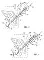
- FIG. 1is a detailed perspective view of an apparatus for passing suture according to various teachings
- FIG. 2is a detailed cross-sectional view of the apparatus for passing suture of FIG. 1 , taken along line 2 - 2 of FIG. 1 , illustrating a various teaching of the apparatus for passing a suture of FIG. 1 ;
- FIG. 3is a perspective exploded view of the apparatus for passing suture of FIG. 1 ;
- FIG. 4is a cross-sectional view of the apparatus for passing suture of FIG. 1 , taken along line 4 - 4 of FIG. 2 ;
- FIG. 5is an alternative cross-sectional view of the apparatus for passing suture of FIG. 1 , taken along line 4 - 4 of FIG. 2 ;
- FIG. 6is an environmental view of a procedure employed to begin the passing of suture into a selected portion of the anatomy according to various teachings
- FIG. 7is an environmental view of the apparatus passing suture into the portion of the anatomy
- FIG. 8is an environmental view of a procedure employed to secure the suture within the anatomy according to various teachings
- FIG. 9is an environmental view of an alternative handle for use with the apparatus for passing suture of FIG. 1 ;
- FIG. 10is an environmental view of a procedure employed to remove the apparatus from the suture after passing the suture into the portion of the anatomy according to various teachings.
- the suture passer assembly 10can include a member 12 and a suture advancement mechanism 14 disposed in a housing or handle 16 .
- the housing 16can define an aperture 15 for receipt of flexible member, such as a suture 18 therein, and an opening 17 to enable the advancement of the suture 18 into the anatomy.
- the suture passer assembly 10can be employed to pass the suture 18 through a portion of the anatomy, such as a section of tissue 20 , as best shown in FIG. 7 .
- the member 12can include a suture receiving portion 22 and a tube defining a throughbore which can also be referred to as a cannula 24 .
- the suture receiving portion 22can define a hollow tubular shape with an interior surface 26 and an exterior surface 28 .
- the suture receiving portion 22may be composed of any appropriate material, such as a metal, metal alloy or a polymeric material.
- the interior surface 26 and exterior surface 28can each have a selected texture, such as smooth.
- the suture receiving portion 22can have a first end 30 and a second end 32 .
- the first end 30 of the suture receiving portion 22can receive the suture 18 and can include an opening 31 for receipt of the suture advancement mechanism 14 therein.
- the second end 32can be covered and may have an opening 34 .
- the opening 34can be configured to engage the cannula 24 and to enable the suture 18 to pass therethrough.
- the opening 34could either include a large diameter adjacent to the suture advancement mechanism 14 for receipt of the suture 18 ( FIG. 4 ) or, in the alternative, can include a small diameter adjacent to the suture advancement mechanism 14 for receipt of the suture 18 .
- the suture receiving portion 22can be the same as or included with the handle 16 .
- the handle 16 and the suture receiving portion 22can be one piece or multiple pieces.
- the cannula 24can be coupled to the suture receiving portion 22 through any appropriate technique such as molding or through a mechanical fastener (not shown).
- the cannula 24can be composed of any appropriate material, such as a bio-compatible metallic material, such as titanium, titanium alloy, stainless steel, cobalt-chromium-molybedenum alloy, but any other bio-compatible material, such as a polymeric material, could be employed.
- the cannula 24can define an interior channel 35 adapted to receive the suture 18 from the suture receiving portion 22 .
- the cannula 24can have a width W which corresponds to a width W 2 of the suture 18 .
- the width Wmay either be slightly larger than the width W 2 (as shown in FIG. 1 ) or may be substantially larger than the width W 2 depending upon the suture 18 employed (as shown in FIG. 2 ) as will be discussed in greater detail below.
- the cannula 24can also include a first end 36 and a second end 38 .
- the first end 36may form a tip 40 .
- the tip 40can be generally formed on the first end 36 , but the tip 40 could also be coupled to the first end 36 through a secondary process, such as through a mechanical fastener or welding.
- the tip 40can be in any desired configuration, such as cylindrical, arcuate, pigtail or corkscrew (not specifically shown). Generally, the tip 40 has a sharp edge 42 for piercing the tissue 20 ( FIG. 6 ).
- the second end 38 of the cannula 24can include an opening 44 for receipt of the suture 18 therein. It will be understood, however, that although the cannula 24 is described as being separate from the suture receiving portion 22 , it could be integrally formed with the suture receiving portion 22 if desired.
- the suture advancement mechanism 14can include a suture driving mechanism, such as a belt 46 , which can translate about at least one or a plurality of members, such as axles, wheels or posts 48 .
- a beltis described and used herein, it will be understood that the belt 46 could be any member capable of contacting the suture over a long length.
- the belt 46can be disposed adjacent to the second end 32 of the suture receiving portion 22 of the member 12 , or within the second end 32 of the suture receiving portion 22 .
- the belt 46can further include a first surface 54 and a second surface 56 adapted to translate about the posts 48 .
- the first surface 54can be generally configured to contact the suture 18 .
- the first surface 54can contact the suture 18 over a selected distance D, which can be equivalent to a length L of the belt 46 .
- the distance Dcan be any appropriate length, such as about 1 mm to 50 mm. Since the belt 46 contacts the suture 18 over the distance D, the belt 46 can keep the suture 18 properly aligned with the cannula 24 .
- the belt 46contacts the suture 18 over a length to assist in aligning the suture 18 as it moves into the cannula 24 .
- the suture 18thus even if flexible, can be efficiently moved into the cannula.
- the first surface 54can also include at least one or a plurality of grooves 58 (as shown in phantom) to contact the suture 18 , or the first surface 54 could be generally smooth. If the first surface 54 includes a plurality of grooves 58 , the first surface 54 can contact the suture 18 at a plurality of discrete surfaces 54 ′ defined by the grooves 58 to advance the suture 18 . If the first surface 54 is generally smooth, the first surface 54 can contact the suture 18 along the selected distance D to advance the suture.
- the first surface 54can be contacted by a power source, such as a finger 106 ( FIG. 7 ), motor, or other mechanism capable of translating the belt 46 .
- the power sourcecan contact a side of the belt 46 opposite the suture 18 to advance the suture 18 .
- the power sourcecan apply a force F in a first direction to translate the belt 46 in a generally clockwise direction to advance the suture 18 into the second end 32 of the member 12 (as best shown in FIG. 7 ).
- a slider 62can be disposed in the opening 17 of the housing 16 . The slider 62 could then be used to contact the first surface 54 of the belt 46 to advance the suture 18 .
- the second surface 56 of the belt 46can also be generally smooth, but can include at least one or a plurality of grooves 58 ′ as shown in phantom.
- the second surface 56can be configured to translate about the posts 48 .
- the posts 48can be fixed to and/or retained in the housing 16 adjacent to the second end 32 of the suture receiving portion 22 , or the posts 48 could be rotatably coupled to the housing 16 (as indicated by the rotational arrow in phantom in FIG. 1 ).
- the posts 48 and belt 46could be molded on a carrier (not shown), and the carrier could be disposed in the housing 16 and in communication with the second end 32 of the suture receiving portion 22 .
- One of the posts 48can be disposed at the first end 50 of the belt 46 and a second one of the posts 48 can be disposed at the second end 52 of the belt 46 , as shown, however, the posts 48 could be disposed at any location along the belt 46 . Also, more than two of the posts 48 could be provided. In addition, additional posts 48 could be retained within the belt 46 but not coupled to the housing 16 to increase the force on the suture 18 to assist in advancing the suture 18 and in gripping the suture 18 during the advancement of the suture 18 (as shown in phantom in FIG. 3 ). Alternatively, as also shown in phantom in FIG.
- posts 48 ′could be sized so as to “float” within the belt 46 to provide additional force on the suture 18 to assist in the advancement of the suture 18 .
- additional posts 48could be rotatably coupled to and/or retained in the housing 16 to assist in raising the belt 46 out of the handle 16 to improve the ease of operation of the suture advancement mechanism 14 (as shown in FIG. 9 ).
- the posts 48 , 48 ′may be composed of any suitable material, such as a polymeric material, but metals or metal alloys could also be employed.
- the suture 18can be any appropriate suture, such as a resorbable suture or a non-resorbable suture.
- the suture 18can be a non-resorbable suture for use in arthroscopic surgical applications, such as a FiberWire suture or Tevdek suture from Arthrex, in Naples, Fla. If a resorbable or non-resorbable suture 18 is used, then the width W of the cannula 24 can be slightly larger than the width W 2 of the suture 18 to prevent bunching of the suture 18 within the cannula 24 during the advancement of the suture 18 ( FIG. 2 ).
- the suture 18can be a reinforced suture 18 with a stiff end 64 (as shown in phantom in FIG. 1 ). If the suture 18 includes the stiff end 64 , then the width W of the member 12 can be any desired size greater than the width W 2 of the suture 18 , as the stiff end 64 can prevent the suture 18 from bunching in the member 12 during the advancement of the suture 18 ( FIG. 1 ).
- the suture passer assembly 10can be used to secure the suture 18 to tissue 20 in a portion of anatomy 100 .
- an incision 102can be made into a selected portion of the skin 104 of a patient to provide access to the tissue 20 .
- the size of the incision 102can be any appropriate size, such as 1 cm to 50 cm, and can include 1 cm to 10 cm.
- the suture passer assembly 10can be inserted through the tissue 20 by using the tip 40 of the cannula 24 to pierce the tissue 20 .
- the power source 60such as a finger 106
- the belt 46can be applied to the belt 46 to begin translating the belt 46 , as shown in FIG. 7 .
- a grasper 108can be inserted into the anatomy 100 through the incision 102 , or any other incision.
- the grasper 108can be of the type manufactured by Arthrotek, of Warsaw, Ind., and can generally include a pair of mating arms which can securely hold an end 110 of the suture 18 which extends beyond the cannula 24 .
- the mating armscan be secured to a small amount of suture 18 , and do not require a large amount of suture 18 in order to firmly hold onto the suture 18 .
- the member 12can be removed from the tissue 20 , as best shown in FIG. 10 .
- the operatorcan use the grasper 108 to hold the end 110 of the suture 18 taught as the member 12 is withdrawn from the tissue 20 . It will be understood that only a small portion of the suture need be advanced to be grasped.
- the suture 18can pass through the member 12 and the belt 46 , leaving the suture 18 within the tissue 20 . With the suture 18 remaining disposed in the tissue 20 , the operator can then use the suture 18 as necessary to secure the tissue 20 to the anatomy 100 (not specifically shown) according to various methods as is known in the art.
- the suture passer assembly 10can provide an efficient mechanism and method of inserting the suture 18 into a portion of the anatomy 100 without requiring a large incision 102 . Further, the suture passer assembly 10 provides for smooth advancement of the suture 18 via use of the suture advancement mechanism 14 . The use of the belt 46 also provides quick and easy advancement of the suture 18 .
Landscapes
- Health & Medical Sciences (AREA)
- Life Sciences & Earth Sciences (AREA)
- Surgery (AREA)
- Heart & Thoracic Surgery (AREA)
- Engineering & Computer Science (AREA)
- Biomedical Technology (AREA)
- Nuclear Medicine, Radiotherapy & Molecular Imaging (AREA)
- Medical Informatics (AREA)
- Molecular Biology (AREA)
- Animal Behavior & Ethology (AREA)
- General Health & Medical Sciences (AREA)
- Public Health (AREA)
- Veterinary Medicine (AREA)
- Surgical Instruments (AREA)
Abstract
Description
Claims (8)
Priority Applications (1)
| Application Number | Priority Date | Filing Date | Title |
|---|---|---|---|
| US11/346,540US8696688B2 (en) | 2006-02-02 | 2006-02-02 | Method and apparatus for passing a flexible strand |
Applications Claiming Priority (1)
| Application Number | Priority Date | Filing Date | Title |
|---|---|---|---|
| US11/346,540US8696688B2 (en) | 2006-02-02 | 2006-02-02 | Method and apparatus for passing a flexible strand |
Publications (2)
| Publication Number | Publication Date |
|---|---|
| US20070179510A1 US20070179510A1 (en) | 2007-08-02 |
| US8696688B2true US8696688B2 (en) | 2014-04-15 |
Family
ID=38323053
Family Applications (1)
| Application Number | Title | Priority Date | Filing Date |
|---|---|---|---|
| US11/346,540Expired - Fee RelatedUS8696688B2 (en) | 2006-02-02 | 2006-02-02 | Method and apparatus for passing a flexible strand |
Country Status (1)
| Country | Link |
|---|---|
| US (1) | US8696688B2 (en) |
Cited By (8)
| Publication number | Priority date | Publication date | Assignee | Title |
|---|---|---|---|---|
| US9089321B2 (en) | 2012-10-15 | 2015-07-28 | Biomet Sports Medicine, Llc | Wheeled suture passer |
| US9962174B2 (en) | 2015-07-17 | 2018-05-08 | Kator, Llc | Transosseous method |
| US10143462B2 (en) | 2015-08-04 | 2018-12-04 | Kator, Llc | Transosseous suture anchor method |
| US10154868B2 (en) | 2015-07-17 | 2018-12-18 | Kator, Llc | Transosseous method |
| US11457912B2 (en) | 2016-06-02 | 2022-10-04 | Parcus Medical, Llc | Suture tool and method of use |
| US11504140B2 (en) | 2015-07-17 | 2022-11-22 | Crossroads Extremity Systems, Llc | Transosseous guide and method |
| US20240293117A1 (en)* | 2016-05-05 | 2024-09-05 | Teleflex Life Sciences Llc | Releasable elongated assembly |
| US12383253B2 (en) | 2015-08-04 | 2025-08-12 | Crossroads Extremity Systems, Llc | Suture anchor |
Families Citing this family (21)
| Publication number | Priority date | Publication date | Assignee | Title |
|---|---|---|---|---|
| US10743862B1 (en) | 2006-05-04 | 2020-08-18 | Alfredo Alvarado | Laparoscopic suturing device and methods of use |
| JP5010178B2 (en)* | 2006-05-30 | 2012-08-29 | 昌貴 鮒田 | Medical instruments |
| US7763039B2 (en)* | 2006-06-09 | 2010-07-27 | Ethicon Endo-Surgery, Inc. | Articulating blunt dissector/gastric band application device |
| US8888795B2 (en)* | 2007-09-07 | 2014-11-18 | Boston Scientific Scimed, Inc. | Suture passer |
| WO2009039513A1 (en)* | 2007-09-20 | 2009-03-26 | Pivot Medical, Inc. | Method and apparatus for re-attaching the labrum of a hip joint |
| DE102007052195A1 (en)* | 2007-10-24 | 2009-04-30 | Karl Storz Gmbh & Co. Kg | Device for moving a suture of a surgical suture instrument |
| CA2702952C (en) | 2007-10-27 | 2017-01-03 | Parcus Medical, Llc | Suture anchor |
| CA2751735C (en) | 2009-02-17 | 2016-11-08 | T.A.G. Medical Devices - Agriculture Cooperative Ltd. | Medical implement for manipulating sutures particularly useful in arthroscopic surgery |
| US9155534B2 (en) | 2009-02-17 | 2015-10-13 | Depuy Mitek Inc. | Side-loaded medical implement particularly useful in arthroscopic surgery |
| EP3150130B1 (en) | 2010-10-13 | 2019-07-03 | Synthes GmbH | Apparatus for guiding a suture thread |
| US9237887B2 (en) | 2011-05-19 | 2016-01-19 | Biomet Sports Medicine, Llc | Tissue engaging member |
| US20130123809A1 (en) | 2011-11-11 | 2013-05-16 | VentureMD Innovations, LLC | Transosseous attachment instruments |
| US10548585B2 (en) | 2011-11-16 | 2020-02-04 | VentureMD Innovations, LLC | Soft tissue attachment |
| US10675014B2 (en) | 2011-11-16 | 2020-06-09 | Crossroads Extremity Systems, Llc | Knotless soft tissue attachment |
| US10136883B2 (en) | 2011-11-16 | 2018-11-27 | VentureMD Innovations, LLC | Method of anchoring a suture |
| US10470756B2 (en) | 2011-11-16 | 2019-11-12 | VentureMD Innovations, LLC | Suture anchor and method |
| WO2014058992A1 (en)* | 2012-10-09 | 2014-04-17 | University Of Cincinnati | Devices and methods for directing a medical fabric into a portion of the body |
| US9687221B2 (en) | 2013-02-13 | 2017-06-27 | Venture MD Innovations, LLC | Method of anchoring a suture |
| WO2015171962A1 (en) | 2014-05-07 | 2015-11-12 | Bart Bracy | Multipart suture |
| EP3410949A4 (en)* | 2016-02-05 | 2019-10-09 | Dura Tap LLC | DEVICES AND METHODS FOR SUTURE PLACEMENT |
| US11517301B2 (en) | 2016-06-02 | 2022-12-06 | Parcus Medical, Llc | Surgical tool and method of use |
Citations (29)
| Publication number | Priority date | Publication date | Assignee | Title |
|---|---|---|---|---|
| US3835854A (en)* | 1970-02-27 | 1974-09-17 | Jewett Ashley Holding Corp | Catheter advancing device with nip rollers |
| US4890615A (en)* | 1987-11-05 | 1990-01-02 | Concept, Inc. | Arthroscopic suturing instrument |
| US4935027A (en)* | 1989-08-21 | 1990-06-19 | Inbae Yoon | Surgical suture instrument with remotely controllable suture material advancement |
| US4957498A (en)* | 1987-11-05 | 1990-09-18 | Concept, Inc. | Suturing instrument |
| US5254126A (en)* | 1992-06-24 | 1993-10-19 | Ethicon, Inc. | Endoscopic suture punch |
| US5290310A (en)* | 1991-10-30 | 1994-03-01 | Howmedica, Inc. | Hemostatic implant introducer |
| US5318541A (en)* | 1993-03-02 | 1994-06-07 | Cordis Corporation | Apparatus for catheter exchange in vascular dilitation |
| US5346498A (en)* | 1991-11-06 | 1994-09-13 | Imagyn Medical, Inc. | Controller for manipulation of instruments within a catheter |
| US5447512A (en)* | 1992-06-23 | 1995-09-05 | Boston Scientific Corporation | Controller for intracorporeal knot tying apparatus |
| US5643292A (en)* | 1995-01-10 | 1997-07-01 | Applied Medical Resources Corporation | Percutaneous suturing device |
| US5690645A (en)* | 1995-06-28 | 1997-11-25 | Cordis Corporation | Device for moving a catheter in a controlled manner |
| US5746753A (en)* | 1996-05-13 | 1998-05-05 | Boston Scientific Corporation | Needle grasping apparatus |
| US5755728A (en)* | 1996-03-07 | 1998-05-26 | Maki; Neil J. | Suture apparatus with loop end portions |
| US5766186A (en)* | 1996-12-03 | 1998-06-16 | Simon Fraser University | Suturing device |
| US5971991A (en)* | 1997-05-07 | 1999-10-26 | Sunderland; Mark | Catheter driver |
| US6022360A (en)* | 1997-08-06 | 2000-02-08 | Ethicon, Inc. | Suture retrograder |
| US6171234B1 (en)* | 1998-09-25 | 2001-01-09 | Scimed Life Systems, Inc. | Imaging gore loading tool |
| US20030015203A1 (en)* | 1995-12-01 | 2003-01-23 | Joshua Makower | Device, system and method for implantation of filaments and particles in the body |
| US20030153948A1 (en) | 2002-02-08 | 2003-08-14 | Morrison David S. | Stiff tipped suture |
| US6629984B1 (en)* | 1998-07-07 | 2003-10-07 | Kwan-Ho Chan | Surgical repair kit and its method of use |
| US20050080476A1 (en)* | 2003-10-09 | 2005-04-14 | Gunderson Richard C. | Medical device delivery system |
| US20050165417A1 (en)* | 2001-11-27 | 2005-07-28 | Michael Sauer | Suturing set for medical use |
| US20050245847A1 (en)* | 2004-04-30 | 2005-11-03 | Cook, Inc. | Wire guide apparatus |
| US20050283171A1 (en)* | 2004-06-18 | 2005-12-22 | Bellafiore Mark A | Hollow suture needle with handle |
| US20060025721A1 (en)* | 2004-07-30 | 2006-02-02 | Niall Duffy | Catheter and guidewire exchange system with improved catheter design |
| US7294135B2 (en)* | 2003-03-20 | 2007-11-13 | Medtronic Vascular, Inc | Control handle for intraluminal devices |
| US7591268B2 (en)* | 1999-08-23 | 2009-09-22 | Conceptus, Inc. | Deployment actuation system for intrafallopian contraception |
| US8221305B2 (en)* | 2004-05-06 | 2012-07-17 | Olympus Corporation | Endoscope treatment tool system |
| US8425465B2 (en)* | 2008-03-25 | 2013-04-23 | Ntn Corporation | Drive device for linear body |
- 2006
- 2006-02-02USUS11/346,540patent/US8696688B2/ennot_activeExpired - Fee Related
Patent Citations (34)
| Publication number | Priority date | Publication date | Assignee | Title |
|---|---|---|---|---|
| US3835854A (en)* | 1970-02-27 | 1974-09-17 | Jewett Ashley Holding Corp | Catheter advancing device with nip rollers |
| US4923461B1 (en)* | 1987-11-05 | 1994-10-18 | Linvatec Corp | Method of arthroscopic suturing of tissue |
| US4890615A (en)* | 1987-11-05 | 1990-01-02 | Concept, Inc. | Arthroscopic suturing instrument |
| US4923461A (en)* | 1987-11-05 | 1990-05-08 | Concept, Inc. | Method of arthroscopic suturing of tissue |
| US4957498A (en)* | 1987-11-05 | 1990-09-18 | Concept, Inc. | Suturing instrument |
| US4890615B1 (en)* | 1987-11-05 | 1993-11-16 | Linvatec Corporation | Arthroscopic suturing instrument |
| US4923461B2 (en)* | 1987-11-05 | 1995-06-20 | Linvatec Corp | Method of arthroscopic suturing |
| US4935027A (en)* | 1989-08-21 | 1990-06-19 | Inbae Yoon | Surgical suture instrument with remotely controllable suture material advancement |
| US5290310A (en)* | 1991-10-30 | 1994-03-01 | Howmedica, Inc. | Hemostatic implant introducer |
| US5346498A (en)* | 1991-11-06 | 1994-09-13 | Imagyn Medical, Inc. | Controller for manipulation of instruments within a catheter |
| US5447512A (en)* | 1992-06-23 | 1995-09-05 | Boston Scientific Corporation | Controller for intracorporeal knot tying apparatus |
| US5254126A (en)* | 1992-06-24 | 1993-10-19 | Ethicon, Inc. | Endoscopic suture punch |
| US5318541A (en)* | 1993-03-02 | 1994-06-07 | Cordis Corporation | Apparatus for catheter exchange in vascular dilitation |
| US5643292A (en)* | 1995-01-10 | 1997-07-01 | Applied Medical Resources Corporation | Percutaneous suturing device |
| US5690645A (en)* | 1995-06-28 | 1997-11-25 | Cordis Corporation | Device for moving a catheter in a controlled manner |
| US20030015203A1 (en)* | 1995-12-01 | 2003-01-23 | Joshua Makower | Device, system and method for implantation of filaments and particles in the body |
| US5755728A (en)* | 1996-03-07 | 1998-05-26 | Maki; Neil J. | Suture apparatus with loop end portions |
| US5746753A (en)* | 1996-05-13 | 1998-05-05 | Boston Scientific Corporation | Needle grasping apparatus |
| US5766186A (en)* | 1996-12-03 | 1998-06-16 | Simon Fraser University | Suturing device |
| US5971991A (en)* | 1997-05-07 | 1999-10-26 | Sunderland; Mark | Catheter driver |
| US6022360A (en)* | 1997-08-06 | 2000-02-08 | Ethicon, Inc. | Suture retrograder |
| US6629984B1 (en)* | 1998-07-07 | 2003-10-07 | Kwan-Ho Chan | Surgical repair kit and its method of use |
| US6171234B1 (en)* | 1998-09-25 | 2001-01-09 | Scimed Life Systems, Inc. | Imaging gore loading tool |
| US7591268B2 (en)* | 1999-08-23 | 2009-09-22 | Conceptus, Inc. | Deployment actuation system for intrafallopian contraception |
| US20050165417A1 (en)* | 2001-11-27 | 2005-07-28 | Michael Sauer | Suturing set for medical use |
| US20030153948A1 (en) | 2002-02-08 | 2003-08-14 | Morrison David S. | Stiff tipped suture |
| US7294135B2 (en)* | 2003-03-20 | 2007-11-13 | Medtronic Vascular, Inc | Control handle for intraluminal devices |
| US20050080476A1 (en)* | 2003-10-09 | 2005-04-14 | Gunderson Richard C. | Medical device delivery system |
| US20050245847A1 (en)* | 2004-04-30 | 2005-11-03 | Cook, Inc. | Wire guide apparatus |
| US8221305B2 (en)* | 2004-05-06 | 2012-07-17 | Olympus Corporation | Endoscope treatment tool system |
| US20050283171A1 (en)* | 2004-06-18 | 2005-12-22 | Bellafiore Mark A | Hollow suture needle with handle |
| US7704262B2 (en)* | 2004-06-18 | 2010-04-27 | Linvatec Corporation | Hollow suture needle with handle |
| US20060025721A1 (en)* | 2004-07-30 | 2006-02-02 | Niall Duffy | Catheter and guidewire exchange system with improved catheter design |
| US8425465B2 (en)* | 2008-03-25 | 2013-04-23 | Ntn Corporation | Drive device for linear body |
Non-Patent Citations (1)
| Title |
|---|
| "SpeedPass Suture Retrievers," copyright 2004 Arthrotek, Inc. |
Cited By (13)
| Publication number | Priority date | Publication date | Assignee | Title |
|---|---|---|---|---|
| US9877716B2 (en) | 2012-10-15 | 2018-01-30 | Biomet Sports Medicine, Llc | Wheeled suture passer |
| US9089321B2 (en) | 2012-10-15 | 2015-07-28 | Biomet Sports Medicine, Llc | Wheeled suture passer |
| US10258401B2 (en) | 2015-07-17 | 2019-04-16 | Kator, Llc | Transosseous guide |
| US9962174B2 (en) | 2015-07-17 | 2018-05-08 | Kator, Llc | Transosseous method |
| US10154868B2 (en) | 2015-07-17 | 2018-12-18 | Kator, Llc | Transosseous method |
| US11504140B2 (en) | 2015-07-17 | 2022-11-22 | Crossroads Extremity Systems, Llc | Transosseous guide and method |
| US10143462B2 (en) | 2015-08-04 | 2018-12-04 | Kator, Llc | Transosseous suture anchor method |
| US10226243B2 (en) | 2015-08-04 | 2019-03-12 | Kator, Llc | Transosseous suture anchor |
| US12383253B2 (en) | 2015-08-04 | 2025-08-12 | Crossroads Extremity Systems, Llc | Suture anchor |
| US20240293117A1 (en)* | 2016-05-05 | 2024-09-05 | Teleflex Life Sciences Llc | Releasable elongated assembly |
| US12402876B2 (en)* | 2016-05-05 | 2025-09-02 | Teleflex Life Sciences Llc | Releasable elongated assembly |
| US11457912B2 (en) | 2016-06-02 | 2022-10-04 | Parcus Medical, Llc | Suture tool and method of use |
| US12274436B2 (en) | 2016-06-02 | 2025-04-15 | Parcus Medical, Llc | Suture tool and method of use |
Also Published As
| Publication number | Publication date |
|---|---|
| US20070179510A1 (en) | 2007-08-02 |
Similar Documents
| Publication | Publication Date | Title |
|---|---|---|
| US8696688B2 (en) | Method and apparatus for passing a flexible strand | |
| US5746216A (en) | Endoscopic multiple sample bioptome with enhanced biting action | |
| JP5010178B2 (en) | Medical instruments | |
| JP4616301B2 (en) | Endoscopic treatment tool | |
| EP1221896B1 (en) | Biopsy jaw assembly | |
| US8709022B2 (en) | Method and apparatus for passing a suture | |
| US4784139A (en) | Needle guide instrument | |
| US20040087978A1 (en) | Surgical fascia closure instrument, guide and method | |
| JP6270847B2 (en) | Suture device | |
| US9301748B2 (en) | Suture apparatus, system and method | |
| CN110545736B (en) | Endovascular surgery system | |
| WO2005102179A1 (en) | Suture cutting device | |
| JP2002523171A (en) | Surgical suturing instruments and other uses | |
| US10660636B2 (en) | Suture apparatus, system and method | |
| US10231730B2 (en) | Suture apparatus, system and method | |
| JPH03139340A (en) | Treating implement for endoscope | |
| JP4132343B2 (en) | Biopsy forceps | |
| US11369367B2 (en) | Suturing device | |
| EP0720441A1 (en) | Multiple biopsy sampling forceps | |
| US20120330339A1 (en) | Tissue cutting device, assembly and method | |
| JPH0956719A (en) | Medical thread needle guide | |
| US20250312061A1 (en) | Arthroscopic Cannula and Insertion Tool | |
| JPH08280700A (en) | Surgical appliance | |
| US20050090839A1 (en) | Apparatus, system and method for the placement and controlled manipulation of threads like in ligatures | |
| EP1512377B1 (en) | Apparatus for manipulation of threads such as ligatures |
Legal Events
| Date | Code | Title | Description |
|---|---|---|---|
| AS | Assignment | Owner name:ARTHROTEK, INC., INDIANA Free format text:ASSIGNMENT OF ASSIGNORS INTEREST;ASSIGNOR:STONE, KEVIN T.;REEL/FRAME:017542/0972 Effective date:20060131 | |
| AS | Assignment | Owner name:BIOMET SPORTS MEDICINE, INC., INDIANA Free format text:CHANGE OF NAME;ASSIGNOR:ARTHROTEK, INC.;REEL/FRAME:019040/0720 Effective date:20061227 Owner name:BIOMET SPORTS MEDICINE, INC.,INDIANA Free format text:CHANGE OF NAME;ASSIGNOR:ARTHROTEK, INC.;REEL/FRAME:019040/0720 Effective date:20061227 | |
| AS | Assignment | Owner name:BANK OF AMERICA, N.A., AS ADMINISTRATIVE AGENT FOR Free format text:SECURITY AGREEMENT;ASSIGNORS:LVB ACQUISITION, INC.;BIOMET, INC.;REEL/FRAME:020362/0001 Effective date:20070925 | |
| AS | Assignment | Owner name:BIOMET SPORTS MEDICINE, LLC, INDIANA Free format text:CHANGE OF NAME;ASSIGNOR:BIOMET SPORTS MEDICINE, INC.;REEL/FRAME:021387/0441 Effective date:20080227 Owner name:BIOMET SPORTS MEDICINE, LLC,INDIANA Free format text:CHANGE OF NAME;ASSIGNOR:BIOMET SPORTS MEDICINE, INC.;REEL/FRAME:021387/0441 Effective date:20080227 | |
| STCF | Information on status: patent grant | Free format text:PATENTED CASE | |
| AS | Assignment | Owner name:LVB ACQUISITION, INC., INDIANA Free format text:RELEASE OF SECURITY INTEREST IN PATENTS RECORDED AT REEL 020362/ FRAME 0001;ASSIGNOR:BANK OF AMERICA, N.A., AS ADMINISTRATIVE AGENT;REEL/FRAME:037155/0133 Effective date:20150624 Owner name:BIOMET, INC., INDIANA Free format text:RELEASE OF SECURITY INTEREST IN PATENTS RECORDED AT REEL 020362/ FRAME 0001;ASSIGNOR:BANK OF AMERICA, N.A., AS ADMINISTRATIVE AGENT;REEL/FRAME:037155/0133 Effective date:20150624 | |
| MAFP | Maintenance fee payment | Free format text:PAYMENT OF MAINTENANCE FEE, 4TH YEAR, LARGE ENTITY (ORIGINAL EVENT CODE: M1551) Year of fee payment:4 | |
| AS | Assignment | Owner name:BIOMET, INC., INDIANA Free format text:ASSIGNMENT OF ASSIGNORS INTEREST;ASSIGNOR:BIOMET U.S. RECONSTRUCTION, LLC;REEL/FRAME:045935/0557 Effective date:20171103 Owner name:BIOMET U.S. RECONSTRUCTION, LLC, INDIANA Free format text:ASSIGNMENT OF ASSIGNORS INTEREST;ASSIGNOR:BIOMET SPORTS MEDICINE, LLC;REEL/FRAME:045935/0497 Effective date:20171103 Owner name:ZB MANUFACTURING, LLC, INDIANA Free format text:ASSIGNMENT OF ASSIGNORS INTEREST;ASSIGNOR:BIOMET, INC.;REEL/FRAME:045935/0570 Effective date:20171103 Owner name:BIOMET MANUFACTURING, LLC, INDIANA Free format text:ASSIGNMENT OF ASSIGNORS INTEREST;ASSIGNOR:ZB MANUFACTURING, LLC;REEL/FRAME:045935/0673 Effective date:20171103 | |
| FEPP | Fee payment procedure | Free format text:MAINTENANCE FEE REMINDER MAILED (ORIGINAL EVENT CODE: REM.); ENTITY STATUS OF PATENT OWNER: LARGE ENTITY | |
| LAPS | Lapse for failure to pay maintenance fees | Free format text:PATENT EXPIRED FOR FAILURE TO PAY MAINTENANCE FEES (ORIGINAL EVENT CODE: EXP.); ENTITY STATUS OF PATENT OWNER: LARGE ENTITY | |
| STCH | Information on status: patent discontinuation | Free format text:PATENT EXPIRED DUE TO NONPAYMENT OF MAINTENANCE FEES UNDER 37 CFR 1.362 | |
| FP | Lapsed due to failure to pay maintenance fee | Effective date:20220415 |