US8696597B2 - Diagnostic meter - Google Patents
Diagnostic meterDownload PDFInfo
- Publication number
- US8696597B2 US8696597B2US11/395,266US39526606AUS8696597B2US 8696597 B2US8696597 B2US 8696597B2US 39526606 AUS39526606 AUS 39526606AUS 8696597 B2US8696597 B2US 8696597B2
- Authority
- US
- United States
- Prior art keywords
- meter
- diagnostic
- test
- partner device
- media
- Prior art date
- Legal status (The legal status is an assumption and is not a legal conclusion. Google has not performed a legal analysis and makes no representation as to the accuracy of the status listed.)
- Active, expires
Links
Images


Classifications
- A—HUMAN NECESSITIES
- A61—MEDICAL OR VETERINARY SCIENCE; HYGIENE
- A61B—DIAGNOSIS; SURGERY; IDENTIFICATION
- A61B5/00—Measuring for diagnostic purposes; Identification of persons
- A61B5/0002—Remote monitoring of patients using telemetry, e.g. transmission of vital signals via a communication network
- A—HUMAN NECESSITIES
- A61—MEDICAL OR VETERINARY SCIENCE; HYGIENE
- A61B—DIAGNOSIS; SURGERY; IDENTIFICATION
- A61B5/00—Measuring for diagnostic purposes; Identification of persons
- A61B5/145—Measuring characteristics of blood in vivo, e.g. gas concentration or pH-value ; Measuring characteristics of body fluids or tissues, e.g. interstitial fluid or cerebral tissue
- A61B5/14532—Measuring characteristics of blood in vivo, e.g. gas concentration or pH-value ; Measuring characteristics of body fluids or tissues, e.g. interstitial fluid or cerebral tissue for measuring glucose, e.g. by tissue impedance measurement
- G—PHYSICS
- G01—MEASURING; TESTING
- G01N—INVESTIGATING OR ANALYSING MATERIALS BY DETERMINING THEIR CHEMICAL OR PHYSICAL PROPERTIES
- G01N33/00—Investigating or analysing materials by specific methods not covered by groups G01N1/00 - G01N31/00
- G01N33/48—Biological material, e.g. blood, urine; Haemocytometers
- G01N33/483—Physical analysis of biological material
- G01N33/487—Physical analysis of biological material of liquid biological material
- G01N33/4875—Details of handling test elements, e.g. dispensing or storage, not specific to a particular test method
- G01N33/48778—Containers specially adapted therefor, e.g. for dry storage
- G—PHYSICS
- G01—MEASURING; TESTING
- G01N—INVESTIGATING OR ANALYSING MATERIALS BY DETERMINING THEIR CHEMICAL OR PHYSICAL PROPERTIES
- G01N33/00—Investigating or analysing materials by specific methods not covered by groups G01N1/00 - G01N31/00
- G01N33/48—Biological material, e.g. blood, urine; Haemocytometers
- G01N33/483—Physical analysis of biological material
- G01N33/487—Physical analysis of biological material of liquid biological material
- G01N33/48785—Electrical and electronic details of measuring devices for physical analysis of liquid biological material not specific to a particular test method, e.g. user interface or power supply
- G01N33/48792—Data management, e.g. communication with processing unit
- G—PHYSICS
- G16—INFORMATION AND COMMUNICATION TECHNOLOGY [ICT] SPECIALLY ADAPTED FOR SPECIFIC APPLICATION FIELDS
- G16H—HEALTHCARE INFORMATICS, i.e. INFORMATION AND COMMUNICATION TECHNOLOGY [ICT] SPECIALLY ADAPTED FOR THE HANDLING OR PROCESSING OF MEDICAL OR HEALTHCARE DATA
- G16H10/00—ICT specially adapted for the handling or processing of patient-related medical or healthcare data
- G16H10/40—ICT specially adapted for the handling or processing of patient-related medical or healthcare data for data related to laboratory analysis, e.g. patient specimen analysis
- A—HUMAN NECESSITIES
- A61—MEDICAL OR VETERINARY SCIENCE; HYGIENE
- A61B—DIAGNOSIS; SURGERY; IDENTIFICATION
- A61B2560/00—Constructional details of operational features of apparatus; Accessories for medical measuring apparatus
- A61B2560/02—Operational features
- A61B2560/0242—Operational features adapted to measure environmental factors, e.g. temperature, pollution
- A—HUMAN NECESSITIES
- A61—MEDICAL OR VETERINARY SCIENCE; HYGIENE
- A61B—DIAGNOSIS; SURGERY; IDENTIFICATION
- A61B2560/00—Constructional details of operational features of apparatus; Accessories for medical measuring apparatus
- A61B2560/04—Constructional details of apparatus
- A61B2560/0456—Apparatus provided with a docking unit
- A—HUMAN NECESSITIES
- A61—MEDICAL OR VETERINARY SCIENCE; HYGIENE
- A61B—DIAGNOSIS; SURGERY; IDENTIFICATION
- A61B2562/00—Details of sensors; Constructional details of sensor housings or probes; Accessories for sensors
- A61B2562/02—Details of sensors specially adapted for in-vivo measurements
- A61B2562/0295—Strip shaped analyte sensors for apparatus classified in A61B5/145 or A61B5/157
- G—PHYSICS
- G16—INFORMATION AND COMMUNICATION TECHNOLOGY [ICT] SPECIALLY ADAPTED FOR SPECIFIC APPLICATION FIELDS
- G16H—HEALTHCARE INFORMATICS, i.e. INFORMATION AND COMMUNICATION TECHNOLOGY [ICT] SPECIALLY ADAPTED FOR THE HANDLING OR PROCESSING OF MEDICAL OR HEALTHCARE DATA
- G16H40/00—ICT specially adapted for the management or administration of healthcare resources or facilities; ICT specially adapted for the management or operation of medical equipment or devices
- G16H40/60—ICT specially adapted for the management or administration of healthcare resources or facilities; ICT specially adapted for the management or operation of medical equipment or devices for the operation of medical equipment or devices
- G16H40/63—ICT specially adapted for the management or administration of healthcare resources or facilities; ICT specially adapted for the management or operation of medical equipment or devices for the operation of medical equipment or devices for local operation
Definitions
- the present inventionrelates to the field of diagnostic testing and, more particularly, to diagnostic testing systems using electronic meters and digital communication.
- the diagnostic testmay be a qualitative or quantitative test to determine the presence, concentration or amount of one or more analytes in a sample.
- the analytemay be a medically significant analyte—e.g., glucose, ketones, cholesterol, triglycerides, human choriogonadotropin (HCG), hemoglobin A1C, fructosamine, carbohydrates, tumor markers, lead, anti-epilepsy drugs, bilirubin, liver function markers, toxins or their metabolites, controlled substances, blood coagulation factors (PT, ATPP), etc.—contained in a biological sample—e.g., blood, urine, tissue, saliva, etc.
- a biological samplee.g., blood, urine, tissue, saliva, etc.
- Diagnostic test meterscan also be used to monitor analytes or chemical parameters in non-medical samples such as water, food products, soil, sewage, sand, air, or any other suitable sample.
- Diagnostic testing systemscan include test media (e.g., a test strip, tab, disc, etc.) configured to react to a specific analyte or analytes in a sample, and a separate electronic device configured to interface with the test media, conduct the diagnostic test, and indicate the results of the diagnostic test to the user.
- test mediae.g., a test strip, tab, disc, etc.
- separate electronic deviceconfigured to interface with the test media, conduct the diagnostic test, and indicate the results of the diagnostic test to the user.
- test mediae.g., a test strip from a container
- a test samplemay require the use of a sampling device (e.g., a lancet).
- a sampling devicee.g., a lancet
- the userapplies the sample to the test media either before or after inserting the test media into the meter interface.
- the meterthen performs a diagnostic test on the sample and indicates the test result to the user, e.g., using a visual display.
- diagnostic metershave an onboard memory for storing results over a period of time so that a user can record test results and, with the help of a health care professional, evaluate trends in the test data.
- Some systems known in the artalso allow uploading test result data to a personal computer using an appropriate data cable. The user may then use software pre-installed on the personal computer to display and analyze the data, or to transmit the test results to a physician so that an assessment of the patient's condition can be made.
- the pre-installed softwareincludes any drivers necessary to allow the diagnostic meter, which is a specialized device, to interface with the PC.
- the meter's userBecause it is usually inconvenient for the user to carry a data cable, along with the diagnostic meter hardware while away from home, the meter's user will usually use the meter's onboard memory to store test results until the user can upload the results to a PC. Since it may be somewhat inconvenient and tedious to connect the meter to the computer via the data cable, a period of days or even weeks can elapse before data is transferred to the computer. This delay can translate to missed opportunities to diagnose important trends in the data.
- test media cartridgese.g., a disk
- the lancet setincludes both a lancing device body and a supply of lancet points, where a new lancet point is used for each diagnostic test.
- test media from different manufacturers or media from different manufacturing lotsmay respond differently to the presence or concentration of analyte in a sample.
- the electronic metermay be calibrated with one or more calibration parameters that correlate the signal response from a particular brand or lot of test media to a standardized reference. Without such calibration, the results reported by the meter may not accurately represent the amount of analyte in the sample.
- the usermay be required, in addition to the above steps, to manually enter an appropriate calibration code number, from which the meter can access the appropriate calibration information stored in the meter's memory.
- each test media containermay be provided with an associated code chip, e.g. a ROM, on which the calibration data is stored electronically.
- the usermay provide the calibration data to the meter by inserting the code chip into a corresponding port on the meter.
- an integrated diagnostic testing systemincluding a remote diagnostic meter for performing a diagnostic test on a sample applied to test media, the meter including a housing, a mass storage device, and a data interface device, wherein the housing contains a test media interface.
- the diagnostic metermay optionally include a display for displaying the test results.
- the meterin order to provide a meter that is small, portable and convenient to carry, the meter may not include a display for displaying the test results.
- the metercan be wirelessly connected to a partner device, such as a MP3 player, cell phone, digital camera, personal digital assistant, or other similar wireless information device, in order to display the test results on the partner device's high quality screen.
- a partner devicesuch as a MP3 player, cell phone, digital camera, personal digital assistant, or other similar wireless information device
- the illustrative embodimentsfurther provide mechanisms for coupling a remote diagnostic meter and a computer for communication, without the requirement that the user perform any special set-up steps.
- Datacan be directly downloaded from the remote meter and stored onto a personal computer or stored in the meter, for example, in flash memory of a USB data connector.
- the illustrative embodiments described hereinprovide a USB data connector of the diagnostic meter wirelessly connected to the computer.
- the wireless communications devicesmay be RF, IR, BlueTooth®, Near Field Communication (NFC), or other similar devices consistent with the principles of the present invention.
- Illustrative embodiments of the present inventionalternatively provide a remote meter pre-paired with a transceiver dock or a cradle, in the event a partner device is not equipped with wireless technology.
- the dockcan be affixed to a partner device, such as a MP3 player, and communicate with the partner device via a hardwired connection.
- Wired communications between the dock and the partner devicein conjunction with wireless communications between the dock and the remote meter, provide a means for a non-wireless partner device to benefit from the same wireless functionality as if the partner device was, in fact, wireless itself.
- the illustrative embodimentsfurther provide a diagnostic meter calibrated for use with a particular lot of test media by coding with appropriate calibration parameters.
- the metermay be configured to read a calibration code on the diagnostic test strip.
- the metermay only be provided with strips corresponding to a preprogrammed set of calibration data for use with the meter.
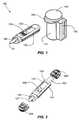
- FIG. 1is a perspective view of a first illustrative embodiment of an integrated remote diagnostic meter assembly consistent with the present invention.
- FIG. 2illustrates a perspective view of a remote diagnostic meter with an integrated data connector consistent with the present invention.
- FIGS. 3A and 3Bare perspective views of a second illustrative embodiment of an integrated remote diagnostic meter assembly consistent with the present invention.
- FIG. 4is a perspective view of a meter interfacing with a computer.
- FIG. 5illustrates a perspective view of a data connector portion of a meter consistent with the invention.
- FIG. 6is a perspective view of an illustrative integrated remote diagnostic meter assembly wirelessly communicating with a computer.
- FIGS. 7A , 7 B, and 7 Care perspective views of a remote diagnostic meter pre-paired with a docking transceiver.
- FIG. 8illustrates an exemplary block diagram of an electronic diagnostic meter consistent with the present invention.
- FIG. 9is a cross-sectional view of a further illustrative embodiment of an integrated remote diagnostic system consistent with the present invention.
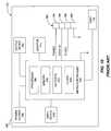
- FIG. 10is an exemplary block diagram of a prior art, general purpose computer usable with the present invention.
- FIG. 11is a flow chart illustrating a method of storing and auto-executing program files from a remote diagnostic meter to a personal computer.
- FIG. 12is a perspective view of an illustrative integrated remote diagnostic meter assembly shaped to close an opening of a container.
- FIGS. 13A and 13Bare perspective views of a remote diagnostic meter pre-paired with a cradle.
- FIG. 1is an integrated system 100 for conducting a diagnostic test in accordance with an exemplary embodiment of the present invention.
- Exemplary integrated system 100can include a container 110 with a closure 140 for containing test media, such as test strips 120 , and a stand-alone remote meter 130 for performing a diagnostic test using the test strips 120 contained in container 110 , including a display 133 for displaying the test results.
- remote meter 130may be provided without a display 133 (not shown) in order to keep manufacturing costs at a minimum and the meter device small and compact.
- Meter 130can be wirelessly connected to a partner device, such a MP3 player, cell phone, digital camera, personal digital assistant, or other similar wireless information device, in order to display the test results on the partner device's high quality screen.
- partner devicesuch as a MP3 player, cell phone, digital camera, personal digital assistant, or other similar wireless information device
- meter 130By off-loading the bulk of the diagnostic system, i.e. display, result memory, user interface, etc., to a multi-purpose partner device with these built-in capabilities, the meter 130 can be reduced in size to only include the essentials, i.e. a strip connector, data acquisition system, and wireless communication module. Reduced size and wireless connectivity makes the remote meter 130 highly portable, while providing a large remote display and remote data management.
- container 110 and closure 140are formed of polypropylene using an injection molding process, but other materials known in the art can be used.
- Container 110 and closure 140can be configured to prevent the infiltration of light, liquid, vapor, and/or air into the container 110 to prevent contamination or degradation of the test media. Where the test media may be toxic or may present a choking hazard to children, closure 140 may optionally be configured to be locked or child-resistant, as is known in the art.
- the container 110is shown as a right circular cylinder, however, the container 110 and its opening may be made in a number of other shapes.
- the container 110can also be customized with graphical designs appealing to individual users, or the corporate logos of co-branding partners, etc.
- remote meter 130may have an exterior shape similar to that of the container 110 so that the integrated system 100 can attach to and engage with an opening of the container 110 in order to selectively close the opening thereof.
- the remote meter 130further includes a data connector 602 adapted to interface with a computer 112 , as further described below.
- attach tomay be used to signify affiliated with, associated with, affixed with/to, connected with/to, coupled with/to, fastened with/to, fixed with/to, secured with/to, etc.
- the container 110 and the meter 130may be configured in different shapes without departing from the scope of the present invention.
- Exemplary meter housing and container embodimentsare described in commonly-assigned co-pending U.S. patent application Ser. No. 10/857,917, filed Jun. 2, 2004, and U.S. patent application Ser. No. 11/254,881, filed Oct. 21, 2005, both of which are incorporated by reference herein in their entirety.
- closure 140is provided with a protrusion 143 which extends beyond the side of container 110 , to sufficiently aid the user in opening and closing the container 110 , e.g., by pushing upward with the thumb against the protrusion 143 .
- the container 110 and closure 140may be integrally connected by a hinge, e.g., as shown in U.S. Pat. No. 5,723,085, entitled “PROCESS AND APPARATUS FOR MAKING A LEAK PROOF CAP AND BODY ASSEMBLY,” which is incorporated by reference herein in its entirety.
- container 110 and closure 140may be integrally connected by a lanyard or other flexible connector, such as a flexible plastic band or wire, etc. (not shown).
- one end of the connectormay be connected to a ring (not shown) that is sized to fit over container 110 .
- the ringmay be configured to loosely and frictionally engage container 110 .
- the ringmay be affixed to the container 110 , e.g., by welding, gluing, etc.
- meter 130may employ any variety of techniques.
- the diagnostic testemploys an electrochemical technique (e.g., coulometry, amperometry, potentiometry, etc.).
- electrochemical techniquese.g., coulometry, amperometry, potentiometry, etc.
- Exemplary electrochemical systemsare described in prior U.S. Pat. No. 6,743,635, issued Jun. 1, 2004, and U.S. Pat. No. 6,946,299, issued Sep. 20, 2005, both entitled “SYSTEM AND METHOD FOR BLOOD GLUCOSE TESTING” and commonly assigned with the instant application, both of which are incorporated by reference herein in their entirety.
- meter 130may employ a photometric technique (e.g., reflection, transmission, scattering, absorption, fluorescence, electro-chemiluminescence, etc.) to determine the amount of glucose in the sample.
- a photometric techniquee.g., reflection, transmission, scattering, absorption, fluorescence, electro-chemiluminescence, etc.
- Exemplary photometric systemsare described in U.S. Pat. Nos. 6,201,607, 6,284,550 and 6,541,266, each commonly-assigned with the instant application, which are incorporated by reference herein in their entirety.
- Electrochemical systemsare currently popular because, among other reasons, they require a smaller blood sample (on the order of 1 ⁇ L or less) than the photometric techniques (on the order of 1 ⁇ L or greater), and electrochemical meters typically require less power and are smaller than their photometric counterparts.
- Integrated system 100will be illustrated with reference to a diagnostic test to determine the concentration of blood glucose using an electrochemical technique, with the understanding that the principles of the present invention are equally applicable to other types of diagnostic tests and techniques, such as those mentioned above.
- the present inventionhas been illustrated as utilizing test media in the form of test strips 120 , exemplary embodiments of the present invention are not limited to a particular type of media, and those of skill in the art will recognize that the principles of the present invention are equally applicable to diagnostic testing systems which employ test media in other forms, e.g., tabs, discs, etc.
- meter 130may be attached to test strip container 110 via a holster-type receptacle 132 formed on the side of the test strip container 110 . Additionally, a strip ejector mechanism 134 can be provided on the meter 130 to dispose of the strip 120 without touching.
- integrated meter 130includes a data connector 602 adapted to interface with a computer, as further illustrated in FIG. 4 .
- Protective covers 600may be attached to the ends of meter 130 to protect the sample chamber 121 and USB data connector 602 from contamination, static electricity and damage.
- the covers 600can vary in size, shape, color or texture to provide for tactile and visual discrimination.
- FIGS. 3A and 3BAlternative embodiments provide a meter 130 attached to a lancing device 360 that can be used together or separately as illustrated in FIGS. 3A and 3B .
- the integrated meter-lancing devicecan also be attached to a vial, as shown in FIG. 1 , by a holster or other known means or attachment.
- Further details of exemplary lancing device 360are shown in prior application Ser. No. 10/757,776, entitled “LANCING DEVICE,” filed Jan. 15, 2004, commonly-assigned with the instant application, which is incorporated by reference herein in its entirety.
- the present inventionis not limited to any particular sampling device, and one of skill in the art will recognize that other sampling devices can be incorporated in a manner similar to the exemplary lancing device described above.
- computer hardware, device drivers, and the operating systemmust all be in sync to allow installation without user intervention.
- Windows®provides plug-and-play functionality
- the operating systemcannot automatically configure and start the device.
- prior art diagnostic metersrequire the user to first download and install device drivers before connecting the meter to the computer.
- the operating systemAfter a computer detects the connection of a new device, the operating system checks which hardware resources the device needs (such as interrupts, memory ranges, I/O ranges, and DMA channels) and assigns those resources. These requirements are derived from a hardware identification number provided by the device. The operating system then checks the availability of a driver that matches the hardware identification number of the device. The operating system can also choose among several drivers, should more than one be identified.
- hardware resources the device needssuch as interrupts, memory ranges, I/O ranges, and DMA channels
- the deviceIf the device is not automatically installed by the operating system, the procedure becomes increasingly complicated as the operating system will request from the user information about the device and where to find drivers. For non-standard devices, such as diagnostics meters, specialized drivers are required. Also, for networked computers under administrative control, such as those most frequently encountered in the workplace and those generally available for public access, restricted privileges are required for a user to install or configure a specialized, non-standard device.
- the present inventionprovides mechanisms for coupling a remote diagnostic meter 130 and a computer 112 for communication, as shown in FIGS. 4 and 6 , without the requirement that the user perform any special set-up steps.
- Datacan be directly downloaded from the remote meter 130 and stored onto a personal computer 112 or stored in the meter 130 , for example, in a flash memory 148 of a USB data connector 602 , as illustrated in FIG. 5 .
- FIG. 4depicts an exemplary diagnostic testing meter 130 configured to interface with test media 120 to measure glucose levels in a blood sample and transfer the test results to a personal computer 112 via a USB data connector 602 .
- Computer 112processes and stores data received from the meter via USB port 116 , and further comprises a monitor 114 or any other output device for displaying data from the meter 130 .
- the monitor 114can display basic test results, but additionally, can display date, time, trend analysis, etc.
- USB connectorsthere are Ethernet, Fire Wire, SCSI, modem, wireless, video, printer, serial data couplings, and several more.
- the present inventionis not limited to any particular type of data connector and that other data connectors may be employed consistent with the principles of the present invention.
- FIG. 5illustrates an exemplary USB interface connected to data connector 602 .
- Inside meter housing 124is a small, highly cost-engineered, printed circuit board 126 .
- Mounted on this board 126can be various components including simple power circuitry and surface-mounted integrated circuits (ICs).
- the printed circuit board 126can include a mass storage controller 174 , a NAND flash memory chip 148 , and a crystal oscillator 138 , which produces the USB data connector's 602 main clock signal and controls the data output through a phase-locked loop.
- Mass storage controller 174implements the USB host controller and provides seamless interface to block-oriented serial flash devices, while hiding the complexities of block-orientation, block erasure, and wear balancing.
- the controller 174can further contain a small reduced instruction set computer (RISC) microprocessor (not shown) and a small amount of on-chip read only memory (ROM) and random access memory (RAM) (not shown).
- RISCreduced instruction set computer
- Flash memory chip 148includes a non-volatile memory, so as to retain the stored data when un-powered.
- flash memory chip 148can be an electronically erasable programmable read only memory (“EEPROM”) chip.
- EEPROMelectronically erasable programmable read only memory
- Such EEPROM chipscan typically be written to many times (e.g., one million write cycles, or more) so that it does not wear out over the life cycle of usage.
- a number of communication protocol driversare stored in the read only memory of flash memory chip 148 .
- An appropriate driveris chosen from the library of available communication protocol drivers when the USB data connector 602 is inserted into the port 116 of the computer 112 .
- an appropriate communication protocol driveris transferred from the USB data connector 602 of the remote meter 130 and stored in the computer's memory 206 .
- Board 126can additionally include jumpers and test pins 139 for testing during the data connector's manufacturing, light emitting diodes (LEDs) 141 that, in use, indicate data transfer or data reads and writes, and a write-protect switch 142 which indicates whether the device is in write-protection mode.
- LEDslight emitting diodes
- a write-protect switch 142which indicates whether the device is in write-protection mode.
- an unpopulated space 144provides space to include optional circuitry, such as a second memory chip (not shown). This second space 144 allows the manufacturer to develop only one printed circuit board 126 that can be flexibly used for more than one device.
- the meter according to this exemplary embodimentcan provide flash drive functionality, in addition to serving as a diagnostic meter. Plug and Play functionality is conventionally available for mass storage devices such as flash drives.
- test strip 120 in the metercan be used to signal to the device whether to implement the USB host controller as a flash drive or as a diagnostic meter.
- other methods to switch functionalitycan be employed, such as a switch, the position of the strip ejector 134 , etc.
- meter 130can transfer the test results to the flash memory chip 148 of the flash drive.
- a partner devicecan then process and store the test results or display the data on a monitor by directly accessing the data from the flash memory chip 148 of the flash drive.
- the partner device connectable to the metercan be one or more of several devices, such as MP3 players, cell phones, digital cameras, personal digital assistants, printers, and wireless information devices.
- FIG. 6illustrates the USB data connector 602 wirelessly connected to the computer 112 .
- the wireless communications devicesmay be RF, IR, BlueTooth®, Near Field Communication (NFC), or other similar devices consistent with the principles of the present invention.
- the RF devicecan operate in a range of about 2.4 GHz to about 2.48 GHz and has an output in a range of about ⁇ 30 to +20 dBm (100 mW).
- the RF devicemay be enabled for spread spectrum, frequency hopping, and full-duplex operation. In the frequency hopping operation, the RF device may be enabled for operation up to 1600 hops/sec, where a signal hops among 79 frequencies at 1 MHz intervals.
- the wireless communications devicemay be an IR device which can operate on a wavelength in a range of about 850 nm to about 1050 nm.
- Other and additional protocolscan also be implemented, such as ZigBee®, WiFi, 802.11-series wireless, Pre-N, MIMO, etc.
- the meter 130may be configured for both physical and wireless connection. Because not all partner devices, such as a MP3 player, may be equipped with standard RF technology, the remote meter 130 can be pre-paired with a separate transceiver dock 500 , as illustrated in FIGS. 7A-7C .
- the remote meter 130 and dock 500can communicate wirelessly.
- the dock 500is affixed to a partner device and communicates with the partner device via a hardwired connection. Wired communications between the dock 500 and the partner device, in conjunction with the wireless communications between the dock 500 and the remote meter 130 , provide a means for a non-wireless partner device to benefit from the same wireless functionality as if the partner device was, in fact, wireless itself.
- a battery-powered BlueTooth® cradle 501can be plugged into a 3-wire stereo socket in an end of the remote meter 130 .
- the cradle 501 and the remote meter 130can communicate wirelessly with a partner device, such as a BlueTooth® compatible cell phone, to send and transmit the test result data.
- the BlueTooth® cradle 501serves as a remote communication link between the remote meter 130 and the partner device, such as a cell phone.
- the present inventionis not limited to any particular type of cradle and that other cradles may be employed consistent with the principles of the present invention.
- One of the many advantages of having a remote meter 130 pre-paired with a dock 500 or a cradle 501is that it eliminates the step of establishing a pairing relationship between the meter 130 and the partner device.
- two wireless devicesneed to be “introduced” to each other in order to establish a paired relationship.
- pre-paired deviceshave this relationship built-in during manufacturing.
- the pre-paired docking systemprovides a highly flexible remote meter 130 , wherein a user can choose to use the dock 500 or the cradle 501 with a partner device without built-in wireless technology, or simply use the remote meter 130 without the dock 500 or the cradle 501 when connecting to a device that has built-in wireless technology.
- the remote meter 130can perform a diagnostic test while either in or out of the dock 500 or the cradle 501 .
- the dock 500 or the cradle 501can be used simply as a storage location for the remote meter 130 , or alternatively, can be used as a charging facility. Additionally, affixing the dock 500 to a PDA, cell phone, or other similar device, and performing a test while the meter 130 is inserted into the dock 500 , allows the entire system to function like a conventional glucose meter.
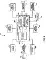
- FIG. 8shows is a block diagram illustrating functional components of exemplary system 300 .
- Diagnostic system 300may include controller function 400 , media interface 410 , power source 420 , user control function 430 , input/output function 440 , indicator function 450 , media dispensing mechanism 460 , voice message function 470 , environmental sensors 480 , and a data connector 490 .
- many of the functional components of the system 300 , or portions thereof,are distributed off of the meter 130 , and are performed by a partner device, such as a computer.
- partner devicessuch as MP3 players, digital cameras, PDA devices, and cell phones, can also be used without departing from the scope of the present invention.
- the meter portion of the systemwhich houses the media interface 410 , can communicate with the partner device by physical connection, or wirelessly, as exemplified in FIG. 6 and discussed above.
- Controller 400controls the operation of the functional components of the meter in accordance with its instructions 402 , which may be provided as software or firmware.
- Controller 400may include microprocessor 404 , onboard memory 406 , and clock functions 408 .
- the processor 404 , memory 406 , and/or clock functions 408may be implemented using an Application Specific Integrated Circuit (ASIC), which allows controller 400 to be reduced in size in comparison to standard integrated circuit technology.
- ASICApplication Specific Integrated Circuit
- the controllermay be implemented using standard integrated circuit technology, or other technology, without departing from the scope of the present invention.
- Processor function 404executes instructions 402 used to control the functional components 410 - 490 of system 300 .
- processor 404executes instructions 402 necessary to perform the diagnostic test (e.g., as set forth in U.S. Pat. Nos. 6,743,635 and 6,946,299, incorporated by reference above).
- the instructions 402 for the processor 404may be stored in memory 406 or elsewhere in the system.
- Memory function 406may also store data, such as calibration data and other data, used in the performance of the diagnostic test as described, for example, in co-pending commonly-assigned U.S. patent application Ser. No. 11/144,715, filed Jun. 6, 2005, and incorporated herein by reference in its entirety.
- memory 406is used to store results of the diagnostic test, which can include additional information such as time/date data and/or associated voice messages, for later processing.
- Clock function 408regulates the processor's execution of the instructions 402 in time.
- clock function 408is used to regulate the timing of steps in the diagnostic test.
- processor 404may use clock 408 to regulate an incubation time period, or other time periods, necessary for the correct performance of the diagnostic test (e.g., as set forth in U.S. Pat. Nos. 6,743,635 and 6,946,299, incorporated by reference above).
- Clock function 408may be implemented by a single system clock or by multiple clocks for different purposes.
- Clock function 408can be the same as, or in addition to, the clock function of crystal oscillator 138 of the data connector 602 , as described above.
- Media interface 410accepts test media, such as test strips 120 , for testing and can include a channel 411 , or keyway, to ensure that the test media is correctly positioned when inserted by a user, or in an alternative embodiment, by the media dispensing mechanism 460 .
- Interface 410includes one or more media sensors for determining, e.g., whether a test strip 120 has been correctly inserted in the test port 410 (i.e., whether interface side 122 of test strip 120 is properly positioned with respect to the media sensors), whether an adequately-sized sample has been applied to the sample chamber on the sample side 121 of the test strip, and the presence or concentration of analyte in the sample.
- the interfacecan also detect strip coding information, as described in commonly-assigned co-pending U.S. patent application Ser. No. 11/181,778, filed Jul. 15, 2005, which is incorporated by reference herein in its entirety.
- Power source 420provides power to the electronic components of meter 130 .
- the power sourceis a lithium coin cell battery.
- other power sourcessuch as other types of batteries, solar cells, or AC/DC converters may be used without departing from the scope of the present invention.
- Powercan be obtained through data connector 490 , e.g., from a USB port of a computer to operate the meter when it is connected, or to recharge a battery.
- the output of the power sourcemay be regulated, e.g., by a voltage regulator circuit.
- User control function 430may include, for example, one or more buttons, switches, keys or other controls for controlling the functions of meter 130 .
- user control function 430is implemented using a single control, e.g., a single button (not shown), that is used to control a plurality of meter functions.
- user control 430may be used to control the input/output function 440 , indicator function 450 , media dispensing mechanism 460 , and/or voice message function 470 , by providing commands to these functions directly or through controller 400 .
- User control 430may also be used to control the diagnostic test function of controller 400 . For example, when a test is performed using a control solution (e.g., as set forth in U.S. Pat.
- the button(not shown) may be held down to indicate to controller 400 that the current sample is a control solution and, consequently, that controller 400 should perform a control test on the current strip.
- a plurality of user controlse.g., a plurality of buttons (not shown), may be provided, with each button having different functions.
- buttonsmay be provided to allow a user to scroll through diagnostic test results stored in the memory 406 , in either forward or reverse directions.
- the function of the button or buttons at the particular timemay be dynamically indicated by indicator function 450 .
- indicator function 450e.g., a display 133 (as shown in FIG. 1 )
- user controlsmay have different functions at different times.
- holding a button (not shown) down upon the insertion of a test strip 120 into media interface 410may command the controller 400 to perform a control test on that strip, whereas, holding the button down without inserting a test strip 120 may command the controller 400 to display the result of the previous diagnostic test.
- the user control functioncan also be implemented by a partner device, such as a PC, MP3 player, cell phone, PDA, etc.
- Input/output function 440provides for the downloading of data or instructions 402 to meter 130 , and/or the uploading of data from meter 130 .
- Input/output function 440may be used, for example, to upload the results of a diagnostic test or tests so that they may be transferred to a storage device, a flash memory 148 , or a third party, via a network connection or wireless link, e.g., a healthcare professional.
- input/output function 440may be used to download data (e.g., calibration data) or instructions 402 (e.g., updated software) to the meter 130 , when appropriate.
- Input/output function 440may be implemented using any conventional digital or analog information interface, e.g., a serial port, a parallel port, an optical port, an infrared interface, etc.
- the input/output functioncan also be implemented by a partner device, such as a PC, MP3 player, cell phone, PDA, etc. Networked partner devices could download and store updates for the meter 130 , and install the updates the next time a connection with the meter 130 is achieved.
- Indicator function 450indicates the result of the diagnostic test to the user, e.g., as a numerical value together with the units of measurement.
- the indicatormay present other information to the user.
- the indicator 450may indicate the average result of a plurality of tests, the time and/or date, remaining battery life, etc. (e.g., as set forth in U.S. Pat. Nos. 6,743,635 and 6,946,299, incorporated by reference above).
- Indicator 450may also be used to prompt the user to perform certain steps of the diagnostic test, e.g., to apply the sample to the test strip 120 .
- indicator 450indicates the number of test strips 120 remaining in container 110 , the number of tests, or the time remaining before meter 130 becomes inoperative.
- Indicator function 450may present information in visible, audible or tactile form.
- indicator 450may include a display 133 for displaying information, e.g., using numerical values, words and/or icons.
- the displaymay be a liquid crystal display (LCD), a vacuum fluorescent display, an electroluminescent display, a LED display, a plasma display, etc.
- display 133is a LCD.
- indicator 450may include an audible indicator configured to indicate information by sound.
- indicator 450may include a speaker connected to a voice and/or sound circuit that is configured to, e.g., speak the result of the diagnostic test or to beep to indicate that an error has occurred.
- indicator 450may be implemented as a dynamic Braille indicator for use by the blind.
- the indicator functioncan also be implemented by a partner device, such as a PC, MP3 player, cell phone, PDA, etc.
- FIG. 9illustrates a cross-section of an exemplary diagnostic system having a media dispensing mechanism 460 .
- the container 110is configured as a spring-loaded magazine 510 .
- a plurality of test strips 120are stacked on top of one another in magazine 510 .
- Magazine 510may have an interior shape similar to that of the test media in order to maintain the alignment of the stack. For example, for the test strip 120 depicted in FIG. 1 , the interior of magazine 510 may be generally rectangular in cross-section.
- Dispensing mechanism 460dispenses the top test strip 125 in the stack using a linear and/or rotational mechanical action.
- the mechanical actionmay be executed manually (e.g., by the user pulling a slide or rotating a wheel) or by a motor 412 (e.g., a stepper motor) actuated by user control function 430 .
- the top test strip 125is slid from the stack and through slot 520 .
- the test media used with this embodimentmay be modified by application of a non-friction coating or film, such as TEFLON, to one or both sides of slot 520 in order to ensure smooth ejection.
- media dispensing mechanism 460may position the interface side 122 of the ejected test strip 125 within media interface 410 , e.g., with the interface side 122 of the test strip engaging the media sensors and the sample chamber 121 of the test strip.
- media dispensing mechanism 460may simply present either end of the top test strip 125 to the user, who may then manually insert the test strip 125 into media interface 410 (either before or after the sample is applied, depending on the requirements of the particular diagnostic test).
- Controller 400may be instructed to count the number of test strips 120 dispensed by media dispensing mechanism 460 and cause indicator function 450 to indicate, e.g., the number of test strips 120 remaining in magazine 510 .
- FIG. 9depicts the meter 130 configured to form an integrated system with magazine 510
- the media dispensing functioncan also be implemented by a partner device, such as a PC, MP3 player, cell phone, PDA, etc, or a separate device altogether.
- Voice message function 470may be used to record a voice message associated with a given diagnostic test result.
- a usermay use voice message function 470 to record information related to their diet around the time of the diagnostic test.
- the voice messagemay be recorded in memory 406 , along with a pointer associating it with a particular test result.
- the use of the voice message function 470is more fully explained in prior application Ser. No. 10/764,974, entitled “MEDICAL DIAGNOSTIC TESTING DEVICE WITH VOICE MESSAGE CAPABILITY,” filed Jan. 26, 2004, commonly assignee with the present application, and incorporated by reference herein in its entirety.
- the metermay be given or sent to the user's medical care provider.
- the healthcare professionalmay then review the results of the diagnostic tests and/or associated voice messages for use in treating the user.
- the voice messagescan also be downloaded with other data to a partner device.
- the voice message function 470can also be implemented by a partner device, such as a PC, MP3 player, cell phone, PDA, etc.
- Environmental sensing function 480may include one or more environmental sensors used to gather data used in the performance of the diagnostic test.
- Such environmental sensorsmay include, e.g., a temperature sensor and/or a humidity sensor.
- meter 130may use a temperature reading to correct the diagnostic test result for temperature dependence (e.g., as set forth in U.S. Pat. Nos. 6,743,635 and 6,946,299, incorporated by reference above).
- meter 130may use a humidity reading to determine if the humidity level is too high to proceed with the diagnostic test.
- the environmental sensing function 480can also be implemented by a partner device, such as a PC, MP3 player, cell phone, PDA, wireless weather station, internet weather service, etc.
- FIG. 10illustrates, in simplified form, a block diagram illustrating functional components of the computer 112 .
- Computer 112can include a power source 246 , an input device 248 , a microcontroller 200 , an output device 250 , a monitor 114 , a data coupling 192 , and a port 116 .
- Possible input devices 248include network interfaces, keyboards, mice, speech recognition devices, or document, video, or image input devices. Additionally, possible output devices 250 include network interfaces, printers, or sound or speech output devices. In an illustrative embodiment, the functional components of the computer 112 are contained within computer housing 240 .
- the computer system 112can also include at least one microcontroller or central processing unit (“CPU”) 200 .
- CPU 200can execute software programs for implementing some of the processes described below with respect to FIG. 11 .
- Software programs for the computer systemcan reside in the memory 206 of the CPU 200 .
- Memory 206can include graphs, charts, etc., and software for manipulating the data.
- Microcontroller 200controls the operation of the functional components of the computer in accordance with its instructions, which can be provided as software or firmware.
- Microcontroller 200can include a processor 198 , memory 206 , input/output ports 242 , and clock functions 244 . These functional components operate similarly to the functional components of controller 400 of meter 130 , as described above.
- a userfirst inserts a test strip 120 into the diagnostic meter 130 in step 264 .
- the meter 130then performs an analytic test in step 266 , and may display the results on a built-in display 133 of the meter 130 .
- the datacan be uploaded to a personal computer 112 for analysis, or transmitted to another party, such as a healthcare professional.
- a data connectionis established between the meter 130 and a partner device, such as a PC, PDA, MP3 player, cell phone, etc. This connection can be achieved via a USB connector, IEEE-1394 plug, wireless link, or other known connection methods, as described above.
- this data connectioncan be established before the diagnostic test is actually performed, which may be desirable, for instance, where the meter body is powered by the data connection, e.g. a USB connection.
- the partner devicerecognizes the interface, for example through Plug and Play protocols, and may optionally execute interface software contained resident in the memory of the meter 130 , as illustrated in step 272 .
- the desired test datais then transmitted from the meter 130 to the partner device as shown in step 274 .
- the test datacan optionally be encrypted with device identification information, including the date and time the test result was obtained, a serial number of the meter, a user name, or other identifying data.
- the device and patient identification datacan be transmitted from the meter together or sequentially, along with diagnostic test data, such that the computer software recognizes which data belongs with which user.
- the incoming data from the meter 130can then be displayed on a partner device display and/or stored in a partner device memory to be accessed at a later time, as indicated by steps 276 and 278 , respectively.
- the partner device that displays the test results in step 276and the partner device that stores the test results, need not ultimately be the same device.
- the results from the diagnostic testmay be displayed on a cell phone and subsequently stored on a hard drive of a PC.
- the partner devicecan interface directly with the flash memory 148 of the meter's interface to transfer test data from the diagnostic meter 130 to the partner device.
- diagnostic meter 130may be calibrated for use with a particular lot of test media by coding with appropriate calibration parameters.
- the meteris configured to read a calibration code on the strip.
- the coding schemecan be similar to that described for on-strip coding in co-pending U.S. patent application Ser. No. 11/181,778, filed on Jul. 15, 2005, and commonly assigned with the present application, the contents of which are incorporated herein by reference.
- Another approachis to provide only strips corresponding to a preprogrammed set of calibration data for use with the meter. This approach is sometimes called “universal” coding.
- the diagnostic test systemcan further employ additional safeguards to minimize user error.
- the integrated diagnostic system 100can include one or more preventive measures that may disable one or more functions of the meter 130 upon the occurrence of certain triggering events.
- the triggering eventcan be a certain period of time elapsing, the performance of a predetermined quantity of tests, or with a certain quantity of test media.
- the meter 130may then be simply disposed of or returned to the manufacturer for remanufacturing.
- the preventive measuremay render only the diagnostic testing function of controller 400 inoperative, or simply prevent the meter 130 from displaying the result of a diagnostic test. The user may then retain meter 130 in order to use its remaining functions.
- One having ordinary skill in the artwill understand that many other safeguards may be employed to minimize and prevent meter calibration errors. After the meter is disabled, for example, the memory might still be accessed to download results. A disabled meter, in addition, might facilitate the automatic reordering of supplies through the partner device, e.g. an internet-enabled computer, or a cell phone.
- Systems and methods consistent with the present inventionalso include computer readable media that include program instruction or code for performing various computer-implemented operations based on the methods and processes of the invention.
- the media and program instructionscan be those specially designed and constructed for the purposes of the invention, or they can be of the kind well-known and available to those having skill in the computer software arts.
Landscapes
- Health & Medical Sciences (AREA)
- Life Sciences & Earth Sciences (AREA)
- Engineering & Computer Science (AREA)
- Physics & Mathematics (AREA)
- Biomedical Technology (AREA)
- Biophysics (AREA)
- General Health & Medical Sciences (AREA)
- Molecular Biology (AREA)
- Chemical & Material Sciences (AREA)
- Medical Informatics (AREA)
- Pathology (AREA)
- Optics & Photonics (AREA)
- Public Health (AREA)
- Urology & Nephrology (AREA)
- Veterinary Medicine (AREA)
- Analytical Chemistry (AREA)
- General Physics & Mathematics (AREA)
- Immunology (AREA)
- Medicinal Chemistry (AREA)
- Biochemistry (AREA)
- Heart & Thoracic Surgery (AREA)
- Food Science & Technology (AREA)
- Surgery (AREA)
- Animal Behavior & Ethology (AREA)
- Hematology (AREA)
- Emergency Medicine (AREA)
- Databases & Information Systems (AREA)
- Human Computer Interaction (AREA)
- Epidemiology (AREA)
- Primary Health Care (AREA)
- Computer Networks & Wireless Communication (AREA)
- Automatic Analysis And Handling Materials Therefor (AREA)
- Arrangements For Transmission Of Measured Signals (AREA)
- Measuring Leads Or Probes (AREA)
- Investigating Or Analysing Materials By The Use Of Chemical Reactions (AREA)
- Mobile Radio Communication Systems (AREA)
- Measurement Of The Respiration, Hearing Ability, Form, And Blood Characteristics Of Living Organisms (AREA)
Abstract
Description
Claims (21)
Priority Applications (13)
| Application Number | Priority Date | Filing Date | Title |
|---|---|---|---|
| US11/395,266US8696597B2 (en) | 2006-04-03 | 2006-04-03 | Diagnostic meter |
| TW102139090ATWI532467B (en) | 2006-04-03 | 2007-03-29 | Diagnostic meter |
| TW096111047ATWI422357B (en) | 2006-04-03 | 2007-03-29 | Diagnostic meter |
| PCT/US2007/065763WO2007118046A2 (en) | 2006-04-03 | 2007-04-02 | Diagnostic meter |
| JP2009504403AJP2009532706A (en) | 2006-04-03 | 2007-04-02 | Diagnostic measuring instrument |
| EP07759939AEP2010046A2 (en) | 2006-04-03 | 2007-04-02 | Diagnostic meter |
| MX2008012709AMX2008012709A (en) | 2006-04-03 | 2007-04-02 | Diagnostic meter. |
| BRPI0709105ABRPI0709105A8 (en) | 2006-04-03 | 2007-04-02 | DIAGNOSTIC TEST SYSTEMS AND METHOD OF SUPPLYING DIAGNOSTIC DATA TO A COMPUTER |
| EP11180582.6AEP2394577A3 (en) | 2006-04-03 | 2007-04-02 | Diagnostic meter |
| AU2007234940AAU2007234940B2 (en) | 2006-04-03 | 2007-04-02 | Diagnostic meter |
| NO20084604ANO20084604L (en) | 2006-04-03 | 2008-10-30 | diagnosis Templates |
| JP2014010215AJP5793581B2 (en) | 2006-04-03 | 2014-01-23 | Measuring device apparatus and method for supplying diagnostic test data to a computer |
| JP2015158225AJP2016020913A (en) | 2006-04-03 | 2015-08-10 | Diagnostic measuring instrument |
Applications Claiming Priority (1)
| Application Number | Priority Date | Filing Date | Title |
|---|---|---|---|
| US11/395,266US8696597B2 (en) | 2006-04-03 | 2006-04-03 | Diagnostic meter |
Publications (2)
| Publication Number | Publication Date |
|---|---|
| US20070233395A1 US20070233395A1 (en) | 2007-10-04 |
| US8696597B2true US8696597B2 (en) | 2014-04-15 |
Family
ID=38353873
Family Applications (1)
| Application Number | Title | Priority Date | Filing Date |
|---|---|---|---|
| US11/395,266Active2030-06-17US8696597B2 (en) | 2006-04-03 | 2006-04-03 | Diagnostic meter |
Country Status (9)
| Country | Link |
|---|---|
| US (1) | US8696597B2 (en) |
| EP (2) | EP2010046A2 (en) |
| JP (3) | JP2009532706A (en) |
| AU (1) | AU2007234940B2 (en) |
| BR (1) | BRPI0709105A8 (en) |
| MX (1) | MX2008012709A (en) |
| NO (1) | NO20084604L (en) |
| TW (2) | TWI532467B (en) |
| WO (1) | WO2007118046A2 (en) |
Cited By (5)
| Publication number | Priority date | Publication date | Assignee | Title |
|---|---|---|---|---|
| US9588101B2 (en) | 2014-09-12 | 2017-03-07 | Trividia Health, Inc. | Apparatus for diagnostic meter strip control and identification |
| US9587989B2 (en) | 2011-03-01 | 2017-03-07 | Panasonic Healthcare Holdings Co., Ltd. | Biological sample measurement device |
| US9689831B2 (en) | 2012-01-13 | 2017-06-27 | Panasonic Healthcare Holdings Co., Ltd. | Sensor discharge mechanism for a biological information measurement device |
| US9807543B2 (en) | 2014-04-17 | 2017-10-31 | Z-Integrated Digital Technologies, Inc. | Electronic test device data communication |
| US9928573B2 (en) | 2011-12-27 | 2018-03-27 | Panasonic Healthcare Holdings Co., Ltd. | Biological sample measuring device |
Families Citing this family (117)
| Publication number | Priority date | Publication date | Assignee | Title |
|---|---|---|---|---|
| US6391005B1 (en) | 1998-03-30 | 2002-05-21 | Agilent Technologies, Inc. | Apparatus and method for penetration with shaft having a sensor for sensing penetration depth |
| US8641644B2 (en) | 2000-11-21 | 2014-02-04 | Sanofi-Aventis Deutschland Gmbh | Blood testing apparatus having a rotatable cartridge with multiple lancing elements and testing means |
| US9226699B2 (en) | 2002-04-19 | 2016-01-05 | Sanofi-Aventis Deutschland Gmbh | Body fluid sampling module with a continuous compression tissue interface surface |
| US7041068B2 (en) | 2001-06-12 | 2006-05-09 | Pelikan Technologies, Inc. | Sampling module device and method |
| US9795747B2 (en) | 2010-06-02 | 2017-10-24 | Sanofi-Aventis Deutschland Gmbh | Methods and apparatus for lancet actuation |
| EP1395185B1 (en) | 2001-06-12 | 2010-10-27 | Pelikan Technologies Inc. | Electric lancet actuator |
| JP4209767B2 (en) | 2001-06-12 | 2009-01-14 | ペリカン テクノロジーズ インコーポレイテッド | Self-optimized cutting instrument with adaptive means for temporary changes in skin properties |
| US7749174B2 (en) | 2001-06-12 | 2010-07-06 | Pelikan Technologies, Inc. | Method and apparatus for lancet launching device intergrated onto a blood-sampling cartridge |
| US9427532B2 (en) | 2001-06-12 | 2016-08-30 | Sanofi-Aventis Deutschland Gmbh | Tissue penetration device |
| US8337419B2 (en) | 2002-04-19 | 2012-12-25 | Sanofi-Aventis Deutschland Gmbh | Tissue penetration device |
| US7981056B2 (en) | 2002-04-19 | 2011-07-19 | Pelikan Technologies, Inc. | Methods and apparatus for lancet actuation |
| US7344507B2 (en) | 2002-04-19 | 2008-03-18 | Pelikan Technologies, Inc. | Method and apparatus for lancet actuation |
| US7976476B2 (en) | 2002-04-19 | 2011-07-12 | Pelikan Technologies, Inc. | Device and method for variable speed lancet |
| US7297122B2 (en) | 2002-04-19 | 2007-11-20 | Pelikan Technologies, Inc. | Method and apparatus for penetrating tissue |
| US7674232B2 (en) | 2002-04-19 | 2010-03-09 | Pelikan Technologies, Inc. | Method and apparatus for penetrating tissue |
| US9314194B2 (en) | 2002-04-19 | 2016-04-19 | Sanofi-Aventis Deutschland Gmbh | Tissue penetration device |
| US8702624B2 (en) | 2006-09-29 | 2014-04-22 | Sanofi-Aventis Deutschland Gmbh | Analyte measurement device with a single shot actuator |
| US7909778B2 (en) | 2002-04-19 | 2011-03-22 | Pelikan Technologies, Inc. | Method and apparatus for penetrating tissue |
| US7901362B2 (en) | 2002-04-19 | 2011-03-08 | Pelikan Technologies, Inc. | Method and apparatus for penetrating tissue |
| US7708701B2 (en) | 2002-04-19 | 2010-05-04 | Pelikan Technologies, Inc. | Method and apparatus for a multi-use body fluid sampling device |
| US8360992B2 (en) | 2002-04-19 | 2013-01-29 | Sanofi-Aventis Deutschland Gmbh | Method and apparatus for penetrating tissue |
| US8221334B2 (en) | 2002-04-19 | 2012-07-17 | Sanofi-Aventis Deutschland Gmbh | Method and apparatus for penetrating tissue |
| US7547287B2 (en) | 2002-04-19 | 2009-06-16 | Pelikan Technologies, Inc. | Method and apparatus for penetrating tissue |
| US8372016B2 (en) | 2002-04-19 | 2013-02-12 | Sanofi-Aventis Deutschland Gmbh | Method and apparatus for body fluid sampling and analyte sensing |
| US7331931B2 (en) | 2002-04-19 | 2008-02-19 | Pelikan Technologies, Inc. | Method and apparatus for penetrating tissue |
| US7232451B2 (en) | 2002-04-19 | 2007-06-19 | Pelikan Technologies, Inc. | Method and apparatus for penetrating tissue |
| US9248267B2 (en) | 2002-04-19 | 2016-02-02 | Sanofi-Aventis Deustchland Gmbh | Tissue penetration device |
| US7491178B2 (en) | 2002-04-19 | 2009-02-17 | Pelikan Technologies, Inc. | Method and apparatus for penetrating tissue |
| US9795334B2 (en) | 2002-04-19 | 2017-10-24 | Sanofi-Aventis Deutschland Gmbh | Method and apparatus for penetrating tissue |
| US7229458B2 (en) | 2002-04-19 | 2007-06-12 | Pelikan Technologies, Inc. | Method and apparatus for penetrating tissue |
| US8267870B2 (en) | 2002-04-19 | 2012-09-18 | Sanofi-Aventis Deutschland Gmbh | Method and apparatus for body fluid sampling with hybrid actuation |
| US7892183B2 (en) | 2002-04-19 | 2011-02-22 | Pelikan Technologies, Inc. | Method and apparatus for body fluid sampling and analyte sensing |
| US8784335B2 (en) | 2002-04-19 | 2014-07-22 | Sanofi-Aventis Deutschland Gmbh | Body fluid sampling device with a capacitive sensor |
| US8579831B2 (en) | 2002-04-19 | 2013-11-12 | Sanofi-Aventis Deutschland Gmbh | Method and apparatus for penetrating tissue |
| US8574895B2 (en) | 2002-12-30 | 2013-11-05 | Sanofi-Aventis Deutschland Gmbh | Method and apparatus using optical techniques to measure analyte levels |
| DE602004028463D1 (en) | 2003-05-30 | 2010-09-16 | Pelikan Technologies Inc | METHOD AND DEVICE FOR INJECTING LIQUID |
| US7850621B2 (en) | 2003-06-06 | 2010-12-14 | Pelikan Technologies, Inc. | Method and apparatus for body fluid sampling and analyte sensing |
| WO2006001797A1 (en) | 2004-06-14 | 2006-01-05 | Pelikan Technologies, Inc. | Low pain penetrating |
| US8282576B2 (en) | 2003-09-29 | 2012-10-09 | Sanofi-Aventis Deutschland Gmbh | Method and apparatus for an improved sample capture device |
| EP1680014A4 (en) | 2003-10-14 | 2009-01-21 | Pelikan Technologies Inc | METHOD AND DEVICE FOR A VARIABLE USER INTERFACE |
| US7822454B1 (en) | 2005-01-03 | 2010-10-26 | Pelikan Technologies, Inc. | Fluid sampling device with improved analyte detecting member configuration |
| US8668656B2 (en) | 2003-12-31 | 2014-03-11 | Sanofi-Aventis Deutschland Gmbh | Method and apparatus for improving fluidic flow and sample capture |
| WO2006011062A2 (en) | 2004-05-20 | 2006-02-02 | Albatros Technologies Gmbh & Co. Kg | Printable hydrogel for biosensors |
| WO2005120365A1 (en) | 2004-06-03 | 2005-12-22 | Pelikan Technologies, Inc. | Method and apparatus for a fluid sampling device |
| US9775553B2 (en) | 2004-06-03 | 2017-10-03 | Sanofi-Aventis Deutschland Gmbh | Method and apparatus for a fluid sampling device |
| US8652831B2 (en) | 2004-12-30 | 2014-02-18 | Sanofi-Aventis Deutschland Gmbh | Method and apparatus for analyte measurement test time |
| US7467065B2 (en)* | 2005-05-02 | 2008-12-16 | Home Diagnostics, Inc. | Computer interface for diagnostic meter |
| US8016154B2 (en)* | 2005-05-25 | 2011-09-13 | Lifescan, Inc. | Sensor dispenser device and method of use |
| TW200719865A (en)* | 2005-11-30 | 2007-06-01 | Kuo-Yuan Chang | Simple and easy measuring device of physiological signal having Universal Serial Bus |
| US8696597B2 (en) | 2006-04-03 | 2014-04-15 | Nipro Diagnostics, Inc. | Diagnostic meter |
| US7846110B2 (en)* | 2006-08-03 | 2010-12-07 | Advanced Medical Products Gmbh | Self-contained test unit for testing body fluids |
| US9029157B2 (en)* | 2007-04-12 | 2015-05-12 | Nipro Diagnostics, Inc. | Error detection and rejection for a diagnostic testing system |
| ES2693097T3 (en) | 2007-05-30 | 2018-12-07 | Ascensia Diabetes Care Holdings Ag | System and method for managing health data |
| US8001825B2 (en)* | 2007-11-30 | 2011-08-23 | Lifescan, Inc. | Auto-calibrating metering system and method of use |
| MX338871B (en) | 2007-12-10 | 2016-05-04 | Bayer Healthcare Llc | Interface for a health measurement and monitoring system. |
| US9016583B2 (en)* | 2008-02-07 | 2015-04-28 | Arkray, Inc. | Code reading device and data collection system using the same |
| EP2265324B1 (en) | 2008-04-11 | 2015-01-28 | Sanofi-Aventis Deutschland GmbH | Integrated analyte measurement system |
| USD626651S1 (en) | 2008-05-29 | 2010-11-02 | Bayer Healthcare, Llc | Analyte-determining meter |
| GB0812843D0 (en)* | 2008-07-14 | 2008-08-20 | Goosewire Ltd | Data storage devices |
| EP2334249B1 (en) | 2008-09-21 | 2013-03-13 | Syneron Medical Ltd. | A method and apparatus for personal skin treatment |
| EP2187210A1 (en)* | 2008-11-14 | 2010-05-19 | Koninklijke Philips Electronics N.V. | Measurement device for body fluid analysis |
| US8647575B2 (en)* | 2008-11-21 | 2014-02-11 | Terumo Kabushiki Kaisha | Device for measuring blood component |
| JP5320111B2 (en)* | 2009-03-04 | 2013-10-23 | テルモ株式会社 | Blood component measuring device |
| US8323195B2 (en)* | 2008-12-31 | 2012-12-04 | Panasonic Corporation | Blood glucose measurement system |
| US9375169B2 (en) | 2009-01-30 | 2016-06-28 | Sanofi-Aventis Deutschland Gmbh | Cam drive for managing disposable penetrating member actions with a single motor and motor and control system |
| US20100211055A1 (en)* | 2009-02-18 | 2010-08-19 | Shimon Eckhouse | Method for body toning and an integrated data management system for the same |
| EP2434944B1 (en)* | 2009-05-29 | 2014-12-03 | Abbott Diabetes Care, Inc. | Glucose monitoring system with wireless communications |
| US8636661B2 (en)* | 2009-06-04 | 2014-01-28 | Roche Diagnostics Operations, Inc. | Embeddable modules for measuring blood glucose levels |
| US20100331645A1 (en)* | 2009-06-25 | 2010-12-30 | Roche Diagnostics Operations, Inc. | Methods and systems for wireless communication between a blood glucose meter and a portable communication device |
| US9218453B2 (en)* | 2009-06-29 | 2015-12-22 | Roche Diabetes Care, Inc. | Blood glucose management and interface systems and methods |
| US20100331652A1 (en)* | 2009-06-29 | 2010-12-30 | Roche Diagnostics Operations, Inc. | Modular diabetes management systems |
| US9125603B2 (en) | 2009-08-11 | 2015-09-08 | Abbott Diabetes Care Inc. | Analyte sensor ports |
| EP3352108B1 (en)* | 2009-08-11 | 2021-10-06 | Ascensia Diabetes Care Holdings AG | Graphical interface for analyte meter |
| USD627068S1 (en) | 2009-09-22 | 2010-11-09 | Bayer Healthcare, Llc | Analyte-determining meter |
| WO2011039723A1 (en)* | 2009-09-30 | 2011-04-07 | Paul Anthony Yuen | Performance monitoring apparatus and casing therefor |
| PL2322095T3 (en)* | 2009-11-17 | 2018-10-31 | Beurer Gmbh | Measuring device for blood parameters |
| JP5287687B2 (en)* | 2009-12-07 | 2013-09-11 | ニプロ株式会社 | Blood glucose concentration measuring device |
| US20110151571A1 (en)* | 2009-12-23 | 2011-06-23 | Roche Diagnostics Operations, Inc. | Memory apparatus for multiuse analyte test element systems, and kits, systems, combinations and methods relating to same |
| US8965476B2 (en) | 2010-04-16 | 2015-02-24 | Sanofi-Aventis Deutschland Gmbh | Tissue penetration device |
| GB201010737D0 (en)* | 2010-06-25 | 2010-08-11 | Imp Innovations Ltd | Minature HPLC device |
| JP2012032206A (en)* | 2010-07-29 | 2012-02-16 | National Institute Of Advanced Industrial & Technology | Electrochemical analysis device |
| US20120095315A1 (en)* | 2010-10-15 | 2012-04-19 | Roche Diagnostics Operations, Inc. | Configuration of blood glucose meter interfaces |
| WO2012058237A1 (en)* | 2010-10-26 | 2012-05-03 | Abbott Diabetes Care Inc. | Analyte measurement devices and systems, and components and methods related thereto |
| US9713440B2 (en) | 2010-12-08 | 2017-07-25 | Abbott Diabetes Care Inc. | Modular analyte measurement systems, modular components thereof and related methods |
| KR101191255B1 (en)* | 2010-12-31 | 2012-10-16 | 주식회사 필로시스 | Module for Measuring Blood Glucose, Smart phone Combinable with the Module, and Method of Measuring Blood Glucose by Using the Same |
| US8549600B2 (en) | 2011-03-11 | 2013-10-01 | Abbott Point Of Care Inc. | Systems, methods and analyzers for establishing a secure wireless network in point of care testing |
| US8776246B2 (en) | 2011-03-11 | 2014-07-08 | Abbott Point Of Care, Inc. | Systems, methods and analyzers for establishing a secure wireless network in point of care testing |
| WO2012138451A2 (en)* | 2011-04-08 | 2012-10-11 | Csp Technologies, Inc. | Strip dispenser and strips for use with the same |
| KR101234835B1 (en)* | 2011-04-26 | 2013-02-22 | (의료)길의료재단 | A hypertension monitoring and notification device based on context information |
| US20120306628A1 (en)* | 2011-05-31 | 2012-12-06 | Tara Chand Singhal | Integrated blood glucose measurement device with a test strip count system |
| US20120330119A1 (en)* | 2011-06-21 | 2012-12-27 | Gadlight, Inc. | Analyte Testing Device with Lancet Cartridge and Test Strip Cartridge |
| US8475733B2 (en)* | 2011-08-04 | 2013-07-02 | Cilag Gmbh International | Hand-held test meter and analytical test strip cartridge assembly with desiccant vial |
| USD680454S1 (en) | 2011-10-25 | 2013-04-23 | Abbott Diabetes Care Inc. | Analyte meter and strip port |
| EP2866658A2 (en)* | 2012-07-02 | 2015-05-06 | 3Pdx, Llc | Devices, systems, and methods for diagnostic testing |
| JP6165860B2 (en)* | 2012-07-26 | 2017-07-19 | アセンシア・ディアベティス・ケア・ホールディングス・アーゲー | Apparatus and method for reducing risk of electric shock of biosensor measuring device |
| USD706935S1 (en)* | 2013-01-24 | 2014-06-10 | Labstyle Innovation Ltd. | Glucose meter |
| CN103974178A (en)* | 2013-02-06 | 2014-08-06 | 北京怡成生物电子技术有限公司 | Mobile-terminal-based portable detection system |
| WO2014165172A1 (en)* | 2013-03-12 | 2014-10-09 | Nipro Diagnostics, Inc. | Wireless pairing of personal health device with a computing device |
| AU2014244537B2 (en)* | 2013-03-14 | 2018-05-31 | Trividia Health, Inc. | Meters with changeable modules |
| US20150050678A1 (en)* | 2013-08-13 | 2015-02-19 | Lifescan Scotland Limited | Modular analytical test meter |
| KR20160057481A (en)* | 2013-09-24 | 2016-05-23 | 아폴로디엑스, 엘엘씨 | Systems and methods for diagnostic testing |
| US20150160186A1 (en)* | 2013-12-09 | 2015-06-11 | Steven Garner-Richards | Diabetic Testing Supply Dispenser |
| WO2016038505A2 (en)* | 2014-09-08 | 2016-03-17 | Indian Institute Of Science | Electrochemical biosensor and a method of sensing albumin and its complexes |
| USD742524S1 (en)* | 2014-11-17 | 2015-11-03 | Bayer Healthcare Llc | Analyte meter |
| GB2535471A (en)* | 2015-02-16 | 2016-08-24 | Camlab Ltd | A computer device for acting as a meter |
| US11867654B2 (en)* | 2015-05-12 | 2024-01-09 | Indian Institute Of Science | Device and method for detecting creatinine and albumin to creatinine ratio |
| AU2017324053B2 (en)* | 2016-09-08 | 2020-08-06 | Hemex Health, Inc. | Diagnostics systems and methods |
| US11164680B2 (en) | 2016-12-14 | 2021-11-02 | Reliant Immune Diagnostics, Inc. | System and method for initiating telemedicine conference using self-diagnostic test |
| US11915810B2 (en)* | 2016-12-14 | 2024-02-27 | Reliant Immune Diagnostics, Inc. | System and method for transmitting prescription to pharmacy using self-diagnostic test and telemedicine |
| US11295859B2 (en) | 2016-12-14 | 2022-04-05 | Reliant Immune Diagnostics, Inc. | System and method for handing diagnostic test results to telemedicine provider |
| CN110520730A (en)* | 2017-02-21 | 2019-11-29 | 埃吕梅有限公司 | Diagnostic system |
| JP6818002B2 (en)* | 2018-12-12 | 2021-01-20 | 株式会社東芝 | Read support systems, mobiles, read support methods, programs, and storage media |
| CN109856201A (en)* | 2019-01-18 | 2019-06-07 | 深圳和而泰数据资源与云技术有限公司 | Saliva detection device |
| TWI746182B (en)* | 2020-09-24 | 2021-11-11 | 禪譜科技股份有限公司 | Multi channel potentiostat device |
| EP4244862A2 (en) | 2020-11-12 | 2023-09-20 | Redcoat Solutions, Inc. | Apparatus and methods for assaying a liquid sample |
| WO2024086700A1 (en)* | 2022-10-20 | 2024-04-25 | In Vitro Diagnostic Solutions | Capture and use of results for diagnostic assays via point-of-collection devices using mobile devices |
| EP4410198A1 (en) | 2023-01-31 | 2024-08-07 | Nutrix Poland Sp. z o.o. | Read-out device and carrier for analyte detection |
Citations (28)
| Publication number | Priority date | Publication date | Assignee | Title |
|---|---|---|---|---|
| WO1997028736A1 (en) | 1996-02-12 | 1997-08-14 | Nokia Mobile Phones Limited | A method for monitoring the health of a patient |
| US5728074A (en)* | 1994-03-09 | 1998-03-17 | Visionary Medical Products, Inc. | Pen-type injector with a microprocessor and blood characteristic monitor |
| WO2000007013A2 (en) | 1998-07-31 | 2000-02-10 | Abbott Laboratories | Analyte test instrument system including data management system |
| JP2001258867A (en) | 2000-03-17 | 2001-09-25 | Sysmex Corp | Device for on-invasive organism inspection |
| US20020002326A1 (en)* | 1998-08-18 | 2002-01-03 | Causey James D. | Handheld personal data assistant (PDA) with a medical device and method of using the same |
| US20030005336A1 (en)* | 2001-06-28 | 2003-01-02 | Poo Teng Pin | Portable device having biometrics-based authentication capabilities |
| JP2003215122A (en) | 2002-01-24 | 2003-07-30 | Toshiba Corp | Small inspection equipment, precision managing chip and precision managing method of small inspection equipment |
| JP2003288660A (en) | 2001-12-22 | 2003-10-10 | F Hoffmann-La Roche Ag | System having a removable data transfer module for transferring data from an analysis system to a data processing unit |
| WO2003094713A1 (en) | 2002-05-14 | 2003-11-20 | Mediventure Co., Ltd. | Blood sugar tester and data uploading method |
| US20040039255A1 (en)* | 1998-11-30 | 2004-02-26 | Simonsen Jan Henning | Medical system and a method of controlling the system for use by a patient for medical self treatment |
| WO2004090503A2 (en) | 2003-04-04 | 2004-10-21 | Abbott Laboratories | Method and system for transferring analyte test data |
| US20040225832A1 (en)* | 2003-05-07 | 2004-11-11 | Sunplus Technology Co., Ltd. | Portable USB storage device having a storage medium formed of a DRAM |
| US20040260854A1 (en) | 2003-03-28 | 2004-12-23 | Schade Peter Arthur | Dual port USB interface |
| US20040260204A1 (en)* | 2001-10-16 | 2004-12-23 | Agilent Technologies, Inc. | Universal diagnostic platform |
| WO2005011488A2 (en) | 2003-07-25 | 2005-02-10 | Masimo Corporation | Multipurpose sensor port |
| US20050096518A1 (en) | 2003-10-31 | 2005-05-05 | Yu-Hong Chang | Biological test system |
| US20050096565A1 (en)* | 2003-10-31 | 2005-05-05 | Yu-Hong Chang | Compact structure of a new biosensor monitor |
| US20050168747A1 (en) | 2004-01-29 | 2005-08-04 | Fox Shaw G. | Information-encoded tests and method |
| US20050214929A1 (en)* | 2002-05-08 | 2005-09-29 | Jens-Peter Seher | System for point of care diagnosis and/or analysis |
| US20060009684A1 (en) | 2004-07-07 | 2006-01-12 | Steven Kim | System for monitoring compliance to a healthcare regiment of testing |
| WO2006009199A1 (en) | 2004-07-21 | 2006-01-26 | Matsushita Electric Industrial Co., Ltd. | Blood sugar level management system |
| US20060044871A1 (en) | 2004-08-30 | 2006-03-02 | Renesas Technology Corp. | Semiconductor integrated circuit |
| US20070123782A1 (en)* | 2005-11-30 | 2007-05-31 | Jackson Connolly | On-site healthcare diagnostic device |
| US20070208233A1 (en)* | 2006-03-03 | 2007-09-06 | Physiowave Inc. | Integrated physiologic monitoring systems and methods |
| US20070233395A1 (en) | 2006-04-03 | 2007-10-04 | Home Diagnostics, Inc. | Diagnostic meter |
| US20070239990A1 (en)* | 2006-03-29 | 2007-10-11 | Stmicroelectronics, Inc. | Secure mass storage device |
| US7344500B2 (en) | 2004-07-27 | 2008-03-18 | Medtronic Minimed, Inc. | Sensing system with auxiliary display |
| US20100069730A1 (en)* | 2006-03-23 | 2010-03-18 | Chris Bergstrom | System and Methods for Improved Diabetes Data Management and Use Employing Wireless Connectivity Between Patients and Healthcare Providers and Repository of Diabetes Management Information |
Family Cites Families (16)
| Publication number | Priority date | Publication date | Assignee | Title |
|---|---|---|---|---|
| US5321492A (en)* | 1992-08-07 | 1994-06-14 | Miles Inc. | Dual function readhead for a reflectance instrument |
| US5723085A (en) | 1994-10-14 | 1998-03-03 | Capitol Vial, Inc. | Process and apparatus for making a leak proof cap and body assembly |
| US6040195A (en) | 1997-06-10 | 2000-03-21 | Home Diagnostics, Inc. | Diagnostic sanitary test strip |
| US5995236A (en) | 1998-04-13 | 1999-11-30 | Mit Development Corporation | Blood fluid characteristics analysis instrument |
| US20020098122A1 (en)* | 2001-01-22 | 2002-07-25 | Angad Singh | Active disposable microfluidic system with externally actuated micropump |
| US6541266B2 (en) | 2001-02-28 | 2003-04-01 | Home Diagnostics, Inc. | Method for determining concentration of an analyte in a test strip |
| JP2002372994A (en)* | 2001-06-15 | 2002-12-26 | Alpine Electronics Inc | Audio reproducing device and data storage medium |
| FR2831300B1 (en)* | 2001-10-23 | 2004-01-16 | France Telecom | SYSTEM FOR TRANSFERRING GLYCEMIC DATA BETWEEN HEALTHCARE PROFESSIONALS AND DIABETIC PATIENTS, ESPECIALLY IN MOBILITY SITUATIONS |
| JP2003302406A (en)* | 2002-04-05 | 2003-10-24 | Sony Corp | Self blood sugar measurement system and self-blood sugar measurement unit |
| US6743635B2 (en) | 2002-04-25 | 2004-06-01 | Home Diagnostics, Inc. | System and methods for blood glucose sensing |
| US6946299B2 (en) | 2002-04-25 | 2005-09-20 | Home Diagnostics, Inc. | Systems and methods for blood glucose sensing |
| US7069370B2 (en)* | 2003-01-31 | 2006-06-27 | Toshiba Corporation | USB memory storage apparatus with integrated circuit in a connector |
| US8066639B2 (en)* | 2003-06-10 | 2011-11-29 | Abbott Diabetes Care Inc. | Glucose measuring device for use in personal area network |
| US8147426B2 (en)* | 2003-12-31 | 2012-04-03 | Nipro Diagnostics, Inc. | Integrated diagnostic test system |
| US8394337B2 (en)* | 2003-12-31 | 2013-03-12 | Nipro Diagnostics, Inc. | Test strip container with integrated meter |
| US7467065B2 (en)* | 2005-05-02 | 2008-12-16 | Home Diagnostics, Inc. | Computer interface for diagnostic meter |
- 2006
- 2006-04-03USUS11/395,266patent/US8696597B2/enactiveActive
- 2007
- 2007-03-29TWTW102139090Apatent/TWI532467B/enactive
- 2007-03-29TWTW096111047Apatent/TWI422357B/enactive
- 2007-04-02BRBRPI0709105Apatent/BRPI0709105A8/ennot_activeApplication Discontinuation
- 2007-04-02AUAU2007234940Apatent/AU2007234940B2/enactiveActive
- 2007-04-02EPEP07759939Apatent/EP2010046A2/ennot_activeWithdrawn
- 2007-04-02JPJP2009504403Apatent/JP2009532706A/enactivePending
- 2007-04-02MXMX2008012709Apatent/MX2008012709A/enactiveIP Right Grant
- 2007-04-02EPEP11180582.6Apatent/EP2394577A3/ennot_activeWithdrawn
- 2007-04-02WOPCT/US2007/065763patent/WO2007118046A2/enactiveApplication Filing
- 2008
- 2008-10-30NONO20084604Apatent/NO20084604L/enunknown
- 2014
- 2014-01-23JPJP2014010215Apatent/JP5793581B2/enactiveActive
- 2015
- 2015-08-10JPJP2015158225Apatent/JP2016020913A/enactivePending
Patent Citations (34)
| Publication number | Priority date | Publication date | Assignee | Title |
|---|---|---|---|---|
| US5728074A (en)* | 1994-03-09 | 1998-03-17 | Visionary Medical Products, Inc. | Pen-type injector with a microprocessor and blood characteristic monitor |
| JP2000504597A (en) | 1996-02-12 | 2000-04-18 | ノキア モービル フォーンズ リミティド | How to monitor a patient's health |
| WO1997028736A1 (en) | 1996-02-12 | 1997-08-14 | Nokia Mobile Phones Limited | A method for monitoring the health of a patient |
| WO2000007013A2 (en) | 1998-07-31 | 2000-02-10 | Abbott Laboratories | Analyte test instrument system including data management system |
| JP2002521692A (en) | 1998-07-31 | 2002-07-16 | アボット・ラボラトリーズ | Analyte testing instrument system including data management system |
| US20020002326A1 (en)* | 1998-08-18 | 2002-01-03 | Causey James D. | Handheld personal data assistant (PDA) with a medical device and method of using the same |
| US20040039255A1 (en)* | 1998-11-30 | 2004-02-26 | Simonsen Jan Henning | Medical system and a method of controlling the system for use by a patient for medical self treatment |
| JP2001258867A (en) | 2000-03-17 | 2001-09-25 | Sysmex Corp | Device for on-invasive organism inspection |
| US20030005336A1 (en)* | 2001-06-28 | 2003-01-02 | Poo Teng Pin | Portable device having biometrics-based authentication capabilities |
| US20040260204A1 (en)* | 2001-10-16 | 2004-12-23 | Agilent Technologies, Inc. | Universal diagnostic platform |
| JP2003288660A (en) | 2001-12-22 | 2003-10-10 | F Hoffmann-La Roche Ag | System having a removable data transfer module for transferring data from an analysis system to a data processing unit |
| JP2003215122A (en) | 2002-01-24 | 2003-07-30 | Toshiba Corp | Small inspection equipment, precision managing chip and precision managing method of small inspection equipment |
| US20050214929A1 (en)* | 2002-05-08 | 2005-09-29 | Jens-Peter Seher | System for point of care diagnosis and/or analysis |
| JP2005525161A (en) | 2002-05-14 | 2005-08-25 | ヘルスピア カンパニー,リミテッド | Blood glucose measurement device and data upload method |
| WO2003094713A1 (en) | 2002-05-14 | 2003-11-20 | Mediventure Co., Ltd. | Blood sugar tester and data uploading method |
| US20040260854A1 (en) | 2003-03-28 | 2004-12-23 | Schade Peter Arthur | Dual port USB interface |
| US20040249999A1 (en) | 2003-04-04 | 2004-12-09 | Connolly Brian Edmond | Method and system for transferring analyte test data |
| WO2004090503A2 (en) | 2003-04-04 | 2004-10-21 | Abbott Laboratories | Method and system for transferring analyte test data |
| US20040225832A1 (en)* | 2003-05-07 | 2004-11-11 | Sunplus Technology Co., Ltd. | Portable USB storage device having a storage medium formed of a DRAM |
| WO2005011488A2 (en) | 2003-07-25 | 2005-02-10 | Masimo Corporation | Multipurpose sensor port |
| US20050096565A1 (en)* | 2003-10-31 | 2005-05-05 | Yu-Hong Chang | Compact structure of a new biosensor monitor |
| US20050096518A1 (en) | 2003-10-31 | 2005-05-05 | Yu-Hong Chang | Biological test system |
| US20050168747A1 (en) | 2004-01-29 | 2005-08-04 | Fox Shaw G. | Information-encoded tests and method |
| US20060009684A1 (en) | 2004-07-07 | 2006-01-12 | Steven Kim | System for monitoring compliance to a healthcare regiment of testing |
| US20080045819A1 (en) | 2004-07-21 | 2008-02-21 | Matsushita Electric Industrial Co., Ltd. | Blood-Sugar Level Management System |
| WO2006009199A1 (en) | 2004-07-21 | 2006-01-26 | Matsushita Electric Industrial Co., Ltd. | Blood sugar level management system |
| US7344500B2 (en) | 2004-07-27 | 2008-03-18 | Medtronic Minimed, Inc. | Sensing system with auxiliary display |
| JP2006066009A (en) | 2004-08-30 | 2006-03-09 | Renesas Technology Corp | Semiconductor integrated circuit |
| US20060044871A1 (en) | 2004-08-30 | 2006-03-02 | Renesas Technology Corp. | Semiconductor integrated circuit |
| US20070123782A1 (en)* | 2005-11-30 | 2007-05-31 | Jackson Connolly | On-site healthcare diagnostic device |
| US20070208233A1 (en)* | 2006-03-03 | 2007-09-06 | Physiowave Inc. | Integrated physiologic monitoring systems and methods |
| US20100069730A1 (en)* | 2006-03-23 | 2010-03-18 | Chris Bergstrom | System and Methods for Improved Diabetes Data Management and Use Employing Wireless Connectivity Between Patients and Healthcare Providers and Repository of Diabetes Management Information |
| US20070239990A1 (en)* | 2006-03-29 | 2007-10-11 | Stmicroelectronics, Inc. | Secure mass storage device |
| US20070233395A1 (en) | 2006-04-03 | 2007-10-04 | Home Diagnostics, Inc. | Diagnostic meter |
Non-Patent Citations (11)
| Title |
|---|
| AU Examination Report dated Mar. 27, 2012, issued in Australian Patent Application No. 2007234940. |
| EP Examination Reported dated Sep. 8, 2009, issued in European Patent Application No. 07759939.7. |
| International Search Report received from the European Patent Office, dated Oct. 22, 2007. |
| JP Office Action dated Oct. 10, 2012, issued in Japanese Patent Application No. 2009-504403. |
| JP Office Action dated Oct. 14, 2011, issued in Japanese Patent Application No. 2009-504403. |
| MX Office Action dated Jan. 25, 2012, issued in Mexican Patent Application No. MX/a/2008/012709. |
| MX Office Action dated Jun. 22, 2012, issued in Mexican Patent Application No. MX/a/2008/012709. |
| PCT International Preliminary Report on Patentability, issued in International Application No. PCT/US2007/065763 dated Oct. 8, 2008. |
| PCT Notification of Transmittal of the International Search Report and the Written Opinion of the International Searching Authority, issued in International Application No. PCT/US2007/065763 dated Oct. 22, 2007. |
| PCT Written Opinion of the International Searching Authority, issued in International Application No. PCT/US2007/065763 dated Oct. 22, 2007. |
| Taiwanese Search Report issued in Taiwanese Patent Application No. 96111047 dated Nov. 2, 2012. |
Cited By (8)
| Publication number | Priority date | Publication date | Assignee | Title |
|---|---|---|---|---|
| US9587989B2 (en) | 2011-03-01 | 2017-03-07 | Panasonic Healthcare Holdings Co., Ltd. | Biological sample measurement device |
| US9921227B2 (en) | 2011-03-01 | 2018-03-20 | Panasonic Healthcare Holdings Co., Ltd. | Biological information measurement method |
| US9928573B2 (en) | 2011-12-27 | 2018-03-27 | Panasonic Healthcare Holdings Co., Ltd. | Biological sample measuring device |
| US9689831B2 (en) | 2012-01-13 | 2017-06-27 | Panasonic Healthcare Holdings Co., Ltd. | Sensor discharge mechanism for a biological information measurement device |
| US9807543B2 (en) | 2014-04-17 | 2017-10-31 | Z-Integrated Digital Technologies, Inc. | Electronic test device data communication |
| US10681516B2 (en) | 2014-04-17 | 2020-06-09 | Z-Integrated Digital Technologies, Inc. | Electronic test device data communication |
| US9588101B2 (en) | 2014-09-12 | 2017-03-07 | Trividia Health, Inc. | Apparatus for diagnostic meter strip control and identification |
| US10416148B2 (en) | 2014-09-12 | 2019-09-17 | Trividia Health, Inc. | Apparatus for diagnostic meter strip control and identification |
Also Published As
| Publication number | Publication date |
|---|---|
| JP2014122907A (en) | 2014-07-03 |
| BRPI0709105A2 (en) | 2011-06-28 |
| JP2016020913A (en) | 2016-02-04 |
| WO2007118046A3 (en) | 2007-12-13 |
| TWI532467B (en) | 2016-05-11 |
| JP5793581B2 (en) | 2015-10-14 |
| TW201410209A (en) | 2014-03-16 |
| JP2009532706A (en) | 2009-09-10 |
| TWI422357B (en) | 2014-01-11 |
| TW200744536A (en) | 2007-12-16 |
| BRPI0709105A8 (en) | 2017-08-29 |
| EP2394577A2 (en) | 2011-12-14 |
| AU2007234940B2 (en) | 2013-05-09 |
| EP2394577A3 (en) | 2013-10-30 |
| NO20084604L (en) | 2008-12-29 |
| AU2007234940A2 (en) | 2010-04-22 |
| EP2010046A2 (en) | 2009-01-07 |
| WO2007118046A2 (en) | 2007-10-18 |
| AU2007234940A1 (en) | 2007-10-18 |
| MX2008012709A (en) | 2008-10-15 |
| US20070233395A1 (en) | 2007-10-04 |
Similar Documents
| Publication | Publication Date | Title |
|---|---|---|
| US8696597B2 (en) | Diagnostic meter | |
| EP1706024B1 (en) | Integrated diagnostic test system | |
| US7467065B2 (en) | Computer interface for diagnostic meter | |
| US8394337B2 (en) | Test strip container with integrated meter | |
| TWI544443B (en) | System and method for managing health information | |
| AU2013211564B2 (en) | Diagnostic meter |
Legal Events
| Date | Code | Title | Description |
|---|---|---|---|
| AS | Assignment | Owner name:HOME DIAGNOSTICS, INC., FLORIDA Free format text:ASSIGNMENT OF ASSIGNORS INTEREST;ASSIGNORS:NEEL, GARY T.;MODZELEWSKI, BRENT E.;ROUNDS, GEORGE;AND OTHERS;REEL/FRAME:017762/0494 Effective date:20060329 | |
| AS | Assignment | Owner name:NIPRO DIAGNOSTICS, INC., FLORIDA Free format text:CHANGE OF NAME;ASSIGNOR:HOME DIAGNOSTICS, INC.;REEL/FRAME:024678/0455 Effective date:20100607 | |
| FEPP | Fee payment procedure | Free format text:PAYOR NUMBER ASSIGNED (ORIGINAL EVENT CODE: ASPN); ENTITY STATUS OF PATENT OWNER: LARGE ENTITY | |
| STCF | Information on status: patent grant | Free format text:PATENTED CASE | |
| AS | Assignment | Owner name:TRIVIDIA HEALTH, INC., FLORIDA Free format text:CHANGE OF NAME;ASSIGNOR:NIPRO DIAGNOSTICS, INC.;REEL/FRAME:038002/0867 Effective date:20160107 | |
| AS | Assignment | Owner name:WELLS FARGO BANK, NATIONAL ASSOCIATION, AS ADMINISTRATIVE AGENT, CALIFORNIA Free format text:SECURITY INTEREST;ASSIGNOR:TRIVIDIA HEALTH, INC.;REEL/FRAME:041613/0842 Effective date:20170317 Owner name:WELLS FARGO BANK, NATIONAL ASSOCIATION, AS ADMINIS Free format text:SECURITY INTEREST;ASSIGNOR:TRIVIDIA HEALTH, INC.;REEL/FRAME:041613/0842 Effective date:20170317 | |
| MAFP | Maintenance fee payment | Free format text:PAYMENT OF MAINTENANCE FEE, 4TH YEAR, LARGE ENTITY (ORIGINAL EVENT CODE: M1551) Year of fee payment:4 | |
| MAFP | Maintenance fee payment | Free format text:PAYMENT OF MAINTENANCE FEE, 8TH YEAR, LARGE ENTITY (ORIGINAL EVENT CODE: M1552); ENTITY STATUS OF PATENT OWNER: LARGE ENTITY Year of fee payment:8 | |
| AS | Assignment | Owner name:TRIVIDIA HEALTH, INC., FLORIDA Free format text:RELEASE BY SECURED PARTY;ASSIGNOR:WELLS FARGO BANK, NATIONAL ASSOCIATION;REEL/FRAME:072220/0966 Effective date:20250819 Owner name:TRIVIDIA HEALTHCARE SYSTEMS, LLC, FLORIDA Free format text:RELEASE BY SECURED PARTY;ASSIGNOR:WELLS FARGO BANK, NATIONAL ASSOCIATION;REEL/FRAME:072220/0966 Effective date:20250819 |