US8696588B2 - Device and method for determining a respiration rate - Google Patents
Device and method for determining a respiration rateDownload PDFInfo
- Publication number
- US8696588B2 US8696588B2US11/877,910US87791007AUS8696588B2US 8696588 B2US8696588 B2US 8696588B2US 87791007 AUS87791007 AUS 87791007AUS 8696588 B2US8696588 B2US 8696588B2
- Authority
- US
- United States
- Prior art keywords
- sensor
- respiration rate
- quality value
- evaluating
- subject
- Prior art date
- Legal status (The legal status is an assumption and is not a legal conclusion. Google has not performed a legal analysis and makes no representation as to the accuracy of the status listed.)
- Expired - Fee Related, expires
Links
- 230000029058respiratory gaseous exchangeEffects0.000titleclaimsabstractdescription128
- 238000000034methodMethods0.000titleclaimsabstractdescription19
- 238000005259measurementMethods0.000claimsabstractdescription22
- 230000033001locomotionEffects0.000claimsdescription25
- 230000000694effectsEffects0.000claimsdescription6
- 238000012935AveragingMethods0.000claimsdescription5
- 238000001228spectrumMethods0.000claimsdescription3
- 238000012544monitoring processMethods0.000abstractdescription14
- 230000001133accelerationEffects0.000description9
- 230000008901benefitEffects0.000description8
- 210000000038chestAnatomy0.000description8
- 230000008859changeEffects0.000description7
- 230000037081physical activityEffects0.000description5
- 238000004891communicationMethods0.000description4
- 230000001419dependent effectEffects0.000description4
- 238000013461designMethods0.000description4
- 230000000241respiratory effectEffects0.000description4
- 210000000115thoracic cavityAnatomy0.000description4
- 206010011224CoughDiseases0.000description3
- 230000017525heat dissipationEffects0.000description3
- 238000013186photoplethysmographyMethods0.000description3
- 230000003187abdominal effectEffects0.000description2
- 210000000988bone and boneAnatomy0.000description2
- 238000004364calculation methodMethods0.000description2
- 230000008878couplingEffects0.000description2
- 238000010168coupling processMethods0.000description2
- 238000005859coupling reactionMethods0.000description2
- 239000007789gasSubstances0.000description2
- 230000003862health statusEffects0.000description2
- 238000000691measurement methodMethods0.000description2
- 230000000737periodic effectEffects0.000description2
- BASFCYQUMIYNBI-UHFFFAOYSA-NplatinumChemical compound[Pt]BASFCYQUMIYNBI-UHFFFAOYSA-N0.000description2
- 230000005855radiationEffects0.000description2
- 210000003454tympanic membraneAnatomy0.000description2
- 101000614399Homo sapiens Serine/threonine-protein phosphatase 2A regulatory subunit B'' subunit betaProteins0.000description1
- 206010021079HypopnoeaDiseases0.000description1
- 241001465754MetazoaSpecies0.000description1
- 102100040471Serine/threonine-protein phosphatase 2A regulatory subunit B'' subunit betaHuman genes0.000description1
- 210000000683abdominal cavityAnatomy0.000description1
- 230000003044adaptive effectEffects0.000description1
- 230000004075alterationEffects0.000description1
- 230000003321amplificationEffects0.000description1
- 238000004458analytical methodMethods0.000description1
- 238000003491arrayMethods0.000description1
- QVGXLLKOCUKJST-UHFFFAOYSA-Natomic oxygenChemical compound[O]QVGXLLKOCUKJST-UHFFFAOYSA-N0.000description1
- 230000005540biological transmissionEffects0.000description1
- 230000015572biosynthetic processEffects0.000description1
- 230000000747cardiac effectEffects0.000description1
- 230000000295complement effectEffects0.000description1
- 230000001010compromised effectEffects0.000description1
- 238000001816coolingMethods0.000description1
- 238000012937correctionMethods0.000description1
- 238000001514detection methodMethods0.000description1
- 239000003814drugSubstances0.000description1
- 230000007613environmental effectEffects0.000description1
- 238000001914filtrationMethods0.000description1
- 230000006870functionEffects0.000description1
- 230000010354integrationEffects0.000description1
- 230000004060metabolic processEffects0.000description1
- 239000002207metaboliteSubstances0.000description1
- 238000003199nucleic acid amplification methodMethods0.000description1
- 239000001301oxygenSubstances0.000description1
- 229910052760oxygenInorganic materials0.000description1
- 229910052697platinumInorganic materials0.000description1
- 238000012545processingMethods0.000description1
- 238000003908quality control methodMethods0.000description1
- 230000009467reductionEffects0.000description1
- 230000004044responseEffects0.000description1
- 230000035945sensitivityEffects0.000description1
- 238000000926separation methodMethods0.000description1
- 210000001519tissueAnatomy0.000description1
- 238000012549trainingMethods0.000description1
- 238000011426transformation methodMethods0.000description1
- 230000001960triggered effectEffects0.000description1
- 230000002792vascularEffects0.000description1
- 230000036642wellbeingEffects0.000description1
Images

Classifications
- A—HUMAN NECESSITIES
- A61—MEDICAL OR VETERINARY SCIENCE; HYGIENE
- A61B—DIAGNOSIS; SURGERY; IDENTIFICATION
- A61B5/00—Measuring for diagnostic purposes; Identification of persons
- A61B5/08—Measuring devices for evaluating the respiratory organs
- A61B5/0816—Measuring devices for examining respiratory frequency
- A—HUMAN NECESSITIES
- A61—MEDICAL OR VETERINARY SCIENCE; HYGIENE
- A61B—DIAGNOSIS; SURGERY; IDENTIFICATION
- A61B5/00—Measuring for diagnostic purposes; Identification of persons
- A61B5/08—Measuring devices for evaluating the respiratory organs
- A61B5/0823—Detecting or evaluating cough events
- A—HUMAN NECESSITIES
- A61—MEDICAL OR VETERINARY SCIENCE; HYGIENE
- A61B—DIAGNOSIS; SURGERY; IDENTIFICATION
- A61B5/00—Measuring for diagnostic purposes; Identification of persons
- A61B5/68—Arrangements of detecting, measuring or recording means, e.g. sensors, in relation to patient
- A61B5/6801—Arrangements of detecting, measuring or recording means, e.g. sensors, in relation to patient specially adapted to be attached to or worn on the body surface
- A61B5/6813—Specially adapted to be attached to a specific body part
- A61B5/6814—Head
- A61B5/6815—Ear
- A61B5/6817—Ear canal
- A—HUMAN NECESSITIES
- A61—MEDICAL OR VETERINARY SCIENCE; HYGIENE
- A61B—DIAGNOSIS; SURGERY; IDENTIFICATION
- A61B5/00—Measuring for diagnostic purposes; Identification of persons
- A61B5/05—Detecting, measuring or recording for diagnosis by means of electric currents or magnetic fields; Measuring using microwaves or radio waves
- A61B5/053—Measuring electrical impedance or conductance of a portion of the body
- A61B5/0535—Impedance plethysmography
- A—HUMAN NECESSITIES
- A61—MEDICAL OR VETERINARY SCIENCE; HYGIENE
- A61B—DIAGNOSIS; SURGERY; IDENTIFICATION
- A61B5/00—Measuring for diagnostic purposes; Identification of persons
- A61B5/08—Measuring devices for evaluating the respiratory organs
- A61B5/085—Measuring impedance of respiratory organs or lung elasticity
- A61B5/086—Measuring impedance of respiratory organs or lung elasticity by impedance pneumography
- A—HUMAN NECESSITIES
- A61—MEDICAL OR VETERINARY SCIENCE; HYGIENE
- A61B—DIAGNOSIS; SURGERY; IDENTIFICATION
- A61B5/00—Measuring for diagnostic purposes; Identification of persons
- A61B5/72—Signal processing specially adapted for physiological signals or for diagnostic purposes
- A61B5/7203—Signal processing specially adapted for physiological signals or for diagnostic purposes for noise prevention, reduction or removal
- A61B5/7207—Signal processing specially adapted for physiological signals or for diagnostic purposes for noise prevention, reduction or removal of noise induced by motion artifacts
- A61B5/721—Signal processing specially adapted for physiological signals or for diagnostic purposes for noise prevention, reduction or removal of noise induced by motion artifacts using a separate sensor to detect motion or using motion information derived from signals other than the physiological signal to be measured
- A—HUMAN NECESSITIES
- A61—MEDICAL OR VETERINARY SCIENCE; HYGIENE
- A61B—DIAGNOSIS; SURGERY; IDENTIFICATION
- A61B7/00—Instruments for auscultation
- A61B7/003—Detecting lung or respiration noise
Definitions
- the present inventionpertains to a device for determining a respiration rate and pertains to a method for determining a respiration rate as well as to a monitor.
- respiration rateis an important indicator of the well-being and the health status of a human being.
- An illness or state of stressis often reflected by changes in the respiration rate.
- the monitoring of the respiration ratetherefore regularly makes an important contribution to the monitoring of the state of stress and the health status of the person being monitored.
- respiration rate monitorsfor use in hospitals as well as outside hospitals are currently known in medicine for monitoring the respiration rate.
- One example of such a monitor or such a device for monitoring respirationis known from DE 40 11 065 A1.
- the prior-art devicesdo not meet the requirements imposed concerning clinical handling, reliability, accuracy and reproducibility of the measurement results. This is due especially to the fact that the devices currently available for monitoring respiration and for measuring the respiration rate are either complicated technically and in terms of design and are felt to be disturbing by the user or the person being monitored, and this is especially true of devices for use outside hospitals and for use by mobile, i.e., not bedridden patients, or these devices have a high sensitivity to artifacts.
- the object of the present inventionis therefore to make possible the reliable measurement of the respiration rate of a person. Another object of the present invention is to ensure that the person in question is compromised during the measurement of the respiration rate to the lowest extent possible.
- a device for determining the respiration rateis thus provided according to the present invention, wherein at least two different sensors are used for determining the respiration rate, and these sensors determine the respiration rate in at least two different ways.
- monitoring or measurement of the respiration ratecan also be ensured according to the present invention when a sensor or a measurement method cannot provide sufficiently accurate or reliable data on the respiration rate because of artifacts and/or external circumstances.
- a sensor or a measurement methodcannot provide sufficiently accurate or reliable data on the respiration rate because of artifacts and/or external circumstances.
- the datamay also be inaccurate in case of shallow breathing, which is not recognized as breathing by the motion-dependent sensor.
- the respiration ratecan nevertheless be advantageously determined according to the present invention by resorting to at least one other sensor.
- Another advantage of the device according to the present inventionis that by using more than one sensor, the reliability of the measurement as a whole can be checked. Thus, an alarm or even the outputting of no value for a respiration rate whatsoever may be provided when, e.g., a sensor determines an erroneous value, which conflicts with values of one or more other sensors.
- the user of the device according to the present invention(a user can be defined according to the present invention either as the user of the device or the care provider of the user or a physician) therefore knows that he or she must not rely on the measurement of the respiration rate at such a point in time because at least one sensor is producing an erroneous result.
- Provisionsmay also be made according to the present invention for discarding the non-agreeing value and thus for not taking that value into account for the determination of the respiration rate when the values of the respiration rate determined by, e.g., two or more sensors agree or essentially agree and the value from another sensor does not agree.
- the respiration rateis thus stated as a value ascertained on the basis of different observations, which leads to increased reliability in the determination of the respiration rate.
- These sensorsmay be designed according to the present invention as:
- the chest belthas a suitable coil.
- a preamplifieroscillating circuit
- Electrodesthat determine the impedance of the thoracic cavity by a voltage drop of an alternating current sent through the thoracic cavity with the use of electrodes, for which electrocardiogram (ECG) electrodes possibly already present may also be used;
- ECGelectrocardiogram
- a microphone sensorcan pick up the breath sound in the vicinity of the inlets to the airways, as is described in U.S. Pat. No. 5,143,078;
- Sensorsthat measure a humidity parameter (e.g., a change in dew point) in the vicinity of the inlets to the airway).
- a humidity parametere.g., a change in dew point
- the device according to the present inventioncan be used to determine and monitor the respiration rate in patients as well as in healthy subjects, e.g., athletes, or for bio-feedback
- different combinations of sensors and the corresponding combinations of measurement methodsmay be meaningful. They are therefore also covered by the present invention.
- sensorswhose measuring sites make possible, e.g., a common access (e.g., at the ear only or on the upper body only, etc.).
- a common accesse.g., at the ear only or on the upper body only, etc.
- the latterrepresents a facilitation and simplification for the user in putting on, using and removing the device and hence an advantage according to the present invention.
- Two, three or more different methodscan be used according to the present invention to determine and/or measure the respiration rate and a corresponding number of sensors can be used.
- the present inventionis not limited to certain combinations or a certain number of sensors and ways of measurement.
- the present inventionis also not limited to the above-mentioned sensors.
- the respiration rate measurementmay rather also be carried out in any other way of determining the respiration rate known to the person skilled in the art and also with sensors not mentioned here.
- the device according to the present inventionmay also have more than only one sensor of a particular design. This may be advantageous, e.g., when a sensor of this particular design is prone to failure.
- the device according to the present inventionhas increased reliability of operation in this case even in case of failure of one sensor.
- the respiration rate of the user of the deviceis thus determined according to the present invention such that the different respiration rates measured by different sensors are taken into account.
- the taking into account of more than only one respiration ratemakes possible, especially based on the different methods used for the measurement, the more accurate determination of the actual respiration rate, because the effect of erroneously measured respiration rates by means of individual sensors is effectively mitigated.
- Sliding or dynamic averages of all measured or determined respiration rates, but also other statistical averaging methods, such as the gaussian distribution, the minimization of the sum of the mean squared errors, discarding of the aberrations, and the sliding averaging for past quality valuesare covered by the present invention.
- This statistical correction or averagingmay take place via the sensors at one point in time. However, it may also take place over the time curve of individual signals and/or all measured signals.
- Determination of the respiration ratecovers according to the present invention not only a measuring operation. Measurement along with further processing, filtering, comparison, etc., of signals, which will lead to a usable respiration rate value only thereafter, are also covered by the present invention.
- the present inventionpertains both to the determination and/or monitoring of the respiration rate of a patient in the conventional sense of an ill person and in healthy subjects for monitoring a training schedule during sports activities or the like.
- the present inventionis not, of course, limited to use in humans.
- the respiration rate of animalscan also be monitored by means of the present invention.
- the present inventionmay, furthermore, be associated with the determination or measurement of other parameters.
- an Electrocardiogram (ECG) leadmay be performed, the tidal volume can be determined, the heart rate may be determined, etc., at the same time.
- Sensors that are already provided for the determination of the respiration rateare advantageously used herefor.
- the device according to the present inventionhas at least one means for setting or determining at least one quality value for at least one respiration rate determined by means of one of the sensors. Provisions are therefore made in this embodiment according to the present invention for determining an indicator of the reliability of the signal or respiration rate in question for a respiration rate determined by a sensor. This indicator of the reliability or loadability of the signal or of the respiration rate determined is called the “quality value” according to the present invention.
- This quality valuecan be obtained, e.g., by balancing of the respiration rate determined with quality ranges or stored standard data or the like, which were defined in advance, or by any other plausibility check.
- the quality valuecan also be determined as a function of or in proportion to other, likewise determined signals of the same user.
- the quality value of a signal or of the respiration rate determined herefromthus indicates whether the respiration rate determined by the sensor corresponds to the actual respiration rate with sufficient reliability or whether it comes close to this at least with a manageable uncertainty.
- This quality valueis used for quality control and can be advantageously used in different ways.
- the quality valuemay be determined in another special way that appears suitable to the person skilled in the art.
- a quality value of the respiration rate measured by plethysmographycan be derived, e.g., on the basis of the wave shape, the amplitude and the frequency spectrum and the signal-to-noise ratio.
- the quality valuedoes not have to be determined in the same manner for each respiration rate determined by means of a sensor. Different procedures may be provided here.
- the device according to the present inventionhas a means for determining the respiration rate by taking into account at least two respiration rates determined by means of at least two different sensors. Moreover, the quality values of the respiration rates determined with one or more sensors are taken into account by means of this means in this embodiment.
- a respiration rate of the useris determined in this embodiment such that the different respiration rates measured by different sensors and the quality values thereof (or at least one such quality value) are taken into account.
- the taking into account of the quality values for every “individual” respiration rate of every sensorleads to an advantageous increase in the qualitative information value of the “overall” respiration rate determined over the sensors taken into account.
- the quality valuecan be taken into account according to various mathematical procedures known to the person skilled in the art such that the respiration rate of a sensor, to which a lower or poorer quality value was assigned, has a lower or weaker input to the overall respiration rate than do respiration rates of other sensors with higher or better quality values.
- the quality valuecan be stated as a factor between (including) 0 and (including) 1, and in case of a factor of 0, it causes that the corresponding respiration rate value is not taken into account in the determination of the user's “overall” respiration rate at all.
- the corresponding respiration rateis included in the further determination to the full extent in case of a factor of 1.
- the corresponding respiration ratesare likewise included in the determination proportionally or they are likewise not taken into account in case of factors between 0 and 1. An example will be explained in detail below.
- Quality values from measurements with different sensorscan also be taken into account further with different weights. This makes allowance for the circumstance that a sensor can consistently always yield more reliable results than another sensor and a respiration rate determined with it shall therefore also always be included in the calculation or determination of the respiration rate more strongly.
- the device according to the present inventionhas a means for displaying at least one such quality value.
- the quality or reliability of the respiration rate considered with a certain quality valueis advantageously easy to see in this embodiment, and the user or the attending physician can themselves infer the reliability of the correctness of the value of the measured respiration rate.
- the usercan also check the mode of operation of the sensors and especially the arrangement thereof on or in relation to the body.
- a sound-sensitive sensorcan yield an incorrect count simply because it has slipped such that it chafes, for example, the shirt collar and misinterprets the noises generated hereby.
- the devicealso has at least one evaluating sensor, which shall display mainly information on the quality or reliability of the correctness of the value of the respiration rate measured by means of this sensor.
- a quality value of, e.g., a respiration rate determined by means of an expansion sensor of a chest beltcan be obtained, among other things, by balancing of signals of a motion sensor.
- the signals sent by the motion sensorcan indicate, e.g., that the respiration rate measured by means of the expansion sensor is distorted because of increased physical activity (such as during sports activity).
- An appropriately poorer quality valueis correspondingly assigned to such a sensor.
- a fit of coughing of the user or the user's physical activitymay change the measured respiration rate such that a falsely high respiration rate is displayed in the normal case or an alarm would have to be triggered.
- the simultaneous determination of the physical activity or the detection of a fit of coughing by one or more additional sensors used for this purpose, such as a motion sensorcan be used to determine the quality value and thus used to correctly assess the value and reliability of a respiration rate measured during the fit of coughing.
- Such an evaluating sensorcan measure according to the present invention, e.g., as a motion sensor, the acceleration to recognize and possibly suppress artifacts caused by motion of the user and thus make it possible to infer the user's physical activity.
- the present inventionis accomplished, furthermore, by a method. Since the advantages that can be achieved herewith correspond to those described above in full measure, reference is made here to the advantages discussed above to avoid repetitions.
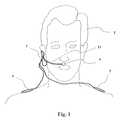
- FIG. 1is a schematic view of a monitor according to the present invention
- FIG. 2is a detail view of the monitor according to FIG. 1 ;
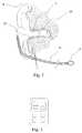
- FIG. 3is a communication unit of the monitor according to FIGS. 1 and 2 .
- FIG. 1shows a monitor 1 , which communicates with the ear and the shoulders as well as an area below the nose of a user T.
- the monitor 1is similar to a mobile radio headset.
- the monitor 1comprises an energy supply of its own (not shown), a control unit, a communication unit, as well as the sensors provided as an example in this embodiment for determining the respiration rate of the user T.
- the monitorhas two cable-bound electrodes 5 , which are arranged at the two shoulders/collarbones of the user T.
- the monitor 1may comprise, furthermore, an ECG amplifier for the electrodes 5 .
- the monitor 1has, furthermore, an acceleration pick-up 7 , which is designed as a three-dimensional motion pick-up in this embodiment.
- a thermal conductivity sensor 9is provided on a strap 11 between the mouth and the nose of the user T.
- An infrared receiver 13is provided in the ear of the user T for measuring the eardrum temperature.
- a sensor 15is provided, which is suitable for use as a transflectory sensor for two-channel (radio (R) and infrared (IR)) photoplethysmography in this embodiment.
- the sensors 5 , 7 and 9detect information on the user T, from which the respiration rate can be determined.
- the sensor 15is also capable of transmitting information on the respiration rate.
- provisionsmay be made for reasons of saving energy for the sensor 15 not being operated continuously but only during an on-time of, e.g., less than 10% of the time. Thus, it preferably supplies only a few pulse cycles over every x minutes.
- Batteries of this typemay be of the zinc-air round cell type (IEC PR48, hearing aid size 13). Comparable batteries may also be used herefor.
- the photoplethysmography sensor 15In case of this isolated, short-term use of the photoplethysmography sensor 15 , this is sufficient for making possible a stable calculation of the oxygen saturation with only a small amount of artifacts. Should the respiration rate measured by means of the sensors 5 , 7 and 9 not be expressive enough, especially in view of the particular quality values of the respiration rate, the sensor 15 may also remain turned on continuously over several minutes (e.g., during an on-time of one msec at 200 Hz) and thus make a contribution to the determination of the respiration rate at the expense of increased power consumption.
- Sensor 5amplifies the electric potentials of the two ECG electrodes, which are preferably positioned at the shoulders or in the collarbone regions.
- the signal obtained from these electrodesis filtered, for which a high-pass filter of 0.05 Hz and a low-pass filter of 10 Hz can be used.
- the signal receivedcontains, on the one hand, the heart rate (pulse) in the range of approximately 1 Hz to 3 Hz (as a cycle frequency, the signal contains far greater frequency components) with an amplitude of approximately 0.2 mVSS (before amplification).
- the signalcontains, in addition, the respiration rates with approximately 0.1 Hz to 0.5 Hz at an amplitude of 0.04 mV.
- Both signal componentscan be recognized by separating the signal contents by means of a fast Fourier transformation method, autocorrelation or an adaptive variable-frequency filter. The assumption that the two frequencies cannot change at any desired rate applies to each possible separation method. If the two frequencies are identified, it is also possible to calculate an amplitude distance from the adjacent or other frequencies being considered.
- Sensor 7is a microstructured acceleration pick-up in this embodiment according to FIG. 1 , whose mass deflection is measured capacitively.
- the sensorcontains three such arrays in order to make possible an independent three-dimensional measurement.
- Sensor 7is positioned directly in the auditory canal and can follow the motion of the bone or the tissue surrounding it.
- the acceleration pick-up 7can be uncoupled from the housing for this.
- the entire monitor 1is designed as a monitor with such a small weight that uncoupling is not necessary to follow the higher frequencies (up to 10 Hz).
- the analysis and the formation of the quality value of the acceleration pick-up 7is performed analogously to the methods described in connection with sensor 5 .
- this sensor or acceleration pick-up 7also provides information from which the activity of the user can be inferred. This is especially advantageous in case of users who are moving about freely, in order to obtain information on the physical exercise of these users in terms of work and motion.
- the extent of the user's physical activitycan also be used to shift the upper limit value for triggering an alarm and represent increased tolerance.
- the thermal conductivity sensor 9is designed in this embodiment according to FIG. 1 as a very small temperature-dependent platinum resistor (PT 100 ).
- This thermal conductivity sensor 9is located at the tip of a strap 11 , which protrudes into the area of the upper edge of the mouth.
- the thermal conductivity sensor 9should be ideally located 3 cm in front of the upper lip.
- the resistorcan be heated with a low measuring current and adjusted to a temperature of approximately 10 K above the ambient temperature. To avoid any risk to the user because of the temperature of the thermal conductivity sensor 9 , this sensor has a very low heat capacity. This is also advantageous for the desired, short response time.
- the heat dissipationis increased during the breath because of the tidal volume flow, which partially also sweeps over the thermal conductivity sensor 9 .
- the temperature and the resistance value thereupondecrease.
- the current that is necessary to maintain the thermal conductivity sensor 9 at the temperature to be stabilizedmeasurably increases, by contrast, corresponding to the increased heat dissipation.
- the heat dissipation of the thermal conductivity sensor 9is approximately 10 mW without an appreciable velocity of flow. If a signal, which contains a sufficient signal distance from noise signals, is generated with this excess temperature, the excess temperature can be reduced, which results in a reduction in power consumption, until the S/N ratio becomes too poor.
- the excess temperaturecan also be increased comparably in case of other signals of a lower quality if no other sensors, which are likewise used, are able to provide a sufficient quality.
- the strap 11may be designed such that it can be folded up in order to prevent the user from being hindered during certain activities or in certain environmental states.
- the thermal conductivity sensor 9 of the strap 11may be designed such that it is turned off automatically when the strap 11 is moved into an “inoperative position” to prevent the user T from being hindered or exposed to risks as well as to prevent erroneous respiration rate measurements.
- the sensor 13is designed as a receiver for infrared radiation in this embodiment. It has a receiver surface and a means for measuring the temperature difference of this surface against the housing by means of thermocouples (chains). An emission factor and the housing temperature are needed for determining the temperature of the radiating surface (the eardrum in this case). The emission factor may be assumed to be constant.
- the housing temperatureis determined by means of conventional temperature sensors. The housing may have a good thermal coupling with the external components of the monitor 1 and a comparatively poor coupling with the auditory meatus. As a result, the greatest possible temperature difference is obtained between the radiating surface and the receiving surface, as a result of which a higher radiation capacity is obtained.
- the frequency to which the highest quality value has been assignedwill be processed further in a special embodiment of the above integration of the individual respiration rates into F respiration .
- FIG. 2is a detail of the monitor 1 from FIG. 1 and shows a frontal section through the auditory meatus.
- FIG. 3shows a communication unit of the monitor according to FIGS. 1 and 2 .
- This communication unitincludes a display means for displaying quality values and/or respiration rates. It may have radio connection to the monitor. However, it may also be connected by cable.
- the present inventionprovides, for the first time ever, a device and a corresponding method for determining and/or monitoring the respiration rate based on measurement with more than one sensor. Moreover, it provides a monitor for determining and/or monitoring the respiration rate.
Landscapes
- Health & Medical Sciences (AREA)
- Life Sciences & Earth Sciences (AREA)
- Pulmonology (AREA)
- Molecular Biology (AREA)
- Animal Behavior & Ethology (AREA)
- Pathology (AREA)
- Engineering & Computer Science (AREA)
- Biomedical Technology (AREA)
- Heart & Thoracic Surgery (AREA)
- Medical Informatics (AREA)
- Physics & Mathematics (AREA)
- Surgery (AREA)
- Biophysics (AREA)
- General Health & Medical Sciences (AREA)
- Public Health (AREA)
- Veterinary Medicine (AREA)
- Otolaryngology (AREA)
- Physiology (AREA)
- Measurement Of The Respiration, Hearing Ability, Form, And Blood Characteristics Of Living Organisms (AREA)
- Measuring And Recording Apparatus For Diagnosis (AREA)
Abstract
Description
S/Nrespiration=10 log(Urespiration/Uadjacent frequency) and
S/Nheart=10 log(Uheart/Uadjacent frequency).
The mean value from S/Nrespirationand S/Nheartfor S/N is the quality value for
Fbreathing=(Q1*FECG+Q2*
If the individual respiration rates FECG, Faccel, Ftempand Fplesmodiffer greatly from each other (e.g., by more than 20%), the frequency to which the highest quality value has been assigned will be processed further in a special embodiment of the above integration of the individual respiration rates into Frespiration.
Claims (16)
Applications Claiming Priority (3)
| Application Number | Priority Date | Filing Date | Title |
|---|---|---|---|
| DE102006057709 | 2006-12-07 | ||
| DE102006057709.4 | 2006-12-07 | ||
| DE102006057709.4ADE102006057709B4 (en) | 2006-12-07 | 2006-12-07 | Apparatus and method for determining a respiratory rate |
Publications (2)
| Publication Number | Publication Date |
|---|---|
| US20080139955A1 US20080139955A1 (en) | 2008-06-12 |
| US8696588B2true US8696588B2 (en) | 2014-04-15 |
Family
ID=39399420
Family Applications (1)
| Application Number | Title | Priority Date | Filing Date |
|---|---|---|---|
| US11/877,910Expired - Fee RelatedUS8696588B2 (en) | 2006-12-07 | 2007-10-24 | Device and method for determining a respiration rate |
Country Status (2)
| Country | Link |
|---|---|
| US (1) | US8696588B2 (en) |
| DE (1) | DE102006057709B4 (en) |
Cited By (3)
| Publication number | Priority date | Publication date | Assignee | Title |
|---|---|---|---|---|
| US20140276175A1 (en)* | 2009-09-14 | 2014-09-18 | Sotera Wireless, Inc. | Body-worn monitor for measuring respiration rate |
| US10852261B2 (en) | 2016-10-29 | 2020-12-01 | Sendsor Gmbh | Sensor and method for measuring respiratory gas properties |
| US11340182B2 (en) | 2016-10-29 | 2022-05-24 | Idiag Ag | Breathing apparatus |
Families Citing this family (126)
| Publication number | Priority date | Publication date | Assignee | Title |
|---|---|---|---|---|
| DE102006060819A1 (en)* | 2006-12-21 | 2008-07-03 | Fresenius Medical Care Deutschland Gmbh | Patient's respiration rate determining method, involves determining momentary respiration rates, where weights of individual respiration rates depend on difference between respective respiration rates and estimated value |
| US8602997B2 (en) | 2007-06-12 | 2013-12-10 | Sotera Wireless, Inc. | Body-worn system for measuring continuous non-invasive blood pressure (cNIBP) |
| US11607152B2 (en) | 2007-06-12 | 2023-03-21 | Sotera Wireless, Inc. | Optical sensors for use in vital sign monitoring |
| US11330988B2 (en) | 2007-06-12 | 2022-05-17 | Sotera Wireless, Inc. | Body-worn system for measuring continuous non-invasive blood pressure (cNIBP) |
| WO2008154643A1 (en) | 2007-06-12 | 2008-12-18 | Triage Wireless, Inc. | Vital sign monitor for measuring blood pressure using optical, electrical, and pressure waveforms |
| US12245852B2 (en) | 2007-06-12 | 2025-03-11 | Sotera Wireless, Inc. | Optical sensors for use in vital sign monitoring |
| US8896239B2 (en) | 2008-05-22 | 2014-11-25 | Vladimir Yegorovich Balakin | Charged particle beam injection method and apparatus used in conjunction with a charged particle cancer therapy system |
| US8569717B2 (en) | 2008-05-22 | 2013-10-29 | Vladimir Balakin | Intensity modulated three-dimensional radiation scanning method and apparatus |
| US9737734B2 (en) | 2008-05-22 | 2017-08-22 | Susan L. Michaud | Charged particle translation slide control apparatus and method of use thereof |
| US8373145B2 (en)* | 2008-05-22 | 2013-02-12 | Vladimir Balakin | Charged particle cancer therapy system magnet control method and apparatus |
| US10548551B2 (en) | 2008-05-22 | 2020-02-04 | W. Davis Lee | Depth resolved scintillation detector array imaging apparatus and method of use thereof |
| US8368038B2 (en) | 2008-05-22 | 2013-02-05 | Vladimir Balakin | Method and apparatus for intensity control of a charged particle beam extracted from a synchrotron |
| US9056199B2 (en) | 2008-05-22 | 2015-06-16 | Vladimir Balakin | Charged particle treatment, rapid patient positioning apparatus and method of use thereof |
| US8129699B2 (en) | 2008-05-22 | 2012-03-06 | Vladimir Balakin | Multi-field charged particle cancer therapy method and apparatus coordinated with patient respiration |
| JP2011523169A (en) | 2008-05-22 | 2011-08-04 | エゴロヴィチ バラキン、ウラジミール | Charged particle beam extraction method and apparatus for use with a charged particle cancer treatment system |
| US9782140B2 (en) | 2008-05-22 | 2017-10-10 | Susan L. Michaud | Hybrid charged particle / X-ray-imaging / treatment apparatus and method of use thereof |
| US8975600B2 (en) | 2008-05-22 | 2015-03-10 | Vladimir Balakin | Treatment delivery control system and method of operation thereof |
| US8089054B2 (en) | 2008-05-22 | 2012-01-03 | Vladimir Balakin | Charged particle beam acceleration and extraction method and apparatus used in conjunction with a charged particle cancer therapy system |
| US9682254B2 (en) | 2008-05-22 | 2017-06-20 | Vladimir Balakin | Cancer surface searing apparatus and method of use thereof |
| US8373143B2 (en) | 2008-05-22 | 2013-02-12 | Vladimir Balakin | Patient immobilization and repositioning method and apparatus used in conjunction with charged particle cancer therapy |
| US9155911B1 (en) | 2008-05-22 | 2015-10-13 | Vladimir Balakin | Ion source method and apparatus used in conjunction with a charged particle cancer therapy system |
| US9616252B2 (en) | 2008-05-22 | 2017-04-11 | Vladimir Balakin | Multi-field cancer therapy apparatus and method of use thereof |
| US10029122B2 (en) | 2008-05-22 | 2018-07-24 | Susan L. Michaud | Charged particle—patient motion control system apparatus and method of use thereof |
| WO2009142546A2 (en) | 2008-05-22 | 2009-11-26 | Vladimir Yegorovich Balakin | Multi-field charged particle cancer therapy method and apparatus |
| US9095040B2 (en) | 2008-05-22 | 2015-07-28 | Vladimir Balakin | Charged particle beam acceleration and extraction method and apparatus used in conjunction with a charged particle cancer therapy system |
| US8688197B2 (en) | 2008-05-22 | 2014-04-01 | Vladimir Yegorovich Balakin | Charged particle cancer therapy patient positioning method and apparatus |
| US8718231B2 (en) | 2008-05-22 | 2014-05-06 | Vladimir Balakin | X-ray tomography method and apparatus used in conjunction with a charged particle cancer therapy system |
| US9168392B1 (en) | 2008-05-22 | 2015-10-27 | Vladimir Balakin | Charged particle cancer therapy system X-ray apparatus and method of use thereof |
| US8624528B2 (en) | 2008-05-22 | 2014-01-07 | Vladimir Balakin | Method and apparatus coordinating synchrotron acceleration periods with patient respiration periods |
| US8178859B2 (en) | 2008-05-22 | 2012-05-15 | Vladimir Balakin | Proton beam positioning verification method and apparatus used in conjunction with a charged particle cancer therapy system |
| US8710462B2 (en) | 2008-05-22 | 2014-04-29 | Vladimir Balakin | Charged particle cancer therapy beam path control method and apparatus |
| US9910166B2 (en) | 2008-05-22 | 2018-03-06 | Stephen L. Spotts | Redundant charged particle state determination apparatus and method of use thereof |
| US8188688B2 (en) | 2008-05-22 | 2012-05-29 | Vladimir Balakin | Magnetic field control method and apparatus used in conjunction with a charged particle cancer therapy system |
| US10143854B2 (en) | 2008-05-22 | 2018-12-04 | Susan L. Michaud | Dual rotation charged particle imaging / treatment apparatus and method of use thereof |
| US9855444B2 (en) | 2008-05-22 | 2018-01-02 | Scott Penfold | X-ray detector for proton transit detection apparatus and method of use thereof |
| US8374314B2 (en) | 2008-05-22 | 2013-02-12 | Vladimir Balakin | Synchronized X-ray / breathing method and apparatus used in conjunction with a charged particle cancer therapy system |
| US8598543B2 (en)* | 2008-05-22 | 2013-12-03 | Vladimir Balakin | Multi-axis/multi-field charged particle cancer therapy method and apparatus |
| US9737272B2 (en) | 2008-05-22 | 2017-08-22 | W. Davis Lee | Charged particle cancer therapy beam state determination apparatus and method of use thereof |
| US8642978B2 (en) | 2008-05-22 | 2014-02-04 | Vladimir Balakin | Charged particle cancer therapy dose distribution method and apparatus |
| US10092776B2 (en) | 2008-05-22 | 2018-10-09 | Susan L. Michaud | Integrated translation/rotation charged particle imaging/treatment apparatus and method of use thereof |
| EP2283711B1 (en) | 2008-05-22 | 2018-07-11 | Vladimir Yegorovich Balakin | Charged particle beam acceleration apparatus as part of a charged particle cancer therapy system |
| US9579525B2 (en) | 2008-05-22 | 2017-02-28 | Vladimir Balakin | Multi-axis charged particle cancer therapy method and apparatus |
| US8969834B2 (en) | 2008-05-22 | 2015-03-03 | Vladimir Balakin | Charged particle therapy patient constraint apparatus and method of use thereof |
| US9937362B2 (en) | 2008-05-22 | 2018-04-10 | W. Davis Lee | Dynamic energy control of a charged particle imaging/treatment apparatus and method of use thereof |
| US9981147B2 (en) | 2008-05-22 | 2018-05-29 | W. Davis Lee | Ion beam extraction apparatus and method of use thereof |
| US8907309B2 (en) | 2009-04-17 | 2014-12-09 | Stephen L. Spotts | Treatment delivery control system and method of operation thereof |
| US9177751B2 (en) | 2008-05-22 | 2015-11-03 | Vladimir Balakin | Carbon ion beam injector apparatus and method of use thereof |
| US10070831B2 (en) | 2008-05-22 | 2018-09-11 | James P. Bennett | Integrated cancer therapy—imaging apparatus and method of use thereof |
| US8519365B2 (en) | 2008-05-22 | 2013-08-27 | Vladimir Balakin | Charged particle cancer therapy imaging method and apparatus |
| WO2009142549A2 (en) | 2008-05-22 | 2009-11-26 | Vladimir Yegorovich Balakin | Multi-axis charged particle cancer therapy method and apparatus |
| US8637833B2 (en) | 2008-05-22 | 2014-01-28 | Vladimir Balakin | Synchrotron power supply apparatus and method of use thereof |
| WO2009142548A2 (en)* | 2008-05-22 | 2009-11-26 | Vladimir Yegorovich Balakin | X-ray method and apparatus used in conjunction with a charged particle cancer therapy system |
| US8309941B2 (en) | 2008-05-22 | 2012-11-13 | Vladimir Balakin | Charged particle cancer therapy and patient breath monitoring method and apparatus |
| US7939809B2 (en)* | 2008-05-22 | 2011-05-10 | Vladimir Balakin | Charged particle beam extraction method and apparatus used in conjunction with a charged particle cancer therapy system |
| CA2725493C (en) | 2008-05-22 | 2015-08-18 | Vladimir Yegorovich Balakin | Charged particle cancer therapy beam path control method and apparatus |
| US9744380B2 (en) | 2008-05-22 | 2017-08-29 | Susan L. Michaud | Patient specific beam control assembly of a cancer therapy apparatus and method of use thereof |
| US8378321B2 (en) | 2008-05-22 | 2013-02-19 | Vladimir Balakin | Charged particle cancer therapy and patient positioning method and apparatus |
| US8373146B2 (en) | 2008-05-22 | 2013-02-12 | Vladimir Balakin | RF accelerator method and apparatus used in conjunction with a charged particle cancer therapy system |
| US9498649B2 (en) | 2008-05-22 | 2016-11-22 | Vladimir Balakin | Charged particle cancer therapy patient constraint apparatus and method of use thereof |
| US9737733B2 (en) | 2008-05-22 | 2017-08-22 | W. Davis Lee | Charged particle state determination apparatus and method of use thereof |
| US10684380B2 (en) | 2008-05-22 | 2020-06-16 | W. Davis Lee | Multiple scintillation detector array imaging apparatus and method of use thereof |
| US9974978B2 (en) | 2008-05-22 | 2018-05-22 | W. Davis Lee | Scintillation array apparatus and method of use thereof |
| US8436327B2 (en) | 2008-05-22 | 2013-05-07 | Vladimir Balakin | Multi-field charged particle cancer therapy method and apparatus |
| US9044600B2 (en) | 2008-05-22 | 2015-06-02 | Vladimir Balakin | Proton tomography apparatus and method of operation therefor |
| US8625739B2 (en) | 2008-07-14 | 2014-01-07 | Vladimir Balakin | Charged particle cancer therapy x-ray method and apparatus |
| US8627822B2 (en) | 2008-07-14 | 2014-01-14 | Vladimir Balakin | Semi-vertical positioning method and apparatus used in conjunction with a charged particle cancer therapy system |
| GB0814442D0 (en)* | 2008-08-08 | 2008-09-10 | Health Smart Ltd | Breathing Monitor |
| BRPI0924903B8 (en) | 2009-03-04 | 2021-06-22 | Zakrytoe Aktsionernoe Obshchestvo Protom | apparatus for generating a negative ion beam for use in charged particle radiation therapy and method for generating a negative ion beam for use with charged particle radiation therapy |
| JP4936479B2 (en) | 2009-03-26 | 2012-05-23 | 任天堂株式会社 | Information processing program, information processing apparatus, information processing system, and information processing method |
| US20100256460A1 (en)* | 2009-04-03 | 2010-10-07 | The General Electric Company | Wearable Monitoring System |
| US11896350B2 (en) | 2009-05-20 | 2024-02-13 | Sotera Wireless, Inc. | Cable system for generating signals for detecting motion and measuring vital signs |
| US8956293B2 (en) | 2009-05-20 | 2015-02-17 | Sotera Wireless, Inc. | Graphical ‘mapping system’ for continuously monitoring a patient's vital signs, motion, and location |
| US10973414B2 (en) | 2009-05-20 | 2021-04-13 | Sotera Wireless, Inc. | Vital sign monitoring system featuring 3 accelerometers |
| US9775529B2 (en) | 2009-06-17 | 2017-10-03 | Sotera Wireless, Inc. | Body-worn pulse oximeter |
| US12121364B2 (en)* | 2009-09-14 | 2024-10-22 | Sotera Wireless, Inc. | Body-worn monitor for measuring respiration rate |
| US11253169B2 (en)* | 2009-09-14 | 2022-02-22 | Sotera Wireless, Inc. | Body-worn monitor for measuring respiration rate |
| US10806351B2 (en) | 2009-09-15 | 2020-10-20 | Sotera Wireless, Inc. | Body-worn vital sign monitor |
| US8364250B2 (en) | 2009-09-15 | 2013-01-29 | Sotera Wireless, Inc. | Body-worn vital sign monitor |
| SG179149A1 (en)* | 2009-09-15 | 2012-04-27 | Sotera Wireless Inc | Body-worn vital sign monitor |
| US8527038B2 (en) | 2009-09-15 | 2013-09-03 | Sotera Wireless, Inc. | Body-worn vital sign monitor |
| US12156743B2 (en) | 2009-09-15 | 2024-12-03 | Sotera Wireless, Inc. | Body-worn vital sign monitor |
| US20110066044A1 (en) | 2009-09-15 | 2011-03-17 | Jim Moon | Body-worn vital sign monitor |
| US10420476B2 (en) | 2009-09-15 | 2019-09-24 | Sotera Wireless, Inc. | Body-worn vital sign monitor |
| US8321004B2 (en) | 2009-09-15 | 2012-11-27 | Sotera Wireless, Inc. | Body-worn vital sign monitor |
| US9220440B2 (en)* | 2009-09-21 | 2015-12-29 | Nellcor Puritan Bennett Ireland | Determining a characteristic respiration rate |
| US20110224499A1 (en) | 2010-03-10 | 2011-09-15 | Sotera Wireless, Inc. | Body-worn vital sign monitor |
| US10518109B2 (en) | 2010-04-16 | 2019-12-31 | Jillian Reno | Transformable charged particle beam path cancer therapy apparatus and method of use thereof |
| US10086214B2 (en) | 2010-04-16 | 2018-10-02 | Vladimir Balakin | Integrated tomography—cancer treatment apparatus and method of use thereof |
| US10589128B2 (en) | 2010-04-16 | 2020-03-17 | Susan L. Michaud | Treatment beam path verification in a cancer therapy apparatus and method of use thereof |
| US10188877B2 (en) | 2010-04-16 | 2019-01-29 | W. Davis Lee | Fiducial marker/cancer imaging and treatment apparatus and method of use thereof |
| US11648420B2 (en) | 2010-04-16 | 2023-05-16 | Vladimir Balakin | Imaging assisted integrated tomography—cancer treatment apparatus and method of use thereof |
| US9737731B2 (en) | 2010-04-16 | 2017-08-22 | Vladimir Balakin | Synchrotron energy control apparatus and method of use thereof |
| US10556126B2 (en) | 2010-04-16 | 2020-02-11 | Mark R. Amato | Automated radiation treatment plan development apparatus and method of use thereof |
| US10751551B2 (en) | 2010-04-16 | 2020-08-25 | James P. Bennett | Integrated imaging-cancer treatment apparatus and method of use thereof |
| US10638988B2 (en) | 2010-04-16 | 2020-05-05 | Scott Penfold | Simultaneous/single patient position X-ray and proton imaging apparatus and method of use thereof |
| US10349906B2 (en) | 2010-04-16 | 2019-07-16 | James P. Bennett | Multiplexed proton tomography imaging apparatus and method of use thereof |
| US10179250B2 (en) | 2010-04-16 | 2019-01-15 | Nick Ruebel | Auto-updated and implemented radiation treatment plan apparatus and method of use thereof |
| US10625097B2 (en) | 2010-04-16 | 2020-04-21 | Jillian Reno | Semi-automated cancer therapy treatment apparatus and method of use thereof |
| US10376717B2 (en) | 2010-04-16 | 2019-08-13 | James P. Bennett | Intervening object compensating automated radiation treatment plan development apparatus and method of use thereof |
| US10555710B2 (en) | 2010-04-16 | 2020-02-11 | James P. Bennett | Simultaneous multi-axes imaging apparatus and method of use thereof |
| US8979765B2 (en) | 2010-04-19 | 2015-03-17 | Sotera Wireless, Inc. | Body-worn monitor for measuring respiratory rate |
| US8888700B2 (en) | 2010-04-19 | 2014-11-18 | Sotera Wireless, Inc. | Body-worn monitor for measuring respiratory rate |
| US9339209B2 (en) | 2010-04-19 | 2016-05-17 | Sotera Wireless, Inc. | Body-worn monitor for measuring respiratory rate |
| US9173594B2 (en) | 2010-04-19 | 2015-11-03 | Sotera Wireless, Inc. | Body-worn monitor for measuring respiratory rate |
| US8747330B2 (en) | 2010-04-19 | 2014-06-10 | Sotera Wireless, Inc. | Body-worn monitor for measuring respiratory rate |
| US9173593B2 (en) | 2010-04-19 | 2015-11-03 | Sotera Wireless, Inc. | Body-worn monitor for measuring respiratory rate |
| JP5993867B2 (en)* | 2010-12-17 | 2016-09-14 | コーニンクレッカ フィリップス エヌ ヴェKoninklijke Philips N.V. | System and method for determining one or more respiratory parameters of a subject |
| US10722132B2 (en) | 2010-12-28 | 2020-07-28 | Sotera Wireless, Inc. | Body-worn system for continuous, noninvasive measurement of cardiac output, stroke volume, cardiac power, and blood pressure |
| WO2012108895A1 (en)* | 2011-02-09 | 2012-08-16 | Massachusetts Institute Of Technology | Ear wearable vital sign monitor |
| SG10201601164SA (en) | 2011-02-18 | 2016-03-30 | Sotera Wireless Inc | Modular wrist-worn processor for patient monitoring |
| SG10201601161YA (en) | 2011-02-18 | 2016-03-30 | Sotera Wireless Inc | Optical sensor for measuring physiological properties |
| US8963112B1 (en) | 2011-05-25 | 2015-02-24 | Vladimir Balakin | Charged particle cancer therapy patient positioning method and apparatus |
| US9443419B2 (en) | 2011-08-16 | 2016-09-13 | University Of Utah Research Foundation | Monitoring breathing via signal strength in wireless networks |
| US8933651B2 (en) | 2012-11-16 | 2015-01-13 | Vladimir Balakin | Charged particle accelerator magnet apparatus and method of use thereof |
| US9078577B2 (en) | 2012-12-06 | 2015-07-14 | Massachusetts Institute Of Technology | Circuit for heartbeat detection and beat timing extraction |
| US20140228657A1 (en)* | 2013-02-09 | 2014-08-14 | Spire, Inc. | System and method for monitoring respiration |
| US9396642B2 (en) | 2013-10-23 | 2016-07-19 | Quanttus, Inc. | Control using connected biometric devices |
| WO2015076916A1 (en)* | 2013-11-20 | 2015-05-28 | General Electric Company | Method and system for determining respiration rate |
| US9907981B2 (en) | 2016-03-07 | 2018-03-06 | Susan L. Michaud | Charged particle translation slide control apparatus and method of use thereof |
| GB2549306B (en)* | 2016-04-13 | 2020-07-29 | Gen Electric | Method and apparatus for giving a measurement of quality for impedance based respiration monitoring |
| US10037863B2 (en) | 2016-05-27 | 2018-07-31 | Mark R. Amato | Continuous ion beam kinetic energy dissipater apparatus and method of use thereof |
| US11013416B2 (en)* | 2018-01-26 | 2021-05-25 | Bose Corporation | Measuring respiration with an in-ear accelerometer |
| US11331003B2 (en)* | 2018-03-27 | 2022-05-17 | Samsung Electronics Co., Ltd. | Context-aware respiration rate determination using an electronic device |
| US20220096002A1 (en)* | 2019-01-07 | 2022-03-31 | Bose Corporation | Biometric detection using multiple sensors |
| CN110123325A (en)* | 2019-04-03 | 2019-08-16 | 数智医疗(深圳)有限公司 | A kind of monitoring of respiration method and system |
| TWI805459B (en)* | 2022-07-29 | 2023-06-11 | 臺北醫學大學 | Physiological Monitoring Equipment |
Citations (32)
| Publication number | Priority date | Publication date | Assignee | Title |
|---|---|---|---|---|
| EP0178097B1 (en) | 1984-09-28 | 1991-03-20 | Konica Corporation | Silver halide photographic light-sensitive emulsion |
| DE4011065A1 (en) | 1990-04-05 | 1991-10-10 | Hellige Gmbh | DEVICE FOR BREATHING MONITORING |
| US5143078A (en) | 1987-08-04 | 1992-09-01 | Colin Electronics Co., Ltd. | Respiration rate monitor |
| DE4127014A1 (en) | 1991-08-16 | 1993-02-18 | Avm Schmelter Gmbh & Co Kg | Medical data acquisition arrangement - contains central computer linked to sensors carried by patients and communications units via HF networks |
| US5458622A (en)* | 1992-04-03 | 1995-10-17 | Intermedics, Inc. | Implantable medical interventional device with shifting zones of tachycardia recognition and therapy |
| US5626140A (en)* | 1995-11-01 | 1997-05-06 | Spacelabs Medical, Inc. | System and method of multi-sensor fusion of physiological measurements |
| US5876353A (en)* | 1997-01-31 | 1999-03-02 | Medtronic, Inc. | Impedance monitor for discerning edema through evaluation of respiratory rate |
| US6064910A (en)* | 1996-11-25 | 2000-05-16 | Pacesetter Ab | Respirator rate/respiration depth detector and device for monitoring respiratory activity employing same |
| US6095991A (en)* | 1998-07-23 | 2000-08-01 | Individual Monitoring Systems, Inc. | Ambulatory body position monitor |
| US6171258B1 (en)* | 1998-10-08 | 2001-01-09 | Sleep Solutions, Inc. | Multi-channel self-contained apparatus and method for diagnosis of sleep disorders |
| US6261238B1 (en)* | 1996-10-04 | 2001-07-17 | Karmel Medical Acoustic Technologies, Ltd. | Phonopneumograph system |
| US6290654B1 (en)* | 1998-10-08 | 2001-09-18 | Sleep Solutions, Inc. | Obstructive sleep apnea detection apparatus and method using pattern recognition |
| US20030000522A1 (en)* | 2001-05-17 | 2003-01-02 | Lynn Lawrence A. | Centralized hospital monitoring system for automatically detecting upper airway instability and for preventing and aborting adverse drug reactions |
| US6503206B1 (en)* | 2001-07-27 | 2003-01-07 | Vsm Medtech Ltd | Apparatus having redundant sensors for continuous monitoring of vital signs and related methods |
| US20030100843A1 (en)* | 1999-04-23 | 2003-05-29 | The Trustees Of Tufts College | System for measuring respiratory function |
| WO2003051198A1 (en)* | 2001-12-14 | 2003-06-26 | Isis Innovation Limited | Combining measurements from breathing rate sensors |
| US20030187337A1 (en)* | 2000-06-16 | 2003-10-02 | Lionel Tarassenko | Combining measurements from different sensors |
| US20030191610A1 (en)* | 2002-03-26 | 2003-10-09 | Hai-Wen Chen | Method and system for multi-sensor data fusion using a modified dempster-shafer theory |
| CA2505008A1 (en) | 2002-11-07 | 2004-05-27 | Block, David Cesar | Monitoring respiratory movements device |
| US20040133087A1 (en)* | 1999-01-07 | 2004-07-08 | Ali Ammar Al | Pulse oximetry data confidence indicator |
| WO2005008709A1 (en) | 2003-07-18 | 2005-01-27 | Matsushita Electric Industrial Co., Ltd. | Aging method and aging apparatus for plasma display panel |
| US20050043644A1 (en)* | 2003-08-18 | 2005-02-24 | Stahmann Jeffrey E. | Prediction of disordered breathing |
| DE102004042797A1 (en) | 2003-09-03 | 2005-05-04 | Map Medizin Technologie Gmbh | Mobile detection device for observing sleep-related breathing disorders comprises a sensor device for detecting a respiratory gas flow indicative of a respiratory flow signal, and an electronic data processing unit with a memory device |
| US20050101889A1 (en)* | 2003-11-06 | 2005-05-12 | Freeman Gary A. | Using chest velocity to process physiological signals to remove chest compression artifacts |
| US20050234518A1 (en)* | 2004-03-16 | 2005-10-20 | Heruth Kenneth T | Collecting activity and sleep quality information via a medical device |
| CA2506394A1 (en) | 2004-05-10 | 2005-11-10 | Baylor College Of Medicine | Apparatus and methods for monitoring heart rate and respiration rate and for monitoring and maintaining body temperature in anesthetized mammals undergoing diagnostic or surgical procedures |
| US20060030764A1 (en)* | 1999-04-14 | 2006-02-09 | Mallinckrodt Inc. | Method and circuit for indicating quality and accuracy of physiological measurements |
| US20060094943A1 (en)* | 2004-06-28 | 2006-05-04 | Van Slyke Braddon M | Use of time indexed plethysmographic spectral data in assessing saturation estimation validity |
| US20060224357A1 (en)* | 2005-03-31 | 2006-10-05 | Taware Avinash V | System and method for sensor data validation |
| US20100004552A1 (en)* | 2006-12-21 | 2010-01-07 | Fresenius Medical Care Deutschland Gmbh | Method and device for the determination of breath frequency |
| US20110066062A1 (en)* | 2009-09-14 | 2011-03-17 | Matt Banet | Body-worn monitor for measuring respiration rate |
| US20110257489A1 (en)* | 2010-04-19 | 2011-10-20 | Sotera Wireless, Inc. | Body-worn monitor for measuring respiratory rate |
Family Cites Families (2)
| Publication number | Priority date | Publication date | Assignee | Title |
|---|---|---|---|---|
| US5142078A (en)* | 1992-01-24 | 1992-08-25 | Akzo Nv | Aluminum alkoxide synthesis with titanium as a catalyst |
| WO2005087097A1 (en)* | 2004-03-08 | 2005-09-22 | Masimo Corporation | Physiological parameter system |
- 2006
- 2006-12-07DEDE102006057709.4Apatent/DE102006057709B4/ennot_activeExpired - Fee Related
- 2007
- 2007-10-24USUS11/877,910patent/US8696588B2/ennot_activeExpired - Fee Related
Patent Citations (33)
| Publication number | Priority date | Publication date | Assignee | Title |
|---|---|---|---|---|
| EP0178097B1 (en) | 1984-09-28 | 1991-03-20 | Konica Corporation | Silver halide photographic light-sensitive emulsion |
| US5143078A (en) | 1987-08-04 | 1992-09-01 | Colin Electronics Co., Ltd. | Respiration rate monitor |
| DE4011065A1 (en) | 1990-04-05 | 1991-10-10 | Hellige Gmbh | DEVICE FOR BREATHING MONITORING |
| DE4127014A1 (en) | 1991-08-16 | 1993-02-18 | Avm Schmelter Gmbh & Co Kg | Medical data acquisition arrangement - contains central computer linked to sensors carried by patients and communications units via HF networks |
| US5458622A (en)* | 1992-04-03 | 1995-10-17 | Intermedics, Inc. | Implantable medical interventional device with shifting zones of tachycardia recognition and therapy |
| US5626140A (en)* | 1995-11-01 | 1997-05-06 | Spacelabs Medical, Inc. | System and method of multi-sensor fusion of physiological measurements |
| US6261238B1 (en)* | 1996-10-04 | 2001-07-17 | Karmel Medical Acoustic Technologies, Ltd. | Phonopneumograph system |
| US6064910A (en)* | 1996-11-25 | 2000-05-16 | Pacesetter Ab | Respirator rate/respiration depth detector and device for monitoring respiratory activity employing same |
| US5876353A (en)* | 1997-01-31 | 1999-03-02 | Medtronic, Inc. | Impedance monitor for discerning edema through evaluation of respiratory rate |
| US6095991A (en)* | 1998-07-23 | 2000-08-01 | Individual Monitoring Systems, Inc. | Ambulatory body position monitor |
| US6171258B1 (en)* | 1998-10-08 | 2001-01-09 | Sleep Solutions, Inc. | Multi-channel self-contained apparatus and method for diagnosis of sleep disorders |
| US6290654B1 (en)* | 1998-10-08 | 2001-09-18 | Sleep Solutions, Inc. | Obstructive sleep apnea detection apparatus and method using pattern recognition |
| US20040133087A1 (en)* | 1999-01-07 | 2004-07-08 | Ali Ammar Al | Pulse oximetry data confidence indicator |
| US20060030764A1 (en)* | 1999-04-14 | 2006-02-09 | Mallinckrodt Inc. | Method and circuit for indicating quality and accuracy of physiological measurements |
| US20030100843A1 (en)* | 1999-04-23 | 2003-05-29 | The Trustees Of Tufts College | System for measuring respiratory function |
| US20030187337A1 (en)* | 2000-06-16 | 2003-10-02 | Lionel Tarassenko | Combining measurements from different sensors |
| US20030000522A1 (en)* | 2001-05-17 | 2003-01-02 | Lynn Lawrence A. | Centralized hospital monitoring system for automatically detecting upper airway instability and for preventing and aborting adverse drug reactions |
| US6503206B1 (en)* | 2001-07-27 | 2003-01-07 | Vsm Medtech Ltd | Apparatus having redundant sensors for continuous monitoring of vital signs and related methods |
| US20050027205A1 (en)* | 2001-12-14 | 2005-02-03 | Lionel Tarassenko | Combining measurements from breathing rate sensors |
| WO2003051198A1 (en)* | 2001-12-14 | 2003-06-26 | Isis Innovation Limited | Combining measurements from breathing rate sensors |
| US20030191610A1 (en)* | 2002-03-26 | 2003-10-09 | Hai-Wen Chen | Method and system for multi-sensor data fusion using a modified dempster-shafer theory |
| CA2505008A1 (en) | 2002-11-07 | 2004-05-27 | Block, David Cesar | Monitoring respiratory movements device |
| WO2005008709A1 (en) | 2003-07-18 | 2005-01-27 | Matsushita Electric Industrial Co., Ltd. | Aging method and aging apparatus for plasma display panel |
| US20050043644A1 (en)* | 2003-08-18 | 2005-02-24 | Stahmann Jeffrey E. | Prediction of disordered breathing |
| DE102004042797A1 (en) | 2003-09-03 | 2005-05-04 | Map Medizin Technologie Gmbh | Mobile detection device for observing sleep-related breathing disorders comprises a sensor device for detecting a respiratory gas flow indicative of a respiratory flow signal, and an electronic data processing unit with a memory device |
| US20050101889A1 (en)* | 2003-11-06 | 2005-05-12 | Freeman Gary A. | Using chest velocity to process physiological signals to remove chest compression artifacts |
| US20050234518A1 (en)* | 2004-03-16 | 2005-10-20 | Heruth Kenneth T | Collecting activity and sleep quality information via a medical device |
| CA2506394A1 (en) | 2004-05-10 | 2005-11-10 | Baylor College Of Medicine | Apparatus and methods for monitoring heart rate and respiration rate and for monitoring and maintaining body temperature in anesthetized mammals undergoing diagnostic or surgical procedures |
| US20060094943A1 (en)* | 2004-06-28 | 2006-05-04 | Van Slyke Braddon M | Use of time indexed plethysmographic spectral data in assessing saturation estimation validity |
| US20060224357A1 (en)* | 2005-03-31 | 2006-10-05 | Taware Avinash V | System and method for sensor data validation |
| US20100004552A1 (en)* | 2006-12-21 | 2010-01-07 | Fresenius Medical Care Deutschland Gmbh | Method and device for the determination of breath frequency |
| US20110066062A1 (en)* | 2009-09-14 | 2011-03-17 | Matt Banet | Body-worn monitor for measuring respiration rate |
| US20110257489A1 (en)* | 2010-04-19 | 2011-10-20 | Sotera Wireless, Inc. | Body-worn monitor for measuring respiratory rate |
Non-Patent Citations (5)
| Title |
|---|
| "Measurement of Respiratory Rate with High-Resolution Accelerometer and EMFit Pressure Sensor." Reinvuo et al. IEEE Sensors Applications Symposium. Feb. 7-9, 2006. pp. 192-195.* |
| "Multi-Sensor Fusion for Robust Computation of Breathing Rate" Tarassenko. Electronics Letters. 38 Issue:22. 1314-1316. Oct. 24, 2002.* |
| "Quatitative Analysis of Qualitative Data." Young, Forrest. Psychometrika. vol. 46, No. 4. Dec. 1981. pp. 357-388.* |
| "Signal Processing Methods for Non-Invasive Respiration Monitoring." Mason, Laura. University of Oxford. 2002. 174 pages.* |
| Gavriely et al. "Spectral characteristics of chest wall breath sounds in normal subjects." Thorax 1995;50:1292-1300.* |
Cited By (4)
| Publication number | Priority date | Publication date | Assignee | Title |
|---|---|---|---|---|
| US20140276175A1 (en)* | 2009-09-14 | 2014-09-18 | Sotera Wireless, Inc. | Body-worn monitor for measuring respiration rate |
| US9339211B2 (en)* | 2009-09-14 | 2016-05-17 | Sotera Wireless, Inc. | Body-worn monitor for measuring respiration rate |
| US10852261B2 (en) | 2016-10-29 | 2020-12-01 | Sendsor Gmbh | Sensor and method for measuring respiratory gas properties |
| US11340182B2 (en) | 2016-10-29 | 2022-05-24 | Idiag Ag | Breathing apparatus |
Also Published As
| Publication number | Publication date |
|---|---|
| DE102006057709A1 (en) | 2008-06-19 |
| US20080139955A1 (en) | 2008-06-12 |
| DE102006057709B4 (en) | 2015-04-02 |
Similar Documents
| Publication | Publication Date | Title |
|---|---|---|
| US8696588B2 (en) | Device and method for determining a respiration rate | |
| US20190167187A1 (en) | Detection appliance and method for observing sleep-related breathing disorders | |
| US7828742B2 (en) | Method and system of monitoring respiratory signal by radio | |
| US11058320B2 (en) | Method and apparatus for determining at least one of a position and an orientation of a wearable device on a subject | |
| KR101951815B1 (en) | Ear wearing type health care monitoring system | |
| KR101607116B1 (en) | System for measuring and recording a user's vital signs | |
| US20120029307A1 (en) | Vital-signs monitor with spaced electrodes | |
| JP2009500047A5 (en) | ||
| JP2017047211A (en) | Biological information output device, biological information output method, and program | |
| US10182727B2 (en) | Monitoring pneumocardial function | |
| HUP0700807A2 (en) | Arrangement and method for detection and/or measurement of respiration | |
| WO2005034750A1 (en) | Sleep aspiration state measurement device | |
| JP6566047B2 (en) | Thermometer | |
| EP3551075A1 (en) | System and method for facilitating detection of a respiratory status | |
| KR20180065039A (en) | Smart phone ubiquitous healthcare diagnosis system using vital integrated communication module | |
| US11766222B2 (en) | Algorithm for breathing efficiency | |
| JP2001299712A (en) | Long-time biological monitor | |
| CN108471951A (en) | The implantable device and method of COPD for monitoring patient | |
| US20220338800A1 (en) | Detection appliance and method for observing sleep-related breathing disorders | |
| KR102642248B1 (en) | Device, system and method for measuring respiratory rate using heart sound, and heart sound measurring device therefor | |
| EP4140397A1 (en) | Ear-wearable electronic device including in-ear respiration rate sensor | |
| Javed et al. | Remote Patient Monitoring System Based on Wireless Wearable Chest Patch | |
| CN220109756U (en) | Wearable device | |
| US20230061149A1 (en) | Multi-sensors clinical measuring device and method | |
| TW201724978A (en) | Wearing method and apparatus thereof |
Legal Events
| Date | Code | Title | Description |
|---|---|---|---|
| AS | Assignment | Owner name:DRAEGER MEDICAL AG & CO. KG, GERMANY Free format text:ASSIGNMENT OF ASSIGNORS INTEREST;ASSIGNORS:HANSMANN, HANS-ULLRICH;VON BLUMENTHAL, TILMAN;TSCHUNCKY, PETER;AND OTHERS;REEL/FRAME:020006/0546 Effective date:20070828 | |
| AS | Assignment | Owner name:DRAEGER MEDICAL GMBH, GERMANY Free format text:CHANGE OF NAME;ASSIGNOR:DRAEGER MEDICAL AG & CO. KG;REEL/FRAME:025130/0321 Effective date:20100831 | |
| STCF | Information on status: patent grant | Free format text:PATENTED CASE | |
| AS | Assignment | Owner name:DRAEGERWERK AG & CO. KGAA, GERMANY Free format text:MERGER;ASSIGNORS:DRAEGER MEDICAL GMBH;DRAEGERWERK AG & CO. KGAA;REEL/FRAME:036631/0367 Effective date:20150603 | |
| MAFP | Maintenance fee payment | Free format text:PAYMENT OF MAINTENANCE FEE, 4TH YEAR, LARGE ENTITY (ORIGINAL EVENT CODE: M1551) Year of fee payment:4 | |
| FEPP | Fee payment procedure | Free format text:MAINTENANCE FEE REMINDER MAILED (ORIGINAL EVENT CODE: REM.); ENTITY STATUS OF PATENT OWNER: LARGE ENTITY | |
| LAPS | Lapse for failure to pay maintenance fees | Free format text:PATENT EXPIRED FOR FAILURE TO PAY MAINTENANCE FEES (ORIGINAL EVENT CODE: EXP.); ENTITY STATUS OF PATENT OWNER: LARGE ENTITY | |
| STCH | Information on status: patent discontinuation | Free format text:PATENT EXPIRED DUE TO NONPAYMENT OF MAINTENANCE FEES UNDER 37 CFR 1.362 | |
| FP | Lapsed due to failure to pay maintenance fee | Effective date:20220415 |