US8695125B2 - Automatic actuator to flush toilet - Google Patents
Automatic actuator to flush toiletDownload PDFInfo
- Publication number
- US8695125B2 US8695125B2US11/789,034US78903407AUS8695125B2US 8695125 B2US8695125 B2US 8695125B2US 78903407 AUS78903407 AUS 78903407AUS 8695125 B2US8695125 B2US 8695125B2
- Authority
- US
- United States
- Prior art keywords
- actuator
- compartment
- sensor
- toilet
- cover
- Prior art date
- Legal status (The legal status is an assumption and is not a legal conclusion. Google has not performed a legal analysis and makes no representation as to the accuracy of the status listed.)
- Active, expires
Links
- 238000011010flushing procedureMethods0.000claimsabstractdescription105
- 230000033001locomotionEffects0.000claimsabstractdescription34
- 238000000034methodMethods0.000claimsabstractdescription14
- 238000007789sealingMethods0.000claimsdescription23
- 238000004891communicationMethods0.000claimsdescription19
- XLYOFNOQVPJJNP-UHFFFAOYSA-NwaterSubstancesOXLYOFNOQVPJJNP-UHFFFAOYSA-N0.000claimsdescription18
- 238000013459approachMethods0.000claimsdescription17
- 230000003213activating effectEffects0.000claimsdescription5
- 230000008054signal transmissionEffects0.000claimsdescription4
- 239000011324beadSubstances0.000abstractdescription5
- 238000005516engineering processMethods0.000description16
- 238000002604ultrasonographyMethods0.000description9
- 230000005540biological transmissionEffects0.000description6
- 238000001514detection methodMethods0.000description4
- 239000002390adhesive tapeSubstances0.000description2
- 239000000463materialSubstances0.000description2
- 239000000126substanceSubstances0.000description2
- 230000001934delayEffects0.000description1
- 230000005484gravityEffects0.000description1
- 206010027175memory impairmentDiseases0.000description1
- 238000012986modificationMethods0.000description1
- 230000004048modificationEffects0.000description1
- 239000002991molded plasticSubstances0.000description1
- 230000003287optical effectEffects0.000description1
- 238000009428plumbingMethods0.000description1
- 230000005855radiationEffects0.000description1
- 239000000565sealantSubstances0.000description1
- 230000000087stabilizing effectEffects0.000description1
- 210000003813thumbAnatomy0.000description1
- 238000003466weldingMethods0.000description1
Images


Classifications
- E—FIXED CONSTRUCTIONS
- E03—WATER SUPPLY; SEWERAGE
- E03D—WATER-CLOSETS OR URINALS WITH FLUSHING DEVICES; FLUSHING VALVES THEREFOR
- E03D5/00—Special constructions of flushing devices, e.g. closed flushing system
- E03D5/10—Special constructions of flushing devices, e.g. closed flushing system operated electrically, e.g. by a photo-cell; also combined with devices for opening or closing shutters in the bowl outlet and/or with devices for raising/or lowering seat and cover and/or for swiveling the bowl
- E03D5/105—Special constructions of flushing devices, e.g. closed flushing system operated electrically, e.g. by a photo-cell; also combined with devices for opening or closing shutters in the bowl outlet and/or with devices for raising/or lowering seat and cover and/or for swiveling the bowl touchless, e.g. using sensors
Definitions
- the present inventionrelates generally to automatic toilet flushing systems and, more particularly, to an automatic actuator for flushing toilets, such as home toilets or other toilets found in private dwellings or facilities.
- a conventional toiletmay be defined as a toilet which generally has a manually operated handle for flushing the toilet. Therefore, there is a need to provide an automatic toilet flushing system that is easy to install on conventional toilets while using the existing toilet fixtures including the existing toilet components, for example, the toilet bowl and reservoir tank for holding water that may constitute a conventional or standard toilet.
- the inventionprovides an automatic toilet flushing system for a toilet having a reservoir tank and a toilet bowl, the system comprising a sensor for sensing the approach and departure motion of a user with respect to the toilet and for generating a signal representative of the approach and departure motion of the user; an actuator in communication with the sensor for causing an automatic flushing of the toilet in response to the signal from the sensor, the actuator having a driven pivotal arm; and a flushing mechanism co-acting with the actuator, the flushing mechanism includes a flapper valve adapted to release water from the reservoir tank, and the pivotal arm of the actuator being connected to the flapper valve for operation of the flapper valve upon the pivotal movement of the pivotal arm.
- the actuatoris a mechanical actuator and has a gear train, a motor with an output shaft rotatably connected to the gear train, a pivotal arm having a shaft rotatably connected to the gear train and a power source for activating the motor and rotating the output shaft of the motor which, in turn, rotates the gear train for pivotal movement of the shaft of the pivotal arm, and therefore, pivotal movement of the pivotal arm.
- the flushing mechanismincludes a flapper valve for releasing water out of the reservoir tank and into the toilet bowl, and the pivotal arm is connected to the flapper valve for operation of the flapper valve upon the pivotal movement of the shaft connected to the pivotal arm.
- the actuatormay be housed in an actuator box that has a first compartment for supporting the power source, for example, a battery or a battery pack, a second compartment for supporting the gear train and the motor, a first cover for covering the first compartment, a second cover for covering the second compartment, a first sealing member inserted between the first cover and the first compartment for sealing the first compartment, and a second sealing member inserted between the second cover and the second compartment for sealing the second compartment.
- a first compartment for supporting the power sourcefor example, a battery or a battery pack
- a second compartmentfor supporting the gear train and the motor
- a first coverfor covering the first compartment
- a second coverfor covering the second compartment
- a first sealing memberinserted between the first cover and the first compartment for sealing the first compartment
- a second sealing memberinserted between the second cover and the second compartment for sealing the second compartment.
- the actuator boxhas an opening in the sidewall of the second compartment, and the shaft connected to the pivotal arm of the actuator extends through the opening in the sidewall of the second compartment for supporting the pivotal arm outside of the actuator box.
- the pivotal armmay be connected to the flapper valve via a handle swivel connected at the end of the pivotal arm and a connector member, e.g. a chain attached to the handle swivel and the flapper valve or via a tab connected at the end of the pivotal arm and a connector member, e.g., a chain attached to the tab and to the flapper valve.
- the sensorsenses the approach and departure motion of a user with respect to the toilet and in an embodiment of the invention includes a housing having a body that defines a first section and a second section.
- the first sectionhas a first closed end, a second open end, and first and second openings.
- the first openinghas a signal generating source for transmitting a signal
- the second openinghas a signal detector for receiving the transmitted signal from the signal generating source in the first opening thereby detecting the presence of a user of the toilet.
- the second section of the housing of the sensoris secured to the second open end of the first section of the body.
- the second sectionincludes an extended member that defines a center passageway and that is configured to be mounted in an opening in a sidewall of the reservoir tank of the toilet, which opening generally receives a handle for manual flushing of a conventional toilet.
- An electrical wire or connectionextends through the center passageway of the extended member for electrically connecting the sensor to the motor located in the actuator box. Therefore, in this embodiment, only one flushing mechanism is provided and this is the automatic toilet flushing system of the invention.
- the senormay have a rectangular-shaped or a disc-shaped housing with a window, and the housing may be mounted in close proximity to the reservoir tank with the actuator mounted in the reservoir tank.
- the sensor and the actuatorare electronically connected.
- a manually operated flushing handleis provided in the opening in the reservoir tank and is connected to the flapper valve preferably via a chain for the manual flushing of the toilet.
- This chainmay be the same chain in which the pivotal arm of the sensor is connected or this chain may be a second chain.
- the toiletmay be flushed either by manually operating the handle provided in a conventional toilet or through operation of the automatic toilet flushing system of the invention.
- the sensor and the actuatorare preferably electrically connected via an electrical wire or wiring system.
- the sensor arrangementmay be electronically operated through one or more technologies including infrared technology, radio frequency technology, magnetic technology, electrostatic technology, ultrasonic technology, and electromagnetic technology or a combination of these technologies.
- the sensor arrangementmay include light generating sources and light sensors that may be based on infrared radiation technology.
- the actuatorin a preferred embodiment includes a motor and a power source; however, the actuator may also include components that function through magnetic technology and/or electromagnetic technology.
- a still further embodiment of the inventioninvolves a kit for converting a manually operated toilet flushing system into an automatic toilet flushing system in a toilet having a reservoir tank and a toilet bowl.
- the kitincludes a sensor for sensing the approach and departure motion of a user with respect to the toilet and for generating a signal representative of the approach and departure motion of the user; an actuator in communication with the sensor for causing an automatic flushing of the toilet in response to the signal from the sensor, the actuator having a driven pivotal arm; and a flushing mechanism co-acting with the actuator.
- the flushing mechanismincludes a flapper valve adapted to release water from the reservoir tank, and the pivotal arm of the actuator is connected to the flapper valve for operation of the flapper valve upon the pivotal movement of the pivotal arm.
- This kitmay also include a handle swivel which can be attached to the pivotal arm and a chain which is connected to the pivotal arm and the flapper valve for operation of the flapper valve upon pivotal movement of the arm, and/or the kit may include a tap instead of a handle swivel.
- a still further embodiment of the inventioninvolves a method of converting a manual toilet flushing system into an automatic toilet flushing system.
- the stepsinclude providing a sensor for sensing the approach and departure motion of a user with respect to the toilet and for generating a signal representative of the approach and departure motion of the user; providing an actuator in communication with the sensor for causing an automatic flushing of the toilet in response to the signal from the sensor, the actuator having a driven pivotal arm; and providing a flushing mechanism co-acting with the actuator, wherein the flushing mechanism includes a flapper valve adapted to release water from the reservoir tank, and wherein the pivotal arm of the actuator is connected to the flapper valve for operation of the flapper valve upon the pivotal movement of the pivotal arm.
- FIG. 1a top perspective view of a first embodiment of an automatic toilet flushing system made in accordance with the present invention and showing a sensor arrangement and an actuator housed in an actuator box installed in a reservoir tank of a conventional toilet;
- FIG. 2is an exploded front perspective view of an actuator shown in FIG. 1 ;
- FIG. 3is a rear perspective view of an actuator box shown in FIG. 2 ;
- FIG. 4is a perspective view showing an external rotating arm of the actuator and its mechanical connection to a flapper valve via a bead chain shown in FIG. 1 ;
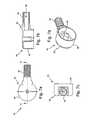
- FIG. 5is an enlarged perspective view of the sensor arrangement for the automatic flushing system shown in FIG. 1 ;
- FIG. 6 ais a perspective view of a first section of a sensor housing of the sensor arrangement shown in FIG. 5 ;
- FIG. 6 bis a bottom view of the first section of a sensor housing of the arrangement shown in FIG. 6 a;
- FIG. 6 cis a sectional view taken along lines 6 c - 6 c of FIG. 6 b;
- FIG. 7 ais a top elevation view of a second section of the sensor housing of the sensor arrangement shown in FIG. 5 ;
- FIG. 7 bis a sectional view taken along lines 7 b - 7 b of FIG. 7 a;
- FIG. 7 cis a side view of the second section of the sensor housing of FIG. 7 a;
- FIG. 7 dis a perspective bottom view of the second section of the sensor housing of FIG. 7 a ;
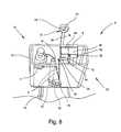
- FIG. 8is a perspective view illustrating a second embodiment of the invention of the automatic flushing system of the invention wherein the sensor arrangement is mounted to the wall above a conventional toilet and the actuator is mounted to a rim of the reservoir tank of a conventional toilet.
- the inventionprovides a first embodiment of an automatic toilet flushing system 10 for a conventional toilet T which has a toilet bowl TB and a reservoir tank 13 .
- the automatic toilet flushing system 10includes an actuator 12 mounted in the reservoir tank 13 and in communication with a sensor 14 , which is mounted into a sidewall of the conventional toilet T.
- the sensor 14may be in communication with the actuator 12 via a wire W or via a transmitted signal (i.e., wireless communication).
- a radio frequency transmittercan be provided in the sensor 14 and a corresponding radio frequency receiver may be provided in the actuator 12 .
- the actuator 12is housed in an actuator box 16 and includes a gear train 18 , a motor 20 having an output shaft 22 , and an external rotating arm 24 having a shaft 26 .
- the output shaft 22 of the motor 20is rotatably connected to the gear train 18
- the external arm 24is rotatably connected to the gear train 18 via shaft 26 .
- a power sourcesuch as a battery 28 , is electrically connected to the motor 20 .
- a signal transmission receiver(not shown) in communication with both the sensor 14 and the motor 20 may be used to receive transmitted signals from the sensor 14 , thus activating and/or deactivating the motor 20 . It is conceivable that the power could be provided via an electric line from an external power source coupled directly to the battery 28 .
- FIGS. 2 and 3show the actuator box 16 of the automatic flushing system 10 having an open end 17 defining a first compartment 32 and a second compartment 34 .
- the first compartment 32 of the actuator box 16can be used to house the battery 28 and a signal transmission receiver for wireless communication (not shown), and the second compartment 34 can be used to house the gear train 18 and the motor 20 .
- the open end 17 of the first compartment 32 of the actuator box 16defines a plurality of holes 33 adapted to receive fasteners.
- the actuator box 16is preferably made of a unitary piece of molded plastic so as to be resistant to water and chemicals normally present in a toilet/bathroom environment.
- the external arm 24is pivotably mounted on the outside of the actuator box 16 , wherein the shaft 26 of the external arm 24 extends through an opening O in a sidewall of the actuator box 16 , thus connecting the external arm 24 to the gear train 18 .
- the output shaft 22 of the motor 20rotates the gear train 18 , thereby pivotably rotating the external arm 24 .
- a first cover 36having a body 38 and defining a plurality of slots 39 is used to cover the first compartment 32 of the actuator box 16 .
- the first cover 36can be attached to the open end 17 of the first compartment 32 of the actuator box 16 via a fastener (not shown) passing through slot 39 defined in the cover body 38 of cover 36 and hole 33 defined in the actuator box 16 .
- the first compartment 32 and the first cover 36fully enclose the power source.
- a second cover 40 having a body 42may be used to cover the second compartment 34 of the actuator box 16 .
- the second cover 40is preferably sealed to the open end 17 of the second compartment 34 of the actuator box 16 by sonic welding.
- a gasket, such as an O-ring 46can be inserted between the cover 40 and the open end 17 of the actuator box 16 to seal the compartment 34 , thus preventing moisture from entering.
- the second compartment 34 and the second cover 40fully enclose the gear train 18 and the motor 20 .
- the gear train 18is used to rotate the external arm 24 of the actuator 12 .
- the external arm 24includes a body 25 , wherein the shaft 26 is defined at one end of the body 25 and extends therefrom, and a tab 27 is defined at an opposite end of the body 25 and extends in a direction opposite that of the shaft 26 .
- the shaft 26 of the body 25 of the external arm 24is keyed to the gear train 18 , and the tab 27 of the body 25 of the external arm 24 is connected to a flapper valve 76 via a bead chain C as particularly shown in FIG. 4 .
- a handle swivel HS co-acting with the tab 27can also be used to connect the external arm 24 to the flapper valve 76 (shown in FIG.
- a sealing arrangement 29is defined between the shaft 26 and the body 25 of the external arm 24 in order to pivotably attach the external arm 24 to the actuator box 16 .
- a gasketsuch as an O-ring (not shown) or cup seal G, may be used to seal the opening in the actuator box 16 around the shaft 26 of the external arm 24 , thus preventing moisture from entering the actuator box 16 .
- a clip 31such as an E-clip defined in the second compartment 34 , may also be used to secure the external arm 24 to the outside of the actuator box 16 .
- the actuator 12includes a battery tray 78 which supports several batteries 28 in first compartment 32 .
- the batteries 28may be disposable or rechargeable.
- the first cover 36 of the first compartment 32includes a thumb screw S used in conjunction with a gasket 44 to seal the first compartment 32 .
- a stabilizing arrangementsuch as the use of a clip, screw and knurled insert represented by elements X and Z can be used to further secure the actuator 12 to the tank reservoir 13 as shown in FIGS. 2 and 3 .
- FIG. 5shows the sensor 14 of the automatic flushing system 10 used to detect when a human body comes within a predetermined distance with respect to a toilet bowl (not shown).
- the sensor 14is preferably located in the manual flush handle hole of a conventional toilet, thus replacing the manual flush handle as shown in FIG. 1 .
- the sensor 14can be located anywhere in the bathroom as long as it can detect a person at the toilet, more about which will be discussed relative to the second embodiment of the invention of FIG. 8 .
- the sensor 14preferably uses ultrasound technology to detect a user near the toilet. By using ultrasound technology, false detection due to moisture, such as steam, is eliminated. Also, ultrasound technology is not sensitive to color and can operate in all shades of light.
- the sensor 14can also utilize magnetic, electrostatic, optical and electromagnetic principles for detection of a person in the vicinity of the sensor 14 . Other types of sensors may be used, such as heat sensors and infrared sensors.
- FIGS. 6 a - 6 c and 7 a - 7 dshow a sensor housing 50 having a body 52 and defining a first section 54 and a second section 56 .
- the housing 50is preferably made of a material that is resistant to chemicals and water, such as a polymeric material.
- the first section 54 of the body 52is preferably tubular shaped and includes a first closed end 58 and a second open end 60 .
- the first section 54 of the body 52defines a plurality of openings 62 , 62 ′, wherein the ultrasound generating source (not shown) can transmit ultrasound waves passing through the opening 62 , and an ultrasound detector (not shown) can receive ultrasound transmissions passing through opening 62 ′, thus detecting a user at the toilet.
- openings 62 and 62 ′can be an infrared transmitter and receiver, respectively. Infrared transmitters and receivers are well known in the art.
- the second section 56 of the body 52 of the sensor housing 50is preferably annular shaped and includes an attached member 64 extending therefrom.
- the second section 56 of the body 52is adapted to rotatably fasten to the second open end 60 of the first section 54 of the body 52 of the sensor housing 50 .
- the member 64 defining a center passageway 66(shown in FIGS. 7 b - 7 d ) is adapted to mount in the flush handle hole of a conventional toilet in a way that is similar to the way a manual flush handle is mounted to a toilet (shown in FIG. 1 ). Referring to FIG.
- the sensor 14can be mounted into the flush handle hole of the toilet T, via a nut N threadably fastened to a threaded portion of the member 64 .
- the sensor 14is electrically connected to the motor 20 in the actuator box 16 via the wire W passing through the center passageway 66 of the member 64 and sandwiched between the first cover 36 and actuator box 16 as shown in FIG. 1 .
- the wire Wshould be thin enough to allow the first cover 36 to seal properly, thus preventing moisture from entering the actuator box 16 .
- grommets or other types of seals or sealantscan be used for the wire W to pass through the actuator box 16 .
- FIG. 8shows a second embodiment of an automatic toilet flushing system 70 that is similar to automatic flushing system 10 .
- a sensor 72includes a sensor housing 74 and a sensor element 75 .
- the sensor element 75can be an infrared sensor that is well known in the art to detect the presence of a user.
- Sensor housing 74preferably is mounted on a wall in close proximity to actuator 12 .
- sensor housing 72may be located anywhere in the bathroom as long as it can detect a user near the toilet.
- the sensor housing 74can house all of the internal components of sensor 14 including a transmitter for wireless communication (not shown), thereby eliminating the need for a physical connection, such as a wire W between the sensor 72 and the actuator 12 .
- the transmittercan transmit a signal from the sensor 72 to a signal transmission receiver (not shown) in the actuator box 16 , for example, by radio frequency transmissions.
- the sensor housing 74can be attached to a wall or an object using mechanical fasteners, adhesive tape or other means known in the art.
- the wire Wcan use male/female connectors to the sensor 72 and the actuator 16 .
- the toilet Tcomprises a toilet bowl TB and a reservoir tank 13 (also referred to as a water chest) located immediately rearwardly of and above the toilet bowl as best shown in FIG. 1 .
- a reservoir tank 13also referred to as a water chest
- wateris allowed to drain from the reservoir tank 13 by the force of gravity directly into the toilet bowl through conventional plumbing connections.
- the toilet Tis generally provided with the flush handle H normally located on the side of the reservoir tank 13 and which operates a flushing mechanism M located within the reservoir tank 13 . As particularly shown in FIG.
- this flushing mechanism Mtypically includes a flapper valve 76 which is located at the lower end of the reservoir tank 13 and which can be opened and closed with respect to a water outlet 78 covered by the flapper valve 76 for releasing water into the toilet bowl.
- a second bead chain 77(shown in FIG. 4 ) is generally used to connect the flapper valve 76 to the flush handle H.
- the manual flush handleis replaced with the sensor 14 of the automatic flushing system 10 . Referring to FIGS.
- the actuator 12is mounted to a ledge of the reservoir tank 13 via a bracket B, and the chain C connects the actuator 12 to the flapper valve 76 (shown best in FIG. 4 ). As shown best in FIG. 4 , one end of the chain C is connected to the handle swivel HS on the external arm 24 and the opposite end of the chain C is connected to the flapper valve 76 .
- the sensor 14 of the embodiment of FIGS. 1 , 6 a - 6 c , and 7 a - 7 dis designed so that sensor housing 50 is mounted in an opening of the reservoir tank 13 which generally receives a manually operated flush handle.
- the sensor housing 50is designed to accommodate various tank designs in the market, such as front handle, side handle and 45° handle designs.
- the first section 54 of the body 52 of the sensor housing 50can be adjusted by rotating the openings 62 , 62 ′ to a position for optimum user detection.
- the sensor 14transmits a signal, such as ultrasound waves or infrared signals, through opening 62 of the sensor housing 50 within a vicinity of a toilet area.
- a signalsuch as ultrasound waves or infrared signals
- the signalis reflected by the body of the person and a receiver (not shown), such as an ultrasound receiver or infrared receiver, will receive a modulated signal through opening 62 ′ thus detecting the presence of the person.
- the sensor 14relays this signal to the actuator 12 via wire W or via wireless transmissions, such as radio frequency transmissions.
- a delay circuitwhich delays the signal for a predetermined time can be used to ensure that there is a person using the toilet T, and not just passing by.
- the waterthen flows out from the reservoir tank 13 into the outlet 78 , thereby flushing the toilet T.
- the motor 20is activated and moves in a reverse direction pivotally moving the pivotal arm 24 from the second position back to the first position, thus closing the flapper valve 76 .
- a timer(not shown) can be used to determine the flush time, which corresponds to the amount of water used for flushing the toilet T.
- sensor 72can detect the presence of a person approaching the toilet.
- Sensor 72also preferably uses infrared technology, but can use any other technology, such as magnetic, electrostatic, ultrasonic and electromagnetic principles, for detection of a person in the vicinity of the sensor 72 .
- the sensor 72is in communication with the actuator 12 via an electrical connector W or via radio frequency transmissions or infrared transmissions (not shown).
- the connector Wcan be partially covered with a cover 94 , such as a channel, to hide the connector W.
- Sensor 72includes housing 74 that is disc-shaped, wherein the housing 74 is preferably mounted above the reservoir tank 13 .
- the sensor housing 74can have a geometric-shaped window, such as rectangular shaped, as shown in FIG. 8 , or circular shaped, not shown. Also, even though not shown, the sensor housing 74 may be rectangular shaped with a rectangular-shaped or circular-shaped window for the sensing detectors.
- the sensor 72can be mounted to a wall or an object using mechanical fasteners, adhesive tape or other means known in the art.
- the automatic flushing system 70 of FIG. 8operates in a similar manner to automatic flushing system 10 of FIG. 1 ; however, the actuator 14 of FIG. 1 does not replace the existing manual flush handle H of a conventional toilet T, thereby allowing optional manual flushing of the toilet T as well as automatic flushing.
- the flush handle Hwould also be connected to the flapper valve 76 preferably via the second bead chain 77 as shown in phantom in FIG. 4 .
- the actuator 12 in the automatic flushing system 70is similar to the automatic flushing system 10 of FIGS. 1 .
- a further embodimentrelates to a method of converting a manual toilet flushing system into an automatic toilet flushing system 10 , 70 .
- This methodinvolves the steps of providing sensor 14 for sensing the approach and departure motion of a user with respect to the toilet T and for generating a signal representative of the approach and departure motion of the user; providing actuator 12 in communication with the sensor 14 , 72 for causing an automatic flushing of the toilet in response to the signal from the sensor 14 , 72 , the actuator 12 having a driven pivotal arm 24 ; and providing a flushing mechanism co-acting with the actuator 12 , wherein the flushing mechanism 10 includes a flapper valve 76 adapted to release water from the reservoir tank 13 , and wherein the pivotal arm 24 of the actuator 12 being connected to the flapper valve 76 for operation of the flapper valve upon the pivotal movement of the pivotal arm.
- the handle swivel HSis provided on the end of the pivotal arm 24 and a connector member, e.g., chain C is provided and connects the handle swivel HS to the flapper valve 76 .
- the methodalso involves providing a tab 27 on the end of the pivotal arm 24 , and a connector member, e.g., chain C is provided and connects the tab to the flapper valve 76 .
- the stepsfurther include providing a first sensor 50 ( FIG. 1 ) configured to be inserted into an opening in the sidewall of the reservoir tank 13 to replace the manually operated handle or providing a second sensor 72 ( FIG. 8 ) configured to be in close proximity to the reservoir tank 13 for optional operation of the flush handle H.
- the stepsstill further include providing a bracket B on the actuator 12 , and mounting the actuator 12 inside the reservoir tank 13 by securing the bracket B to the reservoir tank 13 .
- a related kitfor converting a manually operated toilet flushing system into an automatic toilet flushing system 10 in a toilet T having a reservoir tank 13 and a toilet bowl TB.
- the kitincludes a sensor 14 , 72 for sensing the approach and departure motion of a user with respect to the toilet T and for generating a signal representative of the approach and departure motion of the user; an actuator 12 in communication with the sensor for causing an automatic flushing of the toilet in response to the signal from the sensor, the actuator having a driven pivotal arm; and a flushing mechanism co-acting with the actuator 12 , the flushing mechanism including a flapper valve 76 adapted to release water from the reservoir tank 13 , and the pivotal arm 24 of the actuator 12 being connected to the flapper valve 76 for operation of the flapper valve 76 upon the pivotal movement of the pivotal arm 24 .
- the kitmay include a handle swivel HS for mounting to the pivotal arm 24 and a connector member, e.g., chain C for connecting the handle swivel HS to the flapper valve 76 .
- the kitmay include a tab 27 ( FIG. 1 ) mounted at the end of the pivotal arm 24 and a connector member, e.g., chain C for connecting the tab 27 to the flapper valve 76 .
- the kitmay also include a bracket B for easily attaching the actuator 12 inside the reservoir tank 13 as shown in FIG. 3 , a first sensor 50 configured to be inserted into an opening in the sidewall of the reservoir tank to replace the manually operated handle ( FIG. 1 ); and a second sensor 72 configured to be in close proximity to the reservoir tank for optional operation of the manually operated handle H ( FIG. 8 ).
Landscapes
- Engineering & Computer Science (AREA)
- Aviation & Aerospace Engineering (AREA)
- Health & Medical Sciences (AREA)
- Life Sciences & Earth Sciences (AREA)
- Hydrology & Water Resources (AREA)
- Public Health (AREA)
- Water Supply & Treatment (AREA)
- Sanitary Device For Flush Toilet (AREA)
Abstract
Description
Claims (31)
Priority Applications (1)
| Application Number | Priority Date | Filing Date | Title |
|---|---|---|---|
| US11/789,034US8695125B2 (en) | 2006-04-21 | 2007-04-23 | Automatic actuator to flush toilet |
Applications Claiming Priority (2)
| Application Number | Priority Date | Filing Date | Title |
|---|---|---|---|
| US79391606P | 2006-04-21 | 2006-04-21 | |
| US11/789,034US8695125B2 (en) | 2006-04-21 | 2007-04-23 | Automatic actuator to flush toilet |
Publications (2)
| Publication Number | Publication Date |
|---|---|
| US20080072369A1 US20080072369A1 (en) | 2008-03-27 |
| US8695125B2true US8695125B2 (en) | 2014-04-15 |
Family
ID=39223325
Family Applications (1)
| Application Number | Title | Priority Date | Filing Date |
|---|---|---|---|
| US11/789,034Active2030-01-18US8695125B2 (en) | 2006-04-21 | 2007-04-23 | Automatic actuator to flush toilet |
Country Status (1)
| Country | Link |
|---|---|
| US (1) | US8695125B2 (en) |
Cited By (9)
| Publication number | Priority date | Publication date | Assignee | Title |
|---|---|---|---|---|
| US20140283291A1 (en)* | 2013-03-23 | 2014-09-25 | Robert Austin | Voice Command Flush Module |
| US20150167280A1 (en)* | 2012-12-17 | 2015-06-18 | Fluidmaster, Inc. | Touchless Activation of a Toilet |
| US20180292022A1 (en)* | 2017-04-10 | 2018-10-11 | B/E Aerospace, Inc. | Method and apparatus for controlling a waste outlet of a toilet |
| US10941552B2 (en) | 2018-01-22 | 2021-03-09 | Charles Dylan Grody | Programmable toilet flush initiating, monitoring and management system and method thereof |
| US11208798B2 (en)* | 2018-01-03 | 2021-12-28 | Kohler Co. | System and method for touchless actuation of a toilet |
| US11739513B2 (en) | 2018-01-22 | 2023-08-29 | Hydraze, Inc. | Programmable toilet flush initiating, monitoring and management system and method thereof |
| US11859375B2 (en) | 2009-12-16 | 2024-01-02 | Kohler Co. | Touchless faucet assembly and method of operation |
| US11866922B2 (en) | 2020-01-16 | 2024-01-09 | Hydraze, Inc. | Programmable toilet flush initiating, monitoring and management system and method thereof |
| US12270190B2 (en) | 2018-01-22 | 2025-04-08 | Hydraze, Inc. | Method and apparatus for controlling automatic toilet flushing system |
Families Citing this family (14)
| Publication number | Priority date | Publication date | Assignee | Title |
|---|---|---|---|---|
| US8615821B2 (en) | 2007-05-31 | 2013-12-31 | Zurn Industries, Llc | Actuator having a clutch assembly |
| US9115487B2 (en)* | 2008-07-22 | 2015-08-25 | Advanced Modern Technologies Corporation | Motorized automate/manual push button system |
| ES2752803T3 (en)* | 2008-12-17 | 2020-04-06 | Geberit Service Ab | Device and method for flushing a toilet |
| US8434172B2 (en)* | 2009-04-28 | 2013-05-07 | Masco Canada Limited | Dual flush electronic flush valve |
| DE102009052046A1 (en)* | 2009-11-05 | 2011-05-12 | Airbus Operations Gmbh | Monitoring device for a vacuum toilet |
| US20120317709A1 (en)* | 2011-06-17 | 2012-12-20 | B. O. & M. M. Enterprises, LLC. | Retrofit automatic toilet flush apparatus |
| US8924028B2 (en) | 2011-08-01 | 2014-12-30 | Control Microsystems, Inc. | Battery-powered control valve and operation thereof |
| US8973595B2 (en)* | 2011-08-01 | 2015-03-10 | Control Microsystems, Inc. | Battery-powered control valve and operation thereof |
| CN103806518B (en)* | 2012-11-02 | 2015-09-30 | 科勒公司 | Improved non-contact flushing system and method |
| CN102995727B (en)* | 2012-12-13 | 2014-06-11 | 林江 | Water-saving device for water closet |
| HK1210815A1 (en)* | 2012-12-17 | 2016-05-06 | 福马公司 | Touchless activation of a toilet |
| JP6338050B2 (en)* | 2014-03-19 | 2018-06-06 | Toto株式会社 | Drainage operation device and toilet device equipped with this drainage operation device |
| US20180182218A1 (en)* | 2016-08-17 | 2018-06-28 | Marc Toland | Fire detection system |
| CN112502253A (en)* | 2020-11-23 | 2021-03-16 | 梁龙恩 | External hanging installation-free intelligent induction button equipment for toilet water tank |
Citations (52)
| Publication number | Priority date | Publication date | Assignee | Title |
|---|---|---|---|---|
| US602494A (en)* | 1898-04-19 | Traveler s toilet-case | ||
| US3471868A (en) | 1968-01-25 | 1969-10-14 | Palleon Electronics Ltd | Ultrasonic sensing device for a flushing valve on a plumbing fixture |
| US3482268A (en) | 1965-03-31 | 1969-12-09 | Minoru Fukumitsu | Apparatus for the automatic flushing of toilets |
| US4141091A (en) | 1976-12-10 | 1979-02-27 | Pulvari Charles F | Automated flush system |
| US4225986A (en) | 1979-06-25 | 1980-10-07 | Mauk Eugene M | Water release mechanism |
| US4307923A (en)* | 1978-05-31 | 1981-12-29 | Zeev Raz | Bathroom cabinet |
| US4338690A (en) | 1978-12-01 | 1982-07-13 | Hsieh Jung H | Automatic mechanism for flush and raising toilet seat |
| US4392260A (en) | 1982-07-06 | 1983-07-12 | Bensen Court M | Flushing apparatus with selective quantity control |
| US4485501A (en) | 1983-05-02 | 1984-12-04 | Kloner Irving I | Water saving flush tank mechanism |
| US4575880A (en) | 1984-01-31 | 1986-03-18 | Robert Burgess | Auto-flush system |
| US4707867A (en) | 1985-12-18 | 1987-11-24 | F.M. Valve Manufacturing Co., Ltd. | Toilet-flushing control apparatus |
| US4941215A (en) | 1989-01-19 | 1990-07-17 | Liu Su Haw | Automatic flushing device for a flush toilet |
| US5003643A (en)* | 1989-11-14 | 1991-04-02 | Wilson Chung | Flush controller for a toilet bowl |
| US5036553A (en) | 1990-06-26 | 1991-08-06 | Sanderson Dilworth D | Fully automatic toilet system |
| US5187818A (en) | 1991-05-14 | 1993-02-23 | Barrett Sr John P | Flushing system for a water closet |
| US5187816A (en) | 1991-11-20 | 1993-02-23 | Chen Chi Electro Chemical Co., Ltd. | Automatic flushing device |
| US5228146A (en)* | 1991-12-26 | 1993-07-20 | Steve Martell | Flushing device for toilet |
| US5313674A (en) | 1991-12-13 | 1994-05-24 | Sing Chiang | Flushing device |
| US5400446A (en)* | 1992-01-22 | 1995-03-28 | Kohler Co. | Seat cover actuated flushing mechanism for toilet |
| US5448784A (en) | 1990-11-13 | 1995-09-12 | Smiley; Everett J. | Urinal assembly and electrically actuated valve for same |
| US5455971A (en) | 1990-11-29 | 1995-10-10 | Inax Corporation | Water-closet bowl automatic flushing system |
| US5469586A (en) | 1988-03-02 | 1995-11-28 | Toto Ltd. | Toilet bowl flushing device |
| US5482250A (en) | 1993-10-14 | 1996-01-09 | Uro Denshi Kogyo Kabushiki Kaisha | Automatic flushing device |
| US5548119A (en)* | 1995-04-25 | 1996-08-20 | Sloan Valve Company | Toilet room sensor assembly |
| US5603127A (en) | 1992-03-25 | 1997-02-18 | Veal; Bennie N. | Auto flush for tank toilet |
| US5855027A (en) | 1998-05-28 | 1999-01-05 | Macedo; Joseph A. | Automatic bathroom door and toilet flushing system |
| US5901384A (en) | 1997-04-14 | 1999-05-11 | Sim; Jae K. | Toilet assembly having automatic flushing system |
| US5950983A (en) | 1993-08-23 | 1999-09-14 | Sloan Valve Company | Infrared detector with beam path adjustment |
| US6056261A (en) | 1997-10-31 | 2000-05-02 | Sloan Valve Company | Sensor-operated solenoid direct drive flush valve |
| US6202227B1 (en) | 1999-03-05 | 2001-03-20 | John Gurowitz | Automatic toilet flushing system |
| US6206340B1 (en) | 1997-07-18 | 2001-03-27 | Kohler Company | Radar devices for low power applications and bathroom fixtures |
| US6212697B1 (en) | 1999-09-07 | 2001-04-10 | Arichell Technologies, Inc. | Automatic flusher with bi-modal sensitivity pattern |
| US6237165B1 (en) | 1999-03-22 | 2001-05-29 | E. Flush Tech Co., Ltd. | Electromagnetic control device for flush tank |
| US6263519B1 (en) | 2000-04-07 | 2001-07-24 | Arichell Technologies, Inc. | Automatic tank-type flusher |
| US20020029412A1 (en) | 2000-04-06 | 2002-03-14 | Veal Bennie N. | Automatic flushing and seat raising arrangements for toilets |
| US20020092090A1 (en) | 2001-01-18 | 2002-07-18 | Johnson Dwight N. | Flush controller |
| US20020162166A1 (en) | 2001-03-06 | 2002-11-07 | Saar David A. | Flush control |
| US20030019022A1 (en) | 2001-07-27 | 2003-01-30 | Wilson John R. | Automatically operated handle-type flush valve |
| US6513787B1 (en) | 1998-05-04 | 2003-02-04 | American Standard International Inc. | Touchless fluid supply interface and apparatus |
| US20030074725A1 (en) | 2001-10-24 | 2003-04-24 | Pino Wilton J. | Water closet flushing system |
| US20030102450A1 (en) | 2001-12-04 | 2003-06-05 | Parsons Natan E. | Adaptive object-sensing system for automatic flusher |
| US20030102449A1 (en) | 2001-12-04 | 2003-06-05 | Parsons Natan E. | Automatic flow controller employing energy-conservation mode |
| US20030102448A1 (en) | 2001-12-04 | 2003-06-05 | Parsons Natan E. | Assembly of solenoid-controlled pilot-operated valve |
| US20030116736A1 (en) | 2001-12-21 | 2003-06-26 | Muderlak Kenneth J. | Automatic flush valve actuation apparatus |
| US6598245B2 (en) | 2001-01-19 | 2003-07-29 | San-Ei Faucet Mfg. Co., Ltd | Automatic water feed method in lavatory and automatic water feed mechanism in lavatory |
| US20040040079A1 (en) | 2002-08-27 | 2004-03-04 | Snyder Jonathan W. | Automatically operated handle-type flush valve |
| US20040068784A1 (en) | 2002-10-12 | 2004-04-15 | Technical Concepts, Llc. | Automatic flushing actuator for tank style toilet |
| US20040154087A1 (en) | 2003-02-07 | 2004-08-12 | Hogues Herman Holt | Cordless pedal flush system for a tank-type toilet |
| US6860282B2 (en) | 2001-10-06 | 2005-03-01 | Arichell Technologies, Inc. | System and method for converting manually-operated flush valve |
| US20050076425A1 (en)* | 2003-10-14 | 2005-04-14 | Contadini Carl D. | Tank toilet with autoflusher |
| US20060277674A1 (en) | 2005-06-08 | 2006-12-14 | Oakes Samuel W Jr | Handle assembly for a toilet with a rotating sensor assembly |
| US20080196151A1 (en) | 2005-06-08 | 2008-08-21 | Waterbury Companies, Inc. | Handle Assembly For a Toilet With a Rotating Sensor Assembly |
- 2007
- 2007-04-23USUS11/789,034patent/US8695125B2/enactiveActive
Patent Citations (58)
| Publication number | Priority date | Publication date | Assignee | Title |
|---|---|---|---|---|
| US602494A (en)* | 1898-04-19 | Traveler s toilet-case | ||
| US3482268A (en) | 1965-03-31 | 1969-12-09 | Minoru Fukumitsu | Apparatus for the automatic flushing of toilets |
| US3471868A (en) | 1968-01-25 | 1969-10-14 | Palleon Electronics Ltd | Ultrasonic sensing device for a flushing valve on a plumbing fixture |
| US4141091A (en) | 1976-12-10 | 1979-02-27 | Pulvari Charles F | Automated flush system |
| US4307923A (en)* | 1978-05-31 | 1981-12-29 | Zeev Raz | Bathroom cabinet |
| US4338690A (en) | 1978-12-01 | 1982-07-13 | Hsieh Jung H | Automatic mechanism for flush and raising toilet seat |
| US4225986A (en) | 1979-06-25 | 1980-10-07 | Mauk Eugene M | Water release mechanism |
| US4392260A (en) | 1982-07-06 | 1983-07-12 | Bensen Court M | Flushing apparatus with selective quantity control |
| US4485501A (en) | 1983-05-02 | 1984-12-04 | Kloner Irving I | Water saving flush tank mechanism |
| US4575880A (en) | 1984-01-31 | 1986-03-18 | Robert Burgess | Auto-flush system |
| US4707867A (en) | 1985-12-18 | 1987-11-24 | F.M. Valve Manufacturing Co., Ltd. | Toilet-flushing control apparatus |
| US5469586A (en) | 1988-03-02 | 1995-11-28 | Toto Ltd. | Toilet bowl flushing device |
| US4941215A (en) | 1989-01-19 | 1990-07-17 | Liu Su Haw | Automatic flushing device for a flush toilet |
| US5003643A (en)* | 1989-11-14 | 1991-04-02 | Wilson Chung | Flush controller for a toilet bowl |
| US5036553A (en) | 1990-06-26 | 1991-08-06 | Sanderson Dilworth D | Fully automatic toilet system |
| US5448784A (en) | 1990-11-13 | 1995-09-12 | Smiley; Everett J. | Urinal assembly and electrically actuated valve for same |
| US5455971A (en) | 1990-11-29 | 1995-10-10 | Inax Corporation | Water-closet bowl automatic flushing system |
| US5187818A (en) | 1991-05-14 | 1993-02-23 | Barrett Sr John P | Flushing system for a water closet |
| US5187816A (en) | 1991-11-20 | 1993-02-23 | Chen Chi Electro Chemical Co., Ltd. | Automatic flushing device |
| US5313674A (en) | 1991-12-13 | 1994-05-24 | Sing Chiang | Flushing device |
| US5228146A (en)* | 1991-12-26 | 1993-07-20 | Steve Martell | Flushing device for toilet |
| US5400446A (en)* | 1992-01-22 | 1995-03-28 | Kohler Co. | Seat cover actuated flushing mechanism for toilet |
| US5603127A (en) | 1992-03-25 | 1997-02-18 | Veal; Bennie N. | Auto flush for tank toilet |
| US6161814A (en) | 1993-08-23 | 2000-12-19 | Sloan Valve Company | Infrared detector with beam path adjustment |
| US5950983A (en) | 1993-08-23 | 1999-09-14 | Sloan Valve Company | Infrared detector with beam path adjustment |
| US5482250A (en) | 1993-10-14 | 1996-01-09 | Uro Denshi Kogyo Kabushiki Kaisha | Automatic flushing device |
| US5548119A (en)* | 1995-04-25 | 1996-08-20 | Sloan Valve Company | Toilet room sensor assembly |
| US5901384A (en) | 1997-04-14 | 1999-05-11 | Sim; Jae K. | Toilet assembly having automatic flushing system |
| US6206340B1 (en) | 1997-07-18 | 2001-03-27 | Kohler Company | Radar devices for low power applications and bathroom fixtures |
| US6568655B2 (en) | 1997-07-18 | 2003-05-27 | Kohler Company | Radar devices for low power applications and bathroom fixtures |
| US6056261A (en) | 1997-10-31 | 2000-05-02 | Sloan Valve Company | Sensor-operated solenoid direct drive flush valve |
| US6513787B1 (en) | 1998-05-04 | 2003-02-04 | American Standard International Inc. | Touchless fluid supply interface and apparatus |
| US5855027A (en) | 1998-05-28 | 1999-01-05 | Macedo; Joseph A. | Automatic bathroom door and toilet flushing system |
| US6202227B1 (en) | 1999-03-05 | 2001-03-20 | John Gurowitz | Automatic toilet flushing system |
| US6237165B1 (en) | 1999-03-22 | 2001-05-29 | E. Flush Tech Co., Ltd. | Electromagnetic control device for flush tank |
| US6212697B1 (en) | 1999-09-07 | 2001-04-10 | Arichell Technologies, Inc. | Automatic flusher with bi-modal sensitivity pattern |
| US20020029412A1 (en) | 2000-04-06 | 2002-03-14 | Veal Bennie N. | Automatic flushing and seat raising arrangements for toilets |
| US6618864B2 (en) | 2000-04-06 | 2003-09-16 | Bennie N Veal | Automatic flushing and seat raising arrangements for toilets |
| US6263519B1 (en) | 2000-04-07 | 2001-07-24 | Arichell Technologies, Inc. | Automatic tank-type flusher |
| US6499152B2 (en) | 2001-01-18 | 2002-12-31 | Geberit Technik Ag | Flush controller |
| US20020092090A1 (en) | 2001-01-18 | 2002-07-18 | Johnson Dwight N. | Flush controller |
| US6598245B2 (en) | 2001-01-19 | 2003-07-29 | San-Ei Faucet Mfg. Co., Ltd | Automatic water feed method in lavatory and automatic water feed mechanism in lavatory |
| US20020162166A1 (en) | 2001-03-06 | 2002-11-07 | Saar David A. | Flush control |
| US6560790B2 (en) | 2001-03-06 | 2003-05-13 | Geberit Technik Ag | Flush control |
| US20030019022A1 (en) | 2001-07-27 | 2003-01-30 | Wilson John R. | Automatically operated handle-type flush valve |
| US6860282B2 (en) | 2001-10-06 | 2005-03-01 | Arichell Technologies, Inc. | System and method for converting manually-operated flush valve |
| US20030074725A1 (en) | 2001-10-24 | 2003-04-24 | Pino Wilton J. | Water closet flushing system |
| US20030102448A1 (en) | 2001-12-04 | 2003-06-05 | Parsons Natan E. | Assembly of solenoid-controlled pilot-operated valve |
| US6619614B2 (en) | 2001-12-04 | 2003-09-16 | Arichell Technologies, Inc. | Automatic flow controller employing energy-conservation mode |
| US20030102449A1 (en) | 2001-12-04 | 2003-06-05 | Parsons Natan E. | Automatic flow controller employing energy-conservation mode |
| US20030102450A1 (en) | 2001-12-04 | 2003-06-05 | Parsons Natan E. | Adaptive object-sensing system for automatic flusher |
| US20030116736A1 (en) | 2001-12-21 | 2003-06-26 | Muderlak Kenneth J. | Automatic flush valve actuation apparatus |
| US20040040079A1 (en) | 2002-08-27 | 2004-03-04 | Snyder Jonathan W. | Automatically operated handle-type flush valve |
| US20040068784A1 (en) | 2002-10-12 | 2004-04-15 | Technical Concepts, Llc. | Automatic flushing actuator for tank style toilet |
| US20040154087A1 (en) | 2003-02-07 | 2004-08-12 | Hogues Herman Holt | Cordless pedal flush system for a tank-type toilet |
| US20050076425A1 (en)* | 2003-10-14 | 2005-04-14 | Contadini Carl D. | Tank toilet with autoflusher |
| US20060277674A1 (en) | 2005-06-08 | 2006-12-14 | Oakes Samuel W Jr | Handle assembly for a toilet with a rotating sensor assembly |
| US20080196151A1 (en) | 2005-06-08 | 2008-08-21 | Waterbury Companies, Inc. | Handle Assembly For a Toilet With a Rotating Sensor Assembly |
Cited By (14)
| Publication number | Priority date | Publication date | Assignee | Title |
|---|---|---|---|---|
| US11859375B2 (en) | 2009-12-16 | 2024-01-02 | Kohler Co. | Touchless faucet assembly and method of operation |
| US20150167280A1 (en)* | 2012-12-17 | 2015-06-18 | Fluidmaster, Inc. | Touchless Activation of a Toilet |
| US9428897B2 (en)* | 2012-12-17 | 2016-08-30 | Fluidmaster, Inc. | Touchless activation of a toilet |
| US20140283291A1 (en)* | 2013-03-23 | 2014-09-25 | Robert Austin | Voice Command Flush Module |
| US20180292022A1 (en)* | 2017-04-10 | 2018-10-11 | B/E Aerospace, Inc. | Method and apparatus for controlling a waste outlet of a toilet |
| US10501923B2 (en)* | 2017-04-10 | 2019-12-10 | B/E Aerospace, Inc. | Method and apparatus for controlling a waste outlet of a toilet |
| US11208798B2 (en)* | 2018-01-03 | 2021-12-28 | Kohler Co. | System and method for touchless actuation of a toilet |
| US12065817B2 (en) | 2018-01-03 | 2024-08-20 | Kohler Co. | System and method for touchless actuation of a toilet |
| US11739513B2 (en) | 2018-01-22 | 2023-08-29 | Hydraze, Inc. | Programmable toilet flush initiating, monitoring and management system and method thereof |
| US10941552B2 (en) | 2018-01-22 | 2021-03-09 | Charles Dylan Grody | Programmable toilet flush initiating, monitoring and management system and method thereof |
| US12139901B2 (en) | 2018-01-22 | 2024-11-12 | Hydraze, Inc. | Programmable toilet flush initiating, monitoring and management system and method thereof |
| US12270190B2 (en) | 2018-01-22 | 2025-04-08 | Hydraze, Inc. | Method and apparatus for controlling automatic toilet flushing system |
| US11866922B2 (en) | 2020-01-16 | 2024-01-09 | Hydraze, Inc. | Programmable toilet flush initiating, monitoring and management system and method thereof |
| US12345036B2 (en) | 2020-01-16 | 2025-07-01 | Hydraze, Inc. | Programmable toilet flush initiating, monitoring and management system and method thereof |
Also Published As
| Publication number | Publication date |
|---|---|
| US20080072369A1 (en) | 2008-03-27 |
Similar Documents
| Publication | Publication Date | Title |
|---|---|---|
| US8695125B2 (en) | Automatic actuator to flush toilet | |
| US8615821B2 (en) | Actuator having a clutch assembly | |
| US7032256B2 (en) | Tank toilet with autoflusher | |
| US7681860B2 (en) | Automate fluid flow control system | |
| US20120068613A1 (en) | Motion detector night light for toilet bowl | |
| US20020029412A1 (en) | Automatic flushing and seat raising arrangements for toilets | |
| AU2018201578B2 (en) | Concealed Wall mounted folding urinal | |
| WO2006042053A2 (en) | Intelligent flow control unit and water management system | |
| JPH06207682A (en) | Automatic flow controller | |
| US20180313073A1 (en) | Adjustable sensor device for a plumbing fixture | |
| US6643852B1 (en) | Automated induction toilet bowl seat lift system | |
| WO2006133454A2 (en) | Handle assembly for a toilet with a rotating sensor assembly | |
| US20230272606A1 (en) | Automatic Sanitaryware Assembly and Systems | |
| GB2535649A (en) | Human sensing toilet occupancy detection alarm | |
| US20080196151A1 (en) | Handle Assembly For a Toilet With a Rotating Sensor Assembly | |
| JP3908580B2 (en) | Automatic faucet | |
| TR201707963U (en) | HIDDEN TOILET SYSTEM | |
| JPH0421900Y2 (en) | ||
| KR20210087692A (en) | Smart automatic flush toilet construction | |
| US11467315B2 (en) | Detection range specification member for human body detection sensor and toilet | |
| CN110185107B (en) | Photoelectric sensing intelligent toilet | |
| KR20000018919A (en) | Device for automatic controlling of water supply valve | |
| JPH0447507B2 (en) | ||
| JP2025118096A (en) | Drainage pipe joint units and toilet systems | |
| WO2024030071A1 (en) | A contactless flushing system and a method of installation of a flushing system |
Legal Events
| Date | Code | Title | Description |
|---|---|---|---|
| AS | Assignment | Owner name:ZURN INDUCTRIES LLC, PENNSYLVANIA Free format text:ASSIGNMENT OF ASSIGNORS INTEREST;ASSIGNOR:ZURN INDUSTRIES, INC.;REEL/FRAME:019644/0794 Effective date:20070709 Owner name:ZURN INDUCTRIES LLC,PENNSYLVANIA Free format text:ASSIGNMENT OF ASSIGNORS INTEREST;ASSIGNOR:ZURN INDUSTRIES, INC.;REEL/FRAME:019644/0794 Effective date:20070709 | |
| AS | Assignment | Owner name:ZURN INDUSTRIES, LLC, PENNSYLVANIA Free format text:ASSIGNMENT OF ASSIGNORS INTEREST;ASSIGNORS:FUNARI, MICHAEL A.;PHILLIPS, JEFFREY T.;VANHOY, BRIAN;AND OTHERS;REEL/FRAME:020256/0398;SIGNING DATES FROM 20070628 TO 20071217 Owner name:ZURN INDUSTRIES, LLC, PENNSYLVANIA Free format text:ASSIGNMENT OF ASSIGNORS INTEREST;ASSIGNORS:FUNARI, MICHAEL A.;PHILLIPS, JEFFREY T.;VANHOY, BRIAN;AND OTHERS;SIGNING DATES FROM 20070628 TO 20071217;REEL/FRAME:020256/0398 | |
| AS | Assignment | Owner name:ZURN INDUSTRIES, LLC, PENNSYLVANIA Free format text:CORRECTIVE ASSIGNMENT TO CORRECT THE TO CORRECT THE SPELLING OF THE ASSIGNEE'S NAME PREVIOUSLY RECORDED ON REEL 019644 FRAME 0794. ASSIGNOR(S) HEREBY CONFIRMS THE ASSIGNMENT FROM ZURN INDUSTRIES, INC. TO ZURN INDUSTRIES, LLC.;ASSIGNOR:ZURN INDUSTRIES, INC.;REEL/FRAME:021407/0918 Effective date:20070709 Owner name:ZURN INDUSTRIES, LLC, PENNSYLVANIA Free format text:CORRECTIVE ASSIGNMENT TO CORRECT THE TO CORRECT THE SPELLING OF THE ASSIGNEE'S NAME PREVIOUSLY RECORDED ON REEL 019644 FRAME 0794. ASSIGNOR(S) HEREBY CONFIRMS THE ASSIGNMENT FROM ZURN INDUSTRIES, INC. TO ZURN INDUSTRIES, LLC;ASSIGNOR:ZURN INDUSTRIES, INC.;REEL/FRAME:021407/0918 Effective date:20070709 | |
| STCF | Information on status: patent grant | Free format text:PATENTED CASE | |
| CC | Certificate of correction | ||
| MAFP | Maintenance fee payment | Free format text:PAYMENT OF MAINTENANCE FEE, 4TH YEAR, LARGE ENTITY (ORIGINAL EVENT CODE: M1551) Year of fee payment:4 | |
| AS | Assignment | Owner name:CREDIT SUISSE AG, CAYMAN ISLANDS BRANCH, AS ADMINISTRATIVE AGENT AND COLLATERAL AGENT, NEW YORK Free format text:SECURITY INTEREST;ASSIGNORS:AMERICAN DRYER LLC;GREEN TURTLE AMERICAS LTD.;WORLD DRYER CORPORATION;AND OTHERS;REEL/FRAME:057893/0121 Effective date:20211004 | |
| MAFP | Maintenance fee payment | Free format text:PAYMENT OF MAINTENANCE FEE, 8TH YEAR, LARGE ENTITY (ORIGINAL EVENT CODE: M1552); ENTITY STATUS OF PATENT OWNER: LARGE ENTITY Year of fee payment:8 | |
| AS | Assignment | Owner name:CREDIT SUISSE AG, CAYMAN ISLANDS BRANCH, AS ADMINISTRATIVE AGENT AND COLLATERAL AGENT, NEW YORK Free format text:PATENT SECURITY AGREEMENT;ASSIGNOR:ZURN WATER, LLC;REEL/FRAME:066293/0879 Effective date:20231215 | |
| AS | Assignment | Owner name:ZURN INDUSTRIES, LLC (F/K/A ZURN INDUSTRIES, INC.), PENNSYLVANIA Free format text:RELEASE OF INTELLECTUAL PROPERTY SECURITY INTEREST IN PATENTS AT REEL 057893, FRAME 0121;ASSIGNOR:CREDIT SUISSE AG, CAYMAN ISLANDS BRANCH, AS ADMINISTRATIVE AGENT AND COLLATERAL AGENT;REEL/FRAME:066067/0937 Effective date:20231215 | |
| AS | Assignment | Owner name:ZURN WATER, LLC, WISCONSIN Free format text:ASSIGNMENT OF ASSIGNORS INTEREST;ASSIGNOR:ZURN INDUSTRIES, LLC;REEL/FRAME:066337/0918 Effective date:20231208 Owner name:ZURN INDUSTRIES, LLC, WISCONSIN Free format text:CONVERSION;ASSIGNOR:ZURN INDUSTRIES, LLC;REEL/FRAME:066336/0603 Effective date:20231025 |