US8694200B2 - Apparatus and method for advice provision and driving condition diagnosis - Google Patents
Apparatus and method for advice provision and driving condition diagnosisDownload PDFInfo
- Publication number
- US8694200B2 US8694200B2US12/533,142US53314209AUS8694200B2US 8694200 B2US8694200 B2US 8694200B2US 53314209 AUS53314209 AUS 53314209AUS 8694200 B2US8694200 B2US 8694200B2
- Authority
- US
- United States
- Prior art keywords
- advice
- travel
- vehicle
- diagnosis result
- travel section
- Prior art date
- Legal status (The legal status is an assumption and is not a legal conclusion. Google has not performed a legal analysis and makes no representation as to the accuracy of the status listed.)
- Active, expires
Links
Images


Classifications
- B—PERFORMING OPERATIONS; TRANSPORTING
- B60—VEHICLES IN GENERAL
- B60W—CONJOINT CONTROL OF VEHICLE SUB-UNITS OF DIFFERENT TYPE OR DIFFERENT FUNCTION; CONTROL SYSTEMS SPECIALLY ADAPTED FOR HYBRID VEHICLES; ROAD VEHICLE DRIVE CONTROL SYSTEMS FOR PURPOSES NOT RELATED TO THE CONTROL OF A PARTICULAR SUB-UNIT
- B60W50/00—Details of control systems for road vehicle drive control not related to the control of a particular sub-unit, e.g. process diagnostic or vehicle driver interfaces
- B60W50/0098—Details of control systems ensuring comfort, safety or stability not otherwise provided for
Definitions
- the present disclosuregenerally relates to an advice provision apparatus and a driving condition diagnosis system for advice provision for the driver of a vehicle based on a diagnosis of driving conditions.
- an apparatus disclosed in Japanese patent document JP-A-2000-247162notifies the driver of diagnosis and evaluation results on multiple diagnosis items based on the detection of the driving conditions and comparison of the detected conditions with standard values.
- diagnosis/evaluation accuracy of the driving conditionssome diagnosis items can hardly be diagnosed appropriately in a quantitative manner (i.e., an absolute assessment).
- the fuel mileage smaller than a certain standard value in a specific sectiondoes not necessarily means that the driving condition in that section is better than the other sections. That is, in other words, the smaller fuel mileage in an expressway, which is usually smaller than the fuel mileage in a local road, should not automatically be diagnosed that the vehicle is in a good driving condition, if, for example, the fuel mileage is not smaller than the average fuel mileage calculated from daily travels of the same expressway section due to over-acceleration or the like. In that case, the driving conditions in the target section may better be diagnosed negatively.
- the present inventionprovides a driving advice provision apparatus that yields an appropriately accurate diagnosis in a course of advice provision based on the diagnosis of driving conditions.
- the driving advice provision apparatusincludes: a vehicle information acquisition unit for acquiring vehicle information that represents a condition of a vehicle; a diagnosis unit for diagnosing a driving condition of the vehicle based on the vehicle information acquired by the vehicle information acquisition unit; an advice generation unit for generating an advice to be provided for a driver of the vehicle based on a diagnosis result by the driving diagnosis unit; and an advice notification unit for notifying the advice for the driver of the vehicle generated by the advice generation unit.
- the diagnosis unit of the driving advice provision apparatusdiagnoses the driving condition of a target travel section by (a) calculating the driving condition of the vehicle for each of travel sections and (b) comparing the calculated driving condition of the target travel section with the calculated driving conditions of other travel sections.
- the driving condition in the target travel sectionmay be diagnosed as being worsened. If, conversely, the driving condition in the target travel section is determined as better in comparison to the driving condition in the other travel section, the driving condition in the target travel section may be diagnosed as being better.
- the driving condition relatively worsened in the target section than the other sectionleads to the worsened diagnosis result, and the driving condition relatively improved in the target section than the other section leads to the better diagnosis result.
- a driving condition diagnosis apparatusincludes: a vehicle information acquisition unit for acquiring vehicle information that represents a condition of a vehicle; and a diagnosis unit for diagnosing a driving condition of the vehicle based on the vehicle information acquired by the vehicle information acquisition unit.
- the diagnosis unit of the driving condition diagnosis apparatusdiagnoses the driving condition of a target travel section by (a) calculating the driving condition of the vehicle for each of travel sections and (b) comparing the calculated driving condition of the target travel section with the calculated driving conditions of other travel sections.
- the driving condition diagnosis apparatusyields the same advantageous effects as the driving advice provision apparatus described above, due to the same operation scheme.
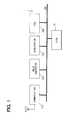
- FIG. 1is a block diagram of a driving diagnosis system having an advice provision apparatus in an embodiment of the present disclosure
- FIG. 2is a detailed block diagram of the advice provision apparatus in the embodiment of the present disclosure
- FIG. 3is a time chart of diagnosis timing of driving conditions and advice generation timing in the embodiment of the present disclosure
- FIG. 4is a diagram of equations of diagnosis calculation in the embodiment of the present disclosure.
- FIG. 5is a diagram of information regarding a relation between vehicle speeds and thresholds of accelerator opening in the embodiment of the present disclosure
- FIG. 6is a flowchart of advice generation processing executed in a control circuit in the embodiment of the present disclosure
- FIG. 7is an illustration of a screen displaying a diagnosis result of the driving condition in the embodiment of the present disclosure.
- FIG. 8is a time chart of advice provision timing in a modification example of the embodiment.
- FIG. 1is a block diagram of a driving diagnosis system 1 having an advice provision an advice provision apparatus 10 of the present disclosure.
- the advice provision apparatus 10is connected with a vehicle local area network 200 .
- the network 200has other components such as, for example, a wide area communication unit 210 , a speed pulse generator 220 , an acceleration sensor 230 and a fuel quantity detection sensor 240 connected thereto.
- various sensors for detecting the condition of the vehicleare connected with to the vehicle local area network 200 .
- the wide area communication unit 210receives information through a radio beacon, a light beacon or the like, and transmits information therethrough.
- the transmitted and received informationincludes, for example, traffic congestion information from VICS information service (Vehicle Information and Communication Service (Registered Trademark) implemented in Japan) together with other information such as vehicle information, user information and the like.
- VICS information serviceVehicle Information and Communication Service (Registered Trademark) implemented in Japan) together with other information such as vehicle information, user information and the like.
- the beaconsare disposed along the road for reception and transmission of the information from the communication unit 210 .
- the speed pulse generator 220generates a pulse signal according to the speed of the vehicle.
- the acceleration sensor 230outputs a signal according to the acceleration of the vehicle.
- the fuel quantity detection sensor 240outputs a signal according to the fuel quantity in the fuel tank.
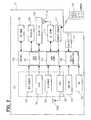
- FIG. 2is a detailed block diagram of the advice provision apparatus 10 .
- the advice provision apparatus 10includes a position sensor 101 , a map database 106 , an operation switch group 107 , an external memory 108 , a display unit 109 , a voice I/O unit 110 , a Bluetooth communication unit (hereinafter designated as a BT unit) 111 , a remote control sensor 112 , a vehicle interface (hereinafter designated as a vehicle I/F) 113 , and a the control circuit 115 which exerts total control of those components.
- a BT unitBluetooth communication unit
- a remote control sensor 112a remote control sensor 112
- vehicle interfacehereinafter designated as a vehicle I/F
- the control circuit 115which exerts total control of those components.
- the position sensor 101is a sensor group to detect the current position and the azimuth (the direction of movement) of the vehicle which has the advice provision apparatus 10 , and is equipped with a geomagnetism sensor 102 , a gyroscope 103 , a distance sensor 104 , and a GPS receiver 105 .
- the GPS receiver 105receives a radio wave from GPS (Global Positioning System) satellites through a GPS antenna 105 a , and detects the position, the azimuth (the direction of movement/travel), the speed of the vehicle and the like.
- GPSGlobal Positioning System
- the geomagnetism sensor 102is an azimuth sensor which uses a semiconductor, and detects geomagnetism of the earth in a north-south direction for determining the azimuth (the direction of movement).
- the gyroscope 103is a sensor for detecting the angular speed (the azimuth variation) of the vehicle, and outputs a detection signal according to the angular speed of the rotating motion of the vehicle.
- the distance sensor 104detects a travel distance based on the acceleration in the front-rear direction of the vehicle and other information.
- the map database 106stores map data.
- the map dataincludes link data which represents a road, node data which represents an intersection, and so-called mapping matching to improve the precision of a specified position, as well as mark data representing facilities, image data for displaying navigation screen, voice data for providing voice guidance.
- the operation switch group 107is an input operation panel that is integrally formed with the display unit 109 , having a touch panel on the display screen together with mechanical button type switches arranged around the screen.
- the touch panel and the display unit 109are arranged in a layered manner, and the various methods of sensing the touch such as a pressure sensing method, an electric-induction method, a capacitance method or a combination of those methods may be employed for the touch sensing method of the touch panel.
- the external memory 108stores various programs executed by the circuit 115 as well as a calculation result of the control circuit 115 and the like.
- the display unit 109uses a liquid crystal color display unit or the like for displaying the image of diagnosis results, a map, a searched route, a TV program, a DVD image and the like as well as displaying button images when the screen of the display unit 109 serves as a touch panel as a part of the operation switch group 107 .
- the voice I/O unit 110provides a sound/voice guidance by outputting the sound/voice of the route guide, and converts user's voice from a microphone to electric signals for voice recognition and other purposes, that is, for outputting recognition results to the control circuit 115 .
- the BT unit 111is a component to wirelessly communicate with peripheral equipment (based on a Bluetooth standard).
- the remote control sensor 112receives signals of radio wave and infrared rays from a remote controller 120 which is operated by the user, and inputs a reception result to the control circuit 115 .
- the useris enabled, by operating the remote controller 120 , to operate the apparatus 1 from a remote position in the same manner as he/she operates the operation switch group 107 .
- the vehicle I/F 113receives signals from the various sensors in the vehicle (e.g., the speed pulse generator 220 , the acceleration sensor 230 , the fuel quantity detection sensor 240 and the like in FIG. 1 ) and inputs those signals to the control circuit 115 .
- the vehiclemay have other sensors such as, for example, an accelerator sensor, a throttle position sensor, a brake sensor, a steering angle sensor, an inter-vehicle distance sensor, an image sensor, a turn signal sensor, an illumination sensor and the like (not shown in the drawing).
- the control circuit 115is equipped with a driving diagnostic information generation unit 151 , a diagnostic information comparison unit 153 , and an advice generation unit 155 .
- the driving diagnostic information generation unit 151receives signals, through the vehicle I/F 113 , from the speed pulse generator 220 , the acceleration sensor 230 , the fuel quantity detection sensor 240 , for example, that is, it acquires a vehicle condition, and then generates diagnostic information (i.e., a diagnosis result). Further, the driving diagnostic information generation unit 151 calculates an information acquisition time based on the time data included in the GPS signal from the GPS satellites. Furthermore, in the present embodiment, the driving diagnostic information generation unit 151 performs a driving condition diagnosis for a unit of travel section that has a predetermined travel distance. The details of the diagnosis are described later.
- the diagnostic information comparison unit 153compares diagnosis results from each of the travel sections. More specifically, it compares a diagnosis result of the previous travel section with a diagnosis result from a current travel section.
- the advice generation unit 155generates an advice to be provided for the driver of the vehicle, based on the diagnostic information generated by the driving diagnostic information generation unit 151 and/or a comparison result by the diagnostic information comparison unit 153 .
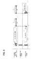
- FIG. 3is a time chart which shows the diagnosis timing of the driving condition and the generation timing of the advice.
- the first rowshows ON and OFF condition of the accessories switch (ACC) of the vehicle.
- the second rowshows travel and stop of the vehicle. That is, each of sections ( 1 ) to ( 6 ) shows a travel section of the vehicle with the vehicle speed greater than 0 km/h.
- the other portion of the chartrepresents stopping of the vehicle, with the vehicle speed equal to 0 km/h.
- the numbers in each of the sectionindicates a travel distance of the vehicle in each of those sections.
- the third rowshows the diagnosis timing of the driving condition.
- a diagnosisis performed for a unit section, or for an evaluation section. More practically, the travel of the vehicle is grasped by using the unit section, which is defined by a start point having a cumulative travel distance of 0 km and an end point where the vehicle stops for the first time after the cumulative travel distance exceeding 1.6 km.
- the threshold distance of 1.6 kmis employed based on a statistics of a short travel, that is, a travel to a nearest store or the like.
- the spot where the vehicle starts the travel after turning on of the ACC switchi.e., the start point of section ( 1 )
- the first stop at the cumulative distance of 0.8 kmdoes not exceed the threshold of 1.6 km, thereby making the spot of the first stop (i.e., the end point of section ( 1 )) not eligible as the end point of an evaluation section.
- the end point of section ( 2 )is not eligible for being an end point of an evaluation section, due to the cumulative travel distance of 1.5 km.
- the end point of section ( 3 ) with the cumulative travel distance of 2.2 kmthen satisfies the end point condition of the evaluation section, that is, exceeding the threshold of 1.6 km.
- the end point of section ( 3 )is the first stop after exceeding the threshold of 1.6 km. Therefore, the first evaluation section starts at the start point of section ( 1 ), and ends at the end point of section ( 3 ).
- the diagnosis timing of the first evaluation sectionis set at the end point of the section ( 3 ). This diagnosis timing is designated as a timing A in FIG. 3 .
- the next evaluation sectionthat is, the second evaluation section, is then defined as a section starting at the end point of section ( 3 ) and ending at the end point of section ( 5 ).
- the diagnosis timing of the second evaluation sectionis set at the end point of section ( 5 ).
- the diagnosis timing of the second evaluation sectionis designated as a timing B.
- the fourth rowshows an advice generation timing (the execution timing of the advice generation processing).
- a diagnosis result in the previous evaluation section and a diagnosis result in the current evaluation sectionare compared for a comparative evaluation of the current section, and an advice based on the comparative evaluation is generated.
- the details of the evaluationare described later with reference to FIG. 5 . Therefore, at the end point of the first evaluation section, no advice is generated due to the non-existence of the previous evaluation section.
- the diagnosis result of the first evaluation section and the diagnosis result of the second evaluation sectionare compared with each other, and the an advice is generated based on the comparative evaluation of the diagnosis result of the second evaluation section.
- FIG. 4is a diagram of diagnosis contents.
- the diagramshows five diagnosis items, that is, an eco switch use rate, an eco lamp lit rate, a mis-geared rate, a mode selection rate, and an over-accel rate.
- diagnosis itemsthat is, an eco switch use rate, an eco lamp lit rate, a mis-geared rate, a mode selection rate, and an over-accel rate.
- all of the five itemsare indices of environment and safety related diagnosis represented by a rate of cumulative travel distances.
- the eco switchis a travel mode selection switch that turns on a low fuel consumption travel mode.
- the air-conditioner operation rateis suppressed relative to a normal mode, for example, or a fuel injection amount is decreased for the same stepping stroke of the acceleration pedal, for the purpose of yielding a lower fuel consumption rate.
- the eco lampis an indicator that is turned on when the vehicle is traveling in an economical traveling condition.
- the economical traveling conditionmay include the low fuel consumption condition.
- the “cumulative” valueindicates an accumulation of the subject value after turning on of the ACC switch.
- the suffix (n)represents that the subject value is a value from the current diagnosis
- the suffix (n ⁇ 1)indicates that the subject value is a value from the previous diagnosis.
- the eco switch (SW) use rateis a rate of travel distance with the eco switch turned on in a certain travel section or in a certain travel distance.
- Equation 1(Eco SW use cumulative travel distance (n) ⁇ Eco SW use cumulative travel distance (n ⁇ 1))/(Cumulative travel distance (n)) ⁇ (Cumulative travel distance (n ⁇ 1)) (Equation 1)
- the eco switch use cumulative travel distanceis a cumulative travel distance of the vehicle with the eco switch turned on (i.e., pressed-down).
- the equation 1is described with reference to the time chart in FIG. 3 .
- the diagnosis value of the previous evaluation sectionis set as 0, and the description is focused on the diagnosis timing B.
- the numerator of the equation 1is calculated by subtracting, from an eco switch use (i.e., turned-on) cumulative travel distance at the timing B, an eco switch use (i.e., turned-on) cumulative travel distance at the timing A. That is, in other words, the travel distance with the eco switch turned on in the second evaluation section is calculated as the numerator.
- the denominator of the equation 1is calculated by subtracting, from a cumulative travel distance at the timing B, a cumulative travel distance at the timing A. That is, in other words, the travel distance of 2.8 km in the second evaluation section is calculated as the denominator.
- the eco lamp lit rateis a rate of travel distance with the eco lamp turned on in a certain travel section.
- Equation 2(Eco lamp cumulative travel distance (n) ⁇ Eco lamp cumulative travel distance (n ⁇ 1))/(Eco lamp diag cumulative travel distance (n)) ⁇ (Eco lamp diag cumulative travel distance (n ⁇ 1)) (Equation 2)
- the eco lamp cumulative travel distanceis a cumulative travel distance of the vehicle with the eco lamp turned on (i.e., the eco lamp being lit).
- the eco lamp diag cumulative travel distanceis a cumulative travel distance with a diagnosis function for determining use of the eco lamp being enabled.
- the numerator of the equation 2is calculated by subtracting, from an eco lamp turned-on cumulative travel distance at the timing B, an eco lamp turned-on cumulative travel distance at the timing A. That is, in other words, the travel distance with the eco lamp turned on in the second evaluation section is calculated as the numerator.
- the denominator of the equation 2is calculated by subtracting, from a cumulative travel distance with the eco lamp turn-on diagnosis at the timing B, a cumulative travel distance with the eco lamp turn-on diagnosis at the timing A. That is, in other words, the cumulative travel distance with the eco lamp turn-on diagnosis exercisable in the second evaluation section is calculated as the denominator.
- the mis-geared rateis a rate of travel distance with a gear selection (i.e., a shift) not matching with an engine torque output.
- the mis-geared cumulative travel distanceis a cumulative travel distance of the vehicle with the gear selection mis-matching with the engine torque output.
- the numerator of the equation 3is calculated by subtracting, from a mis-geared cumulative travel distance at the timing B, a mis-geared cumulative travel distance at the timing A. That is, in other words, the travel distance with the gear selection mis-matching with the engine torque output in the second evaluation section is calculated as the numerator.
- the mode selection rateis a rate of travel distance with a travel mode of the vehicle set to a certain travel mode, such as a sport mode, a power mode and the like in a certain travel section or in a certain travel distance.
- a certain travel modesuch as a sport mode, a power mode and the like in a certain travel section or in a certain travel distance.
- the sport mode/power modeis a travel mode that prioritizes ease of driving, that is, the acceleration response and brake response are improved, for example.
- the sport/power travel modemay improve the acceleration rate.
- Equation 4(Mode-selected cumulative travel distance (n) ⁇ Mode-selected cumulative travel distance (n ⁇ 1))/(Cumulative travel distance (n)) ⁇ (Cumulative travel distance (n ⁇ 1)) (Equation 4)
- the mode-selected cumulative travel distanceis, in this case, a cumulative travel distance of the vehicle with a selection of an eco mode that realizes an economical travel of the vehicle.
- the numerator of the equation 4is calculated by subtracting, from an eco mode used (i.e., selected) cumulative travel distance at the timing B, an eco mode used (i.e., selected) cumulative travel distance at the timing A. That is, in other words, the travel distance with the eco mode selection in the second evaluation section is calculated as the numerator.
- the over-accel rateis a rate of travel distance with an accelerator opening (a stepping amount of the accelerator) exceeding a threshold in a certain travel section or in a certain travel distance.
- the threshold of the accelerationis changed depending on the speed of the vehicle.
- the relationship of the acceleration with the vehicle speedis stored in a table format in the external memory 108 , as illustrated in FIG. 5 . That is, the threshold of the accelerator opening for each of the vehicle speeds of 0 km/h, 5 km/h, 10 km/h, 20 km/h, up to 110 km/h is defined in the table. Further, an engine type and transmission type attribute are added in the table.
- the over-accelerated cumulative travel distanceis a cumulative travel distance of the vehicle with the accelerator opening exceeding a threshold.
- the numerator of the equation 5is calculated by subtracting, from an over-accelerated cumulative travel distance at the timing B, an over-accelerated cumulative travel distance at the timing A. That is, in other words, the travel distance with the accelerator opening exceeding a threshold in the second evaluation section is calculated as the numerator.
- FIG. 6A flowchart in FIG. 6 is then described for illustrating the advice generation processing in the control circuit 115 .
- the advice generation processing of FIG. 6is executed at the advice generation timing as explained in FIG. 3 .
- the process in S 110determines how many times the advice has been generated since turning-on of the accessory (ACC) switch (T th timing: ‘T’ is used as a variable), and then calculates the remainder of the number T after division by 5 (T/5). More practically, if the remainder is equal to 1 is determined.
- the processexecutes the processing of S 120 and S 130 .
- the frequent execution of S 120 /S 130is prevented when the driver has intentionally turned off the eco switch.
- frequent/successive generation of an attention drawing advicewhich may be generated depending on the determination in S 120 /S 130 , is prevented by the calculation of S 110 . Details of the operation scheme are described later.
- the processnotifies that the eco switch is being turned off. More practically, an advice is generated for notifying that the eco switch is turned off, and the advice is displayed on the screen of the display unit 109 .
- the advicemay also be provided by voice from the voice I/O unit 110 .
- the processthen proceeds to S 260 .
- the processdetermines whether the eco switch use rate in the current evaluation section is smaller than 0.8. If the eco switch use rate is smaller than 0.8 (S 130 :YES), the process proceeds to S 200 .
- the processnotifies that the eco switch use rate is low. More practically, an advice is generated for notifying that the eco switch use rate is low, and the advice is displayed on the screen of the display unit 109 . The process then proceeds to S 260 .
- an absolute value of difference between the eco switch use rate in the current diagnosis result and the eco switch use rate in the previous diagnosis result(designated as “eco switch diag value” hereinafter) is compared with an absolute value of difference between the eco lamp lit rate in the current diagnosis result and the eco lamp lit rate in the previous diagnosis result (designated as “eco lamp diag value” hereinafter). If the eco switch diag value is equal to or greater than the eco lamp diag value (S 140 :YES), the process proceeds to S 170 .
- S 170the process proceeds to S 210 when determining that the eco switch use rate in the current evaluation section minus the eco switch use rate in the previous evaluation section is greater than 0 (S 170 :YES).
- S 180the process proceeds to S 220 when determining that the eco switch use rate in the current diagnosis result is not equal to or greater than 0.8 (S 180 :NO), based on the reasoning that the eco switch use rate is low.
- S 150the process determines whether the eco lamp lit rate in the current evaluation section minus the eco lamp lit rate in the previous evaluation section is greater than 0. If the difference is greater than 0 (S 150 :YES), the process proceeds to S 230 .
- S 150determines that the difference is not greater than 0 (S 150 :NO)
- the processproceeds to S 160 .
- the process in S 160determines whether the eco lamp lit rate in the current diagnosis result is greater than 0.8. If the eco lamp lit rate in the current diagnosis result is greater than 0.8 (S 160 :YES), the process proceeds to S 240 .
- S 240the process generates no advice before proceeding to S 260 .
- the processdetermines that the eco lamp lit rate is not greater than 0.8 (S 160 :NO)
- the processproceeds to S 250 , for generating and displaying, on the screen of the display unit 109 , an advice that notifies the driver that the accelerator is opened too much.
- the processthen proceeds to S 260 .
- S 270the process returns to S 110 when determining that the ACC switch is not turned off (S 270 :NO). If, in S 270 , the process determines that the ACC switch is turned off (S 270 :YES), the process concludes itself.
- FIG. 7An example of the screen that displays the diagnosis result of the driving condition is shown in FIG. 7 .
- the screenat least displays user information, an eco level, fuel mileage information, and an advice.
- the user informationis information of a user who is logged in. If no user is logged in, that is, if no user is identified, the screen displays GUEST DRIVER as the user name, indicating that the user is presumed as a guest.
- the eco levelis an index of the “economical” driving habit.
- diagnosis resultssuch as the fuel mileage, the eco switch use rate, the eco lamp lit rate, the mis-geared rate, the mode selection rate, the over-accel rate and the like are totally evaluated, for the purpose of eco level determination.
- the term of evaluationmay be for one minute, for one trip (e.g., a term between the turning-on and turning-off of the ACC switch), or for a period determined by the driver.
- the fuel mileage informationthe fuel mileage at a certain time of travel is displayed.
- an advice generated by the processing in FIG. 6is displayed. More specifically, the advice generated in S 190 to S 230 and S 250 is displayed.
- the driving diagnosis system of the present embodimentcan evaluate the driving condition and generate an advice for the driving condition in the current evaluation section, based on the comparison of the diagnosis result in the previous evaluation section and the diagnosis result in the current evaluation section, thereby enabling evaluation and provision of the advice on a diagnosis item that can hardly be evaluated in a quantitative manner.
- the relative assessment of the driving conditioncan be provided for the hardly diagnosed items that hardly accept the absolute assessment. Therefore, the driving skill of the driver can be effectively and efficiently improved.
- the excessive advice generation processing load as well as the discouragement of the drivercan be prevented, due to the operation scheme in a well-sorted and considerate manner. That is, even when the diagnosis result in the current evaluation section has inferior contents relative to the previous evaluation section (S 150 :NO or S 170 :NO), an advice that warns the driver of the inferiority of the current condition is not generated (S 240 ) when the current diagnosis result exceeds a certain standard (S 160 :YES or S 180 :YES). In other words, the deterioration of the driving condition does not directly lead to the warning advice.
- an adviceis generated for multiple diagnosis items separately (e.g., in S 190 to S 230 and S 250 ), the contents of an advice can be more specific and concrete.
- an adviceis provided for the driver only when the vehicle is stopping, the driver can concentrate of the driving operation while the vehicle is traveling.
- present disclosuremay take a modified form described in the following.
- FIG. 8is a time chart illustrating advice provision timing in the modification example.
- the first row of the time chartis a travel condition of the vehicle, that is, a travel with a reduced speed and stopping of the vehicle subsequent to a stopping at a stop sign, for example, of an intersection.
- sections ( 7 ) to ( 9 )represent reduced speed travel sections with the vehicle travel speed of 4 km/h or less, and the other portions represent stopping sections.
- the second row of the time chartis advice generation timings. That is, a timing C indicates an advice generation timing.
- the adviceis generated at a timing when the vehicle started a travel after stopping, that is, at a time of travel with the reduced speed.
- the third row of the time chartis advice provision timings. That is, the advice is provided for the driver of the vehicle when the vehicle starts the travel after stopping, or after the travel with the reduced speed.
- the number of advice provisionis twice.
- the two counts of advice provisionare determined in the following manner.
- an adviceis provided when the vehicle starts to travel, and is counted as the first advice after the travel with the speed above 0 km/h and under 4 km/h continues for at least 5 seconds.
- an adviceis provided at a timing D in FIG. 8 , that is, at a start point of the section ( 7 ).
- the section ( 7 )continues only for 2 sections that are less than 5 seconds, thereby not leading to the advice count.
- a timing E at a start point of the section ( 8 )another advice is provided with one advice count, due to the continuation of the section ( 8 ) for 6 seconds. That is, the advice provided at the timing E is considered as the first advice. Likewise, the advice provided at a timing F is considered as the second advice.
- the above operation schemehas the following benefits and advantages. That is, the advice is provided at least twice, thereby preventing the driver from overlooking the provided advice.
- the duration of stoppingis less than 5 seconds, the advice count will not be incremented even when the advice is provided during stopping. Therefore, the advice count during, for example, the frequent goes and stops in a congested road section is not incremented by the advice provision due to a short stopping. That is, in other words, insufficiency of advice provision is prevented for the travel in a congested road section or the like.
- an adviceis provided in the above embodiment. Further, the advice generation and provision may be stopped, for a certain period of time, for the diagnosis item that does not have a “good” diagnosis for consecutive evaluation sections.
- the respective diagnosis itemsmay be weighted by a weighting factor.
- the advice provisioni.e., notification of the advice
- the multiple diagnosis items in FIG. 4may be performed in an order of weighting factors in the above embodiment.
- the advice provision apparatus 10 or the driving diagnosis system 1may only have the driving condition diagnosis functions without having the advice generation and provision functions.
- the fuel consumption information in FIG. 7may represent an average fuel consumption for a certain period of time, or may display a graph of fuel consumption trend for a certain period of time.
Landscapes
- Engineering & Computer Science (AREA)
- Automation & Control Theory (AREA)
- Human Computer Interaction (AREA)
- Transportation (AREA)
- Mechanical Engineering (AREA)
- Traffic Control Systems (AREA)
- Navigation (AREA)
- Combined Controls Of Internal Combustion Engines (AREA)
- Control Of Vehicle Engines Or Engines For Specific Uses (AREA)
Abstract
Description


(Eco SW use cumulative travel distance (n)−Eco SW use cumulative travel distance (n−1))/(Cumulative travel distance (n))−(Cumulative travel distance (n−1)) (Equation 1)


(Eco lamp cumulative travel distance (n)−Eco lamp cumulative travel distance (n−1))/(Eco lamp diag cumulative travel distance (n))−(Eco lamp diag cumulative travel distance (n−1)) (Equation 2)


(Mis-geared cumulative travel distance (n)−Mis-geared cumulative travel distance (n−1))/(Cumulative travel distance (n))−(Cumulative travel distance (n−1)) (Equation 3)


(Mode-selected cumulative travel distance (n)−Mode-selected cumulative travel distance (n−1))/(Cumulative travel distance (n))−(Cumulative travel distance (n−1)) (Equation 4)


(Over-accelerated cumulative travel distance (n)−Over-accelerated cumulative travel distance (n−1))/(Cumulative travel distance (n))−(Cumulative travel distance (n−1)) (Equation 5)
Claims (10)
Applications Claiming Priority (2)
| Application Number | Priority Date | Filing Date | Title |
|---|---|---|---|
| JP2008-200004 | 2008-08-01 | ||
| JP2008200004AJP4955625B2 (en) | 2008-08-01 | 2008-08-01 | Driving advice providing device, driving diagnosis device |
Publications (2)
| Publication Number | Publication Date |
|---|---|
| US20100030420A1 US20100030420A1 (en) | 2010-02-04 |
| US8694200B2true US8694200B2 (en) | 2014-04-08 |
Family
ID=41609187
Family Applications (1)
| Application Number | Title | Priority Date | Filing Date |
|---|---|---|---|
| US12/533,142Active2032-03-04US8694200B2 (en) | 2008-08-01 | 2009-07-31 | Apparatus and method for advice provision and driving condition diagnosis |
Country Status (3)
| Country | Link |
|---|---|
| US (1) | US8694200B2 (en) |
| JP (1) | JP4955625B2 (en) |
| CN (1) | CN101638057B (en) |
Families Citing this family (16)
| Publication number | Priority date | Publication date | Assignee | Title |
|---|---|---|---|---|
| JP5198969B2 (en)* | 2008-08-01 | 2013-05-15 | 株式会社デンソー | Driving diagnosis information providing device and driving diagnosis information providing system |
| JP5471930B2 (en)* | 2010-07-20 | 2014-04-16 | 株式会社デンソー | Driving assistance device |
| CN102556073B (en)* | 2010-11-08 | 2014-08-06 | 株式会社电装 | Driving evaluation apparatus |
| JP5375805B2 (en)* | 2010-11-26 | 2013-12-25 | トヨタ自動車株式会社 | Driving support system and driving support management center |
| JP5803400B2 (en)* | 2011-08-05 | 2015-11-04 | アイシン・エィ・ダブリュ株式会社 | Navigation system, navigation method, and navigation program |
| US20130173136A1 (en)* | 2012-01-04 | 2013-07-04 | Samsung Electronics Co., Ltd. | Apparatus and method for displaying vehicle-driving information in mobile terminal |
| JP5889085B2 (en)* | 2012-03-29 | 2016-03-22 | 株式会社デンソーアイティーラボラトリ | Driving assistance device |
| JP6179191B2 (en)* | 2013-05-27 | 2017-08-16 | 富士通株式会社 | Driving diagnosis device, driving diagnosis method and program |
| JP6352019B2 (en)* | 2014-03-28 | 2018-07-04 | 三菱電機株式会社 | Display control device, display control method, and display control system |
| DE102016209778A1 (en)* | 2016-06-03 | 2017-12-07 | Robert Bosch Gmbh | Method and device for carrying out a diagnosis |
| US10358142B2 (en)* | 2017-03-16 | 2019-07-23 | Qualcomm Incorporated | Safe driving support via automotive hub |
| JP7040306B2 (en)* | 2018-06-13 | 2022-03-23 | トヨタ自動車株式会社 | A recording medium that records an operation evaluation device, an operation evaluation method, and an operation evaluation program. |
| JP7040307B2 (en)* | 2018-06-13 | 2022-03-23 | トヨタ自動車株式会社 | A recording medium that records an operation evaluation device, an operation evaluation method, and an operation evaluation program. |
| CN110009206B (en)* | 2019-03-21 | 2023-06-20 | 五邑大学 | A timing voice scoring method, device, equipment and storage medium |
| CN110737974B (en)* | 2019-09-29 | 2023-08-08 | 深圳市元征科技股份有限公司 | Method for standardized calibration of vehicle electronic seat and vehicle-mounted equipment |
| CN113247008B (en)* | 2021-06-30 | 2021-10-26 | 中移(上海)信息通信科技有限公司 | Driving behavior monitoring method and device and electronic equipment |
Citations (70)
| Publication number | Priority date | Publication date | Assignee | Title |
|---|---|---|---|---|
| US4004269A (en) | 1973-07-28 | 1977-01-18 | Nippondenso Co., Ltd. | Brake lining wear warning system |
| US4058796A (en)* | 1974-03-05 | 1977-11-15 | Nippon Soken, Inc. | System for providing a driving person with helpful information for driving a vehicle |
| US4249242A (en)* | 1978-10-19 | 1981-02-03 | Jaeger | Device for monitoring mean operating conditions |
| US4348663A (en) | 1979-08-29 | 1982-09-07 | Nissan Motor Company, Limited | Safety assurance system for road vehicles |
| US4454497A (en) | 1982-01-18 | 1984-06-12 | Morse John F | Automobile brake pedal control |
| US4845630A (en)* | 1987-03-23 | 1989-07-04 | Paccar Inc. | Method and apparatus for calculating corrected vehicle fuel economy |
| US4884054A (en) | 1988-08-18 | 1989-11-28 | Moon Sr John H | Self-contained motor vehicle maintenance interval monitor |
| US4987541A (en)* | 1986-12-29 | 1991-01-22 | Szekely Levente | Method for storing run data of a vehicle in the memory of an electronic tachograph and apparatus for carrying out the method |
| US5311430A (en) | 1991-10-11 | 1994-05-10 | Nissan Motor Co., Ltd. | Vehicle operation data recording apparatus |
| US5483446A (en)* | 1993-08-10 | 1996-01-09 | Mitsubishi Jidosha Kogyo Kabushiki Kaisha | Method and apparatus for estimating a vehicle maneuvering state and method and apparatus for controlling a vehicle running characteristic |
| US5546305A (en) | 1991-11-11 | 1996-08-13 | Kondo; Shigeru | Motor vehicle driving analytically diagnosing method and device |
| US5693876A (en)* | 1996-05-31 | 1997-12-02 | Freightliner Corporation | Fuel economy display for vehicles |
| JPH10203197A (en) | 1997-01-17 | 1998-08-04 | Honda Motor Co Ltd | Vehicle driving condition monitoring device |
| JPH10288942A (en) | 1997-04-15 | 1998-10-27 | N Plan:Kk | Driving diagnosis method for cars, motorcycles, etc. |
| US5913917A (en)* | 1997-08-04 | 1999-06-22 | Trimble Navigation Limited | Fuel consumption estimation |
| JPH11272996A (en) | 1998-03-25 | 1999-10-08 | Isuzu Motors Ltd | System for warning to driver |
| WO2000007150A1 (en) | 1998-07-30 | 2000-02-10 | Universiteit Twente | System and method for driving a motor vehicle in an efficient manner |
| US6052644A (en)* | 1994-12-27 | 2000-04-18 | Komatsu Ltd. | Apparatus and method for limiting vehicle speed of a working vehicle |
| US6092021A (en)* | 1997-12-01 | 2000-07-18 | Freightliner Corporation | Fuel use efficiency system for a vehicle for assisting the driver to improve fuel economy |
| JP2000247162A (en) | 1999-02-26 | 2000-09-12 | Mitsubishi Motors Corp | Vehicle driving condition evaluation device |
| JP2001074764A (en) | 1999-09-06 | 2001-03-23 | Nippon Tele Net:Kk | Evaluation apparatus for driving skill and game device as well as game device equipped with driving-skill evaluating function |
| US6275231B1 (en) | 1997-08-01 | 2001-08-14 | American Calcar Inc. | Centralized control and management system for automobiles |
| US6289332B2 (en)* | 1999-02-26 | 2001-09-11 | Freightliner Corporation | Integrated message display system for a vehicle |
| US6415224B1 (en)* | 2001-02-06 | 2002-07-02 | Alpine Electronics, Inc. | Display method and apparatus for navigation system |
| US20020091473A1 (en)* | 2000-10-14 | 2002-07-11 | Gardner Judith Lee | Method and apparatus for improving vehicle operator performance |
| US20020120374A1 (en)* | 2000-10-14 | 2002-08-29 | Kenneth Douros | System and method for driver performance improvement |
| US20020120371A1 (en)* | 2000-10-14 | 2002-08-29 | Leivian Robert H. | Method of response synthesis in a driver assistance system |
| US20020121969A1 (en) | 1993-06-08 | 2002-09-05 | Joao Raymond Anthony | Monitoring apparatus and method for a vehicle and/or a premises |
| US6453731B1 (en)* | 1999-01-07 | 2002-09-24 | Nissan Motor Co., Ltd. | Fuel consumption display system and method for vehicles |
| US20030060977A1 (en)* | 2001-09-21 | 2003-03-27 | General Motors Corporation. | Method and system for mobile vehicle re-routing |
| US6542794B2 (en) | 1997-01-28 | 2003-04-01 | American Calcar Inc. | Technique for effectively communicating information concerning vehicle service providers to a user |
| US20030069683A1 (en)* | 1999-09-27 | 2003-04-10 | Dror Lapidot | Traffic monitoring system and methods for traffic monitoring and route guidance useful therewith |
| US6577927B2 (en) | 2000-02-16 | 2003-06-10 | Nec Corporation | Information furnishing apparatus for coping with emergency during car driving |
| US20030191566A1 (en)* | 2002-04-09 | 2003-10-09 | Orpak Industries (1983) Ltd. | System and method for detecting and reporting irregularities in fuel efficiency data |
| US20040030458A1 (en)* | 2000-01-14 | 2004-02-12 | Volker Entenmann | Method and device for evaluating a driving style |
| US20040064337A1 (en) | 2002-09-25 | 2004-04-01 | Hitachi, Ltd. | Vehicle information collection system and method thereof |
| JP2004234418A (en) | 2003-01-31 | 2004-08-19 | Fujitsu Ltd | Operating state determination processing method, operating state determination device, and operating state determination processing program |
| JP2004251786A (en) | 2003-02-20 | 2004-09-09 | Denso Corp | Driving technique evaluation device, driving technique evaluation system and program |
| JP2004301546A (en) | 2003-03-28 | 2004-10-28 | Mitsubishi Electric Corp | Navigation device and in-vehicle program |
| JP2004325851A (en) | 2003-04-25 | 2004-11-18 | Tsuneo Tsukisaka | Safe drive diagnostic device for automobile |
| JP2005009991A (en) | 2003-06-18 | 2005-01-13 | Alpine Electronics Inc | On-vehicle navigation apparatus, and display method for on vehicle navigation apparatus |
| US20050125117A1 (en) | 1995-06-07 | 2005-06-09 | Breed David S. | Vehicular information and monitoring system and methods |
| US20050159870A1 (en) | 2004-01-19 | 2005-07-21 | Denso Corporation | System for real-time control performed on time-dependent data transmitted/received in vehicle |
| US20050209771A1 (en) | 2002-05-10 | 2005-09-22 | Shinichi Ishiguro | Fuel and method for evaluating fuel saving operation |
| US6990407B1 (en) | 2003-09-23 | 2006-01-24 | Navteq North America, Llc | Method and system for developing traffic messages |
| JP2006088820A (en) | 2004-09-22 | 2006-04-06 | Nissan Diesel Motor Co Ltd | Fuel saving drive evaluating system |
| WO2006054971A2 (en)* | 2004-11-12 | 2006-05-26 | Volvo Trucks North America, Inc. | Systems and methods for guiding operators to optimized engine operation |
| JP2006209455A (en) | 2005-01-28 | 2006-08-10 | Fujitsu Ten Ltd | Apparatus, system and method for diagnosing vehicle drive |
| JP2006243856A (en) | 2005-03-01 | 2006-09-14 | Hitachi Ltd | Driving diagnosis method and apparatus |
| JP2006275869A (en) | 2005-03-30 | 2006-10-12 | Fujitsu Ten Ltd | Navigation system, navigation method and navigation program |
| US20060235615A1 (en)* | 2005-04-15 | 2006-10-19 | Denso Corporation | Driving support system |
| JP2007284049A (en) | 2007-03-31 | 2007-11-01 | Wataru Horikawa | Economical drive support device, car-navigation system, and economical drive support program |
| US20070256481A1 (en)* | 2004-08-18 | 2007-11-08 | Nissan Diesel Motor Co., Ltd | Fuel Consumption Evaluation System |
| WO2008026900A1 (en)* | 2006-09-01 | 2008-03-06 | Mosomoto Co., Ltd. | Fuel saving apparatus |
| US20080100475A1 (en) | 2003-05-28 | 2008-05-01 | Horstemeyer Scott A | Response systems and methods for notification systems for modifying future notifications |
| US20080120175A1 (en)* | 2006-11-20 | 2008-05-22 | Jeff Doering | Driver Input Analysis and Feedback System |
| US20090091439A1 (en) | 2006-04-25 | 2009-04-09 | Hiroaki Sekiyama | Vehicle environmental service system |
| US20090105897A1 (en)* | 2007-10-18 | 2009-04-23 | Franklin Charles Breslau | Vehicle feedback method and system |
| US20100026476A1 (en)* | 2008-08-01 | 2010-02-04 | Denso Corporation | Apparatus and method for providing driving advice |
| JP2010038647A (en) | 2008-08-01 | 2010-02-18 | Denso Corp | In-vehicle device |
| WO2010101382A2 (en) | 2009-03-02 | 2010-09-10 | Samsung Electronics Co., Ltd. | Communication system including a femto base station and a communication terminal, and a communication method thereof |
| US20100274435A1 (en)* | 2007-07-24 | 2010-10-28 | Nissan Motor Co., Ltd. | Driving assistance system for vehicle and vehicle equipped with driving assistance system for vehicle |
| US7865276B2 (en)* | 2008-10-28 | 2011-01-04 | Ford Global Technologies, Llc | System and method for displaying an overall efficiency of a hybrid electric vehicle |
| US20110140874A1 (en)* | 2008-08-01 | 2011-06-16 | Denso Corporation | Driving diagnosis information providing apparatus and system |
| US20110148618A1 (en)* | 2008-07-31 | 2011-06-23 | Fujitsu Ten Limited | Fuel-saving driving diagnostic device, fuel-saving driving diagnostic system, travel control device, fuel-saving driving rating device, and fuel-saving driving diagnostic method |
| US8063755B2 (en)* | 2010-05-28 | 2011-11-22 | Ford Global Technologies, Llc | Method and device for assisting a driver in developing a fuel-saving driving style |
| US20120065874A1 (en)* | 2009-03-19 | 2012-03-15 | Honda Motor Co., Ltd. | Method and apparatus for diagnosing driving operation |
| US8228180B2 (en)* | 2010-04-02 | 2012-07-24 | GM Global Technology Operations LLC | Vehicle fuel efficiency display |
| US20120191334A1 (en)* | 2009-09-08 | 2012-07-26 | Pioneer System Technologies, Corporation | Fuel efficiency display device, fuel efficiency display method, and fuel efficiency display program |
| US8296048B2 (en)* | 2010-03-12 | 2012-10-23 | Nissan North America, Inc. | Vehicle information system |
Family Cites Families (7)
| Publication number | Priority date | Publication date | Assignee | Title |
|---|---|---|---|---|
| JP2002319087A (en)* | 2001-04-18 | 2002-10-31 | Mazda Motor Corp | Method, system and device for diagnosing vehicle driving characteristic device for controlling vehicle, and computer program therefor |
| JP4345093B2 (en)* | 2001-10-01 | 2009-10-14 | いすゞ自動車株式会社 | Vehicle operation fuel consumption evaluation apparatus and method |
| JP3881901B2 (en)* | 2002-02-04 | 2007-02-14 | ボッシュ株式会社 | Fault diagnosis system for vehicles |
| JP2004171060A (en)* | 2002-11-15 | 2004-06-17 | Aioi Insurance Co Ltd | Driving support device, driving support system and driving support program |
| DE10307343B4 (en)* | 2003-02-21 | 2005-10-06 | Volkswagen Ag | On-board diagnostic device and on-board diagnostic procedures for motor vehicles |
| JP4124035B2 (en)* | 2003-06-26 | 2008-07-23 | ヤマハ株式会社 | Energy saving evaluation system |
| US20070246481A1 (en)* | 2006-04-24 | 2007-10-25 | Sweeton Steve L | Trigger Sprayer Shroud Which Communicates Information |
- 2008
- 2008-08-01JPJP2008200004Apatent/JP4955625B2/ennot_activeExpired - Fee Related
- 2009
- 2009-07-30CNCN200910165094.7Apatent/CN101638057B/ennot_activeExpired - Fee Related
- 2009-07-31USUS12/533,142patent/US8694200B2/enactiveActive
Patent Citations (76)
| Publication number | Priority date | Publication date | Assignee | Title |
|---|---|---|---|---|
| US4004269A (en) | 1973-07-28 | 1977-01-18 | Nippondenso Co., Ltd. | Brake lining wear warning system |
| US4058796A (en)* | 1974-03-05 | 1977-11-15 | Nippon Soken, Inc. | System for providing a driving person with helpful information for driving a vehicle |
| US4249242A (en)* | 1978-10-19 | 1981-02-03 | Jaeger | Device for monitoring mean operating conditions |
| US4348663A (en) | 1979-08-29 | 1982-09-07 | Nissan Motor Company, Limited | Safety assurance system for road vehicles |
| US4454497A (en) | 1982-01-18 | 1984-06-12 | Morse John F | Automobile brake pedal control |
| US4987541A (en)* | 1986-12-29 | 1991-01-22 | Szekely Levente | Method for storing run data of a vehicle in the memory of an electronic tachograph and apparatus for carrying out the method |
| US4845630A (en)* | 1987-03-23 | 1989-07-04 | Paccar Inc. | Method and apparatus for calculating corrected vehicle fuel economy |
| US4884054A (en) | 1988-08-18 | 1989-11-28 | Moon Sr John H | Self-contained motor vehicle maintenance interval monitor |
| US5311430A (en) | 1991-10-11 | 1994-05-10 | Nissan Motor Co., Ltd. | Vehicle operation data recording apparatus |
| US5546305A (en) | 1991-11-11 | 1996-08-13 | Kondo; Shigeru | Motor vehicle driving analytically diagnosing method and device |
| US6542077B2 (en) | 1993-06-08 | 2003-04-01 | Raymond Anthony Joao | Monitoring apparatus for a vehicle and/or a premises |
| US20020121969A1 (en) | 1993-06-08 | 2002-09-05 | Joao Raymond Anthony | Monitoring apparatus and method for a vehicle and/or a premises |
| US5483446A (en)* | 1993-08-10 | 1996-01-09 | Mitsubishi Jidosha Kogyo Kabushiki Kaisha | Method and apparatus for estimating a vehicle maneuvering state and method and apparatus for controlling a vehicle running characteristic |
| US6052644A (en)* | 1994-12-27 | 2000-04-18 | Komatsu Ltd. | Apparatus and method for limiting vehicle speed of a working vehicle |
| US20050125117A1 (en) | 1995-06-07 | 2005-06-09 | Breed David S. | Vehicular information and monitoring system and methods |
| US5693876A (en)* | 1996-05-31 | 1997-12-02 | Freightliner Corporation | Fuel economy display for vehicles |
| JPH10203197A (en) | 1997-01-17 | 1998-08-04 | Honda Motor Co Ltd | Vehicle driving condition monitoring device |
| US6542794B2 (en) | 1997-01-28 | 2003-04-01 | American Calcar Inc. | Technique for effectively communicating information concerning vehicle service providers to a user |
| JPH10288942A (en) | 1997-04-15 | 1998-10-27 | N Plan:Kk | Driving diagnosis method for cars, motorcycles, etc. |
| US6275231B1 (en) | 1997-08-01 | 2001-08-14 | American Calcar Inc. | Centralized control and management system for automobiles |
| US5913917A (en)* | 1997-08-04 | 1999-06-22 | Trimble Navigation Limited | Fuel consumption estimation |
| US6092021A (en)* | 1997-12-01 | 2000-07-18 | Freightliner Corporation | Fuel use efficiency system for a vehicle for assisting the driver to improve fuel economy |
| JPH11272996A (en) | 1998-03-25 | 1999-10-08 | Isuzu Motors Ltd | System for warning to driver |
| WO2000007150A1 (en) | 1998-07-30 | 2000-02-10 | Universiteit Twente | System and method for driving a motor vehicle in an efficient manner |
| US6453731B1 (en)* | 1999-01-07 | 2002-09-24 | Nissan Motor Co., Ltd. | Fuel consumption display system and method for vehicles |
| US6289332B2 (en)* | 1999-02-26 | 2001-09-11 | Freightliner Corporation | Integrated message display system for a vehicle |
| JP2000247162A (en) | 1999-02-26 | 2000-09-12 | Mitsubishi Motors Corp | Vehicle driving condition evaluation device |
| JP2001074764A (en) | 1999-09-06 | 2001-03-23 | Nippon Tele Net:Kk | Evaluation apparatus for driving skill and game device as well as game device equipped with driving-skill evaluating function |
| US20030069683A1 (en)* | 1999-09-27 | 2003-04-10 | Dror Lapidot | Traffic monitoring system and methods for traffic monitoring and route guidance useful therewith |
| US6957142B2 (en)* | 2000-01-14 | 2005-10-18 | Daimlerchrysler Ag | Method and device for evaluating a driving style |
| US20040030458A1 (en)* | 2000-01-14 | 2004-02-12 | Volker Entenmann | Method and device for evaluating a driving style |
| US6577927B2 (en) | 2000-02-16 | 2003-06-10 | Nec Corporation | Information furnishing apparatus for coping with emergency during car driving |
| US20020091473A1 (en)* | 2000-10-14 | 2002-07-11 | Gardner Judith Lee | Method and apparatus for improving vehicle operator performance |
| US20020120374A1 (en)* | 2000-10-14 | 2002-08-29 | Kenneth Douros | System and method for driver performance improvement |
| US7565230B2 (en)* | 2000-10-14 | 2009-07-21 | Temic Automotive Of North America, Inc. | Method and apparatus for improving vehicle operator performance |
| US20020120371A1 (en)* | 2000-10-14 | 2002-08-29 | Leivian Robert H. | Method of response synthesis in a driver assistance system |
| US6415224B1 (en)* | 2001-02-06 | 2002-07-02 | Alpine Electronics, Inc. | Display method and apparatus for navigation system |
| US20030060977A1 (en)* | 2001-09-21 | 2003-03-27 | General Motors Corporation. | Method and system for mobile vehicle re-routing |
| US20030191566A1 (en)* | 2002-04-09 | 2003-10-09 | Orpak Industries (1983) Ltd. | System and method for detecting and reporting irregularities in fuel efficiency data |
| US20050209771A1 (en) | 2002-05-10 | 2005-09-22 | Shinichi Ishiguro | Fuel and method for evaluating fuel saving operation |
| US20040064337A1 (en) | 2002-09-25 | 2004-04-01 | Hitachi, Ltd. | Vehicle information collection system and method thereof |
| JP2004234418A (en) | 2003-01-31 | 2004-08-19 | Fujitsu Ltd | Operating state determination processing method, operating state determination device, and operating state determination processing program |
| JP2004251786A (en) | 2003-02-20 | 2004-09-09 | Denso Corp | Driving technique evaluation device, driving technique evaluation system and program |
| JP2004301546A (en) | 2003-03-28 | 2004-10-28 | Mitsubishi Electric Corp | Navigation device and in-vehicle program |
| JP2004325851A (en) | 2003-04-25 | 2004-11-18 | Tsuneo Tsukisaka | Safe drive diagnostic device for automobile |
| US20080100475A1 (en) | 2003-05-28 | 2008-05-01 | Horstemeyer Scott A | Response systems and methods for notification systems for modifying future notifications |
| JP2005009991A (en) | 2003-06-18 | 2005-01-13 | Alpine Electronics Inc | On-vehicle navigation apparatus, and display method for on vehicle navigation apparatus |
| US6990407B1 (en) | 2003-09-23 | 2006-01-24 | Navteq North America, Llc | Method and system for developing traffic messages |
| US20050159870A1 (en) | 2004-01-19 | 2005-07-21 | Denso Corporation | System for real-time control performed on time-dependent data transmitted/received in vehicle |
| US20070256481A1 (en)* | 2004-08-18 | 2007-11-08 | Nissan Diesel Motor Co., Ltd | Fuel Consumption Evaluation System |
| JP2006088820A (en) | 2004-09-22 | 2006-04-06 | Nissan Diesel Motor Co Ltd | Fuel saving drive evaluating system |
| WO2006054971A2 (en)* | 2004-11-12 | 2006-05-26 | Volvo Trucks North America, Inc. | Systems and methods for guiding operators to optimized engine operation |
| JP2006209455A (en) | 2005-01-28 | 2006-08-10 | Fujitsu Ten Ltd | Apparatus, system and method for diagnosing vehicle drive |
| JP2006243856A (en) | 2005-03-01 | 2006-09-14 | Hitachi Ltd | Driving diagnosis method and apparatus |
| JP2006275869A (en) | 2005-03-30 | 2006-10-12 | Fujitsu Ten Ltd | Navigation system, navigation method and navigation program |
| US20060235615A1 (en)* | 2005-04-15 | 2006-10-19 | Denso Corporation | Driving support system |
| US20090091439A1 (en) | 2006-04-25 | 2009-04-09 | Hiroaki Sekiyama | Vehicle environmental service system |
| WO2008026900A1 (en)* | 2006-09-01 | 2008-03-06 | Mosomoto Co., Ltd. | Fuel saving apparatus |
| US8165782B2 (en)* | 2006-09-01 | 2012-04-24 | Mosomoto Co., Ltd. | Fuel saving apparatus |
| US20080120175A1 (en)* | 2006-11-20 | 2008-05-22 | Jeff Doering | Driver Input Analysis and Feedback System |
| US7765058B2 (en)* | 2006-11-20 | 2010-07-27 | Ford Global Technologies, Llc | Driver input analysis and feedback system |
| JP2007284049A (en) | 2007-03-31 | 2007-11-01 | Wataru Horikawa | Economical drive support device, car-navigation system, and economical drive support program |
| US20100274435A1 (en)* | 2007-07-24 | 2010-10-28 | Nissan Motor Co., Ltd. | Driving assistance system for vehicle and vehicle equipped with driving assistance system for vehicle |
| US20090105897A1 (en)* | 2007-10-18 | 2009-04-23 | Franklin Charles Breslau | Vehicle feedback method and system |
| US20110148618A1 (en)* | 2008-07-31 | 2011-06-23 | Fujitsu Ten Limited | Fuel-saving driving diagnostic device, fuel-saving driving diagnostic system, travel control device, fuel-saving driving rating device, and fuel-saving driving diagnostic method |
| JP2010038647A (en) | 2008-08-01 | 2010-02-18 | Denso Corp | In-vehicle device |
| US20110140874A1 (en)* | 2008-08-01 | 2011-06-16 | Denso Corporation | Driving diagnosis information providing apparatus and system |
| US20100026476A1 (en)* | 2008-08-01 | 2010-02-04 | Denso Corporation | Apparatus and method for providing driving advice |
| US7865276B2 (en)* | 2008-10-28 | 2011-01-04 | Ford Global Technologies, Llc | System and method for displaying an overall efficiency of a hybrid electric vehicle |
| US7996125B2 (en)* | 2008-10-28 | 2011-08-09 | Ford Global Technologies, Llc | System and method for displaying vehicle efficiency |
| WO2010101382A2 (en) | 2009-03-02 | 2010-09-10 | Samsung Electronics Co., Ltd. | Communication system including a femto base station and a communication terminal, and a communication method thereof |
| US20120065874A1 (en)* | 2009-03-19 | 2012-03-15 | Honda Motor Co., Ltd. | Method and apparatus for diagnosing driving operation |
| US20120191334A1 (en)* | 2009-09-08 | 2012-07-26 | Pioneer System Technologies, Corporation | Fuel efficiency display device, fuel efficiency display method, and fuel efficiency display program |
| US8296048B2 (en)* | 2010-03-12 | 2012-10-23 | Nissan North America, Inc. | Vehicle information system |
| US8228180B2 (en)* | 2010-04-02 | 2012-07-24 | GM Global Technology Operations LLC | Vehicle fuel efficiency display |
| US8063755B2 (en)* | 2010-05-28 | 2011-11-22 | Ford Global Technologies, Llc | Method and device for assisting a driver in developing a fuel-saving driving style |
Non-Patent Citations (9)
| Title |
|---|
| International Preliminary Report on Patentability dated Nov. 2, 2010 for the corresponding International patent application No. PCT/JP2009/063711 in related U.S. Appl. No. 13/002,054. |
| International Search Report and Written Opinion of the International Searching Authority mailed on Sep. 15, 2009 for the corresponding International patent application No. PCT/JP2009/063711 in related U.S. Appl. No. 13/002,054. |
| Office Action dated Apr. 3, 2013 issued in corresponding CN patent application No. 2009101650947 (and English translation). |
| Office Action dated Jan. 18, 2013 issued by the United States Patent Office in related U.S. Appl. No. 13/002,054. |
| Office Action dated Jan. 24, 2013 issued in corresponding DE patent application No. 11 2009 001 876.9 (English translation) in related U.S. Appl. No. 13/002,054. |
| Office Action dated Jun. 28, 2013 issued by the United States Patent Office in related U.S. Appl. No. 13/002,054. |
| Office Action dated Mar. 13, 2013 issued in corresponding CN patent application No. 200980128349.0 (English translation) in related U.S. Appl. No. 13/002,054. |
| Office Action dated Oct. 16, 2012 issued in corresponding JP patent application No. 2008-200005 (and English translation) in related U.S. Appl. No. 13/002,054. |
| U.S. Appl. No. 12/533,189, filed Jul. 31, 2009, Yamaoka et al. |
Also Published As
| Publication number | Publication date |
|---|---|
| JP4955625B2 (en) | 2012-06-20 |
| CN101638057B (en) | 2014-05-07 |
| US20100030420A1 (en) | 2010-02-04 |
| CN101638057A (en) | 2010-02-03 |
| JP2010038646A (en) | 2010-02-18 |
Similar Documents
| Publication | Publication Date | Title |
|---|---|---|
| US8694200B2 (en) | Apparatus and method for advice provision and driving condition diagnosis | |
| JP5198969B2 (en) | Driving diagnosis information providing device and driving diagnosis information providing system | |
| JP5102140B2 (en) | Driving diagnosis information providing device and driving diagnosis information providing system | |
| US8576062B2 (en) | Apparatus and method for providing driving advice | |
| JP5057166B2 (en) | Safe driving evaluation system and safe driving evaluation program | |
| JP4849148B2 (en) | Vehicle operation diagnosis device, vehicle operation diagnosis method, and computer program | |
| US6453731B1 (en) | Fuel consumption display system and method for vehicles | |
| US8311719B2 (en) | Vehicle operation diagnosis device, vehicle operation diagnosis method, and computer program | |
| US20110035137A1 (en) | Vehicle operation diagnostic device, vehicle operation diagnostic method, and computer program | |
| US20160082978A1 (en) | Driving assistance apparatus and driving assistance method | |
| WO2009031021A2 (en) | Fuel economy driving assistance apparatus | |
| CN102542835B (en) | There is navigational system and the air navigation aid of traffic jam recognition function | |
| US20220379727A1 (en) | Hmi control device and non-transitory computer readable storage medium | |
| US20100245068A1 (en) | Vehicle operation diagnosis device, vehicle operation diagnosis method and computer program | |
| JP2008123092A (en) | Display display system | |
| JP5086438B2 (en) | Fuel-saving driving evaluation device and fuel-saving driving evaluation method, etc. | |
| CN106710266A (en) | Processing method of vehicle running data and apparatus thereof | |
| JP5632785B2 (en) | Driving operation support apparatus and method | |
| JP5388705B2 (en) | Driving diagnosis device and driving diagnosis method | |
| JPH08115500A (en) | Awakening reduction driving prevention device and abnormal running prevention device | |
| JPH06243391A (en) | Navigation system |
Legal Events
| Date | Code | Title | Description |
|---|---|---|---|
| AS | Assignment | Owner name:DENSO CORPORATION,JAPAN Free format text:ASSIGNMENT OF ASSIGNORS INTEREST;ASSIGNORS:TAUCHI, NOBUTAKA;YAMAOKA, KOUSUKE;TAKEUCHI, SHOJIRO;SIGNING DATES FROM 20090720 TO 20090729;REEL/FRAME:023124/0302 Owner name:TOYOTA JIDOSHA KABUSHIKI KAISHA,JAPAN Free format text:ASSIGNMENT OF ASSIGNORS INTEREST;ASSIGNORS:TAUCHI, NOBUTAKA;YAMAOKA, KOUSUKE;TAKEUCHI, SHOJIRO;SIGNING DATES FROM 20090720 TO 20090729;REEL/FRAME:023124/0302 Owner name:TOYOTA JIDOSHA KABUSHIKI KAISHA, JAPAN Free format text:ASSIGNMENT OF ASSIGNORS INTEREST;ASSIGNORS:TAUCHI, NOBUTAKA;YAMAOKA, KOUSUKE;TAKEUCHI, SHOJIRO;SIGNING DATES FROM 20090720 TO 20090729;REEL/FRAME:023124/0302 Owner name:DENSO CORPORATION, JAPAN Free format text:ASSIGNMENT OF ASSIGNORS INTEREST;ASSIGNORS:TAUCHI, NOBUTAKA;YAMAOKA, KOUSUKE;TAKEUCHI, SHOJIRO;SIGNING DATES FROM 20090720 TO 20090729;REEL/FRAME:023124/0302 | |
| FEPP | Fee payment procedure | Free format text:PAYOR NUMBER ASSIGNED (ORIGINAL EVENT CODE: ASPN); ENTITY STATUS OF PATENT OWNER: LARGE ENTITY | |
| STCF | Information on status: patent grant | Free format text:PATENTED CASE | |
| MAFP | Maintenance fee payment | Free format text:PAYMENT OF MAINTENANCE FEE, 4TH YEAR, LARGE ENTITY (ORIGINAL EVENT CODE: M1551) Year of fee payment:4 | |
| MAFP | Maintenance fee payment | Free format text:PAYMENT OF MAINTENANCE FEE, 8TH YEAR, LARGE ENTITY (ORIGINAL EVENT CODE: M1552); ENTITY STATUS OF PATENT OWNER: LARGE ENTITY Year of fee payment:8 |