US8694162B2 - Methods, apparatuses and computer program products for utilizing near field communication to guide robots - Google Patents
Methods, apparatuses and computer program products for utilizing near field communication to guide robotsDownload PDFInfo
- Publication number
- US8694162B2 US8694162B2US12/973,551US97355110AUS8694162B2US 8694162 B2US8694162 B2US 8694162B2US 97355110 AUS97355110 AUS 97355110AUS 8694162 B2US8694162 B2US 8694162B2
- Authority
- US
- United States
- Prior art keywords
- location information
- nfc
- robot
- key
- target location
- Prior art date
- Legal status (The legal status is an assumption and is not a legal conclusion. Google has not performed a legal analysis and makes no representation as to the accuracy of the status listed.)
- Active, expires
Links
- 238000004891communicationMethods0.000titleclaimsabstractdescription88
- 238000000034methodMethods0.000titleclaimsabstractdescription37
- 238000004590computer programMethods0.000titleclaimsabstractdescription17
- 238000003860storageMethods0.000claimsdescription6
- 230000006870functionEffects0.000description23
- 238000010586diagramMethods0.000description9
- 230000004044responseEffects0.000description7
- 239000003814drugSubstances0.000description6
- 229940079593drugDrugs0.000description5
- 239000012636effectorSubstances0.000description5
- 230000007246mechanismEffects0.000description5
- 239000003973paintSubstances0.000description5
- 238000002483medicationMethods0.000description4
- 238000005516engineering processMethods0.000description3
- 230000008569processEffects0.000description3
- 238000012545processingMethods0.000description3
- 238000013459approachMethods0.000description2
- 238000012986modificationMethods0.000description2
- 230000004048modificationEffects0.000description2
- 230000009286beneficial effectEffects0.000description1
- 230000008901benefitEffects0.000description1
- 230000005540biological transmissionEffects0.000description1
- 238000004519manufacturing processMethods0.000description1
- 230000006855networkingEffects0.000description1
- 238000010422paintingMethods0.000description1
- 238000003466weldingMethods0.000description1
Images


Classifications
- G—PHYSICS
- G05—CONTROLLING; REGULATING
- G05D—SYSTEMS FOR CONTROLLING OR REGULATING NON-ELECTRIC VARIABLES
- G05D1/00—Control of position, course, altitude or attitude of land, water, air or space vehicles, e.g. using automatic pilots
- G05D1/02—Control of position or course in two dimensions
- G05D1/021—Control of position or course in two dimensions specially adapted to land vehicles
- G05D1/0259—Control of position or course in two dimensions specially adapted to land vehicles using magnetic or electromagnetic means
- G05D1/0261—Control of position or course in two dimensions specially adapted to land vehicles using magnetic or electromagnetic means using magnetic plots
- B—PERFORMING OPERATIONS; TRANSPORTING
- B25—HAND TOOLS; PORTABLE POWER-DRIVEN TOOLS; MANIPULATORS
- B25J—MANIPULATORS; CHAMBERS PROVIDED WITH MANIPULATION DEVICES
- B25J9/00—Programme-controlled manipulators
- B25J9/16—Programme controls
- B25J9/1656—Programme controls characterised by programming, planning systems for manipulators
- G—PHYSICS
- G05—CONTROLLING; REGULATING
- G05B—CONTROL OR REGULATING SYSTEMS IN GENERAL; FUNCTIONAL ELEMENTS OF SUCH SYSTEMS; MONITORING OR TESTING ARRANGEMENTS FOR SUCH SYSTEMS OR ELEMENTS
- G05B19/00—Programme-control systems
- G05B19/02—Programme-control systems electric
- G05B19/42—Recording and playback systems, i.e. in which the programme is recorded from a cycle of operations, e.g. the cycle of operations being manually controlled, after which this record is played back on the same machine
- G—PHYSICS
- G05—CONTROLLING; REGULATING
- G05B—CONTROL OR REGULATING SYSTEMS IN GENERAL; FUNCTIONAL ELEMENTS OF SUCH SYSTEMS; MONITORING OR TESTING ARRANGEMENTS FOR SUCH SYSTEMS OR ELEMENTS
- G05B2219/00—Program-control systems
- G05B2219/30—Nc systems
- G05B2219/31—From computer integrated manufacturing till monitoring
- G05B2219/31197—Near field communication nfc
- G—PHYSICS
- G05—CONTROLLING; REGULATING
- G05B—CONTROL OR REGULATING SYSTEMS IN GENERAL; FUNCTIONAL ELEMENTS OF SUCH SYSTEMS; MONITORING OR TESTING ARRANGEMENTS FOR SUCH SYSTEMS OR ELEMENTS
- G05B2219/00—Program-control systems
- G05B2219/30—Nc systems
- G05B2219/33—Director till display
- G05B2219/33199—Transponder
Definitions
- Exemplary embodiments of the present inventionrelate generally to a mechanism for more efficiently and reliably teaching an automated or semi-automated machine or apparatus (referred to as a “robot” or “robot element”) one or more locations for accessing and performing one or more tasks and/or one or more areas or locations to avoid and, more particularly, relate to a method, apparatus and computer program product for reducing the likelihood of that robot colliding with structures in an automated environment.
- a robotautomated or semi-automated machine or apparatus
- robotsautomated or semi-automated machines or apparatuses
- robotscan increase productivity and performance, and save costs in many environments.
- robotstypically can perform tasks or applications with greater accuracy, precision and consistency than manual or non-automated approaches. These increases in accuracy, precision and consistency may result in quality improvements.
- Robotstypically have the ability to interact with one or more tangible objects and may be programmed to perform specific tasks or actions. Some modern robots may be fixed in place or capable of moving around in their environment to access areas of interest and interact with tangible objects to perform automated tasks.
- a robote.g., an automation arm
- a robotutilized in an automotive factory may need to access one or more locations for performing a weld or installing components of a vehicle in a tightly controlled area such as, for example, an assembly line.
- robotswill need to be taught the manner in which to access areas of interest (also referred to herein as a target(s)) to perform one or more tasks in order to complete a work cycle for an environment.
- teaching a robot a manner in which to access one or more targetstypically involves an operator manually guiding the robot to particular locations and recording values associated with the locations.
- the operatormay need to utilize a control pad to manually input data to guide the robot to a weld location and utilize a device to record data indicating the weld location such that the robot may know the location in which to perform a weld on a vehicle at some future time.
- the operatormay need to utilize the control pad to manually input data to guide the robot to a paint location and may utilize a device to record data indicating the paint location such that the robot may know the location to access in order to paint a portion of a vehicle at some future time. Also, the operator may need to utilize the control pad to manually guide the robot to an assembly location and utilize a device to record data indicating the assembly location such that the robot may know the location to access in the future in order to assemble a component(s) of a vehicle. This process may continue until a work cycle for the robot is completed.
- guiding a robot to targetscan require a high level of accuracy to avoid inadvertent collisions with other structures.
- an operatormay rely on his/her sight to visually guide the robot to targets with the aim of avoiding collisions.
- relying on the sight of the operatormay be imprecise, and there may be instances in which the operator may be unable to manually guide the robot to targets without the robot colliding with other structures such as, for example, in areas of high congestion. As such, expensive equipment may be damaged.
- an operatormay utilize a control pad to manually input data in order to guide a robot to targets and the control pad may receive feedback from a sensor (e.g., a switch) indicating that the locations corresponding to targets are nearby.
- a sensore.g., a switch
- the feedback from the sensorsstill may be ineffective in instances in which a high level of precision is required. For instance, in tight or congested areas the sensors may not provide the level of accuracy needed to identify the location of a target. As such, a robot still may run the risk of colliding with structures.
- providing sensor feedback to a control pad to indicate to the operator whether a location of a target is nearbytypically does not solve the problem associated with manually teaching the robot the locations of the targets, since the operator may still need to utilize the control pad to manually guide the robot to locations corresponding to targets.
- a method, apparatus and computer program productare therefore provided that enable provision of determining a route based on received location information in which the route specifies a path that a robot is to travel for performing one or more tasks at determined locations.
- robotrefers to all or part of (e.g., an arm of) an automated or semi-automated machine or apparatus that can be used in any industry including, but not limited to, for example, the automotive industry, the medication dispensing industry, and/or any industry in which a robot may be used to complete one or more tasks in an automated environment.
- the determined locationsmay correspond to locations of Near Field Communication (NFC) devices.
- NFCNear Field Communication
- a robotmay be taught targets to access along a route without manually guiding the robot to each target location in advance of generating the route.
- the exemplary embodimentsmay facilitate receipt of NFC data (e.g., radio frequency identification (RFID) data) from one or more NFC tags (e.g., RFID tags) at one or more targets.
- NFC datae.g., radio frequency identification (RFID) data
- RFIDradio frequency identification
- the NFC data received from the NFC tags at the targetsmay be utilized to determine the corresponding location of each target.
- location data associated with the determined locations of the targetsmay be utilized in part to generate a route in which a robot is to travel along a path to access areas associated with the targets.
- the determined location datamay be utilized to determine one or more areas, locations or objects that the robot is to avoid along the route.
- the determined routemay be provided to the robot along with data instructing the robot to move about an environment in the manner specified by the route.
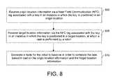
- a method for determining a path or route in which a robot may be guided to perform one or more tasksmay include receiving origin location information via a NFC tag associated with a key in an instance in which the key is positioned in an origin location.
- the methodmay further include receiving target location information via the NFC tag associated with the key in an instance in which the key is positioned in a target location, at which a task is performed by a robot.
- the methodmay further include generating a route for the robot to traverse in order to complete the task based in part on the origin location information and the target location information.
- an apparatus for determining a path or route in which a robot may be guided to perform one or more tasksmay include at least one memory and at least one processor configured to cause the apparatus to receive origin location information via a NFC tag associated with a key in an instance in which the key is positioned in an origin location.
- the processormay further cause the apparatus to receive target location information via the NFC tag associated with the key in an instance in which the key is positioned in a target location, at which a task is performed by a robot.
- the processormay further cause the apparatus to generate a route for the robot to traverse in order to complete the task based in part on the origin location information and the target location information.
- a computer program productfor determining a path or route in which a robot may be guided to perform one or more tasks.
- the computer program productincludes at least one computer-readable storage medium having computer-executable program code instructions stored therein.
- the computer-executable program code instructionsmay include program code instructions configured to cause receipt of origin location information via a NFC tag associated with a key in an instance in which the key is positioned in an origin location.
- the program code instructionsmay also cause receipt of target location information via the NFC tag associated with the key in an instance in which the key is positioned in a target location, at which a task is performed by a robot.
- the program code instructionsmay also generate a route for the robot to traverse in order to complete the task based in part on the origin location information and the target location information.
- Embodiments of the inventionmay provide a method, apparatus and computer program product for providing an efficient and reliable manner in which to teach a robot one or positions or locations for accessing targets along a route.
- device userssuch as operators may enjoy improvements with respect to teaching a robot the manner in which to acquire robot target locations or areas for the robot to avoid.
- FIG. 1is a schematic block diagram of a system according to an exemplary embodiment of the invention
- FIG. 2is a schematic block diagram of a communication device according to an exemplary embodiment of the invention.
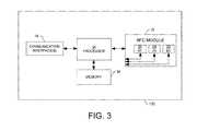
- FIG. 3is a schematic block diagram of a NFC reader according to an exemplary embodiment of the invention.
- FIG. 4is a schematic block diagram of a NFC tag according to an exemplary embodiment of the invention.
- FIG. 5is a schematic block diagram of a computing device according to an exemplary embodiment of the invention.
- FIG. 6is a diagram of a system according to an exemplary embodiment of the invention.
- FIG. 7is a flowchart of a method for determining a route in which a robot may be guided to perform one or more tasks and avoid one or more obstacles or obstructions according to an exemplary embodiment of the invention.
- FIG. 8is a flowchart of a method for determining a path or route in which a robot may be guided to perform one or more tasks according to an exemplary embodiment of the invention.
- FIG. 1is a block diagram of a system according to an exemplary embodiment.
- the systemmay include a robot 175 which may access one or more entities such as, for example, communication device 145 (e.g., servers, personal computers, laptops, workstations, personal digital assistants, smart devices, etc.), or any other suitable entity.
- communication device 145e.g., servers, personal computers, laptops, workstations, personal digital assistants, smart devices, etc.
- robotmay include all or part of an automated or semi-automated machine or apparatus that may be used to perform tasks throughout an automated environment.
- the robot 175may access the communication device 145 over a network 140 , such as a wired local area network (LAN), or a wireless local area network (WLAN), a metropolitan network (MAN) and/or a wide area network (WAN) (e.g., the Internet).
- a network 140such as a wired local area network (LAN), or a wireless local area network (WLAN), a metropolitan network (MAN) and/or a wide area network (WAN) (e.g., the Internet).
- the communication device 145may be capable of receiving data from and transmitting data to the robot 175 .
- the communication device 145may communicate with the robot 175 in accordance with a short range communication 100 or Near Field Communication (NFC) such as, for example, Radio Frequency (RF), Bluetooth (BT), Infrared (IR) or the like.
- RFRadio Frequency
- BTBluetooth
- IRInfrared
- the communication device 145may also communicate with a Near Field Communication (NFC) reader 150 (e.g., an RFID reader).
- NFCNear Field Communication
- the communication device 145may receive data from and transmit data to the NFC reader 150 via network 140 .
- the NFC reader 150may communicate with the communication device 145 when the NFC reader 150 is within a given proximity, range or distance of the communication device 145 via a short range communication 105 or Near Field Communication (NFC) such as, for example, Radio Frequency (RF), Bluetooth (BT), Infrared (IR) or the like.
- RFRadio Frequency
- BTBluetooth
- IRInfrared
- the NFC reader 150may send one or more interrogation signals to the NFC tags 28 (e.g., RFID tags) when the NFC reader 150 is within a proximity, range or distance of the NFC tags 28 .
- the interrogation signalsmay excite or trigger the NFC tags 28 to send data (e.g., RF data to the NFC reader 150 .
- the data received by the NFC reader 150 from the NFC tags 28may, but need not, be utilized to determine a location(s) corresponding to each of the respective NFC tags.
- the NFC reader 150may send this data to the communication device 145 and the communication device 145 may send the data to the robot 175 along with information identifying a path or route for the robot 175 to utilize in accessing one or more targets corresponding to the locations and/or identifying obstructions or areas to avoid corresponding to the locations, as described more fully below.
- system of FIG. 1shows one robot 175 , one communication device 145 , one NFC reader 150 and three NFC tags 28
- system of FIG. 1may include any suitable number of robots 175 , communication devices 145 , NFC readers 150 and NFC tags 28 without departing from the spirit and scope of the invention.
- functionality described herein of the communication device 145 and robot 175may be performed by a single entity.
- FIG. 2illustrates a block diagram of a communication device according to an exemplary embodiment of the invention.
- the communication device 145may, but need not, be an entity such as for example, a specifically-configured server, computer, workstation, smart device or the like.
- the communication device 145may be a network entity.
- the communication device 145includes various means for performing one or more functions in accordance with exemplary embodiments of the invention, including those more particularly shown and described herein. It should be understood, however, that the communication device may include alternative means for performing one or more like functions, without departing from the spirit and scope of the invention. More particularly, for example, as shown in FIG. 2 , the communication device may include a processor 70 connected to a memory 86 .
- the memory 86may comprise volatile and/or non-volatile memory, and typically stores content (e.g., media content), data, information or the like.
- the memory 86may store content transmitted from, and/or received by, the communication device.
- the memory 86may store one or more applications, software, or the like as well as any other suitable information.
- the memory 86may also store data associated with locations corresponding to NFC tags 28 .
- the locationsmay be utilized by the communication device 145 to instruct the robot 175 to perform a task(s) at one or more of the locations, perform one or more tasks along a route corresponding to the locations and/or avoid one or more areas corresponding to the locations.
- the memory 86typically stores client applications, instructions or the like for execution by the processor 70 to perform steps associated with operation of the communication device in accordance with embodiments of the invention.
- the memory 86may store one or more client application(s) such as for example software (e.g., computer code).
- the processor 70may be embodied in a variety of ways.
- the processor 70may be embodied as a controller, coprocessor, microprocessor of other processing devices including integrated circuits such as for example an application specific integrated circuit (ASIC), a field programmable gate array (FPGA).
- ASICapplication specific integrated circuit
- FPGAfield programmable gate array
- the processormay execute instructions stored in the memory 86 or otherwise accessible to the processor 70 .
- the communication device 145may include one or more logic elements for performing various functions of one or more client application(s).
- the communication device 145may execute the client application(s).
- the logic elements performing the functions of one or more client applicationsmay be embodied in an integrated circuit assembly including one or more integrated circuits (e.g., an ASIC, FPGA or the like) integral or otherwise in communication with a respective network entity (e.g., computing system, client, server, etc.) or more particularly, for example, a processor 70 of the respective network entity.
- the processor 70may also be connected to at least one interface or other means for displaying, transmitting and/or receiving data, content or the like.
- the interface(s)can include at least one communication interface 88 or other means for transmitting and/or receiving data, content or the like.
- the communication interface 88may include, for example, an antenna (or multiple antennas) and supporting hardware and/or software for enabling communications with a wireless communication network.
- the communication interface(s)may include a first communication interface for connecting to a first network, and a second communication interface for connecting to a second network.
- the communication deviceis capable of communicating with other electronic devices (e.g., robot 175 and NFC reader 150 ) over one or more networks (e.g., network 140 ) such as a Local Area Network (LAN), wireless LAN (WLAN), Wide Area Network (WAN), Wireless Wide Area Network (WWAN), the Internet, or the like.
- networkse.g., network 140
- the communication interfacecan support a wired connection with the respective network.
- the communication device 145may also include one or more means for sharing and/or obtaining data.
- the communication device 145may comprise a short range radio frequency (RF) transceiver and/or interrogator 20 so data may be shared with and/or obtained from electronic devices in accordance with RF techniques.
- the communication device 145may comprise other short range transceivers, such as, for example an infrared (IR) transceiver 22 , a BluetoothTM (BT) transceiver 24 operating using BluetoothTM brand wireless technology developed by the BluetoothTM (BT) Special Interest Group, and/or the like.
- the Bluetooth transceiver 24may be configured to operate according to WibreeTM radio standards.
- the communication device 145 and, in particular, the short range transceivermay be capable of transmitting data to and/or receiving data from electronic devices (e.g., NFC reader 150 , robot 175 ) within a proximity of the communication device 145 , such as within 10 meters, for example or any other suitable distance or range.
- electronic devicese.g., NFC reader 150 , robot 175
- the interface(s)may also include at least one user interface that may include one or more earphones and/or speakers, a display 80 , and/or a user input interface 77 .
- the user input interfacemay comprise any of a number of devices allowing the entity to receive data from a user, such as a microphone, a keypad, keyboard, a touch display, a joystick, image capture device, pointing device (e.g., mouse), stylus or other input device.
- the processor 70may be in communication with and may otherwise control a robot controller 78 .
- the robot controller 78may be any means such as a device or circuitry operating in accordance with software or otherwise embodied in hardware or a combination of hardware and software thereby configuring the device or circuitry (e.g. a processor or controller) to perform the corresponding functions of the robot controller 78 as described below.
- a device or circuitrye.g., processor 70 in one example
- executing the softwareforms the structure associated with such means.
- the robot controller 78may be configured to provide, among other things, means for instructing a robot to perform a task(s) at one or more locations along a route or to avoid one or more areas, locations or objects (also referred to herein interchangeably as “obstacles” or “obstructions”), as described more fully below.
- the communication device 145may be a standalone device. As described above, in an alternative exemplary embodiment, the communication device 145 may be embodied within or as part of the robot 175 .
- the NFC reader 150may include one or more means for sharing and/or obtaining data.
- the NFC reader 150may comprise a NFC module 32 that includes a short range radio frequency (RF) transceiver and/or interrogator 26 so data may be shared with and/or obtained from electronic devices in accordance with RF techniques.
- the NFC reader 150may comprise other short range transceivers, such as, for example an infrared (IR) transceiver 29 , a BluetoothTM (BT) transceiver 30 operating using BluetoothTM brand wireless technology developed by the BluetoothTM Special Interest Group, and/or the like.
- the Bluetooth transceiver 30may be configured to operate according to WibreeTM radio standards.
- the NFC reader 150 and, in particular, the NFC module 32may be capable of transmitting data to and/or receiving data from electronic devices (e.g., NFC tags, transponders, etc.) within a proximity, range or distance of the NFC reader 150 , such as within 10 meters, for example.
- the NFC module 32may be capable of transmitting data to and/or receiving data from electronic devices (e.g., NFC tags 28 , communication device 145 ) within other suitable proximities such as, for example, 20 centimeters, etc.
- the NFC reader 150may be configured to transmit and/or receive data from electronic devices according to various wireless networking techniques, including Wireless Fidelity (Wi-Fi), WLAN techniques such as IEEE 802.11 techniques (e.g., across network 140 ), and/or the like. Additionally, it should be pointed out that in an example embodiment, the NFC module 32 may be capable of reading and receiving a short-range communication or Near Field Communication upon interrogation by the NFC reader of a device (e.g., NFC tags 28 ).
- a devicee.g., NFC tags 28
- the NFC reader 150may read NFC data from a device (e.g., NFC tags, transponders, etc.) when the NFC reader 150 is within a proximity of the device(s).
- the NFC datamay be provided by the NFC reader 150 to the communication device 145 which may utilize the NFC data, in part, to instruct a robot 175 regarding the manner in which to access a location corresponding to a NFC tag(s) 28 to perform a task(s) along a route for performing one or more tasks or to avoid one or more areas or objects corresponding to locations associated with the NFC tags 28 , as described more fully below.
- the NFC reader 150may also include a processor 34 and an associated memory 36 .
- the memory 36may comprise volatile and/or non-volatile memory, and may store content, data and/or the like.
- the memorymay store content, data, information, and/or the like transmitted from, and/or received by, the NFC reader.
- the memory 36may store data received by the NFC reader 150 from one or more NFC tags 28 .
- the data received from the corresponding NFC tagsmay be utilized to determine location data identifying locations of the NFC tags 28 .
- the memory 96may store client applications, instructions, and/or the like for the processor 34 to perform the various operations of the NFC reader in accordance with embodiments of the invention, as described herein.
- the processor 34may also be connected to at least one interface or other means for transmitting and/or receiving data, content, and/or the like.
- the interface(s)may comprise at least one communication interface 38 or other means for transmitting and/or receiving data, content, and/or the like.
- the communication interface 38may be configured to communicate information across network 140 .
- the NFC reader 150may be embodied within the communication device 145 .
- the NFC tag 28(e.g., a RFID tag/chip, a BT chip and/or the like) may be embodied in a NFC key 35 (also referred to herein as RFID key 35 ).
- the NFC key 35may, but need not, be any suitable physical object with which a robot (e.g., all or part of an automated or semi-automated machine or apparatus) may interact in performance of a task. This may include, for example, a vial, a container, a cup, a bottle, a car part, and/or any possible object or component used in conjunction with performance of a task by the robot.
- one or more NFC tags 28may be associated with the NFC key 35 (e.g., incorporated within, attached thereto, etc.). As described in more detail below, in one embodiment, the number of NFC tags 28 associated with the NFC key 35 may depend upon the number of degrees of dexterity or freedom in which the robot is capable of moving.
- the NFC tag 28(also referred to herein as transponder 28 or NFC transponder 28 ) may include a transceiver such as a short range transceiver 83 having an antenna 81 .
- the NFC tag 28may also include a processor 84 and a memory 82 .
- the short range transceiver 83may be configured to operate in accordance with one or more frequencies or one or more frequency bands.
- the short range transceiver 83may communicate with other electronic devices such as, for example, the NFC reader 150 as well as other electronic devices. In this regard, the short range transceiver 83 may communicate with other electronic devices according to RF, BT, IR or any other suitable short range or Near Field Communication techniques. The short range transceiver 83 may communicate with the NFC reader 150 when the NFC reader 150 is within a given proximity, range or distance of the NFC tag 28 . In this regard, the short range transceiver 83 may send one or more interrogation signals to a respective NFC module 32 of the NFC reader 150 when the NFC reader 150 is within the proximity of the NFC tag 28 . The interrogation signals may excite or trigger the NFC module 32 to read data (e.g., RF/NFC data signals) from the NFC tag 28 .
- datae.g., RF/NFC data signals
- the memory 82may store one or more instructions (e.g., programs) associated with one or more applications, unique identifiers (IDs) as well as any other suitable data. It should be pointed out that when the NFC module 32 reads the NFC tag 28 , the NFC tag 28 may send information associated with NFC data (e.g., a unique ID(s)) stored in memory 82 to the NFC reader 150 and the sent information may be utilized in part to determine location data indicating a location corresponding to the NFC tag 28 .
- the location datamay include one or more coordinates such as, for example, an x-coordinate, a y-coordinate, a z-coordinate or any other suitable coordinates.
- the processor 84may be a controller or other processing element configured to execute instructions, which may be stored in memory 82 or perform other logical operations or functions of the NFC tag 28 as described herein.
- the processor 84may be embodied as an ASIC or an FPGA.
- the computing device 170may include a processor 44 connected to a memory device 46 .
- the memory device 46(also referred to herein as memory 46 ) may comprise volatile and/or non-volatile memory, and may store content, information, data or the like.
- the memory device 46typically stores content transmitted from, and/or received by, the computing device 170 .
- the memory 46may store data received from the robot controller 78 of the communication device 145 .
- the memory device 46may store client applications, software, software code (e.g., computer code), algorithms, instructions or the like for the processor 44 to perform steps associated with operation of the computing device 170 .
- the processor 44may be connected to at least one communication interface 48 or other means for displaying, transmitting and/or receiving data, content, information or the like.
- the communication interface 48may be capable of connecting to one or more networks (e.g., network 140 ).
- the processor 44may receive data from the robot controller 78 instructing the robot 175 to perform a task(s) at a location, perform one or more tasks along a route corresponding to one or more locations, or avoid one or more areas, locations or objects.
- the computing device 170may also include at least one user input interface 42 that may include one or more speakers, a display, and/or any other suitable devices.
- the user input interface 42may include any of a number of devices allowing the computing device 170 to receive data from a user, such as a keyboard, a keypad, mouse, a microphone, a touch screen display, or any other input device.
- the computing device 170may comprise a short range radio frequency (RF) transceiver and/or interrogator 90 so data may be shared with and/or obtained from electronic devices in accordance with RF techniques.
- the computing device 170may also comprise other short range transceivers, such as, for example an infrared (IR) transceiver 92 , a BluetoothTM (BT) transceiver 94 operating using BluetoothTM brand wireless technology developed by the BluetoothTM Special Interest Group, and/or the like.
- IRinfrared
- BTBluetoothTM
- the Bluetooth transceiver 94may operate according to WibreeTM radio standards.
- the computing device 170 and, in particular, the short range transceivermay be capable of transmitting data to and/or receiving data from electronic devices (e.g., communication device 145 ) within a proximity of the computing device 170 , such as within 10 meters, for example or any other suitable range or distance (e.g., 30 feet).
- electronic devicese.g., communication device 145
- a proximity of the computing device 170such as within 10 meters, for example or any other suitable range or distance (e.g., 30 feet).
- FIGS. 6 & 7shows a system and method, respectively, for enabling a robot (e.g., all or part of an automated or semi-automated machine or apparatus) to access one or more targets along a route and/or to avoid areas identified as obstacles according to exemplary embodiments of the invention.
- the exemplary embodimentsprovide an efficient and reliable manner in which to teach a robot positions or locations for accessing targets along a route.
- the exemplary embodimentsprovide an operator with a fast, efficient and reliable mechanism in which to acquire robot target locations or areas to avoid without actually guiding the robot to each location or area in advance of generating a route. In this manner, the impact of colliding with expensive or important support architecture and equipment in an automated environment is minimized.
- an exemplary embodiment of a systemfor determining a path or route in which a robot may be guided to perform one or more tasks and/or for avoiding one or more obstacles or obstructions.
- the following example embodimentinvolves a robot 175 operating in an automated environment to automatically fill vials, containers or the like at specific locations (e.g., targets) with medications. These locations may correspond to locations along a path or route.
- the robotmay perform any suitable automated functions or tasks (e.g., welding, painting, component assembly, etc.) without departing from the spirit and scope of the invention.
- a routemay be generated specifying a path in which a robot may be routed to access locations in which to perform functions or tasks. Additionally, it may be desirable for the robot 175 to avoid areas or objects along the path such as, for example, to minimize the impact of a collision(s) or for any other suitable reason.
- one or more NFC tags 28may be utilized in part to determine positions of targets and/or obstructions. These NFC tags 28 may be included in an NFC key 35 .
- the NFC tags 28may be embodied or mounted within the NFC key 35 and the NFC tags 28 may be utilized to record all targets and/or obstructions.
- the NFC key 35may include a number of NFC tags 28 corresponding to one or more degrees of freedom or dexterity associated with the robot.
- three NFC tagsmay be included in an NFC key 35 in an instance in which a robot 175 is capable of moving in three different directions (e.g., along the x, y and z axes).
- FIG. 6shows three NFC tags 28 included in the NFC key 35 , it should be pointed out that any suitable number of NFC tags may be included in the NFC key 35 .
- a single NFC tag 28may be used.
- a robot that is capable of rotating and moving up or downmay use two NFC tags 28 (e.g., one for angle and one for elevation).
- a robot 175 capable of moving in, for example, 10 or 12 different orientationse.g., having 10 or 12 different degrees of freedom
- the NFC key 35may be any suitable physical object that the robot 175 may be capable of handling.
- the NFC key 35may be a physical object (e.g., a cup, container, bottle, bag, etc.) that the robot 175 may utilize while performing one or more automated tasks or functions.
- a user 40such as, for example, an operator or the like, may place the NFC key 35 directly into an end effector 39 (also referred to herein as receptacle 39 ) of the robot 175 .
- the NFC key 35e.g., in the shape of a vial
- the armis in a home or origin position.
- the NFC reader 150may read data from the NFC tags and may determine an origin location of the robot 175 based on the position of the NFC tags 28 in response to placing or inserting the NFC key 35 into the end effector 39 .
- the NFC reader 150may read data from the NFC tags and may determine an origin location of the robot 175 based on the position of the NFC tags in response to powering up the robot 175 .
- the NFC reader 150may determine the location of the NFC tags 78 based in part on the signal strengths received from the respective NFC tags 28 . For example, when the received signal strength is strong, the NFC reader 150 may determine that the location of the NFC tags is closer to the NFC reader 150 . On the other hand, when the received signal strengths are weak, the NFC reader 150 may determine that the NFC tags are farther away from the NFC reader 150 .
- the processor 44 of the computing device 170 in the robot 175may know the current location of the robot 175 and may send data associated with the current location to the NFC reader 150 . For instance, the processor 44 may implement a global positioning system (GPS) feature to determine the location of the robot 175 and may send this location information to the NFC reader 150 .
- GPSglobal positioning system
- the NFC reader 150may send raw data that the NFC reader 150 may receive from the NFC tags 28 and/or the computing device 170 to the communication device 145 and the robot controller 78 may determine the locations of the NFC tags 28 and the robot 175 based in part on the information.
- the information identifying the origin location of the robot 175 and the origin locations of the NFC tags 28 that are received by the NFC reader 150may be stored in memory 36 of the NFC reader 150 by the processor 34 .
- the usere.g., the operator
- the usermay select a setting of a device (not shown) to capture one or more locations.
- the user 40may insert the NFC key 35 in a target 41 corresponding to a first location that the robot 175 is to access.
- the user 40may press a button (not shown) (also referred to herein as a switch) or the like of the device to trigger the NFC module 32 of the NFC reader 150 to read data (e.g., a unique identifier(s)) associated with the NFC tags 28 to determine the first location corresponding to the target 41 .
- the first locationmay be determined by the processor 34 based on the signal strength of the data read by the NFC module 32 from the NFC tags 28 in the NFC key 35 in the manner described above.
- the processor 34may determine the location based on the power levels between each antenna 81 of the NFC tags 28 as measured by the NFC module 32 .
- the power level for each NFC tag 28may rise the closer a respective NFC tag 28 is to the NFC reader 150 .
- the power levelmay fall as the respective NFC tag 28 is moved away from the NFC reader 150 .
- the processor 34 or the robot controller 78may be capable of interpreting the power level data measured by the NFC module 32 and determine a discrete location for each NFC tag 28 . It should be pointed out that any other suitable mechanism for determining the location of NFC tags may be utilized by the exemplary embodiments without departing from the spirit and scope of the invention.
- the data associated with the first locationmay be read by the NFC module 32 from the NFC tags 28 when the NFC reader 150 is within a proximity of the NFC key 35 that is inserted in target 41 .
- the processor 34may store the location associated with the target 41 in the memory 36 .
- the user 40may remove the NFC key 35 from the target 41 and insert the NFC key 35 in the target 43 .
- the user 40may select the button of the device which may trigger the NFC module 32 to read data (e.g., a unique identifier(s)) of the NFC tags 28 within the NFC key 35 so that the processor 34 may utilize the data to determine a second location that the robot 175 is to access.
- the processor 34may store the data associated with the second location in the memory 36 .
- the user 40may remove the NFC key 35 from the target 43 and may insert the NFC key 35 in the target 45 .
- the user 40may select the button of the device to trigger the NFC module 32 to read data of the NFC tags 28 .
- the processor 34may utilize the data to determine a third location that the robot 175 is to access.
- the processor 34 of the NFC reader 150may facilitate storage of this data associated with the third location in the memory 36 .
- the example embodiment of FIG. 6shows three targets 41 , 43 , 45 that may be utilized for determining locations for the robot 175 to access, it should be pointed out that any suitable number of targets may be included in the system of FIG. 6 for facilitating the teaching of the locations along a path to the robot 175 .
- the locationsmay include any suitable number of locations and are not limited to three locations.
- the number of targetsmay correspond to the total number of possible locations at which the robot may perform a task.
- the user 40may select a setting of a device (not shown) to assign areas, locations, or objects for the robot 175 to avoid.
- the user 40may utilize one or more additional targets (e.g., targets 51 , 53 ) to facilitate determination of a location(s), area(s) or object(s) that the robot 175 should avoid.
- the user 40may place the target 51 at a physical location which may be on an object(s) and may insert the NFC key 35 in the target 51 .
- the targetmay be a location in space, such as, for example, a weld location or a paint location or any other suitable location.
- the NFC key 35may be placed at a location, such as for example, on the edge of a table (or a floor) and when the position of the table (or the floor) is recorded, the corresponding location may denote the target.
- some targetsmay correspond to a location of a hole in an instance in which the NFC key 35 is inserted into a cylinder while other targets may correspond to a center of roof of a car where a robot is to paint.
- the NFC key 35may be placed on the roof and the position of the roof may be recorded as denoting the target.
- the user 40may select the button of the device which may trigger the NFC module 32 of the NFC reader 150 to read data of the NFC tags 28 .
- the processor 34may determine the location associated with the NFC tags 28 in a manner analogous to that described above.
- the processor 34 of the NFC reader 150may define or assign the location as an obstacle or obstruction denoting that the robot 175 should be instructed to avoid the corresponding location.
- the processor 34may facilitate storage of the data regarding the assignment in the memory 36 .
- the user 40may place the target 53 at another physical location and may insert the NFC key 35 in the target 53 .
- the usermay select a button (not shown) of a device (not shown) to trigger the NFC module 32 to read the data of the NFC tags 28 .
- the processor 34may determine the location corresponding to the NFC tags 28 of the NFC key 35 that is inserted in target 53 .
- the processor 34may assign this location as another obstacle or obstruction denoting that the robot 175 is to be instructed to avoid the respective location.
- the data regarding the assignmentmay be stored by the processor 34 in the memory 36 .
- the processor 34may send the location information to the communication device 145 . Additionally, the processor 34 of the NFC reader 150 may provide the data relating to the origin location of the robot 175 and the original locations of NFC tags 28 that were inserted in the end effector 39 of the robot 175 to the communication device 145 .
- the robot controller 78 of the communication device 145may, in one embodiment, calculate one or more best routes (also referred to herein as best paths) for the robot to move about in an automated environment and perform one or more tasks (e.g., filling vials of medicine, etc.) at specified locations.
- the route(s)may include, for example, a route from the origin location to each of the target locations. Alternatively, or in addition, the route(s) may include a route between multiple targets.
- the best routemay be determined by the robot controller 78 based on implementing a GPS feature with respect to the location information provided by the NFC reader 150 .
- the best routemay be determined by the robot controller 78 based on data received from one or more motor encoders of the robot 175 .
- the robot 175may determine its location based on feedback from one or more of the motor encoders that provided the robot with data relating to the location of one or more parts (e.g., an automated arm) of the robot 175 and the range of motion of the parts.
- This location datamay be provided by the robot 175 to the robot controller 78 such that the robot controller 78 may utilize the location information to determine the best route.
- the data associated with the best route(s)may be sent by the robot controller 78 to the processor 44 of the computing device 170 maintained in the robot 175 .
- the processor 44may evaluate data associated with the best route(s) and may instruct the robot 175 to move about and operate in an automated environment according to the best route(s).
- the robot 175may be guided by the processor 44 to one or more locations for performing a task(s) or function(s) as defined by the best route(s) and the robot 175 may avoid locations, or areas assigned as an obstacle(s) or obstruction(s).
- the robot controller 78may instruct the robot 175 to move about and operate in the automated environment according to the best route(s) without communicating with the processor 44 .
- the robot controller 78may send only the location information (e.g., origin, target and obstacle location information), and not the best route(s), to the processor 44 .
- the robot controller 78 or the processor 44 of the computing device 170 maintained in the robot 175may calculate the best route(s) at some later point in time.
- the processor 44may calculate the best route to perform one or more tasks in real-time in response to receiving instructions to perform the task(s).
- a robot used to dispense medicationsmay calculate the best route for the robotic arm to take in order to gather the medications in response to receiving instructions that include the specific medications to be dispensed.
- the NFC reader 150may send the origin location of the robot 175 , the original locations of the NFC tags 28 and other location information relating to targets or obstructions to the communication device 145 together as a batch.
- the NFC reader 150may provide this data to the communication device 145 as the data is received from one or more NFC tags 28 or the robot 175 .
- the processor 34 of the NFC reader 150may send corresponding location information associated with the NFC tag 28 to the communication device 145 without waiting on the NFC module 32 to receive data read from NFC tags 28 inserted at other targets.
- the user 40may have decided not to select areas, locations or obstructions for the robot 175 to avoid.
- the robot 175may move about an automated environment according to the best route without respect to any information instructing the robot 175 to avoid any obstacles or obstructions.
- the usermay decide to utilize the setting of a device (not shown) to define one or more areas, locations or objects to avoid but may decide not to select locations for the robot 175 to perform tasks along a route.
- the processor 44or alternatively the robot controller 78 , may instruct the robot 175 to avoid the areas, locations, or objects when the robot 175 is moved about an automated environment.
- an apparatuse.g., communication device 145
- may receive location information from a devicee.g., the NFC reader 150
- at least one apparatuse.g., communication device 145 and/or NFC reader 150
- may determine that the received location informationis based in part on receipt of data via one or more Near Field Communications.
- an apparatuse.g., communication device 145
- an apparatuse.g., communication device 145
- at least one apparatuse.g., communication device 145 or computing device 170
- an apparatuse.g., communication device 145
- NFCNear Field Communication
- an apparatuse.g., communication device 145
- a robote.g., robot 175
- an apparatuse.g., communication device 145
- FIGS. 7 and 8are flowcharts of a system, method and computer program product according to exemplary embodiments of the invention. It will be understood that each block or step of the flowcharts, and combinations of blocks in the flowcharts, can be implemented by various means, such as hardware, firmware, and/or a computer program product including one or more computer program instructions. For example, one or more of the procedures described above may be embodied by computer program instructions. In this regard, in an example embodiment, the computer program instructions which embody the procedures described above are stored by a memory device (e.g., memory 86 , memory 46 , memory 36 ) and executed by a processor (e.g., processor 70 , processor 44 , processor 34 , robot controller 78 ).
- a memory devicee.g., memory 86 , memory 46 , memory 36
- a processore.g., processor 70 , processor 44 , processor 34 , robot controller 78 .
- any such computer program instructionsmay be loaded onto a computer or other programmable apparatus (e.g., hardware) to produce a machine, such that the instructions which execute on the computer or other programmable apparatus cause the functions specified in the flowcharts blocks or steps to be implemented.
- the computer program instructionsare stored in a computer-readable memory that can direct a computer or other programmable apparatus to function in a particular manner, such that the instructions stored in the computer-readable memory produce an article of manufacture including instructions which implement the function specified in the flowcharts blocks or steps.
- the computer program instructionsmay also be loaded onto a computer or other programmable apparatus to cause a series of operational steps to be performed on the computer or other programmable apparatus to produce a computer-implemented process such that the instructions which execute on the computer or other programmable apparatus provide steps for implementing the functions specified in the flowcharts blocks or steps.
- blocks or steps of the flowchartssupport combinations of means for performing the specified functions and combinations of steps for performing the specified functions. It will also be understood that one or more blocks or steps of the flowcharts, and combinations of blocks or steps in the flowcharts, can be implemented by special purpose hardware-based computer systems which perform the specified functions or steps, or combinations of special purpose hardware and computer instructions.
- an apparatus for performing the methods of FIGS. 7 and 8 abovemay comprise a processor (e.g., the processor 70 , the processor 44 , the processor 34 ) configured to perform some or each of the operations described above.
- the processormay, for example, be configured to perform the operations by performing hardware implemented logical functions, executing stored instructions, or executing algorithms for performing each of the operations.
- the apparatusmay comprise means for performing each of the operations described above.
- examples of means for performing operationsmay comprise, for example, the processor 34 , the processor 44 , the processor 70 (e.g., as means for performing any of the operations described above), the robot controller 78 and/or a device or circuit for executing instructions or executing an algorithm for processing information as described above.
Landscapes
- Engineering & Computer Science (AREA)
- Physics & Mathematics (AREA)
- General Physics & Mathematics (AREA)
- Automation & Control Theory (AREA)
- Robotics (AREA)
- Mechanical Engineering (AREA)
- Electromagnetism (AREA)
- Aviation & Aerospace Engineering (AREA)
- Radar, Positioning & Navigation (AREA)
- Remote Sensing (AREA)
- Manipulator (AREA)
Abstract
Description
Claims (20)
Priority Applications (2)
| Application Number | Priority Date | Filing Date | Title |
|---|---|---|---|
| US12/973,551US8694162B2 (en) | 2010-12-20 | 2010-12-20 | Methods, apparatuses and computer program products for utilizing near field communication to guide robots |
| CA2759740ACA2759740C (en) | 2010-12-20 | 2011-11-28 | Methods, apparatuses and computer program products for utilizing near field communication to guide robots |
Applications Claiming Priority (1)
| Application Number | Priority Date | Filing Date | Title |
|---|---|---|---|
| US12/973,551US8694162B2 (en) | 2010-12-20 | 2010-12-20 | Methods, apparatuses and computer program products for utilizing near field communication to guide robots |
Publications (2)
| Publication Number | Publication Date |
|---|---|
| US20120158235A1 US20120158235A1 (en) | 2012-06-21 |
| US8694162B2true US8694162B2 (en) | 2014-04-08 |
Family
ID=46235450
Family Applications (1)
| Application Number | Title | Priority Date | Filing Date |
|---|---|---|---|
| US12/973,551Active2032-07-23US8694162B2 (en) | 2010-12-20 | 2010-12-20 | Methods, apparatuses and computer program products for utilizing near field communication to guide robots |
Country Status (2)
| Country | Link |
|---|---|
| US (1) | US8694162B2 (en) |
| CA (1) | CA2759740C (en) |
Cited By (6)
| Publication number | Priority date | Publication date | Assignee | Title |
|---|---|---|---|---|
| US9393699B1 (en) | 2014-12-05 | 2016-07-19 | Google Inc. | Methods and systems for wireless control of a robotic device |
| US9833907B1 (en) | 2015-06-22 | 2017-12-05 | X Development Llc | Proximity-based binding |
| CN108136584A (en)* | 2015-11-19 | 2018-06-08 | 株式会社安川电机 | Robotic systems and remote control systems |
| USRE49068E1 (en) | 2009-02-10 | 2022-05-10 | Mckesson High Volume Solutions, Inc. | Computer system for pill dispensing devices |
| US20220283060A1 (en)* | 2012-08-31 | 2022-09-08 | Gopro, Inc. | Apparatus and methods for controlling attention of a robot |
| US11735304B2 (en) | 2017-09-26 | 2023-08-22 | Mckesson Corporation | Robotic dispensary system and methods |
Families Citing this family (25)
| Publication number | Priority date | Publication date | Assignee | Title |
|---|---|---|---|---|
| US20120306443A1 (en)* | 2011-06-03 | 2012-12-06 | GM Global Technology Operations LLC | Automated charging for vehicle energy storage systems |
| US20140102859A1 (en) | 2012-10-12 | 2014-04-17 | Mckesson Automation Inc. | Apparatuses, systems, and methods for dispensing medications from a central pharmacy to a patient in a healthcare facility |
| US9150119B2 (en) | 2013-03-15 | 2015-10-06 | Aesynt Incorporated | Apparatuses, systems, and methods for anticipating and delivering medications from a central pharmacy to a patient using a track based transport system |
| WO2014135049A1 (en)* | 2013-03-04 | 2014-09-12 | Yau Yimwai | Communication terminal product supporting interactive association system |
| US9446471B2 (en)* | 2013-03-15 | 2016-09-20 | Lincoln Global, Inc. | Systems and methods for communicating with welding equipment |
| US20150284231A1 (en)* | 2014-04-05 | 2015-10-08 | RF Identity, Inc. | Systems and methods for validation of personal protection equipment on aerial work platforms |
| US9826364B2 (en)* | 2015-04-03 | 2017-11-21 | Qualcomm Incorporated | Systems and methods for location-based tuning |
| US10591592B2 (en) | 2015-06-15 | 2020-03-17 | Humatics Corporation | High-precision time of flight measurement systems |
| EP3307055A4 (en)* | 2015-06-15 | 2019-03-13 | Humatics Corporation | HIGH PRECISION FLIGHT TIME MEASUREMENT SYSTEM FOR INDUSTRIAL AUTOMATION |
| US10422870B2 (en) | 2015-06-15 | 2019-09-24 | Humatics Corporation | High precision time of flight measurement system for industrial automation |
| CN107949766A (en)* | 2015-06-15 | 2018-04-20 | 修麦提克斯公司 | High-precision time-of-flight measurement system |
| US10665923B2 (en) | 2015-12-17 | 2020-05-26 | Humatics Corporation | Chip-scale radio-frequency localization devices and associated systems and methods |
| DE102016206529A1 (en)* | 2016-04-19 | 2017-10-19 | Robert Bosch Gmbh | Assembly workstation with positioning device |
| KR102402134B1 (en)* | 2016-08-26 | 2022-05-30 | 크라운 이큅먼트 코포레이션 | Material Handling Vehicle Path Validation and Dynamic Path Correction |
| CN108873802A (en)* | 2018-08-02 | 2018-11-23 | 佛山职业技术学院 | A kind of circuit control system cleaning detection robot for photovoltaic module |
| EP3628452A1 (en)* | 2018-09-25 | 2020-04-01 | Nxp B.V. | System and method for controlling a robotic device |
| CN109918768A (en)* | 2019-03-04 | 2019-06-21 | 南方电网科学研究院有限责任公司 | Path searching planning method and device of electric energy metering device based on password chip |
| CN112449300A (en)* | 2019-08-15 | 2021-03-05 | 纳恩博(北京)科技有限公司 | Method and device for updating position information, storage medium and electronic device |
| CN110977984B (en)* | 2019-12-23 | 2023-05-05 | 上海钛米机器人科技有限公司 | Control strip, mechanical arm control method, device, system and storage medium |
| CN111954188B (en)* | 2020-07-30 | 2024-01-19 | 深圳优地科技有限公司 | Robot control method, device, terminal and medium |
| US12080415B2 (en) | 2020-10-09 | 2024-09-03 | Humatics Corporation | Radio-frequency systems and methods for co-localization of medical devices and patients |
| WO2023286838A1 (en)* | 2021-07-15 | 2023-01-19 | 住友重機械工業株式会社 | Autonomous traveling truck and method for assembling autonomous traveling truck |
| CN114397889B (en)* | 2021-12-22 | 2024-03-26 | 深圳银星智能集团股份有限公司 | Full-coverage path planning method based on unit decomposition and related equipment |
| CN115533901A (en)* | 2022-09-29 | 2022-12-30 | 中国联合网络通信集团有限公司 | Robot control method, system and storage medium |
| CN116000923B (en)* | 2022-12-26 | 2025-03-28 | 江苏科技大学 | A FPGA deployment system and method for a robot's six-degree-of-freedom visual target detection DETR model |
Citations (91)
| Publication number | Priority date | Publication date | Assignee | Title |
|---|---|---|---|---|
| US4717042A (en) | 1986-05-28 | 1988-01-05 | Pyxis Corporation | Medicine dispenser for home health care |
| US4785969A (en) | 1986-11-10 | 1988-11-22 | Pyxis Corporation | Medication dispensing system |
| US4847764A (en) | 1987-05-21 | 1989-07-11 | Meditrol, Inc. | System for dispensing drugs in health care institutions |
| US5014875A (en) | 1989-03-01 | 1991-05-14 | Pyxis Corporation | Medication dispenser station |
| US5190185A (en) | 1990-05-18 | 1993-03-02 | Baxter International Inc. | Medication transport and dispensing magazine |
| US5314243A (en) | 1992-12-04 | 1994-05-24 | Automated Healthcare, Inc. | Portable nursing center |
| US5346297A (en) | 1993-01-04 | 1994-09-13 | Colson Jr Angus R | Auxiliary storage and dispensing unit |
| US5377864A (en) | 1989-05-25 | 1995-01-03 | Baxter International Inc. | Drug dispensing apparatus |
| US5405048A (en) | 1993-06-22 | 1995-04-11 | Kvm Technologies, Inc. | Vacuum operated medicine dispenser |
| US5431299A (en) | 1994-01-26 | 1995-07-11 | Andrew E. Brewer | Medication dispensing and storing system with dispensing modules |
| US5460294A (en) | 1994-05-12 | 1995-10-24 | Pyxis Corporation | Single dose pharmaceutical dispenser subassembly |
| US5468110A (en) | 1990-01-24 | 1995-11-21 | Automated Healthcare, Inc. | Automated system for selecting packages from a storage area |
| US5661978A (en) | 1994-12-09 | 1997-09-02 | Pyxis Corporation | Medical dispensing drawer and thermoelectric device for cooling the contents therein |
| USD384578S (en) | 1996-08-01 | 1997-10-07 | Automated Healthcare, Inc. | Unit dose medicine package |
| US5713485A (en) | 1995-10-18 | 1998-02-03 | Adds, Inc. | Drug dispensing system |
| US5716114A (en) | 1996-06-07 | 1998-02-10 | Pyxis Corporation | Jerk-resistant drawer operating system |
| US5745366A (en) | 1994-07-14 | 1998-04-28 | Omnicell Technologies, Inc. | Pharmaceutical dispensing device and methods |
| US5761877A (en) | 1996-02-23 | 1998-06-09 | Quandt; W. Gerald | System for individual dosage medication distribution |
| US5797515A (en) | 1995-10-18 | 1998-08-25 | Adds, Inc. | Method for controlling a drug dispensing system |
| US5805456A (en) | 1994-07-14 | 1998-09-08 | Omnicell Technologies, Inc. | Device and method for providing access to items to be dispensed |
| US5842976A (en) | 1996-05-16 | 1998-12-01 | Pyxis Corporation | Dispensing, storage, control and inventory system with medication and treatment chart record |
| US5880443A (en) | 1990-01-24 | 1999-03-09 | Automated Healthcare | Automated system for selecting packages from a cylindrical storage area |
| US5878885A (en) | 1997-10-14 | 1999-03-09 | Automated Healthcare, Inc. | Blister package with sloped raised formations |
| US5883806A (en) | 1994-09-28 | 1999-03-16 | Kvm Technologies, Inc. | Secure medication storage and retrieval system |
| US5893697A (en) | 1997-03-26 | 1999-04-13 | Automated Healthcare, Inc. | Automated system for selecting packages from a storage area |
| US5905653A (en) | 1994-07-14 | 1999-05-18 | Omnicell Technologies, Inc. | Methods and devices for dispensing pharmaceutical and medical supply items |
| US5912818A (en) | 1993-01-25 | 1999-06-15 | Diebold, Incorporated | System for tracking and dispensing medical items |
| US5927540A (en) | 1997-08-20 | 1999-07-27 | Omnicell Technologies, Inc. | Controlled dispensing system and method |
| US5940306A (en) | 1993-05-20 | 1999-08-17 | Pyxis Corporation | Drawer operating system |
| US5971593A (en) | 1994-12-16 | 1999-10-26 | Diebold, Incorporated | Dispensing system for medical items |
| US6003006A (en) | 1996-12-09 | 1999-12-14 | Pyxis Corporation | System of drug distribution to health care providers |
| US6011999A (en) | 1997-12-05 | 2000-01-04 | Omnicell Technologies, Inc. | Apparatus for controlled dispensing of pharmaceutical and medical supplies |
| US6021392A (en) | 1996-12-09 | 2000-02-01 | Pyxis Corporation | System and method for drug management |
| US6039467A (en) | 1996-12-05 | 2000-03-21 | Omnicell Technologies, Inc. | Lighting system and methods for a dispensing device |
| US6109774A (en) | 1995-08-01 | 2000-08-29 | Pyxis Corporation | Drawer operating system |
| US6112502A (en) | 1998-02-10 | 2000-09-05 | Diebold, Incorporated | Restocking method for medical item dispensing system |
| US6116461A (en) | 1998-05-29 | 2000-09-12 | Pyxis Corporation | Method and apparatus for the dispensing of drugs |
| US6151536A (en) | 1998-09-28 | 2000-11-21 | Omnicell.Com | Dispensing system and methods |
| US6170230B1 (en) | 1998-12-04 | 2001-01-09 | Automed Technologies, Inc. | Medication collecting system |
| US6176392B1 (en) | 1997-12-05 | 2001-01-23 | Mckesson Automated Prescription Systems, Inc. | Pill dispensing system |
| US6189727B1 (en) | 1999-03-24 | 2001-02-20 | S&S X-Ray Products, Inc. | Pharmaceutical dispensing arrangement |
| US6223934B1 (en) | 2000-01-18 | 2001-05-01 | S&S X-Ray Products, Inc. | Scrub dispensing cabinet |
| US6256967B1 (en) | 1998-08-27 | 2001-07-10 | Automed Technologies, Inc. | Integrated automated drug dispenser method and apparatus |
| US6289656B1 (en) | 2000-07-12 | 2001-09-18 | Mckesson Automated Healthcare, Inc. | Packaging machine |
| US6339732B1 (en) | 1998-10-16 | 2002-01-15 | Pyxis Corporation | Apparatus and method for storing, tracking and documenting usage of anesthesiology items |
| US6361263B1 (en) | 1998-12-10 | 2002-03-26 | Pyxis Corporation | Apparatus and method of inventorying packages on a storage device |
| US6370841B1 (en) | 1999-12-03 | 2002-04-16 | Automed Technologies, Inc. | Automated method for dispensing bulk medications with a machine-readable code |
| US6497342B2 (en) | 2000-11-30 | 2002-12-24 | Mckesson Automated Healthcare, Inc. | Medicine feeder |
| US6499270B2 (en) | 1997-08-04 | 2002-12-31 | Pyxis Corporation | Method and apparatus for transferring objects |
| US6532399B2 (en) | 2001-06-05 | 2003-03-11 | Baxter International Inc. | Dispensing method using indirect coupling |
| US6564121B1 (en) | 1999-09-22 | 2003-05-13 | Telepharmacy Solutions, Inc. | Systems and methods for drug dispensing |
| US6609047B1 (en) | 1993-07-21 | 2003-08-19 | Omnicell Technologies, Inc. | Methods and apparatus for dispensing items |
| US6611733B1 (en) | 1996-12-20 | 2003-08-26 | Carlos De La Huerga | Interactive medication dispensing machine |
| US6640159B2 (en) | 1996-12-05 | 2003-10-28 | Omnicell Technologies, Inc. | Replacement liner and methods for a dispensing device |
| US6650964B2 (en) | 2002-04-16 | 2003-11-18 | Mckesson Automation Inc. | Medication dispensing apparatus override check and communication system |
| US6755931B2 (en) | 2002-07-18 | 2004-06-29 | Mckesson Automation Systems Inc. | Apparatus and method for applying labels to a container |
| US6760643B2 (en) | 1994-10-11 | 2004-07-06 | Omnicell, Inc. | Methods and apparatus for dispensing items |
| US6785589B2 (en) | 2001-11-30 | 2004-08-31 | Mckesson Automation, Inc. | Dispensing cabinet with unit dose dispensing drawer |
| US6790198B1 (en) | 1999-12-01 | 2004-09-14 | B-Braun Medical, Inc. | Patient medication IV delivery pump with wireless communication to a hospital information management system |
| US6847861B2 (en) | 2001-11-30 | 2005-01-25 | Mckesson Automation, Inc. | Carousel product for use in integrated restocking and dispensing system |
| US20050055127A1 (en)* | 2001-12-26 | 2005-03-10 | Lockheed Martin Corporation | Apparatus and methods for performing operations on an object |
| US6874684B1 (en) | 1999-10-29 | 2005-04-05 | Mckesson Automation Systems Inc. | Automated will call system |
| US6895304B2 (en) | 2001-12-07 | 2005-05-17 | Mckesson Automation, Inc. | Method of operating a dispensing cabinet |
| US6975922B2 (en) | 2003-05-08 | 2005-12-13 | Omnicell, Inc. | Secured dispensing cabinet and methods |
| US6996456B2 (en) | 2002-10-21 | 2006-02-07 | Fsi International, Inc. | Robot with tactile sensor device |
| US7014063B2 (en) | 2002-08-09 | 2006-03-21 | Mckesson Automation Systems, Inc. | Dispensing device having a storage chamber, dispensing chamber and a feed regulator there between |
| US7052097B2 (en) | 2002-12-06 | 2006-05-30 | Mckesson Automation, Inc. | High capacity drawer with mechanical indicator for a dispensing device |
| US7072855B1 (en) | 2000-07-24 | 2006-07-04 | Omnicell, Inc. | Systems and methods for purchasing, invoicing and distributing items |
| US7092796B2 (en) | 2003-11-14 | 2006-08-15 | Cardinal Health 303, Inc. | System and method for verifying connection of correct fluid supply to an infusion pump |
| US7100792B2 (en) | 2002-08-30 | 2006-09-05 | Omnicell, Inc. | Automatic apparatus for storing and dispensing packaged medication and other small elements |
| US7103419B2 (en) | 1995-05-15 | 2006-09-05 | Cardinal Health 303, Inc. | System and method for monitoring medication delivery to a patient |
| US7111780B2 (en) | 2002-10-18 | 2006-09-26 | Mckesson Automation Systems Inc. | Automated drug substitution, verification, and reporting system |
| US7139639B2 (en) | 2002-07-29 | 2006-11-21 | Mckesson Automation Systems Inc. | Article dispensing and counting method and device |
| US7150724B2 (en) | 2002-06-05 | 2006-12-19 | Cardinal Health 303, Inc. | Syringe plunger driver system |
| US20060293794A1 (en)* | 2005-06-28 | 2006-12-28 | Harwig Jeffrey L | RFID navigational system for robotic floor treater |
| US20070061041A1 (en)* | 2003-09-02 | 2007-03-15 | Zweig Stephen E | Mobile robot with wireless location sensing apparatus |
| US20070065259A1 (en)* | 2005-08-30 | 2007-03-22 | Talley Paul A | Automated self storage system |
| US7218231B2 (en) | 2004-07-29 | 2007-05-15 | Omnicell, Inc. | Method and apparatus for preparing an item with an RFID tag |
| US7228198B2 (en) | 2002-08-09 | 2007-06-05 | Mckesson Automation Systems, Inc. | Prescription filling apparatus implementing a pick and place method |
| US20080039974A1 (en)* | 2006-03-17 | 2008-02-14 | Irobot Corporation | Robot Confinement |
| US7348884B2 (en) | 2004-07-29 | 2008-03-25 | Omnicell, Inc. | RFID cabinet |
| US7417729B2 (en) | 2003-11-07 | 2008-08-26 | Cardinal Health 303, Inc. | Fluid verification system and method for infusions |
| US7419133B2 (en) | 2004-07-16 | 2008-09-02 | Cardinal Health 303, Inc. | Automatic clamp apparatus for IV infusion sets used in pump devices |
| US20080224867A1 (en)* | 2007-03-13 | 2008-09-18 | Oracle International Corporation | Real-Time and Offline Location Tracking Using Passive RFID Technologies |
| US20090030551A1 (en)* | 2007-07-25 | 2009-01-29 | Thomas Kent Hein | Method and system for controlling a mobile robot |
| US20090319077A1 (en)* | 2006-07-24 | 2009-12-24 | Rolls-Royce Plc. | Control of a machining operation |
| US20100114372A1 (en)* | 2008-10-30 | 2010-05-06 | Intellibot Robotics Llc | Method of cleaning a surface using an automatic cleaning device |
| US20100241273A1 (en)* | 2007-07-19 | 2010-09-23 | Ko Chien-Ho | Device for retrieving data from a radio frequency identification tag |
| US20120029697A1 (en)* | 2010-07-30 | 2012-02-02 | Toyota Motor Engineering & Manufacturing North America, Inc. | Robotic transportation devices and systems |
| US20120072023A1 (en)* | 2010-09-22 | 2012-03-22 | Toyota Motor Engineering & Manufacturing North America, Inc. | Human-Robot Interface Apparatuses and Methods of Controlling Robots |
| US20120283867A1 (en)* | 2009-11-24 | 2012-11-08 | Siemens Healthcare Diagnostics Inc. | Automated, refrigerated specimen inventory management system |
- 2010
- 2010-12-20USUS12/973,551patent/US8694162B2/enactiveActive
- 2011
- 2011-11-28CACA2759740Apatent/CA2759740C/enactiveActive
Patent Citations (126)
| Publication number | Priority date | Publication date | Assignee | Title |
|---|---|---|---|---|
| US4717042A (en) | 1986-05-28 | 1988-01-05 | Pyxis Corporation | Medicine dispenser for home health care |
| US4785969A (en) | 1986-11-10 | 1988-11-22 | Pyxis Corporation | Medication dispensing system |
| US4847764A (en) | 1987-05-21 | 1989-07-11 | Meditrol, Inc. | System for dispensing drugs in health care institutions |
| US4847764C1 (en) | 1987-05-21 | 2001-09-11 | Meditrol Inc | System for dispensing drugs in health care instituions |
| US5014875A (en) | 1989-03-01 | 1991-05-14 | Pyxis Corporation | Medication dispenser station |
| US5377864A (en) | 1989-05-25 | 1995-01-03 | Baxter International Inc. | Drug dispensing apparatus |
| US5880443A (en) | 1990-01-24 | 1999-03-09 | Automated Healthcare | Automated system for selecting packages from a cylindrical storage area |
| US5593267A (en) | 1990-01-24 | 1997-01-14 | Automated Healthcare, Inc. | Automated system for selecting and delivering packages from a storage area |
| US5468110A (en) | 1990-01-24 | 1995-11-21 | Automated Healthcare, Inc. | Automated system for selecting packages from a storage area |
| US5190185A (en) | 1990-05-18 | 1993-03-02 | Baxter International Inc. | Medication transport and dispensing magazine |
| US5564803A (en) | 1992-12-04 | 1996-10-15 | Automated Healthcare, Inc. | Portable nursing center |
| US5314243A (en) | 1992-12-04 | 1994-05-24 | Automated Healthcare, Inc. | Portable nursing center |
| US5346297A (en) | 1993-01-04 | 1994-09-13 | Colson Jr Angus R | Auxiliary storage and dispensing unit |
| US5520450A (en) | 1993-01-04 | 1996-05-28 | Pyxis Corporation | Supply station with internal computer |
| US5912818A (en) | 1993-01-25 | 1999-06-15 | Diebold, Incorporated | System for tracking and dispensing medical items |
| US5940306A (en) | 1993-05-20 | 1999-08-17 | Pyxis Corporation | Drawer operating system |
| US5405048A (en) | 1993-06-22 | 1995-04-11 | Kvm Technologies, Inc. | Vacuum operated medicine dispenser |
| US5480062A (en) | 1993-06-22 | 1996-01-02 | Kvm Technologies, Inc. | Vacuum operated medicine dispenser |
| US6609047B1 (en) | 1993-07-21 | 2003-08-19 | Omnicell Technologies, Inc. | Methods and apparatus for dispensing items |
| US5431299A (en) | 1994-01-26 | 1995-07-11 | Andrew E. Brewer | Medication dispensing and storing system with dispensing modules |
| US5460294A (en) | 1994-05-12 | 1995-10-24 | Pyxis Corporation | Single dose pharmaceutical dispenser subassembly |
| US5805456A (en) | 1994-07-14 | 1998-09-08 | Omnicell Technologies, Inc. | Device and method for providing access to items to be dispensed |
| US5745366A (en) | 1994-07-14 | 1998-04-28 | Omnicell Technologies, Inc. | Pharmaceutical dispensing device and methods |
| US5905653A (en) | 1994-07-14 | 1999-05-18 | Omnicell Technologies, Inc. | Methods and devices for dispensing pharmaceutical and medical supply items |
| US5883806A (en) | 1994-09-28 | 1999-03-16 | Kvm Technologies, Inc. | Secure medication storage and retrieval system |
| US6760643B2 (en) | 1994-10-11 | 2004-07-06 | Omnicell, Inc. | Methods and apparatus for dispensing items |
| US5661978A (en) | 1994-12-09 | 1997-09-02 | Pyxis Corporation | Medical dispensing drawer and thermoelectric device for cooling the contents therein |
| US5971593A (en) | 1994-12-16 | 1999-10-26 | Diebold, Incorporated | Dispensing system for medical items |
| US7171277B2 (en) | 1995-05-15 | 2007-01-30 | Cardinal Health 303, Inc. | System and method for controlling the delivery of medication to a patient |
| US7103419B2 (en) | 1995-05-15 | 2006-09-05 | Cardinal Health 303, Inc. | System and method for monitoring medication delivery to a patient |
| US6109774A (en) | 1995-08-01 | 2000-08-29 | Pyxis Corporation | Drawer operating system |
| US6065819A (en) | 1995-08-01 | 2000-05-23 | Pyxis Corporation | Jerk-resistant drawer operation system |
| US6581798B2 (en) | 1995-10-18 | 2003-06-24 | Telepharmacy Solutions, Incorporated | Method for controlling a drug dispensing system |
| US5713485A (en) | 1995-10-18 | 1998-02-03 | Adds, Inc. | Drug dispensing system |
| US6471089B2 (en) | 1995-10-18 | 2002-10-29 | Telepharmacy Solutions, Inc. | Method for controlling a drug dispensing system |
| US5797515A (en) | 1995-10-18 | 1998-08-25 | Adds, Inc. | Method for controlling a drug dispensing system |
| US6283322B1 (en) | 1995-10-18 | 2001-09-04 | Telepharmacy Solutions, Inc. | Method for controlling a drug dispensing system |
| US6776304B2 (en) | 1995-10-18 | 2004-08-17 | Telepharmacy Solutions, Inc. | Method for controlling a drug dispensing system |
| US6814254B2 (en) | 1995-10-18 | 2004-11-09 | Telepharmacy Solutions, Incorporated | Method for controlling a drug dispensing system |
| US6068156A (en) | 1995-10-18 | 2000-05-30 | Adds, Inc. | Method for controlling a drug dispensing system |
| US6814255B2 (en) | 1995-10-18 | 2004-11-09 | Telepharmacy Solutions, Inc. | Method for controlling a drug dispensing system |
| US5761877A (en) | 1996-02-23 | 1998-06-09 | Quandt; W. Gerald | System for individual dosage medication distribution |
| US5842976A (en) | 1996-05-16 | 1998-12-01 | Pyxis Corporation | Dispensing, storage, control and inventory system with medication and treatment chart record |
| US5716114A (en) | 1996-06-07 | 1998-02-10 | Pyxis Corporation | Jerk-resistant drawer operating system |
| USD384578S (en) | 1996-08-01 | 1997-10-07 | Automated Healthcare, Inc. | Unit dose medicine package |
| US6039467A (en) | 1996-12-05 | 2000-03-21 | Omnicell Technologies, Inc. | Lighting system and methods for a dispensing device |
| US6640159B2 (en) | 1996-12-05 | 2003-10-28 | Omnicell Technologies, Inc. | Replacement liner and methods for a dispensing device |
| US6021392A (en) | 1996-12-09 | 2000-02-01 | Pyxis Corporation | System and method for drug management |
| US6003006A (en) | 1996-12-09 | 1999-12-14 | Pyxis Corporation | System of drug distribution to health care providers |
| US6611733B1 (en) | 1996-12-20 | 2003-08-26 | Carlos De La Huerga | Interactive medication dispensing machine |
| US5893697A (en) | 1997-03-26 | 1999-04-13 | Automated Healthcare, Inc. | Automated system for selecting packages from a storage area |
| US6499270B2 (en) | 1997-08-04 | 2002-12-31 | Pyxis Corporation | Method and apparatus for transferring objects |
| US5927540A (en) | 1997-08-20 | 1999-07-27 | Omnicell Technologies, Inc. | Controlled dispensing system and method |
| US5878885A (en) | 1997-10-14 | 1999-03-09 | Automated Healthcare, Inc. | Blister package with sloped raised formations |
| US6176392B1 (en) | 1997-12-05 | 2001-01-23 | Mckesson Automated Prescription Systems, Inc. | Pill dispensing system |
| US6011999A (en) | 1997-12-05 | 2000-01-04 | Omnicell Technologies, Inc. | Apparatus for controlled dispensing of pharmaceutical and medical supplies |
| US6681149B2 (en) | 1997-12-05 | 2004-01-20 | Mckesson Automation Systems Inc. | Pill dispensing system |
| US7016766B2 (en) | 1997-12-05 | 2006-03-21 | Mckesson Automated Prescription Systems, Inc. | Pill dispensing system |
| US6112502A (en) | 1998-02-10 | 2000-09-05 | Diebold, Incorporated | Restocking method for medical item dispensing system |
| US7040504B2 (en) | 1998-05-29 | 2006-05-09 | Cardinal Health 301, Inc. | System and apparatus for the dispensing of drugs |
| US6338007B1 (en) | 1998-05-29 | 2002-01-08 | Pyxis Corporation | System and apparatus for the storage and dispensing of items |
| US6116461A (en) | 1998-05-29 | 2000-09-12 | Pyxis Corporation | Method and apparatus for the dispensing of drugs |
| US6742671B2 (en) | 1998-08-27 | 2004-06-01 | Automed Technologies, Inc. | Integrated automated drug dispenser method and apparatus |
| US6256967B1 (en) | 1998-08-27 | 2001-07-10 | Automed Technologies, Inc. | Integrated automated drug dispenser method and apparatus |
| US6449927B2 (en) | 1998-08-27 | 2002-09-17 | Automed Technologies, Inc. | Integrated automated drug dispenser method and apparatus |
| US6151536A (en) | 1998-09-28 | 2000-11-21 | Omnicell.Com | Dispensing system and methods |
| US6339732B1 (en) | 1998-10-16 | 2002-01-15 | Pyxis Corporation | Apparatus and method for storing, tracking and documenting usage of anesthesiology items |
| US6625952B1 (en) | 1998-12-04 | 2003-09-30 | Automed Technologies, Inc. | Medication collecting system |
| US6170230B1 (en) | 1998-12-04 | 2001-01-09 | Automed Technologies, Inc. | Medication collecting system |
| US6361263B1 (en) | 1998-12-10 | 2002-03-26 | Pyxis Corporation | Apparatus and method of inventorying packages on a storage device |
| US6189727B1 (en) | 1999-03-24 | 2001-02-20 | S&S X-Ray Products, Inc. | Pharmaceutical dispensing arrangement |
| US6564121B1 (en) | 1999-09-22 | 2003-05-13 | Telepharmacy Solutions, Inc. | Systems and methods for drug dispensing |
| US7093755B2 (en) | 1999-10-29 | 2006-08-22 | Mckesson Automation Systems Inc. | Automated will call system |
| US6874684B1 (en) | 1999-10-29 | 2005-04-05 | Mckesson Automation Systems Inc. | Automated will call system |
| US6790198B1 (en) | 1999-12-01 | 2004-09-14 | B-Braun Medical, Inc. | Patient medication IV delivery pump with wireless communication to a hospital information management system |
| US6370841B1 (en) | 1999-12-03 | 2002-04-16 | Automed Technologies, Inc. | Automated method for dispensing bulk medications with a machine-readable code |
| US6223934B1 (en) | 2000-01-18 | 2001-05-01 | S&S X-Ray Products, Inc. | Scrub dispensing cabinet |
| US6289656B1 (en) | 2000-07-12 | 2001-09-18 | Mckesson Automated Healthcare, Inc. | Packaging machine |
| US7072855B1 (en) | 2000-07-24 | 2006-07-04 | Omnicell, Inc. | Systems and methods for purchasing, invoicing and distributing items |
| US6497342B2 (en) | 2000-11-30 | 2002-12-24 | Mckesson Automated Healthcare, Inc. | Medicine feeder |
| US6532399B2 (en) | 2001-06-05 | 2003-03-11 | Baxter International Inc. | Dispensing method using indirect coupling |
| US6847861B2 (en) | 2001-11-30 | 2005-01-25 | Mckesson Automation, Inc. | Carousel product for use in integrated restocking and dispensing system |
| US6996455B2 (en) | 2001-11-30 | 2006-02-07 | Mckesson Automation Inc. | Dispensing cabinet with unit dose dispensing drawer |
| US7010389B2 (en) | 2001-11-30 | 2006-03-07 | Mckesson Automation, Inc. | Restocking system using a carousel |
| US7072737B2 (en) | 2001-11-30 | 2006-07-04 | Mckesson Automation, Inc. | Filling a restocking package using a carousel |
| US6785589B2 (en) | 2001-11-30 | 2004-08-31 | Mckesson Automation, Inc. | Dispensing cabinet with unit dose dispensing drawer |
| US6895304B2 (en) | 2001-12-07 | 2005-05-17 | Mckesson Automation, Inc. | Method of operating a dispensing cabinet |
| US6985797B2 (en) | 2001-12-07 | 2006-01-10 | Mckesson Automation, Inc. | Method of operating a dispensing cabinet |
| US7085621B2 (en) | 2001-12-07 | 2006-08-01 | Mckesson Automation, Inc. | Method of operating a dispensing cabinet |
| US20050055127A1 (en)* | 2001-12-26 | 2005-03-10 | Lockheed Martin Corporation | Apparatus and methods for performing operations on an object |
| US6650964B2 (en) | 2002-04-16 | 2003-11-18 | Mckesson Automation Inc. | Medication dispensing apparatus override check and communication system |
| US6671579B2 (en) | 2002-04-16 | 2003-12-30 | Mckesson Automation, Inc. | Override having built in audit trail for medication dispensing and administering systems |
| US7150724B2 (en) | 2002-06-05 | 2006-12-19 | Cardinal Health 303, Inc. | Syringe plunger driver system |
| US6755931B2 (en) | 2002-07-18 | 2004-06-29 | Mckesson Automation Systems Inc. | Apparatus and method for applying labels to a container |
| US6892780B2 (en) | 2002-07-18 | 2005-05-17 | Mckesson Automation Systems, Inc. | Apparatus for applying labels to a container |
| US7139639B2 (en) | 2002-07-29 | 2006-11-21 | Mckesson Automation Systems Inc. | Article dispensing and counting method and device |
| US7077286B2 (en) | 2002-08-09 | 2006-07-18 | Mckesson Automation Systems Inc. | Drug dispensing cabinet having a drawer interlink, counterbalance and locking system |
| US7014063B2 (en) | 2002-08-09 | 2006-03-21 | Mckesson Automation Systems, Inc. | Dispensing device having a storage chamber, dispensing chamber and a feed regulator there between |
| US7228198B2 (en) | 2002-08-09 | 2007-06-05 | Mckesson Automation Systems, Inc. | Prescription filling apparatus implementing a pick and place method |
| US7100792B2 (en) | 2002-08-30 | 2006-09-05 | Omnicell, Inc. | Automatic apparatus for storing and dispensing packaged medication and other small elements |
| US7588167B2 (en) | 2002-08-30 | 2009-09-15 | Omnicell, Inc. | Automatic apparatus for storing and dispensing packaged medication and other small elements |
| US7249688B2 (en) | 2002-08-30 | 2007-07-31 | Omnicell, Inc. | Automatic apparatus for storing and dispensing packaged medication and other small elements |
| US7111780B2 (en) | 2002-10-18 | 2006-09-26 | Mckesson Automation Systems Inc. | Automated drug substitution, verification, and reporting system |
| US6996456B2 (en) | 2002-10-21 | 2006-02-07 | Fsi International, Inc. | Robot with tactile sensor device |
| US7426425B2 (en) | 2002-12-06 | 2008-09-16 | Mckesson Automation Inc. | High capacity drawer with mechanical indicator for a dispensing device |
| US7052097B2 (en) | 2002-12-06 | 2006-05-30 | Mckesson Automation, Inc. | High capacity drawer with mechanical indicator for a dispensing device |
| US7571024B2 (en) | 2003-05-08 | 2009-08-04 | Omnicell, Inc. | Secured dispensing cabinet and methods |
| US6975922B2 (en) | 2003-05-08 | 2005-12-13 | Omnicell, Inc. | Secured dispensing cabinet and methods |
| US20070061041A1 (en)* | 2003-09-02 | 2007-03-15 | Zweig Stephen E | Mobile robot with wireless location sensing apparatus |
| US7417729B2 (en) | 2003-11-07 | 2008-08-26 | Cardinal Health 303, Inc. | Fluid verification system and method for infusions |
| US7092796B2 (en) | 2003-11-14 | 2006-08-15 | Cardinal Health 303, Inc. | System and method for verifying connection of correct fluid supply to an infusion pump |
| US7419133B2 (en) | 2004-07-16 | 2008-09-02 | Cardinal Health 303, Inc. | Automatic clamp apparatus for IV infusion sets used in pump devices |
| US7218231B2 (en) | 2004-07-29 | 2007-05-15 | Omnicell, Inc. | Method and apparatus for preparing an item with an RFID tag |
| US7348884B2 (en) | 2004-07-29 | 2008-03-25 | Omnicell, Inc. | RFID cabinet |
| US7554449B2 (en) | 2004-07-29 | 2009-06-30 | Omnicell, Inc. | Method and apparatus for preparing an item with an RFID tag |
| US20060293794A1 (en)* | 2005-06-28 | 2006-12-28 | Harwig Jeffrey L | RFID navigational system for robotic floor treater |
| US20070065259A1 (en)* | 2005-08-30 | 2007-03-22 | Talley Paul A | Automated self storage system |
| US20080039974A1 (en)* | 2006-03-17 | 2008-02-14 | Irobot Corporation | Robot Confinement |
| US20090319077A1 (en)* | 2006-07-24 | 2009-12-24 | Rolls-Royce Plc. | Control of a machining operation |
| US20080224867A1 (en)* | 2007-03-13 | 2008-09-18 | Oracle International Corporation | Real-Time and Offline Location Tracking Using Passive RFID Technologies |
| US20100241273A1 (en)* | 2007-07-19 | 2010-09-23 | Ko Chien-Ho | Device for retrieving data from a radio frequency identification tag |
| US20090030551A1 (en)* | 2007-07-25 | 2009-01-29 | Thomas Kent Hein | Method and system for controlling a mobile robot |
| US20100114372A1 (en)* | 2008-10-30 | 2010-05-06 | Intellibot Robotics Llc | Method of cleaning a surface using an automatic cleaning device |
| US20120283867A1 (en)* | 2009-11-24 | 2012-11-08 | Siemens Healthcare Diagnostics Inc. | Automated, refrigerated specimen inventory management system |
| US20120029697A1 (en)* | 2010-07-30 | 2012-02-02 | Toyota Motor Engineering & Manufacturing North America, Inc. | Robotic transportation devices and systems |
| US20120072023A1 (en)* | 2010-09-22 | 2012-03-22 | Toyota Motor Engineering & Manufacturing North America, Inc. | Human-Robot Interface Apparatuses and Methods of Controlling Robots |
Cited By (7)
| Publication number | Priority date | Publication date | Assignee | Title |
|---|---|---|---|---|
| USRE49068E1 (en) | 2009-02-10 | 2022-05-10 | Mckesson High Volume Solutions, Inc. | Computer system for pill dispensing devices |
| US20220283060A1 (en)* | 2012-08-31 | 2022-09-08 | Gopro, Inc. | Apparatus and methods for controlling attention of a robot |
| US11867599B2 (en)* | 2012-08-31 | 2024-01-09 | Gopro, Inc. | Apparatus and methods for controlling attention of a robot |
| US9393699B1 (en) | 2014-12-05 | 2016-07-19 | Google Inc. | Methods and systems for wireless control of a robotic device |
| US9833907B1 (en) | 2015-06-22 | 2017-12-05 | X Development Llc | Proximity-based binding |
| CN108136584A (en)* | 2015-11-19 | 2018-06-08 | 株式会社安川电机 | Robotic systems and remote control systems |
| US11735304B2 (en) | 2017-09-26 | 2023-08-22 | Mckesson Corporation | Robotic dispensary system and methods |
Also Published As
| Publication number | Publication date |
|---|---|
| CA2759740C (en) | 2015-03-17 |
| US20120158235A1 (en) | 2012-06-21 |
| CA2759740A1 (en) | 2012-06-20 |
Similar Documents
| Publication | Publication Date | Title |
|---|---|---|
| US8694162B2 (en) | Methods, apparatuses and computer program products for utilizing near field communication to guide robots | |
| US10962648B2 (en) | Detecting sensor orientation characteristics using marker-based localization | |
| US10675759B2 (en) | Interference region setting apparatus for mobile robot | |
| CN107671863B (en) | Robot control method and device based on two-dimensional code and robot | |
| KR101526639B1 (en) | Automatic guided vehicle and travel control method | |
| US11185984B2 (en) | Method and apparatus for controlling robot | |
| US11981518B2 (en) | Robotic tools and methods for operating the same | |
| CN112975976A (en) | Article checking method and system, robot control device and robot | |
| US8909371B2 (en) | Specifying a permitted movement range with a pointer | |
| WO2023069462A2 (en) | Systems and methods for controlled cleaning of vehicles | |
| US10988312B2 (en) | Wireless tag reading system | |
| KR102123111B1 (en) | RFID Reader Apparatus and Server Appratus | |
| US20240182282A1 (en) | Hybrid autonomous system and human integration system and method | |
| US20250230023A1 (en) | Validating the pose of a robotic vehicle that allows it to interact with an object on fixed infrastructure | |
| KR20230034390A (en) | Calibration of industrial vehicle distance and ranging devices | |
| US12292535B2 (en) | Method and system for calibrating a light-curtain | |
| EP3361338A1 (en) | Storage of object data in device for determination of object position | |
| JP2024010564A (en) | Route setting method, program and route setting system | |
| WO2024137167A2 (en) | Configuring a system that handles uncertainty with human and logic collaboration in a material flow automation solution | |
| WO2023192267A1 (en) | A system for amrs that leverages priors when localizing and manipulating industrial infrastructure | |
| EP4630343A1 (en) | Systems and methods for material flow automation | |
| US20190022862A1 (en) | Position definition in coordinate system of a robot by device placement | |
| CN114683299A (en) | Robot tool and method of operating the same |
Legal Events
| Date | Code | Title | Description |
|---|---|---|---|
| AS | Assignment | Owner name:MCKESSON AUTOMATION, INC., PENNSYLVANIA Free format text:ASSIGNMENT OF ASSIGNORS INTEREST;ASSIGNOR:JAYNES, ROBERT;REEL/FRAME:025531/0009 Effective date:20101220 | |
| AS | Assignment | Owner name:AESYNT INCORPORATED, PENNSYLVANIA Free format text:CHANGE OF NAME;ASSIGNOR:MCKESSON AUTOMATION INC.;REEL/FRAME:032366/0589 Effective date:20131104 | |
| STCF | Information on status: patent grant | Free format text:PATENTED CASE | |
| AS | Assignment | Owner name:TPG SPECIALTY LENDING, INC., AS ADMINISTRATIVE AGE Free format text:PATENT SECURITY AGREEMENT;ASSIGNOR:AESYNT INCORPORATED;REEL/FRAME:032912/0215 Effective date:20140508 | |
| AS | Assignment | Owner name:AESYNT INCORPORATED, PENNSYLVANIA Free format text:RELEASE BY SECURED PARTY;ASSIGNOR:TPG SPECIALTY LENDING, INC., AS ADMINISTRATIVE AGENT;REEL/FRAME:037444/0566 Effective date:20160105 | |
| MAFP | Maintenance fee payment | Free format text:PAYMENT OF MAINTENANCE FEE, 4TH YEAR, LARGE ENTITY (ORIGINAL EVENT CODE: M1551) Year of fee payment:4 | |
| MAFP | Maintenance fee payment | Free format text:PAYMENT OF MAINTENANCE FEE, 8TH YEAR, LARGE ENTITY (ORIGINAL EVENT CODE: M1552); ENTITY STATUS OF PATENT OWNER: LARGE ENTITY Year of fee payment:8 | |
| AS | Assignment | Owner name:OMNICELL, INC., CALIFORNIA Free format text:MERGER AND CHANGE OF NAME;ASSIGNORS:AESYNT HOLDINGS, INC.;OMNICELL, INC.;REEL/FRAME:059110/0716 Effective date:20191230 Owner name:AESYNT HOLDINGS, INC., PENNSYLVANIA Free format text:MERGER AND CHANGE OF NAME;ASSIGNORS:AESYNT INCORPORATED;AESYNT HOLDINGS, INC.;REEL/FRAME:059110/0676 Effective date:20191230 | |
| AS | Assignment | Owner name:WELLS FARGO BANK, NATIONAL ASSOCIATION, AS ADMINISTRATIVE AGENT, VIRGINIA Free format text:SECURITY INTEREST;ASSIGNOR:OMNICELL, INC.;REEL/FRAME:066703/0184 Effective date:20240223 |