US8693945B2 - System and method for detecting and measuring uplink traffic in signal repeating systems - Google Patents
System and method for detecting and measuring uplink traffic in signal repeating systemsDownload PDFInfo
- Publication number
- US8693945B2 US8693945B2US13/693,821US201213693821AUS8693945B2US 8693945 B2US8693945 B2US 8693945B2US 201213693821 AUS201213693821 AUS 201213693821AUS 8693945 B2US8693945 B2US 8693945B2
- Authority
- US
- United States
- Prior art keywords
- uplink path
- circuitry
- signal
- signals
- gain
- Prior art date
- Legal status (The legal status is an assumption and is not a legal conclusion. Google has not performed a legal analysis and makes no representation as to the accuracy of the status listed.)
- Active
Links
Images


Classifications
- H—ELECTRICITY
- H04—ELECTRIC COMMUNICATION TECHNIQUE
- H04B—TRANSMISSION
- H04B17/00—Monitoring; Testing
- H04B17/40—Monitoring; Testing of relay systems
- H—ELECTRICITY
- H04—ELECTRIC COMMUNICATION TECHNIQUE
- H04B—TRANSMISSION
- H04B7/00—Radio transmission systems, i.e. using radiation field
- H04B7/24—Radio transmission systems, i.e. using radiation field for communication between two or more posts
- H04B7/26—Radio transmission systems, i.e. using radiation field for communication between two or more posts at least one of which is mobile
- H04B7/2603—Arrangements for wireless physical layer control
- H04B7/2606—Arrangements for base station coverage control, e.g. by using relays in tunnels
- H—ELECTRICITY
- H04—ELECTRIC COMMUNICATION TECHNIQUE
- H04B—TRANSMISSION
- H04B7/00—Radio transmission systems, i.e. using radiation field
- H04B7/14—Relay systems
- H04B7/15—Active relay systems
- H04B7/155—Ground-based stations
- H04B7/15528—Control of operation parameters of a relay station to exploit the physical medium
- H04B7/15535—Control of relay amplifier gain
- H—ELECTRICITY
- H04—ELECTRIC COMMUNICATION TECHNIQUE
- H04W—WIRELESS COMMUNICATION NETWORKS
- H04W24/00—Supervisory, monitoring or testing arrangements
- H04W24/08—Testing, supervising or monitoring using real traffic
Definitions
- the present inventionis directed generally to signal repeating systems, such as repeaters or distributed antenna systems, for wireless communications, and more particularly to a system and method for detecting uplink traffic from mobile user equipment within those systems.
- an overall wireless communication systemmay consist of a plurality of base transceiver stations (BTS) or base stations that communicate with each other and with user equipment, such as cellular phones, to provide a defined coverage area.
- BTSbase transceiver stations
- user equipmentsuch as cellular phones
- coverage areasthere are often smaller geographical areas that have very low signal coverage, as provided by one or more of the base stations.
- areas of low signal coveragemay be within buildings or in areas that are otherwise obstructed, such as by terrain features or man-made structures. Rather than simply implementing another costly and large base station to provide coverage in such low signal areas, repeaters and distributed antenna systems are often utilized.
- signal repeating systemsWhile repeaters and distributed antenna systems (herein collectively, “signal repeating systems”) may adequately extend coverage, it may be desirable to eventually install a dedicated BTS in order to increase the amount of capacity offered in the area. To that end, it is desirable to be able to determine the relative loading and traffic of a signal repeating system so that a building owner or other system operator is aware of the traffic requirements for that wireless environment.
- RSSIreceive signal strength indication
- the RSSI-based detection method for determining traffic within a wireless environment or networkis used extensively in GSM repeaters and distributed antenna systems.
- the uplink RSSIis utilized to determine the uplink traffic from mobiles that are within the coverage range of a signal repeating system.
- the signal repeating systemidentifies the channels used by the adjacent base stations and it then distributes and amplifies the signals in order to monitor the equivalent uplink (UL) frequencies. If the RSSI level on a UL channel exceeds a certain threshold, the system can detect the UL traffic.
- the threshold levelis usually a level above the receiver input noise floor for the signal repeating system.
- the specific delta with respect to the noise floordepends upon the acceptable probability of having false positive detections, which might be triggered by regular thermal noise peaks.
- the signal repeating systemcan determine the RSSI within a certain timeslot by synchronizing itself with the base station through the detection of the downlink (DL) signal. Therefore, for such a gated RSSI measurement, the repeater or distributed antenna system can measure UL activity on a timeslot-per-timeslot basis.
- the repeater or distributed antenna system operating in such a networkessentially acts to extend the UL receiver of the base station.
- the repeater/DASexperiences the same low level receive signal from the user equipment devices. That is, the receive signal level from those devices is at the noise level, or even below the noise level, for the repeater/DAS. As such, this makes the use of RSSI-based uplink traffic detection and measurement generally unfeasible for such networks.
- a traffic measurement system for a repeater/DASthat can adequately detect and measure the uplink traffic within a spread spectrum network, such as a CDMA or WCDMA network or another network where the UL signal is at or close to the noise level of the system.
- FIG. 1is a schematic view of a repeater system for implementing an embodiment of the present invention.
- FIG. 2is a schematic diagram of a distributed antenna system for implementing an embodiment of the present invention.
- FIG. 3is a more detailed schematic illustration of a repeater system for implementing an embodiment of the present invention.
- FIG. 3Ais a schematic of another repeater system for implementing an embodiment of the present invention.
- FIG. 4is a more detailed schematic illustration of a distributed antenna system implementing an embodiment of the present invention.
- FIG. 4Ais a schematic of another distributed antenna system for implementing an embodiment of the present invention.
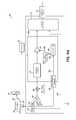
- FIG. 5is a graphical illustration of the effect of repeater gain variation on the received power of a base station with UL power control in operation.
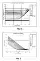
- FIG. 6is a graphical illustration of the effect of repeater gain variation on the power received at the repeater.
- the present inventionincorporates a system and method that utilizes an RSSI-based mechanism to determine the presence of uplink (UL) traffic within a CDMA network or other network to measure the strength of the detected UL traffic.
- the gain of a signal repeating systemsuch as a repeater or DAS, is periodically varied in the uplink direction.
- the uplink received power, or RSSI, for the expected uplink channel of the repeating systemis measured over time.
- a suitable measurement receiveris utilized for the purposes of measuring the RSSI.
- the measurement receiveris tuned to match the center frequency and signal bandwidth that is to be measured for the purposes of the invention.
- the measurement receivermay be configured for receiving either an analog signal or a digital signal within the signal processing uplink path, and will generally be coupled in the signal path at a point that precedes the stage providing the gain variation.
- the waveform that is utilized to provide the periodic gain variation in the uplink pathis then inverted due to the inverse relationship between the gain and RSSI values and the inverted waveform is then cross-correlated with the received UL time-variant RSSI values.
- the level of the peak, or the number of peaksare analyzed to determine the amount of traffic in the system. If no peak is detected, then the system determines that there is no UL traffic in the repeater.
- the correlation processmight only provide a single peak wherein the peak is higher or wider, depending on the amount of traffic handled by the repeater.
- the inventive systemtakes into account that the base station (BTS) may experience an increased amount of traffic, which will increase the UL input power to the BTS for the same amount of UL traffic in the repeater/DAS cell, which will inherently increase the transmit power received (RSSI) at the input to the uplink path of the repeater/DAS.
- BTSbase station
- RSSItransmit power received
- FIGS. 1 and 2illustrate exemplary signal repeating systems that may incorporate embodiments of the present invention.
- a basic wireless communication system 10incorporating a signal repeating system 14 , is shown.
- System 10includes a base station (BTS) 12 that communicates with a repeater system 14 that has at least one donor antenna 16 , at least one coverage antenna 18 , and processing electronics 20 that are coupled between the antennas 16 and 18 to process and amplify the repeated signal.
- BTSbase station
- the present inventionmay be used with MIMO systems and communication schemes, and thus, may have multiple donor antennas and multiple coverage antennas, as would be understood by a person of ordinary skill in the art. Therefore, antennas 52 , 58 are reflective of one or more antennas.
- the downlink signals(BTS to mobile device/UE) are indicated by direction DL, while the uplink signals (mobile device/UE to BTS) are indicated by direction UL.
- downlink wireless signals 22are received from the BTS 12 by the donor antenna 16 of the repeater, and are then amplified, processed, and repeated through the coverage antenna 18 as downlink signals 22 a .
- the downlink signals 22 aare received by one or more wireless communication devices, such as mobile phones or other user equipment (UE) device 24 .
- the wireless UE devices 24communicate uplink signals 26 a back to the coverage antenna and the repeated uplink signals 26 are then provided back to the BTS 12 .
- UE devices 24 athat communicate with BTS 12 directly rather than through a repeater 14 .
- Such devices 24 acontributed to the overall traffic handled by the BTS 12 .
- signal repeating systems 14can take many different forms and are not limited only to devices conventionally called “repeaters”.
- FIG. 2illustrates a schematic diagram for another exemplary signal repeating system that may implement the invention.
- a distributed antenna system (DAS) 30may be appropriately coupled to a BTS, such as BTS 12 in a wired or wireless fashion.
- the distributed antenna system 30might be incorporated into a building environment and includes a number of remote antenna units 32 that are distributed in the environment to provide coverage within a service area of the DAS 30 . In that way, the remote antenna units 32 service a number of different UE devices 24 operating in the environment of the DAS 30 .
- each remote antenna unit 32typically includes at least one antenna 36 and suitable electronics 38 . As noted above, if the invention is implemented in a MIMO system, multiple antennas 36 might be used.
- antennas 36are reflective of one or more antennas.
- Remote antenna units 32are coupled to one or more master units 40 , which combine and process the signals from the remote antenna units 32 to interface appropriately with the BTS 12 .
- a system controller 42couples to and controls the operation of each of the master units 40 for handling and processing the signals 33 associated with the remote antenna units 32 .
- the signals 33 of the remote antenna units 32are reflective of the uplink and downlink signals of the DAS 30 for communicating with UE devices 24 .
- Such a DAS 30may incorporate any number of remote antenna units and master units, and thus, would not be limited to the illustrated example shown in FIG. 2 .
- periodic gain variationis provided in the repeater or DAS uplink path.
- the gain in the UL pathmight be varied according to a periodic waveform.
- the periodic gain variation and waveformis synchronized with the framing interval of the spread spectrum network, such as a CDMA network, although such synchronization is not necessary.
- the UL receive power (UL RSSI value) in the selected UL channelis measured over time by the signal repeating system.
- the waveform that is utilized to periodically vary the gain in the uplink pathis then cross-correlated with the UL received time-variant RSSI values. Based upon such cross-correlation of those signals, the existence of one or more peaks is determined.
- the signal repeating systemwould provide an indication that there is generally no repeater traffic as the periodic gain variation would not cause any variation in the uplink RSSI values.
- the periodic gain variationcauses variations in the uplink RSSI values
- the cross-correlation performed by the signal repeating systemwould yield one or more signal peaks.
- Such peaksare an indication that if there is uplink traffic from UE devices within the coverage area of the signal repeating system.
- the level of the peak and its width as well as the energy in the peak if integrated over the time delay of the cross-correlationmay be indicative of the amount of traffic within the coverage area of the signal repeating system.
- the overall traffic in the BTScan affect the peak levels, as discussed below.
- the measured uplink RSSI valuesmight be averaged according to an averaging scheme over time that reduces fast RSSI value fluctuations without affecting or reducing the correlation peak.
- the present inventionworks not only with CDMA-type signals, but also other system signals and network signals that allow for the received power at the BTS to be close to the noise floor and even below the input noise floor of the BTS.
- OFDM modulated systemssuch as LTE systems might benefit from the present invention.
- the periodic gain variation in the signal repeating systemis performed without significantly affecting the noise figure of the signal repeating system.
- the gain of the systemis varied by changing the gain in an amplification stage of the repeater or DAS that is not very close to the input of the uplink path. That is, a latter gain stage in the uplink path is used for the periodic gain variation.
- a selected periodic waveformis used to periodically vary the gain of the UL path of the signal repeating system. Such a waveform may be adapted to the specific mobile standard that is used within the signal repeating system.
- the periodic gain variationis controlled so that the size of the gain variation and its time period is not faster than the mobile standard allows or can handle.
- CDMA mobile devicescan handle 800 power control steps of one dB per second.
- the implemented periodic UL gain variationdoes not exceed that rate of change when the invention is utilized within a CDMA system.
- other systemswill have other gain variation constraints that would be implemented in the invention.
- the gain variationis provided by reducing the gain in a periodic fashion in the signal repeating system.
- various different waveformsmight be utilized to periodically reduce the system gain in the UL path.
- an inverted Sawtooth function with gapsmay be used as a possible periodic gain variation function.
- the present inventionprovides maximization of the cross-correlation peak between the inverted gain variation function and measured UL input RSSI.
- the gain variation functionmay be aligned in phase and frequency with the mobile standard (e.g. CDMA).
- the sensitivity of the traffic detectionmay be increased by averaging multiple consecutive (i.e. several consecutive frames) cross-correlation curves.
- the periodic nature of the gain variationallows such averaging of the cross-correlation curves.
- the length of the data that is measuredis ideally an integer multiple of a frame length of the particular mobile standard, such as the CDMA standard.
- the bandwidth and center frequency settings of the RSSI measurement receiverwill depend on the used channel and expected standard.
- the used channel and standardcan be determined through the detection and decoding of the equivalent DL signal using a decoding receiver. This DL signal decoding does not necessarily have to be performed with a dedicated receiver as the standard is not expected to change. A scanning DL decoding receiver would be sufficient.
- a sub-band architecturewill allow a different gain variation in time or in amplitude within two or more different sub-bands.
- a sub-bandis a section within the RF band that represents a subset of the entire bandwidth. There can be multiple sub-bands with the RF band. Sub-bands might be adjacent to each other or have a section between them with no amplification. In the implementation of the sub-bands a surface acoustic wave filter (SAW) might be used to define the sub-band. In a digital implementation of the invention, a digital filter such as a FIR filter or IIR filter could be used instead to define the sub-band. This will allow optimizing the cross-correlation function for each standard. For each sub-band, only one mobile communication standard is allowed for optimization.
- SAWsurface acoustic wave filter
- FIGS. 3 , 3 A, 4 , and 4 Aillustrate detailed schematics of possible implementations of the invention.
- FIGS. 3 and 3Aillustrate repeater systems.
- FIGS. 4 and 4Aillustrate implementation within a DAS system, as illustrated in FIG. 1 .
- Like reference numeralsare used for like elements in the various Figures.
- FIG. 3a schematic block diagram of a repeater 50 is illustrated.
- FIG. 3shows the uplink path (UL) 62 for the repeater for illustration purposes.
- the repeater 50also incorporates a suitable downlink (DL) path 64 that would use some similar components as the downlink paths between the BTS 12 and devices 24 .
- Diplexers 55 , 95are utilized to handle the UL and DL paths through the antennas 52 , 58 .
- a repeater 50incorporates a receive antenna 52 (or coverage antenna) for processing input signals 54 from one or more mobile UE devices 24 .
- the input signals 54represent the input signals from the UE devices 24 that are to be repeated.
- signals 54represent the UE traffic to be detected in accordance with the invention.
- the repeated transmit signals 56 illustrated in FIG. 3include the transmitted signals or signal portions that are directed in the uplink to BTS 12 by a coverage antenna 58 .
- the terms “signal” or “signals”are used interchangeably herein to refer to the signal(s) handled by the signal repeating system and are not limited to just a single signal or plurality of signals.
- repeater 50includes suitable electronics 60 that are operably coupled between the antennas 52 , 58 .
- suitable electronicswill include gain control circuitry 84 that provides a desired or selected gain G in the repeater and processing 72 and correlation 100 circuitry to implement the invention.
- the repeater circuitry 20might process the signals in the analog domain in accordance with aspects of the invention.
- electronics 20 of the repeatermight provide the various aspects of the invention in the digital domain.
- FIG. 3sets forth a schematic diagram with respect to one embodiment of the invention in the form of a repeater device.
- the features of the inventionmight be incorporated in other signal repeating systems, such as a distributed antenna system, as illustrated in FIGS. 2 , 4 , and 4 A.
- componentsare shown in an uplink path 62 in the repeater 50 .
- Various similar componentswill exist in the downlink path 64 for handling downlink traffic between wireless UE devices 24 and a BTS 12 for example. Accordingly, various components within the uplink path 62 will be described herein in further detail with the assumption that some similar functionality and components would be utilized in the downlink path 64 as well, although the periodic gain variation of the invention might only be used in the uplink path.
- Digital signal processing circuitry 72is implemented for providing the filtering and further frequency conversion of the signals, as well as for periodically adjusting gain and for providing the necessary cross-correlation and signal processing to detect UL traffic in accordance with the invention.
- an ND converter circuit 74converts the analog signal to an appropriate digital signal for further digital processing.
- the DSP circuitry 72might be an FPGA, ASIC, digital signal processor or other such element.
- the DSP circuitrymight include an additional digital mixer circuit 76 fed by a suitable numerically-controlled oscillator (NCO) signal to provide digital downconversion for ease of further processing.
- NCOnumerically-controlled oscillator
- the signalmight also be filtered by an appropriate digital filter 78 . Filter 78 might also change the amplitude of the signal.
- Gain circuitry 80 or amplification circuitryprovides gain amplification to the repeated signals.
- Components 80 and 84represent suitable circuitry for periodically adjusting or varying the gain within repeater 50 for the invention.
- the signalsmight then be digitally upconverted by appropriate digital upconversion circuitry 86 fed by a transmit NCO.
- the signalsmay then be converted back to analog signals by D/A circuitry 88 .
- FIG. 3Ashows an analog repeater for implementing the present invention. Like reference numerals are utilized for those components similar between FIGS. 3 and 3A .
- gain stages 81 , 82 , and 83might be implemented in an analog fashion with analog filters, such as SAW filters 85 and 87 providing the desired filtering.
- the correlation circuitry 100might still be implemented by appropriate digital signal processing (DSP) circuitry.
- DSPdigital signal processing
- certain portions of the gain control circuitry 84might be implemented digitally.
- the analog signalsare further upconverted with mixer circuitry 90 fed by an appropriate transmit LO to an appropriate RF signal.
- the RF signalis filtered by filter circuitry 92 , and then fed to an RF power amplifier 94 before being transmitted as a repeated signal 56 through the transmit or donor antenna 58 .
- the various mixing and filter elementsare typical of a repeater. There can be more or fewer mixing elements than illustrated in the examples and still implement a functional repeater.
- the noted cross-correlation functionalityis provided by suitable processing circuitry and correlation circuitry 100 , such as within the digital signal processing (DSP) circuitry 72 , or otherwise implement digitally, as in FIG. 3A .
- DSPdigital signal processing
- the cross-correlations to determine UL trafficare performed by capturing samples 102 of the signals in the UL path at the UL input and providing RSSI values reflective of the receive power of the signals at the UL input for the cross-correlation.
- a suitable measurement receiver 101is utilized to capture signals in the uplink path and to provide RSSI values reflective of the received power of such signals.
- the bandwidth and center frequency of the RSSI measurement receiver 101are turned and configured to detect the RF signal of interest. Therefore, the bandwidth and center frequency would depend on the used channel and the expected standard for the signal.
- the used channel and standardmay be determined through the detection decoding of the equivalent downlink signal such as by using a decoding receiver.
- the downlink signal decodingwould not necessarily have to be performed with a dedicated receiver, as the signal standard would not be expected to change.
- a scanning downlink decoding receiverwould be sufficient.
- One example of such decoding receiver 105is illustrated in the downlink path 64 of the figures. As illustrated in FIG.
- the capture point for the signalis illustrated close to the coverage antenna wherein an appropriate coupler 107 captures the signal that is then directed to the measurement receiver 101 .
- the capture point for such datacan be anywhere between the coverage antenna and the amplification stage that performs the periodic gain changes. Accordingly, as illustrated in FIG. 3A , the capture point is indicated following filter 70 . Accordingly, the capture point can be directed at various different points along the uplink path, with the condition that it is before the components or stages that perform the periodic gain changes.
- the measurement receiver 101can either be implemented as analog circuitry with an A/D converter to provide the digitized measured RSSI to the correlation circuitry or as digital circuitry on a repeater system with digital signal processing where the input to the measurement receiver is captured at a point after the A/D converter 74 .
- the correlation circuitry 100 coupled to the measurement receiver 101samples the RSSI values for repeated signal 102 via suitable connections and is also coupled to obtain information regarding the waveform 104 used in the repeater path to periodically vary the UL gain.
- the various different functionalities discussed within the correlation circuitry 100 digital signal processing circuitry 72might be implemented in a number of different ways to achieve the functionality of the invention. Accordingly, the illustrations of FIGS. 3-4A are not limiting with respect to the DSP circuitry. That is, the specific details regarding how the various components are utilized and arranged within DSP circuitry 72 , or the analog and digital circuitry 72 a , and the overall repeater or DAS circuitry of FIGS. 3-4A are illustrative, and not meant to be limiting.
- FIGS. 4 and 4Aillustrate implementation of the invention within a distributed antenna system, particularly within a remote antenna unit component 38 .
- digital circuitryis utilized for implementing the gain and gain control within the system.
- the digital signal circuitry 72 of FIG. 4utilizes the necessary signal processing element 78 A and conversion circuitry 79 for providing the necessary parallel-to-serial conversion and framing.
- digital transceiver circuit 91will further process the signals for transmission over suitable media, such as optical fiber or other media 93 .
- FIG. 4illustrates another embodiment of the invention implemented within a remote unit of the distributed antenna system, wherein the processing circuitry 72 a incorporates analog and digital components.
- the processing circuitry 72 aincorporates analog and digital components.
- an analog filter 97might be utilized with a suitable analog gain stage 83 .
- Mixing stage 68is another optional component that can be used to down-convert the RF signal.
- the gain component 80 of the repeater 50might incorporate various amplification or gain stages, illustrated by gain stages 81 , 82 , and 83 .
- the last gain stage 83 that is farthest from the UL input from the coverage antenna 52might be coupled with appropriate gain control circuitry 84 in order to periodically vary the gain in accordance with the invention.
- gain stage 83is appropriately coupled via connection 106 with the gain control circuitry 84 .
- a sub-band architectureis utilized to allow the different gain variation in time or in amplitude within two or more different sub-bands.
- the circuitry which captures uplink signals, processes those signals in accordance with the invention, and then provides periodic gain variationmight be configured to do so for one or more different sub-bands.
- a sub-bandis a section within the RF band of interest that represents a sub-set of the entire bandwidth. It can be multiple sub-bands with the RF band, as noted above.
- the suitable filtering circuitrymight be configured and utilized to define the particular sub-bands for an analog implementation.
- a surface acoustic wave filtermight be used to define the sub-band.
- a digital filtersuch as an FIR filter or IIR filter could be used to define the sub-band.
- the cross-correlation function then provided by the appropriate correlation circuitry 100 of the inventionmay be optimized for each standard. For each sub-band, only one mobile communication standard is allowed for optimization.
- the periodic gain variationincludes a periodic gain decrease in the signal repeating system. That is, the gain is lowered in the UL path 62 on a periodic basis and according to a suitable waveform.
- the inventionis not limited to a particular periodic gain reduction waveform.
- Gain control circuitry 84provides the necessary waveform and specific control of at least one of the gain stages, such as gain stage 83 , in order to accomplish the periodic reduction in the gain in the repeater UL path.
- the time that the repeater is maintained at low gain valuesis preferably kept short.
- the receive signal (RSSI) at the BTS 12 from repeater 50is also reduced. Accordingly, the BTS 12 will order the mobile UE devices 24 to increase their output power or transmit power thus providing increased uplink RSSI values at the repeater 50 , as needed by the BTS 12 .
- the increased power signals from the mobile UE devicesare sampled in time and user by the correlation circuitry 100 via path 102 where the time-variant RSSI values are cross-correlated with the inverted gain control waveform 104 .
- increased power signals from UE deviceswill cross-correlate with the inverted periodic gain variations and the correlation circuitry 100 will yield one or more peaks. Higher peaks may indicate a greater amount of traffic being handled in the uplink path of the repeater. If there is no peak detected, it is generally concluded that there is no repeater traffic in the system at that time.
- the gain variation and cross-correlationis periodic and short-lived in order to not significantly deplete battery power from the mobile UE devices or to otherwise reduce the capacity of the BTS 12 or other base stations adjacent to BTS 12 which may now hear the mobile devices that are transmitting at higher transmit power levels.
- the inventionmight utilize specific mechanisms, such as alignment of the gain variation function in phase and frequency with that of the mobile standard, such as the CDMA standard.
- the sensitivity of the traffic detection methodology disclosed hereincould take advantage of the periodic nature of the gain variation and the DSP 72 may average multiple consecutive cross-correlation curves. That is, correlation curves may be averaged by the DSP 72 or circuitry 100 across several consecutive frames within the mobile standard.
- the datais measured in a period that is an integer multiple of the frames within the mobile standard.
- the circuitry of the inventionoptimizes the correlation peak provided by correlation circuitry 100 by varying the overall gain plateau around which the periodic gain variations are performed. For example, the UL gain plateau or average gain is reduced overall so that when the mobile UE devices are transmitting at a higher output power (periodic reduced repeater gain), the received uplink RSSI at the repeater input will be higher and more distinct as compared to the overall noise floor or noise level of the repeater.
- the signal repeating systemmay have a lower downlink output power similar to the BTS, which limits the repeating system cell radius at the downlink so that the uplink path might still have a sufficient RF power adjustment range in order to allow the fringe UE devices and the traffic therefrom to be measured in accordance with the invention.
- the detection process of the present inventionand specifically the correlation peaks between the time-variant RSSI associated with the uplink traffic and the inverted gain variation function or waveform depend upon the amount of mobile UE devices (i.e., traffic) that are in the coverage area for a signal repeating system for a given average gain of that system.
- the correlation peakalso depends on the amount of direct traffic that is seen overall by the BTS.
- a BTSwill generally be handling uplink signals from those repeating systems in its coverage area, but also will be handling direct uplink signals from the UE devices area that do not pass through the repeater.
- the inventiontakes into account the direct traffic on the BTS with respect to the correlation peak measurements that are made in accordance with the invention.
- the noise level or noise figure of the BTSincreases. Based upon the increase of the noise level, the BTS 12 will instruct the UE devices 24 to transmit with a higher transmit power so that their signals are not lost in the noise. This higher transmit power level also results for those UE devices that are handled through the repeater or DAS. Accordingly, by detecting the UL traffic in that repeater or DAS, according to the invention, the higher UE transmit power values translate into higher RSSI values at the repeater and thus, will result in higher correlation peaks even if the average UL gain remains the same and the gain variation waveform remains the same.
- FIG. 5illustrates the impact of the repeater gain in the uplink path on the BTS receiver RSSI, for different loading of the BTS.
- the BTS input power P inrises with increase repeater gain in the U.L.
- the BTSis desensitized due to the noise transmitted by the repeater or DAS and received at the BTS receiver input.
- the BTS receiver RSSI (P in )increases even without the presence of a mobile or UE signal within the repeater or DAS cell.
- the curves of FIG. 4illustrate an overall increase in the power into the BTS receiver, as reflected by an increased RSSI due to the multitude of received signals from active mobiles in the BTS cell which represent interference for the next considered mobile.
- Equation 1The inverse relationship between the measured input power at the uplink path of the receiver and the repeater gain is reflected by Equation 1:
- the change of the cross-correlation peak over time at a constant amplitude of the gain change waveformwill give an indicator of changing mobile traffic through the repeater. This is based upon the assumption that the slope of the curve of FIG. 6 remains approximately the same with different loading on the BTS. This is the case for lower repeater gain numbers. As the cross-correlation peak is dominated by the dynamic nature of the RSSI that is related to the repeater or DAS UL gain change the height of the peak is a good indication of the mobile or UE traffic through the repeater.
- the BTS traffic and loadingis taken into account.
- a modem or mobile device 110is coupled to the donor antenna of the repeater or the closest possible point to the donor base station.
- Device 110provides a measurement of the transmit power that is required from the mobile or UE device by the base station.
- the measured required transmit powermay then be utilized by DSP 72 or other circuitry 100 of system 50 , and any increase of the required mobile transmit power measured with device 110 would be due to increased loading on the BTS 12 .
- This feature of the inventionrequires generally two conditions. First, the path loss to repeater system 50 must be determined very accurately through the downlink pilot (DL) signal measurement.
- DLdownlink pilot
- the downlink and uplink frequenciesare relatively close to each other so that the path loss changes in the downlink resulting from different propagation conditions should represent the expected changes for the uplink path as well, provided that the equalizer in both the uplink and downlink directions works similarly to reduce the impact of any multi-path propagation.
- the BTS signal degradation that is related to the repeater systemmust not change significantly over time. This would generally be the case if the uplink gain is controlled by the downlink received pilot signal strength, assuming a constant noise figure for the repeater.
- the measurement provided by device 110 at the donor antenna of the repeaterprovides an indication of an increased loading on the BTS, and may be used by DSP 72 to affect the detection of traffic and the amount of traffic.
- the inventionprovides a method to determine the presence of uplink traffic in a repeater or DAS system over time. Although it is difficult to determine the amount of active mobiles handled by the repeater system at a given time, the present invention provides the ability to measure the presence of uplink traffic over time and to determine the percentage of mobile traffic within a specific time interval. From this percentage of mobile traffic, a repeater cell loading can be determined because the likelihood of two mobile device always transmitting at the same time is relatively low. The relative loading determined by the present invention allows the determination of heavy or light loading for that repeater system cell.
- the owner of the signal repeating systemsuch as the owner of a building having a repeater or DAS, will have an indication that a dedicated BTS installation might be required to increase the amount of capacity offered in the area of interest.
- the detection and processing circuitrymay take into account the overall BTS traffic to adjust the measurement by looking at all of the various cross-correlation peaks over time.
- the DSPmonitors the detected peak or peaks, and, if a lower peak or a smaller area under the peak, or a small number of peaks are detected, the system will indicate a lower level of repeater traffic.
- the inventionmight yield only a single peak in the correlation. For higher levels of traffic, the peak might be higher or wider, and might consist of multiple individual peaks that overlap. The individual peaks will be caused by individual mobiles that are slightly different in their transmit power adjustment following the BTS and system command to increase transmit power.
- the adjustment in powermight have a different offset for each individual step and mobile so that the peak width and amplitude might vary over time. It is expected that, for a constant amount of active mobile devices, the area below the peak will stay the same. However, if a large number of peaks are detected, but at lower peak levels, higher traffic is indicated. As such, the number of peaks is utilized by the invention, rather than the peak levels to determine whether a high traffic or low traffic condition exists.
- the signal repeating system of the inventionmay provide indications through user outputs, such as screens or displays 112 regarding the detected traffic and the level thereof.
Landscapes
- Engineering & Computer Science (AREA)
- Computer Networks & Wireless Communication (AREA)
- Signal Processing (AREA)
- Physics & Mathematics (AREA)
- Electromagnetism (AREA)
- Radio Relay Systems (AREA)
- Mobile Radio Communication Systems (AREA)
Abstract
Description
- [S/(N+I)]reqSignal-to-Noise ratio for mobile/UE required at BTS input (linear value)
- n Amount of mobiles in the repeater cell (linear value, assuming that each mobile arrives at the same power level at the repeater input due to BTS power control mechanisms)
- NBTSEquivalent input noise of the BTS (linear value in Watt)
- ItrafficFactor representing the sum of other mobiles/UEs representing the BTS load (linear value in Watt)
- NrepEquivalent input noise of repeater (linear value in Watt)
- G: Repeater gain (linear value)
- PLdonorPath Loss Repeater to/from BTS (linear value)
- Pin,repMeasured Input power at the Repeater UL Input in the Presence of at least one mobile/UE in the Repeater Cell (linear value in Watt)
The above formula shows that the measured input power from one (n=1) mobile/UE in the repeater cell goes up if the repeater gain is reduced. - Ntotal,BTS: Total input noise of BTS (linear value in Watt)
Ntotal,BTS=NBTS+Itraffic+Nrep·G·PLdonor
The above formula calculates the total input noise at the base station including the equivalent input noise due to the noise figure of the BTS, the input power due to the other mobile acting as interference, and the received output noise from the repeater. The output noise from the repeater is calculated from the equivalent input noise due to the repeater noise figure multiplied by the repeater gain and reduced due to the path loss from the repeater to the BTS. In the following graphs the count of mobiles in the repeater cell is one.
Claims (20)
Priority Applications (2)
| Application Number | Priority Date | Filing Date | Title |
|---|---|---|---|
| US13/693,821US8693945B2 (en) | 2010-05-12 | 2012-12-04 | System and method for detecting and measuring uplink traffic in signal repeating systems |
| US14/181,049US9444562B2 (en) | 2010-05-12 | 2014-02-14 | System and method for detecting and measuring uplink traffic in signal repeating systems |
Applications Claiming Priority (2)
| Application Number | Priority Date | Filing Date | Title |
|---|---|---|---|
| US12/778,312US8346160B2 (en) | 2010-05-12 | 2010-05-12 | System and method for detecting and measuring uplink traffic in signal repeating systems |
| US13/693,821US8693945B2 (en) | 2010-05-12 | 2012-12-04 | System and method for detecting and measuring uplink traffic in signal repeating systems |
Related Parent Applications (1)
| Application Number | Title | Priority Date | Filing Date |
|---|---|---|---|
| US12/778,312ContinuationUS8346160B2 (en) | 2010-05-12 | 2010-05-12 | System and method for detecting and measuring uplink traffic in signal repeating systems |
Related Child Applications (1)
| Application Number | Title | Priority Date | Filing Date |
|---|---|---|---|
| US14/181,049ContinuationUS9444562B2 (en) | 2010-05-12 | 2014-02-14 | System and method for detecting and measuring uplink traffic in signal repeating systems |
Publications (2)
| Publication Number | Publication Date |
|---|---|
| US20130095749A1 US20130095749A1 (en) | 2013-04-18 |
| US8693945B2true US8693945B2 (en) | 2014-04-08 |
Family
ID=44009848
Family Applications (3)
| Application Number | Title | Priority Date | Filing Date |
|---|---|---|---|
| US12/778,312Expired - Fee RelatedUS8346160B2 (en) | 2010-05-12 | 2010-05-12 | System and method for detecting and measuring uplink traffic in signal repeating systems |
| US13/693,821ActiveUS8693945B2 (en) | 2010-05-12 | 2012-12-04 | System and method for detecting and measuring uplink traffic in signal repeating systems |
| US14/181,049ActiveUS9444562B2 (en) | 2010-05-12 | 2014-02-14 | System and method for detecting and measuring uplink traffic in signal repeating systems |
Family Applications Before (1)
| Application Number | Title | Priority Date | Filing Date |
|---|---|---|---|
| US12/778,312Expired - Fee RelatedUS8346160B2 (en) | 2010-05-12 | 2010-05-12 | System and method for detecting and measuring uplink traffic in signal repeating systems |
Family Applications After (1)
| Application Number | Title | Priority Date | Filing Date |
|---|---|---|---|
| US14/181,049ActiveUS9444562B2 (en) | 2010-05-12 | 2014-02-14 | System and method for detecting and measuring uplink traffic in signal repeating systems |
Country Status (4)
| Country | Link |
|---|---|
| US (3) | US8346160B2 (en) |
| EP (2) | EP2569876B1 (en) |
| CN (1) | CN102907012B (en) |
| WO (1) | WO2011142893A1 (en) |
Cited By (4)
| Publication number | Priority date | Publication date | Assignee | Title |
|---|---|---|---|---|
| US9444562B2 (en) | 2010-05-12 | 2016-09-13 | Commscope Technologies Llc | System and method for detecting and measuring uplink traffic in signal repeating systems |
| US9577922B2 (en) | 2014-02-18 | 2017-02-21 | Commscope Technologies Llc | Selectively combining uplink signals in distributed antenna systems |
| US9722675B2 (en) | 2014-04-09 | 2017-08-01 | Commscope Technologies Llc | Multistage combining sub-system for distributed antenna system |
| US11017285B2 (en)* | 2017-09-11 | 2021-05-25 | Nextivity, Inc. | Method for optimizing the antenna configuration of a booster |
Families Citing this family (52)
| Publication number | Priority date | Publication date | Assignee | Title |
|---|---|---|---|---|
| US8380143B2 (en) | 2002-05-01 | 2013-02-19 | Dali Systems Co. Ltd | Power amplifier time-delay invariant predistortion methods and apparatus |
| US8811917B2 (en) | 2002-05-01 | 2014-08-19 | Dali Systems Co. Ltd. | Digital hybrid mode power amplifier system |
| CN102017553B (en) | 2006-12-26 | 2014-10-15 | 大力系统有限公司 | Method and system for baseband predistortion linearization in a multi-channel broadband communication system |
| CN101237278A (en)* | 2007-01-30 | 2008-08-06 | 西门子通信技术(北京)有限公司 | Method, system, relay station and base station for transmitting data in mobile communication |
| WO2012024247A1 (en)* | 2010-08-16 | 2012-02-23 | Corning Cable Systems Llc | Remote antenna clusters and related systems, components, and methods supporting digital data signal propagation between remote antenna units |
| KR101835254B1 (en) | 2010-08-17 | 2018-03-06 | 달리 시스템즈 씨오. 엘티디. | Neutral host architecture for a distributed antenna system |
| CN103597807B (en) | 2010-09-14 | 2015-09-30 | 大理系统有限公司 | Remotely reconfigurable distributed antenna system and method |
| KR101874655B1 (en) | 2011-02-07 | 2018-07-04 | 달리 시스템즈 씨오. 엘티디. | Daisy-chained ring of remote units for a distributed antenna system |
| EP2678972B1 (en) | 2011-02-21 | 2018-09-05 | Corning Optical Communications LLC | Providing digital data services as electrical signals and radio-frequency (rf) communications over optical fiber in distributed communications systems, and related components and methods |
| US20130078907A1 (en)* | 2011-09-23 | 2013-03-28 | Qualcomm Incorporated | Per carrier gain control in a multi-carrier repeater |
| US11564110B2 (en) | 2011-11-07 | 2023-01-24 | Dali Wireless, Inc. | Soft hand-off and routing data in a virtualized distributed antenna system |
| GB2502143A (en)* | 2012-05-18 | 2013-11-20 | Stella Doradus Waterford Ltd | A wireless signal repeater providing an amplified uplink channel when communication is detected on the uplink channel |
| US9439242B2 (en) | 2012-08-13 | 2016-09-06 | Dali Systems Co., Ltd. | Time synchronized routing in a distributed antenna system |
| US9112549B2 (en) | 2012-10-05 | 2015-08-18 | Dali Systems Co. Ltd. | DAS integrated digital off-air repeater |
| GB2509546B (en)* | 2013-01-08 | 2015-01-07 | Broadcom Corp | Wireless communication |
| CA2814303A1 (en) | 2013-04-26 | 2014-10-26 | Cellphone-Mate, Inc. | Apparatus and methods for radio frequency signal boosters |
| US20170250927A1 (en) | 2013-12-23 | 2017-08-31 | Dali Systems Co. Ltd. | Virtual radio access network using software-defined network of remotes and digital multiplexing switches |
| US9065415B1 (en)* | 2014-01-28 | 2015-06-23 | Wilson Electronics, Llc | Configuring signal boosters |
| US10284296B2 (en) | 2014-02-13 | 2019-05-07 | Dali Systems Co. Ltd. | System and method for performance optimization in and through a distributed antenna system |
| US9775123B2 (en) | 2014-03-28 | 2017-09-26 | Corning Optical Communications Wireless Ltd. | Individualized gain control of uplink paths in remote units in a distributed antenna system (DAS) based on individual remote unit contribution to combined uplink power |
| US9730228B2 (en)* | 2014-08-29 | 2017-08-08 | Corning Optical Communications Wireless Ltd | Individualized gain control of remote uplink band paths in a remote unit in a distributed antenna system (DAS), based on combined uplink power level in the remote unit |
| US10659163B2 (en) | 2014-09-25 | 2020-05-19 | Corning Optical Communications LLC | Supporting analog remote antenna units (RAUs) in digital distributed antenna systems (DASs) using analog RAU digital adaptors |
| US9420542B2 (en) | 2014-09-25 | 2016-08-16 | Corning Optical Communications Wireless Ltd | System-wide uplink band gain control in a distributed antenna system (DAS), based on per band gain control of remote uplink paths in remote units |
| WO2016073525A1 (en)* | 2014-11-03 | 2016-05-12 | Nextivity, Inc. | System and method for assigning frequency resources in a three-hop repeater |
| WO2016071902A1 (en) | 2014-11-03 | 2016-05-12 | Corning Optical Communications Wireless Ltd. | Multi-band monopole planar antennas configured to facilitate improved radio frequency (rf) isolation in multiple-input multiple-output (mimo) antenna arrangement |
| WO2016075696A1 (en) | 2014-11-13 | 2016-05-19 | Corning Optical Communications Wireless Ltd. | Analog distributed antenna systems (dass) supporting distribution of digital communications signals interfaced from a digital signal source and analog radio frequency (rf) communications signals |
| WO2016098111A1 (en) | 2014-12-18 | 2016-06-23 | Corning Optical Communications Wireless Ltd. | Digital- analog interface modules (da!ms) for flexibly.distributing digital and/or analog communications signals in wide-area analog distributed antenna systems (dass) |
| WO2016098109A1 (en) | 2014-12-18 | 2016-06-23 | Corning Optical Communications Wireless Ltd. | Digital interface modules (dims) for flexibly distributing digital and/or analog communications signals in wide-area analog distributed antenna systems (dass) |
| US10334572B2 (en) | 2015-02-05 | 2019-06-25 | Commscope Technologies Llc | Systems and methods for emulating uplink diversity signals |
| KR20160123866A (en)* | 2015-04-17 | 2016-10-26 | 주식회사 쏠리드 | Node unit of distributed antenna system |
| US9866596B2 (en) | 2015-05-04 | 2018-01-09 | Qualcomm Incorporated | Methods and systems for virtual conference system using personal communication devices |
| WO2016179750A1 (en)* | 2015-05-08 | 2016-11-17 | 京信通信技术(广州)有限公司 | Method and device for controlling gain of relay in active das system, and relay machine |
| JP6275084B2 (en)* | 2015-07-15 | 2018-02-07 | アンリツ株式会社 | Noise floor level reduction apparatus and noise floor level reduction method |
| US10015216B2 (en) | 2015-08-06 | 2018-07-03 | Qualcomm Incorporated | Methods and systems for virtual conference system using personal communication devices |
| US9906572B2 (en) | 2015-08-06 | 2018-02-27 | Qualcomm Incorporated | Methods and systems for virtual conference system using personal communication devices |
| TWI613894B (en)* | 2016-05-26 | 2018-02-01 | 臺灣可億隆股份有限公司 | Signal-repeating device with an extended control area and signal-repeating method thereof |
| JP6736403B2 (en)* | 2016-07-25 | 2020-08-05 | 株式会社東芝 | Distributed antenna system, slave station device, hub station device and method |
| US10158555B2 (en) | 2016-09-29 | 2018-12-18 | At&T Intellectual Property I, L.P. | Facilitation of route optimization for a 5G network or other next generation network |
| US10171214B2 (en) | 2016-09-29 | 2019-01-01 | At&T Intellectual Property I, L.P. | Channel state information framework design for 5G multiple input multiple output transmissions |
| US10644924B2 (en) | 2016-09-29 | 2020-05-05 | At&T Intellectual Property I, L.P. | Facilitating a two-stage downlink control channel in a wireless communication system |
| US10602507B2 (en) | 2016-09-29 | 2020-03-24 | At&T Intellectual Property I, L.P. | Facilitating uplink communication waveform selection |
| US10206232B2 (en) | 2016-09-29 | 2019-02-12 | At&T Intellectual Property I, L.P. | Initial access and radio resource management for integrated access and backhaul (IAB) wireless networks |
| US10165483B1 (en)* | 2016-10-04 | 2018-12-25 | Sprint Spectrum Lp | Mitigating interference in a distributed antenna system |
| CA3044069A1 (en)* | 2016-11-15 | 2018-05-24 | Wilson Electronics, Llc | Signal booster for boosting signals in contiguous bands |
| US10355813B2 (en) | 2017-02-14 | 2019-07-16 | At&T Intellectual Property I, L.P. | Link adaptation on downlink control channel in a wireless communications system |
| US10819568B2 (en)* | 2017-06-26 | 2020-10-27 | Commscope Technologies Llc | System and method for configuring the ethernet network and RF connections for links between nodes of a distributed antenna system |
| CN108390711A (en)* | 2018-05-26 | 2018-08-10 | 四川省大见通信技术有限公司 | Computational methods and device for gain in digital junction equipment |
| US11303369B2 (en)* | 2018-10-09 | 2022-04-12 | Wilson Electronics, Llc | Booster gain adjustment based on user equipment (UE) need |
| US12375943B2 (en) | 2019-08-01 | 2025-07-29 | Qualcomm Incorporated | Power saving of smart repeaters |
| US11924753B2 (en)* | 2019-08-01 | 2024-03-05 | Qualcomm Incorporated | Power saving of smart repeaters based on a triggering signal |
| US11637620B2 (en)* | 2019-08-21 | 2023-04-25 | Commscope Technologies Llc | Coverage enhancement for distributed antenna systems and repeaters by time-division beamforming |
| WO2021171103A1 (en)* | 2020-02-26 | 2021-09-02 | Telefonaktiebolaget Lm Ericsson (Publ) | Cellular network indoor traffic auto-detection |
Citations (80)
| Publication number | Priority date | Publication date | Assignee | Title |
|---|---|---|---|---|
| US4901307A (en)* | 1986-10-17 | 1990-02-13 | Qualcomm, Inc. | Spread spectrum multiple access communication system using satellite or terrestrial repeaters |
| US4903321A (en) | 1987-08-14 | 1990-02-20 | General Electric Company | Radio trunking fault detection system |
| US4941200A (en) | 1987-08-03 | 1990-07-10 | Orion Industries, Inc. | Booster |
| US5023930A (en) | 1987-08-03 | 1991-06-11 | Orion Industries, Inc. | Booster with detectable boost operation |
| US5073972A (en) | 1989-01-12 | 1991-12-17 | Tendler Robert K | Modular communications system including a portable unit range extender and selective-call system |
| US5086506A (en) | 1987-08-14 | 1992-02-04 | General Electric Company | Radio trunking fault detection system with power output monitoring and on-air monitoring |
| US5129096A (en) | 1989-05-12 | 1992-07-07 | Tunstall Telecom Limited | System which routes radio transmissions to selected repeaters for retransmission |
| US5131007A (en) | 1989-06-09 | 1992-07-14 | General Electric Company | Digital voter for multiple site PST R trunking system |
| US5133081A (en) | 1989-11-03 | 1992-07-21 | Mayo Scott T | Remotely controllable message broadcast system including central programming station, remote message transmitters and repeaters |
| US5152002A (en) | 1987-08-03 | 1992-09-29 | Orion Industries, Inc. | System and method for extending cell site coverage |
| US5163158A (en) | 1989-01-12 | 1992-11-10 | Tendler Robert K | Modular communications system including a portable unit range extender and selective-call system |
| US5371734A (en) | 1993-01-29 | 1994-12-06 | Digital Ocean, Inc. | Medium access control protocol for wireless network |
| US5553243A (en) | 1994-01-07 | 1996-09-03 | Ericsson Ge Mobile Communications Inc. | Method and apparatus for determining with high resolution the fidelity of information received on a communications channel |
| US5557606A (en) | 1994-06-10 | 1996-09-17 | Uniden America Corporation | Routing of voice communication at a cell site in a land mobile radio system |
| US5613204A (en) | 1994-12-22 | 1997-03-18 | Bell Atlantic Mobile Systems, Inc. | Beacon system for roaming cellular stations |
| US5625870A (en) | 1994-06-10 | 1997-04-29 | Uniden America Corporation | Fraud control for radio fleets in a land mobile radio system |
| US5627876A (en) | 1994-06-10 | 1997-05-06 | Uniden America Corporation | Call priority override in a land mobile radio system |
| US5678176A (en) | 1994-06-10 | 1997-10-14 | Uniden America Corporation | Direct inward dial telephone number recognition in a land mobile radio system |
| US5711004A (en) | 1993-07-22 | 1998-01-20 | Motorola, Inc. | Method for minimizing message interruptions during hand-off in a multi-site radio |
| US5787345A (en) | 1994-06-10 | 1998-07-28 | Uniden America Corporation | Automatic voice prompts in a land mobile radio system |
| US5790952A (en) | 1995-12-04 | 1998-08-04 | Bell Atlantic Network Services, Inc. | Beacon system using cellular digital packet data (CDPD) communication for roaming cellular stations |
| US5812951A (en) | 1994-11-23 | 1998-09-22 | Hughes Electronics Corporation | Wireless personal communication system |
| US5901341A (en) | 1994-06-10 | 1999-05-04 | Uniden America Corporation | Land mobile radio system having a cell in which mobile radios transmit and receive both data and audio |
| US6047160A (en) | 1996-08-29 | 2000-04-04 | Ericsson Inc. | Transportable base station for a trunked radio communication system |
| US6198920B1 (en) | 1995-06-01 | 2001-03-06 | Padcom, Inc. | Apparatus and method for intelligent routing of data between a remote device and a host system |
| US6339694B1 (en) | 1998-03-30 | 2002-01-15 | Airnet Communications Corporation | Method and apparatus employing automatic RF muting and wireless remote control of RF downlink transmission for a wireless repeater |
| US6370185B1 (en) | 1999-08-10 | 2002-04-09 | Airnet Communications Corporation | Translating repeater system with improved backhaul efficiency |
| US6374115B1 (en) | 1997-05-28 | 2002-04-16 | Transcrypt International/E.F. Johnson | Method and apparatus for trunked radio repeater communications with backwards compatibility |
| US6404775B1 (en)* | 1997-11-21 | 2002-06-11 | Allen Telecom Inc. | Band-changing repeater with protocol or format conversion |
| US6441723B1 (en) | 1999-11-15 | 2002-08-27 | General Electric Company | Highly reliable power line communications system |
| US6529486B1 (en) | 1997-04-11 | 2003-03-04 | Transcrypt International/E.F. Johnson Company | Trunked radio repeater communication system |
| US6614781B1 (en) | 1998-11-20 | 2003-09-02 | Level 3 Communications, Inc. | Voice over data telecommunications network architecture |
| US6650649B1 (en) | 1998-07-24 | 2003-11-18 | Hughes Electronics Corporation | Extension interface units in a communication system |
| US6687509B2 (en) | 1999-12-29 | 2004-02-03 | Airnet Communications Corporation | Backhaul power control system in a wireless repeater |
| US6690915B1 (en)* | 1999-08-31 | 2004-02-10 | Ntt Docomo, Inc. | Booster, monitoring apparatus, booster system, control method and monitoring method |
| US6748212B2 (en) | 1999-12-29 | 2004-06-08 | Airnet Communications Corporation | Method and apparatus for backhaul link diagnostic in a wireless repeater system |
| US6768727B1 (en) | 2000-11-09 | 2004-07-27 | Ericsson Inc. | Fast forward link power control for CDMA system |
| US6803728B2 (en) | 2002-09-16 | 2004-10-12 | Lutron Electronics Co., Inc. | System for control of devices |
| US6850499B2 (en) | 2001-01-05 | 2005-02-01 | Qualcomm Incorporated | Method and apparatus for forward power control in a communication system |
| US6859652B2 (en) | 2000-08-02 | 2005-02-22 | Mobile Satellite Ventures, Lp | Integrated or autonomous system and method of satellite-terrestrial frequency reuse using signal attenuation and/or blockage, dynamic assignment of frequencies and/or hysteresis |
| US6889033B2 (en) | 2000-10-18 | 2005-05-03 | Spotwave Wireless Inc. | Intelligent gain control in an on-frequency repeater |
| US6983162B2 (en) | 2001-09-14 | 2006-01-03 | Motorola, Inc. | Method for enhancing the communication capability in a wireless telecommunication system |
| US7006461B2 (en) | 2001-09-17 | 2006-02-28 | Science Applications International Corporation | Method and system for a channel selective repeater with capacity enhancement in a spread-spectrum wireless network |
| US7016332B2 (en) | 2000-12-05 | 2006-03-21 | Science Applications International Corporation | Method and system for a remote downlink transmitter for increasing the capacity of a multiple access interference limited spread-spectrum wireless network |
| US20060063485A1 (en)* | 2002-10-15 | 2006-03-23 | Gainey Kenneth M | Wireless local area network repeater with automatic gain control for extending network coverage |
| US7020436B2 (en) | 1999-12-29 | 2006-03-28 | Airnet Communications Corporation | Discrete power level coding for indicating uplink mobile receive level in a wireless repeater system |
| US7043199B2 (en) | 2001-06-06 | 2006-05-09 | Hughes Network Systems Llc | Uplink power control system for satellite communication system employing on-board satellite processing and fade estimation |
| US7062224B2 (en) | 2002-01-09 | 2006-06-13 | Qualcomm Incorporated | Method and system for identifying and monitoring repeater traffic in a code division multiple access system |
| US7113498B2 (en)* | 2002-06-05 | 2006-09-26 | Broadcom Corporation | Virtual switch |
| US7119676B1 (en) | 2003-10-09 | 2006-10-10 | Innovative Wireless Technologies, Inc. | Method and apparatus for multi-waveform wireless sensor network |
| US7230935B2 (en) | 2002-10-24 | 2007-06-12 | Widefi, Inc. | Physical layer repeater with selective use of higher layer functions based on network operating conditions |
| US7233771B2 (en)* | 2004-05-13 | 2007-06-19 | Widefi, Inc. | Non-frequency translating repeater with downlink detection for uplink and downlink synchronization |
| US7233577B2 (en) | 2000-04-10 | 2007-06-19 | Samsung Electronics Co., Ltd. | Method for measuring confusion rate of a common packet channel in a CDMA communication system |
| US7236470B1 (en)* | 2002-01-11 | 2007-06-26 | Broadcom Corporation | Tracking multiple interface connections by mobile stations |
| US7295119B2 (en) | 2003-01-22 | 2007-11-13 | Wireless Valley Communications, Inc. | System and method for indicating the presence or physical location of persons or devices in a site specific representation of a physical environment |
| US7298727B2 (en) | 2003-03-17 | 2007-11-20 | Samsung Electronics Co., Ltd. | Power control method and apparatus using control information in mobile communication system |
| US7299402B2 (en) | 2003-02-14 | 2007-11-20 | Telefonaktiebolaget Lm Ericsson (Publ) | Power control for reverse packet data channel in CDMA systems |
| US20070268846A1 (en) | 2006-03-31 | 2007-11-22 | Widefi, Inc. | Enhanced physical layer repeater for operation in WiMAX systems |
| US7349360B2 (en) | 2003-05-19 | 2008-03-25 | Gaton Corporation | Ad-hoc network and method of routing communications in a communication network |
| US7355993B2 (en)* | 2002-06-27 | 2008-04-08 | Adkins Keith L | Method and apparatus for forward link gain control in a power controlled repeater |
| WO2008068479A2 (en) | 2006-12-04 | 2008-06-12 | Vodafone Group Plc | Base station repeater |
| US7395056B2 (en) | 2000-05-31 | 2008-07-01 | Wahoo Communications Corporation | Time-shared full duplex protocol for use with a wireless communications system with artificial intelligence-based distributive call routing |
| US7447174B2 (en) | 2006-01-10 | 2008-11-04 | Meshnetworks, Inc. | System and method for detecting node mobility based on network topology changes in a wireless communication network |
| US20080293360A1 (en)* | 2007-05-22 | 2008-11-27 | Nikolai Maslennikov | On frequency repeater with AGC stability determination |
| US7471620B2 (en) | 2004-09-30 | 2008-12-30 | Motorola, Inc. | Method for the selection of forward error correction (FEC)/ constellation pairings for digital transmitted segments based on learning radio link adaptation (RLA) |
| US7486934B2 (en)* | 2004-07-01 | 2009-02-03 | Nec Corporation | Service area determination method for determining whether a mobile terminal is in the service area of a repeater or in the service area of a radio base station |
| US7522556B2 (en) | 2004-03-03 | 2009-04-21 | Spotwave Wireless Inc. | Signal recognition in an on-frequency repeater |
| US7522918B2 (en) | 2005-07-08 | 2009-04-21 | Cta Communications, Inc. | Method and System for Evaluating Radio Coverage |
| US7526247B2 (en)* | 2002-12-05 | 2009-04-28 | Qualcomm Incorporated | System and method for setting the reverse link gain of repeaters in wireless communications systems |
| US7551921B2 (en) | 2000-05-31 | 2009-06-23 | Wahoo Communications Corporation | Wireless communications system with parallel computing artificial intelligence-based distributive call routing |
| US20090196215A1 (en)* | 2008-01-31 | 2009-08-06 | John Sabat | Wireless repeater with smart uplink |
| US7613232B2 (en)* | 2003-06-30 | 2009-11-03 | Axel Wireless Ltd. | Method for automatic control of RF output level of a repeater |
| US7773967B2 (en) | 2007-09-06 | 2010-08-10 | Francis J. Smith | Multi-mode—multi-band direct conversion receiver with complex I and Q channel interference mitigation processing for cancellation of intermodulation products |
| US7911985B2 (en)* | 2007-03-02 | 2011-03-22 | Qualcomm Incorporated | Automatic gain control and filtering techniques for use in on-channel repeater |
| US7929906B2 (en)* | 2006-03-29 | 2011-04-19 | Rf Window Co., Ltd. | Forward and reverse link automatic power controlled repeater and method |
| US8045917B2 (en) | 2004-05-12 | 2011-10-25 | Andrew, Llc | System and method for detection of mobile operating through a repeater |
| WO2011142893A1 (en) | 2010-05-12 | 2011-11-17 | Andrew Llc | System and method for detecting and measuring uplink traffic in signal repeating systems |
| US8111645B2 (en) | 2002-11-15 | 2012-02-07 | Qualcomm Incorporated | Wireless local area network repeater with detection |
| US8223821B2 (en) | 2009-06-25 | 2012-07-17 | Andrew Llc | Uplink signal detection in RF repeaters |
| US8346091B2 (en) | 2009-04-29 | 2013-01-01 | Andrew Llc | Distributed antenna system for wireless network systems |
Family Cites Families (13)
| Publication number | Priority date | Publication date | Assignee | Title |
|---|---|---|---|---|
| US5614914A (en) | 1994-09-06 | 1997-03-25 | Interdigital Technology Corporation | Wireless telephone distribution system with time and space diversity transmission for determining receiver location |
| US6236365B1 (en) | 1996-09-09 | 2001-05-22 | Tracbeam, Llc | Location of a mobile station using a plurality of commercial wireless infrastructures |
| US7260369B2 (en) | 2005-08-03 | 2007-08-21 | Kamilo Feher | Location finder, tracker, communication and remote control system |
| WO2001041479A1 (en) | 1999-11-24 | 2001-06-07 | Fujitsu Limited | Base station control station device, radio terminal device and radio communication system |
| US6690916B1 (en) | 2000-10-10 | 2004-02-10 | Motorola, Inc. | Radio network for radio communication in an enclosed environment and a repeater for such a radio network |
| US7155168B2 (en) | 2001-04-04 | 2006-12-26 | The Boeing Company | Method and apparatus using variations in power modulation to determine an interfering mobile terminal |
| US7162261B1 (en) | 2002-02-27 | 2007-01-09 | Sprint Communications Company L.P. | Method and device for identifying antennae to transmit wireless signals |
| US20050153712A1 (en) | 2004-01-08 | 2005-07-14 | Ken Osaka | Method and system for determining mobile unit location by aggregation of tagged signals from a distributed antenna system |
| FI20040220A0 (en) | 2004-02-12 | 2004-02-12 | Nokia Corp | Identification of remote radio devices in a communication system |
| US7336961B1 (en) | 2004-06-04 | 2008-02-26 | Sprint Spectrum L.P. | Method and system for determining location of a mobile station within a distributed antenna system |
| US7286507B1 (en) | 2005-10-04 | 2007-10-23 | Sprint Spectrum L.P. | Method and system for dynamically routing between a radio access network and distributed antenna system remote antenna units |
| KR100825777B1 (en)* | 2006-09-26 | 2008-04-29 | 삼성전자주식회사 | Firing method of phase change memory device and phase change memory device |
| US8005050B2 (en) | 2007-03-23 | 2011-08-23 | Lgc Wireless, Inc. | Localization of a mobile device in distributed antenna communications system |
- 2010
- 2010-05-12USUS12/778,312patent/US8346160B2/ennot_activeExpired - Fee Related
- 2011
- 2011-03-29WOPCT/US2011/030277patent/WO2011142893A1/enactiveApplication Filing
- 2011-03-29CNCN201180023468.7Apatent/CN102907012B/ennot_activeExpired - Fee Related
- 2011-03-29EPEP11712445.3Apatent/EP2569876B1/enactiveActive
- 2011-03-29EPEP20140193309patent/EP2863554A1/ennot_activeWithdrawn
- 2012
- 2012-12-04USUS13/693,821patent/US8693945B2/enactiveActive
- 2014
- 2014-02-14USUS14/181,049patent/US9444562B2/enactiveActive
Patent Citations (97)
| Publication number | Priority date | Publication date | Assignee | Title |
|---|---|---|---|---|
| US4901307A (en)* | 1986-10-17 | 1990-02-13 | Qualcomm, Inc. | Spread spectrum multiple access communication system using satellite or terrestrial repeaters |
| US5093923A (en) | 1987-08-03 | 1992-03-03 | Orion Industries, Inc | Optimization system and method |
| US5152002A (en) | 1987-08-03 | 1992-09-29 | Orion Industries, Inc. | System and method for extending cell site coverage |
| US5023930A (en) | 1987-08-03 | 1991-06-11 | Orion Industries, Inc. | Booster with detectable boost operation |
| US4941200A (en) | 1987-08-03 | 1990-07-10 | Orion Industries, Inc. | Booster |
| US4903321A (en) | 1987-08-14 | 1990-02-20 | General Electric Company | Radio trunking fault detection system |
| US5086506A (en) | 1987-08-14 | 1992-02-04 | General Electric Company | Radio trunking fault detection system with power output monitoring and on-air monitoring |
| US5163158A (en) | 1989-01-12 | 1992-11-10 | Tendler Robert K | Modular communications system including a portable unit range extender and selective-call system |
| US5073972A (en) | 1989-01-12 | 1991-12-17 | Tendler Robert K | Modular communications system including a portable unit range extender and selective-call system |
| US5129096A (en) | 1989-05-12 | 1992-07-07 | Tunstall Telecom Limited | System which routes radio transmissions to selected repeaters for retransmission |
| US5131007A (en) | 1989-06-09 | 1992-07-14 | General Electric Company | Digital voter for multiple site PST R trunking system |
| US5133081A (en) | 1989-11-03 | 1992-07-21 | Mayo Scott T | Remotely controllable message broadcast system including central programming station, remote message transmitters and repeaters |
| US5371734A (en) | 1993-01-29 | 1994-12-06 | Digital Ocean, Inc. | Medium access control protocol for wireless network |
| US5711004A (en) | 1993-07-22 | 1998-01-20 | Motorola, Inc. | Method for minimizing message interruptions during hand-off in a multi-site radio |
| US5553243A (en) | 1994-01-07 | 1996-09-03 | Ericsson Ge Mobile Communications Inc. | Method and apparatus for determining with high resolution the fidelity of information received on a communications channel |
| US5557606A (en) | 1994-06-10 | 1996-09-17 | Uniden America Corporation | Routing of voice communication at a cell site in a land mobile radio system |
| US5627876A (en) | 1994-06-10 | 1997-05-06 | Uniden America Corporation | Call priority override in a land mobile radio system |
| US5678176A (en) | 1994-06-10 | 1997-10-14 | Uniden America Corporation | Direct inward dial telephone number recognition in a land mobile radio system |
| US5625870A (en) | 1994-06-10 | 1997-04-29 | Uniden America Corporation | Fraud control for radio fleets in a land mobile radio system |
| US5787345A (en) | 1994-06-10 | 1998-07-28 | Uniden America Corporation | Automatic voice prompts in a land mobile radio system |
| US5901341A (en) | 1994-06-10 | 1999-05-04 | Uniden America Corporation | Land mobile radio system having a cell in which mobile radios transmit and receive both data and audio |
| US5812951A (en) | 1994-11-23 | 1998-09-22 | Hughes Electronics Corporation | Wireless personal communication system |
| US5613204A (en) | 1994-12-22 | 1997-03-18 | Bell Atlantic Mobile Systems, Inc. | Beacon system for roaming cellular stations |
| US6198920B1 (en) | 1995-06-01 | 2001-03-06 | Padcom, Inc. | Apparatus and method for intelligent routing of data between a remote device and a host system |
| US6826405B2 (en) | 1995-06-01 | 2004-11-30 | Padcom, Inc. | Apparatus and method for intelligent routing of data between a remote device and a host system |
| US6418324B1 (en) | 1995-06-01 | 2002-07-09 | Padcom, Incorporated | Apparatus and method for transparent wireless communication between a remote device and host system |
| US5790952A (en) | 1995-12-04 | 1998-08-04 | Bell Atlantic Network Services, Inc. | Beacon system using cellular digital packet data (CDPD) communication for roaming cellular stations |
| US6047160A (en) | 1996-08-29 | 2000-04-04 | Ericsson Inc. | Transportable base station for a trunked radio communication system |
| US6529486B1 (en) | 1997-04-11 | 2003-03-04 | Transcrypt International/E.F. Johnson Company | Trunked radio repeater communication system |
| US6374115B1 (en) | 1997-05-28 | 2002-04-16 | Transcrypt International/E.F. Johnson | Method and apparatus for trunked radio repeater communications with backwards compatibility |
| US7602782B2 (en) | 1997-09-17 | 2009-10-13 | Padcom Holdings, Inc. | Apparatus and method for intelligent routing of data between a remote device and a host system |
| US6404775B1 (en)* | 1997-11-21 | 2002-06-11 | Allen Telecom Inc. | Band-changing repeater with protocol or format conversion |
| US6339694B1 (en) | 1998-03-30 | 2002-01-15 | Airnet Communications Corporation | Method and apparatus employing automatic RF muting and wireless remote control of RF downlink transmission for a wireless repeater |
| US6650649B1 (en) | 1998-07-24 | 2003-11-18 | Hughes Electronics Corporation | Extension interface units in a communication system |
| US6697345B1 (en) | 1998-07-24 | 2004-02-24 | Hughes Electronics Corporation | Multi-transport mode radio communications having synchronous and asynchronous transport mode capability |
| US6836515B1 (en) | 1998-07-24 | 2004-12-28 | Hughes Electronics Corporation | Multi-modulation radio communications |
| US6614781B1 (en) | 1998-11-20 | 2003-09-02 | Level 3 Communications, Inc. | Voice over data telecommunications network architecture |
| US7564840B2 (en) | 1998-11-20 | 2009-07-21 | Level 3 Communications, Llc | Voice over data telecommunications network architecture |
| US6370185B1 (en) | 1999-08-10 | 2002-04-09 | Airnet Communications Corporation | Translating repeater system with improved backhaul efficiency |
| US6690915B1 (en)* | 1999-08-31 | 2004-02-10 | Ntt Docomo, Inc. | Booster, monitoring apparatus, booster system, control method and monitoring method |
| US7339466B2 (en) | 1999-11-15 | 2008-03-04 | Ge Security, Inc. | Power line communication system with system member identification |
| US6441723B1 (en) | 1999-11-15 | 2002-08-27 | General Electric Company | Highly reliable power line communications system |
| US7034663B2 (en) | 1999-11-15 | 2006-04-25 | Ge Security, Inc. | Preventing unintended communication among power line communication devices associated with different premises power distribution lines of an electric power distribution system |
| US6822555B2 (en) | 1999-11-15 | 2004-11-23 | General Electric Company | Fire system implemented with power line communications |
| US6748212B2 (en) | 1999-12-29 | 2004-06-08 | Airnet Communications Corporation | Method and apparatus for backhaul link diagnostic in a wireless repeater system |
| US7020436B2 (en) | 1999-12-29 | 2006-03-28 | Airnet Communications Corporation | Discrete power level coding for indicating uplink mobile receive level in a wireless repeater system |
| US6687509B2 (en) | 1999-12-29 | 2004-02-03 | Airnet Communications Corporation | Backhaul power control system in a wireless repeater |
| US7233577B2 (en) | 2000-04-10 | 2007-06-19 | Samsung Electronics Co., Ltd. | Method for measuring confusion rate of a common packet channel in a CDMA communication system |
| US7551921B2 (en) | 2000-05-31 | 2009-06-23 | Wahoo Communications Corporation | Wireless communications system with parallel computing artificial intelligence-based distributive call routing |
| US7395056B2 (en) | 2000-05-31 | 2008-07-01 | Wahoo Communications Corporation | Time-shared full duplex protocol for use with a wireless communications system with artificial intelligence-based distributive call routing |
| US6859652B2 (en) | 2000-08-02 | 2005-02-22 | Mobile Satellite Ventures, Lp | Integrated or autonomous system and method of satellite-terrestrial frequency reuse using signal attenuation and/or blockage, dynamic assignment of frequencies and/or hysteresis |
| US7577400B2 (en) | 2000-08-02 | 2009-08-18 | Atc Technologies, Llc | Integrated or autonomous system and method of satellite-terrestrial frequency reuse using signal attenuation and/or blockage, dynamic assignment of frequencies and/or hysteresis |
| US6889033B2 (en) | 2000-10-18 | 2005-05-03 | Spotwave Wireless Inc. | Intelligent gain control in an on-frequency repeater |
| US6768727B1 (en) | 2000-11-09 | 2004-07-27 | Ericsson Inc. | Fast forward link power control for CDMA system |
| US7016332B2 (en) | 2000-12-05 | 2006-03-21 | Science Applications International Corporation | Method and system for a remote downlink transmitter for increasing the capacity of a multiple access interference limited spread-spectrum wireless network |
| US6850499B2 (en) | 2001-01-05 | 2005-02-01 | Qualcomm Incorporated | Method and apparatus for forward power control in a communication system |
| US7043199B2 (en) | 2001-06-06 | 2006-05-09 | Hughes Network Systems Llc | Uplink power control system for satellite communication system employing on-board satellite processing and fade estimation |
| US6983162B2 (en) | 2001-09-14 | 2006-01-03 | Motorola, Inc. | Method for enhancing the communication capability in a wireless telecommunication system |
| US7006461B2 (en) | 2001-09-17 | 2006-02-28 | Science Applications International Corporation | Method and system for a channel selective repeater with capacity enhancement in a spread-spectrum wireless network |
| US7062224B2 (en) | 2002-01-09 | 2006-06-13 | Qualcomm Incorporated | Method and system for identifying and monitoring repeater traffic in a code division multiple access system |
| US7236470B1 (en)* | 2002-01-11 | 2007-06-26 | Broadcom Corporation | Tracking multiple interface connections by mobile stations |
| US7113498B2 (en)* | 2002-06-05 | 2006-09-26 | Broadcom Corporation | Virtual switch |
| US8032172B2 (en) | 2002-06-27 | 2011-10-04 | Qualcomm Incorporated | Method and apparatus for forward link gain control in a power controlled repeater |
| US20080182511A1 (en)* | 2002-06-27 | 2008-07-31 | Qualcomm Incorporated | Method and apparatus for forward link gain control in a power controlled repeater |
| US7355993B2 (en)* | 2002-06-27 | 2008-04-08 | Adkins Keith L | Method and apparatus for forward link gain control in a power controlled repeater |
| US6803728B2 (en) | 2002-09-16 | 2004-10-12 | Lutron Electronics Co., Inc. | System for control of devices |
| US20060063485A1 (en)* | 2002-10-15 | 2006-03-23 | Gainey Kenneth M | Wireless local area network repeater with automatic gain control for extending network coverage |
| US8060009B2 (en) | 2002-10-15 | 2011-11-15 | Qualcomm Incorporated | Wireless local area network repeater with automatic gain control for extending network coverage |
| US7230935B2 (en) | 2002-10-24 | 2007-06-12 | Widefi, Inc. | Physical layer repeater with selective use of higher layer functions based on network operating conditions |
| US8111645B2 (en) | 2002-11-15 | 2012-02-07 | Qualcomm Incorporated | Wireless local area network repeater with detection |
| US7526247B2 (en)* | 2002-12-05 | 2009-04-28 | Qualcomm Incorporated | System and method for setting the reverse link gain of repeaters in wireless communications systems |
| US7295119B2 (en) | 2003-01-22 | 2007-11-13 | Wireless Valley Communications, Inc. | System and method for indicating the presence or physical location of persons or devices in a site specific representation of a physical environment |
| US7299402B2 (en) | 2003-02-14 | 2007-11-20 | Telefonaktiebolaget Lm Ericsson (Publ) | Power control for reverse packet data channel in CDMA systems |
| US7298727B2 (en) | 2003-03-17 | 2007-11-20 | Samsung Electronics Co., Ltd. | Power control method and apparatus using control information in mobile communication system |
| US7349360B2 (en) | 2003-05-19 | 2008-03-25 | Gaton Corporation | Ad-hoc network and method of routing communications in a communication network |
| US7613232B2 (en)* | 2003-06-30 | 2009-11-03 | Axel Wireless Ltd. | Method for automatic control of RF output level of a repeater |
| US7119676B1 (en) | 2003-10-09 | 2006-10-10 | Innovative Wireless Technologies, Inc. | Method and apparatus for multi-waveform wireless sensor network |
| US7522556B2 (en) | 2004-03-03 | 2009-04-21 | Spotwave Wireless Inc. | Signal recognition in an on-frequency repeater |
| US8045917B2 (en) | 2004-05-12 | 2011-10-25 | Andrew, Llc | System and method for detection of mobile operating through a repeater |
| US7233771B2 (en)* | 2004-05-13 | 2007-06-19 | Widefi, Inc. | Non-frequency translating repeater with downlink detection for uplink and downlink synchronization |
| US7486934B2 (en)* | 2004-07-01 | 2009-02-03 | Nec Corporation | Service area determination method for determining whether a mobile terminal is in the service area of a repeater or in the service area of a radio base station |
| US7471620B2 (en) | 2004-09-30 | 2008-12-30 | Motorola, Inc. | Method for the selection of forward error correction (FEC)/ constellation pairings for digital transmitted segments based on learning radio link adaptation (RLA) |
| US7522918B2 (en) | 2005-07-08 | 2009-04-21 | Cta Communications, Inc. | Method and System for Evaluating Radio Coverage |
| US7447174B2 (en) | 2006-01-10 | 2008-11-04 | Meshnetworks, Inc. | System and method for detecting node mobility based on network topology changes in a wireless communication network |
| US7929906B2 (en)* | 2006-03-29 | 2011-04-19 | Rf Window Co., Ltd. | Forward and reverse link automatic power controlled repeater and method |
| US20070268846A1 (en) | 2006-03-31 | 2007-11-22 | Widefi, Inc. | Enhanced physical layer repeater for operation in WiMAX systems |
| WO2008068479A2 (en) | 2006-12-04 | 2008-06-12 | Vodafone Group Plc | Base station repeater |
| US7911985B2 (en)* | 2007-03-02 | 2011-03-22 | Qualcomm Incorporated | Automatic gain control and filtering techniques for use in on-channel repeater |
| US20080293360A1 (en)* | 2007-05-22 | 2008-11-27 | Nikolai Maslennikov | On frequency repeater with AGC stability determination |
| US8073387B2 (en) | 2007-05-22 | 2011-12-06 | Powerwave Technologies, Inc. | On frequency repeater with AGC stability determination |
| US7773967B2 (en) | 2007-09-06 | 2010-08-10 | Francis J. Smith | Multi-mode—multi-band direct conversion receiver with complex I and Q channel interference mitigation processing for cancellation of intermodulation products |
| US20090196215A1 (en)* | 2008-01-31 | 2009-08-06 | John Sabat | Wireless repeater with smart uplink |
| US8116254B2 (en) | 2008-01-31 | 2012-02-14 | Powerwave Technologies, Inc. | Wireless repeater with smart uplink |
| US8346091B2 (en) | 2009-04-29 | 2013-01-01 | Andrew Llc | Distributed antenna system for wireless network systems |
| US8223821B2 (en) | 2009-06-25 | 2012-07-17 | Andrew Llc | Uplink signal detection in RF repeaters |
| WO2011142893A1 (en) | 2010-05-12 | 2011-11-17 | Andrew Llc | System and method for detecting and measuring uplink traffic in signal repeating systems |
| US8346160B2 (en) | 2010-05-12 | 2013-01-01 | Andrew Llc | System and method for detecting and measuring uplink traffic in signal repeating systems |
Non-Patent Citations (1)
| Title |
|---|
| Ten-page International Search Report mailed Jun. 8, 2011 for related counterpart case PCT/US2011/030277. |
Cited By (6)
| Publication number | Priority date | Publication date | Assignee | Title |
|---|---|---|---|---|
| US9444562B2 (en) | 2010-05-12 | 2016-09-13 | Commscope Technologies Llc | System and method for detecting and measuring uplink traffic in signal repeating systems |
| US9577922B2 (en) | 2014-02-18 | 2017-02-21 | Commscope Technologies Llc | Selectively combining uplink signals in distributed antenna systems |
| US10291295B2 (en) | 2014-02-18 | 2019-05-14 | Commscope Technologies Llc | Selectively combining uplink signals in distributed antenna systems |
| US9722675B2 (en) | 2014-04-09 | 2017-08-01 | Commscope Technologies Llc | Multistage combining sub-system for distributed antenna system |
| US11949468B2 (en) | 2014-04-09 | 2024-04-02 | Commscope Technologies Llc | Multistage combining sub-system for distributed antenna system |
| US11017285B2 (en)* | 2017-09-11 | 2021-05-25 | Nextivity, Inc. | Method for optimizing the antenna configuration of a booster |
Also Published As
| Publication number | Publication date |
|---|---|
| WO2011142893A1 (en) | 2011-11-17 |
| US9444562B2 (en) | 2016-09-13 |
| CN102907012A (en) | 2013-01-30 |
| CN102907012B (en) | 2015-11-25 |
| US8346160B2 (en) | 2013-01-01 |
| US20110281579A1 (en) | 2011-11-17 |
| EP2569876B1 (en) | 2014-11-19 |
| US20130095749A1 (en) | 2013-04-18 |
| EP2569876A1 (en) | 2013-03-20 |
| EP2863554A1 (en) | 2015-04-22 |
| US20140162547A1 (en) | 2014-06-12 |
Similar Documents
| Publication | Publication Date | Title |
|---|---|---|
| US8693945B2 (en) | System and method for detecting and measuring uplink traffic in signal repeating systems | |
| US10630327B2 (en) | Uplink noise minimization | |
| US8116254B2 (en) | Wireless repeater with smart uplink | |
| KR101068057B1 (en) | Enhanced Physical Layer Repeater for Operation in WiMAX Systems | |
| FI109495B (en) | Regulation of transmission power in a cellular CDMA cellular telephone system | |
| ES2327094T3 (en) | PROCEDURE AND APPLIANCE TO CONTROL THE TRANSMISSION POWER IN A CDMA MOBILE CELL PHONE SYSTEM. | |
| AU770706B2 (en) | Booster, monitoring apparatus, booster system, control method and monitoring method | |
| US8660165B2 (en) | System and method for detecting spread spectrum signals in a wireless environment | |
| KR100997063B1 (en) | Repeater Open Loop Gain Measurement | |
| US7961689B2 (en) | Method and apparatus for determining an end of a subframe in a TDD system | |
| US8073387B2 (en) | On frequency repeater with AGC stability determination | |
| CN100409592C (en) | Method and apparatus for commanded downlink transmission using in-band signaling | |
| KR100259868B1 (en) | Repeater selecting frequency and method thereof | |
| JP3742372B2 (en) | In-building wireless communication system and method for suppressing reverse link interference | |
| CN101212247B (en) | Hub, signal combining method and RTWP calculation method | |
| CN101237630B (en) | RF unit and its signal amplitude adjusting method | |
| WO2003013028A1 (en) | Adaptive coverage area control in an on-frequency repeater | |
| KR100961139B1 (en) | High sensitivity signal detector and method, smart amplification apparatus using the same, method and wireless relay system using the same | |
| Hattori et al. | Application of the short time DFT correlator to the RAKE receiver for DS/SS communication system and its BER improvement effect | |
| KR20040067223A (en) | Frequency conversion relay system |
Legal Events
| Date | Code | Title | Description |
|---|---|---|---|
| AS | Assignment | Owner name:ANDREW LLC, NORTH CAROLINA Free format text:ASSIGNMENT OF ASSIGNORS INTEREST;ASSIGNOR:KUMMETZ, THOMAS;REEL/FRAME:029908/0835 Effective date:20100510 | |
| STCF | Information on status: patent grant | Free format text:PATENTED CASE | |
| AS | Assignment | Owner name:COMMSCOPE TECHNOLOGIES LLC, NORTH CAROLINA Free format text:CHANGE OF NAME;ASSIGNOR:ANDREW LLC;REEL/FRAME:035293/0311 Effective date:20150301 | |
| AS | Assignment | Owner name:WILMINGTON TRUST, NATIONAL ASSOCIATION, AS COLLATERAL AGENT, CONNECTICUT Free format text:SECURITY INTEREST;ASSIGNORS:ALLEN TELECOM LLC;COMMSCOPE TECHNOLOGIES LLC;COMMSCOPE, INC. OF NORTH CAROLINA;AND OTHERS;REEL/FRAME:036201/0283 Effective date:20150611 Owner name:WILMINGTON TRUST, NATIONAL ASSOCIATION, AS COLLATE Free format text:SECURITY INTEREST;ASSIGNORS:ALLEN TELECOM LLC;COMMSCOPE TECHNOLOGIES LLC;COMMSCOPE, INC. OF NORTH CAROLINA;AND OTHERS;REEL/FRAME:036201/0283 Effective date:20150611 | |
| AS | Assignment | Owner name:ALLEN TELECOM LLC, NORTH CAROLINA Free format text:RELEASE OF SECURITY INTEREST PATENTS (RELEASES RF 036201/0283);ASSIGNOR:WILMINGTON TRUST, NATIONAL ASSOCIATION;REEL/FRAME:042126/0434 Effective date:20170317 Owner name:COMMSCOPE TECHNOLOGIES LLC, NORTH CAROLINA Free format text:RELEASE OF SECURITY INTEREST PATENTS (RELEASES RF 036201/0283);ASSIGNOR:WILMINGTON TRUST, NATIONAL ASSOCIATION;REEL/FRAME:042126/0434 Effective date:20170317 Owner name:REDWOOD SYSTEMS, INC., NORTH CAROLINA Free format text:RELEASE OF SECURITY INTEREST PATENTS (RELEASES RF 036201/0283);ASSIGNOR:WILMINGTON TRUST, NATIONAL ASSOCIATION;REEL/FRAME:042126/0434 Effective date:20170317 Owner name:COMMSCOPE, INC. OF NORTH CAROLINA, NORTH CAROLINA Free format text:RELEASE OF SECURITY INTEREST PATENTS (RELEASES RF 036201/0283);ASSIGNOR:WILMINGTON TRUST, NATIONAL ASSOCIATION;REEL/FRAME:042126/0434 Effective date:20170317 | |
| MAFP | Maintenance fee payment | Free format text:PAYMENT OF MAINTENANCE FEE, 4TH YEAR, LARGE ENTITY (ORIGINAL EVENT CODE: M1551) Year of fee payment:4 | |
| AS | Assignment | Owner name:JPMORGAN CHASE BANK, N.A., NEW YORK Free format text:ABL SECURITY AGREEMENT;ASSIGNORS:COMMSCOPE, INC. OF NORTH CAROLINA;COMMSCOPE TECHNOLOGIES LLC;ARRIS ENTERPRISES LLC;AND OTHERS;REEL/FRAME:049892/0396 Effective date:20190404 Owner name:JPMORGAN CHASE BANK, N.A., NEW YORK Free format text:TERM LOAN SECURITY AGREEMENT;ASSIGNORS:COMMSCOPE, INC. OF NORTH CAROLINA;COMMSCOPE TECHNOLOGIES LLC;ARRIS ENTERPRISES LLC;AND OTHERS;REEL/FRAME:049905/0504 Effective date:20190404 Owner name:WILMINGTON TRUST, NATIONAL ASSOCIATION, AS COLLATE Free format text:PATENT SECURITY AGREEMENT;ASSIGNOR:COMMSCOPE TECHNOLOGIES LLC;REEL/FRAME:049892/0051 Effective date:20190404 Owner name:WILMINGTON TRUST, NATIONAL ASSOCIATION, AS COLLATERAL AGENT, CONNECTICUT Free format text:PATENT SECURITY AGREEMENT;ASSIGNOR:COMMSCOPE TECHNOLOGIES LLC;REEL/FRAME:049892/0051 Effective date:20190404 | |
| MAFP | Maintenance fee payment | Free format text:PAYMENT OF MAINTENANCE FEE, 8TH YEAR, LARGE ENTITY (ORIGINAL EVENT CODE: M1552); ENTITY STATUS OF PATENT OWNER: LARGE ENTITY Year of fee payment:8 | |
| AS | Assignment | Owner name:WILMINGTON TRUST, DELAWARE Free format text:SECURITY INTEREST;ASSIGNORS:ARRIS SOLUTIONS, INC.;ARRIS ENTERPRISES LLC;COMMSCOPE TECHNOLOGIES LLC;AND OTHERS;REEL/FRAME:060752/0001 Effective date:20211115 | |
| AS | Assignment | Owner name:OUTDOOR WIRELESS NETWORKS LLC, NORTH CAROLINA Free format text:ASSIGNMENT OF ASSIGNORS INTEREST;ASSIGNOR:COMMSCOPE TECHNOLOGIES LLC;REEL/FRAME:068492/0826 Effective date:20240715 | |
| AS | Assignment | Owner name:JPMORGAN CHASE BANK, N.A., AS COLLATERAL AGENT, NEW YORK Free format text:PATENT SECURITY AGREEMENT (TERM);ASSIGNOR:OUTDOOR WIRELESS NETWORKS LLC;REEL/FRAME:068770/0632 Effective date:20240813 Owner name:JPMORGAN CHASE BANK, N.A., AS COLLATERAL AGENT, NEW YORK Free format text:PATENT SECURITY AGREEMENT (ABL);ASSIGNOR:OUTDOOR WIRELESS NETWORKS LLC;REEL/FRAME:068770/0460 Effective date:20240813 | |
| AS | Assignment | Owner name:APOLLO ADMINISTRATIVE AGENCY LLC, NEW YORK Free format text:SECURITY INTEREST;ASSIGNORS:ARRIS ENTERPRISES LLC;COMMSCOPE TECHNOLOGIES LLC;COMMSCOPE INC., OF NORTH CAROLINA;AND OTHERS;REEL/FRAME:069889/0114 Effective date:20241217 | |
| AS | Assignment | Owner name:OUTDOOR WIRELESS NETWORKS LLC, NORTH CAROLINA Free format text:RELEASE OF SECURITY INTEREST AT REEL/FRAME 068770/0632;ASSIGNOR:JPMORGAN CHASE BANK, N.A., AS COLLATERAL AGENT;REEL/FRAME:069743/0264 Effective date:20241217 Owner name:RUCKUS WIRELESS, LLC (F/K/A RUCKUS WIRELESS, INC.), NORTH CAROLINA Free format text:RELEASE OF SECURITY INTEREST AT REEL/FRAME 049905/0504;ASSIGNOR:JPMORGAN CHASE BANK, N.A., AS COLLATERAL AGENT;REEL/FRAME:071477/0255 Effective date:20241217 Owner name:COMMSCOPE TECHNOLOGIES LLC, NORTH CAROLINA Free format text:RELEASE OF SECURITY INTEREST AT REEL/FRAME 049905/0504;ASSIGNOR:JPMORGAN CHASE BANK, N.A., AS COLLATERAL AGENT;REEL/FRAME:071477/0255 Effective date:20241217 Owner name:COMMSCOPE, INC. OF NORTH CAROLINA, NORTH CAROLINA Free format text:RELEASE OF SECURITY INTEREST AT REEL/FRAME 049905/0504;ASSIGNOR:JPMORGAN CHASE BANK, N.A., AS COLLATERAL AGENT;REEL/FRAME:071477/0255 Effective date:20241217 Owner name:ARRIS SOLUTIONS, INC., NORTH CAROLINA Free format text:RELEASE OF SECURITY INTEREST AT REEL/FRAME 049905/0504;ASSIGNOR:JPMORGAN CHASE BANK, N.A., AS COLLATERAL AGENT;REEL/FRAME:071477/0255 Effective date:20241217 Owner name:ARRIS TECHNOLOGY, INC., NORTH CAROLINA Free format text:RELEASE OF SECURITY INTEREST AT REEL/FRAME 049905/0504;ASSIGNOR:JPMORGAN CHASE BANK, N.A., AS COLLATERAL AGENT;REEL/FRAME:071477/0255 Effective date:20241217 Owner name:ARRIS ENTERPRISES LLC (F/K/A ARRIS ENTERPRISES, INC.), NORTH CAROLINA Free format text:RELEASE OF SECURITY INTEREST AT REEL/FRAME 049905/0504;ASSIGNOR:JPMORGAN CHASE BANK, N.A., AS COLLATERAL AGENT;REEL/FRAME:071477/0255 Effective date:20241217 | |
| AS | Assignment | Owner name:OUTDOOR WIRELESS NETWORKS LLC, NORTH CAROLINA Free format text:PARTIAL TERMINATION AND RELEASE OF SECURITY INTEREST IN PATENTS RECORDED AT REEL 069889/FRAME 0114;ASSIGNOR:APOLLO ADMINISTRATIVE AGENCY LLC;REEL/FRAME:070154/0341 Effective date:20250131 Owner name:OUTDOOR WIRELESS NETWORKS LLC, NORTH CAROLINA Free format text:PARTIAL TERMINATION AND RELEASE OF SECURITY INTEREST IN PATENTS;ASSIGNOR:U.S. BANK TRUST COMPANY, NATIONAL ASSOCIATION;REEL/FRAME:070154/0183 Effective date:20250131 Owner name:OUTDOOR WIRELESS NETWORKS LLC, NORTH CAROLINA Free format text:RELEASE (REEL 068770 / FRAME 0460);ASSIGNOR:JPMORGAN CHASE BANK, N.A.;REEL/FRAME:070149/0432 Effective date:20250131 |