US8693134B1 - Alternating wedge repeatable runout (WRRO) pattern - Google Patents
Alternating wedge repeatable runout (WRRO) patternDownload PDFInfo
- Publication number
- US8693134B1 US8693134B1US13/167,062US201113167062AUS8693134B1US 8693134 B1US8693134 B1US 8693134B1US 201113167062 AUS201113167062 AUS 201113167062AUS 8693134 B1US8693134 B1US 8693134B1
- Authority
- US
- United States
- Prior art keywords
- wrro
- fields
- disk
- field
- width
- Prior art date
- Legal status (The legal status is an assumption and is not a legal conclusion. Google has not performed a legal analysis and makes no representation as to the accuracy of the status listed.)
- Active, expires
Links
Images


Classifications
- G—PHYSICS
- G11—INFORMATION STORAGE
- G11B—INFORMATION STORAGE BASED ON RELATIVE MOVEMENT BETWEEN RECORD CARRIER AND TRANSDUCER
- G11B5/00—Recording by magnetisation or demagnetisation of a record carrier; Reproducing by magnetic means; Record carriers therefor
- G11B5/48—Disposition or mounting of heads or head supports relative to record carriers ; arrangements of heads, e.g. for scanning the record carrier to increase the relative speed
- G11B5/58—Disposition or mounting of heads or head supports relative to record carriers ; arrangements of heads, e.g. for scanning the record carrier to increase the relative speed with provision for moving the head for the purpose of maintaining alignment of the head relative to the record carrier during transducing operation, e.g. to compensate for surface irregularities of the latter or for track following
- G11B5/596—Disposition or mounting of heads or head supports relative to record carriers ; arrangements of heads, e.g. for scanning the record carrier to increase the relative speed with provision for moving the head for the purpose of maintaining alignment of the head relative to the record carrier during transducing operation, e.g. to compensate for surface irregularities of the latter or for track following for track following on disks
- G11B5/59627—Aligning for runout, eccentricity or offset compensation
Definitions
- a disk drivecomprises a rotating disk and a head actuated over the disk to magnetically write to and read data from the disk.
- the headmay be connected to a distal end of an actuator arm that is rotated about a pivot to position the head radially over the disk.
- the diskmay comprise a plurality of radially spaced data tracks, where each data track is partitioned into data sectors.
- the diskmay also comprise a plurality of angularly spaced servo wedges, where each servo wedge may include a servo sector for each data track providing embedded servo information for the track.
- the servo informationmay include a pattern of alternating magnetic transitions (servo burst), which can be read from the disk by the head and processed by a servo controller to determine the position of the head over the disk.
- the servo sectorsmay be written on the disk using an external servo writer.
- a disk drivemay self-write the servo sectors on the disk using any suitable technique, such as propagation or while following seed tracks, such as spiral tracks.
- eccentricitymay be caused by the disk being clamped to the spindle motor off center and/or the disk slipping after being clamped to the spindle motor.
- the eccentricitymay be referred to as repeatable runout (RRO) since the position error relative to the head repeats each time the disk rotates.
- RRO compensation valuesmay be generated for the track and written in the servo sectors for the track.
- the RRO compensation values written in the servo sectors(also referred to as wedge RRO (WRRO)) for a particular track may later be read from the disk and processed by a servo controller to adjust the head position accordingly to compensate for the repeatable runout.
- WRROwedge RRO
- FIG. 1is a block diagram of a disk drive according to an embodiment of the present invention
- FIG. 2shows an example of a servo sector
- FIG. 3shows an example of a conventional WRRO layout on a disk
- FIG. 4shows an example of the WRRO fields in the conventional WRRO layout
- FIGS. 5A and 5Bshow an example of shingle writing
- FIG. 6shows an alternating WRRO layout according to an embodiment of the present invention
- FIG. 7shows an alternating WRRO layout according to another embodiment of the present invention.
- FIG. 8shows an alternating WRRO layout with separate preambles for each WRRO field according to an embodiment of the present invention
- FIG. 9shows an alternating WRRO layout with shared preambles according to an embodiment of the present invention.
- FIG. 10shows an example of writing an alternating WRRO layout according to an embodiment of the present invention.
- FIG. 11is a flow diagram showing a method of servo writing a disk according to an embodiment of the present invention.
- FIG. 1shows a disk drive 100 according to an embodiment of the present invention.
- the disk drive 100comprises a rotating magnetic disk 60 and a head 50 connected to the distal end of an actuator arm 25 .
- the actuator arm 25is rotated about a pivot by a voice coil motor (VCM) 20 to position the head 50 radially over the disk 60 .
- VCMvoice coil motor
- the disk drive 100also includes a spindle motor (not shown) for rotating the disk 60 during read/write operations.
- the disk drive 100also comprises a controller 10 that performs various operations of the disk drive 100 described herein.
- the controller 10may be implemented using one or more processors for executing instructions and may further include memory, such as a volatile or non-volatile memory, for storing data (e.g., data being processed) and/or instructions.
- the instructionsmay be executed by the one or more processors to perform the various functions of the controller 10 described herein.
- the one or more processorsmay include a microcontroller, a Digital Signal Processor (DSP), an Application Specific Integrated Circuit (ASIC), a Field Programmable Gate Array (FPGA), hard-wired logic, analog circuitry and/or a combination thereof.
- DSPDigital Signal Processor
- ASICApplication Specific Integrated Circuit
- FPGAField Programmable Gate Array
- the disk 60comprises a number of radially spaced data tracks 4 .
- Each track 4may be divided into a number of data sectors (not shown) that are spaced circumferentially along the track 4 .
- User data and/or other informationmay be stored in the data sectors.
- the controller 10may first position the head 50 over a desired track 4 on the disk 60 .
- the controller 10processes data to be written to the disk 60 into a write signal 26 , which is outputted to the head 50 .
- the head 50converts the write signal 26 into a magnetic field that magnetizes the surface of the disk 60 based on the write signal, thereby magnetically writing the data on the disk 60 .
- the controller 10positions the head 50 over a desired track 4 on the disk 60 .
- the head 50generates a read signal based on the magnetization of the disk surface under the head 50 .
- the controller 10receives and processes the read signal 26 into data, thereby reading the data from the disk 60 .
- the disk 60may also comprise a plurality of angularly spaced servo wedges 22 0 - 22 N , where each servo wedge may include a servo sector for each data track 4 providing embedded servo information for the track.
- the servo information for each trackmay include a pattern of alternating magnetic transitions (servo burst), which may be read from the disk 60 by the head 50 and processed by the controller 10 to determine the position of the head 50 relative to the corresponding track 4 .
- Each servo sectormay also include wedge repeatable runout (WRRO) compensation values to compensate for repeatable runout.
- the angular spacing between the servo wedges 22 0 - 22 Nmay be uniform, as shown in the example in FIG. 1 .
- FIG. 2shows an example of a servo sector 210 in a servo wedge 22 0 - 22 N for a track 4 .
- the servo sector 210may include a preamble field 215 , a servo synch mark field 220 , and a servo data field 225 , which may include track identification and/or other data.
- the servo sector 210also may include a servo burst field 230 comprising a pattern of alternating magnetic transitions that are read by the head 50 and processed by the controller 10 to determine the head position relative to the corresponding track 4 .
- the servo sector 210may further include a WRRO field 235 comprising one or more WRRO compensation values that are read by the head 50 and processed by the controller 10 to compensate for repeatable runout associated with the track.
- the controller 10may use the servo information in the servo wedges 22 0 - 22 N to keep the head 50 on a desired track during track following. To do this, the controller 10 may read servo information (e.g., servo burst) each time the head 50 passes over a servo wedge 22 0 - 22 N , process the read servo information to determine the position of the head 50 , and generate a position error signal (PES) indicating the deviation of the head position from the desired track 4 . The controller 10 may also read the WRRO compensation values from the servo wedges 22 0 - 22 N to compensate for repeatable runout associated with the track. The controller 10 may then generate a control signal 28 based on the PES and the WRRO compensation values and output the control signal 28 to the VCM 20 to adjust the head position in a direction that keeps the head 50 on track.
- servo informatione.g., servo burst
- PESposition error signal
- the controller 10may also read the
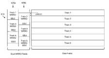
- FIG. 3illustrates an example of a conventional WRRO layout on a disk. More particularly, FIG. 3 shows an example of data fields for six data tracks labeled Track 1 to Track 6 . The data field for each track includes one or more data sectors and corresponds to a portion of the track between adjacent servo wedges. FIG. 3 also shows an example of six WRRO fields 335 - 1 to 335 - 6 , where each WRRO field 335 - 1 to 335 - 6 corresponds to one of the data tracks in FIG. 3 . Each WRRO field 335 - 1 to 335 - 6 may include one or more WRRO compensation values to compensate for repeatable runout for the corresponding data track. For example, WRRO field 335 - 1 may include one or more WRRO compensation values for Track 1 .
- the WRRO fields 335 - 1 to 335 - 6 shown in FIG. 3are located in a servo wedge.
- each WRRO field 335 - 1 to 335 - 6has a width that is equal to the width of the corresponding track in the radial direction.
- each WRRO field 335 - 1 to 335 - 6is centered with the corresponding track in the radial direction.
- a WRRO field 335 - 1 to 335 - 6may be centered with or offset from the corresponding track in the radial direction depending on whether the WRRO field includes read WRRO compensation values or write WRRO compensation values, as discussed further below.
- Read WRRO compensation valuesare used to compensate for repeatable runout for a track during a read operation.
- An WRRO field including read compensation valuesmay be centered with the corresponding track because the same reader of the head 50 may be used to both read the read WRRO compensation values from the WRRO field and read data from the corresponding track.
- Write WRRO compensation valuesare used to compensate for repeatable runout for a track during a write operation.
- An WRRO field including write WRRO compensation valuesmay be offset from the corresponding track because the reader of the head 50 used to read the write WRRO compensation values from the WRRO field is offset from the writer of the head 50 used to write data on the corresponding track.
- the WRRO fieldmay be offset from the corresponding track in the radial direction to account for the reader/writer offset.
- Read and write WRRO compensation valuesmay be written on the disk in alternating servo wedges.
- read WRRO fields including read WRRO compensation valuesmay be written in odd servo wedges
- write WRRO fields including write WRRO compensation valuesmay be written in even servo wedges.
- each read WRRO fieldmay include read WRRO compensation values for a portion of the corresponding track extending to the next two servo wedges. This is because the read WRRO fields for a track are written in every other servo wedge.
- each write WRRO fieldmay include write WRRO compensation values for a portion of the corresponding track extending to the next two servo wedges.
- WRRO fieldmay refer to either a read WRRO field or a write WRRO field.
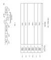
- FIG. 4shows an example of the WRRO fields 335 - 1 to 335 - 6 in the conventional WRRO layout in more detail.
- each WRRO field 335 - 1 to 335 - 6may include a WRRO preamble and two WRRO compensation values W 1 and W 2 .
- the two WRRO compensation values W 1 and W 2provide WRRO compensation for a portion of the corresponding track extending to the next two servo wedges, as discussed above.
- the WRRO preamble for each WRRO field 335 - 1 to 335 - 6provides timing information that allows the controller 10 to synchronize with the timing of the bits of the WRRO compensation values W 1 and W 2 in order to read the WRRO compensation values W 1 and W 2 .
- the WRRO preambleshould not be confused with the preamble 215 of the corresponding servo sector.
- FIGS. 5A-5Bshow the progression of a shingle write on the disk 60 .
- the head 50writes data to the disk 60 in a first wide circular band 510 a .
- the head 50is offset by a small amount from its position in FIG. 5A .
- the head 50then writes subsequent data to the disk 60 in a second wide circular band 510 b .
- the second wide circular band 510 boverlaps and overwrites most of the first wide circular band 510 a , leaving a narrow portion of the wide first circular band 510 a that defines a narrow track 515 . This process may be repeated to write a sequence of data on the disk 60 .
- the width of the track 515 in shingle writingmay be defined by the offset of the head position (A head position in FIG. 5B ) between consecutive track writes.
- datais typically sequentially written to the disk 60 in one direction (from the outer diameter (OD) to the inner diameter (ID) of the disk 60 or the opposite direction).
- shingle writingallows the disk drive 100 to write narrower tracks for given head dimensions. This allows the disk drive 100 to achieve much higher tracks per inch (TPI) and therefore increase the storage capacity of the disk 60 .
- the narrow tracksincrease the effects of adjacent track interference (ATI) on data integrity.
- ATIadjacent track interference
- a trackmay be written only once or a limited number of times to ensure a certain level of data integrity.
- This constraintmay severely impact the WRRO off track read capability (OTRC) of the disk drive 100 using the conventional WRRO layout. This is because WRRO values may be written on a track multiple times during WRRO retry, which increases data degradation due to ATI.
- FIG. 6shows an alternating WRRO layout 610 according to an embodiment of the present invention that may be used to improve the WRRO OTRC of a disk drive.
- the alternating WRRO layout 610is shown for one servo wedge in FIG. 6 .
- the WRRO layout 610comprises a first set of WRRO fields 620 a and a second set of WRRO fields 620 b , in which the first set of WRRO fields 620 a is offset from the second set of WRRO fields 620 b in a circumferential direction of the disk.
- Each set of WRRO fields 620 a and 620 bmay include WRRO fields arranged along a radial direction of the disk, as shown in the example in FIG. 6 .
- the first and second sets of WRRO fields 620 a and 620 bmay each include WRRO fields for every other track.
- the first set of WRRO fields 620 amay include WRRO fields 635 - 1 , 635 - 3 and 635 - 5 for odd tracks
- the second set of WRRO fields 530may include WRRO fields 635 - 2 , 635 - 4 and 635 - 6 for even tracks, as shown in FIG. 6 .
- each set of WRRO fields 620 a and 620 bincludes WRRO fields for half of the data tracks. This allows the WRRO fields in each set to have a width that is wider than the width of the corresponding track in the radial direction.
- each WRRO fieldhas a width that is approximately twice the width of the corresponding track in the radial direction.
- the wider WRRO field width in the radial directionincreases the WRRO OTRC of the disk drive 100 .
- the first set of WRRO fields 620 ais radially offset from the second set of WRRO fields 620 b by one track width in the example in FIG. 6 .
- WRRO field widthis approximately twice the track width in the example in FIG. 6
- WRRO field widthmay be any width that is wider than the track width.
- each WRRO fieldmay have a width that is 25% to 100% greater than the width of the corresponding track.
- the WRRO field widthis less than twice the track width, there may be a space between adjacent WRRO fields in the same set.
- Each WRRO fieldmay be centered with the corresponding track in the radial direction.
- WRRO field 635 - 2is approximately centered with Track 2 in the radial direction.
- WRRO field 635 - 3is approximately centered with Track 3 in the radial direction.
- the WRRO fieldsmay comprise read WRRO fields.
- the WRRO fieldsmay be offset from the corresponding tracks in the radial direction by a reader/writer offset, as discussed above.
- FIG. 6shows the write offset (A WRRO) in the radial direction between an WRRO field and the corresponding track.
- the write offsetmay correspond to the offset between the head position for writing the WRRO field and the head position for writing the corresponding track.
- the write offsetis approximately equal to half a track width.
- the write offsetmay be adjusted to account for reader/writer offset, as discussed above.
- the write offset (A WRRO)may also be adjusted, for example, based on the write offset that achieves the best WRRO OTRC for a given WRRO field width.
- the alternating WRRO layoutallows the WRRO fields 635 - 1 to 635 - 6 to have wider widths in the radial direction while allowing the data tracks to remain narrow for increased data storage capacity.
- the wider widths of the WRRO fields 635 - 1 to 635 - 6increase the WRRO OTRC of the disk drive 100 , thereby increasing the likelihood that the controller 10 accurately reads the WRRO compensation values from the WRRO fields.
- the read WRRO compensation valuesallow the controller 10 to compensate for repeatable runout, keeping the head 50 on track.
- FIG. 7shows an alternating WRRO layout 710 according to an embodiment of the present.
- the alternating WRRO layout 710is shown for one servo wedge in FIG. 7 .
- the WRRO layout 710comprises a first set of WRRO fields 720 a , a second set of WRRO fields 720 b , and a third set of WRRO fields 720 c that are offset from one another in the circumferential direction.
- the first, second and third sets of WRRO fields 720 a , 720 b and 720 cmay each include WRRO fields for every third track. In the example shown in FIG.
- the first set of WRRO fields 720 aincludes WRRO fields 735 - 1 and 735 - 4 for the tracks labeled Track 1 and Track 4
- the second set of WRRO fields 720 bincludes WRRO fields 735 - 2 and 735 - 5 for the tracks labeled Track 2 and Track 5
- the third set of WRRO fields 720 cincludes WRRO fields 735 - 3 and 735 - 6 for the tracks labeled Track 3 and Track 6 .
- each set of WRRO fields 720 a , 720 b and 720 cincludes WRRO fields for a third of the data tracks.
- each WRRO field in each sethas a width that is approximately three times the width of the corresponding track in the radial direction.
- the wider widths of the WRRO fields in the radial directionincreases the WRRO OTRC of the disk drive 100 .
- the alternating WRRO layout 610 in the example in FIG. 7allows the width of the WRRO fields to be wider (up to three track widths), thereby increasing the WRRO OTRC of the disk.
- a tradeoff of the increased WRRO OTRCis reduced format efficiency because more space is needed on the disk 60 for the wider WRRO fields.
- An alternating WRRO layoutmay include WRRO fields of any width.
- the alternating WRRO layout for each servo wedgemay comprise M sets of WRRO fields arranged in the circumferential direction of the disk, where each WRRO field has a width of up to M track widths in the radial direction of the disk.
- Each of the M sets of WRRO fieldsmay include WRRO fields for 1/M of the tracks.
- the WRRO compensation values for Track Kmay be located in the mod(K, M) WRRO field in the corresponding set of WRRO fields.
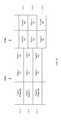
- FIG. 8shows an example of the WRRO fields 635 - 1 to 635 - 6 in the dual alternating WRRO layout according to an embodiment of the present invention.
- each WRRO field 635 - 1 to 635 - 6may include a WRRO preamble and two WRRO compensation values W 1 and W 2 .
- the two WRRO compensation values W 1 and W 2provide WRRO compensation for a portion of the corresponding track extending to the next two servo wedges, as discussed above.
- each WRRO field 635 - 1 to 635 - 6provides timing information that allows the controller 10 to synchronize with the timing of the bits of the WRRO compensation values W 1 and W 2 in order to read the WRRO compensation values W 1 and W 2 .
- each WRRO field 635 - 1 to 635 - 6has a separate preamble.
- the WRRO fields 635 - 1 to 635 - 6may be written using shingle or non-shingle writing.
- the WRRO fields 635 - 1 to 635 - 6 and the tracksmay both be written using shingle writing.
- the offset of the head position between consecutive track writesdetermines the width of a track in shingle writing.
- the width of the WRRO fields 635 - 1 to 635 - 6may be made wider than the width of the tracks by using a larger head offset for the shingle writing of the WRRO fields.
- FIG. 9shows an example of the WRRO layout with shared preambles to reduce servo overhead according to an embodiment of the present invention.
- the WRRO layoutcomprises one WRRO preamble for each pair of WRRO fields 635 - 1 to 635 - 6 instead of a separate WRRO preamble for each WRRO field 635 - 1 to 635 - 6 .
- the controller 10when the controller 10 reads WRRO field 635 - 2 for Track 2 , the controller 10 may read either the WRRO preamble in WRRO field 635 - 1 or WRRO field 635 - 3 for timing information to read the WRRO compensation values W 1 and W 2 in WRRO field 635 - 2 .
- Which WRRO preamble is readmay depend on the direction the head 50 is offset from the centerline of Track 2 .
- the timing information in WRRO fields 635 - 1 to 635 - 3may be close to the timing of the WRRO compensation values W 1 and W 2 in WRRO field 635 - 2 so that the WRRO preamble in either WRRO field 635 - 1 and 635 - 3 can be use to provide timing for WRRO field 635 - 2 .
- the shared preamblesreduce the space needed on the disk for the WRRO field, thereby reducing servo overhead compared with the case where each WRRO field has a separate WRRO preamble.
- the WRRO fields 635 - 1 to 635 - 6may be written using shingle writing. An example of this is shown in FIG. 10 .
- the WRRO layoutis written in bands 1010 - 1 to 1010 - 5 that are sequentially written on the disk 60 in the radial direction, in which the head 50 is offset by a small amount between writes for adjacent bands 1010 - 1 to 1010 - 6 .
- the head 50may write a portion of a WRRO field in the first set 620 a and a portion of a WRRO field in second set 620 b .
- the head 50writes a bottom portion of WRRO field 635 - 1 and a top portion of WRRO field 635 - 2
- the head 50writes a top portion of WRRO field 635 - 3 and a bottom portion of WRRO field 635 - 2 , and so on.
- FIG. 11is a flow diagram of a method of servo writing a disk comprising a plurality of data tracks 4 and servo wedges 22 0 - 22 N according to an embodiment of the present invention.
- WRRO compensation valuesare generated for sequential data tracks (e.g., Tracks 1 to Tracks 6 shown in FIG. 6 ).
- the WRRO compensation valuesmay be determined in a learning process or any suitable technique known in the art.
- step 1120for each servo wedge, the corresponding WRRO compensation values for the sequential data tracks are written in M sets of WRRO fields in an alternating fashion.
- the WRRO compensation values for the odd tracksmay be written to the first set of WRRO fields 620 a and the WRRO compensation values for the even tracks may be written to the second set of WRRO fields 620 b .
- the WRRO compensation values for the sequential data tracksmay be written to the first, second and third sets of WRRO fields 720 a , 720 b and 720 c in an alternating fashion.
- each set of WRRO fields 720 a , 720 b and 720 creceives WRRO compensation values for every third data track.
- the M sets of WRRO fields in a servo wedgemay be arranged in a circumferential direction of the disk so that each set is offset from the other sets in the circumferential direction.
- the WRRO fields in each setmay be arranged along the radial direction of the disk, as shown in the examples in FIGS. 6 and 7 .
Landscapes
- Moving Of The Head To Find And Align With The Track (AREA)
Abstract
Description
Claims (20)
Priority Applications (1)
| Application Number | Priority Date | Filing Date | Title |
|---|---|---|---|
| US13/167,062US8693134B1 (en) | 2011-06-23 | 2011-06-23 | Alternating wedge repeatable runout (WRRO) pattern |
Applications Claiming Priority (1)
| Application Number | Priority Date | Filing Date | Title |
|---|---|---|---|
| US13/167,062US8693134B1 (en) | 2011-06-23 | 2011-06-23 | Alternating wedge repeatable runout (WRRO) pattern |
Publications (1)
| Publication Number | Publication Date |
|---|---|
| US8693134B1true US8693134B1 (en) | 2014-04-08 |
Family
ID=50391844
Family Applications (1)
| Application Number | Title | Priority Date | Filing Date |
|---|---|---|---|
| US13/167,062Active2032-01-26US8693134B1 (en) | 2011-06-23 | 2011-06-23 | Alternating wedge repeatable runout (WRRO) pattern |
Country Status (1)
| Country | Link |
|---|---|
| US (1) | US8693134B1 (en) |
Cited By (117)
| Publication number | Priority date | Publication date | Assignee | Title |
|---|---|---|---|---|
| US8824081B1 (en) | 2012-03-13 | 2014-09-02 | Western Digital Technologies, Inc. | Disk drive employing radially coherent reference pattern for servo burst demodulation and fly height measurement |
| US8879191B1 (en) | 2012-11-14 | 2014-11-04 | Western Digital Technologies, Inc. | Disk drive modifying rotational position optimization algorithm to achieve target performance for limited stroke |
| US8891191B1 (en) | 2014-05-06 | 2014-11-18 | Western Digital Technologies, Inc. | Data storage device initializing read signal gain to detect servo seed pattern |
| US8891194B1 (en) | 2013-05-14 | 2014-11-18 | Western Digital Technologies, Inc. | Disk drive iteratively adapting correction value that compensates for non-linearity of head |
| US8896957B1 (en) | 2013-05-10 | 2014-11-25 | Western Digital Technologies, Inc. | Disk drive performing spiral scan of disk surface to detect residual data |
| US8902538B1 (en) | 2013-03-29 | 2014-12-02 | Western Digital Technologies, Inc. | Disk drive detecting crack in microactuator |
| US8902539B1 (en) | 2014-05-13 | 2014-12-02 | Western Digital Technologies, Inc. | Data storage device reducing seek power consumption |
| US8913342B1 (en) | 2014-03-21 | 2014-12-16 | Western Digital Technologies, Inc. | Data storage device adjusting range of microactuator digital-to-analog converter based on operating temperature |
| US8917474B1 (en) | 2011-08-08 | 2014-12-23 | Western Digital Technologies, Inc. | Disk drive calibrating a velocity profile prior to writing a spiral track |
| US8917475B1 (en) | 2013-12-20 | 2014-12-23 | Western Digital Technologies, Inc. | Disk drive generating a disk locked clock using radial dependent timing feed-forward compensation |
| US8922940B1 (en) | 2014-05-27 | 2014-12-30 | Western Digital Technologies, Inc. | Data storage device reducing spindle motor voltage boost during power failure |
| US8922931B1 (en) | 2013-05-13 | 2014-12-30 | Western Digital Technologies, Inc. | Disk drive releasing variable amount of buffered write data based on sliding window of predicted servo quality |
| US8922938B1 (en) | 2012-11-02 | 2014-12-30 | Western Digital Technologies, Inc. | Disk drive filtering disturbance signal and error signal for adaptive feed-forward compensation |
| US8922937B1 (en) | 2012-04-19 | 2014-12-30 | Western Digital Technologies, Inc. | Disk drive evaluating multiple vibration sensor outputs to enable write-protection |
| US8929022B1 (en) | 2012-12-19 | 2015-01-06 | Western Digital Technologies, Inc. | Disk drive detecting microactuator degradation by evaluating frequency component of servo signal |
| US8929021B1 (en) | 2012-03-27 | 2015-01-06 | Western Digital Technologies, Inc. | Disk drive servo writing from spiral tracks using radial dependent timing feed-forward compensation |
| US8934186B1 (en) | 2014-03-26 | 2015-01-13 | Western Digital Technologies, Inc. | Data storage device estimating servo zone to reduce size of track address |
| US8937784B1 (en) | 2012-08-01 | 2015-01-20 | Western Digital Technologies, Inc. | Disk drive employing feed-forward compensation and phase shift compensation during seek settling |
| US8941939B1 (en) | 2013-10-24 | 2015-01-27 | Western Digital Technologies, Inc. | Disk drive using VCM BEMF feed-forward compensation to write servo data to a disk |
| US8941945B1 (en) | 2014-06-06 | 2015-01-27 | Western Digital Technologies, Inc. | Data storage device servoing heads based on virtual servo tracks |
| US8947819B1 (en) | 2012-08-28 | 2015-02-03 | Western Digital Technologies, Inc. | Disk drive implementing hysteresis for primary shock detector based on a more sensitive secondary shock detector |
| US8953278B1 (en) | 2011-11-16 | 2015-02-10 | Western Digital Technologies, Inc. | Disk drive selecting disturbance signal for feed-forward compensation |
| US8953271B1 (en) | 2013-05-13 | 2015-02-10 | Western Digital Technologies, Inc. | Disk drive compensating for repeatable run out selectively per zone |
| US8958169B1 (en) | 2014-06-11 | 2015-02-17 | Western Digital Technologies, Inc. | Data storage device re-qualifying state estimator while decelerating head |
| US8970979B1 (en) | 2013-12-18 | 2015-03-03 | Western Digital Technologies, Inc. | Disk drive determining frequency response of actuator near servo sample frequency |
| US8982501B1 (en) | 2014-09-22 | 2015-03-17 | Western Digital Technologies, Inc. | Data storage device compensating for repeatable disturbance when commutating a spindle motor |
| US8982490B1 (en) | 2014-04-24 | 2015-03-17 | Western Digital Technologies, Inc. | Data storage device reading first spiral track while simultaneously writing second spiral track |
| US8995082B1 (en) | 2011-06-03 | 2015-03-31 | Western Digital Technologies, Inc. | Reducing acoustic noise in a disk drive when exiting idle mode |
| US8995075B1 (en) | 2012-06-21 | 2015-03-31 | Western Digital Technologies, Inc. | Disk drive adjusting estimated servo state to compensate for transient when crossing a servo zone boundary |
| US9001454B1 (en) | 2013-04-12 | 2015-04-07 | Western Digital Technologies, Inc. | Disk drive adjusting phase of adaptive feed-forward controller when reconfiguring servo loop |
| US9007714B1 (en) | 2014-07-18 | 2015-04-14 | Western Digital Technologies Inc. | Data storage device comprising slew rate anti-windup compensation for microactuator |
| US9013824B1 (en) | 2014-06-04 | 2015-04-21 | Western Digital Technologies, Inc. | Data storage device comprising dual read sensors and dual servo channels to improve servo demodulation |
| US9013825B1 (en) | 2014-03-24 | 2015-04-21 | Western Digital Technologies, Inc. | Electronic system with vibration management mechanism and method of operation thereof |
| US9025269B1 (en) | 2014-01-02 | 2015-05-05 | Western Digital Technologies, Inc. | Disk drive compensating for cycle slip of disk locked clock when reading mini-wedge |
| US9026728B1 (en) | 2013-06-06 | 2015-05-05 | Western Digital Technologies, Inc. | Disk drive applying feed-forward compensation when writing consecutive data tracks |
| US9047901B1 (en) | 2013-05-28 | 2015-06-02 | Western Digital Technologies, Inc. | Disk drive measuring spiral track error by measuring a slope of a spiral track across a disk radius |
| US9047919B1 (en) | 2013-03-12 | 2015-06-02 | Western Digitial Technologies, Inc. | Disk drive initializing servo read channel by reading data preceding servo preamble during access operation |
| US9047932B1 (en) | 2014-03-21 | 2015-06-02 | Western Digital Technologies, Inc. | Data storage device adjusting a power loss threshold based on samples of supply voltage |
| US9053712B1 (en) | 2014-05-07 | 2015-06-09 | Western Digital Technologies, Inc. | Data storage device reading servo sector while writing data sector |
| US9053727B1 (en) | 2014-06-02 | 2015-06-09 | Western Digital Technologies, Inc. | Disk drive opening spiral crossing window based on DC and AC spiral track error |
| US9053726B1 (en) | 2014-01-29 | 2015-06-09 | Western Digital Technologies, Inc. | Data storage device on-line adapting disturbance observer filter |
| US9058826B1 (en) | 2014-02-13 | 2015-06-16 | Western Digital Technologies, Inc. | Data storage device detecting free fall condition from disk speed variations |
| US9058827B1 (en) | 2013-06-25 | 2015-06-16 | Western Digitial Technologies, Inc. | Disk drive optimizing filters based on sensor signal and disturbance signal for adaptive feed-forward compensation |
| US9058834B1 (en) | 2013-11-08 | 2015-06-16 | Western Digital Technologies, Inc. | Power architecture for low power modes in storage devices |
| US9064537B1 (en) | 2013-09-13 | 2015-06-23 | Western Digital Technologies, Inc. | Disk drive measuring radial offset between heads by detecting a difference between ramp contact |
| US9076473B1 (en) | 2014-08-12 | 2015-07-07 | Western Digital Technologies, Inc. | Data storage device detecting fly height instability of head during load operation based on microactuator response |
| US9076472B1 (en) | 2014-08-21 | 2015-07-07 | Western Digital (Fremont), Llc | Apparatus enabling writing servo data when disk reaches target rotation speed |
| US9076471B1 (en) | 2013-07-31 | 2015-07-07 | Western Digital Technologies, Inc. | Fall detection scheme using FFS |
| US9076490B1 (en) | 2012-12-12 | 2015-07-07 | Western Digital Technologies, Inc. | Disk drive writing radial offset spiral servo tracks by reading spiral seed tracks |
| US9093105B2 (en) | 2011-12-09 | 2015-07-28 | Western Digital Technologies, Inc. | Disk drive charging capacitor using motor supply voltage during power failure |
| US9099147B1 (en) | 2014-09-22 | 2015-08-04 | Western Digital Technologies, Inc. | Data storage device commutating a spindle motor using closed-loop rotation phase alignment |
| US9111575B1 (en) | 2014-10-23 | 2015-08-18 | Western Digital Technologies, Inc. | Data storage device employing adaptive feed-forward control in timing loop to compensate for vibration |
| US9129630B1 (en) | 2014-12-16 | 2015-09-08 | Western Digital Technologies, Inc. | Data storage device employing full servo sectors on first disk surface and mini servo sectors on second disk surface |
| US9142225B1 (en) | 2014-03-21 | 2015-09-22 | Western Digital Technologies, Inc. | Electronic system with actuator control mechanism and method of operation thereof |
| US9141177B1 (en) | 2014-03-21 | 2015-09-22 | Western Digital Technologies, Inc. | Data storage device employing glitch compensation for power loss detection |
| US9142235B1 (en) | 2009-10-27 | 2015-09-22 | Western Digital Technologies, Inc. | Disk drive characterizing microactuator by injecting sinusoidal disturbance and evaluating feed-forward compensation values |
| US9142249B1 (en) | 2013-12-06 | 2015-09-22 | Western Digital Technologies, Inc. | Disk drive using timing loop control signal for vibration compensation in servo loop |
| US9147418B1 (en) | 2013-06-20 | 2015-09-29 | Western Digital Technologies, Inc. | Disk drive compensating for microactuator gain variations |
| US9147428B1 (en) | 2013-04-24 | 2015-09-29 | Western Digital Technologies, Inc. | Disk drive with improved spin-up control |
| US9153283B1 (en) | 2014-09-30 | 2015-10-06 | Western Digital Technologies, Inc. | Data storage device compensating for hysteretic response of microactuator |
| US9165583B1 (en) | 2014-10-29 | 2015-10-20 | Western Digital Technologies, Inc. | Data storage device adjusting seek profile based on seek length when ending track is near ramp |
| US9171567B1 (en) | 2014-05-27 | 2015-10-27 | Western Digital Technologies, Inc. | Data storage device employing sliding mode control of spindle motor |
| US9171568B1 (en) | 2014-06-25 | 2015-10-27 | Western Digital Technologies, Inc. | Data storage device periodically re-initializing spindle motor commutation sequence based on timing data |
| US9208815B1 (en) | 2014-10-09 | 2015-12-08 | Western Digital Technologies, Inc. | Data storage device dynamically reducing coast velocity during seek to reduce power consumption |
| US9208810B1 (en) | 2014-04-24 | 2015-12-08 | Western Digital Technologies, Inc. | Data storage device attenuating interference from first spiral track when reading second spiral track |
| US9208808B1 (en) | 2014-04-22 | 2015-12-08 | Western Digital Technologies, Inc. | Electronic system with unload management mechanism and method of operation thereof |
| US9214175B1 (en) | 2015-03-16 | 2015-12-15 | Western Digital Technologies, Inc. | Data storage device configuring a gain of a servo control system for actuating a head over a disk |
| US9230592B1 (en) | 2014-12-23 | 2016-01-05 | Western Digital Technologies, Inc. | Electronic system with a method of motor spindle bandwidth estimation and calibration thereof |
| US9230593B1 (en) | 2014-12-23 | 2016-01-05 | Western Digital Technologies, Inc. | Data storage device optimizing spindle motor power when transitioning into a power failure mode |
| US9245540B1 (en) | 2014-10-29 | 2016-01-26 | Western Digital Technologies, Inc. | Voice coil motor temperature sensing circuit to reduce catastrophic failure due to voice coil motor coil shorting to ground |
| US9245560B1 (en) | 2015-03-09 | 2016-01-26 | Western Digital Technologies, Inc. | Data storage device measuring reader/writer offset by reading spiral track and concentric servo sectors |
| US9245577B1 (en) | 2015-03-26 | 2016-01-26 | Western Digital Technologies, Inc. | Data storage device comprising spindle motor current sensing with supply voltage noise attenuation |
| US9251823B1 (en) | 2014-12-10 | 2016-02-02 | Western Digital Technologies, Inc. | Data storage device delaying seek operation to avoid thermal asperities |
| US9269386B1 (en) | 2014-01-29 | 2016-02-23 | Western Digital Technologies, Inc. | Data storage device on-line adapting disturbance observer filter |
| US9286927B1 (en) | 2014-12-16 | 2016-03-15 | Western Digital Technologies, Inc. | Data storage device demodulating servo burst by computing slope of intermediate integration points |
| US9286925B1 (en) | 2015-03-26 | 2016-03-15 | Western Digital Technologies, Inc. | Data storage device writing multiple burst correction values at the same radial location |
| US9343102B1 (en) | 2015-03-25 | 2016-05-17 | Western Digital Technologies, Inc. | Data storage device employing a phase offset to generate power from a spindle motor during a power failure |
| US9343094B1 (en)* | 2015-03-26 | 2016-05-17 | Western Digital Technologies, Inc. | Data storage device filtering burst correction values before downsampling the burst correction values |
| US9350278B1 (en) | 2014-06-13 | 2016-05-24 | Western Digital Technologies, Inc. | Circuit technique to integrate voice coil motor support elements |
| US9349400B1 (en)* | 2015-06-25 | 2016-05-24 | HGST Netherlands B.V. | Magnetic recording disk drive with adjustable data track pitch and compensation for repeatable runout (RRO) |
| US9349401B1 (en) | 2014-07-24 | 2016-05-24 | Western Digital Technologies, Inc. | Electronic system with media scan mechanism and method of operation thereof |
| US9355667B1 (en) | 2014-11-11 | 2016-05-31 | Western Digital Technologies, Inc. | Data storage device saving absolute position at each servo wedge for previous write operations |
| US9355676B1 (en) | 2015-03-25 | 2016-05-31 | Western Digital Technologies, Inc. | Data storage device controlling amplitude and phase of driving voltage to generate power from a spindle motor |
| US9361939B1 (en) | 2014-03-10 | 2016-06-07 | Western Digital Technologies, Inc. | Data storage device characterizing geometry of magnetic transitions |
| US9396751B1 (en) | 2015-06-26 | 2016-07-19 | Western Digital Technologies, Inc. | Data storage device compensating for fabrication tolerances when measuring spindle motor current |
| US9407015B1 (en) | 2014-12-29 | 2016-08-02 | Western Digital Technologies, Inc. | Automatic power disconnect device |
| US9418689B2 (en) | 2014-10-09 | 2016-08-16 | Western Digital Technologies, Inc. | Data storage device generating an operating seek time profile as a function of a base seek time profile |
| US9424868B1 (en) | 2015-05-12 | 2016-08-23 | Western Digital Technologies, Inc. | Data storage device employing spindle motor driving profile during seek to improve power performance |
| US9424871B1 (en) | 2012-09-13 | 2016-08-23 | Western Digital Technologies, Inc. | Disk drive correcting an error in a detected gray code |
| US9437231B1 (en) | 2015-09-25 | 2016-09-06 | Western Digital Technologies, Inc. | Data storage device concurrently controlling and sensing a secondary actuator for actuating a head over a disk |
| US9437237B1 (en) | 2015-02-20 | 2016-09-06 | Western Digital Technologies, Inc. | Method to detect power loss through data storage device spindle speed |
| US9454212B1 (en) | 2014-12-08 | 2016-09-27 | Western Digital Technologies, Inc. | Wakeup detector |
| US9471072B1 (en) | 2013-11-14 | 2016-10-18 | Western Digital Technologies, Inc | Self-adaptive voltage scaling |
| US9484733B1 (en) | 2013-09-11 | 2016-11-01 | Western Digital Technologies, Inc. | Power control module for data storage device |
| US9502062B1 (en) | 2015-10-30 | 2016-11-22 | Seagate Technology Llc | Using two or more offset repeatable runout correction values for a virtual track of a magnetic disk |
| US9508370B1 (en)* | 2016-05-26 | 2016-11-29 | Seagate Technology Llc | Repeated runout (RRO) compensation for alternating tracks in an interlaced magnetic recording system |
| US9542966B1 (en) | 2015-07-09 | 2017-01-10 | Western Digital Technologies, Inc. | Data storage devices and methods with frequency-shaped sliding mode control |
| US9564162B1 (en) | 2015-12-28 | 2017-02-07 | Western Digital Technologies, Inc. | Data storage device measuring resonant frequency of a shock sensor by applying differential excitation and measuring oscillation |
| US9581978B1 (en) | 2014-12-17 | 2017-02-28 | Western Digital Technologies, Inc. | Electronic system with servo management mechanism and method of operation thereof |
| US9620160B1 (en) | 2015-12-28 | 2017-04-11 | Western Digital Technologies, Inc. | Data storage device measuring resonant frequency of a shock sensor by inserting the shock sensor into an oscillator circuit |
| US9799360B2 (en)* | 2016-03-10 | 2017-10-24 | Kabushiki Kaisha Toshiba | Magnetic disk device and correction method of head position |
| US9823294B1 (en) | 2013-10-29 | 2017-11-21 | Western Digital Technologies, Inc. | Negative voltage testing methodology and tester |
| US9886285B2 (en) | 2015-03-31 | 2018-02-06 | Western Digital Technologies, Inc. | Communication interface initialization |
| US9899834B1 (en) | 2015-11-18 | 2018-02-20 | Western Digital Technologies, Inc. | Power control module using protection circuit for regulating backup voltage to power load during power fault |
| US9959204B1 (en) | 2015-03-09 | 2018-05-01 | Western Digital Technologies, Inc. | Tracking sequential ranges of non-ordered data |
| US10332557B1 (en) | 2018-09-13 | 2019-06-25 | Seagate Technology Llc | Multitrack servo marks with perpendicular and longitudinal magnetic fields |
| US10490219B1 (en) | 2018-09-06 | 2019-11-26 | Seagate Technology Llc | Using signals from perpendicular and longitudinal multitrack magnetic fields for error recovery and/or servo control |
| US10607645B1 (en) | 2019-06-28 | 2020-03-31 | Western Digital Technologies, Inc. | Data storage device generating PES RRO and data sector squeeze RRO for a plurality of zones |
| US10699745B1 (en) | 2019-06-28 | 2020-06-30 | Western Digital Technologies, Inc. | Data storage device defining track trajectory to reduce AC track squeeze |
| US10748568B1 (en) | 2019-08-06 | 2020-08-18 | Western Digital Technologies, Inc. | Data storage device employing dynamic track trajectories |
| US20230282237A1 (en)* | 2022-03-02 | 2023-09-07 | Western Digital Technologies, Inc. | Data storage device integrating wedge repeatable runout (wrro) learning into data recovery procedure (drp) |
| US12347453B1 (en) | 2024-05-01 | 2025-07-01 | Western Digital Technologies, Inc. | Wedge repeatable runout correction for interleaved servo patterns in a data storage device |
| US12354632B1 (en) | 2024-03-05 | 2025-07-08 | Western Digital Technologies, Inc. | Parallel self-servo write in a data storage device |
| US12361968B1 (en) | 2024-03-05 | 2025-07-15 | Western Digital Technologies, Inc. | Servo interface circuitry for parallel self-servo write |
| US12361965B1 (en) | 2024-03-05 | 2025-07-15 | Western Digital Technologies, Inc. | Preamplifier circuit for parallel self-servo write |
| US12361970B1 (en) | 2024-03-05 | 2025-07-15 | Western Digital Technologies, Inc. | Parallel self-servo write circuitry in a data storage device |
| US12394435B1 (en) | 2024-05-01 | 2025-08-19 | Western Digital Technologies, Inc. | Interleaved servo patterns in a data storage device |
Citations (10)
| Publication number | Priority date | Publication date | Assignee | Title |
|---|---|---|---|---|
| US20020109933A1 (en)* | 2001-02-15 | 2002-08-15 | Fujitsu Limited | Servo pattern deviation correcting method and disk apparatus using the same |
| US6775091B1 (en) | 2001-02-28 | 2004-08-10 | Marvell International Ltd. | Repeatable run-out compensation for disk drive |
| US20050071537A1 (en) | 2003-09-26 | 2005-03-31 | Hitachi Global Storage Technologies | Log-structured file system for disk drives with shingled writing |
| US6999266B1 (en)* | 2002-12-30 | 2006-02-14 | Matsushita Electric Industrial Co., Ltd. | Methods for WORF improvement |
| US7082007B2 (en) | 2000-09-27 | 2006-07-25 | Seagate Technology Llc | Method to achieve higher track density by allowing only one-sided track encroachment |
| US20060232874A1 (en) | 2005-04-13 | 2006-10-19 | Hitachi Global Storage Technologies Netherlands B. V. | Disk drive with enhanced storage capacity increase ratio |
| US7133241B2 (en) | 2005-04-11 | 2006-11-07 | Hitachi Global Storage Technologies Netherlands B.V. | Method and apparatus for optimizing record quality with varying track and linear density by allowing overlapping data tracks |
| US20070223132A1 (en) | 2006-03-24 | 2007-09-27 | Hitachi Global Storage Technologies Netherlands B.V. | Information recording apparatus |
| US7564637B2 (en)* | 2005-09-14 | 2009-07-21 | Fujitsu Limited | Storage media having areas for storing data for correcting servo information errors |
| US7675700B2 (en)* | 2007-03-26 | 2010-03-09 | Hitachi Global Storage Technologies Netherlands B.V. | Disk drive device and method for production thereof |
- 2011
- 2011-06-23USUS13/167,062patent/US8693134B1/enactiveActive
Patent Citations (11)
| Publication number | Priority date | Publication date | Assignee | Title |
|---|---|---|---|---|
| US7082007B2 (en) | 2000-09-27 | 2006-07-25 | Seagate Technology Llc | Method to achieve higher track density by allowing only one-sided track encroachment |
| US20020109933A1 (en)* | 2001-02-15 | 2002-08-15 | Fujitsu Limited | Servo pattern deviation correcting method and disk apparatus using the same |
| US6775091B1 (en) | 2001-02-28 | 2004-08-10 | Marvell International Ltd. | Repeatable run-out compensation for disk drive |
| US6999266B1 (en)* | 2002-12-30 | 2006-02-14 | Matsushita Electric Industrial Co., Ltd. | Methods for WORF improvement |
| US20050071537A1 (en) | 2003-09-26 | 2005-03-31 | Hitachi Global Storage Technologies | Log-structured file system for disk drives with shingled writing |
| US7133241B2 (en) | 2005-04-11 | 2006-11-07 | Hitachi Global Storage Technologies Netherlands B.V. | Method and apparatus for optimizing record quality with varying track and linear density by allowing overlapping data tracks |
| US20060232874A1 (en) | 2005-04-13 | 2006-10-19 | Hitachi Global Storage Technologies Netherlands B. V. | Disk drive with enhanced storage capacity increase ratio |
| US7486460B2 (en) | 2005-04-13 | 2009-02-03 | Hitachi Global Storage Technologies Netherlands B.V. | Disk drive with enhanced storage capacity increase ratio |
| US7564637B2 (en)* | 2005-09-14 | 2009-07-21 | Fujitsu Limited | Storage media having areas for storing data for correcting servo information errors |
| US20070223132A1 (en) | 2006-03-24 | 2007-09-27 | Hitachi Global Storage Technologies Netherlands B.V. | Information recording apparatus |
| US7675700B2 (en)* | 2007-03-26 | 2010-03-09 | Hitachi Global Storage Technologies Netherlands B.V. | Disk drive device and method for production thereof |
Cited By (124)
| Publication number | Priority date | Publication date | Assignee | Title |
|---|---|---|---|---|
| US9142235B1 (en) | 2009-10-27 | 2015-09-22 | Western Digital Technologies, Inc. | Disk drive characterizing microactuator by injecting sinusoidal disturbance and evaluating feed-forward compensation values |
| US8995082B1 (en) | 2011-06-03 | 2015-03-31 | Western Digital Technologies, Inc. | Reducing acoustic noise in a disk drive when exiting idle mode |
| US8917474B1 (en) | 2011-08-08 | 2014-12-23 | Western Digital Technologies, Inc. | Disk drive calibrating a velocity profile prior to writing a spiral track |
| US8953278B1 (en) | 2011-11-16 | 2015-02-10 | Western Digital Technologies, Inc. | Disk drive selecting disturbance signal for feed-forward compensation |
| US9390749B2 (en) | 2011-12-09 | 2016-07-12 | Western Digital Technologies, Inc. | Power failure management in disk drives |
| US9093105B2 (en) | 2011-12-09 | 2015-07-28 | Western Digital Technologies, Inc. | Disk drive charging capacitor using motor supply voltage during power failure |
| US8824081B1 (en) | 2012-03-13 | 2014-09-02 | Western Digital Technologies, Inc. | Disk drive employing radially coherent reference pattern for servo burst demodulation and fly height measurement |
| US8934191B1 (en) | 2012-03-27 | 2015-01-13 | Western Digital Technologies, Inc. | Disk drive generating a disk locked clock using radial dependent timing feed-forward compensation |
| US8929021B1 (en) | 2012-03-27 | 2015-01-06 | Western Digital Technologies, Inc. | Disk drive servo writing from spiral tracks using radial dependent timing feed-forward compensation |
| US8922937B1 (en) | 2012-04-19 | 2014-12-30 | Western Digital Technologies, Inc. | Disk drive evaluating multiple vibration sensor outputs to enable write-protection |
| US9454989B1 (en) | 2012-06-21 | 2016-09-27 | Western Digital Technologies, Inc. | Disk drive adjusting estimated servo state to compensate for transient when crossing a servo zone boundary |
| US8995075B1 (en) | 2012-06-21 | 2015-03-31 | Western Digital Technologies, Inc. | Disk drive adjusting estimated servo state to compensate for transient when crossing a servo zone boundary |
| US8937784B1 (en) | 2012-08-01 | 2015-01-20 | Western Digital Technologies, Inc. | Disk drive employing feed-forward compensation and phase shift compensation during seek settling |
| US8947819B1 (en) | 2012-08-28 | 2015-02-03 | Western Digital Technologies, Inc. | Disk drive implementing hysteresis for primary shock detector based on a more sensitive secondary shock detector |
| US9424871B1 (en) | 2012-09-13 | 2016-08-23 | Western Digital Technologies, Inc. | Disk drive correcting an error in a detected gray code |
| US8922938B1 (en) | 2012-11-02 | 2014-12-30 | Western Digital Technologies, Inc. | Disk drive filtering disturbance signal and error signal for adaptive feed-forward compensation |
| US8879191B1 (en) | 2012-11-14 | 2014-11-04 | Western Digital Technologies, Inc. | Disk drive modifying rotational position optimization algorithm to achieve target performance for limited stroke |
| US9076490B1 (en) | 2012-12-12 | 2015-07-07 | Western Digital Technologies, Inc. | Disk drive writing radial offset spiral servo tracks by reading spiral seed tracks |
| US8929022B1 (en) | 2012-12-19 | 2015-01-06 | Western Digital Technologies, Inc. | Disk drive detecting microactuator degradation by evaluating frequency component of servo signal |
| US9047919B1 (en) | 2013-03-12 | 2015-06-02 | Western Digitial Technologies, Inc. | Disk drive initializing servo read channel by reading data preceding servo preamble during access operation |
| US8902538B1 (en) | 2013-03-29 | 2014-12-02 | Western Digital Technologies, Inc. | Disk drive detecting crack in microactuator |
| US9001454B1 (en) | 2013-04-12 | 2015-04-07 | Western Digital Technologies, Inc. | Disk drive adjusting phase of adaptive feed-forward controller when reconfiguring servo loop |
| US9147428B1 (en) | 2013-04-24 | 2015-09-29 | Western Digital Technologies, Inc. | Disk drive with improved spin-up control |
| US8896957B1 (en) | 2013-05-10 | 2014-11-25 | Western Digital Technologies, Inc. | Disk drive performing spiral scan of disk surface to detect residual data |
| US8922931B1 (en) | 2013-05-13 | 2014-12-30 | Western Digital Technologies, Inc. | Disk drive releasing variable amount of buffered write data based on sliding window of predicted servo quality |
| US8953271B1 (en) | 2013-05-13 | 2015-02-10 | Western Digital Technologies, Inc. | Disk drive compensating for repeatable run out selectively per zone |
| US8891194B1 (en) | 2013-05-14 | 2014-11-18 | Western Digital Technologies, Inc. | Disk drive iteratively adapting correction value that compensates for non-linearity of head |
| US9047901B1 (en) | 2013-05-28 | 2015-06-02 | Western Digital Technologies, Inc. | Disk drive measuring spiral track error by measuring a slope of a spiral track across a disk radius |
| US9026728B1 (en) | 2013-06-06 | 2015-05-05 | Western Digital Technologies, Inc. | Disk drive applying feed-forward compensation when writing consecutive data tracks |
| US9147418B1 (en) | 2013-06-20 | 2015-09-29 | Western Digital Technologies, Inc. | Disk drive compensating for microactuator gain variations |
| US9058827B1 (en) | 2013-06-25 | 2015-06-16 | Western Digitial Technologies, Inc. | Disk drive optimizing filters based on sensor signal and disturbance signal for adaptive feed-forward compensation |
| US9076471B1 (en) | 2013-07-31 | 2015-07-07 | Western Digital Technologies, Inc. | Fall detection scheme using FFS |
| US9484733B1 (en) | 2013-09-11 | 2016-11-01 | Western Digital Technologies, Inc. | Power control module for data storage device |
| US9064537B1 (en) | 2013-09-13 | 2015-06-23 | Western Digital Technologies, Inc. | Disk drive measuring radial offset between heads by detecting a difference between ramp contact |
| US8941939B1 (en) | 2013-10-24 | 2015-01-27 | Western Digital Technologies, Inc. | Disk drive using VCM BEMF feed-forward compensation to write servo data to a disk |
| US9823294B1 (en) | 2013-10-29 | 2017-11-21 | Western Digital Technologies, Inc. | Negative voltage testing methodology and tester |
| US9058834B1 (en) | 2013-11-08 | 2015-06-16 | Western Digital Technologies, Inc. | Power architecture for low power modes in storage devices |
| US9471072B1 (en) | 2013-11-14 | 2016-10-18 | Western Digital Technologies, Inc | Self-adaptive voltage scaling |
| US9142249B1 (en) | 2013-12-06 | 2015-09-22 | Western Digital Technologies, Inc. | Disk drive using timing loop control signal for vibration compensation in servo loop |
| US8970979B1 (en) | 2013-12-18 | 2015-03-03 | Western Digital Technologies, Inc. | Disk drive determining frequency response of actuator near servo sample frequency |
| US8917475B1 (en) | 2013-12-20 | 2014-12-23 | Western Digital Technologies, Inc. | Disk drive generating a disk locked clock using radial dependent timing feed-forward compensation |
| US9025269B1 (en) | 2014-01-02 | 2015-05-05 | Western Digital Technologies, Inc. | Disk drive compensating for cycle slip of disk locked clock when reading mini-wedge |
| US9269386B1 (en) | 2014-01-29 | 2016-02-23 | Western Digital Technologies, Inc. | Data storage device on-line adapting disturbance observer filter |
| US9053726B1 (en) | 2014-01-29 | 2015-06-09 | Western Digital Technologies, Inc. | Data storage device on-line adapting disturbance observer filter |
| US9058826B1 (en) | 2014-02-13 | 2015-06-16 | Western Digital Technologies, Inc. | Data storage device detecting free fall condition from disk speed variations |
| US9361939B1 (en) | 2014-03-10 | 2016-06-07 | Western Digital Technologies, Inc. | Data storage device characterizing geometry of magnetic transitions |
| US8913342B1 (en) | 2014-03-21 | 2014-12-16 | Western Digital Technologies, Inc. | Data storage device adjusting range of microactuator digital-to-analog converter based on operating temperature |
| US9047932B1 (en) | 2014-03-21 | 2015-06-02 | Western Digital Technologies, Inc. | Data storage device adjusting a power loss threshold based on samples of supply voltage |
| US9142225B1 (en) | 2014-03-21 | 2015-09-22 | Western Digital Technologies, Inc. | Electronic system with actuator control mechanism and method of operation thereof |
| US9141177B1 (en) | 2014-03-21 | 2015-09-22 | Western Digital Technologies, Inc. | Data storage device employing glitch compensation for power loss detection |
| US9013825B1 (en) | 2014-03-24 | 2015-04-21 | Western Digital Technologies, Inc. | Electronic system with vibration management mechanism and method of operation thereof |
| US8934186B1 (en) | 2014-03-26 | 2015-01-13 | Western Digital Technologies, Inc. | Data storage device estimating servo zone to reduce size of track address |
| US9208808B1 (en) | 2014-04-22 | 2015-12-08 | Western Digital Technologies, Inc. | Electronic system with unload management mechanism and method of operation thereof |
| US8982490B1 (en) | 2014-04-24 | 2015-03-17 | Western Digital Technologies, Inc. | Data storage device reading first spiral track while simultaneously writing second spiral track |
| US9208810B1 (en) | 2014-04-24 | 2015-12-08 | Western Digital Technologies, Inc. | Data storage device attenuating interference from first spiral track when reading second spiral track |
| US8891191B1 (en) | 2014-05-06 | 2014-11-18 | Western Digital Technologies, Inc. | Data storage device initializing read signal gain to detect servo seed pattern |
| US9053712B1 (en) | 2014-05-07 | 2015-06-09 | Western Digital Technologies, Inc. | Data storage device reading servo sector while writing data sector |
| US8902539B1 (en) | 2014-05-13 | 2014-12-02 | Western Digital Technologies, Inc. | Data storage device reducing seek power consumption |
| US8922940B1 (en) | 2014-05-27 | 2014-12-30 | Western Digital Technologies, Inc. | Data storage device reducing spindle motor voltage boost during power failure |
| US9171567B1 (en) | 2014-05-27 | 2015-10-27 | Western Digital Technologies, Inc. | Data storage device employing sliding mode control of spindle motor |
| US9053727B1 (en) | 2014-06-02 | 2015-06-09 | Western Digital Technologies, Inc. | Disk drive opening spiral crossing window based on DC and AC spiral track error |
| US9013824B1 (en) | 2014-06-04 | 2015-04-21 | Western Digital Technologies, Inc. | Data storage device comprising dual read sensors and dual servo channels to improve servo demodulation |
| US8941945B1 (en) | 2014-06-06 | 2015-01-27 | Western Digital Technologies, Inc. | Data storage device servoing heads based on virtual servo tracks |
| US8958169B1 (en) | 2014-06-11 | 2015-02-17 | Western Digital Technologies, Inc. | Data storage device re-qualifying state estimator while decelerating head |
| US9350278B1 (en) | 2014-06-13 | 2016-05-24 | Western Digital Technologies, Inc. | Circuit technique to integrate voice coil motor support elements |
| US9171568B1 (en) | 2014-06-25 | 2015-10-27 | Western Digital Technologies, Inc. | Data storage device periodically re-initializing spindle motor commutation sequence based on timing data |
| US9007714B1 (en) | 2014-07-18 | 2015-04-14 | Western Digital Technologies Inc. | Data storage device comprising slew rate anti-windup compensation for microactuator |
| US9349401B1 (en) | 2014-07-24 | 2016-05-24 | Western Digital Technologies, Inc. | Electronic system with media scan mechanism and method of operation thereof |
| US9076473B1 (en) | 2014-08-12 | 2015-07-07 | Western Digital Technologies, Inc. | Data storage device detecting fly height instability of head during load operation based on microactuator response |
| US9076472B1 (en) | 2014-08-21 | 2015-07-07 | Western Digital (Fremont), Llc | Apparatus enabling writing servo data when disk reaches target rotation speed |
| US8982501B1 (en) | 2014-09-22 | 2015-03-17 | Western Digital Technologies, Inc. | Data storage device compensating for repeatable disturbance when commutating a spindle motor |
| US9099147B1 (en) | 2014-09-22 | 2015-08-04 | Western Digital Technologies, Inc. | Data storage device commutating a spindle motor using closed-loop rotation phase alignment |
| US9153283B1 (en) | 2014-09-30 | 2015-10-06 | Western Digital Technologies, Inc. | Data storage device compensating for hysteretic response of microactuator |
| US9208815B1 (en) | 2014-10-09 | 2015-12-08 | Western Digital Technologies, Inc. | Data storage device dynamically reducing coast velocity during seek to reduce power consumption |
| US9418689B2 (en) | 2014-10-09 | 2016-08-16 | Western Digital Technologies, Inc. | Data storage device generating an operating seek time profile as a function of a base seek time profile |
| US9111575B1 (en) | 2014-10-23 | 2015-08-18 | Western Digital Technologies, Inc. | Data storage device employing adaptive feed-forward control in timing loop to compensate for vibration |
| US9245540B1 (en) | 2014-10-29 | 2016-01-26 | Western Digital Technologies, Inc. | Voice coil motor temperature sensing circuit to reduce catastrophic failure due to voice coil motor coil shorting to ground |
| US9165583B1 (en) | 2014-10-29 | 2015-10-20 | Western Digital Technologies, Inc. | Data storage device adjusting seek profile based on seek length when ending track is near ramp |
| US9355667B1 (en) | 2014-11-11 | 2016-05-31 | Western Digital Technologies, Inc. | Data storage device saving absolute position at each servo wedge for previous write operations |
| US9454212B1 (en) | 2014-12-08 | 2016-09-27 | Western Digital Technologies, Inc. | Wakeup detector |
| US9251823B1 (en) | 2014-12-10 | 2016-02-02 | Western Digital Technologies, Inc. | Data storage device delaying seek operation to avoid thermal asperities |
| US9129630B1 (en) | 2014-12-16 | 2015-09-08 | Western Digital Technologies, Inc. | Data storage device employing full servo sectors on first disk surface and mini servo sectors on second disk surface |
| US9286927B1 (en) | 2014-12-16 | 2016-03-15 | Western Digital Technologies, Inc. | Data storage device demodulating servo burst by computing slope of intermediate integration points |
| US9581978B1 (en) | 2014-12-17 | 2017-02-28 | Western Digital Technologies, Inc. | Electronic system with servo management mechanism and method of operation thereof |
| US9761266B2 (en) | 2014-12-23 | 2017-09-12 | Western Digital Technologies, Inc. | Data storage device optimizing spindle motor power when transitioning into a power failure mode |
| US9230593B1 (en) | 2014-12-23 | 2016-01-05 | Western Digital Technologies, Inc. | Data storage device optimizing spindle motor power when transitioning into a power failure mode |
| US9230592B1 (en) | 2014-12-23 | 2016-01-05 | Western Digital Technologies, Inc. | Electronic system with a method of motor spindle bandwidth estimation and calibration thereof |
| US9407015B1 (en) | 2014-12-29 | 2016-08-02 | Western Digital Technologies, Inc. | Automatic power disconnect device |
| US9437237B1 (en) | 2015-02-20 | 2016-09-06 | Western Digital Technologies, Inc. | Method to detect power loss through data storage device spindle speed |
| US9959204B1 (en) | 2015-03-09 | 2018-05-01 | Western Digital Technologies, Inc. | Tracking sequential ranges of non-ordered data |
| US9245560B1 (en) | 2015-03-09 | 2016-01-26 | Western Digital Technologies, Inc. | Data storage device measuring reader/writer offset by reading spiral track and concentric servo sectors |
| US9214175B1 (en) | 2015-03-16 | 2015-12-15 | Western Digital Technologies, Inc. | Data storage device configuring a gain of a servo control system for actuating a head over a disk |
| US9355676B1 (en) | 2015-03-25 | 2016-05-31 | Western Digital Technologies, Inc. | Data storage device controlling amplitude and phase of driving voltage to generate power from a spindle motor |
| US9343102B1 (en) | 2015-03-25 | 2016-05-17 | Western Digital Technologies, Inc. | Data storage device employing a phase offset to generate power from a spindle motor during a power failure |
| US9286925B1 (en) | 2015-03-26 | 2016-03-15 | Western Digital Technologies, Inc. | Data storage device writing multiple burst correction values at the same radial location |
| US9343094B1 (en)* | 2015-03-26 | 2016-05-17 | Western Digital Technologies, Inc. | Data storage device filtering burst correction values before downsampling the burst correction values |
| US9245577B1 (en) | 2015-03-26 | 2016-01-26 | Western Digital Technologies, Inc. | Data storage device comprising spindle motor current sensing with supply voltage noise attenuation |
| US9886285B2 (en) | 2015-03-31 | 2018-02-06 | Western Digital Technologies, Inc. | Communication interface initialization |
| US9424868B1 (en) | 2015-05-12 | 2016-08-23 | Western Digital Technologies, Inc. | Data storage device employing spindle motor driving profile during seek to improve power performance |
| US9349400B1 (en)* | 2015-06-25 | 2016-05-24 | HGST Netherlands B.V. | Magnetic recording disk drive with adjustable data track pitch and compensation for repeatable runout (RRO) |
| US9396751B1 (en) | 2015-06-26 | 2016-07-19 | Western Digital Technologies, Inc. | Data storage device compensating for fabrication tolerances when measuring spindle motor current |
| US9542966B1 (en) | 2015-07-09 | 2017-01-10 | Western Digital Technologies, Inc. | Data storage devices and methods with frequency-shaped sliding mode control |
| US9437231B1 (en) | 2015-09-25 | 2016-09-06 | Western Digital Technologies, Inc. | Data storage device concurrently controlling and sensing a secondary actuator for actuating a head over a disk |
| US9502062B1 (en) | 2015-10-30 | 2016-11-22 | Seagate Technology Llc | Using two or more offset repeatable runout correction values for a virtual track of a magnetic disk |
| US9899834B1 (en) | 2015-11-18 | 2018-02-20 | Western Digital Technologies, Inc. | Power control module using protection circuit for regulating backup voltage to power load during power fault |
| US10127952B2 (en) | 2015-11-18 | 2018-11-13 | Western Digital Technologies, Inc. | Power control module using protection circuit for regulating backup voltage to power load during power fault |
| US9564162B1 (en) | 2015-12-28 | 2017-02-07 | Western Digital Technologies, Inc. | Data storage device measuring resonant frequency of a shock sensor by applying differential excitation and measuring oscillation |
| US9620160B1 (en) | 2015-12-28 | 2017-04-11 | Western Digital Technologies, Inc. | Data storage device measuring resonant frequency of a shock sensor by inserting the shock sensor into an oscillator circuit |
| US9799360B2 (en)* | 2016-03-10 | 2017-10-24 | Kabushiki Kaisha Toshiba | Magnetic disk device and correction method of head position |
| US9508370B1 (en)* | 2016-05-26 | 2016-11-29 | Seagate Technology Llc | Repeated runout (RRO) compensation for alternating tracks in an interlaced magnetic recording system |
| US10490219B1 (en) | 2018-09-06 | 2019-11-26 | Seagate Technology Llc | Using signals from perpendicular and longitudinal multitrack magnetic fields for error recovery and/or servo control |
| US10332557B1 (en) | 2018-09-13 | 2019-06-25 | Seagate Technology Llc | Multitrack servo marks with perpendicular and longitudinal magnetic fields |
| US10607645B1 (en) | 2019-06-28 | 2020-03-31 | Western Digital Technologies, Inc. | Data storage device generating PES RRO and data sector squeeze RRO for a plurality of zones |
| US10699745B1 (en) | 2019-06-28 | 2020-06-30 | Western Digital Technologies, Inc. | Data storage device defining track trajectory to reduce AC track squeeze |
| US11049518B2 (en) | 2019-06-28 | 2021-06-29 | Western Digital Technologies, Inc. | Data storage device defining track trajectory to reduce AC track squeeze |
| US10748568B1 (en) | 2019-08-06 | 2020-08-18 | Western Digital Technologies, Inc. | Data storage device employing dynamic track trajectories |
| US11790949B2 (en)* | 2022-03-02 | 2023-10-17 | Western Digital Technologies, Inc. | Data storage device integrating wedge repeatable runout (WRRO) learning into data recovery procedure (DRP) |
| US20230282237A1 (en)* | 2022-03-02 | 2023-09-07 | Western Digital Technologies, Inc. | Data storage device integrating wedge repeatable runout (wrro) learning into data recovery procedure (drp) |
| US12354632B1 (en) | 2024-03-05 | 2025-07-08 | Western Digital Technologies, Inc. | Parallel self-servo write in a data storage device |
| US12361968B1 (en) | 2024-03-05 | 2025-07-15 | Western Digital Technologies, Inc. | Servo interface circuitry for parallel self-servo write |
| US12361965B1 (en) | 2024-03-05 | 2025-07-15 | Western Digital Technologies, Inc. | Preamplifier circuit for parallel self-servo write |
| US12361970B1 (en) | 2024-03-05 | 2025-07-15 | Western Digital Technologies, Inc. | Parallel self-servo write circuitry in a data storage device |
| US12347453B1 (en) | 2024-05-01 | 2025-07-01 | Western Digital Technologies, Inc. | Wedge repeatable runout correction for interleaved servo patterns in a data storage device |
| US12394435B1 (en) | 2024-05-01 | 2025-08-19 | Western Digital Technologies, Inc. | Interleaved servo patterns in a data storage device |
Similar Documents
| Publication | Publication Date | Title |
|---|---|---|
| US8693134B1 (en) | Alternating wedge repeatable runout (WRRO) pattern | |
| US8031423B1 (en) | Disk drive generating actual data TPI profile by combining segments of predetermined data TPI profiles | |
| US8699172B1 (en) | Disk drive generating off-track read capability for a plurality of track segments | |
| US8693123B1 (en) | Disk drive correcting high order gray code using track estimator and decoding low order track code separately | |
| US8085487B1 (en) | Blocking formats for a disk drive that reduce performance | |
| US9286926B1 (en) | Two-dimensional magnetic recording (TDMR) disk drive with varying servo track pitch | |
| US7688539B1 (en) | Disk drive self servo writing spiral tracks by propagating bursts | |
| US8699185B1 (en) | Disk drive defining guard bands to support zone sequentiality when butterfly writing shingled data tracks | |
| US7688538B1 (en) | Disk drive comprising a disk surface having track addresses of varying width | |
| US8867161B2 (en) | Shingled magnetic recording with variable track spacing | |
| US8203800B2 (en) | Servo design in data storage media | |
| US8797669B1 (en) | Disk drive executing rotational position optimization (RPO) algorithm to facilitate a read-modify-write operation | |
| US7982993B1 (en) | Disk drive employing different servo TPI to data TPI ratios across the disk surface | |
| US7576941B1 (en) | Disk drive writing wedge RRO values in a butterfly pattern | |
| US9424871B1 (en) | Disk drive correcting an error in a detected gray code | |
| US9286925B1 (en) | Data storage device writing multiple burst correction values at the same radial location | |
| US9343094B1 (en) | Data storage device filtering burst correction values before downsampling the burst correction values | |
| US20130038962A1 (en) | Disk drive decreasing a settle delay based on speed that a settle parameter adapts | |
| US9245556B2 (en) | Disk drive employing multiple read elements to increase radial band for two-dimensional magnetic recording | |
| US8964320B1 (en) | Disk drive defect scanning by writing consecutive data tracks and skipping tracks when reading the data tracks | |
| US9349400B1 (en) | Magnetic recording disk drive with adjustable data track pitch and compensation for repeatable runout (RRO) | |
| US10475478B2 (en) | Magnetic disk device and method for correcting positon of head | |
| CN110890108A (en) | disk unit | |
| US9437232B1 (en) | Magnetic recording disk drive with write position error signal values written in the data tracks for compensation of track misregistration | |
| US9070406B1 (en) | Disk drive configuring one-dimensional and two-dimensional recording areas based on read element spacing |
Legal Events
| Date | Code | Title | Description |
|---|---|---|---|
| AS | Assignment | Owner name:WESTERN DIGITAL TECHNOLOGIES, INC., CALIFORNIA Free format text:ASSIGNMENT OF ASSIGNORS INTEREST;ASSIGNORS:XI, WEI;CHU, SANGHOON;SIGNING DATES FROM 20100908 TO 20100910;REEL/FRAME:026489/0686 | |
| STCF | Information on status: patent grant | Free format text:PATENTED CASE | |
| AS | Assignment | Owner name:U.S. BANK NATIONAL ASSOCIATION, AS COLLATERAL AGENT, CALIFORNIA Free format text:SECURITY AGREEMENT;ASSIGNOR:WESTERN DIGITAL TECHNOLOGIES, INC.;REEL/FRAME:038744/0281 Effective date:20160512 Owner name:JPMORGAN CHASE BANK, N.A., AS COLLATERAL AGENT, ILLINOIS Free format text:SECURITY AGREEMENT;ASSIGNOR:WESTERN DIGITAL TECHNOLOGIES, INC.;REEL/FRAME:038744/0481 Effective date:20160512 Owner name:JPMORGAN CHASE BANK, N.A., AS COLLATERAL AGENT, ILLINOIS Free format text:SECURITY AGREEMENT;ASSIGNOR:WESTERN DIGITAL TECHNOLOGIES, INC.;REEL/FRAME:038722/0229 Effective date:20160512 Owner name:U.S. BANK NATIONAL ASSOCIATION, AS COLLATERAL AGEN Free format text:SECURITY AGREEMENT;ASSIGNOR:WESTERN DIGITAL TECHNOLOGIES, INC.;REEL/FRAME:038744/0281 Effective date:20160512 Owner name:JPMORGAN CHASE BANK, N.A., AS COLLATERAL AGENT, IL Free format text:SECURITY AGREEMENT;ASSIGNOR:WESTERN DIGITAL TECHNOLOGIES, INC.;REEL/FRAME:038744/0481 Effective date:20160512 Owner name:JPMORGAN CHASE BANK, N.A., AS COLLATERAL AGENT, IL Free format text:SECURITY AGREEMENT;ASSIGNOR:WESTERN DIGITAL TECHNOLOGIES, INC.;REEL/FRAME:038722/0229 Effective date:20160512 | |
| MAFP | Maintenance fee payment | Free format text:PAYMENT OF MAINTENANCE FEE, 4TH YEAR, LARGE ENTITY (ORIGINAL EVENT CODE: M1551) Year of fee payment:4 | |
| AS | Assignment | Owner name:WESTERN DIGITAL TECHNOLOGIES, INC., CALIFORNIA Free format text:RELEASE BY SECURED PARTY;ASSIGNOR:U.S. BANK NATIONAL ASSOCIATION, AS COLLATERAL AGENT;REEL/FRAME:045501/0714 Effective date:20180227 | |
| MAFP | Maintenance fee payment | Free format text:PAYMENT OF MAINTENANCE FEE, 8TH YEAR, LARGE ENTITY (ORIGINAL EVENT CODE: M1552); ENTITY STATUS OF PATENT OWNER: LARGE ENTITY Year of fee payment:8 | |
| AS | Assignment | Owner name:WESTERN DIGITAL TECHNOLOGIES, INC., CALIFORNIA Free format text:RELEASE OF SECURITY INTEREST AT REEL 038744 FRAME 0481;ASSIGNOR:JPMORGAN CHASE BANK, N.A.;REEL/FRAME:058982/0556 Effective date:20220203 | |
| AS | Assignment | Owner name:JPMORGAN CHASE BANK, N.A., ILLINOIS Free format text:PATENT COLLATERAL AGREEMENT - A&R LOAN AGREEMENT;ASSIGNOR:WESTERN DIGITAL TECHNOLOGIES, INC.;REEL/FRAME:064715/0001 Effective date:20230818 Owner name:JPMORGAN CHASE BANK, N.A., ILLINOIS Free format text:PATENT COLLATERAL AGREEMENT - DDTL LOAN AGREEMENT;ASSIGNOR:WESTERN DIGITAL TECHNOLOGIES, INC.;REEL/FRAME:067045/0156 Effective date:20230818 | |
| MAFP | Maintenance fee payment | Free format text:PAYMENT OF MAINTENANCE FEE, 12TH YEAR, LARGE ENTITY (ORIGINAL EVENT CODE: M1553); ENTITY STATUS OF PATENT OWNER: LARGE ENTITY Year of fee payment:12 |