US8690884B2 - Multistate-curvature device and method for delivering a curable material into bone - Google Patents
Multistate-curvature device and method for delivering a curable material into boneDownload PDFInfo
- Publication number
- US8690884B2 US8690884B2US13/483,899US201213483899AUS8690884B2US 8690884 B2US8690884 B2US 8690884B2US 201213483899 AUS201213483899 AUS 201213483899AUS 8690884 B2US8690884 B2US 8690884B2
- Authority
- US
- United States
- Prior art keywords
- cannula
- delivery
- delivery cannula
- distal
- curable material
- Prior art date
- Legal status (The legal status is an assumption and is not a legal conclusion. Google has not performed a legal analysis and makes no representation as to the accuracy of the status listed.)
- Active, expires
Links
- 239000000463materialSubstances0.000titleclaimsabstractdescription157
- 210000000988bone and boneAnatomy0.000titleclaimsabstractdescription111
- 238000000034methodMethods0.000titleclaimsabstractdescription78
- 210000001519tissueAnatomy0.000claimsdescription24
- 230000000087stabilizing effectEffects0.000claimsdescription20
- 229910052751metalInorganic materials0.000claimsdescription14
- 239000002184metalSubstances0.000claimsdescription14
- 238000010438heat treatmentMethods0.000claimsdescription11
- 239000007769metal materialSubstances0.000claimsdescription7
- 229920000642polymerPolymers0.000claimsdescription2
- 239000002639bone cementSubstances0.000abstractdescription13
- 239000011800void materialSubstances0.000abstractdescription3
- 230000000472traumatic effectEffects0.000abstractdescription2
- 238000013459approachMethods0.000description13
- 206010017076FractureDiseases0.000description12
- 208000010392Bone FracturesDiseases0.000description11
- 239000012530fluidSubstances0.000description10
- 238000002347injectionMethods0.000description9
- 239000007924injectionSubstances0.000description9
- 238000003780insertionMethods0.000description8
- 238000002513implantationMethods0.000description7
- 230000037431insertionEffects0.000description7
- 239000000523sampleSubstances0.000description6
- PXHVJJICTQNCMI-UHFFFAOYSA-NNickelChemical compound[Ni]PXHVJJICTQNCMI-UHFFFAOYSA-N0.000description5
- 230000003416augmentationEffects0.000description5
- 230000001419dependent effectEffects0.000description5
- 229910000881Cu alloyInorganic materials0.000description4
- 230000007547defectEffects0.000description4
- 229920003229poly(methyl methacrylate)Polymers0.000description4
- 239000004926polymethyl methacrylateSubstances0.000description4
- 230000008439repair processEffects0.000description4
- 210000004872soft tissueAnatomy0.000description4
- 230000009286beneficial effectEffects0.000description3
- 230000008901benefitEffects0.000description3
- 230000001010compromised effectEffects0.000description3
- 230000001054cortical effectEffects0.000description3
- 230000009969flowable effectEffects0.000description3
- 229920001343polytetrafluoroethylenePolymers0.000description3
- 239000004810polytetrafluoroethyleneSubstances0.000description3
- 230000008569processEffects0.000description3
- 241001631457CannulaSpecies0.000description2
- 206010010214Compression fractureDiseases0.000description2
- HCHKCACWOHOZIP-UHFFFAOYSA-NZincChemical compound[Zn]HCHKCACWOHOZIP-UHFFFAOYSA-N0.000description2
- 229910052782aluminiumInorganic materials0.000description2
- XAGFODPZIPBFFR-UHFFFAOYSA-NaluminiumChemical compound[Al]XAGFODPZIPBFFR-UHFFFAOYSA-N0.000description2
- 210000004369bloodAnatomy0.000description2
- 239000008280bloodSubstances0.000description2
- 239000004568cementSubstances0.000description2
- 230000008859changeEffects0.000description2
- 238000005516engineering processMethods0.000description2
- 238000001802infusionMethods0.000description2
- 239000007788liquidSubstances0.000description2
- 238000004519manufacturing processMethods0.000description2
- 229910052759nickelInorganic materials0.000description2
- 229910001000nickel titaniumInorganic materials0.000description2
- -1polytetrafluoroethylenePolymers0.000description2
- 230000002829reductive effectEffects0.000description2
- 239000007787solidSubstances0.000description2
- 230000006641stabilisationEffects0.000description2
- 238000011105stabilizationMethods0.000description2
- 238000005482strain hardeningMethods0.000description2
- 238000001356surgical procedureMethods0.000description2
- 239000010936titaniumSubstances0.000description2
- 210000000689upper legAnatomy0.000description2
- 239000011701zincSubstances0.000description2
- 206010002091AnaesthesiaDiseases0.000description1
- 208000008035Back PainDiseases0.000description1
- KLQNEDPFWICTCT-UHFFFAOYSA-NCC(C1)C(C2)C(C3)C3C1C2C1C(CC2CC2)C1Chemical compoundCC(C1)C(C2)C(C3)C3C1C2C1C(CC2CC2)C1KLQNEDPFWICTCT-UHFFFAOYSA-N0.000description1
- 208000012266Needlestick injuryDiseases0.000description1
- 208000002193PainDiseases0.000description1
- 239000004696Poly ether ether ketoneSubstances0.000description1
- RTAQQCXQSZGOHL-UHFFFAOYSA-NTitaniumChemical compound[Ti]RTAQQCXQSZGOHL-UHFFFAOYSA-N0.000description1
- 229910001297Zn alloyInorganic materials0.000description1
- 230000009471actionEffects0.000description1
- 230000006978adaptationEffects0.000description1
- 230000037005anaesthesiaEffects0.000description1
- 239000003242anti bacterial agentSubstances0.000description1
- 229940088710antibiotic agentDrugs0.000description1
- 230000004888barrier functionEffects0.000description1
- 230000006399behaviorEffects0.000description1
- JUPQTSLXMOCDHR-UHFFFAOYSA-Nbenzene-1,4-diol;bis(4-fluorophenyl)methanoneChemical compoundOC1=CC=C(O)C=C1.C1=CC(F)=CC=C1C(=O)C1=CC=C(F)C=C1JUPQTSLXMOCDHR-UHFFFAOYSA-N0.000description1
- 230000015572biosynthetic processEffects0.000description1
- 230000036760body temperatureEffects0.000description1
- 239000001506calcium phosphateSubstances0.000description1
- 235000011010calcium phosphatesNutrition0.000description1
- 238000004891communicationMethods0.000description1
- 239000002131composite materialSubstances0.000description1
- 238000007906compressionMethods0.000description1
- 230000006835compressionEffects0.000description1
- 238000012790confirmationMethods0.000description1
- 238000010276constructionMethods0.000description1
- 238000007796conventional methodMethods0.000description1
- 238000013461designMethods0.000description1
- 238000009826distributionMethods0.000description1
- 230000002708enhancing effectEffects0.000description1
- 230000001747exhibiting effectEffects0.000description1
- 239000000945fillerSubstances0.000description1
- 238000009472formulationMethods0.000description1
- 239000012634fragmentSubstances0.000description1
- 230000006870functionEffects0.000description1
- 239000007943implantSubstances0.000description1
- 208000014674injuryDiseases0.000description1
- 230000000670limiting effectEffects0.000description1
- 230000004807localizationEffects0.000description1
- 229910000734martensiteInorganic materials0.000description1
- 239000000203mixtureSubstances0.000description1
- 230000000877morphologic effectEffects0.000description1
- HLXZNVUGXRDIFK-UHFFFAOYSA-Nnickel titaniumChemical compound[Ti].[Ti].[Ti].[Ti].[Ti].[Ti].[Ti].[Ti].[Ti].[Ti].[Ti].[Ni].[Ni].[Ni].[Ni].[Ni].[Ni].[Ni].[Ni].[Ni].[Ni].[Ni].[Ni].[Ni].[Ni]HLXZNVUGXRDIFK-UHFFFAOYSA-N0.000description1
- 230000036407painEffects0.000description1
- 230000036961partial effectEffects0.000description1
- 230000035479physiological effects, processes and functionsEffects0.000description1
- 229920002530polyetherether ketonePolymers0.000description1
- 230000001737promoting effectEffects0.000description1
- 102000004169proteins and genesHuman genes0.000description1
- 108090000623proteins and genesProteins0.000description1
- 230000009467reductionEffects0.000description1
- 230000000717retained effectEffects0.000description1
- 229910001285shape-memory alloyInorganic materials0.000description1
- 239000000243solutionSubstances0.000description1
- 125000006850spacer groupChemical group0.000description1
- 206010041569spinal fractureDiseases0.000description1
- 238000009987spinningMethods0.000description1
- 239000000126substanceSubstances0.000description1
- 238000011477surgical interventionMethods0.000description1
- 230000008685targetingEffects0.000description1
- 229920001187thermosetting polymerPolymers0.000description1
- 229910052719titaniumInorganic materials0.000description1
- 230000008733traumaEffects0.000description1
- QORWJWZARLRLPR-UHFFFAOYSA-Htricalcium bis(phosphate)Chemical class[Ca+2].[Ca+2].[Ca+2].[O-]P([O-])([O-])=O.[O-]P([O-])([O-])=OQORWJWZARLRLPR-UHFFFAOYSA-H0.000description1
- 230000000007visual effectEffects0.000description1
- XLYOFNOQVPJJNP-UHFFFAOYSA-NwaterSubstancesOXLYOFNOQVPJJNP-UHFFFAOYSA-N0.000description1
- 229910052725zincInorganic materials0.000description1
Images


Classifications
- A—HUMAN NECESSITIES
- A61—MEDICAL OR VETERINARY SCIENCE; HYGIENE
- A61B—DIAGNOSIS; SURGERY; IDENTIFICATION
- A61B17/00—Surgical instruments, devices or methods
- A61B17/56—Surgical instruments or methods for treatment of bones or joints; Devices specially adapted therefor
- A61B17/58—Surgical instruments or methods for treatment of bones or joints; Devices specially adapted therefor for osteosynthesis, e.g. bone plates, screws or setting implements
- A61B17/88—Osteosynthesis instruments; Methods or means for implanting or extracting internal or external fixation devices
- A61B17/8802—Equipment for handling bone cement or other fluid fillers
- A61B17/8805—Equipment for handling bone cement or other fluid fillers for introducing fluid filler into bone or extracting it
- A61B17/8819—Equipment for handling bone cement or other fluid fillers for introducing fluid filler into bone or extracting it characterised by the introducer proximal part, e.g. cannula handle, or by parts which are inserted inside each other, e.g. stylet and cannula
- A—HUMAN NECESSITIES
- A61—MEDICAL OR VETERINARY SCIENCE; HYGIENE
- A61B—DIAGNOSIS; SURGERY; IDENTIFICATION
- A61B17/00—Surgical instruments, devices or methods
- A61B17/56—Surgical instruments or methods for treatment of bones or joints; Devices specially adapted therefor
- A61B17/58—Surgical instruments or methods for treatment of bones or joints; Devices specially adapted therefor for osteosynthesis, e.g. bone plates, screws or setting implements
- A61B17/88—Osteosynthesis instruments; Methods or means for implanting or extracting internal or external fixation devices
- A61B17/8802—Equipment for handling bone cement or other fluid fillers
- A61B17/8805—Equipment for handling bone cement or other fluid fillers for introducing fluid filler into bone or extracting it
- A61B17/8811—Equipment for handling bone cement or other fluid fillers for introducing fluid filler into bone or extracting it characterised by the introducer tip, i.e. the part inserted into or onto the bone
- A—HUMAN NECESSITIES
- A61—MEDICAL OR VETERINARY SCIENCE; HYGIENE
- A61B—DIAGNOSIS; SURGERY; IDENTIFICATION
- A61B17/00—Surgical instruments, devices or methods
- A61B17/16—Instruments for performing osteoclasis; Drills or chisels for bones; Trepans
- A61B17/1604—Chisels; Rongeurs; Punches; Stamps
- A—HUMAN NECESSITIES
- A61—MEDICAL OR VETERINARY SCIENCE; HYGIENE
- A61B—DIAGNOSIS; SURGERY; IDENTIFICATION
- A61B17/00—Surgical instruments, devices or methods
- A61B17/16—Instruments for performing osteoclasis; Drills or chisels for bones; Trepans
- A61B17/1662—Instruments for performing osteoclasis; Drills or chisels for bones; Trepans for particular parts of the body
- A61B17/1671—Instruments for performing osteoclasis; Drills or chisels for bones; Trepans for particular parts of the body for the spine
- A—HUMAN NECESSITIES
- A61—MEDICAL OR VETERINARY SCIENCE; HYGIENE
- A61B—DIAGNOSIS; SURGERY; IDENTIFICATION
- A61B17/00—Surgical instruments, devices or methods
- A61B17/34—Trocars; Puncturing needles
- A61B17/3417—Details of tips or shafts, e.g. grooves, expandable, bendable; Multiple coaxial sliding cannulas, e.g. for dilating
- A61B17/3421—Cannulas
- A—HUMAN NECESSITIES
- A61—MEDICAL OR VETERINARY SCIENCE; HYGIENE
- A61B—DIAGNOSIS; SURGERY; IDENTIFICATION
- A61B17/00—Surgical instruments, devices or methods
- A61B17/34—Trocars; Puncturing needles
- A61B17/3472—Trocars; Puncturing needles for bones, e.g. intraosseus injections
- A—HUMAN NECESSITIES
- A61—MEDICAL OR VETERINARY SCIENCE; HYGIENE
- A61B—DIAGNOSIS; SURGERY; IDENTIFICATION
- A61B17/00—Surgical instruments, devices or methods
- A61B17/56—Surgical instruments or methods for treatment of bones or joints; Devices specially adapted therefor
- A61B17/58—Surgical instruments or methods for treatment of bones or joints; Devices specially adapted therefor for osteosynthesis, e.g. bone plates, screws or setting implements
- A61B17/88—Osteosynthesis instruments; Methods or means for implanting or extracting internal or external fixation devices
- A61B17/8802—Equipment for handling bone cement or other fluid fillers
- A61B17/8833—Osteosynthesis tools specially adapted for handling bone cement or fluid fillers; Means for supplying bone cement or fluid fillers to introducing tools, e.g. cartridge handling means
- A61B17/8836—Osteosynthesis tools specially adapted for handling bone cement or fluid fillers; Means for supplying bone cement or fluid fillers to introducing tools, e.g. cartridge handling means for heating, cooling or curing of bone cement or fluid fillers
- A—HUMAN NECESSITIES
- A61—MEDICAL OR VETERINARY SCIENCE; HYGIENE
- A61B—DIAGNOSIS; SURGERY; IDENTIFICATION
- A61B17/00—Surgical instruments, devices or methods
- A61B17/00234—Surgical instruments, devices or methods for minimally invasive surgery
- A61B2017/00292—Surgical instruments, devices or methods for minimally invasive surgery mounted on or guided by flexible, e.g. catheter-like, means
- A61B2017/003—Steerable
- A61B2017/00318—Steering mechanisms
- A61B2017/00331—Steering mechanisms with preformed bends
- A—HUMAN NECESSITIES
- A61—MEDICAL OR VETERINARY SCIENCE; HYGIENE
- A61B—DIAGNOSIS; SURGERY; IDENTIFICATION
- A61B17/00—Surgical instruments, devices or methods
- A61B2017/0042—Surgical instruments, devices or methods with special provisions for gripping
- A61B2017/00455—Orientation indicators, e.g. recess on the handle
- A—HUMAN NECESSITIES
- A61—MEDICAL OR VETERINARY SCIENCE; HYGIENE
- A61B—DIAGNOSIS; SURGERY; IDENTIFICATION
- A61B17/00—Surgical instruments, devices or methods
- A61B2017/00831—Material properties
- A61B2017/00867—Material properties shape memory effect
- A—HUMAN NECESSITIES
- A61—MEDICAL OR VETERINARY SCIENCE; HYGIENE
- A61B—DIAGNOSIS; SURGERY; IDENTIFICATION
- A61B90/00—Instruments, implements or accessories specially adapted for surgery or diagnosis and not covered by any of the groups A61B1/00 - A61B50/00, e.g. for luxation treatment or for protecting wound edges
- A61B90/06—Measuring instruments not otherwise provided for
- A61B2090/062—Measuring instruments not otherwise provided for penetration depth
Definitions
- the present inventionrelates to devices and methods for stabilizing bone structures. More particularly, it relates to systems and methods for delivering a curable, stabilizing material into a bone structure.
- Surgical intervention at damaged or compromised bone siteshas proven highly beneficial for patients, for example patients with back pain associated with vertebral damage.
- Bones of the human skeletal systeminclude mineralized tissue that can generally be categorized into two morphological groups: “cortical” bone and “cancellous” bone. Outer walls of all bones are composed of cortical bone, which has a dense, compact bone structure characterized by a microscopic porosity. Cancellous or “trabecular” bone forms the interior structure of bones. Cancellous bone is composed of a lattice of interconnected slender rods and plates known by the term “trabeculae.”
- cancellous boneis supplemented by an injection of a palliative (or curative) material employed to stabilize the trabeculae.
- a palliative (or curative) materialemployed to stabilize the trabeculae.
- superior and inferior vertebrae in the spinecan be beneficially stabilized by the injection of an appropriate, curable material (e.g., PMMA or other bone cement).
- percutaneous injection of stabilization material into vertebral compression fractures by, for example, transpedicular or parapedicular approacheshas proven beneficial in relieving pain and stabilizing damaged bone sites.
- Other skeletal bonese.g., the femur
- bone in general, and cancellous bone in particularcan be strengthened and stabilized by a palliative injection of bone-compatible material.
- the conventional technique for delivering the bone stabilizing materialentails employment of a straight access device or cannula that bores (or otherwise cuts) through the cortical bone to gain access to the cancellous bone site. Bone stabilization material is then driven through the cannula to fill a portion of the cancellous bone at the bone site.
- the cannulais typically a small diameter needle.
- the needle cannulainteracts with the cancellous bone and other soft tissue structures, an inherent risk exists that following initial insertion, the needle cannula might core or puncture other tissue and/or the bone mass being repaired (at a location apart from the insertion site).
- great caremust be taken to avoid puncturing, coring, or otherwise rupturing the vertebral body.
- Similar post-insertion coring concernsarise in other interior bone repair procedures.
- the confined nature of the inner vertebral bodyoftentimes requires two or more insertions with the straight needle cannula at different vertebral approach locations (“bipedicular” technique). It would be desirable to provide a system for delivering bone stabilizing material that can more readily adapt to the anatomical requirements of a particular delivery site, for example a system capable of promoting unipedicular vertebroplasty.
- Certain instrumentsutilize a curved needle to deliver bone stabilizing material as part of vertebroplasty or similar procedure.
- the curved needlepurportedly enhances a surgeon's ability to locate and inject the stabilizing material at a desired site. Similar to a conventional straight needle cannula, the curved needle dispenses the curable material through a single, axial opening at the distal-most tip.
- the curved needleis used in combination with an outer cannula that assists in generally establishing access to the bone site as well as facilitating percutaneous delivery of the needle to the delivery site (within bone) in a desired fashion. More particularly, the outer cannula first gains access to the bone site, followed by distal sliding of the needle through the outer cannula.
- the needle tipAfter the needle's tip extends distal a distal end of the outer cannula, the needle tip is “exposed” relative to the bone site.
- an additional wire componentis required, coaxially disposed within the needle and distally extending from the distal tip.
- the inner wire“protects” tissue or other bodily structures from traumatically contacting the distal tip of the needle as the tip is being positioned.
- the coaxial wiremust be removed prior to infusing the bone stabilizing material through the needle.
- the needlecan only dispense the stabilizing material through the axial opening at the distal tip of the needle, perhaps impeding a surgeon's ability to infuse all desired areas and/or requiring an additional procedural step of “backing” the needle tip away from the desired delivery site.
- the stabilizing materialmay be injected directly at the defect, giving rise to a distinct possibility that the stabilizing material will forcibly progress through and outwardly from the defect. This is clearly undesirable.
- the issues and concerns described above in the context of percutaneous vertebroplastycan also arise in similar surgical procedures at other bone sites.
- curved needlesmay suffer stress and/or binding within the lumen of guide cannulas and/or may include a pre-set curve that does not provide for desired access to a targeted injection site.
- Providing many different needles with different curvaturesadds medical expense borne by patients and/or insurers, and the need to exchange a needle for one with a different curvature increases procedure time (which may, for example, add patient time under anesthesia, increase cost for operating suite time usage). Therefore, a need exists for an improved device and system for delivering stabilizing material to damaged or compromised bone sites.
- Embodiments disclosed hereinmay include a delivery cannula providing a non-traumatic, blunt distal end that minimizes the risks of coring tissue or puncturing bone or tissue during intraosseous procedures without requiring additional components (such as separate wire).
- a delivery cannulaproviding a non-traumatic, blunt distal end that minimizes the risks of coring tissue or puncturing bone or tissue during intraosseous procedures without requiring additional components (such as separate wire).
- Certain embodimentsrelate to vertebroplasty systems including guide cannula, delivery cannula, which may be embodied as a needle and that may be formed of or at least include a memory metal, where the memory metal is configured to be generally straight at ambient temperature and to be manipulable to at least a first curve at a first higher selected temperature and a second curve at a second higher selected temperature.
- Certain embodimentsmay relate to a delivery cannula defining at least one side orifice adjacent to a blunt distal end, where the orifice(s) permit a radial infusion of a curable material at a site within bone even in the case where the distal end is in contact with bone and/or tissue.
- a palliative bone procedurecan be accomplished with reduced operating room time and with fewer approaches of surgical instruments to the bone site.
- unipedicular vertebroplastymay readily be accomplished.
- virtually any area within the surgical sitemay be accessible with less time and effort than would be required with one or more needles having only a single pre-set curve.
- the distal end of the delivery cannulacan be placed as close as desired to a particular anatomical feature of the surgical site (e.g., a bone fracture) without fear that subsequently delivered material will forcibly progress into or through that feature.
- a particular anatomical feature of the surgical sitee.g., a bone fracture
- the present embodimentsare readily adaptable within the art to be used in other bone augmentation procedures.
- the deviceincludes a delivery cannula and a hub forming a fluid port.
- the delivery cannuladefines a proximal end, a deflectable segment including a memory metal material, a distal end, a lumen, and at least one side orifice.
- the proximal endis axially open to the lumen.
- the deflectable segmentis formed opposite the proximal end and terminates at the distal end that is otherwise axially closed. Further, the distal end has a blunt tip.
- the lumenextends from the proximal end and is fluidly connected to the side orifice(s).
- the side orifice(s)is formed adjacent to, and proximally space from, the distal end.
- the deflectable segment including a memory metal materialmay be actuated by predetermined application of a selected heat energy to form at least a first curved shape and a second curved shape in longitudinal extension as it has a temperature-dependent multi-state curvature shape memory characteristic.
- the deflectable segmentbegins in a substantially straightened shape at ambient temperature and will assume the first, second, and/or other curved shape upon provision of heat energy to provide a corresponding temperature.
- the hubis fluidly coupled to the proximal end of the delivery catheter.
- the distal endwill not damage or core tissue when inserted into a delivery site within bone due to the blunt tip.
- the side orifice(s)afford the ability to inject a curable material regardless of whether the distal end is lodged against bodily material, and can achieve more thorough dispensing.
- an intraosseous, curable material delivery systemfor delivering a curable material, such as bone cement, to a delivery site within bone.
- the systemincludes the delivery cannula and hub as described in the previous paragraph, along with a guide cannula.
- the delivery cannula and the guide cannulaare sized such that the delivery cannula is slidable within the guide cannula.
- the deflectable segmentis configured to maintain a substantially straight-line shape when inserted within the cannula and be actuatable to the first, second, and/or further curved shapes when extended distal the guide cannula for delivery of the curable material and heated to corresponding first, second, and/or further temperatures.
- the guide cannula and the delivery cannulamay be sized to perform a vertebroplasty procedure.
- the methodincludes providing a delivery cannula as previously described.
- a distal tip of a guide cannulais located within the bone structure.
- the delivery cannulais inserted within the guide cannula.
- the deflectable segmentbegins in a substantially straightened shape within the guide cannula at a typical ambient temperature (defined herein as being at or below patient body temperature and generally within a range typical for a hospital operating room or similar environment, e.g., about 15° C. to about 38° C., preferably about 20° C. to about 23° C.).
- the delivery cannulais distally advanced relative to the guide cannula such that the distal end and at least a portion of the deflectable segment of the delivery cannula projects distal the distal tip of the guide cannula.
- the portion of the deflectable segment distal the distal tip of the guide cannulamay be actuated to a selected, temperature-dependent one of two or more curved shapes by providing heat energy to establish a cannula temperature corresponding to the desired curvature.
- the distal end of the delivery cannulais positioned adjacent a desired delivery site within the bone structure.
- a curable materialis injected into the lumen. The injected curable material is delivered to the delivery site via the side orifice(s).
- the methodfurther includes rotating the delivery cannula relative to the guide cannula so as to alter a spatial position of the side orifice(s), thus affording the ability to inject the curable material in different planes.
- Still another aspect of the presently disclosed embodimentsmay relate to methods of injecting curable material to a delivery site within a bone structure.
- the methodsmay include steps of providing a delivery cannula having an open, proximal end, a deflectable segment opposite the proximal end having a distal end, and a lumen extending from the proximal end.
- the deflectable segmenthas a shape memory characteristic and may be heat-actuated to assume a first, second, and/or further curved shape in longitudinal extension.
- the methodmay also include a step of locating a distal tip of a guide cannula within the bone structure.
- the methodmay further include a step of inserting the delivery cannula within the guide cannula, when the deflectable segment is in a default substantially straightened shape within the guide cannula, and distally advancing the delivery cannula such that the distal end and at least a portion of the deflectable segment projects distal the distal tip. The portion of the deflectable segment distal the distal tip then may be heated to a selected temperature corresponding to a desired curve.
- the methodmay also include a step of manipulating the delivery cannula such that at least a portion of the deflectable segment (when straight, and/or when curved) creates one or more voids in soft body tissue within the bone structure.
- the methodmay also include a step of delivering the curable material to the delivery site wherein the curable material is delivered to the one or more voids in the soft body tissue created by the deflectable segment.
- Yet another aspect of the presently disclosed embodimentsmay relate to a method of injecting curable material to a delivery site within a bone structure.
- the methodincludes the step of providing a delivery cannula having an open, proximal end, a deflectable segment opposite the proximal end having a distal end and a lumen extending from the proximal end.
- the deflectable segmenthas a shape memory characteristic and will, when heated to a corresponding selected temperature assume a first, second, and/or further curved shape in longitudinal extension.
- the distal tip of a guide cannulamay be located within the bone structure.
- the delivery cannulais inserted within the guide cannula, where the deflectable segment is, at an ambient temperature, in a substantially straightened shape within the guide cannula.
- the delivery cannulais distally advanced such that the distal end and at least a portion of the deflectable segment projects distal the distal tip, whereafter the portion of the deflectable segment distal the distal tip may assume the first, second, and/or further curved shape upon application of heat energy to provide a corresponding temperature.
- the distal endis positioned distally adjacent a first region within the delivery site.
- the curable materialis then delivered to the first region within the delivery site.
- the distal endis then positioned adjacent a second region within the delivery site and curable material is delivered to the second region within the delivery site.
- the second sitemay be accessed using the same cannula curvature as the first site, or the cannula may be heated to a different temperature corresponding to a different curvature to access a different second region.
- a cannula devicefor delivering a curable material, such as bone cement, into bone as part of a curable material delivery system.
- the deviceincludes a delivery cannula preloaded with bone cement, with the cannula including an open, proximal end, a deflectable segment opposite the proximal end and terminating in a closed distal end.
- the devicealso includes a lumen extending from the proximal end to at least one side orifice formed adjacent to, and proximally spaced from, the distal end.
- the deflectable segmentforms a curved shape in longitudinal extension after being heated, as it has a shape memory characteristic such that it is configured to assume a longitudinally, substantially straightened form when at ambient temperature and at least two curved shapes, each corresponding to a different selected higher temperature.
- some presently disclosed embodimentsrelate to methods of injecting curable material within a bone structure, some method comprising: providing a delivery cannula defining: an open, proximal end, a distal segment opposite the proximal end having a distal end, a lumen extending from the proximal end; locating a distal tip of a guide cannula within the bone structure; inserting the delivery cannula within the guide cannula; distally advancing the delivery cannula such that the distal end projects distal of the distal guide cannula tip; heating the delivery cannula to a first temperature to actuate it to a first selected curvature; positioning the distal end distally adjacent a first region within the delivery site; delivering the curable material to the first region within the delivery site; positioning the distal end distally adjacent a second region within the delivery site without removing the guide cannula from the bone structure; delivering the curable material to the second region within the delivery site;
- the methodmay further include heating the delivery cannula to a second temperature to actuate it to a second selected curvature before or after positioning the distal end distally adjacent the second region; and, if after, may provide for accessing the third region within the delivery site.
- Yet another aspect of the presently disclosed embodimentsmay relate to a method of injecting curable material within a bone structure, the method comprising: providing a delivery cannula defining: an open proximal end, a distal segment opposite the proximal end having a distal end, a lumen extending from the proximal end; locating a distal tip of a guide cannula within the bone structure; inserting the delivery cannula within the guide cannula; distally advancing the delivery cannula such that the distal end projects distal of the distal tip; heating the delivery cannula to a first temperature to actuate it to a first selected curvature; positioning the distal end distally adjacent a first region within the delivery site; delivering the curable material to the first region within the delivery site; positioning the distal end distally adjacent a second region within the delivery site without removing the guide cannula from the bone structure; and delivering the curable material to the second region within the delivery site.
- presently disclosed embodimentsmay relate to a method of injecting curable material to a delivery site within a bone structure, where the method may include steps of providing a delivery cannula that includes an open proximal end, a distal segment opposite the proximal end having a distal tip, a lumen extending from the proximal end; locating a distal tip of a guide cannula within the bone structure; inserting the delivery cannula within the guide cannula; distally advancing the delivery cannula such that the distal end segment projects distal of the guide cannula distal tip, the distal end of the delivery cannula extending outside of a longitudinal axis substantially defined by the guide cannula; heating the delivery cannula to a first temperature to actuate it to a first selected curvature; manipulating the delivery cannula such that at least a portion of the distal segment creates one or more voids in soft body tissue within the bone structure; and
- FIG. 1illustrates components of an intraosseous curable material delivery system
- FIG. 2Ais a cross-sectional, exploded view of a delivery cannula device component of the system of FIG. 1 ;
- FIG. 2Bis a front view of a delivery cannula and hub portions of the device of FIG. 2A ;
- FIG. 3Ais an enlarged plan view of a distal portion of the delivery cannula of FIG. 2A ;
- FIG. 3Bis a cross-sectional view of the delivery cannula of FIG. 3A ;
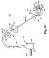
- FIG. 4is a cross-sectional view of the delivery cannula device of FIG. 2A upon final assembly
- FIG. 5is a side plan view of another embodiment of a delivery cannula device
- FIG. 6Ais a simplified plan view of an intraosseous curable material delivery system employed in a palliative bone procedure
- FIG. 6Billustrates a stage of a procedure performed by the system of FIG. 6A ;
- FIG. 6Cis a transverse, sectional view of a vertebral body in combination with a portion of the system of FIG. 6A , illustrating injection of curable material after the delivery cannula has been curved by application of heat thereto to reach a temperature corresponding to a desired curve;
- FIG. 6Dis a transverse, sectional view of a vertebral body illustrating possible vertebroplasty approach positions using embodiments disclosed herein;
- FIGS. 7A-7Care simplified anterior views of a vertebral body, illustrating use of one device embodiment
- FIGS. 8A and 8Bare simplified lateral views of a vertebral body, illustrating use of one device embodiment
- FIG. 9is a simplified lateral view of a vertebral body, illustrating use of one device embodiment
- FIG. 10is a simplified lateral view of a vertebral body, illustrating use of one device embodiment
- FIGS. 11A-11Care simplified anterior views of a vertebral body, illustrating use of one device embodiment.
- FIG. 12is a simplified anterior view of a sacrum, illustrating use of the one device embodiment.
- FIG. 1illustrates components of an intraosseous, curable material delivery system 20 .
- the system 20includes an outer guide cannula 22 and a delivery cannula device 26 (referenced generally). Details on the various components are provided below. In general terms, however, a portion of the delivery cannula device 26 is sized to be slidably disposed within the guide cannula 22 that otherwise serves to form and/or locate a desired delivery site within bone. After it is positioned through the guide cannula lumen, the delivery cannula device 26 may be employed to inject a curable, bone stabilizing material into the delivery site.
- the system 20can be used for a number of different procedures, including, for example, vertebroplasty and other bone augmentation procedures in which curable material is delivered to a site within bone, as well as to remove or aspirate material from a site within bone.
- the system 20and in particular the delivery cannula device 26 , is highly useful for delivering a curable material in the form of a bone cement material.
- curable materialwithin the context of the substance that can be delivered by the system/device of the invention described herein is intended to refer to materials (e.g., composites, polymers, and the like) that have a fluid or flowable state or phase and a hardened, solid or cured state or phase.
- Curable materialsinclude, but are not limited to injectable polymethylmethacrylate (PMMA) bone cement, which has a flowable state wherein it can be delivered (e.g., injected) by a cannula to a site and subsequently cures into hardened cement.
- PMMApolymethylmethacrylate
- the system 20further includes a source (not shown) of curable material fluidly coupled to the delivery cannula device 26 .
- the outer guide cannula 22generally enables access of the delivery cannula device 26 to a bone site of interest, and thus can assume a wide variety of forms.
- the guide cannula 22is sized to slidably receive a portion of the delivery cannula device 26 , terminating in an open, distal tip 28 .
- the distal tip 28can further be adapted to facilitate coring of bone tissue, such as when using the guide cannula 22 to form a delivery site within bone.
- an inner diameter surface of the guide cannula 22is highly smoothed to a matte or mirror finish (i.e., RMS range of about 0-18).
- the inner diameter surface of the guide cannula 22 or the outer diameter surface of the delivery cannula 36can be coated with, for example, polytetrafluoroethylene (PTFE) or another low-friction or lubricious material to promote a smooth desired interface between the guide cannula 22 and a portion of the delivery cannula device 26 otherwise slidably inserted within the guide cannula 22 during use.
- PTFEpolytetrafluoroethylene
- a PTFE sleeve between the guide cannula 22 and a portion of the delivery cannula device 26may also be used.
- the outer diameter surface of the delivery cannula 36can be polished to a highly smoothed to a matte or mirror finish (i.e., RMS range of about 0-18).
- the guide cannula 22can further be attached, at a proximal end thereof, to a handle 30 for enhancing a surgeon's ability to manipulate the system 20 .
- the handle 30can be eliminated.
- the delivery cannula device 26includes a memory metal material.
- the elongate tubular body 36which may be embodied as a vertebroplasty needle or other bone augmentation needle, may be constructed of—for example—Nitinol and/or another memory metal. Memory-metal materials are well-known in the art.
- the body 36may generally be formed as a polymeric tube with one or more lengthwise (linear, curved, spiral, etc.) memory metal supports.
- the memory metal supportsmay be disposed on one or more of an inner surface, an outer surface, and embedded in the wall of the polymeric tube (which may be, for example, made of PEEK or another suitable material with sufficient stiffness—as supported by the memory metal—to provide the structural and functional features described herein.
- a cannula body 36 including a memory metal materialmay be configured to have a generally straight-line body at a first temperature, such as—for example—a typical ambient temperature, which body generally defines a longitudinal axis.
- the memory metalmay provide both structural rigidity needed to operate in target tissue and the temperature-dependent curvature presently disclosed.
- the memory metal portion of the bodymay be configured to provide at least a first curvature of a distal deflectable length of the cannula body 36 when heated to a first elevated temperature, a second curvature at a second elevated temperature, and so on for a plurality of temperature-dependent curvature states where the deflectable portion is curved out of the longitudinal axis by a known amount.
- This configuration of the memory metalmay be provided by thermosetting of the memory metal during manufacture, applying technology known and used in the art of memory metal manufacture.
- the body 36is generally straight, and—with reference to the following table—
- the curvature of the Corresponding to a distal delivery cannula dashed-line curved end 82 relative to the orientation in FIG. 1 At about this temperature longitudinal axismay designated by (e.g., +/ ⁇ 4° C.) be about: reference number: 45° C. 30° 82w 55° C. 60° 82x 65° C. 90° 82y 75° C. 120° 82z These temperatures are examples only. Other curves corresponding to other temperatures may be included. Most preferably, the curvature desired may be assumed with a short application of heat to reach the desired temperature, where the heat and associated temperature are within relatively low-risk tolerances for a patient being treated. As another example, a temperature of about 60° C.
- ambient temperaturemay correspond to a straight cannula
- a temperature of about 65° C.may correspond to a curvature of about 55°
- a temperature of about 80° C.may correspond to a curvature of about 95°.
- two, three, or more pre-set curvesmay be used that correspond with selected temperatures (where the greater degrees of curvature away from the longitudinal axis generally correspond to higher temperatures). The curves may range from more than 1, but less than about 10 degrees to nearly 180 degrees, with a preferred range of about 20 degrees to about 135 degrees.
- a location within the bonethat is not readily accessible through a single-entry (e.g., unipedicular) approach using a straight needle or a delivery cannula available with a particular pre-set curve.
- Providing a plurality of delivery cannulas with different pre-set curvatures as part of a surgical kitpresents barriers of cost and convenience not present in the present system.
- the present system's cannula curvaturemay be adjusted “on the fly” by applying heat to the cannula sufficient to change the curvature.
- a multi-needle systemwould require swapping out and reloading a new delivery cannula and most likely making a new batch of curable bone cement material. With the present system, a different curvature may be realized without incurring the additional time, expense, and risk associated with device exchange and extended procedural requirements.
- the delivery cannula device 26is shown in greater detail in FIG. 2A , and generally includes a handle assembly 32 (referenced generally), a hub 34 , and a delivery cannula 36 .
- the hub port 34forms a fluid port and is fluidly connected to the delivery cannula 36 , with the handle assembly 32 retaining the combination hub 34 /delivery cannula 36 .
- the delivery cannula 36is sized to be coaxially, slidably received within the guide cannula 22 ( FIG. 1 ), and is adapted to deliver a curable material injected therein via the hub 34 .
- the handle assembly 32includes, in one embodiment, a handle 40 and a retainer 42 .
- the handle 40is adapted to receive the hub 34 , with the retainer 42 securing the hub 34 (and thus the delivery cannula 36 ) to the handle 40 .
- the handle 40in one embodiment, includes a first section 44 adapted for snap-fit assembly to a second section 46 , such as by complimentary annular protrusion(s) 48 and grooves 50 .
- the first section 44forms a central passage 52 extending inwardly from an exterior surface 54 thereof.
- the second section 46defines an internal aperture 56 that, upon final assembly of the handle 40 , is aligned with the central passage 52 .
- the aperture 56can assume a variety of forms sized to receive the hub 34 in a nested manner.
- the nested interface between the handle 40 and the hub 34is preferably adapted such that the hub 34 cannot rotate relative to the handle 40 upon final assembly (i.e., the hub 34 /handle 40 interface resists a torque imparted on either component such that rotational movement of the handle 40 results in an identical rotation of the hub 34 /delivery cannula 36 even when the delivery cannula 36 is inserted within a confined surgical site).
- the aperture 56 and the hub element 34may have corresponding non-symmetrical or non-circular shapes in transverse cross-section.
- the second section 46may include exterior threads 62 .
- the handle assembly 32can assume a wide variety of other forms and in some embodiments can be eliminated entirely.
- the hub 34may include a conventional fluid port design and defines a fluid passage 71 and an exterior thread 72 on a proximal end 74 thereof.
- the thread 72is a double start right hand Luer thread including a 5-millimeter lead, although other thread conformations and lead sizes are also acceptable.
- the hub 34is configured to be rotatably “locked” relative to the handle assembly 32 upon final assembly.
- a body of the hub 34forms a generally cylindrical surface 76 a portion of which is flattened in an area 78 , as shown in FIG. 2B .
- the size and shape of the flattened area 78corresponds with the aperture sidewall 58 ( FIG. 2A ) provided with the handle 40 ( FIG. 2A ).
- a removable cap 38may be provided, adapted to attach to the first section 44 of the handle assembly 32 and cover the fluid passage 71 of the hub 34 .
- the delivery cannula 36defines a proximal end 80 and a distal end 82 , and forms one or more side orifices 84 adjacent the distal end 80 and in fluid communication with an internal delivery cannula lumen 86 .
- the delivery cannula 36includes a deflectable distal segment 88 (referenced generally) defining a plurality of pre-set curves or bends 90 as herein described.
- the deflectable segment 88and in particular the bend(s) 90 , includes or extends from the distal end 82 , and has a shape memory attribute. As described above, and shown in FIG. 1 , the deflectable segment 88 may be directed into different curvatures.
- the proximal end 80is axially open to the lumen 86 .
- the distal end 82is axially closed to the lumen 86 , and the distal end 82 defines or includes a blunt tip 100 .
- the blunt tip 100defines a hemispherical surface, although other blunt (i.e., curved or curvilinear) shapes or contours are also acceptable.
- the side orifice(s) 84is formed adjacent the distal end 82 , extending through a thickness of a sidewall of the delivery cannula 36 .
- a single orifice 84is provided, and is located generally opposite a direction of the bend 90 .
- a direction of the bend 90serves to form the delivery cannula 36 to define an interior bend side 102 and an exterior bend side 104 .
- the side orifice 84is formed along, and is open relative to, the exterior bend side 104 .
- the side orifice(s) 84can assume a wide variety of shapes and sizes (relative to an exterior surface of the delivery cannula 36 ).
- the side orifice(s) 84can be oval, circular, curvilinear, etc.
- a chamfered region 106can be formed about the side orifice 84 to eliminate sharp edges along an exterior of the delivery catheter 36 as well as to promote consistent flow of curable material from the side orifice 84 (via the expanding orifice size effectuated by the chamfered region 106 ).
- an orifice length L and width Ware defined.
- the length Lmay be greater than 0.050 inch, preferably greater than 0.075 inch, and even more preferably greater than 0.100 inch.
- the side orifice 84may be characterized as being relatively large, especially as compared to conventional bone cement delivery needles that otherwise provide only an axial orifice or opening at the distal tip.
- the delivery cannula 36defines an inside diameter ID (i.e., a diameter of the lumen 86 ).
- the side orifice 84is fluidly connected to the lumen 86 and extends in a radial fashion. With these conventions in mind, in one embodiment, the length L of the side orifice 84 is greater the inside diameter ID of the delivery cannula 36 .
- At least one linear dimension of the side orifice 84is larger than any orifice dimension that could otherwise be achieved were an orifice to be formed at the distal end 82 (i.e., an axially extending orifice). That is to say, an orifice formed at and by the distal end 82 of the delivery cannula 82 (as is conventionally employed in the bone cement delivery needle art) is limited in size (i.e., diameter) by the inside diameter ID of the delivery cannula 36 .
- the side orifice 84 in accordance with principles of the present inventionis much larger, presenting a distinct advantage when attempting to pass a high viscosity liquid (curable material such as bone cement) therethrough.
- the delivery cannula 36defines a continuous length between its proximal end 80 and its distal end 82 , with its deflectable segment 88 including the bend 90 , extending along approximately 25% of the length from the distal end 82 (where the length of the delivery cannula 36 is the length of extension from the hub 34 upon final assembly).
- the deflectable segment 88and in particular the bend 90 , may extend along between 10%-50% of the length of the delivery cannula 36 as measured from the distal end 82 .
- FIG. 4shows an assembled view of the delivery cannula device 26 that was shown in exploded longitudinal section view of FIG. 2A .
- the deflectable segment 88can be formed to define the bend 90 at a pre-determined radius of curvature R, with the distal tip 100 offset from the longitudinal axis of the body 36 at a predetermined angle desired for targeting delivery to a particular site.
- a curable materiale.g., bone cement
- the delivery cannula 36is formed of a shape memory metal.
- the delivery cannula 36comprises NitinolTM, a known shape memory alloy of nickel (Ni) and titanium (Ti).
- the bend 90is formed in the delivery cannula 36 by deforming a straight fluid delivery cannula under extreme heat for a prescribed period of time, which pre-sets a curved shape in the delivery cannula 36 .
- the pre-set curve or bend 90is formed in an initially straight cannula by cold working the straight cannula and applying a mechanical stress. Cold working permanently locks a crystalline structure (for example, at least a partial martensitic crystalline structure) in a portion (i.e., the deflectable segment 88 ) of the cannula, while an unstressed portion remains in, for example, an austenitic structure.
- a crystalline structurefor example, at least a partial martensitic crystalline structure
- an unstressed portionremains in, for example, an austenitic structure.
- the deflectable segment 88is formed to be resilient and to assume the desired radius of curvature R under pre-determined conditions, as defined. In this manner, after the delivery cannula 36 , and in particular the deflectable segment 88 , is oriented a substantially straightened shape at a typical ambient temperature (as shown in FIG.
- the deflectable segment 88upon being heated, the deflectable segment 88 “remembers” the pre-set curved shape(s) and reversibly relaxes/returns to a first, second, or further curvature defining a bend 90 , as described in detail below.
- FIG. 1An additional feature of the delivery cannula 36 in accordance with one embodiment is shown in the plan view of FIG. 1 , which includes indicia 110 (referenced generally) adjacent the proximal end 80 .
- the indicia 110are indicative of a location of the distal end 82 relative to the distal tip 28 of the guide cannula 22 upon insertion of the delivery cannula 36 within the guide cannula 22 .
- the indicia 110may include first, second, and third depth markings 110 a , 110 b , 110 c corresponding to a set distance of extension from the distal end of the guide cannula.
- a longitudinal location of the first depth marking 110 a relative to the distal end 82may be commensurate with a length of the guide cannula 22 in combination with the handle 30 (where provided).
- the present inventionincludes a probe (not shown) in the form of a wire that can be inserted into the delivery cannula device 26 to remove blockages that may form within the delivery cannula 36 .
- the probehas a diameter that is smaller than the inner diameter of the delivery cannula 36 to allow material within the delivery cannula 36 to flow around the probe as the probe is inserted into the delivery cannula 36 .
- the probeis flexible enough to travel through the curvature of the delivery cannula 36 , but still rigid enough to remove blockages within the delivery cannula 36 .
- FIG. 5illustrates portions of a different embodiment delivery cannula device 120 .
- the delivery cannula device 120includes a delivery cannula 122 that extends a length between a proximal end 124 and a distal end 126 , and a hub 128 coupled to the proximal end 124 .
- the delivery cannula 122is similar to the delivery cannula 36 ( FIG.
- the delivery cannula 122includes a deflectable segment 132 forming a plurality of pre-set temperature-dependent curves along a segment 134 , similar to previous embodiments (only one of which is shown in FIG. 5 ).
- a distal-most side orifice 130 ais offset a distance D 1 from the distal end 116 .
- the distance D 1is, in one embodiment, in the range of 0.05-0.5 inch, preferably in the range of 0.1-0.25 inch.
- a longitudinal spacing between the remaining side orifices 130 proximal the distal-most side orifice 130 acan vary.
- the second side orifice 130 bdefines a smaller sized opening as compared to the distal-most side orifice 130 a
- the third side orifice 130 cis smaller than the second side orifice 130 b . This reduction in side orifice size proximal the distal end 126 promotes consistent distribution of curable material otherwise being forced through the delivery cannula 122 .
- the side orifices 130While three of the side orifices 130 are shown, other configurations are also acceptable. For example, multiple side orifices (i.e., two or more than three side orifices) can be formed longitudinally along the length of the delivery cannula 122 , and in addition, the side orifices 130 can include more than one longitudinally aligned series of side orifices. In an exemplary embodiment, the side orifices 130 that are visible in FIG. 5 are matched by another column of longitudinally aligned side orifices formed on an opposing side of the delivery cannula 122 (and therefore not visible in the view of FIG. 5 ). Aspects of the present invention provide for the side orifices 130 to define circular side orifices, non-circular side orifices, or a set of circular and non-circular side orifices.
- the pre-set curve 134 shownis curved away from a central longitudinal axis C of the delivery cannula 122 such that the curvature of the pre-set curve 134 is less than the radius of curvature R of the pre-set curve 90 ( FIG. 2A ) previously described, thus illustrating another embodiment in accordance with principles of the present invention.
- the side orifices 130are depicted as formed along the pre-set curve 134 , in another embodiment at least one of the side orifices 130 may be formed proximal the pre-set curve 134 .
- FIG. 6Aillustrates an intraosseous curable material delivery system 150 according to one embodiment of the present invention, employed to perform a vertebroplasty procedure.
- the system 150includes the outer guide cannula 22 , the delivery cannula device 26 , a curable material source 152 fluidly coupled to the delivery cannula device 26 , and a controller 154 coupled to at least the curable material source 152 .
- the curable material source 152includes, in one embodiment, a canister 160 containing a curable material as previously described, and tubing 164 extending from the canister 160 to the handle assembly 30 of the delivery cannula device 26 .
- the tubing 164terminates at a fitting 166 configured to removably attach to the hub 34 .
- the fitting 166is configured to fit within the passage 52 of the handle 40 and removably couple to the hub 34 .
- the fitting 166threads onto a Luer thread defined by the hub 34 .
- the fitting 166snap-fits over the hub 34 .
- a wide variety of other attachment configurationsare also available.
- the controller 154can assume any form known in the art and may be coupled to a curable material source 152 .
- the controller 154will control a mass flow and a mass flow rate (i.e., a fluid delivery rate) of curable material from the canister 160 to the delivery cannula device 26 , as well as a temperature of the delivery cannula (by providing heat energy calibrated and controlled to generate a specific desired temperature corresponding to a desired pre-set curvature).
- the heat energymay be provided by any number of means known in the art including—by way of illustrative example—resistance circuits, RF energy, injection through the cannula of heated water or other material, ultrasonic energy, or other means.
- the controller 154can include a variety of actuators (e.g., switch(es), foot pedal(s), etc.) affording a user the ability to remotely control liquid flow into the delivery cannula 36 and/or to control temperature (with the latter actuator(s) preferably including indicia corresponding to the temperature and/or curvature desired).
- actuatorse.g., switch(es), foot pedal(s), etc.
- manual controlcan be employed such that the controller 154 can be eliminated for use in dispensing curable material.
- the outer guide cannula 22is located at a desired delivery site within bone.
- the outer guide cannula 22is introduced into a vertebra 180 , preferably at a pedicle 182 .
- the vertebra 180includes a vertebral body 184 defining a vertebral wall 186 surrounding bodily material (e.g., cancellous bone, blood, marrow, and other soft tissue) 188 .
- the pedicle 182extends from the vertebral body 184 and surrounds a vertebral foramen 190 .
- the pedicle 182is attached posteriorly to the vertebral body 184 and together they comprise the vertebrae 180 and form the walls of the vertebral foramen 190 .
- the intraosseous system 150is suitable for accessing a variety of bone sites.
- a vertebra 180is illustrated, it is to be understood that other bone sites can be accessed by the system 150 (i.e., femur, long bones, ribs, sacrum, etc.).
- the outer guide cannula 22forms an access path to a delivery site 192 (or forms the delivery site 192 ) through the pedicle 182 into the bodily material 188 .
- the outer guide cannula 22has been driven through the pedicle 182 via a transpedicular approach.
- the transpedicular approachlocates the outer guide cannula 22 between the mammillary process and the accessory process of the pedicle 182 .
- the outer guide cannula 22provides access to the delivery site 192 at the open, distal tip 28 .
- the outer guide cannula 22can similarly perform a coring-like operation, forming an enlarged opening within bone.
- the distal tip 28 of the guide cannula 22is positioned close to the entrance point into the delivery site 192 .
- the smaller the projection of the distal tip 28 into the delivery site 192allows for greater access for the delivery cannula 36 to be positioned within the delivery site 192 and deliver curable material to desired locations within the delivery site 192 .
- the delivery cannula 36is slidably inserted/distally advanced within the outer guide cannula 22 .
- a stylet, drill, or other instrumentmay be used as known in the art to form a delivery site 192 (e.g., directed through the guide cannula 22 , used to form the site, then withdrawn before insertion of the delivery cannula).
- the distal end 82 of the delivery cannula 36is poised at the distal tip 28 of the outer guide cannula 22 .
- Approximate alignment of the first depth marking 110 a with the handle 30provides a user with visual confirmation (at a point outside of the patient) of the distal end 82 positioning relative to the outer guide cannula 22 distal tip 28 .
- the delivery cannula 36Prior to further distal movement, the delivery cannula 36 is entirely within the outer guide cannula 22 with the deflectable segment 88 ( FIG. 2A ) of the delivery cannula 36 in a substantially straightened shape that generally conforms to a shape of the outer guide cannula 22 .
- the delivery cannula device 26and in particular the delivery cannula 36 , is then distally advanced within the guide cannula 22 as shown in FIG. 6B .
- the delivery cannula 36is distally maneuvered such that at least a portion of the deflectable segment 88 extends beyond the open tip 28 of the guide cannula 22 and into the delivery site 192 .
- the deflectable segment 88may be actuated to deflect to a desired pre-set first, second, or other curvature upon exiting the guide catheter 22 , assuming the pre-set curvature of the bend 90 described above due to the shape memory characteristic being activated by application of heat energy to heat the needle to a corresponding temperature as described above.
- the usercan visually confirm a length of distal extension of the delivery catheter 36 from the guide catheter 22 via a longitudinal positioning of the indicia 110 b or 110 c (the indicia 110 c being visible in FIG. 6B ) relative to the handle 30 .
- the directional indicia 114indicate to a user (at a point outside of the patient) a spatial direction of the bend 90 that may be assumed within the delivery site 192 relative to a spatial position of the handle 40 .
- the blunt tip 100 of the distal end 82is hemispherically shaped (or other non-sharpened or blunt shape) and thus atraumatic relative to contacted tissue/bone. As such, the blunt tip 100 can contact and/or probe the vertebral wall 186 with a minimum of risk in puncturing or coring the vertebral body 184 . Thus, the blunt tip 100 offers an advantage over the conventional, sharp-edged bone cement delivery needles.
- the side orifice 84is offset from the distal end 82 and is, therefore, available to deliver curable material into, and remove bodily material from, the delivery site 192 .
- the side orifice 84can eject curable material radially from, and aspirate bodily material into, the delivery cannula 36 , even when the distal end 82 is pressed against a surface, such as an interior wall of the vertebral body 184 .
- the fluid source 152may then be operated (e.g., via the controller 154 ) to deliver a curable material (not shown) to the delivery cannula 36 via the hub 34 .
- Curable material entering the delivery cannula 36is forced through the lumen 86 ( FIG. 2A ) towards the side orifice 84 .
- the curable materialis then dispensed/injected from the delivery cannula 36 in a radial fashion from the side orifice(s) 84 and into the delivery site 192 in a cloud-like pattern 194 .
- the delivery site 192can be aspirated by replacing the curable material source 152 ( FIG. 6A ) with a vacuum source (not shown).
- curable materialis preloaded in the delivery cannula. That is, the curable material delivered to the delivery cannula 36 before introducing the delivery cannula 36 into the guide cannula 22 .
- an operatormay advance curable material beyond the side orifice(s) 84 the delivery cannula 36 in order to completely fill the delivery cannula 36 and then wipe the side orifice(s) 84 of excess curable material before insertion into the guide cannula 22 .
- the delivery cannula 36is thus preloaded with curable material before the delivery cannula 36 is connected with the guide cannula 22 .
- curable materialis immediately available to be delivered into the implantation site.
- This preloading stepadvantageously reduces the time required to deliver curable material into a patient because it can be done at substantially the same time the guide cannula 22 has being driven into the delivery site.
- FIG. 6Aillustrates a fracture 196 in the vertebral body wall 186 .
- Vertebroplastyis a common solution to such vertebral fractures, with the accepted repair technique entailing positioning the distal end 82 at or “facing” the fracture 196 to ensure that the curable material is dispensed in relatively close proximity thereto.
- this preferred approachresults in the curable material being injected directly toward the fracture 196 .
- the distal end 82is still “facing” or at least very near the fracture 196 , yet the injected curable material cloud 194 is not forced directly toward the fracture 196 .
- the curable material cloud 194indirectly reaches the fracture 196 with minimal retained propulsion force such that the curable material cloud 194 is unlikely to forcibly leak through the fracture 196 .
- the delivery site 192is, as a whole, still filled with the curable material cloud 194 to effectuate the desired repair.
- an entirety of the delivery site 192is accessible by the delivery cannula 36 .
- the system 150can effectuate a vertebroplasty procedure from a left posterior lateral approach, or to right or left anterior lateral approaches as shown in FIG. 6D (which shows two approaches, that could be used together, or in the alternative.
- a clinician operating the intraosseous system 150extends the deflectable end length of the cannula body 36 into the delivery site 192 otherwise defined within bone.
- a subsequent rotation of the delivery cannula 36rotates a spatial position of the side orifice 84 relative to the delivery site 192 , thus accessing multiple planes of the delivery site 192 with only one “stick” of the outer guide cannula 22 .
- FIGS. 7A-8Bgenerally illustrate ( FIGS. 7A-7C from an anterior perspective using three different curvatures; FIGS.
- a direction of the bend defined by the delivery cannula 36is not necessarily perpendicular to the plane of the page, such that the bend may not be fully evident in each view.
- a cliniciancreates voids 210 in soft body material 200 (e.g., cancellous bone, blood, marrow, and other soft tissue) within a bone delivery site by manipulating the curved end 90 of the delivery cannula 36 .
- the voids 210can then be filled with curable material. It has been observed that when voids are created, curable material delivered to the delivery site will generally flow into the voids 210 instead of the soft body material 200 .
- a cliniciancan create a void 210 at a relatively small desired area, and fill primarily just that area with curable material.
- voidscan be created through a combination of retracting the delivery cannula 36 within the outer guide cannula 22 and distally advancing the delivery cannula 36 relative to the outer guide cannula 22 , thus moving the curved end 90 in a reciprocating manner.
- the reciprocating actioncauses the curved end 90 to crush the soft body tissue and create a channel 212 within the soft body material.
- the curved end 90can create multiple channels 212 within the soft body tissue 200 .
- the curved end 90 of delivery cannula 36may be advanced distally only partially within the delivery site and then removed to create shorter channels 212 within the implantation site where desired. Actuating the different curvatures of the presently-disclosed delivery cannula may enable formation of a greater variety and/or number of voids than previously available via a single guide cannula without the disadvantages associated with exchanging out a delivery cannula for one with a different needed curvature, or having to settle for a different injection site than desired.
- the delivery cannula 36can be rotated or spun after the curved end 90 has been introduced into the implantation site.
- the rotating or spinning of the delivery cannula 36causes the curved end 90 to rotate through body tissue 200 to create a cone-shaped void 214 in the soft tissue 200 within the delivery site.
- one-shaped voids 214 of different sizes and locationsmay be created by inserting the curved end 90 into the implantation site by less than its full length and/or at different actuated curvatures and, thereafter, rotating the delivery cannula 36 .
- Voids 210 within the soft body tissue of various sizes and shapescan be created by using a combination of the above disclosed methods.
- a physicianmay introduce curable material within the implantation site as he or she is creating the voids within the implantation site.
- the voidsmay be created and filled at the same time.
- the delivery cannula of the present inventioncan be manipulated to deliver small deposits of curable material to specific desired areas within a cavity.
- curable materialcan be delivered in different planes to form curable material structures within the cavity to stabilize the endplates of a vertebral body 180 , as depicted in vertical transverse section in FIGS. 11A and 11B .
- the vertebral body 180will, in most treatment scenarios, have a degraded physiology not shown here, including one or more of vertical compression, structural disruption of one or more walls (e.g., endplates, lateral walls).
- curable material 232 a and 232 bis deposited in contact against the endplates 230 a and 230 b of the vertebral body so that the curable material substantially interfaces with the endplates 230 a and 230 b and provides structural support.
- the procedureleaves a region between the curable material deposits 232 a and 232 b that contains substantially no curable material.
- Curable materialcan thus be deposited in only a particular region or regions of the cavity. Physician desired localization of these deposits can be facilitated by the multi-curve device presently disclosed. For example, a physician may determine that a first deposit may best be achieved at a first curvature corresponding to a first temperature, a second deposit may best be achieved at a second curvature corresponding to a second temperature, etc. (for two or more desired curvatures and locations).
- the curable material deposits 232 a and 232 bcan be connected by placing curable material between the curable material deposits 232 a and 232 b to form a curable material stabilizing column 234 .
- curable material deposits 232 a and 232 bare first created to stabilize the endplates of the vertebral body.
- a stabilizing curable material column 234is then created between the curable material deposits 232 a and 232 b to connect the curable material deposits and form a curable material structure within the vertebral body.
- the vertebral body stiffnessmay be significantly improved thereby minimizing issues of the overall strength of the vertebral body. Some reduced vertebral height may even be recovered or at least not allowed significant further progress thereby.
- a physicianmay be able to exploit the multi-curve structure and function of the delivery cannula to help optimize location of the three deposits. For example, the first deposit 232 a may best be placed using a first curvature corresponding to a first temperature, the second deposit 232 b may best be placed using the same first curvature, and the intervening curable material column 234 may best be placed using a second curvature, reached by heating the needle to a second temperature.
- the delivery siteis the sacrum 220 , shown in horizontal transverse section.
- curable materialis delivered to the sacrum 220 to repair bone fragments or fractures in the sacrum.
- curable materialis delivered to multiple regions within the sacrum through a single access point.
- a guide cannula 22is inserted generally at the middle portion of the sacrum.
- a curvable needleis inserted into and advanced relative to the guide cannula 22 .
- the delivery cannula 36is preferably oriented so the curvable end 90 enters proximal to a first region 221 of the sacrum 220 after being heated to a first temperature corresponding to a first curvature shown in solid line (as “A”). Curable material is then delivered to the first region 221 of the sacrum 220 . After curable material is delivered to the first region 221 , the physician can then partially or fully retract the curved end 90 within the guide cannula and then re-orient the delivery cannula 36 and curved end 90 . As the delivery cannula 36 is again advanced relative to the guide cannula 22 , the curved end 90 enters proximal to a second region 222 within the sacrum 220 .
- Curable materialis then delivered to the second region 222 of the sacrum 220 using the same curvature (shown in dashed-line as “B”).
- the processcan be repeated for other additional regions, such as—for example—retracting the delivery cannula 36 just into the delivery cannula, heating it to a second temperature corresponding to a second curvature and re-introducing it (into dashed-line position “C”).
- the retracting/heating methodmay be used in other embodiments as well (e.g., rather than increasing heat to change curvature while the cannula 36 is extended within the bone).
- the implantation site described aboveis the sacrum, fractures in other bones can be repaired by delivering curable material to multiple regions through the same access point using the above described methods
Landscapes
- Health & Medical Sciences (AREA)
- Life Sciences & Earth Sciences (AREA)
- Surgery (AREA)
- Orthopedic Medicine & Surgery (AREA)
- Medical Informatics (AREA)
- General Health & Medical Sciences (AREA)
- Biomedical Technology (AREA)
- Heart & Thoracic Surgery (AREA)
- Nuclear Medicine, Radiotherapy & Molecular Imaging (AREA)
- Molecular Biology (AREA)
- Animal Behavior & Ethology (AREA)
- Engineering & Computer Science (AREA)
- Public Health (AREA)
- Veterinary Medicine (AREA)
- Surgical Instruments (AREA)
- Pathology (AREA)
- Dentistry (AREA)
- Oral & Maxillofacial Surgery (AREA)
Abstract
Description
| The curvature of the | Corresponding to a | |
| distal delivery cannula | dashed-line | |
| end | ||
| 82 relative to the | orientation in FIG. 1 | |
| At about this temperature | longitudinal axis may | designated by |
| (e.g., +/−4° C.) | be about: | reference number: |
| 45° C. | 30° | 82w |
| 55° C. | 60° | 82x |
| 65° C. | 90° | 82y |
| 75° C. | 120° | 82z |
These temperatures are examples only. Other curves corresponding to other temperatures may be included. Most preferably, the curvature desired may be assumed with a short application of heat to reach the desired temperature, where the heat and associated temperature are within relatively low-risk tolerances for a patient being treated. As another example, a temperature of about 60° C. may correspond to a curvature of about 45°, a temperature of about 70° C. may correspond to a curvature of about 90°, and a temperature of about 80° C. may correspond to a curvature of about 135°. In another embodiment, ambient temperature may correspond to a straight cannula, a temperature of about 65° C. may correspond to a curvature of about 55°, and a temperature of about 80° C. may correspond to a curvature of about 95°. In other words, subject to the physical limitations of the memory metal material, two, three, or more pre-set curves may be used that correspond with selected temperatures (where the greater degrees of curvature away from the longitudinal axis generally correspond to higher temperatures). The curves may range from more than 1, but less than about 10 degrees to nearly 180 degrees, with a preferred range of about 20 degrees to about 135 degrees.
Claims (20)
Priority Applications (10)
| Application Number | Priority Date | Filing Date | Title |
|---|---|---|---|
| US13/483,899US8690884B2 (en) | 2005-11-18 | 2012-05-30 | Multistate-curvature device and method for delivering a curable material into bone |
| US14/223,064US9358059B2 (en) | 2005-11-18 | 2014-03-24 | Device and method for delivering a curable material into bone |
| US14/528,384US9168078B2 (en) | 2009-11-10 | 2014-10-30 | Apparatus and method for stylet-guided vertebral augmentation |
| US14/873,947US9526551B2 (en) | 2009-11-10 | 2015-10-02 | Apparatus and method for stylet-guided vertebral augmentation |
| US15/076,221US9795429B2 (en) | 2005-11-18 | 2016-03-21 | Device and method for removing bodily material |
| US15/348,541US9907595B2 (en) | 2009-11-10 | 2016-11-10 | Systems and methods for vertebral or other bone structure height restoration and stabilization |
| US15/647,774US10022173B2 (en) | 2009-11-10 | 2017-07-12 | Systems and methods for vertebral or other bone structure height restoration and stabilization |
| US15/699,084US10314633B2 (en) | 2005-11-18 | 2017-09-08 | Shape memory device with temperature-dependent deflectable segment and methods of positioning a shape memory device within a bone structure |
| US16/004,997US10905487B2 (en) | 2009-11-10 | 2018-06-11 | Systems and methods for vertebral or other bone structure height restoration and stabilization |
| US17/142,301US11666366B2 (en) | 2009-11-10 | 2021-01-06 | Systems and methods for vertebral or other bone structure height restoration and stabilization |
Applications Claiming Priority (4)
| Application Number | Priority Date | Filing Date | Title |
|---|---|---|---|
| US11/282,102US7713273B2 (en) | 2005-11-18 | 2005-11-18 | Device, system and method for delivering a curable material into bone |
| US11/704,139US7799035B2 (en) | 2005-11-18 | 2007-02-08 | Device, system and method for delivering a curable material into bone |
| US12/633,358US8529576B2 (en) | 2005-11-18 | 2009-12-08 | Device, system and method for delivering a curable material into bone |
| US13/483,899US8690884B2 (en) | 2005-11-18 | 2012-05-30 | Multistate-curvature device and method for delivering a curable material into bone |
Related Parent Applications (1)
| Application Number | Title | Priority Date | Filing Date |
|---|---|---|---|
| US12/633,358Continuation-In-PartUS8529576B2 (en) | 2005-11-18 | 2009-12-08 | Device, system and method for delivering a curable material into bone |
Related Child Applications (2)
| Application Number | Title | Priority Date | Filing Date |
|---|---|---|---|
| US14/223,064ContinuationUS9358059B2 (en) | 2005-11-18 | 2014-03-24 | Device and method for delivering a curable material into bone |
| US14/223,064Continuation-In-PartUS9358059B2 (en) | 2005-11-18 | 2014-03-24 | Device and method for delivering a curable material into bone |
Publications (2)
| Publication Number | Publication Date |
|---|---|
| US20120239050A1 US20120239050A1 (en) | 2012-09-20 |
| US8690884B2true US8690884B2 (en) | 2014-04-08 |
Family
ID=46829057
Family Applications (4)
| Application Number | Title | Priority Date | Filing Date |
|---|---|---|---|
| US13/483,899Active2025-12-31US8690884B2 (en) | 2005-11-18 | 2012-05-30 | Multistate-curvature device and method for delivering a curable material into bone |
| US14/223,064ActiveUS9358059B2 (en) | 2005-11-18 | 2014-03-24 | Device and method for delivering a curable material into bone |
| US15/076,221ActiveUS9795429B2 (en) | 2005-11-18 | 2016-03-21 | Device and method for removing bodily material |
| US15/699,084ActiveUS10314633B2 (en) | 2005-11-18 | 2017-09-08 | Shape memory device with temperature-dependent deflectable segment and methods of positioning a shape memory device within a bone structure |
Family Applications After (3)
| Application Number | Title | Priority Date | Filing Date |
|---|---|---|---|
| US14/223,064ActiveUS9358059B2 (en) | 2005-11-18 | 2014-03-24 | Device and method for delivering a curable material into bone |
| US15/076,221ActiveUS9795429B2 (en) | 2005-11-18 | 2016-03-21 | Device and method for removing bodily material |
| US15/699,084ActiveUS10314633B2 (en) | 2005-11-18 | 2017-09-08 | Shape memory device with temperature-dependent deflectable segment and methods of positioning a shape memory device within a bone structure |
Country Status (1)
| Country | Link |
|---|---|
| US (4) | US8690884B2 (en) |
Cited By (20)
| Publication number | Priority date | Publication date | Assignee | Title |
|---|---|---|---|---|
| US20140257302A1 (en)* | 2013-03-11 | 2014-09-11 | Eca Medical Instruments | Co-axial hot swappable system for minimally invasive medical procedures |
| US20140303632A1 (en)* | 2005-11-18 | 2014-10-09 | Carefusion 2200, Inc. | Device and method for delivering a curable material into bone |
| US9168078B2 (en) | 2009-11-10 | 2015-10-27 | Carefusion 2200, Inc. | Apparatus and method for stylet-guided vertebral augmentation |
| US20160228131A1 (en)* | 2013-10-15 | 2016-08-11 | Stryker Corporation | Device for creating a void space in a living tissue, the device including a handle with a control knob that can be set regardless of the orientation of the handle |
| US9724107B2 (en) | 2008-09-26 | 2017-08-08 | Relievant Medsystems, Inc. | Nerve modulation systems |
| US9724151B2 (en) | 2013-08-08 | 2017-08-08 | Relievant Medsystems, Inc. | Modulating nerves within bone using bone fasteners |
| US9775627B2 (en) | 2012-11-05 | 2017-10-03 | Relievant Medsystems, Inc. | Systems and methods for creating curved paths through bone and modulating nerves within the bone |
| US10111704B2 (en) | 2002-09-30 | 2018-10-30 | Relievant Medsystems, Inc. | Intraosseous nerve treatment |
| US10265099B2 (en) | 2008-09-26 | 2019-04-23 | Relievant Medsystems, Inc. | Systems for accessing nerves within bone |
| US10390877B2 (en) | 2011-12-30 | 2019-08-27 | Relievant Medsystems, Inc. | Systems and methods for treating back pain |
| US10463423B2 (en) | 2003-03-28 | 2019-11-05 | Relievant Medsystems, Inc. | Thermal denervation devices and methods |
| US10588691B2 (en) | 2012-09-12 | 2020-03-17 | Relievant Medsystems, Inc. | Radiofrequency ablation of tissue within a vertebral body |
| USRE48460E1 (en) | 2002-09-30 | 2021-03-09 | Relievant Medsystems, Inc. | Method of treating an intraosseous nerve |
| US11007010B2 (en) | 2019-09-12 | 2021-05-18 | Relevant Medsysterns, Inc. | Curved bone access systems |
| US11224910B2 (en)* | 2017-03-03 | 2022-01-18 | Cook Medical Technologies Llc | Method of forming a bend of a predetermined bend angle in a shape memory alloy wire and method of making a self-expanding stent |
| US11628009B2 (en) | 2014-12-17 | 2023-04-18 | Biosense Webster (Israel) Ltd. | EP catheter with trained support member, and related methods |
| US11849986B2 (en) | 2019-04-24 | 2023-12-26 | Stryker Corporation | Systems and methods for off-axis augmentation of a vertebral body |
| US12039731B2 (en) | 2020-12-22 | 2024-07-16 | Relievant Medsystems, Inc. | Prediction of candidates for spinal neuromodulation |
| US12082876B1 (en) | 2020-09-28 | 2024-09-10 | Relievant Medsystems, Inc. | Introducer drill |
| US12433668B1 (en) | 2021-11-08 | 2025-10-07 | Relievant Medsystems, Inc. | Impedance stoppage mitigation during radiofrequency tissue ablation procedures |
Families Citing this family (21)
| Publication number | Priority date | Publication date | Assignee | Title |
|---|---|---|---|---|
| US20150359586A1 (en)* | 2000-02-03 | 2015-12-17 | Michael Heggeness | Device and method for alleviation of pain |
| US8808284B2 (en) | 2008-09-26 | 2014-08-19 | Relievant Medsystems, Inc. | Systems for navigating an instrument through bone |
| US8613744B2 (en) | 2002-09-30 | 2013-12-24 | Relievant Medsystems, Inc. | Systems and methods for navigating an instrument through bone |
| US8366773B2 (en) | 2005-08-16 | 2013-02-05 | Benvenue Medical, Inc. | Apparatus and method for treating bone |
| US8814873B2 (en) | 2011-06-24 | 2014-08-26 | Benvenue Medical, Inc. | Devices and methods for treating bone tissue |
| ITRM20110479A1 (en)* | 2011-09-09 | 2013-03-10 | O P A Medical S R L | GROUP FOR CIFOPLASTIC INTERVENTIONS |
| US9439693B2 (en)* | 2013-02-01 | 2016-09-13 | DePuy Synthes Products, Inc. | Steerable needle assembly for use in vertebral body augmentation |
| US10085783B2 (en) | 2013-03-14 | 2018-10-02 | Izi Medical Products, Llc | Devices and methods for treating bone tissue |
| US10252009B2 (en)* | 2013-04-08 | 2019-04-09 | Syracuse University | Heat-curling polymeric needle for safe disposal |
| US9504507B2 (en)* | 2013-07-05 | 2016-11-29 | Tecres S.P.A. | Injector device for introducing biocompatible material into deep anatomical areas |
| US9968373B1 (en) | 2014-02-21 | 2018-05-15 | Surgentec, Llc | Handles for needle assemblies |
| GB201405244D0 (en)* | 2014-03-24 | 2014-05-07 | T & T Devices Ltd | A nasal bridle insertion device |
| US10881428B2 (en)* | 2015-04-22 | 2021-01-05 | Medtronic, Inc. | Shaped lead introducer for epidural space |
| US9681889B1 (en)* | 2015-06-09 | 2017-06-20 | Surgentec, Llc | Depth controlled needle assembly |
| CN106361416B (en)* | 2016-09-26 | 2018-10-19 | 张广柱 | The minimally invasive micro multiple target point injecting systems of intracerebral for stereotaxis navigation equipment |
| KR102156112B1 (en)* | 2018-07-25 | 2020-09-15 | 한국과학기술연구원 | Apparatus for minimally invasive surgery |
| WO2020194051A2 (en)* | 2019-03-27 | 2020-10-01 | 3Nt Medical Ltd. | Handle for paranasal sinus access device |
| CN110301950B (en)* | 2019-07-19 | 2024-03-15 | 刘奇为 | Automatic suturing mechanism for minimally invasive surgery and endoscope |
| EP4162887A4 (en)* | 2020-06-09 | 2023-11-15 | Medicaretec Co., Ltd. | TUBE ELEMENT HAVING EXCELLENT LOCAL BENDING ABILITY, AND METHOD FOR MANUFACTURING IT |
| JP7586520B2 (en)* | 2020-06-09 | 2024-11-19 | メディケアテック カンパニー リミテッド | Tube member having locally excellent foldability and manufacturing method thereof |
| US20230404561A1 (en)* | 2022-06-16 | 2023-12-21 | Vertos Medical, Inc. | Integrated instrument assembly |
Citations (61)
| Publication number | Priority date | Publication date | Assignee | Title |
|---|---|---|---|---|
| US4265231A (en) | 1979-04-30 | 1981-05-05 | Scheller Jr Arnold D | Curved drill attachment for bone drilling uses |
| US4518383A (en)* | 1982-08-06 | 1985-05-21 | Evans John M | Instrument and method for epidural and spinal anaesthesia |
| US5295980A (en) | 1989-10-30 | 1994-03-22 | Ersek Robert A | Multi-use cannula system |
| US5609629A (en) | 1995-06-07 | 1997-03-11 | Med Institute, Inc. | Coated implantable medical device |
| US5732698A (en) | 1994-01-28 | 1998-03-31 | Ep Technologies, Inc. | Systems for examining the electrical characteristics of cardiac tissue while minimizing contact with blood within the heart |
| US5843103A (en) | 1997-03-06 | 1998-12-01 | Scimed Life Systems, Inc. | Shaped wire rotational atherectomy device |
| WO1998056301A1 (en) | 1997-06-09 | 1998-12-17 | Kyphon Inc. | Systems for treating fractured or diseased bone using expandable bodies |
| US5851209A (en) | 1996-01-16 | 1998-12-22 | Hospital For Joint Diseases | Bone cerclage tool |
| US5879353A (en) | 1995-01-17 | 1999-03-09 | Gore Enterprise Holdings, Inc. | Guided bone rasp |
| US5891147A (en) | 1996-06-25 | 1999-04-06 | Sdgi Holdings, Inc. | Minimally invasive spinal surgical methods & instruments |
| US5928239A (en) | 1998-03-16 | 1999-07-27 | University Of Washington | Percutaneous surgical cavitation device and method |
| US5972015A (en) | 1997-08-15 | 1999-10-26 | Kyphon Inc. | Expandable, asymetric structures for deployment in interior body regions |
| US6048346A (en) | 1997-08-13 | 2000-04-11 | Kyphon Inc. | Systems and methods for injecting flowable materials into bones |
| US6066154A (en) | 1994-01-26 | 2000-05-23 | Kyphon Inc. | Inflatable device for use in surgical protocol relating to fixation of bone |
| US6241734B1 (en) | 1998-08-14 | 2001-06-05 | Kyphon, Inc. | Systems and methods for placing materials into bone |
| US6248110B1 (en) | 1994-01-26 | 2001-06-19 | Kyphon, Inc. | Systems and methods for treating fractured or diseased bone using expandable bodies |
| US6296639B1 (en) | 1999-02-12 | 2001-10-02 | Novacept | Apparatuses and methods for interstitial tissue removal |
| US6328744B1 (en) | 1999-06-04 | 2001-12-11 | American Medical Systems, Inc. | Bone suturing device |
| US6358251B1 (en) | 2000-03-21 | 2002-03-19 | University Of Washington | Method and apparatus for forming a cavity in soft tissue or bone |
| US6383190B1 (en) | 1998-04-01 | 2002-05-07 | Parallax Medical, Inc. | High pressure applicator |
| US6383188B2 (en) | 2000-02-15 | 2002-05-07 | The Spineology Group Llc | Expandable reamer |
| US20020099384A1 (en) | 1998-08-14 | 2002-07-25 | Kyphon Inc. | Systems and methods for treating vertebral bodies |
| US6425887B1 (en) | 1998-12-09 | 2002-07-30 | Cook Incorporated | Multi-directional needle medical device |
| US6440138B1 (en) | 1998-04-06 | 2002-08-27 | Kyphon Inc. | Structures and methods for creating cavities in interior body regions |
| US20020120240A1 (en) | 2001-02-20 | 2002-08-29 | Bagga Charanpreet S. | System and kit for delivery of restorative materials |
| US20020156483A1 (en) | 2001-02-15 | 2002-10-24 | Voellmicke John C. | Vertebroplasty injection device and bone cement therefor |
| US6494868B2 (en) | 2000-04-27 | 2002-12-17 | Roger E. Amar | Set of cannulae for tissue injections in the human face |
| US20030036762A1 (en) | 2001-08-20 | 2003-02-20 | Kerr Sean H. | Threaded syringe for delivery of a bone substitute material |
| US20030078589A1 (en) | 1998-04-01 | 2003-04-24 | Preissman Howard E. | High pressure applicator |
| US6575978B2 (en) | 2001-04-05 | 2003-06-10 | Spineology, Inc. | Circumferential resecting reamer tool |
| US6645213B2 (en)* | 1997-08-13 | 2003-11-11 | Kyphon Inc. | Systems and methods for injecting flowable materials into bones |
| US6676664B1 (en) | 1999-08-05 | 2004-01-13 | Grupo Grifols, S.A. | Device for metering hardenable mass for vertebroplastia and other similar bone treatments |
| US6679886B2 (en) | 2000-09-01 | 2004-01-20 | Synthes (Usa) | Tools and methods for creating cavities in bone |
| US20040068264A1 (en) | 2002-10-03 | 2004-04-08 | Treace John T. | Bendable needle for delivering bone graft material and method of use |
| US20040068267A1 (en) | 2000-06-27 | 2004-04-08 | Fraser Harvie | Surgical procedures and instruments |
| US6740090B1 (en) | 2000-02-16 | 2004-05-25 | Trans1 Inc. | Methods and apparatus for forming shaped axial bores through spinal vertebrae |
| US6746451B2 (en) | 2001-06-01 | 2004-06-08 | Lance M. Middleton | Tissue cavitation device and method |
| US20040162559A1 (en) | 2003-02-14 | 2004-08-19 | Arramon Yves P. | Bone access system |
| US6783515B1 (en) | 1999-09-30 | 2004-08-31 | Arthrocare Corporation | High pressure delivery system |
| EP1459691A1 (en) | 1996-10-23 | 2004-09-22 | Oratec Interventions, Inc. | Method and apparatus for treating intervertebral discs |
| US6814734B2 (en) | 2001-06-18 | 2004-11-09 | Sdgi Holdings, Inc, | Surgical instrumentation and method for forming a passage in bone having an enlarged cross-sectional portion |
| US20050038432A1 (en) | 2003-04-25 | 2005-02-17 | Shaolian Samuel M. | Articulating spinal fixation rod and system |
| US20050070913A1 (en) | 2003-09-29 | 2005-03-31 | Milbocker Michael T. | Devices and methods for spine repair |
| US6921403B2 (en) | 2000-02-16 | 2005-07-26 | Trans1 Inc. | Method and apparatus for spinal distraction and fusion |
| US6923813B2 (en) | 2003-09-03 | 2005-08-02 | Kyphon Inc. | Devices for creating voids in interior body regions and related methods |
| US20060009779A1 (en) | 2004-06-29 | 2006-01-12 | Keith Collins | Devices for injecting a curable biomaterial into a intervertebral space |
| US7004945B2 (en) | 2001-11-01 | 2006-02-28 | Spinewave, Inc. | Devices and methods for the restoration of a spinal disc |
| US20060064101A1 (en) | 2004-02-12 | 2006-03-23 | Arthrocare Corporation | Bone access system |
| US7025771B2 (en) | 2000-06-30 | 2006-04-11 | Spineology, Inc. | Tool to direct bone replacement material |
| US20060116643A1 (en) | 2000-06-08 | 2006-06-01 | Dixon Christopher G | High pressure injection syringe |
| US7087058B2 (en) | 2000-02-16 | 2006-08-08 | Trans1, Inc. | Method and apparatus for providing posterior or anterior trans-sacral access to spinal vertebrae |
| US7087040B2 (en) | 2001-02-28 | 2006-08-08 | Rex Medical, L.P. | Apparatus for delivering ablation fluid to treat lesions |
| US20060195094A1 (en) | 2005-02-15 | 2006-08-31 | Mcgraw J K | Percutaneous spinal stabilization device and method |
| US20060217736A1 (en) | 2005-03-24 | 2006-09-28 | Gc Corporation | Bone cement injecting and filling method and leakage prevention bag for injecting and filling bone cement |
| US7114501B2 (en) | 2000-08-14 | 2006-10-03 | Spine Wave, Inc. | Transverse cavity device and method |
| US20060241624A1 (en) | 2005-04-13 | 2006-10-26 | Padl Inc. | Bone fixation device for surgical operation, cutting device and band head for the same |
| US20060264967A1 (en) | 2003-03-14 | 2006-11-23 | Ferreyro Roque H | Hydraulic device for the injection of bone cement in percutaneous vertebroplasty |
| US7682378B2 (en)* | 2004-11-10 | 2010-03-23 | Dfine, Inc. | Bone treatment systems and methods for introducing an abrading structure to abrade bone |
| US7713273B2 (en) | 2005-11-18 | 2010-05-11 | Carefusion 2200, Inc. | Device, system and method for delivering a curable material into bone |
| US20110245926A1 (en) | 2010-03-31 | 2011-10-06 | Kitchen Michael S | Intervertebral spacer and methods of use |
| US8128633B2 (en) | 2005-11-18 | 2012-03-06 | Carefusion 2200, Inc. | Device, system, and method for forming a cavity in and delivering a curable material into bone |
Family Cites Families (18)
| Publication number | Priority date | Publication date | Assignee | Title |
|---|---|---|---|---|
| US5370675A (en) | 1992-08-12 | 1994-12-06 | Vidamed, Inc. | Medical probe device and method |
| US4969888A (en) | 1989-02-09 | 1990-11-13 | Arie Scholten | Surgical protocol for fixation of osteoporotic bone using inflatable device |
| DE3922406C1 (en) | 1989-07-07 | 1990-10-11 | B. Braun Melsungen Ag, 3508 Melsungen, De | |
| US5512051A (en) | 1993-02-16 | 1996-04-30 | Boston Scientific Corporation | Slip-layered catheter balloon |
| US6019776A (en) | 1997-10-14 | 2000-02-01 | Parallax Medical, Inc. | Precision depth guided instruments for use in vertebroplasty |
| US6033411A (en) | 1997-10-14 | 2000-03-07 | Parallax Medical Inc. | Precision depth guided instruments for use in vertebroplasty |
| US6569179B2 (en) | 1998-11-10 | 2003-05-27 | Scimed Life Systems, Inc. | Bioactive three loop coil |
| CN101543422B (en) | 2000-04-07 | 2012-07-04 | 科丰有限公司 | System for determining the expansion direction of an expandable structure within a bone |
| US8690884B2 (en)* | 2005-11-18 | 2014-04-08 | Carefusion 2200, Inc. | Multistate-curvature device and method for delivering a curable material into bone |
| US7922690B2 (en) | 2006-02-22 | 2011-04-12 | Michael Plishka | Curable material delivery device |
| CA2737374C (en) | 2008-09-26 | 2017-03-28 | Relievant Medsystems, Inc. | Systems and methods for navigating an instrument through bone |
| EP2467099B1 (en) | 2009-08-19 | 2019-05-15 | Synthes GmbH | Apparatus for augmenting bone |
| TW201113886A (en) | 2009-10-09 | 2011-04-16 | Silicon Motion Inc | Method for enhancing performance of accessing a flash memory, and associated memory device and controller thereof |
| US8226657B2 (en) | 2009-11-10 | 2012-07-24 | Carefusion 207, Inc. | Systems and methods for vertebral or other bone structure height restoration and stabilization |
| US9095393B2 (en) | 2012-05-30 | 2015-08-04 | Carefusion 2200, Inc. | Method for balloon-aided vertebral augmentation |
| US8894658B2 (en) | 2009-11-10 | 2014-11-25 | Carefusion 2200, Inc. | Apparatus and method for stylet-guided vertebral augmentation |
| US20110112507A1 (en) | 2009-11-10 | 2011-05-12 | Carefusion 207, Inc. | Curable material delivery systems and methods |
| US9526538B2 (en) | 2009-12-07 | 2016-12-27 | Globus Medical, Inc. | Methods and apparatus for treating vertebral fractures |
- 2012
- 2012-05-30USUS13/483,899patent/US8690884B2/enactiveActive
- 2014
- 2014-03-24USUS14/223,064patent/US9358059B2/enactiveActive
- 2016
- 2016-03-21USUS15/076,221patent/US9795429B2/enactiveActive
- 2017
- 2017-09-08USUS15/699,084patent/US10314633B2/enactiveActive
Patent Citations (72)
| Publication number | Priority date | Publication date | Assignee | Title |
|---|---|---|---|---|
| US4265231A (en) | 1979-04-30 | 1981-05-05 | Scheller Jr Arnold D | Curved drill attachment for bone drilling uses |
| US4518383A (en)* | 1982-08-06 | 1985-05-21 | Evans John M | Instrument and method for epidural and spinal anaesthesia |
| US5295980A (en) | 1989-10-30 | 1994-03-22 | Ersek Robert A | Multi-use cannula system |
| US6066154A (en) | 1994-01-26 | 2000-05-23 | Kyphon Inc. | Inflatable device for use in surgical protocol relating to fixation of bone |
| US6248110B1 (en) | 1994-01-26 | 2001-06-19 | Kyphon, Inc. | Systems and methods for treating fractured or diseased bone using expandable bodies |
| US5732698A (en) | 1994-01-28 | 1998-03-31 | Ep Technologies, Inc. | Systems for examining the electrical characteristics of cardiac tissue while minimizing contact with blood within the heart |
| US5879353A (en) | 1995-01-17 | 1999-03-09 | Gore Enterprise Holdings, Inc. | Guided bone rasp |
| US5609629A (en) | 1995-06-07 | 1997-03-11 | Med Institute, Inc. | Coated implantable medical device |
| US5851209A (en) | 1996-01-16 | 1998-12-22 | Hospital For Joint Diseases | Bone cerclage tool |
| US5891147A (en) | 1996-06-25 | 1999-04-06 | Sdgi Holdings, Inc. | Minimally invasive spinal surgical methods & instruments |
| EP1459691A1 (en) | 1996-10-23 | 2004-09-22 | Oratec Interventions, Inc. | Method and apparatus for treating intervertebral discs |
| US5843103A (en) | 1997-03-06 | 1998-12-01 | Scimed Life Systems, Inc. | Shaped wire rotational atherectomy device |
| WO1998056301A1 (en) | 1997-06-09 | 1998-12-17 | Kyphon Inc. | Systems for treating fractured or diseased bone using expandable bodies |
| US6048346A (en) | 1997-08-13 | 2000-04-11 | Kyphon Inc. | Systems and methods for injecting flowable materials into bones |
| US6645213B2 (en)* | 1997-08-13 | 2003-11-11 | Kyphon Inc. | Systems and methods for injecting flowable materials into bones |
| US5972015A (en) | 1997-08-15 | 1999-10-26 | Kyphon Inc. | Expandable, asymetric structures for deployment in interior body regions |
| US5928239A (en) | 1998-03-16 | 1999-07-27 | University Of Washington | Percutaneous surgical cavitation device and method |
| US20040215202A1 (en) | 1998-04-01 | 2004-10-28 | Preissman Howard E. | High pressure applicator |
| US20030078589A1 (en) | 1998-04-01 | 2003-04-24 | Preissman Howard E. | High pressure applicator |
| US6383190B1 (en) | 1998-04-01 | 2002-05-07 | Parallax Medical, Inc. | High pressure applicator |
| US6863672B2 (en) | 1998-04-06 | 2005-03-08 | Kyphon Inc. | Structures and methods for creating cavities in interior body regions |
| US6440138B1 (en) | 1998-04-06 | 2002-08-27 | Kyphon Inc. | Structures and methods for creating cavities in interior body regions |
| US6241734B1 (en) | 1998-08-14 | 2001-06-05 | Kyphon, Inc. | Systems and methods for placing materials into bone |
| US20020099384A1 (en) | 1998-08-14 | 2002-07-25 | Kyphon Inc. | Systems and methods for treating vertebral bodies |
| US6641587B2 (en) | 1998-08-14 | 2003-11-04 | Kyphon Inc. | Systems and methods for treating vertebral bodies |
| US6592559B1 (en)* | 1998-12-09 | 2003-07-15 | Cook Incorporated | Hollow, curved, superlastic medical needle |
| US6425887B1 (en) | 1998-12-09 | 2002-07-30 | Cook Incorporated | Multi-directional needle medical device |
| US6296639B1 (en) | 1999-02-12 | 2001-10-02 | Novacept | Apparatuses and methods for interstitial tissue removal |
| US6843796B2 (en) | 1999-06-04 | 2005-01-18 | Ams Research Corporation | Bone suturing device |
| US6328744B1 (en) | 1999-06-04 | 2001-12-11 | American Medical Systems, Inc. | Bone suturing device |
| US6676664B1 (en) | 1999-08-05 | 2004-01-13 | Grupo Grifols, S.A. | Device for metering hardenable mass for vertebroplastia and other similar bone treatments |
| US7048743B2 (en) | 1999-09-30 | 2006-05-23 | Arthrocare Corporation | Methods for delivering tissue implant material with a high pressure applicator |
| US6783515B1 (en) | 1999-09-30 | 2004-08-31 | Arthrocare Corporation | High pressure delivery system |
| US6383188B2 (en) | 2000-02-15 | 2002-05-07 | The Spineology Group Llc | Expandable reamer |
| US6921403B2 (en) | 2000-02-16 | 2005-07-26 | Trans1 Inc. | Method and apparatus for spinal distraction and fusion |
| US6790210B1 (en) | 2000-02-16 | 2004-09-14 | Trans1, Inc. | Methods and apparatus for forming curved axial bores through spinal vertebrae |
| US7087058B2 (en) | 2000-02-16 | 2006-08-08 | Trans1, Inc. | Method and apparatus for providing posterior or anterior trans-sacral access to spinal vertebrae |
| US6740090B1 (en) | 2000-02-16 | 2004-05-25 | Trans1 Inc. | Methods and apparatus for forming shaped axial bores through spinal vertebrae |
| US6358251B1 (en) | 2000-03-21 | 2002-03-19 | University Of Washington | Method and apparatus for forming a cavity in soft tissue or bone |
| US6494868B2 (en) | 2000-04-27 | 2002-12-17 | Roger E. Amar | Set of cannulae for tissue injections in the human face |
| US20060116643A1 (en) | 2000-06-08 | 2006-06-01 | Dixon Christopher G | High pressure injection syringe |
| US20040068267A1 (en) | 2000-06-27 | 2004-04-08 | Fraser Harvie | Surgical procedures and instruments |
| US20060149280A1 (en) | 2000-06-27 | 2006-07-06 | Fraser Harvie | Surgical procedures and instruments |
| US7025771B2 (en) | 2000-06-30 | 2006-04-11 | Spineology, Inc. | Tool to direct bone replacement material |
| US7114501B2 (en) | 2000-08-14 | 2006-10-03 | Spine Wave, Inc. | Transverse cavity device and method |
| US6679886B2 (en) | 2000-09-01 | 2004-01-20 | Synthes (Usa) | Tools and methods for creating cavities in bone |
| US20020156483A1 (en) | 2001-02-15 | 2002-10-24 | Voellmicke John C. | Vertebroplasty injection device and bone cement therefor |
| US20020120240A1 (en) | 2001-02-20 | 2002-08-29 | Bagga Charanpreet S. | System and kit for delivery of restorative materials |
| US7087040B2 (en) | 2001-02-28 | 2006-08-08 | Rex Medical, L.P. | Apparatus for delivering ablation fluid to treat lesions |
| US6575978B2 (en) | 2001-04-05 | 2003-06-10 | Spineology, Inc. | Circumferential resecting reamer tool |
| US6746451B2 (en) | 2001-06-01 | 2004-06-08 | Lance M. Middleton | Tissue cavitation device and method |
| US6814734B2 (en) | 2001-06-18 | 2004-11-09 | Sdgi Holdings, Inc, | Surgical instrumentation and method for forming a passage in bone having an enlarged cross-sectional portion |
| US20030036762A1 (en) | 2001-08-20 | 2003-02-20 | Kerr Sean H. | Threaded syringe for delivery of a bone substitute material |
| US6793660B2 (en) | 2001-08-20 | 2004-09-21 | Synthes (U.S.A.) | Threaded syringe for delivery of a bone substitute material |
| US7004945B2 (en) | 2001-11-01 | 2006-02-28 | Spinewave, Inc. | Devices and methods for the restoration of a spinal disc |
| US20040068264A1 (en) | 2002-10-03 | 2004-04-08 | Treace John T. | Bendable needle for delivering bone graft material and method of use |
| US7066942B2 (en) | 2002-10-03 | 2006-06-27 | Wright Medical Technology, Inc. | Bendable needle for delivering bone graft material and method of use |
| US6875219B2 (en)* | 2003-02-14 | 2005-04-05 | Yves P. Arramon | Bone access system |
| US20040162559A1 (en) | 2003-02-14 | 2004-08-19 | Arramon Yves P. | Bone access system |
| US20060264967A1 (en) | 2003-03-14 | 2006-11-23 | Ferreyro Roque H | Hydraulic device for the injection of bone cement in percutaneous vertebroplasty |
| US20050038432A1 (en) | 2003-04-25 | 2005-02-17 | Shaolian Samuel M. | Articulating spinal fixation rod and system |
| US6923813B2 (en) | 2003-09-03 | 2005-08-02 | Kyphon Inc. | Devices for creating voids in interior body regions and related methods |
| US20050070913A1 (en) | 2003-09-29 | 2005-03-31 | Milbocker Michael T. | Devices and methods for spine repair |
| US20060064101A1 (en) | 2004-02-12 | 2006-03-23 | Arthrocare Corporation | Bone access system |
| US20060009779A1 (en) | 2004-06-29 | 2006-01-12 | Keith Collins | Devices for injecting a curable biomaterial into a intervertebral space |
| US7682378B2 (en)* | 2004-11-10 | 2010-03-23 | Dfine, Inc. | Bone treatment systems and methods for introducing an abrading structure to abrade bone |
| US20060195094A1 (en) | 2005-02-15 | 2006-08-31 | Mcgraw J K | Percutaneous spinal stabilization device and method |
| US20060217736A1 (en) | 2005-03-24 | 2006-09-28 | Gc Corporation | Bone cement injecting and filling method and leakage prevention bag for injecting and filling bone cement |
| US20060241624A1 (en) | 2005-04-13 | 2006-10-26 | Padl Inc. | Bone fixation device for surgical operation, cutting device and band head for the same |
| US7713273B2 (en) | 2005-11-18 | 2010-05-11 | Carefusion 2200, Inc. | Device, system and method for delivering a curable material into bone |
| US8128633B2 (en) | 2005-11-18 | 2012-03-06 | Carefusion 2200, Inc. | Device, system, and method for forming a cavity in and delivering a curable material into bone |
| US20110245926A1 (en) | 2010-03-31 | 2011-10-06 | Kitchen Michael S | Intervertebral spacer and methods of use |
Cited By (62)
| Publication number | Priority date | Publication date | Assignee | Title |
|---|---|---|---|---|
| US11596468B2 (en) | 2002-09-30 | 2023-03-07 | Relievant Medsystems, Inc. | Intraosseous nerve treatment |
| US10111704B2 (en) | 2002-09-30 | 2018-10-30 | Relievant Medsystems, Inc. | Intraosseous nerve treatment |
| US10478246B2 (en) | 2002-09-30 | 2019-11-19 | Relievant Medsystems, Inc. | Ablation of tissue within vertebral body involving internal cooling |
| USRE48460E1 (en) | 2002-09-30 | 2021-03-09 | Relievant Medsystems, Inc. | Method of treating an intraosseous nerve |
| US10463423B2 (en) | 2003-03-28 | 2019-11-05 | Relievant Medsystems, Inc. | Thermal denervation devices and methods |
| US9795429B2 (en)* | 2005-11-18 | 2017-10-24 | Stryker Corporation | Device and method for removing bodily material |
| US10314633B2 (en)* | 2005-11-18 | 2019-06-11 | Stryker Corporation | Shape memory device with temperature-dependent deflectable segment and methods of positioning a shape memory device within a bone structure |
| US20140303632A1 (en)* | 2005-11-18 | 2014-10-09 | Carefusion 2200, Inc. | Device and method for delivering a curable material into bone |
| US9358059B2 (en)* | 2005-11-18 | 2016-06-07 | Carefusion 2200, Inc. | Device and method for delivering a curable material into bone |
| US20170367746A1 (en)* | 2005-11-18 | 2017-12-28 | Stryker Corporation | Shape Memory Device With Temperature-Dependent Deflectable Segment And Methods Of Positioning A Shape Memory Device Within A Bone Structure |
| US20160199097A1 (en)* | 2005-11-18 | 2016-07-14 | Carefusion 2200, Inc. | Device and method for removing bodily material |
| US9724107B2 (en) | 2008-09-26 | 2017-08-08 | Relievant Medsystems, Inc. | Nerve modulation systems |
| US10905440B2 (en) | 2008-09-26 | 2021-02-02 | Relievant Medsystems, Inc. | Nerve modulation systems |
| US12161350B2 (en) | 2008-09-26 | 2024-12-10 | Relievant Medsystems, Inc. | Systems for treating nerves within bone using steam |
| US11471171B2 (en) | 2008-09-26 | 2022-10-18 | Relievant Medsystems, Inc. | Bipolar radiofrequency ablation systems for treatment within bone |
| US12329412B2 (en) | 2008-09-26 | 2025-06-17 | Relievant Medsystems, Inc. | Systems for accessing nerves within bone |
| US10028753B2 (en) | 2008-09-26 | 2018-07-24 | Relievant Medsystems, Inc. | Spine treatment kits |
| US12303166B2 (en) | 2008-09-26 | 2025-05-20 | Relievant Medsystems, Inc. | Methods for accessing nerves within bone |
| US10265099B2 (en) | 2008-09-26 | 2019-04-23 | Relievant Medsystems, Inc. | Systems for accessing nerves within bone |
| US10905487B2 (en) | 2009-11-10 | 2021-02-02 | Stryker Corporation | Systems and methods for vertebral or other bone structure height restoration and stabilization |
| US9168078B2 (en) | 2009-11-10 | 2015-10-27 | Carefusion 2200, Inc. | Apparatus and method for stylet-guided vertebral augmentation |
| US10022173B2 (en) | 2009-11-10 | 2018-07-17 | Stryker Corporation | Systems and methods for vertebral or other bone structure height restoration and stabilization |
| US9907595B2 (en) | 2009-11-10 | 2018-03-06 | Stryker Corporation | Systems and methods for vertebral or other bone structure height restoration and stabilization |
| US9526551B2 (en) | 2009-11-10 | 2016-12-27 | Stryker Corporation | Apparatus and method for stylet-guided vertebral augmentation |
| US11666366B2 (en) | 2009-11-10 | 2023-06-06 | Stryker Corporation | Systems and methods for vertebral or other bone structure height restoration and stabilization |
| US12059193B2 (en) | 2011-12-30 | 2024-08-13 | Relievant Medsystems, Inc. | Methods of denervating vertebral body using external energy source |
| US10390877B2 (en) | 2011-12-30 | 2019-08-27 | Relievant Medsystems, Inc. | Systems and methods for treating back pain |
| US11471210B2 (en) | 2011-12-30 | 2022-10-18 | Relievant Medsystems, Inc. | Methods of denervating vertebral body using external energy source |
| US11701168B2 (en) | 2012-09-12 | 2023-07-18 | Relievant Medsystems, Inc. | Radiofrequency ablation of tissue within a vertebral body |
| US11737814B2 (en) | 2012-09-12 | 2023-08-29 | Relievant Medsystems, Inc. | Cryotherapy treatment for back pain |
| US10588691B2 (en) | 2012-09-12 | 2020-03-17 | Relievant Medsystems, Inc. | Radiofrequency ablation of tissue within a vertebral body |
| US11690667B2 (en) | 2012-09-12 | 2023-07-04 | Relievant Medsystems, Inc. | Radiofrequency ablation of tissue within a vertebral body |
| US11234764B1 (en) | 2012-11-05 | 2022-02-01 | Relievant Medsystems, Inc. | Systems for navigation and treatment within a vertebral body |
| US11974759B2 (en) | 2012-11-05 | 2024-05-07 | Relievant Medsystems, Inc. | Methods of navigation and treatment within a vertebral body |
| US11160563B2 (en) | 2012-11-05 | 2021-11-02 | Relievant Medsystems, Inc. | Systems for navigation and treatment within a vertebral body |
| US9775627B2 (en) | 2012-11-05 | 2017-10-03 | Relievant Medsystems, Inc. | Systems and methods for creating curved paths through bone and modulating nerves within the bone |
| US10357258B2 (en) | 2012-11-05 | 2019-07-23 | Relievant Medsystems, Inc. | Systems and methods for creating curved paths through bone |
| US10517611B2 (en) | 2012-11-05 | 2019-12-31 | Relievant Medsystems, Inc. | Systems for navigation and treatment within a vertebral body |
| US11291502B2 (en) | 2012-11-05 | 2022-04-05 | Relievant Medsystems, Inc. | Methods of navigation and treatment within a vertebral body |
| US9603673B2 (en)* | 2013-03-11 | 2017-03-28 | Eca Medical Instruments | Ultra high torque device |
| US20140257302A1 (en)* | 2013-03-11 | 2014-09-11 | Eca Medical Instruments | Co-axial hot swappable system for minimally invasive medical procedures |
| US9504479B2 (en)* | 2013-03-11 | 2016-11-29 | Eca Medical Instruments | Co-axial hot swappable system for minimally invasive medical procedures |
| US9724151B2 (en) | 2013-08-08 | 2017-08-08 | Relievant Medsystems, Inc. | Modulating nerves within bone using bone fasteners |
| US10456187B2 (en) | 2013-08-08 | 2019-10-29 | Relievant Medsystems, Inc. | Modulating nerves within bone using bone fasteners |
| US12193719B2 (en) | 2013-08-08 | 2025-01-14 | Relievant Medsystems, Inc. | Modulating nerves within bone |
| US11065046B2 (en) | 2013-08-08 | 2021-07-20 | Relievant Medsystems, Inc. | Modulating nerves within bone |
| US11259818B2 (en) | 2013-10-15 | 2022-03-01 | Stryker Corporation | Methods for creating a void within a bone |
| US12396738B2 (en) | 2013-10-15 | 2025-08-26 | Stryker Corporation | Device including steering cables for creating a cavity or a channel in bone |
| US10441295B2 (en)* | 2013-10-15 | 2019-10-15 | Stryker Corporation | Device for creating a void space in a living tissue, the device including a handle with a control knob that can be set regardless of the orientation of the handle |
| US20160228131A1 (en)* | 2013-10-15 | 2016-08-11 | Stryker Corporation | Device for creating a void space in a living tissue, the device including a handle with a control knob that can be set regardless of the orientation of the handle |
| US11628009B2 (en) | 2014-12-17 | 2023-04-18 | Biosense Webster (Israel) Ltd. | EP catheter with trained support member, and related methods |
| US11224910B2 (en)* | 2017-03-03 | 2022-01-18 | Cook Medical Technologies Llc | Method of forming a bend of a predetermined bend angle in a shape memory alloy wire and method of making a self-expanding stent |
| US11849986B2 (en) | 2019-04-24 | 2023-12-26 | Stryker Corporation | Systems and methods for off-axis augmentation of a vertebral body |
| US12279799B2 (en) | 2019-04-24 | 2025-04-22 | Stryker Corporation | Systems and methods for off-axis treatment of a vertebral body |
| US11007010B2 (en) | 2019-09-12 | 2021-05-18 | Relevant Medsysterns, Inc. | Curved bone access systems |
| US11426199B2 (en) | 2019-09-12 | 2022-08-30 | Relievant Medsystems, Inc. | Methods of treating a vertebral body |
| US11123103B2 (en) | 2019-09-12 | 2021-09-21 | Relievant Medsystems, Inc. | Introducer systems for bone access |
| US11202655B2 (en) | 2019-09-12 | 2021-12-21 | Relievant Medsystems, Inc. | Accessing and treating tissue within a vertebral body |
| US11207100B2 (en) | 2019-09-12 | 2021-12-28 | Relievant Medsystems, Inc. | Methods of detecting and treating back pain |
| US12082876B1 (en) | 2020-09-28 | 2024-09-10 | Relievant Medsystems, Inc. | Introducer drill |
| US12039731B2 (en) | 2020-12-22 | 2024-07-16 | Relievant Medsystems, Inc. | Prediction of candidates for spinal neuromodulation |
| US12433668B1 (en) | 2021-11-08 | 2025-10-07 | Relievant Medsystems, Inc. | Impedance stoppage mitigation during radiofrequency tissue ablation procedures |
Also Published As
| Publication number | Publication date |
|---|---|
| US9358059B2 (en) | 2016-06-07 |
| US9795429B2 (en) | 2017-10-24 |
| US10314633B2 (en) | 2019-06-11 |
| US20120239050A1 (en) | 2012-09-20 |
| US20160199097A1 (en) | 2016-07-14 |
| US20140303632A1 (en) | 2014-10-09 |
| US20170367746A1 (en) | 2017-12-28 |
Similar Documents
| Publication | Publication Date | Title |
|---|---|---|
| US10314633B2 (en) | Shape memory device with temperature-dependent deflectable segment and methods of positioning a shape memory device within a bone structure | |
| US8529576B2 (en) | Device, system and method for delivering a curable material into bone | |
| US7713273B2 (en) | Device, system and method for delivering a curable material into bone | |
| US7544196B2 (en) | System and kit for delivery of restorative materials | |
| US20020120240A1 (en) | System and kit for delivery of restorative materials | |
| US20130012951A1 (en) | Systems and methods for treating a spine through a single vertebral body insertion point | |
| US20100160921A1 (en) | Cancellous bone displacement system and methods of use | |
| EP2046210A2 (en) | Device and method for introducing flowable material into a body cavity | |
| MX2011000027A (en) | Method and structure for stablizing a vertebral body. | |
| AU2007300558A1 (en) | Curable material delivery device with a rotatable supply section |
Legal Events
| Date | Code | Title | Description |
|---|---|---|---|
| AS | Assignment | Owner name:CAREFUSION 2200, INC., CALIFORNIA Free format text:ASSIGNMENT OF ASSIGNORS INTEREST;ASSIGNORS:LINDERMAN, EVAN D.;RAY, JOHN;REEL/FRAME:028376/0455 Effective date:20120606 | |
| STCF | Information on status: patent grant | Free format text:PATENTED CASE | |
| AS | Assignment | Owner name:CAREFUSION 2200, INC., CALIFORNIA Free format text:ASSIGNMENT OF ASSIGNORS INTEREST;ASSIGNORS:LINDERMAN, EVAN D.;RAY, JOHN;REEL/FRAME:033173/0618 Effective date:20120606 | |
| AS | Assignment | Owner name:STRYKER CORPORATION, MICHIGAN Free format text:ASSIGNMENT OF ASSIGNORS INTEREST;ASSIGNOR:CAREFUSION 2200, INC.;REEL/FRAME:038827/0627 Effective date:20160420 | |
| AS | Assignment | Owner name:STRYKER CORPORATION, MICHIGAN Free format text:NUNC PRO TUNC ASSIGNMENT;ASSIGNOR:CAREFUSION 2200, INC.;REEL/FRAME:039669/0282 Effective date:20160420 | |
| MAFP | Maintenance fee payment | Free format text:PAYMENT OF MAINTENANCE FEE, 4TH YEAR, LARGE ENTITY (ORIGINAL EVENT CODE: M1551) Year of fee payment:4 | |
| MAFP | Maintenance fee payment | Free format text:PAYMENT OF MAINTENANCE FEE, 8TH YEAR, LARGE ENTITY (ORIGINAL EVENT CODE: M1552); ENTITY STATUS OF PATENT OWNER: LARGE ENTITY Year of fee payment:8 | |
| AS | Assignment | Owner name:STRYKER CORPORATION, MICHIGAN Free format text:CHANGE OF ADDRESS;ASSIGNOR:STRYKER CORPORATION;REEL/FRAME:069737/0184 Effective date:20241217 |