US8690869B2 - Electrosurgical devices with directional radiation pattern - Google Patents
Electrosurgical devices with directional radiation patternDownload PDFInfo
- Publication number
- US8690869B2 US8690869B2US13/567,624US201213567624AUS8690869B2US 8690869 B2US8690869 B2US 8690869B2US 201213567624 AUS201213567624 AUS 201213567624AUS 8690869 B2US8690869 B2US 8690869B2
- Authority
- US
- United States
- Prior art keywords
- body member
- elongated body
- tissue
- antenna assembly
- energy
- Prior art date
- Legal status (The legal status is an assumption and is not a legal conclusion. Google has not performed a legal analysis and makes no representation as to the accuracy of the status listed.)
- Active
Links
- 230000005855radiationEffects0.000titledescription19
- 238000012546transferMethods0.000claimsabstractdescription4
- 239000004020conductorSubstances0.000claimsdescription40
- 239000012811non-conductive materialSubstances0.000claimsdescription8
- 210000001519tissueAnatomy0.000description43
- 238000000034methodMethods0.000description27
- 238000002679ablationMethods0.000description24
- 239000000523sampleSubstances0.000description15
- 239000003989dielectric materialSubstances0.000description12
- 230000005540biological transmissionEffects0.000description10
- 206010028980NeoplasmDiseases0.000description9
- 230000005670electromagnetic radiationEffects0.000description9
- 239000002826coolantSubstances0.000description8
- 230000000712assemblyEffects0.000description6
- 238000000429assemblyMethods0.000description6
- -1for examplePolymers0.000description6
- 210000004027cellAnatomy0.000description5
- 239000000919ceramicSubstances0.000description4
- 238000002591computed tomographyMethods0.000description4
- 230000005404monopoleEffects0.000description4
- 230000036961partial effectEffects0.000description4
- 230000006378damageEffects0.000description3
- 238000010586diagramMethods0.000description3
- 239000000463materialSubstances0.000description3
- 229920001721polyimidePolymers0.000description3
- 238000004088simulationMethods0.000description3
- 229920002614Polyether block amidePolymers0.000description2
- 239000004642PolyimideSubstances0.000description2
- 201000011510cancerDiseases0.000description2
- 239000011248coating agentSubstances0.000description2
- 238000000576coating methodMethods0.000description2
- 201000010099diseaseDiseases0.000description2
- 208000037265diseases, disorders, signs and symptomsDiseases0.000description2
- 230000035515penetrationEffects0.000description2
- 229920001343polytetrafluoroethylenePolymers0.000description2
- 239000004810polytetrafluoroethyleneSubstances0.000description2
- 238000002271resectionMethods0.000description2
- 229910001220stainless steelInorganic materials0.000description2
- 239000010935stainless steelSubstances0.000description2
- 238000001356surgical procedureMethods0.000description2
- 210000004881tumor cellAnatomy0.000description2
- 238000002604ultrasonographyMethods0.000description2
- 241000272201ColumbiformesSpecies0.000description1
- RYGMFSIKBFXOCR-UHFFFAOYSA-NCopperChemical compound[Cu]RYGMFSIKBFXOCR-UHFFFAOYSA-N0.000description1
- 239000004593EpoxySubstances0.000description1
- 239000004697PolyetherimideSubstances0.000description1
- 239000004698PolyethyleneSubstances0.000description1
- 229920006362Teflon®Polymers0.000description1
- 229920004738ULTEM®Polymers0.000description1
- 229910010293ceramic materialInorganic materials0.000description1
- 230000001112coagulating effectEffects0.000description1
- 230000015271coagulationEffects0.000description1
- 238000005345coagulationMethods0.000description1
- 239000002131composite materialSubstances0.000description1
- 150000001875compoundsChemical class0.000description1
- 238000010276constructionMethods0.000description1
- 238000001816coolingMethods0.000description1
- 229910052802copperInorganic materials0.000description1
- 239000010949copperSubstances0.000description1
- 230000003247decreasing effectEffects0.000description1
- 230000008021depositionEffects0.000description1
- 238000013461designMethods0.000description1
- 238000007598dipping methodMethods0.000description1
- 239000011521glassSubstances0.000description1
- 239000003365glass fiberSubstances0.000description1
- 210000005003heart tissueAnatomy0.000description1
- 238000010438heat treatmentMethods0.000description1
- 238000009217hyperthermia therapyMethods0.000description1
- 230000000266injurious effectEffects0.000description1
- 238000003780insertionMethods0.000description1
- 230000037431insertionEffects0.000description1
- 230000002427irreversible effectEffects0.000description1
- 230000000670limiting effectEffects0.000description1
- 230000003211malignant effectEffects0.000description1
- 230000008384membrane barrierEffects0.000description1
- 239000002184metalSubstances0.000description1
- 229910052751metalInorganic materials0.000description1
- 229910044991metal oxideInorganic materials0.000description1
- 150000004706metal oxidesChemical class0.000description1
- 239000010445micaSubstances0.000description1
- 229910052618mica groupInorganic materials0.000description1
- 238000012986modificationMethods0.000description1
- 230000004048modificationEffects0.000description1
- 239000000615nonconductorSubstances0.000description1
- 210000000056organAnatomy0.000description1
- 239000004033plasticSubstances0.000description1
- 229920003023plasticPolymers0.000description1
- 229920003223poly(pyromellitimide-1,4-diphenyl ether)Polymers0.000description1
- 229920001601polyetherimidePolymers0.000description1
- 229920000573polyethylenePolymers0.000description1
- 239000005020polyethylene terephthalateSubstances0.000description1
- 229920000139polyethylene terephthalatePolymers0.000description1
- 239000000843powderSubstances0.000description1
- 238000002360preparation methodMethods0.000description1
- 208000011571secondary malignant neoplasmDiseases0.000description1
- 238000005507sprayingMethods0.000description1
- 239000000758substrateSubstances0.000description1
- 238000002560therapeutic procedureMethods0.000description1
- 229920002725thermoplastic elastomerPolymers0.000description1
- 230000008467tissue growthEffects0.000description1
- 239000012780transparent materialSubstances0.000description1
- 210000003462veinAnatomy0.000description1
- 230000000007visual effectEffects0.000description1
- 239000011800void materialSubstances0.000description1
- XLYOFNOQVPJJNP-UHFFFAOYSA-NwaterSubstancesOXLYOFNOQVPJJNP-UHFFFAOYSA-N0.000description1
Images


Classifications
- A—HUMAN NECESSITIES
- A61—MEDICAL OR VETERINARY SCIENCE; HYGIENE
- A61B—DIAGNOSIS; SURGERY; IDENTIFICATION
- A61B18/00—Surgical instruments, devices or methods for transferring non-mechanical forms of energy to or from the body
- A61B18/18—Surgical instruments, devices or methods for transferring non-mechanical forms of energy to or from the body by applying electromagnetic radiation, e.g. microwaves
- A61B18/1815—Surgical instruments, devices or methods for transferring non-mechanical forms of energy to or from the body by applying electromagnetic radiation, e.g. microwaves using microwaves
- A—HUMAN NECESSITIES
- A61—MEDICAL OR VETERINARY SCIENCE; HYGIENE
- A61B—DIAGNOSIS; SURGERY; IDENTIFICATION
- A61B18/00—Surgical instruments, devices or methods for transferring non-mechanical forms of energy to or from the body
- A61B18/04—Surgical instruments, devices or methods for transferring non-mechanical forms of energy to or from the body by heating
- A61B18/12—Surgical instruments, devices or methods for transferring non-mechanical forms of energy to or from the body by heating by passing a current through the tissue to be heated, e.g. high-frequency current
- A61B18/14—Probes or electrodes therefor
- A61B18/1492—Probes or electrodes therefor having a flexible, catheter-like structure, e.g. for heart ablation
- A—HUMAN NECESSITIES
- A61—MEDICAL OR VETERINARY SCIENCE; HYGIENE
- A61B—DIAGNOSIS; SURGERY; IDENTIFICATION
- A61B18/00—Surgical instruments, devices or methods for transferring non-mechanical forms of energy to or from the body
- A61B18/18—Surgical instruments, devices or methods for transferring non-mechanical forms of energy to or from the body by applying electromagnetic radiation, e.g. microwaves
- A—HUMAN NECESSITIES
- A61—MEDICAL OR VETERINARY SCIENCE; HYGIENE
- A61B—DIAGNOSIS; SURGERY; IDENTIFICATION
- A61B18/00—Surgical instruments, devices or methods for transferring non-mechanical forms of energy to or from the body
- A61B2018/00005—Cooling or heating of the probe or tissue immediately surrounding the probe
- A61B2018/00011—Cooling or heating of the probe or tissue immediately surrounding the probe with fluids
- A61B2018/00023—Cooling or heating of the probe or tissue immediately surrounding the probe with fluids closed, i.e. without wound contact by the fluid
- A—HUMAN NECESSITIES
- A61—MEDICAL OR VETERINARY SCIENCE; HYGIENE
- A61B—DIAGNOSIS; SURGERY; IDENTIFICATION
- A61B18/00—Surgical instruments, devices or methods for transferring non-mechanical forms of energy to or from the body
- A61B2018/00053—Mechanical features of the instrument of device
- A61B2018/00059—Material properties
- A61B2018/00071—Electrical conductivity
- A61B2018/00077—Electrical conductivity high, i.e. electrically conducting
- A—HUMAN NECESSITIES
- A61—MEDICAL OR VETERINARY SCIENCE; HYGIENE
- A61B—DIAGNOSIS; SURGERY; IDENTIFICATION
- A61B18/00—Surgical instruments, devices or methods for transferring non-mechanical forms of energy to or from the body
- A61B2018/00053—Mechanical features of the instrument of device
- A61B2018/00059—Material properties
- A61B2018/00071—Electrical conductivity
- A61B2018/00083—Electrical conductivity low, i.e. electrically insulating
- A—HUMAN NECESSITIES
- A61—MEDICAL OR VETERINARY SCIENCE; HYGIENE
- A61B—DIAGNOSIS; SURGERY; IDENTIFICATION
- A61B18/00—Surgical instruments, devices or methods for transferring non-mechanical forms of energy to or from the body
- A61B2018/00315—Surgical instruments, devices or methods for transferring non-mechanical forms of energy to or from the body for treatment of particular body parts
- A61B2018/00345—Vascular system
- A61B2018/00351—Heart
- A—HUMAN NECESSITIES
- A61—MEDICAL OR VETERINARY SCIENCE; HYGIENE
- A61B—DIAGNOSIS; SURGERY; IDENTIFICATION
- A61B18/00—Surgical instruments, devices or methods for transferring non-mechanical forms of energy to or from the body
- A61B2018/00571—Surgical instruments, devices or methods for transferring non-mechanical forms of energy to or from the body for achieving a particular surgical effect
- A61B2018/00577—Ablation
- A—HUMAN NECESSITIES
- A61—MEDICAL OR VETERINARY SCIENCE; HYGIENE
- A61B—DIAGNOSIS; SURGERY; IDENTIFICATION
- A61B18/00—Surgical instruments, devices or methods for transferring non-mechanical forms of energy to or from the body
- A61B2018/00571—Surgical instruments, devices or methods for transferring non-mechanical forms of energy to or from the body for achieving a particular surgical effect
- A61B2018/00589—Coagulation
- A—HUMAN NECESSITIES
- A61—MEDICAL OR VETERINARY SCIENCE; HYGIENE
- A61B—DIAGNOSIS; SURGERY; IDENTIFICATION
- A61B18/00—Surgical instruments, devices or methods for transferring non-mechanical forms of energy to or from the body
- A61B2018/00571—Surgical instruments, devices or methods for transferring non-mechanical forms of energy to or from the body for achieving a particular surgical effect
- A61B2018/00601—Cutting
- A—HUMAN NECESSITIES
- A61—MEDICAL OR VETERINARY SCIENCE; HYGIENE
- A61B—DIAGNOSIS; SURGERY; IDENTIFICATION
- A61B18/00—Surgical instruments, devices or methods for transferring non-mechanical forms of energy to or from the body
- A61B18/18—Surgical instruments, devices or methods for transferring non-mechanical forms of energy to or from the body by applying electromagnetic radiation, e.g. microwaves
- A61B18/1815—Surgical instruments, devices or methods for transferring non-mechanical forms of energy to or from the body by applying electromagnetic radiation, e.g. microwaves using microwaves
- A61B2018/1861—Surgical instruments, devices or methods for transferring non-mechanical forms of energy to or from the body by applying electromagnetic radiation, e.g. microwaves using microwaves with an instrument inserted into a body lumen or cavity, e.g. a catheter
Definitions
- the present disclosurerelates to electrosurgical devices suitable for use in tissue ablation applications and, more particularly, to electrosurgical devices with directional radiation patterns.
- Electromagnetic radiationcan be used to heat and destroy tumor cells. Treatment may involve inserting ablation probes into tissues where cancerous tumors have been identified. Once the probes are positioned, electromagnetic energy is passed through the probes into surrounding tissue.
- microwave apparatusfor use in ablation procedures include a microwave generator, which functions as an energy source, and a microwave surgical instrument (e.g., microwave ablation probe) having an antenna assembly for directing the energy to the target tissue.
- the microwave generator and surgical instrumentare typically operatively coupled by a cable assembly having a plurality of conductors for transmitting microwave energy from the generator to the instrument, and for communicating control, feedback and identification signals between the instrument and the generator.
- microwave antenna assembliesfor the ablation of tissue, such as monopole, dipole and helical.
- monopole and dipole antenna assembliesmicrowave energy radiates perpendicularly away from the axis of the conductor.
- Monopole antenna assembliesinclude a single elongated conductor whereas a typical dipole antenna assembly includes two elongated conductors, which are linearly aligned and positioned end-to-end relative to one another with an electrical insulator placed therebetween.
- Helical antenna assembliesinclude a helically-shaped conductor connected to a ground plane.
- Helical antenna assembliescan operate in a number of modes, such as normal mode (broadside), in which the field radiated by the helix is maximum in a perpendicular plane to the helix axis, and axial mode (end fire), in which maximum radiation is along the helix axis.
- normal modebroadside
- axial modeend fire
- a microwave transmission linetypically includes a long, thin inner conductor that extends along a longitudinal transmission line axis and surrounded by a dielectric material and is further surrounded by an outer conductor around the dielectric material such that the outer conductor also extends along the transmission line axis.
- a length of transmission lineis provided with a plurality of openings through which energy “leaks” or radiates away from the transmission line or coaxial cable. This type of construction is typically referred to as a “leaky coaxial” or “leaky wave” antenna.
- a leaky wave antennais basically a waveguiding structure constructed so as to “leak” power along the length of the guiding structure.
- the present disclosurerelates to a device for directing energy to a target volume of tissue including an antenna assembly and an elongated body member.
- the elongated body memberincludes a proximal end portion and a distal end portion, wherein the proximal and distal end portions define a longitudinal axis, the elongated body member having a body wall defining a chamber therein.
- the antenna assemblyis disposed in the chamber.
- the elongated body memberalso includes an opening in the body wall to allow energy radiated from the antenna assembly to transfer into the target volume of tissue.
- the present disclosurealso relates to an ablation applicator including a catheter assembly and an antenna assembly.
- the catheter assemblyincludes a tubular body member having an outer surface.
- the outer surface of the tubular body memberincludes an aperture formed therethrough.
- At least one of the catheter assembly and the outer surface of the tubular body memberis formed of an electrically conductive material.
- the antenna assemblyis disposed in the tubular body member of the catheter assembly.
- the aperture in the outer surface of the tubular body memberis configured to allow energy to radiate from the antenna assembly in a directional broadside radiation pattern.
- the present disclosurealso relates to a method for directing energy to a target volume of tissue including the steps of providing a device including an elongated body member having a body wall defining a chamber therein, and an antenna assembly disposed in the chamber, wherein the elongated body member includes an opening in the body wall, and positioning the device to the target volume of tissue.
- the methodalso includes the steps of transmitting energy from an energy source to the antenna assembly, and causing the energy to radiate through the opening in a broadside radiation pattern to the target volume of tissue.
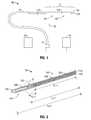
- FIG. 1is a schematic diagram of an ablation system according to an embodiment of the present disclosure
- FIG. 2is a partial, longitudinal cross-sectional view of an energy applicator of the ablation system shown in FIG. 1 according to an embodiment of the present disclosure
- FIG. 3is an enlarged view of the indicated area of detail of FIG. 2 according to an embodiment of the present disclosure
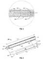
- FIG. 4is a partial, longitudinal cross-sectional (split) view of an elongated body member configured to receive the energy applicator of FIG. 2 according to an embodiment of the present disclosure
- FIG. 5is a partial, perspective view of an electrosurgical device including the elongated body member of FIG. 4 shown with the energy applicator of FIG. 2 (in phantom lines) disposed therein according to an embodiment of the present disclosure;
- FIG. 6is partial, longitudinal cross-sectional view of the electrosurgical device of FIG. 5 according to an embodiment of the present disclosure
- FIG. 7is a schematic diagram of an ablation system including the electrosurgical device of FIGS. 5 and 6 according to an embodiment of the present disclosure
- FIG. 8is a schematic diagram of the electrosurgical device of FIGS. 5 through 7 shown with indicia graduation marks and an indicia alignment mark according to an embodiment of the present disclosure
- FIGS. 9 and 10are schematically-illustrated representations of simulation results showing broadside radiation patterns according to embodiments of the present disclosure.
- FIG. 11is a flowchart illustrating a method of directing energy to a target volume of tissue according to an embodiment of the present disclosure.
- proximalrefers to that portion of the apparatus that is closer to the user and the term “distal” refers to that portion of the apparatus that is further from the user.
- Electromagnetic energyis generally classified by increasing energy or decreasing wavelength into radio waves, microwaves, infrared, visible light, ultraviolet, X-rays and gamma-rays.
- microwavegenerally refers to electromagnetic waves in the frequency range of 300 megahertz (MHz) (3 ⁇ 10 8 cycles/second) to 300 gigahertz (GHz) (3 ⁇ 10 11 cycles/second).
- ablation proceduregenerally refers to any ablation procedure, such as microwave ablation or microwave ablation assisted resection.
- transmission linegenerally refers to any transmission medium that can be used for the propagation of signals from one point to another.
- Various embodiments of the present disclosureprovide electrosurgical devices for treating tissue and methods of directing electromagnetic radiation to a target volume of tissue.
- Embodimentsmay be implemented using electromagnetic radiation at microwave frequencies or at other frequencies.
- An electrosurgical system including an energy applicator, according to various embodiments,is designed and configured to operate between about 500 MHz and about 10 GHz with a directional radiation pattern.
- Various embodiments of the presently disclosed electrosurgical device with a directional radiation patternare suitable for microwave ablation and for use to pre-coagulate tissue for microwave ablation assisted surgical resection.
- various methods described hereinbeloware targeted toward microwave ablation and the complete destruction of target tissue, it is to be understood that methods for directing electromagnetic radiation may be used with other therapies in which the target tissue is partially destroyed or damaged, such as, for example, to prevent the conduction of electrical impulses within heart tissue.
- the teachings of the present disclosuremay also apply to a monopole, helical, or other suitable type of microwave antenna.
- FIG. 1shows an electrosurgical system 10 , according to an embodiment of the present disclosure, which includes an energy applicator or probe 100 .
- Energy applicator 100includes an antenna assembly 12 that is connected by a feedline 110 (or shaft) via a transmission line 15 to a connector 16 , which may further operably connect the probe 100 to a power generating source 28 , e.g., a microwave or radio frequency (RF) electrosurgical generator.
- the power generating source 28is configured to provide microwave energy at an operational frequency from about 500 MHz to about 2500 MHz.
- the power generating source 28is configured to provide microwave energy at an operational frequency from about 500 MHz to about 10 GHz.
- Power generating source 28may be configured to provide various frequencies of electromagnetic energy.
- Transmission line 15may additionally or alternatively provide a conduit (not shown) configured to provide coolant from a coolant source 18 to the probe 100 .
- an end cap or tapered region 120Located at the distal end of the antenna assembly 12 is an end cap or tapered region 120 , which may terminate in a sharp tip 123 to allow for insertion into tissue with minimal resistance.
- a straight probe with a sharp tipthat may be suitable for use as the energy applicator 100 is commercially available under the trademark EvidentTM offered by Covidien.
- the end cap portion or tapered region 120may include other shapes, such as, for example, a tip 123 that is rounded, flat, square, hexagonal, or cylindroconical.
- the antenna assembly 12includes a distal radiating portion 105 and a proximal radiating portion 140 .
- a feedpoint or puck 130may be provided.
- the puck 130having length “L 2 ”, is a junction member that couples the proximal radiating portion 140 and the distal radiating portion 105 .
- Puck 130or portions thereof, may be disposed between the proximal and distal radiating portions, 140 and 105 .
- Puck 130may be formed from any suitable elastomeric or ceramic dielectric material by any suitable process.
- the puck 130is formed by overmolding and includes a thermoplastic elastomer, such as, for example, polyether block amide (e.g., PEBAX®, manufactured by The Arkema Group of Colombes, France), polyetherimide (e.g., ULTEM® and/or EXTEM®, manufactured by SABIC Innovative Plastics of Saudi Arabia) and/or polyimide-based polymer (e.g., VESPEL®, manufactured by E. I. du Pont de Nemours and Company of Wilmington, Del., United States).
- Puck 130may be formed using any suitable overmolding compound by any suitable process, and may include use of a ceramic substrate.
- the antenna assembly 12may be provided with a coolant chamber (not shown).
- the puck 130may include coolant inflow and outflow ports (not shown) to facilitate the flow of coolant into, and out of, the coolant chamber. Examples of coolant chamber and coolant inflow and outflow port embodiments are disclosed in commonly assigned U.S. patent application Ser. No. 12/401,268 filed on Mar. 10, 2009, entitled “COOLED DIELECTRICALLY BUFFERED MICROWAVE DIPOLE ANTENNA”, and U.S. Pat. No. 7,311,703, entitled “DEVICES AND METHODS FOR COOLING MICROWAVE ANTENNAS”.
- the antenna assembly 12may be provided with an outer jacket (not shown) disposed about the distal radiating portion 105 , the puck 130 and/or the proximal radiating portion 140 .
- the outer jacketmay be formed of any suitable material, such as, for example, polymeric or ceramic materials.
- the outer jacketmay be applied by any suitable method, such as, for example, heat shrinking, overmolding, coating, spraying dipping, powder coating, baking and/or film deposition.
- the probe 100is inserted into or placed adjacent to tissue and microwave energy is supplied thereto.
- Ultrasound or computed tomography (CT) guidancemay be used to accurately guide the probe 100 into the area of tissue to be treated.
- Probe 100may be placed percutaneously or surgically, e.g., using conventional surgical techniques by surgical staff.
- a clinicianmay pre-determine the length of time that microwave energy is to be applied.
- Application durationmay depend on many factors such as tumor size and location and whether the tumor was a secondary or primary cancer.
- the duration of microwave energy application using the probe 100may depend on the progress of the heat distribution within the tissue area that is to be destroyed and/or the surrounding tissue.
- Single or multiple probes 100may provide ablations in short procedure times, e.g., a few minutes, to destroy cancerous cells in the target tissue region.
- a plurality of probes 100may be placed in variously arranged configurations to substantially simultaneously ablate a target tissue region, making faster procedures possible. Multiple probes 100 can be used to synergistically create a large ablation or to ablate separate sites simultaneously. Tissue ablation size and geometry is influenced by a variety of factors, such as the energy applicator design, number of energy applicators used simultaneously, time and wattage.
- an embodiment of the antenna assembly 12 of FIG. 1includes an inner conductor 210 , having length “L 3 ”, an outer conductor 260 , having length “L 1 ”, and may include a first dielectric material 240 separating the inner conductor 210 and the outer conductor 260 .
- the inner conductor 210is formed from a first electrically conductive material (e.g., stainless steel) and the outer conductor 260 is formed from a second electrically conductive material (e.g., copper).
- the outer conductor 260coaxially surrounds the inner conductor 210 along a distal portion of the antenna assembly 12 , having length “L 1 ”, as shown in FIG. 2 .
- Inner conductor 210 and the outer conductor 260may be formed from any suitable electrically conductive material.
- First dielectric material 240may be formed from any suitable dielectric material, including, but not limited to, ceramics, water, mica, polyethylene, polyethylene terephthalate, polyimide, polytetrafluoroethylene (PTFE) (e.g., Teflon®, manufactured by E. I. du Pont de Nemours and Company of Wilmington, Del., United States), glass, or metal oxides.
- Antenna assembly 12may be provided with a second dielectric material 290 surrounding the outer conductor 260 and/or the puck 130 , or portions thereof.
- Second dielectric material 290may be formed from any suitable dielectric material.
- the second dielectric material 290is formed from a material with a dielectric constant different than the dielectric constant of the first dielectric material 240 .
- the antenna assembly 12having length “L 4 ”, includes a conductor end portion 280 , which may be formed from any suitable electrically conductive material.
- the conductor end portion 280is coupled to the inner conductor 210 and may be formed of the same material as the inner conductor 210 . As shown in FIG. 2 , the conductor end portion 280 may be spaced apart a length “L 2 ” from the outer conductor 260 by the puck 130 , having length “L 2 ”, disposed therebetween. Tapered region 120 , or portions thereof, may surround a proximal portion of the conductor end portion 280 .
- the conductor end portion 280is substantially cylindrically shaped, and may be formed from stainless steel. The shape and size of the conductor end portion 280 may be varied from the configuration depicted in FIG. 2 . In some embodiments, at least a portion of the conductor end portion 280 is surrounded by the second dielectric material 290 .
- FIG. 4shows an elongated body member 400 , according to an embodiment of the present disclosure, which is configured to receive an energy applicator (e.g., 100 shown in FIG. 1 ), or portions thereof.
- An electrosurgical device that includes the elongated body member 400is shown in FIGS. 5 and 6 .
- the elongated body member 400is substantially tubular, except for a tapered portion 420 tapering from the distal end thereof. Tapered portion 420 may include a tip portion, which may be advantageously configured to facilitate penetration of tissue.
- the surfaces of the tapered portion 420 shown in FIGS. 4 through 6are generally flat, the surfaces of the tapered portion 420 according to various embodiments may be curved or may include a combination of flat, sloped or curved portions. The shape and size of the tapered portion 420 may be varied from the configuration depicted in FIGS. 4 through 6 .
- Elongated body member 400includes a proximal end portion, a distal end portion, wherein the proximal and distal end portions define a longitudinal axis “A-A”, a chamber 480 surrounding and extending along the axis “A-A”, and a body wall 450 surrounding the chamber 480 .
- Chamber 480is configured to receive at least a portion of an energy applicator (e.g., 100 shown in FIG. 1 ).
- the chamber 480is dimensioned and configured to receive an antenna assembly (e.g., 12 shown in FIGS. 5 and 6 ) within the chamber 480 .
- the shape and size of the chamber 480may be varied from the configuration depicted in FIGS. 5 and 6 .
- Body wall 450is provided with at least one opening 440 therethough to allow electromagnetic energy radiated from the energy applicator to transfer into the target volume of tissue (e.g., “T” shown in FIG. 7 ).
- the opening 440is configured for radiating energy in a broadside radiation pattern, such as the non-limiting example directional radiation patterns shown in FIGS. 9 and 10 .
- a substantially slot-shaped opening 440having length “L 5 ” and width “W”, may be positioned at a side portion of the body wall 450 , and may have a longitudinal axis that extends substantially parallel to the axis “A-A”.
- the shape and size of the opening 440may be varied from the configuration depicted in FIGS. 4 and 5 .
- Elongated body member 400may include a plurality of openings 440 .
- the body wall 450is provided with a plurality of elongated slots, which may be spaced longitudinally along the elongated body member 400 .
- the size, shape and/or location of each opening 440may be based on the wavelength of the radiated energy along the antenna radiating portion (e.g., 140 and/or 105 shown in FIG. 2 ).
- the number of openings 440may be based on various factors, such as, for example, the volume of target tissue to be treated, the desired procedure, the wavelength of the electromagnetic energy to be radiated, and the shape and/or dimensions of the openings.
- each opening 440may be based on the location of the opening 440 relative to a distal tip of the antenna assembly 12 .
- the antenna assembly 12is a dipole antenna, and the openings 440 may be configured to encompass any radial angle, length, and positioning with respect to the antenna dipole arms.
- Opening 440may be provided with an electrically nonconductive material 442 .
- Nonconductive material 442may include a nonconductive RF transparent material, e.g., a glass fiber epoxy composite or polyimide.
- the nonconductive material 442substantially entirely fills the recess or void formed by the opening 440 in the elongated body member 400 .
- Opening 440may be filled with the nonconductive material 442 such that the external surface of the elongated body member 400 is substantially smooth.
- Elongated body member 400may include an outer jacket (e.g., 458 shown in FIGS. 5 and 6 ).
- Outer jacket 458may be formed of any suitable electrically conductive material, such as, for example, electrically conducting metallic ceramic and polymeric electrically conductive materials.
- Outer jacket 458may include metal and/or conductive oxide layers.
- Outer jacket 458may be configured to surround the body wall 450 , or portions thereof, and/or the tapered portion 420 , or portions thereof.
- the outer jacket 458is formed of an electrically conductive material and configured to substantially surround the body wall 450 , except for the opening 440 and the electrically nonconductive material 442 disposed therein.
- Elongated body member 400may be a tubular body (e.g., a tubular body member of a catheter assembly) having an outer surface (e.g., 458 shown in FIGS. 5 and 6 ) that includes a single or multiple openings 440 formed therethrough.
- the tubular body memberis formed of an electrically conductive material and/or the outer surface of the tubular body member is formed of an electrically conductive material.
- FIGS. 5 through 7show an electrosurgical device 500 , according to an embodiment of the present disclosure, which is configured to operate with a directional radiation pattern.
- Electrosurgical device 500includes the elongated body member 400 of FIG. 4 and the antenna assembly 12 of FIG. 2 disposed within the chamber 480 of the elongated body member 400 .
- Antenna assembly 12 and the elongated body member 400may be disengageably coupled to each other.
- Electrosurgical device 500may be sufficiently small in diameter to be minimally invasive of the body, which may reduce the preparation time of the patient as might be required for more invasive penetration of the body.
- Electrosurgical device 500may include a moveable sleeve member (not shown) associated with elongated body member 400 and coaxially aligned with the axis “A-A”. Such a sleeve member may either be on the outside or the inside of elongated body member. In some embodiments, the sleeve member may be adapted to be rotationably moveable and/or slideably moveable along the outside of the antenna assembly 12 to various axial positions or various rotational positions to vary the size of the opening 440 with rotation angle. The sleeve member may include a plurality of apertures and may be moveable relative to the elongated body member 400 to various positions, thereby providing variably dimensioned electromagnetic “windows” within the opening 440 . In other embodiments, the elongated body member 400 itself may be adapted to be rotationably moveable and/or slideably moveable along the outside of the antenna assembly 12 .
- FIG. 7shows an electrosurgical system 700 , according to an embodiment of the present disclosure, which includes the electrosurgical device 500 of FIGS. 5 and 6 .
- Electrosurgical device 500is coupled to a connector 16 via a transmission line 15 , which may further connect the electrosurgical device 500 to a power generating source 28 , e.g., a microwave or RF electrosurgical generator.
- a power generating source 28e.g., a microwave or RF electrosurgical generator.
- the electrosurgical device 500 of the electrosurgical system 700is inserted into or placed adjacent to tissue “T” and energy is supplied thereto.
- Electrosurgical device 500may be placed percutaneously or surgically. Ultrasound or computed tomography (CT) guidance may be used to accurately guide the electrosurgical device 500 into the area of tissue “T” to be treated.
- CTcomputed tomography
- FIG. 8shows an electrosurgical device 800 , which is similar to the electrosurgical device 500 of FIGS. 5 through 7 , except for the indicia alignment mark 810 and the indicia graduation marks 880 on the proximal end of the electrosurgical device 800 .
- Indicia alignment mark 810 and/or the indicia graduation marks 880may be carried on or inscribed into the elongated body member of the electrosurgical device 800 .
- the electrosurgical device 800includes a plurality of indicia graduation marks 880 defining units of linear measure, which may be inscribed substantially circumferentially about the elongated body member.
- Indicia graduation marks 880may be used to indicate the relative position of the opening 440 with respect to the surface of the tissue “T”.
- the indicia graduation marks 880are used to indicate the position of the distal end of the opening 440 relative to the surface of the tissue “T”. Indicia graduation marks 880 may be arranged to form an incremental pattern using any standard measure of length, e.g., inches or centimeters.
- the electrosurgical device 800includes an indicia alignment mark 810 , e.g., a colored stripe, which is readily visible along the proximal end of the elongated body member.
- Indicia alignment mark 810is positioned on the elongated body member such that the longitudinal axis of the alignment mark 810 substantially aligns with the longitudinal axis of the opening 440 , to provide a visual cue to the surgeon to allow orientation of the direction of flow of the energy to coincide with the indicia alignment mark 810 .
- one or more of the indicia graduation marks 880may overlap the indicia alignment mark 810 .
- the shape and size of the indicia alignment mark 810 and the indicia graduation marks 880may be varied from the configurations depicted in FIG. 8 .
- FIGS. 9 and 10are schematically-illustrated representations of simulation results showing directional radiation patterns. The illustrated results are based on a simulation that modeled operation of an electrosurgical device 600 , which is configured to operate with a directional radiation pattern. Electrosurgical device 600 shown in FIGS. 9 and 10 is similar to the electrosurgical device 500 of FIGS. 5 through 7 and further description thereof is omitted in the interests of brevity.
- FIG. 11is a flowchart illustrating a method of directing energy to a target volume of tissue, according to an embodiment of the present disclosure.
- an electrosurgical devicee.g., 500 shown in FIGS. 5 through 7
- the deviceincludes an elongated body member (e.g., 400 shown in FIG. 4 ) having a body wall defining a chamber therein, and an antenna assembly disposed in the chamber, wherein the elongated body member includes an opening (e.g., 440 shown in FIG. 7 ) in the body wall.
- the deviceis positioned to the target volume of tissue.
- the electrosurgical devicemay be inserted directly into tissue (e.g., “T” shown in FIG. 7 ), inserted through a lumen, e.g., a vein, needle or catheter, placed into the body during surgery by a clinician, or positioned in the body by other suitable methods known in the art.
- the electrosurgical deviceis configured to operate with a directional radiation pattern.
- the electrosurgical deviceis configured to operate with a broadside radiation pattern.
- the catheter or needlecontains the opening to allow a directional radiation pattern.
- step 1130energy from an energy source (e.g., 28 shown in FIG. 7 ) is transmitted to the antenna assembly.
- the energy sourcemay be any suitable electrosurgical generator for generating an output signal.
- the energy sourceis a microwave energy source, and may be configured to provide microwave energy at an operational frequency from about 500 MHz to about 10 GHz.
- the energy from the energy sourceis caused to radiate through the opening in the elongated body member.
- the openingis configured for radiating energy in a broadside radiation pattern.
- the above-described electrosurgical devices for treating tissue and methods of directing electromagnetic radiation to a target volume of tissuemay be used to provide directional microwave ablation, wherein the heating zone may be focused to one side of the electrosurgical device, thereby allowing clinicians to target small and/or hard tumors without having to penetrate the tumor directly or kill more healthy tissue than necessary.
- the presently disclosed electrosurgical devicesmay allow clinicians to avoid ablating critical structures, such as large vessels, healthy organs or vital membrane barriers, by placing the electrosurgical device between the tumor and critical structure and directing the electromagnetic radiation toward the tumor and away from the critical structure.
- the electrosurgical device 500may be rotatable about axis “A-A” such that the directional radiation pattern rotates therewith.
Landscapes
- Health & Medical Sciences (AREA)
- Surgery (AREA)
- Life Sciences & Earth Sciences (AREA)
- Engineering & Computer Science (AREA)
- Biomedical Technology (AREA)
- Molecular Biology (AREA)
- Nuclear Medicine, Radiotherapy & Molecular Imaging (AREA)
- Veterinary Medicine (AREA)
- Physics & Mathematics (AREA)
- Heart & Thoracic Surgery (AREA)
- Medical Informatics (AREA)
- Otolaryngology (AREA)
- Animal Behavior & Ethology (AREA)
- General Health & Medical Sciences (AREA)
- Public Health (AREA)
- Electromagnetism (AREA)
- Cardiology (AREA)
- Plasma & Fusion (AREA)
- Surgical Instruments (AREA)
Abstract
Description
Claims (7)
Priority Applications (3)
| Application Number | Priority Date | Filing Date | Title |
|---|---|---|---|
| US13/567,624US8690869B2 (en) | 2009-06-02 | 2012-08-06 | Electrosurgical devices with directional radiation pattern |
| US14/242,048US9526575B2 (en) | 2009-06-02 | 2014-04-01 | Electrosurgical devices with directional radiation pattern |
| US15/382,954US10736694B2 (en) | 2009-06-02 | 2016-12-19 | Electrosurgical devices with directional radiation pattern |
Applications Claiming Priority (2)
| Application Number | Priority Date | Filing Date | Title |
|---|---|---|---|
| US12/476,960US8235981B2 (en) | 2009-06-02 | 2009-06-02 | Electrosurgical devices with directional radiation pattern |
| US13/567,624US8690869B2 (en) | 2009-06-02 | 2012-08-06 | Electrosurgical devices with directional radiation pattern |
Related Parent Applications (1)
| Application Number | Title | Priority Date | Filing Date |
|---|---|---|---|
| US12/476,960ContinuationUS8235981B2 (en) | 2009-06-02 | 2009-06-02 | Electrosurgical devices with directional radiation pattern |
Related Child Applications (1)
| Application Number | Title | Priority Date | Filing Date |
|---|---|---|---|
| US14/242,048DivisionUS9526575B2 (en) | 2009-06-02 | 2014-04-01 | Electrosurgical devices with directional radiation pattern |
Publications (2)
| Publication Number | Publication Date |
|---|---|
| US20120303014A1 US20120303014A1 (en) | 2012-11-29 |
| US8690869B2true US8690869B2 (en) | 2014-04-08 |
Family
ID=42674644
Family Applications (4)
| Application Number | Title | Priority Date | Filing Date |
|---|---|---|---|
| US12/476,960Expired - Fee RelatedUS8235981B2 (en) | 2009-06-02 | 2009-06-02 | Electrosurgical devices with directional radiation pattern |
| US13/567,624ActiveUS8690869B2 (en) | 2009-06-02 | 2012-08-06 | Electrosurgical devices with directional radiation pattern |
| US14/242,048Expired - Fee RelatedUS9526575B2 (en) | 2009-06-02 | 2014-04-01 | Electrosurgical devices with directional radiation pattern |
| US15/382,954Active2031-09-28US10736694B2 (en) | 2009-06-02 | 2016-12-19 | Electrosurgical devices with directional radiation pattern |
Family Applications Before (1)
| Application Number | Title | Priority Date | Filing Date |
|---|---|---|---|
| US12/476,960Expired - Fee RelatedUS8235981B2 (en) | 2009-06-02 | 2009-06-02 | Electrosurgical devices with directional radiation pattern |
Family Applications After (2)
| Application Number | Title | Priority Date | Filing Date |
|---|---|---|---|
| US14/242,048Expired - Fee RelatedUS9526575B2 (en) | 2009-06-02 | 2014-04-01 | Electrosurgical devices with directional radiation pattern |
| US15/382,954Active2031-09-28US10736694B2 (en) | 2009-06-02 | 2016-12-19 | Electrosurgical devices with directional radiation pattern |
Country Status (5)
| Country | Link |
|---|---|
| US (4) | US8235981B2 (en) |
| EP (1) | EP2258300B1 (en) |
| JP (1) | JP5630900B2 (en) |
| AU (1) | AU2010202190B2 (en) |
| CA (1) | CA2706194C (en) |
Cited By (4)
| Publication number | Priority date | Publication date | Assignee | Title |
|---|---|---|---|---|
| US9526575B2 (en) | 2009-06-02 | 2016-12-27 | Covidien Lp | Electrosurgical devices with directional radiation pattern |
| US10022186B2 (en) | 2008-08-28 | 2018-07-17 | Covidien Lp | Microwave antenna with cooled handle |
| WO2020049283A1 (en) | 2018-09-05 | 2020-03-12 | Emblation Limited | Microwave apparatus, system and manufacturing method |
| US10631922B2 (en) | 2008-02-07 | 2020-04-28 | Covidien Lp | Endoscopic instrument for tissue identification |
Families Citing this family (78)
| Publication number | Priority date | Publication date | Assignee | Title |
|---|---|---|---|---|
| US7197363B2 (en) | 2002-04-16 | 2007-03-27 | Vivant Medical, Inc. | Microwave antenna having a curved configuration |
| US7553309B2 (en) | 2004-10-08 | 2009-06-30 | Covidien Ag | Electrosurgical system employing multiple electrodes and method thereof |
| US10363092B2 (en) | 2006-03-24 | 2019-07-30 | Neuwave Medical, Inc. | Transmission line with heat transfer ability |
| US11389235B2 (en) | 2006-07-14 | 2022-07-19 | Neuwave Medical, Inc. | Energy delivery systems and uses thereof |
| US10376314B2 (en) | 2006-07-14 | 2019-08-13 | Neuwave Medical, Inc. | Energy delivery systems and uses thereof |
| US9622813B2 (en) | 2007-11-01 | 2017-04-18 | Covidien Lp | Method for volume determination and geometric reconstruction |
| US8280525B2 (en) | 2007-11-16 | 2012-10-02 | Vivant Medical, Inc. | Dynamically matched microwave antenna for tissue ablation |
| US8945111B2 (en) | 2008-01-23 | 2015-02-03 | Covidien Lp | Choked dielectric loaded tip dipole microwave antenna |
| US8435237B2 (en) | 2008-01-29 | 2013-05-07 | Covidien Lp | Polyp encapsulation system and method |
| US9949794B2 (en) | 2008-03-27 | 2018-04-24 | Covidien Lp | Microwave ablation devices including expandable antennas and methods of use |
| US8192427B2 (en) | 2008-06-09 | 2012-06-05 | Tyco Healthcare Group Lp | Surface ablation process with electrode cooling methods |
| US9173706B2 (en) | 2008-08-25 | 2015-11-03 | Covidien Lp | Dual-band dipole microwave ablation antenna |
| US8403924B2 (en) | 2008-09-03 | 2013-03-26 | Vivant Medical, Inc. | Shielding for an isolation apparatus used in a microwave generator |
| US8202270B2 (en) | 2009-02-20 | 2012-06-19 | Vivant Medical, Inc. | Leaky-wave antennas for medical applications |
| US8197473B2 (en) | 2009-02-20 | 2012-06-12 | Vivant Medical, Inc. | Leaky-wave antennas for medical applications |
| US9277969B2 (en) | 2009-04-01 | 2016-03-08 | Covidien Lp | Microwave ablation system with user-controlled ablation size and method of use |
| US8463396B2 (en) | 2009-05-06 | 2013-06-11 | Covidien LLP | Power-stage antenna integrated system with high-strength shaft |
| US8246615B2 (en) | 2009-05-19 | 2012-08-21 | Vivant Medical, Inc. | Tissue impedance measurement using a secondary frequency |
| US8292881B2 (en) | 2009-05-27 | 2012-10-23 | Vivant Medical, Inc. | Narrow gauge high strength choked wet tip microwave ablation antenna |
| EP3549544B1 (en) | 2009-07-28 | 2021-01-06 | Neuwave Medical, Inc. | DEVICE FOR ABLATION |
| US8328799B2 (en) | 2009-08-05 | 2012-12-11 | Vivant Medical, Inc. | Electrosurgical devices having dielectric loaded coaxial aperture with distally positioned resonant structure |
| US9031668B2 (en)* | 2009-08-06 | 2015-05-12 | Covidien Lp | Vented positioner and spacer and method of use |
| US8069553B2 (en) | 2009-09-09 | 2011-12-06 | Vivant Medical, Inc. | Method for constructing a dipole antenna |
| US9113925B2 (en)* | 2009-09-09 | 2015-08-25 | Covidien Lp | System and method for performing an ablation procedure |
| US8355803B2 (en) | 2009-09-16 | 2013-01-15 | Vivant Medical, Inc. | Perfused core dielectrically loaded dipole microwave antenna probe |
| US9095359B2 (en) | 2009-09-18 | 2015-08-04 | Covidien Lp | Tissue ablation system with energy distribution |
| US8394087B2 (en)* | 2009-09-24 | 2013-03-12 | Vivant Medical, Inc. | Optical detection of interrupted fluid flow to ablation probe |
| US9113926B2 (en) | 2009-09-29 | 2015-08-25 | Covidien Lp | Management of voltage standing wave ratio at skin surface during microwave ablation |
| US8568398B2 (en) | 2009-09-29 | 2013-10-29 | Covidien Lp | Flow rate monitor for fluid cooled microwave ablation probe |
| US8568401B2 (en) | 2009-10-27 | 2013-10-29 | Covidien Lp | System for monitoring ablation size |
| US8382750B2 (en)* | 2009-10-28 | 2013-02-26 | Vivant Medical, Inc. | System and method for monitoring ablation size |
| US8430871B2 (en) | 2009-10-28 | 2013-04-30 | Covidien Lp | System and method for monitoring ablation size |
| US8394092B2 (en)* | 2009-11-17 | 2013-03-12 | Vivant Medical, Inc. | Electromagnetic energy delivery devices including an energy applicator array and electrosurgical systems including same |
| US8764744B2 (en) | 2010-01-25 | 2014-07-01 | Covidien Lp | System for monitoring ablation size |
| US8491579B2 (en) | 2010-02-05 | 2013-07-23 | Covidien Lp | Electrosurgical devices with choke shorted to biological tissue |
| US8968288B2 (en) | 2010-02-19 | 2015-03-03 | Covidien Lp | Ablation devices with dual operating frequencies, systems including same, and methods of adjusting ablation volume using same |
| US8617153B2 (en) | 2010-02-26 | 2013-12-31 | Covidien Lp | Tunable microwave ablation probe |
| US8728067B2 (en) | 2010-03-08 | 2014-05-20 | Covidien Lp | Microwave antenna probe having a deployable ground plane |
| US8409188B2 (en) | 2010-03-26 | 2013-04-02 | Covidien Lp | Ablation devices with adjustable radiating section lengths, electrosurgical systems including same, and methods of adjusting ablation fields using same |
| US10039601B2 (en) | 2010-03-26 | 2018-08-07 | Covidien Lp | Ablation devices with adjustable radiating section lengths, electrosurgical systems including same, and methods of adjusting ablation fields using same |
| ES2856026T3 (en) | 2010-05-03 | 2021-09-27 | Neuwave Medical Inc | Power supply systems |
| US9192436B2 (en) | 2010-05-25 | 2015-11-24 | Covidien Lp | Flow rate verification monitor for fluid-cooled microwave ablation probe |
| US8652127B2 (en) | 2010-05-26 | 2014-02-18 | Covidien Lp | System and method for chemically cooling an ablation antenna |
| US9241762B2 (en) | 2010-06-03 | 2016-01-26 | Covidien Lp | Specific absorption rate measurement and energy-delivery device characterization using image analysis |
| US8672933B2 (en) | 2010-06-30 | 2014-03-18 | Covidien Lp | Microwave antenna having a reactively-loaded loop configuration |
| US10588684B2 (en) | 2010-07-19 | 2020-03-17 | Covidien Lp | Hydraulic conductivity monitoring to initiate tissue division |
| US8968289B2 (en) | 2010-10-22 | 2015-03-03 | Covidien Lp | Microwave spacers and methods of use |
| JP6314200B2 (en)* | 2010-12-23 | 2018-04-18 | コビディエン エルピー | Microwave field detection needle assembly, method for manufacturing the same, method for adjusting an irradiation ablation region in tissue using the same, and system including the same |
| US9017319B2 (en) | 2011-01-05 | 2015-04-28 | Covidien Lp | Energy-delivery devices with flexible fluid-cooled shaft, inflow/outflow junctions suitable for use with same, and systems including same |
| US9770294B2 (en) | 2011-01-05 | 2017-09-26 | Covidien Lp | Energy-delivery devices with flexible fluid-cooled shaft, inflow/outflow junctions suitable for use with same, and systems including same |
| US8932281B2 (en)* | 2011-01-05 | 2015-01-13 | Covidien Lp | Energy-delivery devices with flexible fluid-cooled shaft, inflow/outflow junctions suitable for use with same, and systems including same |
| US9011421B2 (en) | 2011-01-05 | 2015-04-21 | Covidien Lp | Energy-delivery devices with flexible fluid-cooled shaft, inflow/outflow junctions suitable for use with same, and systems including same |
| US9028476B2 (en) | 2011-02-03 | 2015-05-12 | Covidien Lp | Dual antenna microwave resection and ablation device, system and method of use |
| US9192438B2 (en) | 2011-12-21 | 2015-11-24 | Neuwave Medical, Inc. | Energy delivery systems and uses thereof |
| US9113931B2 (en) | 2012-01-06 | 2015-08-25 | Covidien Lp | System and method for treating tissue using an expandable antenna |
| US9119648B2 (en) | 2012-01-06 | 2015-09-01 | Covidien Lp | System and method for treating tissue using an expandable antenna |
| US8906008B2 (en)* | 2012-05-22 | 2014-12-09 | Covidien Lp | Electrosurgical instrument |
| AU2014317930B2 (en) | 2013-09-06 | 2018-11-08 | Covidien Lp | Microwave ablation catheter, handle, and system |
| US10765477B2 (en) | 2014-03-10 | 2020-09-08 | Wisconsin Alumni Research Foundation | Microwave ablation antenna system |
| CN104157690B (en)* | 2014-08-14 | 2017-05-10 | 电子科技大学 | Strain NLDMOS device with groove structure and manufacturing method thereof |
| US10813691B2 (en)* | 2014-10-01 | 2020-10-27 | Covidien Lp | Miniaturized microwave ablation assembly |
| CN113367788B (en) | 2015-10-26 | 2024-09-06 | 纽韦弗医疗设备公司 | Energy delivery systems and uses thereof |
| EP3407794A4 (en) | 2016-04-14 | 2019-11-06 | Focal Therapeutics, Inc. | TISSUE LOCATION DEVICE AND METHOD OF USE |
| US10531917B2 (en) | 2016-04-15 | 2020-01-14 | Neuwave Medical, Inc. | Systems and methods for energy delivery |
| GB201614581D0 (en)* | 2016-08-26 | 2016-10-12 | Emblation Ltd | Microwave instrument |
| US11058487B2 (en)* | 2017-03-09 | 2021-07-13 | Wisconsin Alumni Research Foundation | Microwave ablation antenna system with reflector and slot |
| CN106974725B (en)* | 2017-04-21 | 2019-12-27 | 四川大学华西医院 | Unilateral heating multiple-gap hemostatic needle |
| US10716619B2 (en) | 2017-06-19 | 2020-07-21 | Covidien Lp | Microwave and radiofrequency energy-transmitting tissue ablation systems |
| US11147621B2 (en) | 2017-11-02 | 2021-10-19 | Covidien Lp | Systems and methods for ablating tissue |
| US10707581B2 (en) | 2018-01-03 | 2020-07-07 | Wisconsin Alumni Research Foundation | Dipole antenna for microwave ablation |
| CN108523990B (en)* | 2018-01-30 | 2020-08-07 | 青岛大学附属医院 | A microwave ablation apparatus for treating uterine fibroids |
| US11672596B2 (en) | 2018-02-26 | 2023-06-13 | Neuwave Medical, Inc. | Energy delivery devices with flexible and adjustable tips |
| EP3639729A1 (en)* | 2018-10-16 | 2020-04-22 | Koninklijke Philips N.V. | Energy transmission for an interventional device for medical interventions |
| US11382682B2 (en) | 2018-11-28 | 2022-07-12 | Boston Scientific Scimed, Inc. | Closed irrigated radiofrequency bipolar tined ablation probe |
| US11957409B2 (en)* | 2018-12-19 | 2024-04-16 | Boston Scientific Scimed, Inc. | Irrigation cooling structure for microwave ablation tissue probe |
| US11832879B2 (en) | 2019-03-08 | 2023-12-05 | Neuwave Medical, Inc. | Systems and methods for energy delivery |
| CN113924057B (en) | 2019-05-24 | 2025-01-14 | 堪萨斯州立大学研究基金会 | Minimally invasive microwave ablation device |
| CN114652434B (en)* | 2022-02-16 | 2023-09-26 | 电子科技大学 | A multi-window microwave ablation method and device based on MEMS microneedle beam |
Citations (154)
| Publication number | Priority date | Publication date | Assignee | Title |
|---|---|---|---|---|
| DE390937C (en) | 1922-10-13 | 1924-03-03 | Adolf Erb | Device for internal heating of furnace furnaces for hardening, tempering, annealing, quenching and melting |
| DE1099658B (en) | 1959-04-29 | 1961-02-16 | Siemens Reiniger Werke Ag | Automatic switch-on device for high-frequency surgical devices |
| FR1275415A (en) | 1960-09-26 | 1961-11-10 | Device for detecting disturbances for electrical installations, in particular electrosurgery | |
| DE1139927B (en) | 1961-01-03 | 1962-11-22 | Friedrich Laber | High-frequency surgical device |
| DE1149832B (en) | 1961-02-25 | 1963-06-06 | Siemens Reiniger Werke Ag | High frequency surgical apparatus |
| FR1347865A (en) | 1962-11-22 | 1964-01-04 | Improvements to diathermo-coagulation devices | |
| DE1439302A1 (en) | 1963-10-26 | 1969-01-23 | Siemens Ag | High-frequency surgical device |
| SU401367A1 (en) | 1971-10-05 | 1973-10-12 | Тернопольский государственный медицинский институт | BIAKTIVNYE ELECTRO SURGICAL INSTRUMENT |
| DE2439587A1 (en) | 1973-08-23 | 1975-02-27 | Matburn Holdings Ltd | ELECTROSURGICAL DEVICE |
| US3870977A (en) | 1973-09-25 | 1975-03-11 | Times Wire And Cable Companay | Radiating coaxial cable |
| DE2455174A1 (en) | 1973-11-21 | 1975-05-22 | Termiflex Corp | INPUT / OUTPUT DEVICE FOR DATA EXCHANGE WITH DATA PROCESSING DEVICES |
| DE2407559A1 (en) | 1974-02-16 | 1975-08-28 | Dornier System Gmbh | Tissue heat treatment probe - has water cooling system which ensures heat development only in treated tissues |
| DE2415263A1 (en) | 1974-03-29 | 1975-10-02 | Aesculap Werke Ag | Surgical H.F. coagulation probe has electrode tongs - with exposed ends of insulated conductors forming tong-jaws |
| DE2429021A1 (en) | 1974-06-18 | 1976-01-08 | Erbe Elektromedizin | Remote control for HF surgical instruments - uses cable with two conductors at most |
| FR2235669B1 (en) | 1973-07-07 | 1976-05-07 | Lunacek Boris | |
| DE2460481A1 (en) | 1974-12-20 | 1976-06-24 | Delma Elektro Med App | Electrode grip for remote HF surgical instrument switching - has shaped insulated piece with contact ring of sterilizable (silicon) rubber |
| DE2602517A1 (en) | 1975-01-23 | 1976-07-29 | Dentsply Int Inc | ELECTROSURGICAL DEVICE |
| DE2504280A1 (en) | 1975-02-01 | 1976-08-05 | Hans Heinrich Prof Dr Meinke | DEVICE FOR ELECTRIC TISSUE CUTTING IN SURGERY |
| DE2627679A1 (en) | 1975-06-26 | 1977-01-13 | Marcel Lamidey | HEMATISTIC HIGH FREQUENCY EXTRACTOR FORCEPS |
| DE2540968A1 (en) | 1975-09-13 | 1977-03-17 | Erbe Elektromedizin | Circuit for bipolar coagulation tweezers - permits preparation of tissues prior to coagulation |
| FR2276027B3 (en) | 1974-06-25 | 1977-05-06 | Medical Plastics Inc | |
| DE2820908A1 (en) | 1977-05-16 | 1978-11-23 | Joseph Skovajsa | DEVICE FOR THE LOCAL TREATMENT OF A PATIENT IN PARTICULAR FOR ACUPUNCTURE OR AURICULAR THERAPY |
| DE2803275A1 (en) | 1978-01-26 | 1979-08-02 | Aesculap Werke Ag | HF surgical appts. with active treatment and patient electrodes - has sensor switching generator to small voltage when hand-operated switch is closed |
| DE2823291A1 (en) | 1978-05-27 | 1979-11-29 | Rainer Ing Grad Koch | Coagulation instrument automatic HF switching circuit - has first lead to potentiometer and second to transistor base |
| SU727201A2 (en) | 1977-11-02 | 1980-04-15 | Киевский Научно-Исследовательский Институт Нейрохирургии | Electric surgical apparatus |
| US4204549A (en) | 1977-12-12 | 1980-05-27 | Rca Corporation | Coaxial applicator for microwave hyperthermia |
| FR2313708B1 (en) | 1975-06-02 | 1980-07-04 | Sybron Corp | |
| DE2946728A1 (en) | 1979-11-20 | 1981-05-27 | Erbe Elektromedizin GmbH & Co KG, 7400 Tübingen | HF surgical appts. for use with endoscope - provides cutting or coagulation current at preset intervals and of selected duration |
| US4311154A (en) | 1979-03-23 | 1982-01-19 | Rca Corporation | Nonsymmetrical bulb applicator for hyperthermic treatment of the body |
| DE3143421A1 (en) | 1980-11-04 | 1982-05-27 | The Agency of Industrial Science and Technology, Tokyo | Laser scalpel |
| DE3045996A1 (en) | 1980-12-05 | 1982-07-08 | Medic Eschmann Handelsgesellschaft für medizinische Instrumente mbH, 2000 Hamburg | Electro-surgical scalpel instrument - has power supply remotely controlled by surgeon |
| FR2517953A1 (en) | 1981-12-10 | 1983-06-17 | Alvar Electronic | Diaphanometer for optical examination of breast tissue structure - measures tissue transparency using two plates and optical fibre bundle cooperating with photoelectric cells |
| FR2502935B1 (en) | 1981-03-31 | 1985-10-04 | Dolley Roger | METHOD AND DEVICE FOR CONTROLLING THE COAGULATION OF TISSUES USING A HIGH FREQUENCY CURRENT |
| FR2573301B3 (en) | 1984-11-16 | 1987-04-30 | Lamidey Gilles | SURGICAL PLIERS AND ITS CONTROL AND CONTROL APPARATUS |
| DE3120102C2 (en) | 1981-05-20 | 1987-08-20 | Fischer Met Gmbh, 7800 Freiburg, De | |
| EP0246350A1 (en) | 1986-05-23 | 1987-11-25 | Erbe Elektromedizin GmbH. | Coagulation electrode |
| DE8712328U1 (en) | 1987-09-11 | 1988-02-18 | Jakoubek, Franz, 7201 Emmingen-Liptingen | Endoscopy forceps |
| US4743725A (en) | 1985-12-05 | 1988-05-10 | Skandinavisk Torkteknik Ab | Coaxial line microwave heating applicator with asymmetrical radiation pattern |
| DE3711511C1 (en) | 1987-04-04 | 1988-06-30 | Hartmann & Braun Ag | Method for determining gas concentrations in a gas mixture and sensor for measuring thermal conductivity |
| US4754752A (en) | 1986-07-28 | 1988-07-05 | Robert Ginsburg | Vascular catheter |
| DE3510586C2 (en) | 1985-03-23 | 1988-07-28 | Erbe Elektromedizin Gmbh, 7400 Tuebingen, De | |
| US4825880A (en) | 1987-06-19 | 1989-05-02 | The Regents Of The University Of California | Implantable helical coil microwave antenna |
| US4934365A (en) | 1988-06-30 | 1990-06-19 | Massachusetts Institute Of Technology | Non-invasive hyperthermia method and apparatus |
| US5041089A (en) | 1987-12-11 | 1991-08-20 | Devices For Vascular Intervention, Inc. | Vascular dilation catheter construction |
| US5057106A (en) | 1986-02-27 | 1991-10-15 | Kasevich Associates, Inc. | Microwave balloon angioplasty |
| US5097845A (en) | 1987-10-15 | 1992-03-24 | Labthermics Technologies | Microwave hyperthermia probe |
| EP0481685A1 (en) | 1990-10-15 | 1992-04-22 | Cook Incorporated | Medical device for localizing a lesion |
| JPH055106Y2 (en) | 1986-02-28 | 1993-02-09 | ||
| DE4238263A1 (en) | 1991-11-15 | 1993-05-19 | Minnesota Mining & Mfg | Adhesive comprising hydrogel and crosslinked polyvinyl:lactam - is used in electrodes for biomedical application providing low impedance and good mechanical properties when water and/or moisture is absorbed from skin |
| EP0521264A3 (en) | 1991-07-03 | 1993-06-16 | W.L. Gore & Associates Gmbh | Antenna device with feed |
| EP0556705A1 (en) | 1992-02-20 | 1993-08-25 | DELMA ELEKTRO-UND MEDIZINISCHE APPARATEBAU GESELLSCHAFT mbH | High frequency surgery device |
| EP0558429A1 (en) | 1992-02-26 | 1993-09-01 | PECHINEY RECHERCHE (Groupement d'Intérêt Economique géré par l'ordonnance no. 67-821 du 23 Septembre 1967) | Method of simultaneous measuring of electrical resistivety and thermal conductivity |
| US5249585A (en) | 1988-07-28 | 1993-10-05 | Bsd Medical Corporation | Urethral inserted applicator for prostate hyperthermia |
| JPH0540112Y2 (en) | 1987-03-03 | 1993-10-12 | ||
| EP0572131A1 (en) | 1992-05-21 | 1993-12-01 | Everest Medical Corporation | Surgical scissors with bipolar coagulation feature |
| US5369251A (en)* | 1992-09-14 | 1994-11-29 | Kdc Technology Corp. | Microwave interstitial hyperthermia probe |
| JPH06343644A (en) | 1993-05-04 | 1994-12-20 | Gyrus Medical Ltd | Surgical peritoneoscope equipment |
| DE4303882C2 (en) | 1993-02-10 | 1995-02-09 | Kernforschungsz Karlsruhe | Combination instrument for separation and coagulation for minimally invasive surgery |
| DE3604823C2 (en) | 1986-02-15 | 1995-06-01 | Lindenmeier Heinz | High frequency generator with automatic power control for high frequency surgery |
| JPH07265328A (en) | 1993-11-01 | 1995-10-17 | Gyrus Medical Ltd | Electrode assembly for electric surgery device and electric surgery device using it |
| JPH0856955A (en) | 1994-06-29 | 1996-03-05 | Gyrus Medical Ltd | Electric surgical apparatus |
| US5500012A (en) | 1992-07-15 | 1996-03-19 | Angeion Corporation | Ablation catheter system |
| JPH08252263A (en) | 1994-12-21 | 1996-10-01 | Gyrus Medical Ltd | Electronic surgical incision instrument and electronic surgical incision device using the same |
| DE29616210U1 (en) | 1996-09-18 | 1996-11-14 | Olympus Winter & Ibe Gmbh, 22045 Hamburg | Handle for surgical instruments |
| US5588432A (en) | 1988-03-21 | 1996-12-31 | Boston Scientific Corporation | Catheters for imaging, sensing electrical potentials, and ablating tissue |
| JPH0910223A (en) | 1995-06-23 | 1997-01-14 | Gyrus Medical Ltd | Generator and system for electric operation |
| DE19608716C1 (en) | 1996-03-06 | 1997-04-17 | Aesculap Ag | Bipolar surgical holding instrument |
| US5658278A (en) | 1992-12-01 | 1997-08-19 | Cardiac Pathways, Inc. | Catheter for RF ablation with cooled electrode and method |
| DE3904558C2 (en) | 1989-02-15 | 1997-09-18 | Lindenmeier Heinz | Automatically power-controlled high-frequency generator for high-frequency surgery |
| EP0541930B1 (en) | 1991-10-17 | 1998-03-25 | Smith & Nephew, Inc. | Transmission link for use in surgical instruments |
| DE19751106A1 (en) | 1996-11-27 | 1998-05-28 | Eastman Kodak Co | Laser printer with array of laser diodes |
| US5776176A (en) | 1996-06-17 | 1998-07-07 | Urologix Inc. | Microwave antenna for arterial for arterial microwave applicator |
| DE19717411A1 (en) | 1997-04-25 | 1998-11-05 | Aesculap Ag & Co Kg | Monitoring of thermal loading of patient tissue in contact region of neutral electrode of HF treatment unit |
| DE3942998C2 (en) | 1989-12-27 | 1998-11-26 | Delma Elektro Med App | High frequency electrosurgical unit |
| DE19751108A1 (en) | 1997-11-18 | 1999-05-20 | Beger Frank Michael Dipl Desig | Electrosurgical operation tool, especially for diathermy |
| DE19801173C1 (en) | 1998-01-15 | 1999-07-15 | Kendall Med Erzeugnisse Gmbh | Clamp connector for film electrodes |
| JPH11244298A (en) | 1997-12-19 | 1999-09-14 | Gyrus Medical Ltd | Electric surgical instrument |
| EP0836868A3 (en) | 1996-10-18 | 1999-11-24 | Gebr. Berchtold GmbH & Co. | High frequency surgical apparatus and method for operating same |
| DE19848540A1 (en) | 1998-10-21 | 2000-05-25 | Reinhard Kalfhaus | Circuit layout and method for operating a single- or multiphase current inverter connects an AC voltage output to a primary winding and current and a working resistance to a transformer's secondary winding and current. |
| US6097985A (en) | 1999-02-09 | 2000-08-01 | Kai Technologies, Inc. | Microwave systems for medical hyperthermia, thermotherapy and diagnosis |
| JP2000350732A (en) | 1999-05-21 | 2000-12-19 | Gyrus Medical Ltd | Electrosurgical system, generator for electrosurgery, and method for cutting or excising tissue by electrosurgery |
| JP2001008944A (en) | 1999-05-28 | 2001-01-16 | Gyrus Medical Ltd | Electric surgical signal generator and electric surgical system |
| US6181970B1 (en) | 1999-02-09 | 2001-01-30 | Kai Technologies, Inc. | Microwave devices for medical hyperthermia, thermotherapy and diagnosis |
| JP2001029356A (en) | 1999-06-11 | 2001-02-06 | Gyrus Medical Ltd | Electric and surgical signal generator |
| US6230060B1 (en) | 1999-10-22 | 2001-05-08 | Daniel D. Mawhinney | Single integrated structural unit for catheter incorporating a microwave antenna |
| JP2001128990A (en) | 1999-05-28 | 2001-05-15 | Gyrus Medical Ltd | Electro surgical instrument and electrosurgical tool converter |
| US6233490B1 (en) | 1999-02-09 | 2001-05-15 | Kai Technologies, Inc. | Microwave antennas for medical hyperthermia, thermotherapy and diagnosis |
| DE4339049C2 (en) | 1993-11-16 | 2001-06-28 | Erbe Elektromedizin | Surgical system configuration facility |
| US6289249B1 (en) | 1996-04-17 | 2001-09-11 | The United States Of America As Represented By The Administrator Of The National Aeronautics And Space Administration | Transcatheter microwave antenna |
| US6383182B1 (en) | 1998-10-23 | 2002-05-07 | Afx Inc. | Directional microwave ablation instrument with off-set energy delivery portion |
| US20020087151A1 (en) | 2000-12-29 | 2002-07-04 | Afx, Inc. | Tissue ablation apparatus with a sliding ablation instrument and method |
| US6471696B1 (en) | 2000-04-12 | 2002-10-29 | Afx, Inc. | Microwave ablation instrument with a directional radiation pattern |
| US20030032951A1 (en) | 1998-11-18 | 2003-02-13 | Rittman William J. | Method and system for menu-driven two-dimensional display lesion generator |
| EP1159926A3 (en) | 2000-06-03 | 2003-03-19 | Aesculap Ag | Scissor- or forceps-like surgical instrument |
| US6622731B2 (en) | 2001-01-11 | 2003-09-23 | Rita Medical Systems, Inc. | Bone-treatment instrument and method |
| DE10224154A1 (en) | 2002-05-27 | 2003-12-18 | Celon Ag Medical Instruments | Application device for electrosurgical device for body tissue removal via of HF current has electrode subset selected from active electrode set in dependence on measured impedance of body tissue |
| US20040049254A1 (en)* | 2001-01-31 | 2004-03-11 | Iginio Longo | Interstitial microwave antenna with miniaturized choke hyperthermia in medicine and surgery |
| DE10328514B3 (en) | 2003-06-20 | 2005-03-03 | Aesculap Ag & Co. Kg | Endoscopic surgical scissor instrument has internal pushrod terminating at distal end in transverse cylindrical head |
| WO2004084748A8 (en) | 2003-03-26 | 2005-12-08 | Univ Sydney Tech | A microwave antenna for medical ablation |
| DE202005015147U1 (en) | 2005-09-26 | 2006-02-09 | Health & Life Co., Ltd., Chung-Ho | Biosensor test strip with identifying function for biological measuring instruments has functioning electrode and counter electrode, identification zones with coating of electrically conductive material and reaction zone |
| EP1186274B1 (en) | 2000-09-12 | 2006-04-05 | AFX, Inc. | Surgical microwave ablation assembly |
| DE102004022206B4 (en) | 2004-05-04 | 2006-05-11 | Bundesrepublik Deutschland, vertr. d. d. Bundesministerium für Wirtschaft und Arbeit, dieses vertr. d. d. Präsidenten der Physikalisch-Technischen Bundesanstalt | Sensor for measuring thermal conductivity comprises a strip composed of two parallel sections, and two outer heating strips |
| FR2862813B1 (en) | 2003-11-20 | 2006-06-02 | Pellenc Sa | METHOD FOR BALANCED LOADING OF LITHIUM-ION OR POLYMER LITHIUM BATTERY |
| US20060138122A1 (en) | 2000-01-18 | 2006-06-29 | Jules Gauthier | Microwave ablation instrument with flexible antenna assembly and method |
| WO2006084676A1 (en) | 2005-02-11 | 2006-08-17 | H.S. - Hospital Service - S.P.A. | Microwave device for the ablation of tissues |
| JP2000342599A5 (en) | 2000-05-19 | 2007-06-28 | ||
| US20070185554A1 (en) | 2006-02-07 | 2007-08-09 | Angiodynamics, Inc. | Interstitial microwave system and method for thermal treatment of diseases |
| US20070287998A1 (en) | 2006-06-13 | 2007-12-13 | Shiva Sharareh | Catheter with multi port tip for optical lesion evaluation |
| US20080275436A1 (en) | 2004-07-02 | 2008-11-06 | Nigel Cronin | Radiation Applicator and Method of Radiating Tissue |
| US7538038B2 (en) | 2004-03-16 | 2009-05-26 | Sony Corporation | Method of removing resist, semiconductor device thereby and method of manufacturing a semiconductor device |
| US20090187180A1 (en) | 2008-01-23 | 2009-07-23 | Vivant Medical, Inc. | Choked Dielectric Loaded Tip Dipole Microwave Antenna |
| US20090192510A1 (en) | 2008-01-29 | 2009-07-30 | Tyco Healthcare Group Lp | Polyp Encapsulation System and Method |
| US20090198227A1 (en) | 2008-01-31 | 2009-08-06 | Vivant Medical, Inc. | Articulating Ablation Device and Method |
| US20090222022A1 (en) | 2006-03-03 | 2009-09-03 | Corporacion Sanitaria Parc Tauli | Surgical instrument for endoscopic surgery |
| US20090248005A1 (en) | 2008-03-27 | 2009-10-01 | Rusin Christopher T | Microwave Ablation Devices Including Expandable Antennas and Methods of Use |
| US20090248006A1 (en) | 2008-03-31 | 2009-10-01 | Paulus Joseph A | Re-Hydration Antenna for Ablation |
| US20090295674A1 (en) | 2008-05-29 | 2009-12-03 | Kenlyn Bonn | Slidable Choke Microwave Antenna |
| US20090306652A1 (en) | 2008-06-09 | 2009-12-10 | Buysse Steven P | Ablation Needle Guide |
| US7642451B2 (en) | 2008-01-23 | 2010-01-05 | Vivant Medical, Inc. | Thermally tuned coaxial cable for microwave antennas |
| US20100030210A1 (en) | 2008-08-01 | 2010-02-04 | Paulus Joseph A | Polyphase Electrosurgical System and Method |
| US20100030206A1 (en) | 2008-07-29 | 2010-02-04 | Brannan Joseph D | Tissue Ablation System With Phase-Controlled Channels |
| US20100030208A1 (en) | 2008-07-29 | 2010-02-04 | Tyco Healthcare Group Lp | Method for Ablation Volume Determination and Geometric Reconstruction |
| US20100045559A1 (en) | 2008-08-25 | 2010-02-25 | Vivant Medical, Inc. | Dual-Band Dipole Microwave Ablation Antenna |
| US20100045558A1 (en) | 2008-08-25 | 2010-02-25 | Vivant Medical, Inc. | Dual-Band Dipole Microwave Ablation Antenna |
| US20100057070A1 (en) | 2008-09-03 | 2010-03-04 | Vivant Medical, Inc. | Microwave Shielding Apparatus |
| US20100076422A1 (en) | 2008-09-24 | 2010-03-25 | Tyco Healthcare Group Lp | Thermal Treatment of Nucleus Pulposus |
| US20100087808A1 (en) | 2008-10-03 | 2010-04-08 | Vivant Medical, Inc. | Combined Frequency Microwave Ablation System, Devices and Methods of Use |
| US20100094272A1 (en) | 2008-10-13 | 2010-04-15 | Vivant Medical, Inc. | Antenna Assemblies for Medical Applications |
| US20100094273A1 (en) | 2008-10-13 | 2010-04-15 | Vivant Medical, Inc. | Antenna Assemblies for Medical Applications |
| US20100097284A1 (en) | 2008-10-17 | 2010-04-22 | Vivant Medical, Inc. | Choked Dielectric Loaded Tip Dipole Microwave Antenna |
| US20100217252A1 (en)* | 2009-02-20 | 2010-08-26 | Vivant Medical, Inc. | Leaky-Wave Antennas for Medical Applications |
| US20100256624A1 (en) | 2009-04-01 | 2010-10-07 | Vivant Medical, Inc. | Microwave Ablation System with User-Controlled Ablation Size and Method of Use |
| US20100262134A1 (en) | 2009-04-14 | 2010-10-14 | Vivant Medical, Inc. | Frequency Identification for Microwave Ablation Probes |
| US20100286683A1 (en) | 2009-05-06 | 2010-11-11 | Vivant Medical, Inc. | Power-Stage Antenna Integrated System with High-Strength Shaft |
| US20100286682A1 (en) | 2009-05-06 | 2010-11-11 | Vivant Medical, Inc. | Power-Stage Antenna Integrated System with Junction Member |
| US20100286681A1 (en) | 2009-05-06 | 2010-11-11 | Vivant Medical, Inc. | Power-Stage Antenna Integrated System |
| US20100305560A1 (en) | 2009-05-29 | 2010-12-02 | Vivant Medical, Inc. | Microwave Ablation Safety Pad, Microwave Safety Pad System and Method of Use |
| FR2864439B1 (en) | 2003-12-30 | 2010-12-03 | Image Guided Therapy | DEVICE FOR TREATING A VOLUME OF BIOLOGICAL TISSUE BY LOCALIZED HYPERTHERMIA |
| US20110196362A1 (en) | 2010-02-05 | 2011-08-11 | Vivant Medical, Inc. | Electrosurgical Devices With Choke Shorted to Biological Tissue |
| US8035570B2 (en) | 2001-11-02 | 2011-10-11 | Vivant Medical, Inc. | High-strength microwave antenna assemblies |
| US8118808B2 (en) | 2009-03-10 | 2012-02-21 | Vivant Medical, Inc. | Cooled dielectrically buffered microwave dipole antenna |
| US8182480B2 (en) | 2008-08-19 | 2012-05-22 | Tyco Healthcare Group Lp | Insulated tube for suction coagulator |
| US8192427B2 (en) | 2008-06-09 | 2012-06-05 | Tyco Healthcare Group Lp | Surface ablation process with electrode cooling methods |
| US8197473B2 (en) | 2009-02-20 | 2012-06-12 | Vivant Medical, Inc. | Leaky-wave antennas for medical applications |
| US8211099B2 (en) | 2007-01-31 | 2012-07-03 | Tyco Healthcare Group Lp | Thermal feedback systems and methods of using the same |
| US8211098B2 (en) | 2008-08-25 | 2012-07-03 | Vivant Medical, Inc. | Microwave antenna assembly having a dielectric body portion with radial partitions of dielectric material |
| US8221418B2 (en) | 2008-02-07 | 2012-07-17 | Tyco Healthcare Group Lp | Endoscopic instrument for tissue identification |
| US8235981B2 (en) | 2009-06-02 | 2012-08-07 | Vivant Medical, Inc. | Electrosurgical devices with directional radiation pattern |
| US8246614B2 (en) | 2008-04-17 | 2012-08-21 | Vivant Medical, Inc. | High-strength microwave antenna coupling |
| US8251987B2 (en) | 2008-08-28 | 2012-08-28 | Vivant Medical, Inc. | Microwave antenna |
| US8262703B2 (en) | 2008-01-31 | 2012-09-11 | Vivant Medical, Inc. | Medical device including member that deploys in a spiral-like configuration and method |
| US8292881B2 (en) | 2009-05-27 | 2012-10-23 | Vivant Medical, Inc. | Narrow gauge high strength choked wet tip microwave ablation antenna |
| US8292880B2 (en) | 2007-11-27 | 2012-10-23 | Vivant Medical, Inc. | Targeted cooling of deployable microwave antenna |
| US8343149B2 (en) | 2008-06-26 | 2013-01-01 | Vivant Medical, Inc. | Deployable microwave antenna for treating tissue |
Family Cites Families (10)
| Publication number | Priority date | Publication date | Assignee | Title |
|---|---|---|---|---|
| US2480181A (en)* | 1945-01-24 | 1949-08-30 | Us Sec War | Directive high-frequency antenna |
| JPS55106B1 (en) | 1975-04-03 | 1980-01-05 | ||
| DE7923476U1 (en)* | 1979-08-17 | 1979-11-22 | Electric Electronic Service Jens Spethmann, 2120 Lueneburg | HIGH FREQUENCY RAY THERAPY EQUIPMENT |
| US4841988A (en)* | 1987-10-15 | 1989-06-27 | Marquette Electronics, Inc. | Microwave hyperthermia probe |
| JP2806511B2 (en) | 1990-07-31 | 1998-09-30 | 松下電工株式会社 | Manufacturing method of sintered alloy |
| JP2951418B2 (en) | 1991-02-08 | 1999-09-20 | トキコ株式会社 | Sample liquid component analyzer |
| GB9911956D0 (en) | 1999-05-21 | 1999-07-21 | Gyrus Medical Ltd | Electrosurgery system and method |
| US7311703B2 (en) | 2003-07-18 | 2007-12-25 | Vivant Medical, Inc. | Devices and methods for cooling microwave antennas |
| US10376314B2 (en)* | 2006-07-14 | 2019-08-13 | Neuwave Medical, Inc. | Energy delivery systems and uses thereof |
| JP2020018944A (en) | 2019-11-12 | 2020-02-06 | 株式会社ユニバーサルエンターテインメント | Game machine |
- 2009
- 2009-06-02USUS12/476,960patent/US8235981B2/ennot_activeExpired - Fee Related
- 2010
- 2010-05-27EPEP10005533.4Apatent/EP2258300B1/enactiveActive
- 2010-05-28AUAU2010202190Apatent/AU2010202190B2/ennot_activeCeased
- 2010-05-31CACA2706194Apatent/CA2706194C/ennot_activeExpired - Fee Related
- 2010-06-01JPJP2010126353Apatent/JP5630900B2/ennot_activeExpired - Fee Related
- 2012
- 2012-08-06USUS13/567,624patent/US8690869B2/enactiveActive
- 2014
- 2014-04-01USUS14/242,048patent/US9526575B2/ennot_activeExpired - Fee Related
- 2016
- 2016-12-19USUS15/382,954patent/US10736694B2/enactiveActive
Patent Citations (161)
| Publication number | Priority date | Publication date | Assignee | Title |
|---|---|---|---|---|
| DE390937C (en) | 1922-10-13 | 1924-03-03 | Adolf Erb | Device for internal heating of furnace furnaces for hardening, tempering, annealing, quenching and melting |
| DE1099658B (en) | 1959-04-29 | 1961-02-16 | Siemens Reiniger Werke Ag | Automatic switch-on device for high-frequency surgical devices |
| FR1275415A (en) | 1960-09-26 | 1961-11-10 | Device for detecting disturbances for electrical installations, in particular electrosurgery | |
| DE1139927B (en) | 1961-01-03 | 1962-11-22 | Friedrich Laber | High-frequency surgical device |
| DE1149832B (en) | 1961-02-25 | 1963-06-06 | Siemens Reiniger Werke Ag | High frequency surgical apparatus |
| FR1347865A (en) | 1962-11-22 | 1964-01-04 | Improvements to diathermo-coagulation devices | |
| DE1439302A1 (en) | 1963-10-26 | 1969-01-23 | Siemens Ag | High-frequency surgical device |
| SU401367A1 (en) | 1971-10-05 | 1973-10-12 | Тернопольский государственный медицинский институт | BIAKTIVNYE ELECTRO SURGICAL INSTRUMENT |
| FR2235669B1 (en) | 1973-07-07 | 1976-05-07 | Lunacek Boris | |
| DE2439587A1 (en) | 1973-08-23 | 1975-02-27 | Matburn Holdings Ltd | ELECTROSURGICAL DEVICE |
| US3870977A (en) | 1973-09-25 | 1975-03-11 | Times Wire And Cable Companay | Radiating coaxial cable |
| DE2455174A1 (en) | 1973-11-21 | 1975-05-22 | Termiflex Corp | INPUT / OUTPUT DEVICE FOR DATA EXCHANGE WITH DATA PROCESSING DEVICES |
| DE2407559A1 (en) | 1974-02-16 | 1975-08-28 | Dornier System Gmbh | Tissue heat treatment probe - has water cooling system which ensures heat development only in treated tissues |
| DE2415263A1 (en) | 1974-03-29 | 1975-10-02 | Aesculap Werke Ag | Surgical H.F. coagulation probe has electrode tongs - with exposed ends of insulated conductors forming tong-jaws |
| DE2429021A1 (en) | 1974-06-18 | 1976-01-08 | Erbe Elektromedizin | Remote control for HF surgical instruments - uses cable with two conductors at most |
| FR2276027B3 (en) | 1974-06-25 | 1977-05-06 | Medical Plastics Inc | |
| DE2460481A1 (en) | 1974-12-20 | 1976-06-24 | Delma Elektro Med App | Electrode grip for remote HF surgical instrument switching - has shaped insulated piece with contact ring of sterilizable (silicon) rubber |
| DE2602517A1 (en) | 1975-01-23 | 1976-07-29 | Dentsply Int Inc | ELECTROSURGICAL DEVICE |
| DE2504280A1 (en) | 1975-02-01 | 1976-08-05 | Hans Heinrich Prof Dr Meinke | DEVICE FOR ELECTRIC TISSUE CUTTING IN SURGERY |
| FR2313708B1 (en) | 1975-06-02 | 1980-07-04 | Sybron Corp | |
| DE2627679A1 (en) | 1975-06-26 | 1977-01-13 | Marcel Lamidey | HEMATISTIC HIGH FREQUENCY EXTRACTOR FORCEPS |
| DE2540968A1 (en) | 1975-09-13 | 1977-03-17 | Erbe Elektromedizin | Circuit for bipolar coagulation tweezers - permits preparation of tissues prior to coagulation |
| DE2820908A1 (en) | 1977-05-16 | 1978-11-23 | Joseph Skovajsa | DEVICE FOR THE LOCAL TREATMENT OF A PATIENT IN PARTICULAR FOR ACUPUNCTURE OR AURICULAR THERAPY |
| SU727201A2 (en) | 1977-11-02 | 1980-04-15 | Киевский Научно-Исследовательский Институт Нейрохирургии | Electric surgical apparatus |
| US4204549A (en) | 1977-12-12 | 1980-05-27 | Rca Corporation | Coaxial applicator for microwave hyperthermia |
| DE2803275A1 (en) | 1978-01-26 | 1979-08-02 | Aesculap Werke Ag | HF surgical appts. with active treatment and patient electrodes - has sensor switching generator to small voltage when hand-operated switch is closed |
| DE2823291A1 (en) | 1978-05-27 | 1979-11-29 | Rainer Ing Grad Koch | Coagulation instrument automatic HF switching circuit - has first lead to potentiometer and second to transistor base |
| US4311154A (en) | 1979-03-23 | 1982-01-19 | Rca Corporation | Nonsymmetrical bulb applicator for hyperthermic treatment of the body |
| DE2946728A1 (en) | 1979-11-20 | 1981-05-27 | Erbe Elektromedizin GmbH & Co KG, 7400 Tübingen | HF surgical appts. for use with endoscope - provides cutting or coagulation current at preset intervals and of selected duration |
| DE3143421A1 (en) | 1980-11-04 | 1982-05-27 | The Agency of Industrial Science and Technology, Tokyo | Laser scalpel |
| DE3045996A1 (en) | 1980-12-05 | 1982-07-08 | Medic Eschmann Handelsgesellschaft für medizinische Instrumente mbH, 2000 Hamburg | Electro-surgical scalpel instrument - has power supply remotely controlled by surgeon |
| FR2502935B1 (en) | 1981-03-31 | 1985-10-04 | Dolley Roger | METHOD AND DEVICE FOR CONTROLLING THE COAGULATION OF TISSUES USING A HIGH FREQUENCY CURRENT |
| DE3120102C2 (en) | 1981-05-20 | 1987-08-20 | Fischer Met Gmbh, 7800 Freiburg, De | |
| FR2517953A1 (en) | 1981-12-10 | 1983-06-17 | Alvar Electronic | Diaphanometer for optical examination of breast tissue structure - measures tissue transparency using two plates and optical fibre bundle cooperating with photoelectric cells |
| FR2573301B3 (en) | 1984-11-16 | 1987-04-30 | Lamidey Gilles | SURGICAL PLIERS AND ITS CONTROL AND CONTROL APPARATUS |
| DE3510586C2 (en) | 1985-03-23 | 1988-07-28 | Erbe Elektromedizin Gmbh, 7400 Tuebingen, De | |
| US4743725A (en) | 1985-12-05 | 1988-05-10 | Skandinavisk Torkteknik Ab | Coaxial line microwave heating applicator with asymmetrical radiation pattern |
| DE3604823C2 (en) | 1986-02-15 | 1995-06-01 | Lindenmeier Heinz | High frequency generator with automatic power control for high frequency surgery |
| US5057106A (en) | 1986-02-27 | 1991-10-15 | Kasevich Associates, Inc. | Microwave balloon angioplasty |
| JPH055106Y2 (en) | 1986-02-28 | 1993-02-09 | ||
| EP0246350A1 (en) | 1986-05-23 | 1987-11-25 | Erbe Elektromedizin GmbH. | Coagulation electrode |
| US4754752A (en) | 1986-07-28 | 1988-07-05 | Robert Ginsburg | Vascular catheter |
| JPH0540112Y2 (en) | 1987-03-03 | 1993-10-12 | ||
| DE3711511C1 (en) | 1987-04-04 | 1988-06-30 | Hartmann & Braun Ag | Method for determining gas concentrations in a gas mixture and sensor for measuring thermal conductivity |
| US4825880A (en) | 1987-06-19 | 1989-05-02 | The Regents Of The University Of California | Implantable helical coil microwave antenna |
| DE8712328U1 (en) | 1987-09-11 | 1988-02-18 | Jakoubek, Franz, 7201 Emmingen-Liptingen | Endoscopy forceps |
| US5097845A (en) | 1987-10-15 | 1992-03-24 | Labthermics Technologies | Microwave hyperthermia probe |
| US5041089A (en) | 1987-12-11 | 1991-08-20 | Devices For Vascular Intervention, Inc. | Vascular dilation catheter construction |
| US5588432A (en) | 1988-03-21 | 1996-12-31 | Boston Scientific Corporation | Catheters for imaging, sensing electrical potentials, and ablating tissue |
| US4934365A (en) | 1988-06-30 | 1990-06-19 | Massachusetts Institute Of Technology | Non-invasive hyperthermia method and apparatus |
| US5249585A (en) | 1988-07-28 | 1993-10-05 | Bsd Medical Corporation | Urethral inserted applicator for prostate hyperthermia |
| DE3904558C2 (en) | 1989-02-15 | 1997-09-18 | Lindenmeier Heinz | Automatically power-controlled high-frequency generator for high-frequency surgery |
| DE3942998C2 (en) | 1989-12-27 | 1998-11-26 | Delma Elektro Med App | High frequency electrosurgical unit |
| EP0481685A1 (en) | 1990-10-15 | 1992-04-22 | Cook Incorporated | Medical device for localizing a lesion |
| EP0521264A3 (en) | 1991-07-03 | 1993-06-16 | W.L. Gore & Associates Gmbh | Antenna device with feed |
| EP0541930B1 (en) | 1991-10-17 | 1998-03-25 | Smith & Nephew, Inc. | Transmission link for use in surgical instruments |
| DE4238263A1 (en) | 1991-11-15 | 1993-05-19 | Minnesota Mining & Mfg | Adhesive comprising hydrogel and crosslinked polyvinyl:lactam - is used in electrodes for biomedical application providing low impedance and good mechanical properties when water and/or moisture is absorbed from skin |
| EP0556705A1 (en) | 1992-02-20 | 1993-08-25 | DELMA ELEKTRO-UND MEDIZINISCHE APPARATEBAU GESELLSCHAFT mbH | High frequency surgery device |
| EP0558429A1 (en) | 1992-02-26 | 1993-09-01 | PECHINEY RECHERCHE (Groupement d'Intérêt Economique géré par l'ordonnance no. 67-821 du 23 Septembre 1967) | Method of simultaneous measuring of electrical resistivety and thermal conductivity |
| EP0572131A1 (en) | 1992-05-21 | 1993-12-01 | Everest Medical Corporation | Surgical scissors with bipolar coagulation feature |
| US5500012A (en) | 1992-07-15 | 1996-03-19 | Angeion Corporation | Ablation catheter system |
| US5369251A (en)* | 1992-09-14 | 1994-11-29 | Kdc Technology Corp. | Microwave interstitial hyperthermia probe |
| US5658278A (en) | 1992-12-01 | 1997-08-19 | Cardiac Pathways, Inc. | Catheter for RF ablation with cooled electrode and method |
| DE4303882C2 (en) | 1993-02-10 | 1995-02-09 | Kernforschungsz Karlsruhe | Combination instrument for separation and coagulation for minimally invasive surgery |
| JPH06343644A (en) | 1993-05-04 | 1994-12-20 | Gyrus Medical Ltd | Surgical peritoneoscope equipment |
| JPH07265328A (en) | 1993-11-01 | 1995-10-17 | Gyrus Medical Ltd | Electrode assembly for electric surgery device and electric surgery device using it |
| DE4339049C2 (en) | 1993-11-16 | 2001-06-28 | Erbe Elektromedizin | Surgical system configuration facility |
| JPH0856955A (en) | 1994-06-29 | 1996-03-05 | Gyrus Medical Ltd | Electric surgical apparatus |
| JPH08252263A (en) | 1994-12-21 | 1996-10-01 | Gyrus Medical Ltd | Electronic surgical incision instrument and electronic surgical incision device using the same |
| JPH0910223A (en) | 1995-06-23 | 1997-01-14 | Gyrus Medical Ltd | Generator and system for electric operation |
| DE19608716C1 (en) | 1996-03-06 | 1997-04-17 | Aesculap Ag | Bipolar surgical holding instrument |
| US6592579B2 (en) | 1996-04-17 | 2003-07-15 | The United States Of America As Represented By The Administrator Of The National Aeronautics And Space Administration | Method for selective thermal ablation |
| US6289249B1 (en) | 1996-04-17 | 2001-09-11 | The United States Of America As Represented By The Administrator Of The National Aeronautics And Space Administration | Transcatheter microwave antenna |
| US5776176A (en) | 1996-06-17 | 1998-07-07 | Urologix Inc. | Microwave antenna for arterial for arterial microwave applicator |
| DE29616210U1 (en) | 1996-09-18 | 1996-11-14 | Olympus Winter & Ibe Gmbh, 22045 Hamburg | Handle for surgical instruments |
| EP0836868A3 (en) | 1996-10-18 | 1999-11-24 | Gebr. Berchtold GmbH & Co. | High frequency surgical apparatus and method for operating same |
| DE19751106A1 (en) | 1996-11-27 | 1998-05-28 | Eastman Kodak Co | Laser printer with array of laser diodes |
| DE19717411A1 (en) | 1997-04-25 | 1998-11-05 | Aesculap Ag & Co Kg | Monitoring of thermal loading of patient tissue in contact region of neutral electrode of HF treatment unit |
| DE19751108A1 (en) | 1997-11-18 | 1999-05-20 | Beger Frank Michael Dipl Desig | Electrosurgical operation tool, especially for diathermy |
| JPH11244298A (en) | 1997-12-19 | 1999-09-14 | Gyrus Medical Ltd | Electric surgical instrument |
| DE19801173C1 (en) | 1998-01-15 | 1999-07-15 | Kendall Med Erzeugnisse Gmbh | Clamp connector for film electrodes |
| DE19848540A1 (en) | 1998-10-21 | 2000-05-25 | Reinhard Kalfhaus | Circuit layout and method for operating a single- or multiphase current inverter connects an AC voltage output to a primary winding and current and a working resistance to a transformer's secondary winding and current. |
| US6383182B1 (en) | 1998-10-23 | 2002-05-07 | Afx Inc. | Directional microwave ablation instrument with off-set energy delivery portion |
| US20030036754A1 (en) | 1998-10-23 | 2003-02-20 | Lyndall Erb | Vacuum-assisted securing apparatus for a microwave ablation instrument |
| US20020128642A1 (en) | 1998-10-23 | 2002-09-12 | Afx, Inc. | Directional microwave ablation instrument with marking device |
| US20030032951A1 (en) | 1998-11-18 | 2003-02-13 | Rittman William J. | Method and system for menu-driven two-dimensional display lesion generator |
| US6097985A (en) | 1999-02-09 | 2000-08-01 | Kai Technologies, Inc. | Microwave systems for medical hyperthermia, thermotherapy and diagnosis |
| US6181970B1 (en) | 1999-02-09 | 2001-01-30 | Kai Technologies, Inc. | Microwave devices for medical hyperthermia, thermotherapy and diagnosis |
| US6233490B1 (en) | 1999-02-09 | 2001-05-15 | Kai Technologies, Inc. | Microwave antennas for medical hyperthermia, thermotherapy and diagnosis |
| JP2000350732A (en) | 1999-05-21 | 2000-12-19 | Gyrus Medical Ltd | Electrosurgical system, generator for electrosurgery, and method for cutting or excising tissue by electrosurgery |
| JP2001128990A (en) | 1999-05-28 | 2001-05-15 | Gyrus Medical Ltd | Electro surgical instrument and electrosurgical tool converter |
| JP2001008944A (en) | 1999-05-28 | 2001-01-16 | Gyrus Medical Ltd | Electric surgical signal generator and electric surgical system |
| JP2001029356A (en) | 1999-06-11 | 2001-02-06 | Gyrus Medical Ltd | Electric and surgical signal generator |
| US6230060B1 (en) | 1999-10-22 | 2001-05-08 | Daniel D. Mawhinney | Single integrated structural unit for catheter incorporating a microwave antenna |
| US20060138122A1 (en) | 2000-01-18 | 2006-06-29 | Jules Gauthier | Microwave ablation instrument with flexible antenna assembly and method |
| US6471696B1 (en) | 2000-04-12 | 2002-10-29 | Afx, Inc. | Microwave ablation instrument with a directional radiation pattern |
| JP2000342599A5 (en) | 2000-05-19 | 2007-06-28 | ||
| EP1159926A3 (en) | 2000-06-03 | 2003-03-19 | Aesculap Ag | Scissor- or forceps-like surgical instrument |
| EP1186274B1 (en) | 2000-09-12 | 2006-04-05 | AFX, Inc. | Surgical microwave ablation assembly |
| US20020087151A1 (en) | 2000-12-29 | 2002-07-04 | Afx, Inc. | Tissue ablation apparatus with a sliding ablation instrument and method |
| US6622731B2 (en) | 2001-01-11 | 2003-09-23 | Rita Medical Systems, Inc. | Bone-treatment instrument and method |
| US20040049254A1 (en)* | 2001-01-31 | 2004-03-11 | Iginio Longo | Interstitial microwave antenna with miniaturized choke hyperthermia in medicine and surgery |
| US8035570B2 (en) | 2001-11-02 | 2011-10-11 | Vivant Medical, Inc. | High-strength microwave antenna assemblies |
| DE10224154A1 (en) | 2002-05-27 | 2003-12-18 | Celon Ag Medical Instruments | Application device for electrosurgical device for body tissue removal via of HF current has electrode subset selected from active electrode set in dependence on measured impedance of body tissue |
| US20060289528A1 (en) | 2003-03-26 | 2006-12-28 | Heng-Mao Chiu | Microwave antenna for medical ablation |
| WO2004084748A8 (en) | 2003-03-26 | 2005-12-08 | Univ Sydney Tech | A microwave antenna for medical ablation |
| DE10328514B3 (en) | 2003-06-20 | 2005-03-03 | Aesculap Ag & Co. Kg | Endoscopic surgical scissor instrument has internal pushrod terminating at distal end in transverse cylindrical head |
| FR2862813B1 (en) | 2003-11-20 | 2006-06-02 | Pellenc Sa | METHOD FOR BALANCED LOADING OF LITHIUM-ION OR POLYMER LITHIUM BATTERY |
| FR2864439B1 (en) | 2003-12-30 | 2010-12-03 | Image Guided Therapy | DEVICE FOR TREATING A VOLUME OF BIOLOGICAL TISSUE BY LOCALIZED HYPERTHERMIA |
| US7538038B2 (en) | 2004-03-16 | 2009-05-26 | Sony Corporation | Method of removing resist, semiconductor device thereby and method of manufacturing a semiconductor device |
| DE102004022206B4 (en) | 2004-05-04 | 2006-05-11 | Bundesrepublik Deutschland, vertr. d. d. Bundesministerium für Wirtschaft und Arbeit, dieses vertr. d. d. Präsidenten der Physikalisch-Technischen Bundesanstalt | Sensor for measuring thermal conductivity comprises a strip composed of two parallel sections, and two outer heating strips |
| US20080275436A1 (en) | 2004-07-02 | 2008-11-06 | Nigel Cronin | Radiation Applicator and Method of Radiating Tissue |
| WO2006084676A1 (en) | 2005-02-11 | 2006-08-17 | H.S. - Hospital Service - S.P.A. | Microwave device for the ablation of tissues |
| DE202005015147U1 (en) | 2005-09-26 | 2006-02-09 | Health & Life Co., Ltd., Chung-Ho | Biosensor test strip with identifying function for biological measuring instruments has functioning electrode and counter electrode, identification zones with coating of electrically conductive material and reaction zone |
| US20070185554A1 (en) | 2006-02-07 | 2007-08-09 | Angiodynamics, Inc. | Interstitial microwave system and method for thermal treatment of diseases |
| US20090222022A1 (en) | 2006-03-03 | 2009-09-03 | Corporacion Sanitaria Parc Tauli | Surgical instrument for endoscopic surgery |
| US20070287998A1 (en) | 2006-06-13 | 2007-12-13 | Shiva Sharareh | Catheter with multi port tip for optical lesion evaluation |
| US8211099B2 (en) | 2007-01-31 | 2012-07-03 | Tyco Healthcare Group Lp | Thermal feedback systems and methods of using the same |
| US8292880B2 (en) | 2007-11-27 | 2012-10-23 | Vivant Medical, Inc. | Targeted cooling of deployable microwave antenna |
| US7642451B2 (en) | 2008-01-23 | 2010-01-05 | Vivant Medical, Inc. | Thermally tuned coaxial cable for microwave antennas |
| US20090187180A1 (en) | 2008-01-23 | 2009-07-23 | Vivant Medical, Inc. | Choked Dielectric Loaded Tip Dipole Microwave Antenna |
| US20090192510A1 (en) | 2008-01-29 | 2009-07-30 | Tyco Healthcare Group Lp | Polyp Encapsulation System and Method |
| US20090198227A1 (en) | 2008-01-31 | 2009-08-06 | Vivant Medical, Inc. | Articulating Ablation Device and Method |
| US8262703B2 (en) | 2008-01-31 | 2012-09-11 | Vivant Medical, Inc. | Medical device including member that deploys in a spiral-like configuration and method |
| US8221418B2 (en) | 2008-02-07 | 2012-07-17 | Tyco Healthcare Group Lp | Endoscopic instrument for tissue identification |
| US20090248005A1 (en) | 2008-03-27 | 2009-10-01 | Rusin Christopher T | Microwave Ablation Devices Including Expandable Antennas and Methods of Use |
| US20090248006A1 (en) | 2008-03-31 | 2009-10-01 | Paulus Joseph A | Re-Hydration Antenna for Ablation |
| US8246614B2 (en) | 2008-04-17 | 2012-08-21 | Vivant Medical, Inc. | High-strength microwave antenna coupling |
| US8059059B2 (en) | 2008-05-29 | 2011-11-15 | Vivant Medical, Inc. | Slidable choke microwave antenna |
| US20090295674A1 (en) | 2008-05-29 | 2009-12-03 | Kenlyn Bonn | Slidable Choke Microwave Antenna |
| US20090306652A1 (en) | 2008-06-09 | 2009-12-10 | Buysse Steven P | Ablation Needle Guide |
| US8192427B2 (en) | 2008-06-09 | 2012-06-05 | Tyco Healthcare Group Lp | Surface ablation process with electrode cooling methods |
| US8343149B2 (en) | 2008-06-26 | 2013-01-01 | Vivant Medical, Inc. | Deployable microwave antenna for treating tissue |
| US20100030208A1 (en) | 2008-07-29 | 2010-02-04 | Tyco Healthcare Group Lp | Method for Ablation Volume Determination and Geometric Reconstruction |
| US20100030206A1 (en) | 2008-07-29 | 2010-02-04 | Brannan Joseph D | Tissue Ablation System With Phase-Controlled Channels |
| US20100030210A1 (en) | 2008-08-01 | 2010-02-04 | Paulus Joseph A | Polyphase Electrosurgical System and Method |
| US8182480B2 (en) | 2008-08-19 | 2012-05-22 | Tyco Healthcare Group Lp | Insulated tube for suction coagulator |
| US20100045559A1 (en) | 2008-08-25 | 2010-02-25 | Vivant Medical, Inc. | Dual-Band Dipole Microwave Ablation Antenna |
| US20100045558A1 (en) | 2008-08-25 | 2010-02-25 | Vivant Medical, Inc. | Dual-Band Dipole Microwave Ablation Antenna |
| US8211098B2 (en) | 2008-08-25 | 2012-07-03 | Vivant Medical, Inc. | Microwave antenna assembly having a dielectric body portion with radial partitions of dielectric material |
| US8251987B2 (en) | 2008-08-28 | 2012-08-28 | Vivant Medical, Inc. | Microwave antenna |
| US20100057070A1 (en) | 2008-09-03 | 2010-03-04 | Vivant Medical, Inc. | Microwave Shielding Apparatus |
| US20100076422A1 (en) | 2008-09-24 | 2010-03-25 | Tyco Healthcare Group Lp | Thermal Treatment of Nucleus Pulposus |
| US20100087808A1 (en) | 2008-10-03 | 2010-04-08 | Vivant Medical, Inc. | Combined Frequency Microwave Ablation System, Devices and Methods of Use |
| US20100094273A1 (en) | 2008-10-13 | 2010-04-15 | Vivant Medical, Inc. | Antenna Assemblies for Medical Applications |
| US20100094272A1 (en) | 2008-10-13 | 2010-04-15 | Vivant Medical, Inc. | Antenna Assemblies for Medical Applications |
| US20100097284A1 (en) | 2008-10-17 | 2010-04-22 | Vivant Medical, Inc. | Choked Dielectric Loaded Tip Dipole Microwave Antenna |
| US8197473B2 (en) | 2009-02-20 | 2012-06-12 | Vivant Medical, Inc. | Leaky-wave antennas for medical applications |
| US8202270B2 (en) | 2009-02-20 | 2012-06-19 | Vivant Medical, Inc. | Leaky-wave antennas for medical applications |
| EP2221921B1 (en) | 2009-02-20 | 2013-11-06 | Covidien LP | Leaky-wave antennas for medical applications |
| US20100217252A1 (en)* | 2009-02-20 | 2010-08-26 | Vivant Medical, Inc. | Leaky-Wave Antennas for Medical Applications |
| US8118808B2 (en) | 2009-03-10 | 2012-02-21 | Vivant Medical, Inc. | Cooled dielectrically buffered microwave dipole antenna |
| US20100256624A1 (en) | 2009-04-01 | 2010-10-07 | Vivant Medical, Inc. | Microwave Ablation System with User-Controlled Ablation Size and Method of Use |
| US20100262134A1 (en) | 2009-04-14 | 2010-10-14 | Vivant Medical, Inc. | Frequency Identification for Microwave Ablation Probes |
| US20100286683A1 (en) | 2009-05-06 | 2010-11-11 | Vivant Medical, Inc. | Power-Stage Antenna Integrated System with High-Strength Shaft |
| US20100286682A1 (en) | 2009-05-06 | 2010-11-11 | Vivant Medical, Inc. | Power-Stage Antenna Integrated System with Junction Member |
| US20100286681A1 (en) | 2009-05-06 | 2010-11-11 | Vivant Medical, Inc. | Power-Stage Antenna Integrated System |
| US8292881B2 (en) | 2009-05-27 | 2012-10-23 | Vivant Medical, Inc. | Narrow gauge high strength choked wet tip microwave ablation antenna |
| US20100305560A1 (en) | 2009-05-29 | 2010-12-02 | Vivant Medical, Inc. | Microwave Ablation Safety Pad, Microwave Safety Pad System and Method of Use |
| US8235981B2 (en) | 2009-06-02 | 2012-08-07 | Vivant Medical, Inc. | Electrosurgical devices with directional radiation pattern |
| US20110196362A1 (en) | 2010-02-05 | 2011-08-11 | Vivant Medical, Inc. | Electrosurgical Devices With Choke Shorted to Biological Tissue |
Non-Patent Citations (228)
| Title |
|---|
| Alexander et al., "Magnetic Resonance Image-Directed Stereotactic Neurosurgery: Use of Image Fusion with Computerized Tomography to Enhance Spatial Accuracy" Journal Neurosurgery, 83 (1995), pp. 271-276. |
| Anderson et al., "A Numerical Study of Rapid Heating for High Temperature Radio Frequency Hyperthermia" International Journal of Bio-Medical Computing, 35 (1994), pp. 297-307. |
| Anonymous. (1987) Homer Mammalok(TM) Breast Lesion Needle/Wire Localizer, Namic ® Angiographic Systems Division, Glens Falls, New York, (Hospital products price list), 4 pages. |
| Anonymous. (1987) Homer Mammalok™ Breast Lesion Needle/Wire Localizer, Namic ® Angiographic Systems Division, Glens Falls, New York, (Hospital products price list), 4 pages. |
| Anonymous. (1999) Auto Suture MIBB Site Marker: Single Use Clip Applier, United States Surgical (Product instructions), 2 pages. |
| Anonymous. (1999) MIBB Site Marker, United States Surgical (Sales brochure), 4 pages. |
| Anonymous. (2001) Disposable Chiba Biopsy Needles and Trays, Biopsy and Special Purpose Needles Cook Diagnostic and Interventional Products Catalog (products list), 4 pages. |
| Anonymous. Blunt Tubes with Finished Ends. Pointed Cannula, Popper & Sons Biomedical Instrument Division, (Products Price List), one page, Jul. 19, 2000. |
| Anonymous. Ground Cannulae, ISPG, New Milford, CT, (Advertisement) one page, Jul. 19, 2000. |
| B. F. Mullan et al., (May 1999) "Lung Nodules: Improved Wire for CT-Guided Localization," Radiology 211:561-565. |
| B. Levy M.D. et al., "Randomized Trial of Suture Versus Electrosurgical Bipolar Vessel Sealing in Vaginal Hysterectomy" Obstetrics & Gynecology, vol. 102, No. 1, Jul. 2003. |
| B. Levy M.D. et al., "Update on Hysterectomy New Technologies and Techniques" OBG Management, Feb. 2003. |
| B. Levy M.D., "Use of a New Vessel Ligation Device During Vaginal Hysterectomy" FIGO 2000, Washington, D.C. |
| B. T. Heniford M.D. et al., "Initial Research and Clinical Results with an Electrothermal Bipolar Vessel Sealer" Oct. 1999. |
| Bergdahl et al., "Studies on Coagulation and the Development of an Automatic Computerized Bipolar Coagulator" Journal of Neurosurgery 75:1 (Jul. 1991), pp. 148-151. |
| Bulletin of the American Physical Society, vol. 47, No. 5, Aug. 2002, p. 41. |
| C. F. Gottlieb et al., "Interstitial Microwave Hyperthermia Applicators having Submillimetre Diameters", Int. J. Hyperthermia, vol. 6, No. 3, pp. 707-714, 1990. |
| C. H. Durney et al., "Antennas for Medical Applications", Antenna Handbook: Theory Application and Design, p. 24-40, Van Nostrand Reinhold, 1988 New York, V.T. Lo, S.W. Lee. |
| Carbonell et al., "Comparison of the Gyrus PlasmaKinetic Sealer and the Valleylab LigaSuren(TM) Device in the Hemostasis of Small, Medium, and Large-Sized Arteries" Carolinas Laparoscopic and Advanced Surgery Program, Carolinas Medical Center, Charlotte, NC 2003. |
| Carbonell et al., "Comparison of the Gyrus PlasmaKinetic Sealer and the Valleylab LigaSuren™ Device in the Hemostasis of Small, Medium, and Large-Sized Arteries" Carolinas Laparoscopic and Advanced Surgery Program, Carolinas Medical Center, Charlotte, NC 2003. |
| Carus et al., "Initial Experience With the LigaSure(TM) Vessel Sealing System in Abdominal Surgery" Innovations That Work, Jun. 2002. |
| Carus et al., "Initial Experience With the LigaSure™ Vessel Sealing System in Abdominal Surgery" Innovations That Work, Jun. 2002. |
| Chicharo et al., "A Sliding Goertzel Algorithm" Aug. 1996 DOS pp. 283-297 Signal Processing, Elsevier Science Publishers B.V. Amsterdam, NL, vol. 52, No. 3. |
| Chou, C.K., (1995) "Radiofrequency Hyperthermia in Cancer Therapy," Chapter 941n Biologic Effects of Nonionizing Electromagnetic Fields, CRC Press, Inc., pp. 1424-1428. |
| Chung et al., "Clinical Experience of Sutureless Closed Hemorrhoidectomy with LigaSure(TM)" Diseases of the Colon & Rectum, vol. 46, No. 1, Jan. 2003. |
| Chung et al., "Clinical Experience of Sutureless Closed Hemorrhoidectomy with LigaSure™" Diseases of the Colon & Rectum, vol. 46, No. 1, Jan. 2003. |
| Cosman et al., "Methods of Making Nervous System Lesions" In William RH, Rengachary SS (eds): Neurosurgery, New York: McGraw.Hill, vol. 111, (1984), pp. 2490-2499. |
| Cosman et al., "Methods of Making Nervous System Lesions" In William RH, Rengachary SS (eds): Neurosurgery, New York: McGraw•Hill, vol. 111, (1984), pp. 2490-2499. |
| Cosman et al., "Radiofrequency Lesion Generation and its Effect on Tissue Impedence", Applied Neurophysiology, 51:230-242, 1988. |
| Cosman et al., "Theoretical Aspects of Radiofrequency Lesions in the Dorsal Root Entry Zone" Neurosurgery 15:(1984), pp. 945-950. |
| Crawford et al., "Use of the LigaSure(TM) Vessel Sealing System in Urologic Cancer Surger" Grand Rounds in Urology 1999, vol. 1, Issue 4, pp. 10-17. |
| Crawford et al., "Use of the LigaSure™ Vessel Sealing System in Urologic Cancer Surger" Grand Rounds in Urology 1999, vol. 1, Issue 4, pp. 10-17. |
| Dulemba et al., "Use of a Bipolar Electrothermal Vessel Sealer in Laparoscopically Assisted Vaginal Hysterectomy" Sales/Product Literature; Jan. 2004. |
| E. David Crawford, "Evaluation of a New Vessel Sealing Device in Urologic Cancer Surgery" Sales/Product Literature 2000. |
| E. David Crawford, "Use of a Novel Vessel Sealing Technology in Management of the Dorsal Veinous Complex" Sales/Product Literature 2000. |
| Esterline Product Literature, "Light Key: Visualize a Virtual Keyboard. One With No Moving Parts", Nov. 1, 2003; 4 pages. |
| Esterline, "Light Key Projection Keyboard" Advanced Input Systems, located at: <http://www.advanced-input.com/lightkey> 2002. |
| Esterline, "Light Key Projection Keyboard" Advanced Input Systems, located at: 2002. |
| European Search Report dated Oct. 9, 2013 in European Application No. 13004127. |
| European Search Report EP 03721482 dated Feb. 6, 2006. |
| European Search Report EP 04009964 dated Jul. 28, 2004. |
| European Search Report EP 04013772 dated Apr. 11, 2005. |
| European Search Report EP 04015980 dated Nov. 3, 2004. |
| European Search Report EP 04015981.6 dated Oct. 25, 2004. |
| European Search Report EP 04027314 dated Mar. 31, 2005. |
| European Search Report EP 04027479 dated Mar. 17, 2005. |
| European Search Report EP 04027705 dated Feb. 10, 2005. |
| European Search Report EP 04710258 dated Oct. 15, 2004. |
| European Search Report EP 04752343.6 dated Jul. 31, 2007. |
| European Search Report EP 05002027.0 dated May 12, 2005. |
| European Search Report EP 05002769.7 dated Jun. 19, 2006. |
| European Search Report EP 05013463.4 dated Oct. 7, 2005. |
| European Search Report EP 05013895 dated Oct. 21, 2005. |
| European Search Report EP 05014156.3 dated Jan. 4, 2006. |
| European Search Report EP 05016399 dated Jan. 13, 2006. |
| European Search Report EP 05017281 dated Nov. 24, 2005. |
| European Search Report EP 05019130.3 dated Oct. 27, 2005. |
| European Search Report EP 05019882 dated Feb. 16, 2006. |
| European Search Report EP 05020665.5 dated Feb. 27, 2006. |
| European Search Report EP 05020666.3 dated Feb. 27, 2006. |
| European Search Report EP 05021025.1 dated Mar. 13, 2006. |
| European Search Report EP 05021197.8 dated Feb. 20, 2006. |
| European Search Report EP 05021777 dated Feb. 23, 2006. |
| European Search Report EP 05021779.3 dated Feb. 2, 2006. |
| European Search Report EP 05021780.1 dated Feb. 23, 2006. |
| European Search Report EP 05021935 dated Jan. 27, 2006. |
| European Search Report EP 05021936.9 dated Feb. 6, 2006. |
| European Search Report EP 05021937.7 dated Jan. 23, 2006. |
| European Search Report EP 05021939 dated Jan. 27, 2006. |
| European Search Report EP 05021944.3 dated Jan. 25, 2006. |
| European Search Report EP 05022350.2 dated Jan. 30, 2006. |
| European Search Report EP 05023017.6 dated Feb. 24, 2006. |
| European Search Report EP 05025423.4 dated Jan. 19, 2007. |
| European Search Report EP 05025424 dated Jan. 30, 2007. |
| European Search Report EP 06000708.5 dated May 15, 2006. |
| European Search Report EP 06002279.5 dated Mar. 30, 2006. |
| European Search Report EP 06005185.1 dated May 10, 2006. |
| European Search Report EP 06005540 dated Sep. 24, 2007. |
| European Search Report EP 06006717.0 dated Aug. 11, 2006. |
| European Search Report EP 06006961 dated Oct. 22, 2007. |
| European Search Report EP 06006963 dated Jul. 25, 2006. |
| European Search Report EP 06008779.8 dated Jul. 13, 2006. |
| European Search Report EP 06009435 dated Jul. 13, 2006. |
| European Search Report EP 06010499.9 dated Jan. 29, 2008. |
| European Search Report EP 06014461.5 dated Oct. 31, 2006. |
| European Search Report EP 06018206.0 dated Oct. 20, 2006. |
| European Search Report EP 06019768 dated Jan. 17, 2007. |
| European Search Report EP 06020574.7 dated Oct. 2, 2007. |
| European Search Report EP 06020583.8 dated Feb. 7, 2007. |
| European Search Report EP 06020584.6 dated Feb. 1, 2007. |
| European Search Report EP 06020756.0 dated Feb. 16, 2007. |
| European Search Report EP 06022028.2 dated Feb. 13, 2007. |
| European Search Report EP 06023756.7 dated Feb. 21, 2008. |
| European Search Report EP 06024122.1 dated Apr. 16, 2007. |
| European Search Report EP 06024123.9 dated Mar. 6, 2007. |
| European Search Report EP 06025700.3 dated Apr. 12, 2007. |
| European Search Report EP 07000885.9 dated May 15, 2007. |
| European Search Report EP 07001480.8 dated Apr. 19, 2007. |
| European Search Report EP 07001481.6 dated May 2, 2007. |
| European Search Report EP 07001485.7 dated May 23, 2007. |
| European Search Report EP 07001488.1 dated Jun. 5, 2007. |
| European Search Report EP 07001489.9 dated Dec. 20, 2007. |
| European Search Report EP 07001491 dated Jun. 6, 2007. |
| European Search Report EP 07001527.6 dated May 18, 2007. |
| European Search Report EP 07007783.9 dated Aug. 14, 2007. |
| European Search Report EP 07008207.8 dated Sep. 13, 2007. |
| European Search Report EP 07009026.1 dated Oct. 8, 2007. |
| European Search Report EP 07009028 dated Jul. 16, 2007. |
| European Search Report EP 07009029.5 dated Jul. 20, 2007. |
| European Search Report EP 07009321.6 dated Aug. 28, 2007. |
| European Search Report EP 07009322.4 dated Jan. 14, 2008. |
| European Search Report EP 07010672.9 dated Oct. 16, 2007. |
| European Search Report EP 07010673.7 dated Oct. 5, 2007. |
| European Search Report EP 07013779.9 dated Oct. 26, 2007. |
| European Search Report EP 07015191.5 dated Jan. 23, 2007. |
| European Search Report EP 07015601.3 dated Jan. 4, 2007. |
| European Search Report EP 07015602.1 dated Dec. 20, 2007. |
| European Search Report EP 07018375.1 dated Jan. 8, 2008. |
| European Search Report EP 07018821 dated Jan. 14, 2008. |
| European Search Report EP 07019173.9 dated Feb. 12, 2008. |
| European Search Report EP 07019174.7 dated Jan. 29, 2008. |
| European Search Report EP 07019178.8 dated Feb. 12, 2008. |
| European Search Report EP 07020283.3 dated Feb. 5, 2008. |
| European Search Report EP 07253835.8 dated Dec. 20, 2007. |
| European Search Report EP 08001019 dated Sep. 23, 2008. |
| European Search Report EP 08004975 dated Jul. 24, 2008. |
| European Search Report EP 08006731.7 dated Jul. 29, 2008. |
| European Search Report EP 08006733 dated Jul. 7, 2008. |
| European Search Report EP 08006734.1 dated Aug. 18, 2008. |
| European Search Report EP 08006735.8 dated Jan. 8, 2009. |
| European Search Report EP 08015842 dated Dec. 5, 2008. |
| European Search Report EP 10005533 dated Sep. 24, 2010. |
| European Search Report EP 98300964.8 dated Dec. 13, 2000. |
| European Search Report EP 98944778 dated Nov. 7, 2000. |
| European Search Report EP 98958575.7 dated Oct. 29, 2002. |
| Geddes et al., "The Measurement of Physiologic Events by Electrical Impedence" Am. J. MI. Jan. Mar. 1964, pp. 16-27. |
| Goldberg et al., "Image-guided Radiofrequency Tumor Ablation: Challenges and Opportunities- Part 1", (2001) J Vase. lnterv. Radiol, vol. 12, pp. 1021-1032. |
| Goldberg et al., "Tissue Ablation with Radiofrequency: Effect of Probe Size, Gauge, Duration, and Temperature on Lesion Volume" Acad Radio (1995) vol. 2, No. 5, pp. 399-404. |
| Heniford et al., "Initial Results with an Electrothermal Bipolar Vessel Sealer" Surgical Endoscopy (2001) 15:799-801. |
| Herman at al., "Laparoscopic Intestinal Resection With the LigaSure(TM) Vessel Sealing System: A Case Report" Innovations That Work, Feb. 2002. |
| Herman at al., "Laparoscopic Intestinal Resection With the LigaSure™ Vessel Sealing System: A Case Report" Innovations That Work, Feb. 2002. |
| Ian D. McRury et al., The Effect of Ablation Sequence and Duration on Lesion Shape Using Rapidly Pulsed Radiofrequency Energy Through Electrodes, Feb. 2000, Springer Netherlands. vol. 4; No. 1. pp. 307-320. |
| International Search Report PCT/US01/11218 dated Aug. 14, 2001. |
| International Search Report PCT/US01/11224 dated Nov. 13, 2001. |
| International Search Report PCT/US01/11340 dated Aug. 16, 2001. |
| International Search Report PCT/US01/11420 dated Oct. 16, 2001. |
| International Search Report PCT/US02/01890 dated Jul. 25, 2002. |
| International Search Report PCT/US02/11100 dated Jul. 16, 2002. |
| International Search Report PCT/US03/09483 dated Aug. 13, 2003. |
| International Search Report PCT/US03/22900 dated Dec. 2, 2003. |
| International Search Report PCT/US03/37110 dated Jul. 25, 2005. |
| International Search Report PCT/US03/37111 dated Jul. 28, 2004. |
| International Search Report PCT/US03/37310 dated Aug. 13, 2004. |
| International Search Report PCT/US04/04685 dated Aug. 27, 2004. |
| International Search Report PCT/US04/13273 dated Dec. 15, 2004. |
| International Search Report PCT/US04/15311 dated Jan. 12, 2004. |
| International Search Report PCT/US98/18640 dated Jan. 29, 1998. |
| International Search Report PCT/US98/23950 dated Jan. 14, 1998. |
| International Search Report PCT/US99/24869 dated Feb. 11, 2000. |
| Jarrett et al., "Use of the LigaSure(TM) Vessel Sealing System for Peri-Hilar Vessels in Laparoscopic Nephrectomy" Sales/Product Literature 2000. |
| Jarrett et al., "Use of the LigaSure™ Vessel Sealing System for Peri-Hilar Vessels in Laparoscopic Nephrectomy" Sales/Product Literature 2000. |
| Johnson et al., "Evaluation of a Bipolar Electrothermal Vessel Sealing Device in Hemorrhoidectomy" Sales/Product Literature, Jan. 2004. |
| Johnson, "Evaluation of the LigaSure(TM) Vessel Sealing System in Hemorrhoidectormy" American College of Surgeons (ACS) Clinic La Congress Poster (2000). |
| Johnson, "Evaluation of the LigaSure™ Vessel Sealing System in Hemorrhoidectormy" American College of Surgeons (ACS) Clinic La Congress Poster (2000). |
| Johnson, "Use of the LigaSure(TM) Vessel Sealing System in Bloodless Hemorrhoidectomy" Innovations That Work, Mar. 2000. |
| Johnson, "Use of the LigaSure™ Vessel Sealing System in Bloodless Hemorrhoidectomy" Innovations That Work, Mar. 2000. |
| Joseph G. Andriole M.D. et al., "Biopsy Needle Characteristics Assessed in the Laboratory", Radiology 148: 659-662, Sep. 1983. |
| Joseph Ortenberg, "LigaSure(TM) System Used in Laparoscopic 1st and 2nd Stage Orchiopexy" Innovations That Work, Nov. 2002. |
| Joseph Ortenberg, "LigaSure™ System Used in Laparoscopic 1st and 2nd Stage Orchiopexy" Innovations That Work, Nov. 2002. |
| K. Ogata, Modern Control Engineering, Prentice-Hall, Englewood Cliffs, N.J., 1970. |
| Kennedy et al., "High-burst-strength, feedback-controlled bipolar vessel sealing" Surgical Endoscopy (1998) 12: 876-878. |
| Kopans, D.B. et al., (Nov. 1985) "Spring Hookwire Breast Lesion Localizer: Use with Rigid-Compression. Mammographic Systems," Radiology 157(2):537-538. |
| Koyle et al., "Laparoscopic Palomo Varicocele Ligation in Children and Adolescents" Pediatric Endosurgery & Innovative Techniques, vol. 6, No. 1, 2002. |
| LigaSure.TM. Vessel Sealing System, the Seal of Confidence in General , Gynecologic, Urologic, and Laparaoscopic Surgery, Sales/Product Literature, Jan. 2004. |
| Livraghi et al., (1995) "Saline-enhanced RF Tissue Ablation in the Treatment of Liver Metastases", Radiology, pp. 205-210. |
| Lyndon B. Johnson Space Center, Houston, Texas, "Compact Directional Microwave Antenna for Localized Heating," NASA Tech Briefs, Mar. 2008. |
| M. A. Astrahan, "A Localized Current Field Hyperthermia System for Use with 192-Iridium Interstitial Implants" Medical Physics. 9(3), May/Jun. 1982. |
| Magdy F. Iskander et al., "Design Optimization of Interstitial Antennas", IEEE Transactions on Biomedical Engineering, vol. 36, No. 2, Feb. 1989, pp. 238-246. |
| McGahan et al., (1995) "Percutaneous Ultrasound-guided Radiofrequency Electrocautery Ablation of Prostate Tissue in Dogs", Acad Radiol, vol. 2, No. 1: pp. 61-65. |
| McLellan et al., "Vessel Sealing for Hemostasis During Pelvic Surgery" Intl Federation of Gynecology and Obstetrics FIGO World Congress 2000, Washington, DC. |
| MDTECH product literature (Dec. 1999) "FlexStrand": product description, 1 page. |
| MDTECH product literature (Mar. 2000) I'D Wire: product description, 1 page. |
| Medtrex Brochure "The O.R. Pro 300" 1 page, Sep. 1998. |
| Michael Choti, "Abdominoperineal Resection with the LigaSure(TM) Vessel Sealing System and LigaSure(TM) Atlas 20 cm Open Instrument" Innovations That Work, Jun. 2003. |
| Michael Choti, "Abdominoperineal Resection with the LigaSure™ Vessel Sealing System and LigaSure™ Atlas 20 cm Open Instrument" Innovations That Work, Jun. 2003. |
| Muller et al., "Extended Left Hemicolectomy Using the LigaSure(TM) Vessel Sealing System" Innovations That Work. LJ, Sep. 1999. |
| Muller et al., "Extended Left Hemicolectomy Using the LigaSure™ Vessel Sealing System" Innovations That Work. LJ, Sep. 1999. |
| Murakami, R. et al., (1995). "Treatment of Hepatocellular Carcinoma: Value of Percutaneous Microwave Coagulation," American Journal of Radiology (AJR) 164:1159-1164. |
| Ni Wei et al., "A Signal Processing Method for the Coriolis Mass Flowmeter Based on a Normalized . . ." Journal of Applied Sciences.Yingyong Kexue Xuebao, Shangha CN, vol. 23, No. 2:(2005.03): pp. 160-184. |
| Ni Wei et al., "A Signal Processing Method for the Coriolis Mass Flowmeter Based on a Normalized . . ." Journal of Applied Sciences•Yingyong Kexue Xuebao, Shangha CN, vol. 23, No. 2:(2005•03): pp. 160-184. |
| Ogden, "Goertzel Alternative to the Fourier Transform" Jun. 1993 pp. 485-487 Electronics World: Reed Business Publishing, Sutton, Surrey, BG, vol. 99, No. 9, 1687. |
| Olsson M.D. et al., "Radical Cystectomy in Females" Current Surgical Techniques in Urology. vol. 14, Issue 3, 2001. |
| Organ, L W., "Electrophysiologic Principles of Radiofrequency Lesion Making" Appl. Neurophysiol, vol. 39: pp. 69-76 (1976/77). |
| P.R. Stauffer et al, "Interstitial Heating Technologies", Thermoradiotheray and Thermochemotherapy (1995) vol. I, Biology, Physiology, Physics, pp. 279-320. |
| Palazzo et al., "Randomized clinical trial of LigaSure(TM) versus open haemorrhoidectomy" British Journal of Surgery 2002,89,154-157 "Innovations in Electrosurgery" Sales/Product Literature; Dec. 31. 2000. |
| Palazzo et al., "Randomized clinical trial of LigaSure™ versus open haemorrhoidectomy" British Journal of Surgery 2002,89,154-157 "Innovations in Electrosurgery" Sales/Product Literature; Dec. 31. 2000. |
| Paul G. Horgan, "A Novel Technique for Parenchymal Division During Hepatectomy" The American Journal of Surgery, vol. 181, No. 3, Apr. 2001, pp. 236-237. |
| Peterson et al., "Comparison of Healing Process Following Ligation with Sutures and Bipolar Vessel Sealing" Surgical Technology International (2001). |
| R. Gennari et al., (Jun. 2000) "Use of Technetium-99m-Labeled Colloid Albumin for Preoperative and Intraoperative Localization of Non palpable Breast Lesions," American College of Surgeons. 190(6):692-699. |
| Reidenbach, (1995) "First Experimental Results with Special Applicators for High-Frequency Interstitial Thermotherapy", Society Minimally Invasive Therapy, 4(Suppl 1):40 (Abstr). |
| Richard Wolf Medical Instruments Corp. Brochure, "Kleppinger Bipolar Forceps & Bipolar Generator" 3 pages, Jan. 1989. |
| Rothenberg et al., "Use of the LigaSure(TM) Vessel Sealing System in Minimally Invasive Surgery in Children" Intl Pediatric Endosurgery Group (I PEG) 2000. |
| Rothenberg et al., "Use of the LigaSure™ Vessel Sealing System in Minimally Invasive Surgery in Children" Intl Pediatric Endosurgery Group (I PEG) 2000. |
| S. Humphries Jr. et al., "Finite Element Codes to Model Electrical Heating and Non.cndot.Llnear Thermal Transport in Biological Media", Proc. ASME HTD-355, 131 (1997). |
| Sayfan et al., "Sutureless Closed Hemorrhoidectomy: A New Technique" Annals of Surgery, vol. 234, No. 1, Jul. 2001, pp. 21-24. |
| Sengupta et al., "Use of a Computer-Controlled Bipolar Diathermy System in Radical Prostatectomies and Other Open Urological Surgery" ANZ Journal of Surgery (2001) 71.9 pp. 538-540. |
| Sigel et al., "The Mechanism of Blood Vessel Closure by High Frequency Electrocoagulation" Surgery Gynecology & Obstetrics, Oct. 1965 pp. 823-831. |
| Solbiati et al. (1995) "Percutaneous US-guided RF Tissue Ablation of Liver Metastases: Long-term Follow-up", Radiology, pp. 195-203. |
| Solbiati et al., (2001) "Percutaneous Radio-frequency Ablation of Hepatic Metastases from Colorectal Cancer: Long-term Results in 117 Patients", Radiology, vol. 221, pp. 159-166. |
| Strasberg et al., "Use of a Bipolar Vassel-Sealing Device for Parenchymal Transection During Liver Surgery" Journal of Gastrointestinal Surgery, vol. 6, No. 4, Jul./Aug. 2002 pp. 569-574. |
| Stuart W. Young, Nuclear Magnetic Resonance Imaging-Basic Principles, Raven Press, New York, 1984. |
| Sugita et al., "Bipolar Coagulator with Automatic Thermocontrol" J. Nestrosurg., vol. 41, Dec. 1944, pp. 777-779. |
| Sylvain Labonte et al., "Monopole Antennas for Microwave Catheter Ablation", IEEE Trans. on Microwave Theory and Techniques, vol. 44, No. 10, pp. 1832-1840, Oct. 1995. |
| T. Matsukawa et al., "Percutaneous Microwave Coagulation Therapy in Liver Tumors", Acta Radiologica, vol. 38, pp. 410-415, 1997. |
| T. Seki et al., (1994) "Ultrasonically Guided Percutaneous Microwave Coagulation Therapy for Small Hepatocellular Carcinoma," Cancer 74(3):817-825. |
| U.S. Appl. No. 08/136,098, Oct. 14, 1993, Roger A. Stern. |
| U.S. Appl. No. 08/843,742, Jun. 7, 1995, Roger A. Stern. |
| Urologix, Inc.-Medical Professionals: Targis(TM) Technology (Date Unknown). "Overcoming the Challenge" located at: Nov. 18, 1999: 3 pages. |
| Urologix, Inc.-Medical Professionals: Targis™ Technology (Date Unknown). "Overcoming the Challenge" located at: <http://www.urologix.com!medicaUtechnology.html > Nov. 18, 1999: 3 pages. |
| Urrutia et al., (1988). "Retractable-Barb Needle for Breast Lesion Localization: Use in 60 Cases," Radiology 169(3):845-847. |
| ValleyLab Brochure, "Elcctosurgery: A Historical Overview", Innovations in Electrosurgery, 1999. |
| Valleylab Brochure, "Valleylab Electroshield Monitoring System" 2 pages, Nov. 1995. |
| Valleylab Brochure. "Reducing Needlestick Injuries in the Operating Room" 1 page, Mar. 2001. |
| Vallfors et al., "Automatically Controlled Bipolar Electrocoagulation-'COA-COMP"' Neurosurgical Review 7:2-3 (1984) pp. 187-190. |
| W. Scott Helton, "LigaSure(TM) Vessel Sealing System: Revolutionary Hemostasis Product for General Surgery" Sales/Product Literature 1999. |
| W. Scott Helton, "LigaSure™ Vessel Sealing System: Revolutionary Hemostasis Product for General Surgery" Sales/Product Literature 1999. |
| Wald et al., "Accidental Burns", JAMA, Aug. 16, 1971, vol. 217, No. 7, pp. 916-921. |
| Walt Boyles, "Instrumentation Reference Book", 2002, Butterworth-Heinemann, pp. 262-264. |
Cited By (8)
| Publication number | Priority date | Publication date | Assignee | Title |
|---|---|---|---|---|
| US10631922B2 (en) | 2008-02-07 | 2020-04-28 | Covidien Lp | Endoscopic instrument for tissue identification |
| US11540873B2 (en) | 2008-02-07 | 2023-01-03 | Covidien Lp | Surgical instrument for tissue identification |
| US10022186B2 (en) | 2008-08-28 | 2018-07-17 | Covidien Lp | Microwave antenna with cooled handle |
| US11147620B2 (en) | 2008-08-28 | 2021-10-19 | Covidien Lp | Microwave antenna with cooled hub |
| US9526575B2 (en) | 2009-06-02 | 2016-12-27 | Covidien Lp | Electrosurgical devices with directional radiation pattern |
| US10736694B2 (en) | 2009-06-02 | 2020-08-11 | Covidien Lp | Electrosurgical devices with directional radiation pattern |
| WO2020049283A1 (en) | 2018-09-05 | 2020-03-12 | Emblation Limited | Microwave apparatus, system and manufacturing method |
| US20210244469A1 (en)* | 2018-09-05 | 2021-08-12 | Emblation Limited | Microwave apparatus, system and method |
Also Published As
| Publication number | Publication date |
|---|---|
| JP2010279696A (en) | 2010-12-16 |
| CA2706194A1 (en) | 2010-12-02 |
| JP5630900B2 (en) | 2014-11-26 |
| US8235981B2 (en) | 2012-08-07 |
| US10736694B2 (en) | 2020-08-11 |
| EP2258300B1 (en) | 2018-10-17 |
| US9526575B2 (en) | 2016-12-27 |
| EP2258300A1 (en) | 2010-12-08 |
| US20140214023A1 (en) | 2014-07-31 |
| US20120303014A1 (en) | 2012-11-29 |
| CA2706194C (en) | 2017-05-16 |
| US20170100193A1 (en) | 2017-04-13 |
| AU2010202190B2 (en) | 2013-10-10 |
| AU2010202190A1 (en) | 2010-12-16 |
| US20100305561A1 (en) | 2010-12-02 |
Similar Documents
| Publication | Publication Date | Title |
|---|---|---|
| US10736694B2 (en) | Electrosurgical devices with directional radiation pattern | |
| US10966784B2 (en) | Electrosurgical devices with balun structure | |
| US10213255B2 (en) | Electrosurgical devices having dielectric loaded coaxial aperture with distally positioned resonant structure and method of manufacturing same | |
| US9192440B2 (en) | Electrosurgical devices with choke shorted to biological tissue | |
| AU2015264779B2 (en) | Electrosurgical devices with directional radiation pattern | |
| AU2013263812B2 (en) | Electrosurgical devices with directional radiation pattern | |
| AU2014200545B2 (en) | Electrosurgical devices having dielectric loaded coaxial aperture with distally positioned resonant structure and method of manufacturing same | |
| AU2015201444B2 (en) | Electrosurgical devices having dielectric loaded coaxial aperture with distally positioned resonant structure and method of manufacturing same | |
| AU2014202676B2 (en) | Directive window ablation antenna with dielectric loading |
Legal Events
| Date | Code | Title | Description |
|---|---|---|---|
| AS | Assignment | Owner name:VIVANT MEDICAL, INC., COLORADO Free format text:ASSIGNMENT OF ASSIGNORS INTEREST;ASSIGNORS:PRAKASH, MANI N.;ROSSETTO, FRANCESCA;BRANNAN, JOSEPH D.;SIGNING DATES FROM 20090601 TO 20090602;REEL/FRAME:028731/0616 | |
| AS | Assignment | Owner name:COVIDIEN LP, MASSACHUSETTS Free format text:ASSIGNMENT OF ASSIGNORS INTEREST;ASSIGNOR:VIVANT LLC;REEL/FRAME:030982/0606 Effective date:20130402 Owner name:VIVANT LLC, COLORADO Free format text:CHANGE OF NAME;ASSIGNOR:VIVANT MEDICAL, INC.;REEL/FRAME:030982/0599 Effective date:20121226 | |
| STCF | Information on status: patent grant | Free format text:PATENTED CASE | |
| AS | Assignment | Owner name:VIVANT MEDICAL LLC, COLORADO Free format text:CORRECTIVE ASSIGNMENT TO CORRECT THE ASSIGNEE NAME PREVIOUSLY RECORDED ON REEL 030982 FRAME 599. ASSIGNOR(S) HEREBY CONFIRMS THE CHANGE OF NAME OF VIVANT MEDICAL, INC. TO VIVANT MEDICAL LLC;ASSIGNOR:VIVANT MEDICAL, INC.;REEL/FRAME:037172/0176 Effective date:20121226 | |
| AS | Assignment | Owner name:COVIDIEN LP, MASSACHUSETTS Free format text:ASSIGNMENT OF ASSIGNORS INTEREST;ASSIGNOR:VIVANT MEDICAL LLC;REEL/FRAME:038250/0869 Effective date:20121228 | |
| MAFP | Maintenance fee payment | Free format text:PAYMENT OF MAINTENANCE FEE, 4TH YEAR, LARGE ENTITY (ORIGINAL EVENT CODE: M1551) Year of fee payment:4 | |
| MAFP | Maintenance fee payment | Free format text:PAYMENT OF MAINTENANCE FEE, 8TH YEAR, LARGE ENTITY (ORIGINAL EVENT CODE: M1552); ENTITY STATUS OF PATENT OWNER: LARGE ENTITY Year of fee payment:8 |