US8690755B2 - Endoscopic positioning system - Google Patents
Endoscopic positioning systemDownload PDFInfo
- Publication number
- US8690755B2 US8690755B2US12/441,838US44183807AUS8690755B2US 8690755 B2US8690755 B2US 8690755B2US 44183807 AUS44183807 AUS 44183807AUS 8690755 B2US8690755 B2US 8690755B2
- Authority
- US
- United States
- Prior art keywords
- endoscope
- positioning system
- arc
- freedom
- sub
- Prior art date
- Legal status (The legal status is an assumption and is not a legal conclusion. Google has not performed a legal analysis and makes no representation as to the accuracy of the status listed.)
- Active, expires
Links
- 210000000056organAnatomy0.000claimsabstractdescription33
- 230000033001locomotionEffects0.000claimsdescription51
- 230000007246mechanismEffects0.000claimsdescription36
- 238000004891communicationMethods0.000claimsdescription33
- 230000005540biological transmissionEffects0.000claimsdescription26
- 230000000399orthopedic effectEffects0.000claimsdescription11
- 230000004075alterationEffects0.000claimsdescription5
- 230000002441reversible effectEffects0.000claimsdescription5
- 238000000034methodMethods0.000description18
- 238000001356surgical procedureMethods0.000description13
- 238000006073displacement reactionMethods0.000description11
- 210000003414extremityAnatomy0.000description9
- 238000002357laparoscopic surgeryMethods0.000description8
- 208000015107Familial dyskinesia and facial myokymiaDiseases0.000description7
- 208000036972autosomal dominant dyskinesia with orofacial involvementDiseases0.000description7
- 230000008878couplingEffects0.000description5
- 238000010168coupling processMethods0.000description5
- 238000005859coupling reactionMethods0.000description5
- 230000003187abdominal effectEffects0.000description4
- 238000002674endoscopic surgeryMethods0.000description3
- 238000001839endoscopyMethods0.000description3
- 238000003780insertionMethods0.000description3
- 230000037431insertionEffects0.000description3
- 210000003127kneeAnatomy0.000description3
- 206010052428WoundDiseases0.000description2
- 238000013276bronchoscopyMethods0.000description2
- 238000007459endoscopic retrograde cholangiopancreatographyMethods0.000description2
- 230000008569processEffects0.000description2
- 210000002345respiratory systemAnatomy0.000description2
- 210000001015abdomenAnatomy0.000description1
- 210000000683abdominal cavityAnatomy0.000description1
- 210000003815abdominal wallAnatomy0.000description1
- 230000009471actionEffects0.000description1
- 210000001691amnionAnatomy0.000description1
- 210000000013bile ductAnatomy0.000description1
- 210000003679cervix uteriAnatomy0.000description1
- 230000008859changeEffects0.000description1
- 210000001072colonAnatomy0.000description1
- 238000002052colonoscopyMethods0.000description1
- 238000002573colposcopyMethods0.000description1
- 238000002316cosmetic surgeryMethods0.000description1
- 238000002574cystoscopyMethods0.000description1
- 238000010586diagramMethods0.000description1
- 210000001198duodenumAnatomy0.000description1
- 238000002181esophagogastroduodenoscopyMethods0.000description1
- 210000004996female reproductive systemAnatomy0.000description1
- 210000003754fetusAnatomy0.000description1
- 239000000835fiberSubstances0.000description1
- 210000000232gallbladderAnatomy0.000description1
- 210000001035gastrointestinal tractAnatomy0.000description1
- 239000011521glassSubstances0.000description1
- 210000003128headAnatomy0.000description1
- 230000002452interceptive effectEffects0.000description1
- 238000002576laryngoscopyMethods0.000description1
- 210000002414legAnatomy0.000description1
- 210000004185liverAnatomy0.000description1
- 230000004048modificationEffects0.000description1
- 238000012986modificationMethods0.000description1
- 230000003287optical effectEffects0.000description1
- 210000003101oviductAnatomy0.000description1
- 210000004197pelvisAnatomy0.000description1
- 230000035935pregnancyEffects0.000description1
- 238000003825pressingMethods0.000description1
- 238000002432robotic surgeryMethods0.000description1
- 238000000926separation methodMethods0.000description1
- 210000000813small intestineAnatomy0.000description1
- 210000002784stomachAnatomy0.000description1
- 210000001113umbilicusAnatomy0.000description1
- 210000001635urinary tractAnatomy0.000description1
- 210000004291uterusAnatomy0.000description1
Images


Classifications
- A—HUMAN NECESSITIES
- A61—MEDICAL OR VETERINARY SCIENCE; HYGIENE
- A61B—DIAGNOSIS; SURGERY; IDENTIFICATION
- A61B1/00—Instruments for performing medical examinations of the interior of cavities or tubes of the body by visual or photographical inspection, e.g. endoscopes; Illuminating arrangements therefor
- A61B1/00147—Holding or positioning arrangements
- A61B1/00149—Holding or positioning arrangements using articulated arms
- A—HUMAN NECESSITIES
- A61—MEDICAL OR VETERINARY SCIENCE; HYGIENE
- A61B—DIAGNOSIS; SURGERY; IDENTIFICATION
- A61B1/00—Instruments for performing medical examinations of the interior of cavities or tubes of the body by visual or photographical inspection, e.g. endoscopes; Illuminating arrangements therefor
- A61B1/313—Instruments for performing medical examinations of the interior of cavities or tubes of the body by visual or photographical inspection, e.g. endoscopes; Illuminating arrangements therefor for introducing through surgical openings, e.g. laparoscopes
- A61B1/317—Instruments for performing medical examinations of the interior of cavities or tubes of the body by visual or photographical inspection, e.g. endoscopes; Illuminating arrangements therefor for introducing through surgical openings, e.g. laparoscopes for bones or joints, e.g. osteoscopes, arthroscopes
- A—HUMAN NECESSITIES
- A61—MEDICAL OR VETERINARY SCIENCE; HYGIENE
- A61B—DIAGNOSIS; SURGERY; IDENTIFICATION
- A61B1/00—Instruments for performing medical examinations of the interior of cavities or tubes of the body by visual or photographical inspection, e.g. endoscopes; Illuminating arrangements therefor
- A61B1/00147—Holding or positioning arrangements
- A61B1/0016—Holding or positioning arrangements using motor drive units
- A—HUMAN NECESSITIES
- A61—MEDICAL OR VETERINARY SCIENCE; HYGIENE
- A61B—DIAGNOSIS; SURGERY; IDENTIFICATION
- A61B1/00—Instruments for performing medical examinations of the interior of cavities or tubes of the body by visual or photographical inspection, e.g. endoscopes; Illuminating arrangements therefor
- A61B1/313—Instruments for performing medical examinations of the interior of cavities or tubes of the body by visual or photographical inspection, e.g. endoscopes; Illuminating arrangements therefor for introducing through surgical openings, e.g. laparoscopes
- A61B1/3132—Instruments for performing medical examinations of the interior of cavities or tubes of the body by visual or photographical inspection, e.g. endoscopes; Illuminating arrangements therefor for introducing through surgical openings, e.g. laparoscopes for laparoscopy
- A—HUMAN NECESSITIES
- A61—MEDICAL OR VETERINARY SCIENCE; HYGIENE
- A61B—DIAGNOSIS; SURGERY; IDENTIFICATION
- A61B5/00—Measuring for diagnostic purposes; Identification of persons
- A61B5/68—Arrangements of detecting, measuring or recording means, e.g. sensors, in relation to patient
- A61B5/6801—Arrangements of detecting, measuring or recording means, e.g. sensors, in relation to patient specially adapted to be attached to or worn on the body surface
- A61B5/6813—Specially adapted to be attached to a specific body part
- A61B5/6824—Arm or wrist
- A—HUMAN NECESSITIES
- A61—MEDICAL OR VETERINARY SCIENCE; HYGIENE
- A61B—DIAGNOSIS; SURGERY; IDENTIFICATION
- A61B5/00—Measuring for diagnostic purposes; Identification of persons
- A61B5/68—Arrangements of detecting, measuring or recording means, e.g. sensors, in relation to patient
- A61B5/6801—Arrangements of detecting, measuring or recording means, e.g. sensors, in relation to patient specially adapted to be attached to or worn on the body surface
- A61B5/6813—Specially adapted to be attached to a specific body part
- A61B5/6828—Leg
- A—HUMAN NECESSITIES
- A61—MEDICAL OR VETERINARY SCIENCE; HYGIENE
- A61B—DIAGNOSIS; SURGERY; IDENTIFICATION
- A61B90/00—Instruments, implements or accessories specially adapted for surgery or diagnosis and not covered by any of the groups A61B1/00 - A61B50/00, e.g. for luxation treatment or for protecting wound edges
- A61B90/50—Supports for surgical instruments, e.g. articulated arms
Definitions
- This inventionrelates to a structure for supporting a surgical instrument, such as an endoscope, and more particularly to a structure which provides for repositioning of the instrument during surgery without stressing an incision through which the instrument extends.
- Laparoscopic surgeryis a procedure in which surgical instruments and a viewing scope, referred to generally as an endoscope and more specifically as a laparoscope, are inserted through small puncture wounds or incisions into the abdominal cavity of a patient.
- a small video camerais attached to the laparoscope and connected to a television monitor for viewing the procedure.
- Cannulaeare hollow tubes with gas valves.
- the cannulaeare left in the puncture wounds throughout the procedure. This allows the instruments and scope to be removed and reinserted as necessary.
- gasis inserted through one of the cannulae to raise the abdominal wall. Seals are required at the exit points of the scope and instruments to prevent the gas from escaping.
- the viewing laparoscopeis inserted through a cannula which is usually inserted through an incision made in the umbilicus.
- the scopeis then directed toward the pelvis for pelvic surgery or toward the liver for gallbladder surgery.
- the support of a laparoscopehas been provided through the use of robotic retractors.
- Retractorshold instruments in fixed positions, such as for holding an incision open to allow a surgeon access to the underlying body parts.
- the retractorsare fixedly clamped to a mechanical skeleton.
- This skeletonhas also been used to hold a laparoscope in a fixed position.
- the clampWhen it is desired to move the scope, the clamp must be readjusted, and usually the skeleton linkages must also be adjusted to accommodate a change in the angle of insertion of the laparoscope.
- U.S. Pat. No. 5,571,072discloses a cannula and an associated endoscope secured to an operating table by a mechanical linkage assembly having linear and angular connections. These connections are adjustable for supporting an endoscope extending through an incision. According to '072, two angular connections are friction joints that allow manual repositioning of the scope by pivoting about respective orthogonal axes that intersect at a point along the scope that is coincident with the location of the incision.
- U.S. Pat. No. 7,048,745('745) teaches surgical tool robotic manipulator.
- embedded computer meanscan perform a number of functions when the tool is loaded on the tool manipulator: (1) providing a signal verifying that the tool is compatible with that particular robotic system; (2) identifying the tool-type to the robotic system so that the robotic system can reconfigure the programming; or (3) indicating tool-specific information, including measured calibration offsets indicating misalignment of the tool drive system, tool life data, or the like.
- Patent Application WO2006111966('966) to the inventor, which is incorporated as a reference, discloses a computerized system enabling operative precise positioning laparoscopic surgical tools.
- the systemcomprises a manipulator providing displacement in four degree of freedom.
- the systemconsists of two main components: the first part has an arc shape in which the endoscope can be driven back and forth and at the same time can be moved from side to side; the second part is characterized by zoom and rotation properties.
- Laparoscopic orthopedic surgeriesdiffer from abdominal laparoscopic surgeries in their dynamic nature: it is common in orthopedic surgeries to move the limbs of the patient from side to side to bend the knee or the shoulder, or to stretch the patient's joints.
- Traditional endoscope holdersare fixed to the operation table and do not let the endoscope follow the limb movement and therefore are not used in these kinds of procedures.
- endoscopic orthopedic proceduresare performed by the surgeon holding the endoscope in one hand and using a tool in the other hand. When the surgeon needs to use two tools at the same time, he requires an assistant to hold and aim the endoscope for hint.
- a system providing rigid fixation of the laparoscope relative to the human limb and laparoscope precise moving, especially a system with four or more degrees of freedomis still a long-felt need.
- said gripperare selected from a group consisting of strips, magnets, screws, hooks, zips, fasteners, clips, flaps, claspers, springs, grips, hooks-and-loops (especially VelcroTM-type fasteners), hooks, hooks and eyes, straps, strings, wires, cables, tabs, links, poppers, nails, buttons, brackets, buckles or any combination thereof.
- the methodcomprises steps selected inter alia from:
- an object of the present inventionto provide the method as defined above, additionally comprising step of selecting said gripper from a group consisting of strips, magnets, screws, hooks, zips, fasteners, clips, flaps, claspers, springs, grips, hooks-and-loops (especially VelcroTM m-type fasteners), hooks, hooks and eyes, straps, strings, wires, cables, tabs, links, poppers, nails, buttons, brackets, buckles or any combination thereof.
- said gripperfrom a group consisting of strips, magnets, screws, hooks, zips, fasteners, clips, flaps, claspers, springs, grips, hooks-and-loops (especially VelcroTM m-type fasteners), hooks, hooks and eyes, straps, strings, wires, cables, tabs, links, poppers, nails, buttons, brackets, buckles or any combination thereof.
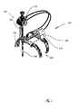
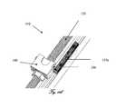
- FIG. 1is an isometric view of a four degree mechanism with an adapter
- FIG. 2is a schematic view representing four degree displacement
- FIGS. 3 a - 3 care schematic views showing optional working arrangements for shoulder ( 3 a ) and knee ( 3 b and 3 c ) surgery;
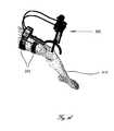
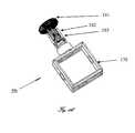
- FIG. 4is a schematic view showing optional displacement provided by a sliding adapter
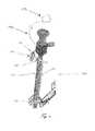
- FIG. 5is a schematic overview of a displacement mechanism
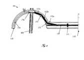
- FIG. 6is a schematic diagram of a sub-mechanism of arc reciprocal displacement:
- FIG. 7is a detailed view of a sub-mechanism of arc reciprocal displacement
- FIG. 8is a detailed view of a tilting sub-mechanism
- FIG. 9is a detailed view of a zoom sub-mechanism
- FIG. 10is a detailed view of a rotation sub-mechanism:
- FIG. 11 ais an isometric view of a locking sub-mechanism
- FIG. 11 bis an isometric view of a locking sub-mechanism in the locked position
- FIG. 11 cis an isometric view of a locking sub-mechanism in the unlocked position
- FIG. 12 ais a detailed view of a coupling/decoupling sub-mechanism
- FIG. 12 bis an enlarged view of a screw of the coupling/decoupling sub-mechanism
- FIG. 13 ais a schematic view representing an endoscope fixing sub-mechanism on the arc guides.
- FIG. 13 bis a schematic view representing an endoscope gripping unit alone.
- endoscopeand “laparoscope” refer interchangeably hereinafter to a fiber optical device that consists of a flexible tube. Glass or plastic filaments allow the internal refraction of light for viewing.
- This medical deviceis used in laparoscope, endoscope, laparoscopic and endoscopic surgeries. It is also in the scope of the invention wherein the term refers also to any means for looking within body cavities, especially inside the human body and mammalian body for medical reasons using an instrument; and especially to means for minimally invasive diagnostic medical procedure, such as rigid or flexible endoscopes, fiberscopes, means for robotic surgery, trocars, surgical working tools and diagnosing means etc.
- endoscopic surgeryand “laparoscopic surgery” interchangeably refer hereinafter to modern surgical technique in which operations into the body of a patient, e.g., in the abdomen, are performed through small incisions (usually 0.5 to 1.5 cm) as compared to larger incisions needed in traditional surgical procedures, or via natural cavities of the body.
- Laparoscopic surgeryincludes e.g., operations within the abdominal, pelvic or joint cavities.
- Endoscopy surgeryinvolves, inter alia, operations in the gastrointestinal tract, e.g., in the oesophagus, stomach and duodenum (esophagogastroduodenoscopy), small intestine, colon (colonoscopy, proctosigmoidoscopy), bile duct, endoscopic retrograde cholangiopancreatography (ERCP), duodenoscope-assisted cholangiopancreatoscopy, intraoperative cholangioscopy, the respiratory tract, the nose (rhinoscopy), the lower respiratory tract (bronchoscopy), the urinary tract (cystoscopy), the female reproductive system, the cervix (colposcopy), the uterus (hysteroscopy), the Fallopian tubes (falloscopy), normally closed body cavities (through a small incision), the abdominal or pelvic cavity (laparoscopy), the interior of a joint (arthroscopy) organs of the chest (thoracoscopy and mediastinoscopy), during pregnancy, the am
- the inventionconcerns an endoscope positioning system suited for all kinds of laparoscopic surgeries. It is best suited for orthopedic surgeries as defined below.
- Laparoscopic orthopedic surgeriesdiffer from abdominal laparoscopic surgeries in their dynamic nature: it is common in orthopedic surgeries to move the limbs of the patient from side to side; to bend the knee or the shoulder; or to stretch the patient's joints.
- Traditional endoscope holdersare fixed to the operation table and therefore do not allow the endoscope to follow the limb movement and thus are not used in these kinds of procedures.
- the present inventionprovides a quick and optimal endoscope setup, automatic and precise positioning of the endoscope, which allows the surgeon to use both his arms for simultaneously operating two tools at the same time, without interfering with the flow of the operation process.
- DOEDegrees of freedom
- the term “Degrees of freedom”refers hereinafter to a set of independent displacements that specify completely the displaced position of the endoscope or laparoscope as defined above.
- three DOE of linear displacement and three rotational DOBnamely, moving up and down, moving left and right, moving forward and backward, tilting up and down, turning left and right, tilting side to side.
- the present inventionrefers to a system essentially comprising means for at least four DOE selected from any of those defined above.
- distal portion and proximal portionrefer hereinafter to the side of the endoscope within the body of the patient, and outside the body of the patient, respectively.
- FIG. 1illustrating a typical endoscope positioning system 300 comprising a four freedom degree mechanism (FDFM) that moves the endoscope 500 and the body adapter 200 , thus enabling an optimal placement of the mechanism.
- the mechanism 100comprises a rotation sub-mechanism 310 , a tilting sub-mechanism 320 , an arc sub-mechanism 330 , and a zoom sub-mechanism 340 .
- the sub-mechanisms 310 , 320 , 330 , and 340are activated by a motor box 110 .
- FIG. 2showing the mechanism 300 enabling displacement of the endoscope 500 with FDFM.
- FDFM 300is used for linearly and angularly positioning the endoscope 500 relative to a joint incision.
- FIG. 3illustrating optional arrangements of the endoscope positioning system 300 on human limbs.
- the adaptor grippers 201 of body adapter 200embrace a human arm 400 ( FIG. 3 a ) and a human leg 410 ( FIGS. 3 h and 3 c ). By using the adapter stripes or grips ( 201 ) the adapter is fixed firmly to the patient's body allowing the mechanism to move the endoscope to the desired position.
- FIG. 4presenting the motor box 110 which is adapted to move relative to the adapter 200 .
- This optionallows the surgeon to attach the first gripper 201 firmly to the patient's limb, and then to position the mechanism 300 in the optimal arrangement relative to a joint incision (not shown) and finally to fix mechanism 300 by the second gripper 201 .
- FIG. 5disclosing a motor box 110 that contains the four motors.
- the transmission 115transmits motion from the motors located in the motor box 110 to a tilting sub-mechanism 320 and to the arc sub-mechanism 330 .
- Driving the zoom and rotation sub-mechanismsis performed by means of flexible shafts 199 .
- the endoscope 500passes through a transmission box 180 and a gimbal 170 .
- FIG. 6illustrating the arc sub-mechanism 330 .
- a nut 151is connected to a first link 152 a .
- Hinges 153are used for coupling links 152 b , 152 c , etc.
- Said hinges 153 and links 152 a , 152 b et ceteraare located in semicircular guide 154 .
- the number of the links 152 b , 152 c , etc., illustrateddoes not limit the described embodiment.
- the gimbal 170is coupled with hinge 153 to the distal end of the last link in the chain.
- the endoscope 500passes through the inner part of the gimbal 170 .
- FIG. 7illustrating the transmission.
- 115transmits rotational motion from a motor 157 a to the screw 155 .
- the nut 151moves along the screw 155 and acts upon the link 152 a .
- the nutis connected to a chain of links 152 by means of a fast release mechanism (not shown).
- the link chain 152is connected to the gimbal 170 that moves the endoscope 500 along the arc.
- the transmission 115transmits rotational motion from a motor 157 b to the arc 150 tilting the arc 150 at an angle of interest. Reciprocal movement of the gimbal 170 along the arc 150 and tilting the arc 150 are completely independent.
- a flexible shaft 199 acouples a motor 157 e located in the motor box 110 (not shown) to an axle 184 of a worm gear 181 .
- a drum 182mechanically connected to the worm gear 181 winds the wire 183 up, so that the distance between the drum 182 and the gimbal 170 becomes shorter.
- the spring 185maintains tension in wire 183 .
- the structure of the worm gearprevents the spring 185 from causing undesired displacement of the transmission box 180 .
- the motor 157 crotates in the opposite direction.
- the unwrapped wire 183lets the spring 183 extend. As a result the zoom box transmission rises.
- a flexible shaft 199 bcouples a motor 157 d located in motor box 110 (not shown) to an axle 202 of a worm gear 186 which rotates a cogwheel 187 .
- a part of the transmission, the cogwheel 187allows the endoscope to pass through a hole in its center.
- the friction between the cogwheel 187 and the endoscopeis high enough not to allow circular sliding between them.
- the aforesaid cog wheel 187has a centered passage for a proximal portion of the endoscope 500 .
- a locking sub-mechanism(not shown) is adapted to fix and release the endoscope 500 .
- Another optionis to use the housing 188 in order to transmit the rotation from the cogwheel by using the housing to apply the moment on the endoscope head.
- FIGS. 11 a , 11 b , and 11 cpresenting a quick locking sub-mechanism 350 for enabling or disenabling the arcing mechanism 330 .
- the sub-mechanism 350consists of a lever 190 furnished with two perpendicular slots 196 and 197 .
- the lever 190can rotate around an axis 191 ( FIG. 11 a ).
- FIG. 12 a and 12 bshowing a coupling/decoupling sub-mechanism 360 .
- the sub-mechanism 360connects and disconnects the arcing mechanism 330 of the endoscope positioning device.
- the mechanism 360connects/disconnects the arcing mechanism 330 to/from the motor to which it is connected to enable manual movement of the arcing mechanism 330 .
- the mechanism 360consists of a screw 198 that couples/decouples the screw 155 to the transmission 115 .
- FIGS. 13 a and 13 bdisclosing a quick fixing sub-mechanism 370 that enables connection and disconnection of the endoscope 500 and the gimbal 170 to/from arc 151 .
- This featureis of great significance for such operations when the surgeon needs/wants to switch modes or to clean the endoscope 500 .
- the gimbal 170is mechanically coupled to a cylinder 162 that serves as a hinge.
- the cylinder 162abuts against clamping means (e.g., balls) 163 which apply pressure on the gimbal 170 , thus prohibiting its release from cylinder 162 .
- clamping meanse.g., balls
- Disconnection of the gimbal 170 from the cylinder 162is attained by rotating the screw 161 counterclockwise.
- the pressure applied by the clamping means (balls 163 ) on the gimbalis eliminated, such that gimbal 170 and cylinder 162 can be pulled out from screw 161 .
- the endoscope positioning system 300is installed on the human limb.
- Precise positioning provided by the four freedom degree mechanism 100enables alignment of the position of the endoscope 500 before insertion into a human joint and displacement of a distal end of the endoscope 500 inside the human joint.
- Rigid fixing of the endoscope 500 relative to the human limbprovides freedom for the surgeon's hands from holding or maneuvering the endoscope 500 during a surgical operation.
Landscapes
- Health & Medical Sciences (AREA)
- Life Sciences & Earth Sciences (AREA)
- Surgery (AREA)
- Biomedical Technology (AREA)
- Medical Informatics (AREA)
- Optics & Photonics (AREA)
- Pathology (AREA)
- Radiology & Medical Imaging (AREA)
- Biophysics (AREA)
- Engineering & Computer Science (AREA)
- Physics & Mathematics (AREA)
- Heart & Thoracic Surgery (AREA)
- Nuclear Medicine, Radiotherapy & Molecular Imaging (AREA)
- Molecular Biology (AREA)
- Animal Behavior & Ethology (AREA)
- General Health & Medical Sciences (AREA)
- Public Health (AREA)
- Veterinary Medicine (AREA)
- Orthopedic Medicine & Surgery (AREA)
- Physical Education & Sports Medicine (AREA)
- Endoscopes (AREA)
Abstract
Description
- said EPS comprising:
- a. at least four freedom degree mechanisms (FDFM) (100); said FDOF are adapted to actuate the distal portion of said endoscope by maneuvering the proximal portion of said endoscope; said FDFM comprises at least a first, second, third and fourth means for providing said four degrees of freedom:
- i. said means of first degree of freedom is a rotation gab-
mechanism 310 adapted to rotate said endoscope around its longitudinal axis; - ii. said means of second degree of freedom is a tilting
sub-mechanism 320, comprising:- a. at least one transmission116 in mechanical communication with
arc 150; saidarc 150 is in mechanical communication with said endoscope; and, - b. at least one
motor 157bin reversible mechanical communication with said transmission116; said transmission116 is adapted to transmit rotational motion from saidmotor 157bto saidarc 150 such that saidarc 150 is titled at an angle of interest;
- a. at least one transmission116 in mechanical communication with
- iii. said means of third degree of freedom is an
arc sub-mechanism 330, comprising:- a, at least one
nut 151 adapted to linearly move along at least one screw (155); - b. a chain comprising a plurality of links, said chain is characterized by having a distal end and a proximal end; each of said links is in mechanical communication with at least one of its neighboring links; said chain is at least partially located in semicircular guides (154);
- said at least one
nut 151 is in mechanical communication with at least one first link (152a) in said proximal end of said chain; - a gimbal (170) through which said endoscope passes is in mechanical communication with at least one link located in said distal end of said chain;
- wherein said linear movement of said nut (151) is adapted to affects said first link (152a) in said chain such that the remaining links in said chain are forced to move along said
-
semicircular guides 154 so as to move saidgimbal 170 and saidendoscope 500 along saidarc 150;
- a, at least one
- iv. said means of fourth degree of freedom is a
zoom sub-mechanism 340;
- i. said means of first degree of freedom is a rotation gab-
- each of said first, second, third and fourth degree of freedom is characterized by an independent movement;
- b. at least one body adapter gripper (201) adapted to reversibly and firmly attach said EPS to said patient's body;
wherein said EPS is conformed to said movements of said organ by means of saidgripper 201 such that the orientation of said endoscope is adjustable accordingly to said movement.
- a. at least four freedom degree mechanisms (FDFM) (100); said FDOF are adapted to actuate the distal portion of said endoscope by maneuvering the proximal portion of said endoscope; said FDFM comprises at least a first, second, third and fourth means for providing said four degrees of freedom:
- said EPS comprising:
- a. at least one
worm gear 181; - b, at least one
drum 182 mechanically connected to saidworm gear 181; saiddrum 182 is characterized by a main longitudinal axis; saiddrum 182 is adapted to rotate awire 183 around said main axis, such that the distance between saiddrum 183 and agimbal 170 is shortened and a zoom motion is obtained.
- a. at least one
- a.
gimbal 170 through which said endoscopes passes; - b. at least one
screw 161; - c. a
cylinder 162 adapted to partially and reversibly accommodate saidscrew 161; - d. at least one clamping means163 reversibly housed within said
cylinder 162; said clamping means163 being in mechanical communication with saidscrew 161; said clamping means163 are adapted to reversibly apply pressure on said cylinder such that saidgimbal 170 is reversibly housed within saidcylinder 162.
- a.
- a. obtaining an endoscope positioning system (EPS,300); said EPS comprising:
- i. at least four freedom degree mechanisms (FDFM) (100) comprising at least a first, second, third and fourth means for providing said four degrees of freedom:
- a. said means of first degree of freedom is a
rotation sub-mechanism 310 adapted to rotate said endoscope around its longitudinal axis; - b. said means of second degree of freedom is a tilting
sub-mechanism 320, comprising:- i. at least one transmission116 in mechanical communication with
arc 150; saidarc 150 is in mechanical communication with said endoscope; and, - ii. at least one
motor 157bin reversible mechanical communication with said transmission116; - said transmission116 is adapted to transmit rotational motion from said
motor 157bto saidarc 150 such that saidarc 150 is titled at an angle of interest;
- i. at least one transmission116 in mechanical communication with
- c. said means of third degree of freedom is an
arc sub mechanism 330, comprising:- i. at least one
nut 151 adapted to linearly move along at least one screw (155); - ii. a chain comprising a plurality of links, said chain is characterized by having a distal end and a proximal end; each of said links is in mechanical communication with at least one of its neighboring links; said chain is at least partially located in semicircular guides (154);
- said at least one
nut 151 is in mechanical communication with at least one first link (152a) in said proximal end of said chain; - a gimbal (170) through which said endoscope passes is in mechanical communication with at least one link located in said distal end of said chain;
- wherein said linear movement of said nut (151) is adapted to affects said first link (1.52a) in said chain such that the remaining links in said chain are forced to move along said
semicircular guides 154 so as to move saidgimbal 170 and saidendoscope 500 along saidarc 150;
- i. at least one
- d. said means of fourth degree of freedom is a
zoom sub-mechanism 340; - each of said first, second, third and fourth degree of freedom is characterized by an independent movement;
- a. said means of first degree of freedom is a
- ii. at least one body adapter gripper (201);
- i. at least four freedom degree mechanisms (FDFM) (100) comprising at least a first, second, third and fourth means for providing said four degrees of freedom:
- b. reversibly and firmly attaching said EPS to said patient's body via said body adapter gripper (201);
- c. maneuvering the proximal portion of said endoscope in a movement selected from a group consisting of rotating, tilting, arcing or zooming thereby actuating and orienting the distal portion of said endoscope;
- wherein said step of reversibly and firmly attaching said EPS to said patient's body conforms said EPS is to said movements of said organ by means of said
gripper 201 such that the orientation of said endoscope is adjustable accordingly to said movement.
- a. obtaining an endoscope positioning system (EPS,300); said EPS comprising:
Claims (21)
Priority Applications (1)
| Application Number | Priority Date | Filing Date | Title |
|---|---|---|---|
| US12/441,838US8690755B2 (en) | 2006-09-21 | 2007-09-20 | Endoscopic positioning system |
Applications Claiming Priority (3)
| Application Number | Priority Date | Filing Date | Title |
|---|---|---|---|
| US84610906P | 2006-09-21 | 2006-09-21 | |
| US12/441,838US8690755B2 (en) | 2006-09-21 | 2007-09-20 | Endoscopic positioning system |
| PCT/IL2007/001161WO2008035345A2 (en) | 2006-09-21 | 2007-09-20 | Endoscopic positioning system |
Publications (2)
| Publication Number | Publication Date |
|---|---|
| US20090312600A1 US20090312600A1 (en) | 2009-12-17 |
| US8690755B2true US8690755B2 (en) | 2014-04-08 |
Family
ID=39200962
Family Applications (1)
| Application Number | Title | Priority Date | Filing Date |
|---|---|---|---|
| US12/441,838Active2030-06-12US8690755B2 (en) | 2006-09-21 | 2007-09-20 | Endoscopic positioning system |
Country Status (3)
| Country | Link |
|---|---|
| US (1) | US8690755B2 (en) |
| EP (1) | EP2073685B1 (en) |
| WO (1) | WO2008035345A2 (en) |
Cited By (24)
| Publication number | Priority date | Publication date | Assignee | Title |
|---|---|---|---|---|
| US20130253481A1 (en)* | 2008-02-05 | 2013-09-26 | Steerable Instruments B.V.B.A. | Steerable tube |
| US9757204B2 (en) | 2011-08-21 | 2017-09-12 | M.S.T. Medical Surgery Technologies Ltd | Device and method for assisting laparoscopic surgery rule based approach |
| US9757206B2 (en) | 2011-08-21 | 2017-09-12 | M.S.T. Medical Surgery Technologies Ltd | Device and method for assisting laparoscopic surgery—rule based approach |
| US9795282B2 (en) | 2011-09-20 | 2017-10-24 | M.S.T. Medical Surgery Technologies Ltd | Device and method for maneuvering endoscope |
| US20180049754A1 (en)* | 2015-03-13 | 2018-02-22 | Redemed S.R.L. | Intervertebral prosthesis, apparatus for implanting intervertebral prostheses and surgical method for implanting intervertebral prostheses, particularly for percutaneous mini-invasive surgery procedures |
| US9943372B2 (en) | 2005-04-18 | 2018-04-17 | M.S.T. Medical Surgery Technologies Ltd. | Device having a wearable interface for improving laparoscopic surgery and methods for use thereof |
| US10413374B2 (en) | 2018-02-07 | 2019-09-17 | Distalmotion Sa | Surgical robot systems comprising robotic telemanipulators and integrated laparoscopy |
| US10510447B2 (en) | 2011-07-27 | 2019-12-17 | Ecole Polytechnique Federale De Lausanne (Epfl) | Surgical teleoperated device for remote manipulation |
| US10548680B2 (en) | 2014-12-19 | 2020-02-04 | Distalmotion Sa | Articulated handle for mechanical telemanipulator |
| US10568709B2 (en) | 2015-04-09 | 2020-02-25 | Distalmotion Sa | Mechanical teleoperated device for remote manipulation |
| US10646294B2 (en) | 2014-12-19 | 2020-05-12 | Distalmotion Sa | Reusable surgical instrument for minimally invasive procedures |
| US10786272B2 (en) | 2015-08-28 | 2020-09-29 | Distalmotion Sa | Surgical instrument with increased actuation force |
| US10864049B2 (en) | 2014-12-19 | 2020-12-15 | Distalmotion Sa | Docking system for mechanical telemanipulator |
| US10864052B2 (en) | 2014-12-19 | 2020-12-15 | Distalmotion Sa | Surgical instrument with articulated end-effector |
| US10866783B2 (en) | 2011-08-21 | 2020-12-15 | Transenterix Europe S.A.R.L. | Vocally activated surgical control system |
| US11039820B2 (en) | 2014-12-19 | 2021-06-22 | Distalmotion Sa | Sterile interface for articulated surgical instruments |
| US11058503B2 (en) | 2017-05-11 | 2021-07-13 | Distalmotion Sa | Translational instrument interface for surgical robot and surgical robot systems comprising the same |
| US11076922B2 (en) | 2010-10-11 | 2021-08-03 | Ecole Polytechnique Federale De Lausanne (Epfl) | Mechanical manipulator for surgical instruments |
| US11844585B1 (en) | 2023-02-10 | 2023-12-19 | Distalmotion Sa | Surgical robotics systems and devices having a sterile restart, and methods thereof |
| US20240122464A1 (en)* | 2022-03-02 | 2024-04-18 | University-Town Hospital Of Chongqing Medical University | Single-operator laparoscope auxiliary operating device |
| US12114945B2 (en) | 2021-09-13 | 2024-10-15 | Distalmotion Sa | Instruments for surgical robotic system and interfaces for the same |
| US12329481B2 (en) | 2014-02-03 | 2025-06-17 | Distalmotion Sa | Mechanical teleoperated device comprising an interchangeable distal instrument |
| US12376927B2 (en) | 2018-02-07 | 2025-08-05 | Distalmotion Sa | Surgical robot systems comprising robotic telemanipulators and integrated laparoscopy |
| US12402960B2 (en) | 2010-10-11 | 2025-09-02 | Ecole Polytechnique Federale De Lausanne (Epfl) | Mechanical manipulator for surgical instruments |
Families Citing this family (9)
| Publication number | Priority date | Publication date | Assignee | Title |
|---|---|---|---|---|
| US8414475B2 (en) | 2005-04-18 | 2013-04-09 | M.S.T. Medical Surgery Technologies Ltd | Camera holder device and method thereof |
| US9295379B2 (en) | 2005-04-18 | 2016-03-29 | M.S.T. Medical Surgery Technologies Ltd. | Device and methods of improving laparoscopic surgery |
| WO2009002239A1 (en)* | 2007-06-28 | 2008-12-31 | St. Jude Medical Ab | Medical implantable lead and method for manufacturing the same |
| WO2009073577A2 (en)* | 2007-11-29 | 2009-06-11 | Surgiquest, Inc. | Surgical instruments with improved dexterity for use in minimally invasive surgical procedures |
| US11561762B2 (en)* | 2011-08-21 | 2023-01-24 | Asensus Surgical Europe S.A.R.L. | Vocally actuated surgical control system |
| US20130047391A1 (en)* | 2011-08-23 | 2013-02-28 | Takayuki Nakamura | Attachment jig for attaching self-propelled device to endoscope |
| WO2013042107A1 (en)* | 2011-09-20 | 2013-03-28 | M.S.T. Medical Surgery Technologies Ltd. | A device and method for maneuvering endoscope |
| EP2754405A1 (en)* | 2013-01-15 | 2014-07-16 | M.S.T. Medical Surgery Technologies Ltd. | A device for maneuvering endoscope |
| US11707190B1 (en) | 2022-05-27 | 2023-07-25 | Meditrina, Inc. | Medical robotic system |
Citations (11)
| Publication number | Priority date | Publication date | Assignee | Title |
|---|---|---|---|---|
| US4559928A (en)* | 1981-10-22 | 1985-12-24 | Olympus Optical Co., Ltd. | Endoscope apparatus with motor-driven bending mechanism |
| US5154723A (en)* | 1987-12-02 | 1992-10-13 | Olympus Optical Co., Ltd. | Cerebral surgery apparatus |
| US5201742A (en) | 1991-04-16 | 1993-04-13 | Hasson Harrith M | Support jig for a surgical instrument |
| US5571072A (en) | 1995-04-28 | 1996-11-05 | Kronner; Richard F. | Dual-axis endoscope holder |
| US5878193A (en) | 1992-08-10 | 1999-03-02 | Computer Motion, Inc. | Automated endoscope system for optimal positioning |
| US6024695A (en)* | 1991-06-13 | 2000-02-15 | International Business Machines Corporation | System and method for augmentation of surgery |
| US20030233102A1 (en)* | 2002-02-12 | 2003-12-18 | The University Of Tokyo | Active trocar |
| US6997866B2 (en) | 2002-04-15 | 2006-02-14 | Simon Fraser University | Devices for positioning implements about fixed points |
| US7048745B2 (en) | 1998-12-08 | 2006-05-23 | Intuitive Surgical | Surgical robotic tools, data architecture, and use |
| WO2006111966A2 (en) | 2005-04-18 | 2006-10-26 | M.S.T. Medical Surgery Technologies Ltd | Means and methods of improving laparoscopic surgery |
| US20110257475A1 (en)* | 2002-05-13 | 2011-10-20 | Perception Raisonnement Action En Me Decine | System for positioning on a patient an observation and/or intervention device |
Family Cites Families (1)
| Publication number | Priority date | Publication date | Assignee | Title |
|---|---|---|---|---|
| US5005559A (en)* | 1989-07-27 | 1991-04-09 | Massachusetts Institute Of Technology | Video-graphic arthroscopy system |
- 2007
- 2007-09-20USUS12/441,838patent/US8690755B2/enactiveActive
- 2007-09-20EPEP07827137.6Apatent/EP2073685B1/enactiveActive
- 2007-09-20WOPCT/IL2007/001161patent/WO2008035345A2/enactiveApplication Filing
Patent Citations (11)
| Publication number | Priority date | Publication date | Assignee | Title |
|---|---|---|---|---|
| US4559928A (en)* | 1981-10-22 | 1985-12-24 | Olympus Optical Co., Ltd. | Endoscope apparatus with motor-driven bending mechanism |
| US5154723A (en)* | 1987-12-02 | 1992-10-13 | Olympus Optical Co., Ltd. | Cerebral surgery apparatus |
| US5201742A (en) | 1991-04-16 | 1993-04-13 | Hasson Harrith M | Support jig for a surgical instrument |
| US6024695A (en)* | 1991-06-13 | 2000-02-15 | International Business Machines Corporation | System and method for augmentation of surgery |
| US5878193A (en) | 1992-08-10 | 1999-03-02 | Computer Motion, Inc. | Automated endoscope system for optimal positioning |
| US5571072A (en) | 1995-04-28 | 1996-11-05 | Kronner; Richard F. | Dual-axis endoscope holder |
| US7048745B2 (en) | 1998-12-08 | 2006-05-23 | Intuitive Surgical | Surgical robotic tools, data architecture, and use |
| US20030233102A1 (en)* | 2002-02-12 | 2003-12-18 | The University Of Tokyo | Active trocar |
| US6997866B2 (en) | 2002-04-15 | 2006-02-14 | Simon Fraser University | Devices for positioning implements about fixed points |
| US20110257475A1 (en)* | 2002-05-13 | 2011-10-20 | Perception Raisonnement Action En Me Decine | System for positioning on a patient an observation and/or intervention device |
| WO2006111966A2 (en) | 2005-04-18 | 2006-10-26 | M.S.T. Medical Surgery Technologies Ltd | Means and methods of improving laparoscopic surgery |
Non-Patent Citations (3)
| Title |
|---|
| International Preliminary Report on Patentability published Apr. 4, 2009 for PCT/IL2007/001161 filed Sep. 20, 2007. |
| International Search Report mailed Sep. 12, 2008 for PCT/IL2007/001161 filed Sep. 20, 2007. |
| Written Opinion mailed Sep. 12, 2008 for PCT/IL2007/001161 filed Sep. 20, 2007. |
Cited By (42)
| Publication number | Priority date | Publication date | Assignee | Title |
|---|---|---|---|---|
| US9943372B2 (en) | 2005-04-18 | 2018-04-17 | M.S.T. Medical Surgery Technologies Ltd. | Device having a wearable interface for improving laparoscopic surgery and methods for use thereof |
| US9579013B2 (en)* | 2008-02-05 | 2017-02-28 | Steerable Instruments nv | Steerable tube |
| US20130253481A1 (en)* | 2008-02-05 | 2013-09-26 | Steerable Instruments B.V.B.A. | Steerable tube |
| US10449010B2 (en) | 2008-02-05 | 2019-10-22 | Steerable Instruments nv | Steerable tube |
| US12402960B2 (en) | 2010-10-11 | 2025-09-02 | Ecole Polytechnique Federale De Lausanne (Epfl) | Mechanical manipulator for surgical instruments |
| US11076922B2 (en) | 2010-10-11 | 2021-08-03 | Ecole Polytechnique Federale De Lausanne (Epfl) | Mechanical manipulator for surgical instruments |
| US10510447B2 (en) | 2011-07-27 | 2019-12-17 | Ecole Polytechnique Federale De Lausanne (Epfl) | Surgical teleoperated device for remote manipulation |
| US11200980B2 (en) | 2011-07-27 | 2021-12-14 | Ecole Polytechnique Federale De Lausanne (Epfl) | Surgical teleoperated device for remote manipulation |
| US10866783B2 (en) | 2011-08-21 | 2020-12-15 | Transenterix Europe S.A.R.L. | Vocally activated surgical control system |
| US9757204B2 (en) | 2011-08-21 | 2017-09-12 | M.S.T. Medical Surgery Technologies Ltd | Device and method for assisting laparoscopic surgery rule based approach |
| US9937013B2 (en) | 2011-08-21 | 2018-04-10 | M.S.T. Medical Surgery Technologies Ltd | Device and method for assisting laparoscopic surgery—rule based approach |
| US9757206B2 (en) | 2011-08-21 | 2017-09-12 | M.S.T. Medical Surgery Technologies Ltd | Device and method for assisting laparoscopic surgery—rule based approach |
| US9795282B2 (en) | 2011-09-20 | 2017-10-24 | M.S.T. Medical Surgery Technologies Ltd | Device and method for maneuvering endoscope |
| US12329481B2 (en) | 2014-02-03 | 2025-06-17 | Distalmotion Sa | Mechanical teleoperated device comprising an interchangeable distal instrument |
| US11478315B2 (en) | 2014-12-19 | 2022-10-25 | Distalmotion Sa | Reusable surgical instrument for minimally invasive procedures |
| US11571195B2 (en) | 2014-12-19 | 2023-02-07 | Distalmotion Sa | Sterile interface for articulated surgical instruments |
| US10864052B2 (en) | 2014-12-19 | 2020-12-15 | Distalmotion Sa | Surgical instrument with articulated end-effector |
| US11039820B2 (en) | 2014-12-19 | 2021-06-22 | Distalmotion Sa | Sterile interface for articulated surgical instruments |
| US12262880B2 (en) | 2014-12-19 | 2025-04-01 | Distalmotion Sa | Sterile interface for articulated surgical instruments |
| US10646294B2 (en) | 2014-12-19 | 2020-05-12 | Distalmotion Sa | Reusable surgical instrument for minimally invasive procedures |
| US10864049B2 (en) | 2014-12-19 | 2020-12-15 | Distalmotion Sa | Docking system for mechanical telemanipulator |
| US12262969B2 (en) | 2014-12-19 | 2025-04-01 | Distalmotion Sa | Reusable surgical instrument for minimally invasive procedures |
| US10548680B2 (en) | 2014-12-19 | 2020-02-04 | Distalmotion Sa | Articulated handle for mechanical telemanipulator |
| US20180049754A1 (en)* | 2015-03-13 | 2018-02-22 | Redemed S.R.L. | Intervertebral prosthesis, apparatus for implanting intervertebral prostheses and surgical method for implanting intervertebral prostheses, particularly for percutaneous mini-invasive surgery procedures |
| US10568709B2 (en) | 2015-04-09 | 2020-02-25 | Distalmotion Sa | Mechanical teleoperated device for remote manipulation |
| US11337716B2 (en) | 2015-08-28 | 2022-05-24 | Distalmotion Sa | Surgical instrument with increased actuation force |
| US10786272B2 (en) | 2015-08-28 | 2020-09-29 | Distalmotion Sa | Surgical instrument with increased actuation force |
| US11944337B2 (en) | 2015-08-28 | 2024-04-02 | Distalmotion Sa | Surgical instrument with increased actuation force |
| US12295688B2 (en) | 2017-05-11 | 2025-05-13 | Distalmotion Sa | Translational instrument interface for surgical robot and surgical robot systems comprising the same |
| US12262968B2 (en) | 2017-05-11 | 2025-04-01 | Distalmotion Sa | Translational instrument interface for surgical robot and surgical robot systems comprising the same |
| US11058503B2 (en) | 2017-05-11 | 2021-07-13 | Distalmotion Sa | Translational instrument interface for surgical robot and surgical robot systems comprising the same |
| US12161438B2 (en) | 2018-02-07 | 2024-12-10 | Distalmotion Sa | Surgical robot systems comprising robotic telemanipulators and integrated laparoscopy |
| US12290328B2 (en) | 2018-02-07 | 2025-05-06 | Distalmotion Sa | Surgical robot systems comprising robotic telemanipulators and integrated laparoscopy |
| US11510745B2 (en) | 2018-02-07 | 2022-11-29 | Distalmotion Sa | Surgical robot systems comprising robotic telemanipulators and integrated laparoscopy |
| US12376927B2 (en) | 2018-02-07 | 2025-08-05 | Distalmotion Sa | Surgical robot systems comprising robotic telemanipulators and integrated laparoscopy |
| US10413374B2 (en) | 2018-02-07 | 2019-09-17 | Distalmotion Sa | Surgical robot systems comprising robotic telemanipulators and integrated laparoscopy |
| US12114945B2 (en) | 2021-09-13 | 2024-10-15 | Distalmotion Sa | Instruments for surgical robotic system and interfaces for the same |
| US20240122464A1 (en)* | 2022-03-02 | 2024-04-18 | University-Town Hospital Of Chongqing Medical University | Single-operator laparoscope auxiliary operating device |
| US12082899B2 (en) | 2023-02-10 | 2024-09-10 | Distalmotion Sa | Surgical robotics systems and devices having a sterile restart, and methods thereof |
| US12089908B2 (en) | 2023-02-10 | 2024-09-17 | Distalmotion Sa | Surgical robotics systems and devices having a sterile restart, and methods thereof |
| US11844585B1 (en) | 2023-02-10 | 2023-12-19 | Distalmotion Sa | Surgical robotics systems and devices having a sterile restart, and methods thereof |
| US12349998B2 (en) | 2023-02-10 | 2025-07-08 | Distalmotion Sa | Surgical robotics systems and devices having a sterile restart, and methods thereof |
Also Published As
| Publication number | Publication date |
|---|---|
| EP2073685A2 (en) | 2009-07-01 |
| EP2073685B1 (en) | 2024-02-14 |
| WO2008035345A3 (en) | 2009-05-07 |
| US20090312600A1 (en) | 2009-12-17 |
| EP2073685A4 (en) | 2014-04-30 |
| WO2008035345A2 (en) | 2008-03-27 |
Similar Documents
| Publication | Publication Date | Title |
|---|---|---|
| US8690755B2 (en) | Endoscopic positioning system | |
| US12089809B2 (en) | Minimally invasive surgical system | |
| US10695136B2 (en) | Preventing instrument/tissue collisions | |
| US20070270651A1 (en) | Device and method for illuminating an in vivo site | |
| US8333755B2 (en) | Coupler to transfer controller motion from a robotic manipulator to an attached instrument | |
| US8504134B2 (en) | Laterally fenestrated cannula | |
| US20110144659A1 (en) | N degrees-of-freedom (dof) laparoscope maneuverable system | |
| US20060241728A1 (en) | Control equipment for holding a laparoscopic probe |
Legal Events
| Date | Code | Title | Description |
|---|---|---|---|
| AS | Assignment | Owner name:M.S.T. MEDICAL SURGERY TECHNOLOGIES LTD., ISRAEL Free format text:ASSIGNMENT OF ASSIGNORS INTEREST;ASSIGNOR:SHOLEV, MORDEHAI;REEL/FRAME:022424/0900 Effective date:20090315 | |
| STCF | Information on status: patent grant | Free format text:PATENTED CASE | |
| FPAY | Fee payment | Year of fee payment:4 | |
| AS | Assignment | Owner name:TRANSENTERIX EUROPE, S.A.R.L., SWITZERLAND Free format text:ASSIGNMENT OF ASSIGNORS INTEREST;ASSIGNOR:M.S.T. MEDICAL SURGERY TECHNOLOGIES LTD.;REEL/FRAME:047947/0438 Effective date:20181031 | |
| AS | Assignment | Owner name:GREAT BELIEF INTERNATIONAL LIMITED, VIRGIN ISLANDS Free format text:ASSIGNMENT OF ASSIGNORS INTEREST;ASSIGNORS:TRANSENTERIX, INC.;TRANSENTERIX EUROPE, S.A.R.L.;REEL/FRAME:050944/0657 Effective date:20191030 Owner name:GREAT BELIEF INTERNATIONAL LIMITED, VIRGIN ISLANDS, BRITISH Free format text:ASSIGNMENT OF ASSIGNORS INTEREST;ASSIGNORS:TRANSENTERIX, INC.;TRANSENTERIX EUROPE, S.A.R.L.;REEL/FRAME:050944/0657 Effective date:20191030 | |
| MAFP | Maintenance fee payment | Free format text:PAYMENT OF MAINTENANCE FEE, 8TH YR, SMALL ENTITY (ORIGINAL EVENT CODE: M2552); ENTITY STATUS OF PATENT OWNER: SMALL ENTITY Year of fee payment:8 |